

Page 1

N
E
A
R
E
N
T
E
O
I
G
N
U
A
M
O
T
G
T
X
E
N
AUTOMGEN
www.irai.com
8
Page 2

Page 3

ENVIRONMENT................................................................................................................................................. 13
INSTALLATION ................................................................................................................................................. 15
Configuration required..............................................................................................................................15
Installation in a network ............................................................................................................................ 15
NEW FEATURES OF AUTOMGEN8................................................................................................................... 16
Choice of “Beginner / Expert” mode......................................................................................................... 16
Increased integration of the Grafcet 60848 standard................................................................................ 16
Compatibility of files.................................................................................................................................. 16
Physical engine integrated to IRIS3D........................................................................................................ 16
Enhanced 3D object handling in IRIS3 D................................................................................................... 16
Improved links between AUTOMGEN and IRIS3D objects....................................................................... 16
Textured IRIS3D objects............................................................................................................................ 16
Drag and drop from IRIS3D to AUTOMGEN sheets................................................................................. 17
AUTOMSIM user-definable object ............................................................................................................ 17
Drag and drop from AUTOMSIM to AUTOMGEN sheets ........................................................................ 17
Improvements to the environment.............................................................................................................. 17
ENVIRONMENT ................................................................................................................................................. 18
Start............................................................................................................................................................ 18
General views ............................................................................................................................................ 19
Selecting targets in expert mode ................................................................................................................ 21
Selecting targets in beginner mode............................................................................................................ 21
Palettes in expert mode.............................................................................................................................. 22
Palettes in beginner mode.......................................................................................................................... 22
Displaying or hiding the project window or message window .................................................................. 24
Displaying the work space in full screen mode.......................................................................................... 24
Keyboard shortcuts .................................................................................................................................... 24
LICENSES.......................................................................................................................................................... 25
Registering a license.................................................................................................................................. 25
Sending a user code to IRAI....................................................................................................................... 26
Sending a file by e-mail (the best solution)............................................................................................................ 26
Copying the user code in an e-mail message......................................................................................................... 27
By fax (not recommended) .................................................................................................................................... 27
By telephone (highly unadvisable)......................................................................................................................... 27
Entering the validation/enable code .......................................................................................................... 27
Validating by a e-mail received file....................................................................................................................... 27
Validating for a code received in the text of an e-mail .......................................................................................... 27
Validating for a code received by fax or telephone................................................................................................ 27
Modifying a license.................................................................................................................................... 27
Moving a license from one computer to another........................................................................................ 28
Network licenses ........................................................................................................................................ 29
Adding a network license....................................................................................................................................... 30
Modifying a license ............................................................................................................................................... 30
Connecting to client stations.................................................................................................................................. 30
Additional information on installing AUTOMGEN in a network environment .......................................... 31
General information............................................................................................................................................... 31
Installing AUTOMGEN8 on a file server............................................................................................................... 31
Installing one or more AUTOMGEN8 licenses on a network license manager...................................................... 31
Installing the network license server as a service...................................................................................................33
Uninstallation ............................................................................................................................................ 34
Errors......................................................................................................................................................... 34
THE PROJECT.................................................................................................................................................... 35
Files generated with AUTOMGEN7........................................................................................................... 35
Importing an application from an earlier version of AUTOMGEN (version 6 or earlier)........................ 35
Generating a free distribution executable file............................................................................................ 35
Modifying project properties..................................................................................................................... 36
Modifying security options.................................................................................................................................... 36
Advanced options .................................................................................................................................................. 36
User interface......................................................................................................................................................... 36
Model..................................................................................................................................................................... 36
Automatic GO........................................................................................................................................................ 37
THE BROWSER.................................................................................................................................................. 38
Page 4

Sheets......................................................................................................................................................... 39
Adding a new sheet................................................................................................................................................ 39
Importing old AUTOMGEN version sheets, importing CADEPA sheets............................................................. 40
Modifying the sheet compilation order.................................................................................................................. 40
Deleting a sheet from the list................................................................................................................................. 41
Exporting a sheet to a « .GR7 » file....................................................................................................................... 41
Copying, Cutting, Pasting a sheet.......................................................................................................................... 41
Renaming a sheet................................................................................................................................................... 41
Modifying sheet properties. ................................................................................................................................... 41
Symbols...................................................................................................................................................... 42
Creating a symbol table ......................................................................................................................................... 42
Importing a symbol table....................................................................................................................................... 42
Configuration............................................................................................................................................. 43
Post-processors ...................................................................................................................................................... 43
Compiler options.................................................................................................................................................... 43
Documentation........................................................................................................................................... 43
Generated files........................................................................................................................................... 44
Generating the instruction list in pivot code.......................................................................................................... 44
Generating the cross reference list......................................................................................................................... 44
Post-processors ...................................................................................................................................................... 44
Settings....................................................................................................................................................... 44
Viewing and modifying a variable or variable table.............................................................................................. 44
IRIS objects................................................................................................................................................ 46
Adding an IRIS 2D object...................................................................................................................................... 46
Deleting an IRIS 2D object.................................................................................................................................... 47
Displaying or hiding an IRIS 2D object................................................................................................................. 47
Cutting, copying, pasting an IRIS 2D object..........................................................................................................47
Adding a new IRIS 2D object on a console........................................................................................................... 47
Modifying the properties of an IRIS 2D object...................................................................................................... 47
Setting an object model accessible on the assistant................................................................................................ 48
Importing an IRIS 2D object in an earlier version of AUTOMGEN..................................................................... 49
Creating an IRIS 3D console ................................................................................................................................. 49
Resources................................................................................................................................................... 50
Adding a file to the resources ................................................................................................................................50
Deleting a file from the resources.......................................................................................................................... 50
Renaming a file in the resources............................................................................................................................ 50
Modifying a file in the resources........................................................................................................................... 50
Adding and converting 3D STUDIO files in the resources.................................................................................... 50
External modules ....................................................................................................................................... 50
DESIGNING PROGRAMS..................................................................................................................................... 52
Designing with the assistant ...................................................................................................................... 52
Designing with the shortcut menu.............................................................................................................. 53
Designing with the pallet ........................................................................................................................... 53
Enhancing and customizing the pallet.................................................................................................................... 53
Designing with the keyboard keys.............................................................................................................. 53
Delete block........................................................................................................................................................... 53
Link blocks............................................................................................................................................................ 53
Grafcet blocks ............................................................................................................................... ......................... 54
Flowchart blocks.................................................................................................................................................... 56
Ladder blocks......................................................................................................................................................... 56
Action blocks......................................................................................................................................................... 57
Test blocks............................................................................................................................................................. 58
Organization chart blocks...................................................................................................................................... 58
Function block blocks............................................................................................................................................ 58
Other blocks........................................................................................................................................................... 59
Documenting program elements................................................................................................................ 59
Adding symbols.......................................................................................................................................... 60
RUNNING AN APPLICATION ............................................................................................................................... 62
To run an application easily................................................................................................................................... 62
To end the run........................................................................................................................................................ 62
To compile only..................................................................................................................................................... 62
To stop the compilation ......................................................................................................................................... 62
To connect to a processor or install a PC............................................................................................................... 62
To disconnect a processor or uninstall a PC........................................................................................................... 62
To put the target in RUN mode.............................................................................................................................. 62
Page 5

To put the target in STOP mode ............................................................................................................................ 62
To initialize the target............................................................................................................................................ 62
To run a program cycle on the target (generally not supported on processors)...................................................... 63
To activate the dynamic display.............................................................................................................................63
THE COMPILER ................................................................................................................................................. 64
Modifying compiler options ....................................................................................................................... 64
Displaying compilation messages.............................................................................................................. 64
Finding an error........................................................................................................................................ 64
RUNNING PROGRAMS ON A PC ......................................................................................................................... 66
Configuring the number of variables......................................................................................................... 66
PC system variables................................................................................................................................... 67
Modifying the run period ........................................................................................................................... 68
Driving inputs/outputs ............................................................................................................................... 68
IRIS 2D REFERENCES....................................................................................................................................... 70
Modifying object display............................................................................................................................ 70
Modifying object characteristics................................................................................................................ 71
Removing an object............................................................................................................................................... 71
Dimensioning an object ......................................................................................................................................... 71
Moving an object................................................................................................................................................... 71
Putting an object in « User » mode...................................................................................................................... 71
Putting an object in « Configuration » mode ....................................................................................................... 71
Modifying the characteristics of an object ............................................................................................................. 71
Block access to configuration for all objects ............................................................................................. 72
Basic objects, preset objects ...................................................................................................................... 72
List of basic objects.................................................................................................................................... 72
« Console » object.................................................................................................................................................. 72
The « Button and light » object............................................................................................................................. 72
The« Object » object.............................................................................................................................................. 72
The « Digital value » object................................................................................................................................... 72
The « Screen, keyboard, message list » object....................................................................................................... 72
The « Sound » object............................................................................................................................................. 73
The « Data archive » object................................................................................................................................... 73
The « Program » object.......................................................................................................................................... 73
The « Dialogue box » object.................................................................................................................................. 73
The « Analog value » object.................................................................................................................................. 73
Practical experience.................................................................................................................................. 73
Step 1..................................................................................................................................................................... 73
Step 2..................................................................................................................................................................... 74
Step 3..................................................................................................................................................................... 74
Step 4..................................................................................................................................................................... 74
Step 5..................................................................................................................................................................... 74
Step 6..................................................................................................................................................................... 75
Step 7..................................................................................................................................................................... 76
Creating an autonomous supervision application ..................................................................................... 77
Syntax for accessing the state of variables................................................................................................. 77
Boolean state.......................................................................................................................................................... 77
Numeric state......................................................................................................................................................... 78
Modifying the state................................................................................................................................................ 78
Special orders......................................................................................................................................................... 78
Interchanging objects............................................................................................................................................. 79
Details of a « Console » object.................................................................................................................. 79
« Aspect » tab ........................................................................................................................................................ 79
« Bitmap » tab........................................................................................................................................................ 80
« Links » tab .......................................................................................................................................................... 80
« Options » tab....................................................................................................................................................... 81
« Sisters » tab......................................................................................................................................................... 81
« External » ta b...................................................................................................................................................... 81
Details of an « Illuminated Button » object ............................................................................................... 82
« Aspect » tab ........................................................................................................................................................ 82
« Links » tab .......................................................................................................................................................... 82
« Options » tab....................................................................................................................................................... 83
Details of a « Digital value » object .......................................................................................................... 85
« Aspect » tab ........................................................................................................................................................ 85
« Texts » tab........................................................................................................................................................... 86
« Links » tab .......................................................................................................................................................... 86
Page 6

Details of an « Analog value » object........................................................................................................ 86
« Aspect » tab ........................................................................................................................................................ 86
« Links » tab .......................................................................................................................................................... 87
« Limits» tab.......................................................................................................................................................... 87
« Graduations » tab................................................................................................................................................ 88
Details of « Screen, keyboard, message list » object ................................................................................. 89
Links with the application...................................................................................................................................... 89
Message classes ..................................................................................................................................................... 90
« Aspect » tab ........................................................................................................................................................ 90
This is used to set an object type. See chapter links with the application.............................................................. 90
« Links » tab .......................................................................................................................................................... 91
« List » tab ............................................................................................................................................................. 91
« Options » tab....................................................................................................................................................... 92
« Messages » tab.................................................................................................................................................... 93
Details of « Data archive » object ............................................................................................................. 93
« Aspect » tab ........................................................................................................................................................ 93
« Data » tab............................................................................................................................................................ 93
« Options » tab....................................................................................................................................................... 95
« Tables » tab......................................................................................................................................................... 95
« Graph» tab .......................................................................................................................................................... 96
« Graduations » tab................................................................................................................................................ 97
« Grid » tab............................................................................................................................................................ 98
Details of « Object » object...................................................................................................................... 100
« Aspect » tab ...................................................................................................................................................... 100
« Links » tab ........................................................................................................................................................ 101
« Formats » tab .................................................................................................................................................... 102
« Bitmap » tab...................................................................................................................................................... 102
« Wmf » tab ......................................................................................................................................................... 103
« Colors » tab....................................................................................................................................................... 103
« Gauge » tab............................................................................................................................... ........................ 104
« Sensor» tab........................................................................................................................................................ 104
« Options » tab..................................................................................................................................................... 105
Advanced techniques............................................................................................................................... ............ 105
Details of « Sound » object ...................................................................................................................... 106
« Aspect » tab ...................................................................................................................................................... 106
« Sounds » tab...................................................................................................................................................... 106
Details of « Dialogue box » object........................................................................................................... 106
« Aspect » tab ...................................................................................................................................................... 106
« Links » tab............................................................................................................................................. 107
« Messages » tab.................................................................................................................................................. 108
Details of « Program » object.................................................................................................................. 108
Run time distribution........................................................................................................................................... 108
Display................................................................................................................................................................. 108
Syntax .................................................................................................................................................................. 109
Stating variables................................................................................................................................................... 109
Writing a program................................................................................................................................................ 109
Constants ............................................................................................................................................................. 110
Assignment.......................................................................................................................................................... 110
Calculations ......................................................................................................................................................... 110
Tests..................................................................................................................................................................... 111
Loops................................................................................................................................................................... 111
Variable or variable table address........................................................................................................................ 112
List of functions................................................................................................................................................... 112
Error messages..................................................................................................................................................... 118
« Aspect » tab ...................................................................................................................................................... 119
« Program » tab.................................................................................................................................................... 120
IRIS 2D EXAMPLES ........................................................................................................................................ 121
Example of composed objects.................................................................................................................. 121
Example of using the « Screen, keyboard, message list » object as a message list.................................. 124
Example of using the « SCREEN KEY » object as a terminal................................................................. 125
Example of an application composed of multiple pages.......................................................................... 126
Example of using the «OBJECT » object................................................................................................. 126
Example of using the «ARCHIVE» object................................................................................................ 131
Example of using the «PROG » object..................................................................................................... 131
Examples of supervision application 1................................................................................................... 131
Page 7

Examples of supervision application 2.................................................................................................... 132
Example of operating part simulation 1.................................................................................................. 133
Example of operating part simulation 2................................................................................................... 134
IRIS 3D REFERENCES..................................................................................................................................... 135
Tutorial.................................................................................................................................................... 136
Creating an IRIS 3D console ................................................................................................................... 136
Adding 3D files to the project.................................................................................................................. 137
Configuring the objects............................................................................................................................ 138
Adding objects to the 3D world................................................................................................................ 139
Removing a 3D file from the resources.................................................................................................... 139
Removing an object from a 3D world ...................................................................................................... 139
Importing an “enhanced” object ............................................................................................................. 139
Exporting an “Enhanced” object ............................................................................................................ 142
Example of creating a 3D simulation based on enhanced objects........................................................... 143
Applying a behavior to an object............................................................................................................. 154
Name of AUTOMGEN variables ........................................................................................................................ 155
Adding a translation............................................................................................................................................. 156
Adding a rotation................................................................................................................................................. 159
Adding a color change......................................................................................................................................... 160
Adding a link ....................................................................................................................................................... 161
Adding another behavior...................................................................................................................................... 162
Physical engine........................................................................................................................................ 163
IRIS 3D example ...................................................................................................................................... 165
LANGUAGE....................................................................................................................................................... 167
COMMON ELEMENTS ...................................................................................................................................... 169
Variables.................................................................................................................................................. 169
Booleen variables................................................................................................................................................. 169
Numeric variables................................................................................................................................................ 170
Time delay........................................................................................................................................................... 170
Actions ..................................................................................................................................................... 172
Assignment of a boolean variable........................................................................................................................ 172
Complement assignment of a boolean variable.................................................................................................... 173
Setting a boolean variable to one......................................................................................................................... 174
Resetting a boolean variable................................................................................................................................ 175
Inverting a boolean variable................................................................................................................................. 175
Resetting a counter, a word or a long................................................................................................................... 176
Incrementing a counter, a word or a long............................................................................................................. 177
Decrementing a counter, word or long................................................................................................................. 177
Time delays.......................................................................................................................................................... 178
Interferences among the actions........................................................................................................................... 178
IEC1131-3 standard actions................................................................................................................................. 179
Multiple actions................................................................................................................................................... 180
Literal code.......................................................................................................................................................... 180
Tests......................................................................................................................................................... 180
General form........................................................................................................................................................ 181
Test modifier........................................................................................................................................................ 181
Time delays.......................................................................................................................................................... 182
Priority of boolean operators................................................................................................................................ 182
Always true test ................................................................................................................................................... 182
Numeric variable test........................................................................................................................................... 182
Transitions on multiple lines................................................................................................................................ 184
Use of symbols......................................................................................................................................... 184
Symbol syntax ..................................................................................................................................................... 184
Automatic symbols.............................................................................................................................................. 184
Automatic symbol syntax .................................................................................................................................... 184
How does the compiler manage the automatic symbols ?.................................................................................... 185
Range of variable attribution................................................................................................................................ 185
Fixed-address symbols......................................................................................................................................... 185
Examples.................................................................................................................................................. 186
Grafcet..................................................................................................................................................... 188
Simple Grafcet..................................................................................................................................................... 188
Divergence and convergence in « And » ............................................................................................................ 191
Divergence and convergence in « Or »................................................................................................................ 193
Page 8

Destination and source steps, destination and source transitions......................................................................... 195
Multiple actions, conditioned actions .................................................................................................................. 196
Conditional actions, event-based actions............................................................................................................. 197
Actions on activation or deactivation of a step.................................................................................................... 197
Actions on transition crossing.............................................................................................................................. 197
Synchronization................................................................................................................................................... 198
Grafcet setting...................................................................................................................................................... 199
Grafcet forcings (60848 standard) ....................................................................................................................... 206
Macro-steps.......................................................................................................................................................... 207
Encapsulating steps.............................................................................................................................................. 210
Grafcet / Ladder and Grafcet / Flow chars links.................................................................................................. 212
Counters............................................................................................................................................................... 213
Gemma..................................................................................................................................................... 214
Creating a Gemma............................................................................................................................................... 216
ontent of Gemma rectangles ................................................................................................................................ 216
Obtaining a corresponding Grafcet...................................................................................................................... 216
Printing Gemma................................................................................................................................................... 217
Exporting Gemma................................................................................................................................................ 217
Example of Gemma............................................................................................................................................. 217
Ladder...................................................................................................................................................... 220
Example of Ladder............................................................................................................................................... 221
Flow chart................................................................................................................................................ 222
Drawing flow charts............................................................................................................................................. 223
Example of a flow chart....................................................................................................................................... 224
Literal languages..................................................................................................................................... 226
How is a literal language used?............................................................................................................................ 226
Setting a code box................................................................................................................................................ 227
Low level literal language.................................................................................................................................... 228
Macro-instruction................................................................................................................................................. 285
Libraries............................................................................................................................................................... 286
Pre-defined macro-instructions............................................................................................................................ 286
Description of pre-defined macro-instructions..................................................................................................... 286
Example of low level literal language.................................................................................................................. 288
Extended literal language........................................................................................................................ 291
Writing boolean equations................................................................................................................................... 292
Writing numeric equations................................................................................................................................... 293
IF...THEN...ELSE...structure......................................................................................................................................... 294
WHILE ... ENDWHILE structure........................................................................................................................ 295
Example of a program in extended literal language............................................................................................. 295
ST literal language................................................................................................................................... 296
General Information............................................................................................................................................. 296
Boolean equations................................................................................................................................................ 297
Numeric equations............................................................................................................................................... 298
Programming structures....................................................................................................................................... 299
Example of a program in extended literal language............................................................................................. 300
Organization chart................................................................................................................................... 300
Creating an organizational chart.......................................................................................................................... 301
Rectangle content................................................................................................................................................. 302
Illustration ............................................................................................................................................... 302
Function blocks........................................................................................................................................ 304
Creating a function block..................................................................................................................................... 305
Drawing a block and creating a « .ZON » file ..................................................................................................... 305
Creating an « .LIB » file...................................................................................................................................... 307
Simple example of a function block..................................................................................................................... 307
Illustration............................................................................................................................................................ 308
Supplementary syntax.......................................................................................................................................... 311
Evolved function blocks........................................................................................................................... 312
Syntax .................................................................................................................................................................. 312
Differentiating between new and old function blocks.......................................................................................... 312
Example............................................................................................................................................................... 313
Predefined function blocks....................................................................................................................... 313
Conversion blocks................................................................................................................................................ 314
Time delay blocks................................................................................................................................................ 314
String blocks........................................................................................................................................................ 314
Word table blocks................................................................................................................................................ 314
Advanced techniques................................................................................................................................314
Page 9

Compiler generated code ..................................................................................................................................... 314
Optimizing generated code.................................................................................................................................. 315
EXAMPLES...................................................................................................................................................... 317
Regarding examples................................................................................................................................. 317
Simple grafcet...................................................................................................................................................... 317
Grafcet with an OR divergence............................................................................................................................ 318
Grafcet with an AND divergence........................................................................................................................ 319
Grafcet and synchronization................................................................................................................................ 320
Step setting .......................................................................................................................................................... 321
Destination and source steps................................................................................................................................ 322
Destination and source steps................................................................................................................................ 323
Setting Grafcets ................................................................................................................................................... 324
Memorizing Grafcets........................................................................................................................................... 325
Grafcet and macro-steps ...................................................................................................................................... 326
Linked sheets....................................................................................................................................................... 327
Flow chart............................................................................................................................................................ 329
Grafcet and Flow Chart........................................................................................................................................ 330
Literal language box ............................................................................................................................................ 331
Organizational chart............................................................................................................................................. 332
Organizational chart............................................................................................................................................. 333
Function block..................................................................................................................................................... 334
Function block..................................................................................................................................................... 335
Ladder............................................................................................................................... ................................... 336
Example developed on a train model................................................................................................................... 337
Educational training manual for AUTOMGEN users.............................................................................. 343
Distribution.............................................................................................................................................. 345
Doctor R. in the home automation kingdom ............................................................................................ 345
First example: « which came first the bulb or the switch … »................................................................. 346
Solution 1: natural language of an electrician: ladder.......................................................................................... 347
Solution 2: the sequential language of the automation specialist: Grafcet........................................................... 347
It's your turn to play …............................................................................................................................ 349
Second example: « time frames, time-switches and other time fun… »................................................... 349
Solution 1: simplicity........................................................................................................................................... 350
Solution 2: improvement...................................................................................................................................... 351
Third Example: « variation on the the me of coming and going… »........................................................ 352
Fourth example: « And the push button became intelligent … » ............................................................. 356
The solutions … ....................................................................................................................................... 359
« which came first the switch or the bulb … »..................................................................................................... 359
« time delays, time switches and other time fun… » ........................................................................................... 359
« variation on the theme of coming and going …».............................................................................................. 361
AUTOMSIM....................................................................................................................................................... 363
INTRODUCTION............................................................................................................................................... 365
INSTALLATION ............................................................................................................................................... 366
Practical experience................................................................................................................................366
AUTOMGEN’S “BEGINNER” MODE............................................................................................................... 370
USING AUTOMSIM...................................................................................................................................... 371
Organizing applications........................................................................................................................... 371
Opening an existing application.............................................................................................................. 371
Creating an AUTOMSIM sheet................................................................................................................ 371
Adding an object onto an AUTOMSIM sheet........................................................................................... 372
Using the palette...................................................................................................................................... 374
Selecting one or more objects.................................................................................................................. 375
Selecting one or more objects.................................................................................................................. 376
Deleting one or more objects................................................................................................................... 376
Changing the orientation of one or more objects .................................................................................... 376
Copying/cutting one or more objects to the clipboard............................................................................. 376
Pasting one or more objects from the clipboard...................................................................................... 377
Modifying object properties..................................................................................................................... 377
Exporting one or more objects................................................................................................................. 377
ADVANCED FUNCTIONS.................................................................................................................................. 378
Interactions between objects.................................................................................................................... 378
Creating sensors associated with a cylinder............................................................................................ 378
Page 10

Interactions between AUTOMSIM objects and the automaton program................................................. 380
Interactions between AUTOMSIM objects and the IRIS 3D operational unit simulator ......................... 381
Interactions between AUTOMSIM objects and the IRIS2D supervision objects ..................................... 382
How can a link be made between an IRIS2D pushbutton or switch and an AUTOMSIM pushbutton or switch?382
How can a link be made between an AUTOMSIM object and an IRIS2D indicator light?................................. 383
Drag and drop from an AUTOMSIM variable to an AUTOMGEN sheet................................................ 384
User-definable objects............................................................................................................................. 385
Designs .................................................................................................................................................... 387
List of design primitives........................................................................................................................... 388
Drawing primitive................................................................................................................................................ 388
Attribute primitives.............................................................................................................................................. 390
Other primitives................................................................................................................................................... 391
Program................................................................................................................................................... 392
List of programming primitives........................................................................................................................... 393
Connections ............................................................................................................................................. 395
Example ................................................................................................................................................... 396
POST-PROCESSORS........................................................................................................................................ 397
GENERAL INFORMATION ................................................................................................................................399
CONFIGURATION ............................................................................................................................................ 400
Configuration files ................................................................................................................................... 400
System ................................................................................................................................................................. 400
Variable functions................................................................................................................................................ 400
Start-up manufacturer code.................................................................................................................................. 400
End manufacturer code........................................................................................................................................ 400
Configuration by default.......................................................................................................................... 400
Modifying the default statements......................................................................................................................... 401
Using the default statements................................................................................................................................ 401
Displaying and modifying configuration elements................................................................................... 401
System...................................................................................................................................................... 401
Hardware configuration............................................................................................................................... ........ 401
Software configuration......................................................................................................................................... 402
Code generation options ...................................................................................................................................... 402
Stating the variables............................................................................................................................................. 402
Other elements..................................................................................................................................................... 402
See the « System » element in text format........................................................................................................... 402
Displaying system elements................................................................................................................................. 403
Variable functions.................................................................................................................................... 403
Single assignment................................................................................................................................................ 404
Linear assignment................................................................................................................................................ 404
Automatic assignment.......................................................................................................................................... 404
Types of AUTOMGEN elimination variables ..................................................................................................... 405
Modifying a variable function element................................................................................................................ 410
Adding a variable function element..................................................................................................................... 410
Deleting a variable function elemen t ................................................................................................................... 412
Associating an AUTOMGEN bit to a target system bit....................................................................................... 412
Associating a table of AUTOMGEN words to a table of fixed target words....................................................... 413
Associating AUTOMGEN words to target analog inputs or outputs................................................................... 414
Associating a table of AUTOMGEN bits to a table of target bits........................................................................ 414
See the variable functions in text format.............................................................................................................. 415
Start-up manufacturer code, end manufacturer code .............................................................................. 415
Reference to an AUTOMGEN variable............................................................................................................... 415
Referring to an AUTOMGEN application symbol.............................................................................................. 416
Setting and referring to a label............................................................................................................................. 416
Entering machine code in an application ................................................................................................ 416
Selecting connection options.................................................................................................................... 416
Selecting a connection mode.................................................................................................................... 417
Setting communication module parameters............................................................................................. 417
POST-PROCESSOR PL7.................................................................................................................................... 418
Communication module ........................................................................................................................... 418
Generating an executable file.................................................................................................................. 419
Direct generation of a binary file......................................................................................................................... 419
Generating an « .FEF » executable file................................................................................................................ 421
Using interrupt tasks................................................................................................................................423
Page 11

Specific examples..................................................................................................................................... 423
Analog inputs/outputs.......................................................................................................................................... 424
Fast counter TSX 37-10....................................................................................................................................... 424
Fast counter TSX 37-10 used in counting ............................................................................................................ 424
Fast counter TSX 37-22....................................................................................................................................... 424
ASI....................................................................................................................................................................... 424
MAGELIS ........................................................................................................................................................... 424
POST-PROCESSOR PL72.................................................................................................................................. 425
Selecting processor type .......................................................................................................................... 425
Specific syntax elements........................................................................................................................... 425
Calling up PL72 function blocks ......................................................................................................................... 425
Using a fast task................................................................................................................................................... 427
Communication module ........................................................................................................................... 428
Specific examples..................................................................................................................................... 428
Analog inputs/outputs.......................................................................................................................................... 429
Fast counter.......................................................................................................................................................... 430
Text blocks and xbt.............................................................................................................................................. 430
UNITELWAY text blocks................................................................................................................................... 433
TOR extension module........................................................................................................................................ 435
Conversion............................................................................................................................... ............................ 435
Time/date............................................................................................................................................................. 435
POST-PROCESSOR S7200................................................................................................................................436
Selecting CPU type .................................................................................................................................. 436
Communication module ........................................................................................................................... 436
Specific example....................................................................................................................................... 436
POST-PROCESSOR ABB.................................................................................................................................. 437
Selecting processor type .......................................................................................................................... 437
Processor AC31 ................................................................................................................................................... 437
Processor CS31.................................................................................................................................................... 437
Communication module ........................................................................................................................... 437
Utility....................................................................................................................................................... 437
Specific examples..................................................................................................................................... 437
Analog inputs/outputs.......................................................................................................................................... 438
Interrupt............................................................................................................................................................... 438
POST-PROCESSOR GE-FANUC / ALSPA....................................................................................................... 439
Selecting processor type .......................................................................................................................... 439
Communication module ........................................................................................................................... 439
Utility....................................................................................................................................................... 439
POST-PROCESSOR STEP5............................................................................................................................... 440
Communication module ........................................................................................................................... 440
Application structure ............................................................................................................................... 440
Selecting program blocks to use .......................................................................................................................... 443
Selecting data blocks ........................................................................................................................................... 443
Selecting processor type .......................................................................................................................... 444
Associating code written on a sheet to a program block ......................................................................... 444
Specific syntaxes ...................................................................................................................................... 444
Setting blocks....................................................................................................................................................... 445
POST-PROCESSOR TSX 07.............................................................................................................................. 447
Communication module ........................................................................................................................... 447
POST-PROCESSOR PS3-PS4............................................................................................................................ 449
Communication module ........................................................................................................................... 449
POST-PROCESSOR PS4.................................................................................................................................... 450
Module de communication....................................................................................................................... 450
Transferring programs to MOELLER SUCOSOFT software .................................................................. 450
Proceed as follows to import the file generated by AUTOMGEN in the MOELLER software then inject it in the
processor.
POST-PROCESSOR RPX................................................................................................................................... 455
Selecting processor type .......................................................................................................................... 455
Communication module ........................................................................................................................... 455
Utility....................................................................................................................................................... 455
POST-PROCESSOR PL71.................................................................................................................................. 456
Selecting processor type .......................................................................................................................... 456
Communication module ........................................................................................................................... 456
............................................................................................................................................................. 451
Page 12

Fast counter task...................................................................................................................................... 456
Specific examples..................................................................................................................................... 456
Counting .............................................................................................................................................................. 457
Fast counter.......................................................................................................................................................... 457
POST-PROCESSOR PB...................................................................................................................................... 458
Selecting processor type .......................................................................................................................... 458
Communication module ........................................................................................................................... 458
Specific syntaxes ...................................................................................................................................... 458
POST-PROCESSOR SMC.................................................................................................................................. 460
Selecting processor type .......................................................................................................................... 460
Communication module ........................................................................................................................... 460
Specific syntaxes ...................................................................................................................................... 460
POST-PROCESSOR S7300................................................................................................................................461
Communication module ........................................................................................................................... 461
Specific syntaxes ...................................................................................................................................... 461
Setting block variables......................................................................................................................................... 462
Calling up blocks................................................................................................................................................. 462
Importing in SIEMENS SIMATIC software ............................................................................................. 463
Structure of generated code..................................................................................................................... 465
Selecting program blocks to use .......................................................................................................................... 469
Associating code written on a sheet to a program block ......................................................................... 469
Specific examples..................................................................................................................................... 469
Calling up a STEP7 block.................................................................................................................................... 470
Using an OB block............................................................................................................................................... 470
POST-PROCESSOR OMRON............................................................................................................................ 471
Select PLC model..................................................................................................................................... 471
Communication module ........................................................................................................................... 471
Transferring applications to the CX-PROGRAMMER software.............................................................. 471
Specific syntax.......................................................................................................................................... 474
Associating code written on a sheet to a program block ......................................................................... 474
Specific example....................................................................................................................................... 474
POST-PROCESSOR ALSPA.............................................................................................................................. 475
Communication module ........................................................................................................................... 475
POST-PROCESSOR ZELIO............................................................................................................................... 476
Communication module ........................................................................................................................... 476
POST-PROCESSOR FESTO.............................................................................................................................. 477
Communication module ........................................................................................................................... 477
Generating a binary file........................................................................................................................... 477
Importation in a FESTO software workgroup......................................................................................... 477
POST-PROCESSOR ALLEN-BRADLEY......................................................................................................... 479
Communication module ........................................................................................................................... 479
Transferring programs to ROCKWELL RS-Logix 500 Software............................................................. 479
POST-PROCESSOR TWIDO............................................................................................................................. 481
Processor configuration selection............................................................................................................481
Communication module ........................................................................................................................... 481
POST-PROCESSOR MITSUBISHI.................................................................................................................... 482
Selecting the type of processor................................................................................................................. 482
Communication module ........................................................................................................................... 482
Transferring programs to MITSUBISHI FX-WIN software.................................................................... 483
Transferring programs to MITSUBISHI GX-DEVELOPPER software.................................................. 483
POST-PROCESSOR MITSUBISHI-Q ............................................................................................................... 485
Communication module ........................................................................................................................... 485
Transferring programs to MITSUBISHI GX-DEVELOPPER software.................................................. 485
POST-PROCESSOR GEM.................................................................................................................................. 486
Communication module ........................................................................................................................... 486
POST-PROCESSOR ZELIO 2............................................................................................................................ 487
Initializing the automaton........................................................................................................................ 487
Configuring the module ........................................................................................................................... 487
Communication module ........................................................................................................................... 487
POST-PROCESSOR PANASONIC.................................................................................................................... 488
Selecting the configuration of the automaton.......................................................................................... 488
Page 13

Communication module ........................................................................................................................... 488
Page 14

Page 15

Environment
Page 16

Page 17

Environment
Installation
If you are installing AUTOMGEN from the AUTOMGEN CD-ROM, place
it in your CD-ROM drive.
The installation is launched automatically.
If this does not occur, launch the “Setup.exe” executable which is in the
CD-ROM root.
Configuration required
PC compatible computer, with:
- WINDOWS 98 SE or WINDOWS ME or WINDOWS 2000 or
WINDOWS XP or WINDOWS 2003 or WINDOWS VISTA operating
system,
- 256 MB memory (depending on the operating system: the operating
system itself may require more memory),
- graphics board with a resolution of at least 1024 x 768 in 65536 colors.
Installation in a network
AUTOMGEN can be installed in a network environment.
Execute the installation procedure on the “server” PC (make sure you
have all of the access rights when you carry out the procedure).
To launch AUTOMGEN, on the client PCs, create a shortcut to the
“autom8.exe” executable of the AUTOMGEN installation directory on the
server PC.
Refer to the chapter “additional information on installing AUTOMGEN in
a network environment” for more information about installing
AUTOMGEN and licenses in a network environment.
AUTOMGEN8 15 ©opyright 1988-2007 IRAI
Page 18

Environment
8
New features of AUTOMGEN
Choice of “Beginner / Expert” mode
“Beginner” mode allows beginners to use a “simplified” environment that
is extremely easy to use.
Increased integration of the Grafcet 60848 standard
The new elements of this standard can now be accessed in the
contextual program editing menus.
Compatibility of files
The files generated by all of the AUTOMGEN8 versions can be re-read
by all of the AUTOMGEN
8
versions.
Physical engine integrated to IRIS3D
The TOKAMAK motor is integrated to IRIS3D. This enables an extremely
realistic simulation of the 3D operational units to be obtained.
Enhanced 3D object handling in IRIS3D
The saving and re-reading of objects and behaviors allows you to
manage libraries of easily reusable objects. Predefined objects
(cylinders, conveyor belts, etc) are proposed as standard. A 3D
operational unit simulation application can now be created in just a
couple of mouse clicks.
Improved links between AUTOMGEN and IRIS3D objects
Enhanced modes allow you to easily handle displacements of complex
objects between AUTOMGEN and IRIS3D. An AUTOMGEN variable
can, for example, give the speed of an object directly. Position reporting
can also be simulated in the manner of an absolute encoder.
Textured IRIS3D objects
Textured objects now provide IRIS3D with extraordinarily realistic
rendering.
AUTOMGEN8 16 ©opyright 1988-2007 IRAI
Page 19

Environment
Drag and drop from IRIS3D to AUTOMGEN sheets
A right click on the IRIS3D objects allows you to access the list of
variables and “drag” a reference over to a programming sheet.
AUTOMSIM user-definable object
AUTOMSIM users will appreciate the new user-definable object, which
will allow you to create your own objects.
(see the section of this manual devoted to AUTOMSIM)
Drag and drop from AUTOMSIM to AUTOMGEN sheets
A click on the AUTOMSIM objects allows you to “drag” a reference over
to a programming sheet.
Improvements to the environment
Finally, numerous improvements to the environment, such as the
magnifying glass in the design palette, the simplified palettes in
“beginner” mode, or personalizing menus make AUTOMGEN even more
user-friendly.
AUTOMGEN8 17 ©opyright 1988-2007 IRAI
Page 20
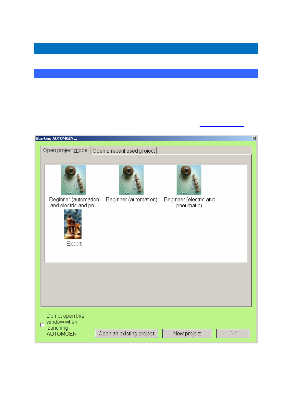
Environment
Environment
Start
When AUTOMGEN is launched, a choice of mode for the environment is
proposed. “Beginner” modes make it possible to start using AUTOMGEN
in a “simplified” configuration, with a reduced number of options in the
menus and simplified palettes. This mode is especially suited to people
using AUTOMGEN for the first time. Expert mode offers all of the
applications. You could create your own models (see “
project models”).
AUTOMGEN8 18 ©opyright 1988-2007 IRAI
Page 21
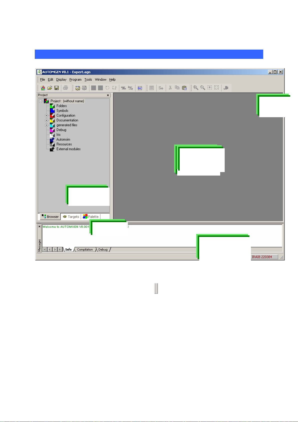
Environment
General views
Tool
bars
Workspace
Browser
Tabs
Message
window
AUTOMGEN’s main window in “Expert” mode
The environment is fully customizable. The tool bars can be moved (by
dragging their moving handle
) and parameterized (menu
“Tools/Customize the environment”).
The state of the environment is saved when you quit it. This state can
also be saved in a project file (see the project options).
AUTOMGEN8 19 ©opyright 1988-2007 IRAI
Page 22
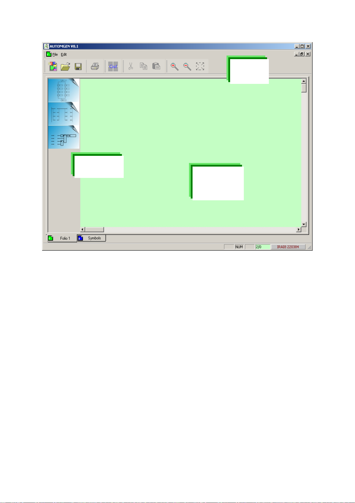
Environment
p
Tool
bars
Simplified
alettes
Workspace
AUTOMGEN’s main window in “Beginner” mode
AUTOMGEN8 20 ©opyright 1988-2007 IRAI
Page 23
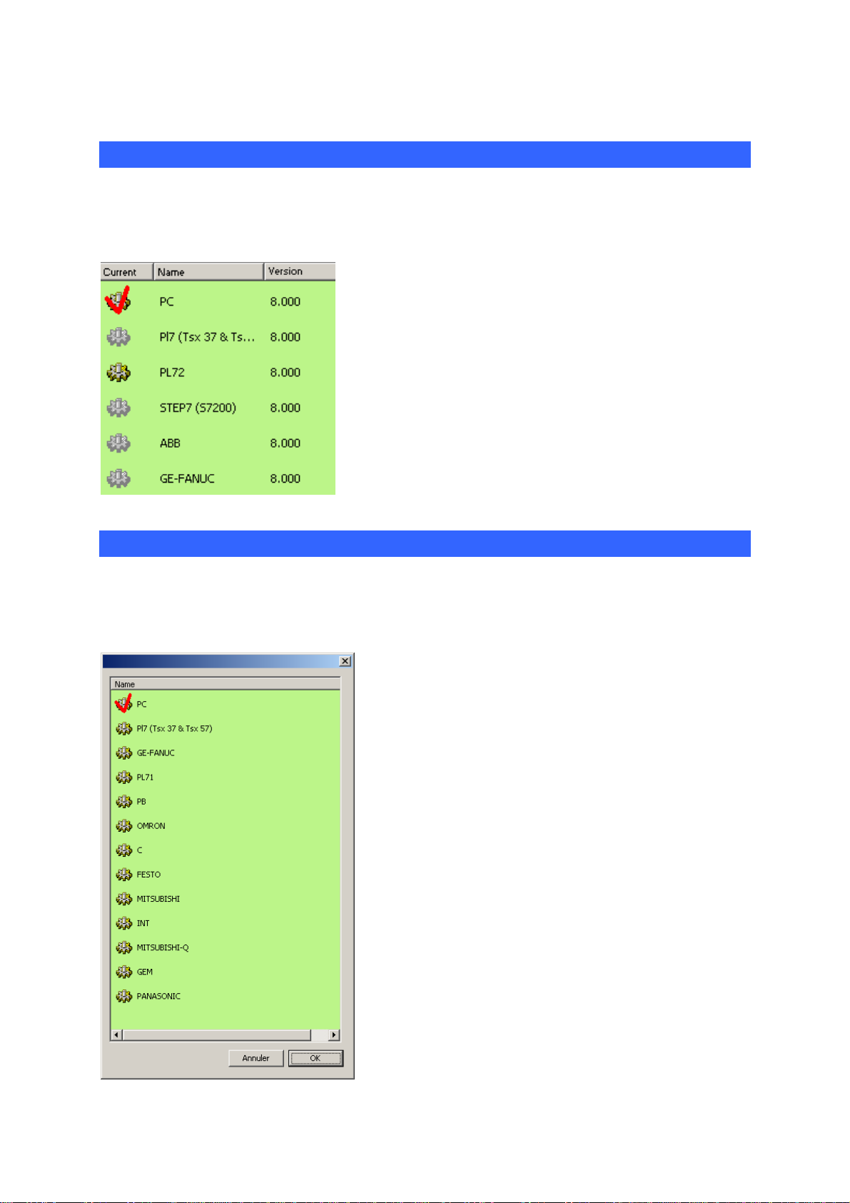
Environment
Selecting targets in expert mode
At the bottom of the browser window there is a “Targets” tab, allowing
access to the list of post-processors installed.
The active target is indicated with a red tick. Access
to targets displayed in grey is not authorized for the
license installed (see the “Licenses” chapter for
more details). To change the current target, doubleclick on the corresponding line. The targets shown in
this list are the ones selected at installation time. If
the target you want to use is not shown in this list,
re-launch the AUTOMGEN installation and install it.
Selecting targets in beginner mode
In beginner mode, the following window is opened to allow the target to
be selected each time a program is run.
AUTOMGEN8 21 ©opyright 1988-2007 IRAI
Page 24
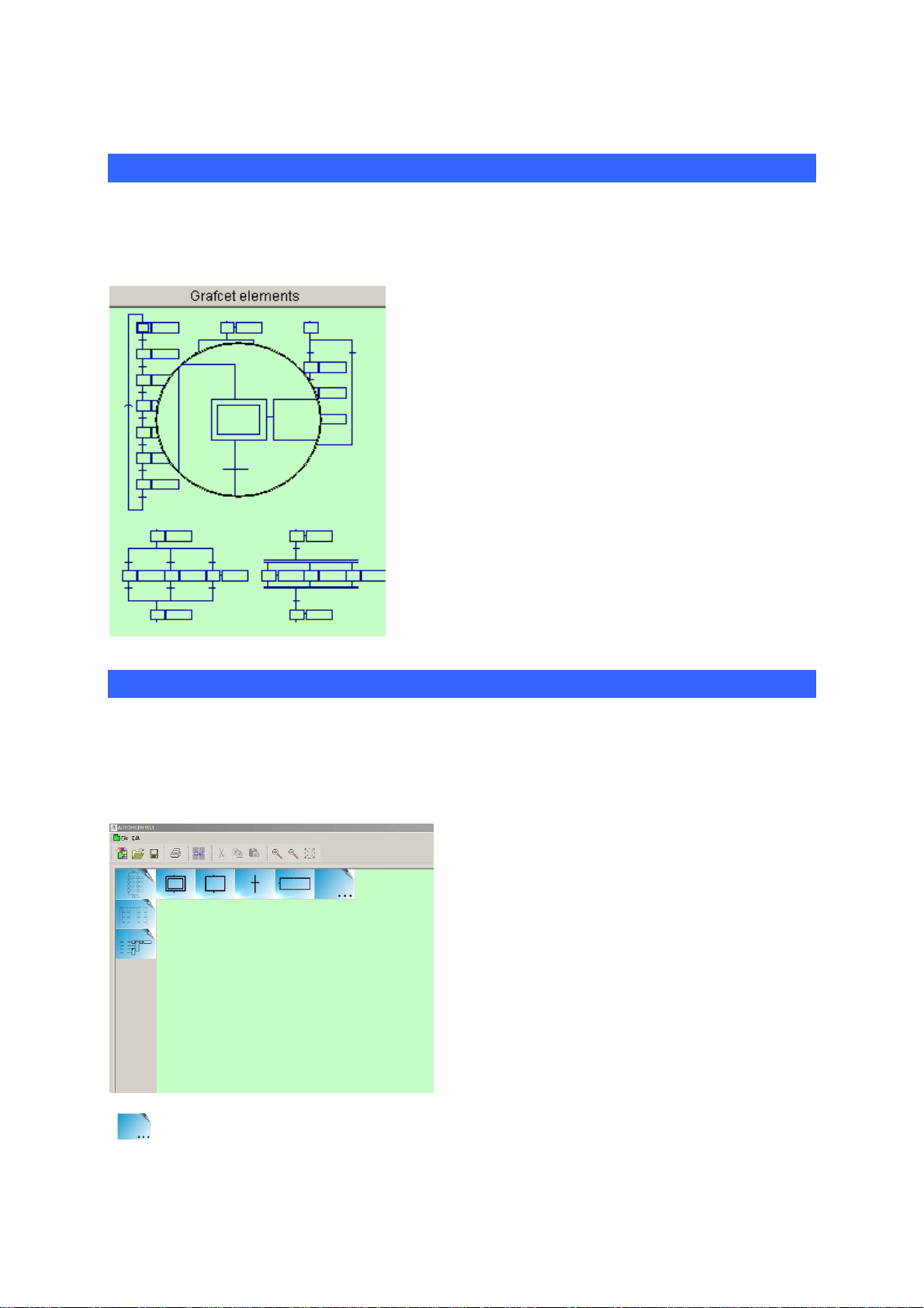
Environment
Palettes in expert mode
At the bottom of the browser window there is a “Palette” tab, allowing
access to program design elements.
The palette gives a set of elements that can be
selected and placed on the sheets. To select an
element, left-click with the mouse in the palette,
expand the selection, release the mouse button,
click in the area selected and move the area
towards the sheet.
The palette also contains the list of symbols for
the project. You can grab them and drag them
onto a test or an action on a sheet.
A magnifying glass is automatically shown when
the elements displayed are small.
Palettes in beginner mode
In beginner mode, the palette contains a reduced group of the simplest
tools for designing programs. Left-click with the mouse over a category
to “open up this category” like a tree structure.
The palette in “beginner” mode
“ ” elements allow access to sub-elements.
AUTOMGEN8 22 ©opyright 1988-2007 IRAI
Page 25
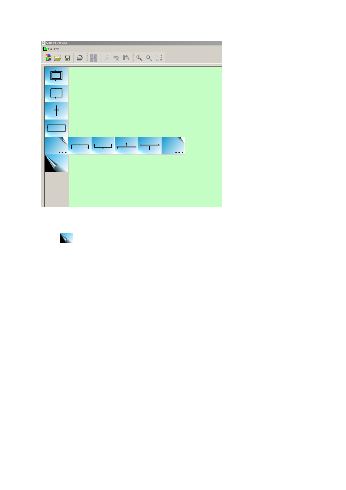
Environment
The palette in “beginner” mode showing the “Grafcet” category open
The “ ” element allows a category to be closed.
AUTOMGEN8 23 ©opyright 1988-2007 IRAI
Page 26
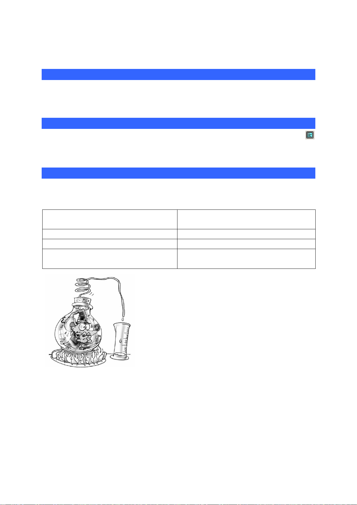
Environment
Displaying or hiding the project window or message window
Select the « Project » or « Messages » option from the « Window »
menu.
Displaying the work space in full screen mode
Select the « Full screen » option from the « Display » menu. Click on
to exit full screen mode.
Keyboard shortcuts
Keyboard shortcuts are written in the menus. « Masked » shortcuts can
also be used:
CTRL + ALT + F8 Save the project in executable
format
CTRL + ALT + F9 Save the project
CTRL + ALT + F10 Access project properties
CTRL + ALT + F11 Display or hide AUTOMGEN
window
Parameters can be set for the entire
environment, its state is saved when you
close AUTOMGEN. Environment windows
can be hidden. The « Windows » menu is
used to display them again. The work space
can be displayed in full screen mode. The
tabs at the bottom of the browser window are
used to access selection for the current postprocessor and the graphics palette.
AUTOMGEN8 24 ©opyright 1988-2007 IRAI
Page 27
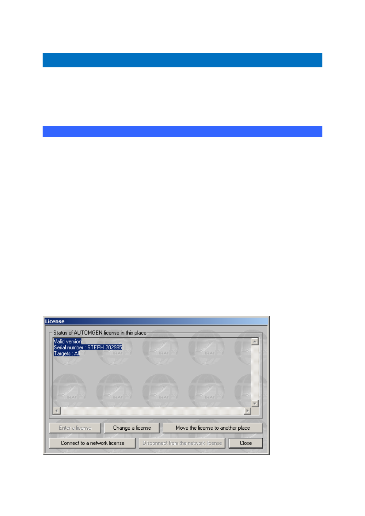
Environment
Licenses
A license establishes AUTOMGEN user rights. The following elements
are established by license:
- the number of all or none inputs/outputs that can be used,
- post-processors that can be used,
- the number of users (only for network licenses).
Registering a license
When you install AUTOMGEN, you can use it for free for a period of 40
days.
You must register your license within 40 days.
To register your license, send IRAI:
- the serial number printed on the label glued to the software box, or
the reference of your delivery note or order form,
- the user code provided with the software indicating the PC where
you have installed the product.
You will then receive an enable code (also called validation code).
The « License » option in the AUTOMGEN « File » menu can be used to
display the status of your license and obtain a user code (click on
« Registering the license »).
License status.
AUTOMGEN8 25 ©opyright 1988-2007 IRAI
Page 28
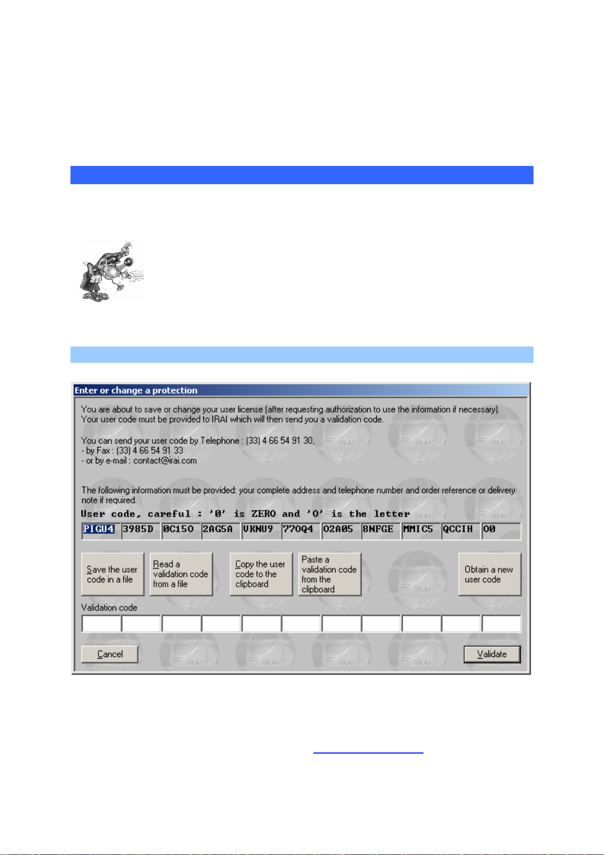
Environment
A user code is valid for a period of 10 days.
So a maximum period of 10 days can pass from when you send a user
code to IRAI and when you receive an enable code provided by IRAI.
Sending a user code to IRAI
There are various methods you can use. Exchanging codes by e-mail is
highly recommended as it limits the risk of error.
A single error in the code will prevent the license from
being registered.
Sending a file by e-mail (the best solution)
License registration dialogue box
To generate a file containing your user code, click on « Save user code
in a file ». You can then transmit the file with « .a8u » extension as an
attachment and send it to the address
contact@irai.com.
AUTOMGEN8 26 ©opyright 1988-2007 IRAI
Page 29

Environment
Copying the user code in an e-mail message
By clicking on « Copy user code to clipboard », you can then paste the
code in the body of the message and transmit it to the e-mail address
contact@irai.com.
By fax (not recommended)
By clicking on « Copy user code to clipboard », you can then paste the
code in a document and send it by fax to 00 33 4 66 54 91 33. If possible
avoid writing the code by hand and print it using a font which
differentiates between the letter « O » and the number zero.
By telephone (highly unadvisable)
By telephoning 00 33 4 66 54 91 30. Be sure to differentiate between the
letter « O » and number zero. Be careful of consonants which are difficult
to tell apart on the telephone (for example « S » and « F »).
Entering the validation/enable code
Validating by a e-mail received file
If you have received an « .a8v » file by e-mail, save the file on your hard
disk, click on « Read a validation code from a file » and select the file.
Validating for a code received in the text of an e-mail
Select the code in the message text (make sure you only select the code
and do not add any spaces to the end). Click on « Paste a validation
code from the clipboard ».
Validating for a code received by fax or telephone
Enter the code in the spaces under the title « Validation code ».
Modifying a license
Modification of a license Involves changing the elements authorized by
the license (for example adding a post-processor).
The license modification procedure is identical to registration.
AUTOMGEN8 27 ©opyright 1988-2007 IRAI
Page 30
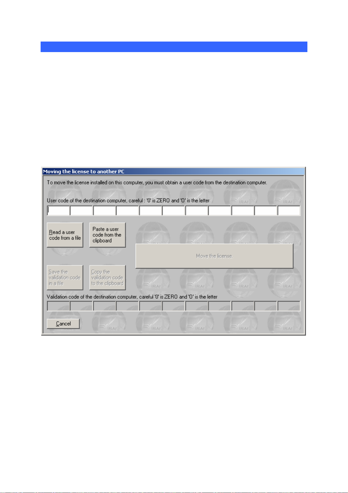
Environment
Moving a license from one computer to another
This procedure is more complex. The instructions below must be
scrupulously followed to obtain good results. In the instructions below,
« source » PC indicates the computer with the license and the « target »
PC is the PC where the license needs to be moved.
1- if it has not already been done, install AUTOMGEN on the target
PC,
2- generate an « .a8u » user code file on the target PC and move this
file to the source PC (for example on a floppy disk),
3- on the source PC, select the « Move the license to another place »
option,
Dialogue box for moving a license
4- on the source PC, click on « Read a user code from a file » and
select the « .a8u » file that came from the target PC,
5- on the source PC, click on « Move the license »,
6- on the source PC, click on « Save the validation code in a file »,
recopy the generated « .a8v » file to the target PC,
7- on the target PC, click on « Read a validation code from a file »
and select the « .a8v » file that came from the source PC.
AUTOMGEN8 28 ©opyright 1988-2007 IRAI
Page 31

Environment
Network licenses
The « akey8.exe » executable manages the network license. This
executable must be launched from one of the network computers. The
network must be able to be used with TCP IP protocol. When launched,
the network license manager is hidden and only a
WINDOWS keybar. To display the network license manager window,
double click on the
icon in the keybar.
icon appears in the
The network license manager
Up to 16 different licenses can be managed by the network license
manager. A network license is characterized by a number of users and a
type of copyright (number of all or none inputs/outputs and useable postprocessors). For each license the number of possible user/s, number of
connected user/s and list of connected users (using AUTOMGEN) is
AUTOMGEN8 29 ©opyright 1988-2007 IRAI
Page 32

Environment
displayed in a tree format attached to each license. Each license is
associated to a port number (a numeric value starting from 5000 by
default). The first port number used can be configured by clicking on
« Parameters ».
Adding a network license
You can add a license by clicking on « Add a license ». The license
registration principle is the same as for single license versions.
Modifying a license
Double click on the licenses to modify them. The license modification
procedure is the identical to that used for single license versions.
Connecting to client stations
Click on « Connect to a network license » to connect a client station to a
network license.
Connecting to a network license
The PC name (the one from the network) where the « akey7.exe » was
launched must be provided as well as the port number corresponding to
the desired license.
You must register your license with IRAI
contact@irai.com) by sending your user
(
code by e-mail (« File/License » menu. The
network license manager is used to manage
multiple licenses on TCP IP network PC's.
AUTOMGEN8 30 ©opyright 1988-2007 IRAI
Page 33

Environment
Additional information on installing AUTOMGEN in a network environment
General information
Two aspects of the AUTOMGEN
installing files on the one hand and managing licenses on the other.
These two aspects are completely separate: you can choose to install
the files either on the hard disk of the client PCs or else on a file server
and, completely independently of this, choose to install either a license
locally on a PC or else a network license on a network license manager.
8
installation have to be considered:
Installing AUTOMGEN8 on a file server
Benefit: the AUTOMGEN
8
files are installed just once on a file server,
and updates are simplified.
Procedure on the file server: install AUTOMGEN
8
. Rights needed: read-
access is sufficient.
Procedure on the client workstations: create a shortcut to the
“autom8.exe” executable, which is in the AUTOMGEN
8
installation
directory on the file server.
Installing one or more AUTOMGEN licenses on a network license
8
manager
Benefit: the licenses are no longer restricted to one PC but can be used
by all of the PCs connected to the network (floating licenses).
Principle: one or more licenses are installed on one of the network’s
PCs. A license authorizes from 1 to n users. AUTOMGEN
8
may be
launched on client PCs upto the maximum number of users. A license
has the same features for all users in terms of the number of
inputs/outputs that can be used and the types of post-processors that
can be used. If several configurations (several types of licenses) are
AUTOMGEN8 31 ©opyright 1988-2007 IRAI
Page 34

Environment
needed, then as many licenses will be created as there are different
types of configurations. When AUTOMGEN
8
is launched on the client
PCs, a connection will be created to one or other of the licenses
depending on the features that are wanted.
Actual example: setting up a network of 4 16 I+16 O PL72 licenses, 4 16
I+16 O PL7 licenses + 2 unlimited I/O PL7 licenses. For this: 3 licenses
will be created on the network license manager: 1 license for 4 16 I+16 O
PL72 users, 1 license for 4 16 I+16 O PL7 users, 1 license for 2 unlimited
I/O PL7 users.
Where to install the network license manager: on one of the network’s
PCs (it does not have to be the server) which must be running all the
8
time (whenever a user would like to use AUTOMGEN
).
Technical constraints: the network must support TCP/IP, the PC where
the network license manager is located must be able to run a WINDOWS
program (application or service).
Installation on the network license manager: on the PC where the
network licenses are going to be managed, install the main
8
AUTOMGEN
module + the network license manager.
Registering one or more licenses on the network license manager:
launch the network license manager: (AKEY8.EXE executable, located in
8
the AUTOMGEN
installation directory). When launched, the license
manager sets up an icon in the bottom right of the WINDOWS task bar.
Left-click once with the mouse to open the window.
Click on “Add a license” to add a license.
Click on “Save the user code in a file” to generate an .n8u file that you
will e-mail to us at the address “contact@irai.com”: we will send back an
.n8v file that you will connect up by clicking on the “Read a validation
code from a file” button.
The licenses installed in this way will then be shown in the network
license manager with the serial number and characteristics of the license
and the associated port number. It is this port number that will allow
clients to connect to a specific license.
AUTOMGEN8 32 ©opyright 1988-2007 IRAI
Page 35

Environment
Installation on the client workstations: launch AUTOMGEN , and in the
8
“File / License” menu select “Connect to a network license”.
Enter the name of the PC where the network license manager is running
(or its IP address) and the port number (this number makes it possible to
identify the license you want to connect to, if there is more than one).
It is also possible to add an argument in the AUTOMGEN
8
launch
shortcut in order to force connection to one network license.
The argument is:
/NETLICENSE=<name of the PC where the network license manager is
located>,<port>
Make sure that “NETLICENSE” is correctly spelled: S not C at the end.
For example:
/NETLICENSE=MYSERVER,5001
Several launch shortcuts can be created in order to connect to different
licenses.
Possible problems: if you use a firewall, make sure access is authorized
to the ports used by the network license manager (those displayed in the
network license manager).
Installing the network license manager as a service under WINDOWS
NT, 2000, XP, 2003 and VISTA:
see the following chapter.
Displaying the status of the licenses remotely: to display the status of the
network license manager on a different PC from the one on which the
network license manager has been launched (or if the “service” version
of the network license manager is being used), use the
8
“spya8protnet.exe” utility, which is located in the AUTOMGEN
installation directory.
Installing the network license server as a service
The “NT Service” key server allows the AUTOMGEN
8
network licenses
to be managed on a WINDOWS NT4, 2000, 2003, XP or VISTA
AUTOMGEN8 33 ©opyright 1988-2007 IRAI
Page 36

Environment
workstation without opening a session. Unlike the AKEY8.EXE
“executable” version, AKEY8NT.EXE does not allow either the
protections or the connected users to be displayed.
Before installing the key server as an “NT service”, you are
recommended to make sure that the key server works properly with the
“executable” version: AKEY8.EXE.
Launch the “akey8nt –i” command line to install the NT key server
service. The AKEY8NT.EXE executable is installed in the AUTOMGEN
installation directory.
So that the service starts automatically:
- under WINDOWS NT4: in the “Start/Parameters/Configuration
Panel” menu, select the “Services” icon the “AKEY8” line, click on
the start button and select the “Automatic” button.
Reboot your PC so that the key server is activated.
- under WINDOWS 2000, 2003, XP or VISTA: in the
“Start/Parameters/Configuration Panel” menu, select the
“Administrative Tools” icon then the “Services” icon. Right-click with
the mouse on the “AKEY8” line and select “properties”. In the
“Startup Type” option, select “Automatic”. In the “Recovery” tab,
select “Restart the service” in the “First Failure” area.
Uninstallation
Launch the “akey8nt –u” command to uninstall the NT key server
service.
Errors
After having uninstalled the AKEY8NT.EXE service, use AKEY8.EXE to
determine the cause of any malfunctions.
AUTOMGEN8 34 ©opyright 1988-2007 IRAI
Page 37

Environment
The project
AUTOMGEN
8
is strongly based on the idea of a project. A project groups
together the elements that compose an application. The browser (see
page Erreur ! Signet non défini.) displays all the project elements
(sheets, symbols, configuration, IRIS objects etc.) in a tree format.
The new file format of AUTOMGEN
8
(files with « .AGN » extension)
includes all project elements.
When you save an « .AGN » file you are assured of saving all the
elements of an application. You can easily and effectively interchange
applications created with AUTOMGEN.
« .AGN » files are compacted with « ZIP » technology, they do not need
to be compressed to be interchanged, their size is already optimized.
All the files generated by AUTOMGEN
8
versions of AUTOMGEN
: upward and downward compatibility.
8
can be re-read with all of the
Files generated with AUTOMGEN
The files created with AUTOMGEN can be opened directly in
AUTOMGEN
8
.
7
7
Importing an application from an earlier version of AUTOMGEN (version 6 or earlier)
You need to import all of the sheets (“.GR7” files) and any symbol file
(“.SYM” file). To do this, use the import procedures described in the
following chapters.
Generating a free distribution executable file
The « Generate an executable » command from the « File » menu
is used to generate an executable starting from a project in
progress (an « .EXE » file executable on a PC with WINDOWS).
The AUTOMGEN « viewer » is automatically integrated with the
generated executable (the executable user does not need
AUTOMGEN). This viewer makes it possible to use the
application without modifying it. You can easily distribute your
AUTOMGEN8 35 ©opyright 1988-2007 IRAI
Page 38

Environment
applications. The generated executable is not covered by
copyright. This technique is normally used for producing a
supervising application.
Modifying project properties
With the right side of the mouse click on the « Project» element on the
browser and select « Properties » from the menu.
Modifying security options
You can restrict reading or modification access to a project by
passwords.
Advanced options
« Save the environment aspect with the project »: if checked, the position
of the windows and the aspect of the toolbars are saved in the « .AGN »
file. When the project is opened, these elements are reproduced.
« Hide the main window upon launching … »: if checked, the
AUTOMGEN window is hidden when the project is opened. Only IRIS
objects incorporated in the project will be displayed. This option is
normally used to create « package » applications which only leave IRIS
objects displayed. Use the [CTRL] + [F11] keys to redisplay the
AUTOMGEN window.
The other options are used to change the display of the AUTOMGEN
window when a project is opened.
User interface
« Block IRIS object configuration »: if checked, a user cannot modify
IRIS object configuration.
The other options are used to modify the behavior of the user interface.
Model
« This project is a document model »: if checked, when opened all the
options and the documents it contains act as a model for the creation of
a new project. This functionality is used to create standard configuration
which can be uploaded when AUTOMGEN is launched (for example a
default symbol file or a default processor configuration).
Defining a mode
To define a mode that can be used when launching AUTOMGEN (like
the “Expert” and “Beginner” modes), save a project model in the
AUTOMGEN8 36 ©opyright 1988-2007 IRAI
Page 39

Environment
“models” sub-directory of the AUTOMGEN installation directory. An
image can be linked to a model. To do this, create a “jpg” format file with
the same name as the “.agn” file. This file must have the following
dimensions: 120 pixels wide by 90 pixels high.
Automatic GO
«Automatic go at project launch »: if checked, the application is
automatically run when a project is opened.
The project is used to group together the
elements of an AUTOMGEN application.
Once regrouped, the elements form a
compact file with « .AGN » extension. The
project models are used to be able to easily
manage different software configurations.
Generation of executables makes it easy to
distribute applications.
AUTOMGEN8 37 ©opyright 1988-2007 IRAI
Page 40

Environment
The Browser
A central element for application
management, the browser is used for
fast access to different application
elements: sheets, symbols,
configuration, printing, IRIS objects etc.
The « + » and « - » icons are used to
develop or retract project elements.
Actions on the browser are effected by
double clicking on the elements (opens
the element) or by clicking with the right
side of the mouse (adds a new element
to a project, special action on an
element etc.).
Certain operations are effected by
dragging and dropping the elements and
moving them on the browser.
The colors (generally called up at the
bottom of documents in the work space)
are used to identify families of elements.
Browser tree
AUTOMGEN8 38 ©opyright 1988-2007 IRAI
Page 41

Environment
Sheets
A sheet is a page where a program or part of a program is designed.
Using sheets is extremely simplified in AUTOMGEN
chaining orders needed in the previous versions are no longer used. For
multiple sheets to be compiled together, they only need to be in the
project.
The icons associated to the sheets are shown below:
-
-
-
normal sheet,
normal sheet (excluding compilation),
sheet containing a macro-step expansion,
- sheet containing a function block program,
-
-
-
sheet containing a key,
sheet containing a key (excluding compilation).
sheet containing an encapsulation,
Icons are marked with a cross indicating a closed sheet (not displayed in
the work space). Double clicking on this type of icon opens (displays) the
associated sheet.
8
. The sheet
Adding a new sheet
With the right side of the mouse click on the « Sheets » element on the
browser then select « Add a new sheet ».
Select the sheet size (XXL is the
recommended format, the other
formats are for older versions of
AUTOMGEN, GEMMA is only
used for creating GEMMA
models).
The sheet can be given any
name, but each project sheet
must have its own name.
The comment area is up to your
discretion for modifications or
other information relative to each
sheet.
AUTOMGEN8 39 ©opyright 1988-2007 IRAI
Page 42

Environment
Importing old AUTOMGEN version sheets, importing CADEPA sheets
With the right side of the mouse click on the « Sheets » element on the
browser then select « Add one or more existing sheets ».
Selecting one or more sheets to import.
From the « Type » list select « AUTOMGEN » or « CADEPA » for the
sheet type to import then click on OK.
There are some restrictions for importing
CADEPA sheets:
- the step numbers must be individual (the
same step number cannot be used on
multiple sheets),
- references must be converted with links to
CADEPA before being able to import
them.
By keeping the [CTRL] key pressed down, you can select multiple
sheets.
Modifying the sheet compilation order
The sheets are compiled in the order they are listed in for the project. To
modify this order, click on the sheet with the left side of the mouse on the
browser and move it in the list.
AUTOMGEN8 40 ©opyright 1988-2007 IRAI
Page 43

Environment
Deleting a sheet from the list
With the right side of the mouse click the sheet to be deleted on the
browser and select « Delete » from the menu.
Exporting a sheet to a « .GR7 » file
With the right side of the mouse click the sheet to be deleted on the
browser and select « Export » from the menu.
Copying, Cutting, Pasting a sheet
With the right side of the mouse click the sheet on the browser and
select « Copy/cut » from the menu. To paste, with the right side of the
mouse click on the « Sheet » element on the browser and select
« Paste ».
This option makes it possible to copy or transfer sheets from one project
to another.
Renaming a sheet
See « Modifying properties » below.
Modifying sheet properties.
With the right side of the mouse click the sheet on the browser and
select « Properties » from the menu.
AUTOMGEN8 41 ©opyright 1988-2007 IRAI
Page 44

Environment
You can modify the
sheet name, the syntax
used for literal
language and variable
names. The « Do not
compile this sheet »
option is used to
exclude the sheet from
the compilation. The
« Display in GEMMA
format» option is only
available if the sheet
format is GEMMA and
is used to display and
modify a sheet in
GEMMA format. The
« Block the of use
inputs/outputs other
than set symbols »
option blocks the use of
i, %i, o %q variables
not attributed to
symbols. Access to the
sheet can be protected
by a password. -The
« comments » area is
left to your discretion.
Symbols
The list of symbols provides the correspondence between « symbol »
names and variable names. A project may only have one symbol table.
Creating a symbol table
With the right side of the mouse click on the « Symbols» element on the
browser and select « Create a symbol table » from the menu.
Importing a symbol table
With the right side of the mouse click on the « Symbols» element on the
browser and select « Import a symbol table » from the menu.
AUTOMGEN8 42 ©opyright 1988-2007 IRAI
Page 45

Environment
Configuration
Post-processors
This section contains all the post-processor configuration elements (see
the post-processor manual for more information).
Compiler options
Double click on this element to modify the settings of compiler options.
Documentation
This is used to access the file printing function (double click on the
« Print » element. You can print a complete file composed of an end
paper, cross reference table, symbol list and sheets. The print setup
function is used to display all these elements.
AUTOMGEN8 43 ©opyright 1988-2007 IRAI
Page 46

Environment
Generated files
Generating the instruction list in pivot code
By double clicking on « Pivot code » you generate a list in low level literal
language (AUTOMGEN pivot code). Viewing of the generated code is
normally reserved for specialists involved in understanding the
translation methods used by the compiler.
Generating the cross reference list
Double clicking on the « Cross reference » element generates and
displays the list of variables used in an application with any associated
processor variables and the name of or sheet(s) where they are used.
Post-processors
The other elements concern the files generated by the post-processors:
instruction lists are in processor language.
Settings
Contains the tools to display and modify the state of the variables.
Viewing and modifying a variable or variable table
With the right side of the mouse click on « Settings » and select
« Monitoring » to open an element where you can see the state of a
variable or variable table.
A monitoring window.
Next variable
Previous
variable
Select a
variable
Modify the state
of another
variable
Close
Open the
menu
AUTOMGEN8 44 ©opyright 1988-2007 IRAI
Page 47

Environment
Modify the
variable state by
clicking in this
area
The monitoring window in « 10 variables table » mode.
Click on this button to display
the expanded information
(automaton symbols and
names of variables)
associated with each variable
The monitoring window in “Variables Table” mode
Click on these buttons
to change the size of
the information
displayed in the table
Re-size the window by
dragging one of the
edges in order to see
more or fewer variables
AUTOMGEN8 45 ©opyright 1988-2007 IRAI
Page 48

Environment
IRIS objects
IRIS 2D objects are used to create consoles, supervision applications
and simulation applications of 2D operating parts. IRIS 3D is used to
create simulation applications of 3D operating parts. Each IRIS 2D object
appears in the project tree (see the chapters
IRIS 3D references for additional information).
Adding an IRIS 2D object
Click with the right side of the mouse on « Add an IRIS 2D object ». The
object selection assistant is used to select it and set its parameters.
IRIS 2D references and
Selection assistant for an IRIS 2D object
AUTOMGEN8 46 ©opyright 1988-2007 IRAI
Page 49

Environment
Deleting an IRIS 2D object
With the right side of the mouse click on the IRIS object on the browser
and select « Delete » from the menu.
Displaying or hiding an IRIS 2D object
With the right side of the mouse click on the IRIS object on the browser
and select « Display/hide » from the menu.
Cutting, copying, pasting an IRIS 2D object
With the right side of the mouse click on the IRIS object on the browser
and select « Copy » or « Cut » from the menu.
To paste, with the right side of the mouse click on the « Sheet » element
on the browser and select « Paste ».
To paste an IRIS object on a console, select « Paste» from the console
menu or click with the right side of the mouse on the console on the
browser and select « Paste».
Adding a new IRIS 2D object on a console
Select « Add an object » from the console menu or click with the right
side of the mouse on the console on the browser and select « Add an
object on the console » from the menu (for more information on the
console see the chapter
« Console » object)
Modifying the properties of an IRIS 2D object
With the right side of the mouse click on the IRIS object on the browser
and select « Properties ». For higher level objects (parent objects),
special properties can be accessed:
AUTOMGEN8 47 ©opyright 1988-2007 IRAI
Page 50

Environment
Properties of high level objects
Display establishes under which conditions the object is displayed or
hidden. The reinstallation option is used to return an object to its initial
state when dynamic display is launched (normally used for OP simulation
applications).
Setting an object model accessible on the assistant
With the right side of the mouse click on the IRIS object on the browser
and select « Save as model » from the menu.
AUTOMGEN8 48 ©opyright 1988-2007 IRAI
Page 51

Environment
Selection of modifiable parameters for users of your models
You can select the list of parameters which remain accessible to the user
on the assistant. By clicking on « Save », you save your object model.
The storage directory for object models is « <AUTOMGEN installation
directory>\i2d\lib ». You can use a sub-directory called « my objects » for
saving your models.
Importing an IRIS 2D object in an earlier version of AUTOMGEN
With the right side of the mouse click on the « IRIS» element on the
browser and select « Import IRIS 2D objects ». Select one or more
« .AOF » files.
Creating an IRIS 3D console
With the right side of the mouse click on the « IRIS » element on the
browser and select « Add an IRIS 3D console » (see the chapter on IRIS
3D for more information).
AUTOMGEN8 49 ©opyright 1988-2007 IRAI
Page 52

Environment
Resources
This project element is used for adding all types of files to a project. Files
which are added will become an integral part of the project and will be
saved along with the other elements. To refer to a pseudo directory
where the resources are, the key word « <RESDIR> » can be used in the
specific directory name in AUTOMGEN. For example IRIS objects can
refer to bitmaps if they are included in the resources.
Adding a file to the resources
With the right side of the mouse click on the « Resources» element on
the browser and select « Add » from the menu.
Deleting a file from the resources
With the right side of the mouse click the resource file on the browser
and select « Delete ».
Renaming a file in the resources
With the right side of the mouse click the resource file on the browser
and select « Rename ».
Modifying a file in the resources
With the right side of the mouse click the resource file on the browser
and select « Modify ».
Adding and converting 3D STUDIO files in the resources
3D STUDIO files can be converted into .x files and added to the
resources by clicking with the right side of the mouse on the
« Resources » element on the browser and selecting « Import 3D files »
(see the chapter
IRIS 2D references and IRIS 3D references for more
information).
External modules
These elements are reserved for executable modules developed by third
parties and interfaced with AUTOMGEN.
AUTOMGEN8 50 ©opyright 1988-2007 IRAI
Page 53

Environment
The browser is used to display and manage
all the project elements. By double clicking
on the elements or by clicking with the right
side of the mouse, you access the different
functions applicable to each element.
AUTOMGEN8 51 ©opyright 1988-2007 IRAI
Page 54

Environment
Designing programs
Various tools are available for designing programs.
Designing with the assistant
This is without doubt the simplest when starting with AUTOMGEN. With
the right side of the mouse click on an open sheet in the work space and
select « Assistant » from the menu. You will then be guided for making
selections. When you have finished click on « OK » and put the design
on the sheet by clicking with the left side of the mouse.
The assistant
AUTOMGEN8 52 ©opyright 1988-2007 IRAI
Page 55

Environment
Designing with the shortcut menu
Click with the right side of the mouse on an open sheet in the work
space, the menu will propose a series of elements that you can put on
the sheet. This is an instinctive and fast creation method.
Designing with the pallet
By selecting elements on the pallet you can quickly create programs
starting from previously created elements.
Enhancing and customizing the pallet
« .GR7 » files are used to set the pallet, they are located in the directory
« <AUTOMGEN installation directory>\pal ». You can delete, modify,
rename or add files. To generate « .GR7 », files use the « Export »
command by clicking with the right side of the mouse on a sheet on the
browser. The names displayed on the pallet are « .GR7 » files. Relaunch
AUTOMGEN for a new element to be displayed on the pallet.
Designing with the keyboard keys
Each key is associated to design blocks. The « Blocks » element also
provides access to the blocks. The table below lists the blocks and their
use.
Delete block
Aspect Associated key Generic name Comments Languages
[A] Delete
Link blocks
Aspect Associated key Generic name Comments Languages
[E] Vertical link
Used to make a cell blank
again
Link from top to bottom
or bottom to top
All
All
AUTOMGEN8 53 ©opyright 1988-2007 IRAI
[F] Horizontal link
Link from right to left or
left to right
All
Page 56

Environment
[G] Upper left corner All
[H] Upper right corner
[I] Lower left corner All
[J] Lower right corner
[Z] Cross Crosses two links All
Link towards the bottom
right or bottom left
Link towards the bottom
left or bottom right
Link from top to right or
left to top
Link from top to left or
right to top
All
All
Grafcet blocks
Aspect Associated key Generic name Comments Languages
[B] Step Normal step Grafcet
[C] Grafcet
[D] Initial step Initial step Grafcet
Macro-step
Initial step without
activation
[+] Encapsulating step
.
[-] Initial encapsulating step
.
Initial state mark Grafcet
.
[T] Transition Transition Grafcet
[$] Source transition
.
Initial step without
activation
Only available in the
shortcut menu
An encapsulation must
be linked
An encapsulation must
be linked
Défine intial state for an
encapsulation
Can replace the
transition symbol
Grafcet
Grafcet
Grafcet
Grafcet
[£] Exit transition
Can replace the
transition symbol
Grafcet
AUTOMGEN8 54 ©opyright 1988-2007 IRAI
Page 57

Environment
Grafcet
Link for action on
transition crossing
.
Grafcet
.
[K] Grafcet
Start of an action
rectangle on transition
crossing
Left limit of an « And »
divergence
Use the following
element to design the
action rectangle
Use the [X] and [Y]
elements to end the
rectangle
Compulsory to the left
of an « And »
divergences
[L] Grafcet
Supplementary branch
of an « And »
divergence or an
Do not use as a left or
right limit of an « And »
divergence
« And » convergence
[M] Grafcet
Right limit of an
« And » divergence
Compulsory to the right
of an « And »
divergence
[N] Grafcet
Extension of an « And »
divergence
If placed in the [K], [L],
[M], [P] or [O],[P],[Q],
[L] blocks
[O] Grafcet
Left limit of an « And »
convergence
Compulsory to the left
of an « And »
convergence
[P] Grafcet
Supplementary branch
of an « And »
convergence or an
Do not use as a left or
right limit of an « And »
convergence
« And » divergence
[Q] Grafcet
Right limit of an
« And » convergence
Compulsory to the right
of an « And »
convergence
[R] « Or » divergence Grafcet
[S] « Or » convergence Grafcet
Do not use as a limit of
an « Or » convergence
Do not use as a limit of
an « Or » divergence
[U] Skip or repeat left step Grafcet
[V] Skip or repeat right step Grafcet
« Or » convergence or
divergence
« Or » convergence or
AUTOMGEN8 55 ©opyright 1988-2007 IRAI
Page 58

Environment
divergence
[SPACE] on an
[E] block
Link towards the top Grafcet
For relooping and
repeating steps
Flowchart blocks
Aspect Generic name Comments Languages
Associated
key
[0] (zero) Flowchart assignment Flowchart
[1] « Not » function Flowchart
[2] « And » function Flowchart
[3] « Or » function Flowchart
Separates the « test »
from the « action »
area
Complements the
block input signal
Combines the inputs in
an « And » logic
Combines the inputs in
an « Or » logic
[4] Block environment
[5] Bottom of block Flowchart
Enlarges an « And » or
« Or » function block
Ends an « And » or
« Or » function block
Flowchart
Ladder blocks
Aspect Associated key Generic name Comments Languages
[(] Start left coil Starts an action Ladder
[)] Start right coil Ends an action Ladder
[U] Left limit Ends the diagram Ladder
[V] Right limit Starts the diagram Ladder
[R] Connection « Or » function Ladder
AUTOMGEN8 56 ©opyright 1988-2007 IRAI
[S] Connection « Or » function Ladder
Page 59

Environment
Action blocks
Aspect Generic name Comments Languages
Associated
key
[W] Starts an action Grafcet and Flowchart
[X] Extends an action Grafcet and Flowchart
[Y]
[.]
.
[/] Grafcet and Flowchart
.
[%] Grafcet and Flowchart
.
Action rectangle left
limit
Action rectangle
environment
Action rectangle
right limit
Left side of a
double action
rectangle
Middle of a double
action rectangle
Right side of a
double action
Ends an action Grafcet and Flowchart
Starts a double action
Grafcet and Flowchart
rectangle
Prolongs a double
action rectangle
Ends a double action
rectangle
rectangle
[S] Divergence Action
Used to vertically
juxtapose action
Grafcet and Flowchart
rectangles
[V] Divergence Action
Used to vertically
juxtapose action
Grafcet and Flowchart
rectangles
.
[#] Grafcet
Action on
activation
[_] Grafcet
Action on
deactivation
[@] Grafcet
.
Event-driven
action
Defines the type of
action
Defines the type of
action
Defines the type of
action
AUTOMGEN8 57 ©opyright 1988-2007 IRAI
Page 60

Environment
Test blocks
Aspect Generic name Comments Languages
Associated
key
[7] Left limit of a test Starts a test Flowchart and ladder
[6] Right limit of a test Ends a test Flowchart and ladder
Organization chart blocks
Aspect Generic name Comments Languages
Associated
key
[<]
[=] « False » output
Organization chart
input
Indicates the input in a
rectangle
Output if a test
rectangle is false
Organization
chart
Organization
chart
Function block blocks
Aspect Generic name Comments Languages
Associated
key
[8] Function block
[9] Function block
[:] Function block
[;] Function block
[>] Function block
[?] Function block
Upper left corner of a
function block
Upper right corner of a
function block
Lower left corner of a
function block
Left limit of a function
block
Right limit of a
function block
Lower right corner of a
function block
Starts the name of the
function block
Ends the name of the
function block
Adds an input to the
function block
Adds an input to the
function block
Adds an output to the
function block
Adds an output to the
function block
AUTOMGEN8 58 ©opyright 1988-2007 IRAI
Page 61

Environment
Other blocks
Aspect Generic name Comments Languages
Associated
.
key
[*]
Combination /
transition link
This block is a link
between the Logical
Diagrams or Ladder
languages and the
Grafcet language
Grafcet /
Flowchart /
Ladder
Documenting program elements
To document program elements, click below with the left side of the
mouse. To create comments, click on a blank space on the sheet. To
validate modifications, push the [Enter] key or click outside the editing
are with the left side of the mouse. To delete modifications, push the
[Esc] key or click outside the editing area with the right side of the
mouse.
When editing tests and actions, a « … » button appears under the editing
area. If you click on it you access an assistant for creating tests or
actions.
AUTOMGEN8 59 ©opyright 1988-2007 IRAI
Page 62

Environment
Test creation assistant
Adding symbols
To create a symbol, click with the right side of the mouse on the symbol
table in the work space and select « Add ». Or click the
toolbar. You can also launch program compiling containing unset
symbols. You will be asked for variables corresponding to the symbols
during the compilation.
button on the
AUTOMGEN8 60 ©opyright 1988-2007 IRAI
Page 63

Environment
Attribution of symbols during compilation
To easily design a program, create a new
sheet, then click with the right side of the
mouse on the bottom of the sheet. Select
« Assistant » from the menu, you will then
be guided by it.
AUTOMGEN8 61 ©opyright 1988-2007 IRAI
Page 64

Environment
Running an application
To run an application easily
The
button on the toolbar is the quickest way to see application run
results. This pushbutton activates the following mechanisms:
- compilation of the application if it is not updated (not already
compiled after the last modifications),
- installation of the run module (with downloading if the current target
is a processor and following the connection options),
- passage of the target to RUN,
- activation of the dynamic display.
To end the run
Click on . On the processor target, the program continues to be run
on the target. On the PC, the program is stopped.
To compile only
Click on
.
To stop the compilation
Click on
.
To connect to a processor or install a PC
Click on
.
To disconnect a processor or uninstall a PC
Click on
.
To put the target in RUN mode
Click on
.
To put the target in STOP mode
Click on
.
To initialize the target
Click on
.
AUTOMGEN8 62 ©opyright 1988-2007 IRAI
Page 65
Environment
To run a program cycle on the target (generally not supported on processors)
Click on
.
To activate the dynamic display
Click on
.
To run an application, click on the « GO »
button. To end the run, click again on the
same button.
AUTOMGEN8 63 ©opyright 1988-2007 IRAI
Page 66

Environment
The compiler
The compiler translates the sheets into a set of pivot language equations
(these can be displayed by double clicking on the « Generated code /
pivot language » element on the browser).
The pivot language is then translated into a language which can be run
by a post-processor (the current post-processor can be displayed and
selected by double clicking on the « Targets » panel accessible by
clicking on the « Targets » tab at the lower part of the window where the
browser is.
Modifying compiler options
Double click on the element « Configuration / Compiler options».
Displaying compilation messages
The « Compilation » panel on the messages window contains the counts
produced by the last compilation.
Finding an error
By double clicking on error messages, you can find the source.
An error message and its source
AUTOMGEN8 64 ©opyright 1988-2007 IRAI
Page 67

Environment
If the message windows are hidden and if one or more errors are
detected by the compiler, a dialogue box indicates the first error detected
(to display the message windows: use the « Messages » command from
the « Windows » menu).
At the end of the compilation the
« Compilation » window provides a list of
any errors. By double clicking on the error
messages, the site in the program that
caused the error is displayed.
AUTOMGEN8 65 ©opyright 1988-2007 IRAI
Page 68

Environment
Running programs on a PC
The « run PC» target is an actual processor loaded in your PC.
You can:
- test your applications,
- drive a virtual operating part created with IRIS 2D or 3D,
- drive input/output cards connected to the PC.
Configuring the number of variables
Double click on the « Configuration / Post-processors / Executor PC /
Variables » element.
Selecting the number of variables
The space needed for the variables used in the application is
automatically reserved by default. You can manually select the amount
of memory to reserve for each type of variable. This may be necessary if
an indexed addressing is used to access a variable table.
AUTOMGEN8 66 ©opyright 1988-2007 IRAI
Page 69

Environment
PC system variables
Bits 0 to 99 and words 0 to 199 are system variables and can not be
used as user variables in your applications. The two tables below provide
details on the PC system variables.
Bits Use
0
1 to 4
5 to 7
8
9 and
10
11
12
13 to
29
30
31
32
33
34
35
36
37
38 to
55
56
57 to
67
68 to
99
active at first cycle, activation of initial Grafcet steps
reserved for I/O drivers
reserved for I/O driver errors
error on watchdog overflow is equal to 1
error general PC fault
run mode 1=RUN, 0=STOP
emergency stop pass to 1 in the event of an error or set to 1 to stop the program
reserved for drivers
bit associated to timer 1
bit associated to timer 2
bit associated to timer 3
bit associated to timer 4
bit associated to timer 5
bit for repeating sector (pass to 1 on repeat sector, reset to zero is the job of the
programmer)
setting this bit to 1 causes reading of the clock in real time and transfer to System
words 4, 5, 6, 7, 8, 51 and 52.
setting this bit to 1 causes writing of System words 4, 5, 6, 7, 8, 51 and 52 in the
real time clock.
reserved
division by zero
reserved for future versions
reserved for the stack of boolean processing
Words Use
0
1 to 3
4
5
6
7
8
9 to 29
30
AUTOMGEN8 67 ©opyright 1988-2007 IRAI
reserved for the upper part of the multiplication result or the remainder of the
division
timers in milliseconds
timer in 1/10 second
timer in seconds
timer in minutes
timer in hours
timer in days
reserved for I/O drivers
timer 1 counter
Page 70

Environment
31
32
33
34
35
36
37
38
39
40
41
42 to
50
51
52
timer 2 counter
timer 3 counter
timer 4 counter
timer 5 counter
timer 1 procedure
timer 2 procedure
timer 3 procedure
timer 4 procedure
timer 5 procedure
lower part of clock reference
upper part of clock reference
reserved for I/O drivers
timer in months
timer in years
Modifying the run period
Double click on « Post-processors / Executor PC / Run ».
Setting the run period
Driving inputs/outputs
Double click on « Configuration / Post-processor / Executor PC / I/O
Drivers ».
AUTOMGEN8 68 ©opyright 1988-2007 IRAI
Page 71

Environment
Adding an I/O driver
Select a driver from the list on the right and then click on « Add ».
« Set parameters » is used to configure certain drivers.
The executor PC transforms your PC into a
program processor, it can be used to drive
inputs/outputs directly connected to your
computer.
AUTOMGEN8 69 ©opyright 1988-2007 IRAI
Page 72

Environment
IRIS 2D references
IRIS 2D objects are used to create supervision and simulation
applications of 2D operating parts.
The link between the objects and the automatically functioning
applications is always created by interchanging the variable state.
IRIS 2D objects are contained in WINDOWS windows.
An IRIS 2D object
IRIS 2D objects have two possible states: the « Configuration » mode
(used to modify the object characteristics) and « Use » mode (for using
an object). The « User » mode is also called « Employ » mode.
Modifying object display
The objects can be hidden or displayed. This property can be specified
when opening an object or when changing the state of the dynamic
display in the environment. Only higher level objects (not objects located
on a console) can be displayed or hidden. Objects located on a console
are displayed or hidden at the same time as the console.
To dynamically modify the visibility of objects, click with the left side of
the mouse on the objects on the browser and select « Display/Hide ».
To modify the display properties, click with the left side of the mouse on
the objects on the browser and select « Properties ».
AUTOMGEN8 70 ©opyright 1988-2007 IRAI
Page 73

Environment
Display properties of an object.
Modifying object characteristics
Removing an object
Method 1: click the
button on the surface of the object.
Method 2: with the right side of the mouse click on the object on the
browser and select « Delete » from the menu.
Dimensioning an object
By dragging the object from one of its edges you can enlarge or shrink it
(you can also precisely modify the size of an object by accessing its
properties, see below).
Moving an object
Drag the object by clicking with the left side of the mouse on the minibar
located on the upper part of its surface.
Putting an object in « User » mode
Method 1: click on the button
on the object with the left side of the
mouse.
Method 2: click with the right side of the mouse on the object.
Putting an object in « Configuration » mode
Click with the right side of the mouse on the object.
Modifying the characteristics of an object
Method 1: click on the
button.
Method 2: push down the [CTRL] key on the keyboard and click with the
right side of the mouse on the object, then release the [CTRL] key.
AUTOMGEN8 71 ©opyright 1988-2007 IRAI
Page 74

Environment
Method 3: with the right side of the mouse click on the object on the
browser and select « Properties » from the menu.
Block access to configuration for all objects
With the right side of the mouse click on « Project » on the browser,
select « Properties » and check « Block IRIS 2D object configuration »
on the « Advanced » tab.
Basic objects, preset objects
The basic objects set major functionality types. Preset objects are based
on a basic type and a configuration to meet a specific need. For an
example, an emergency pushbutton is an object derived from a basic
object used to create pushbuttons and lights. To access preset objects,
use the assistant by clicking with the right side of the mouse on the
« IRIS » element on the browser and select « Adding an IRIS 2D
object ».
List of basic objects
« Console » object
The console object is the only object which can contain other objects on
its surface. It is used to create command consoles and animation
surfaces for virtual operating parts. This object has a pushbutton
to manage objects on its surface: add, move, delete etc.
The « Button and light » object
This is used to create pushbuttons and lights that interact with the
processing application variables.
The« Object » object
This is a polymorphic element primarily used to simulate operating parts.
The « Digital value » object
This is used to display numeric values of the processing application in a
number format.
used
The « Screen, keyboard, message list » object
This is used to display information on the processing application in a text
format.
AUTOMGEN8 72 ©opyright 1988-2007 IRAI
Page 75

Environment
The « Sound » object
This is used to produce output sounds when the variable state of the
processing application changes.
The « Data archive » object
This is used to display processing application data in a table or chart
format and save them in the computer memory or on the disk.
The « Program » object
This is used for processing run separately from the processing
application.
The « Dialogue box » object
This is used to display messages in a pop-up window format regarding
changes in the variable state of the processing application.
The « Analog value » object
This is used to display processing application numeric variables in an
analog numeric format (bars, dials etc.).
Practical experience
In this chapter you will be able to quickly create your first IRIS 2D
application. We are going to create a console, put a pushbutton on it and
link the object variables to the processing application.
Step 1
Creating a minimal application with AUTOMGEN see chapter
programs
.
This is a Grafcet with one step as shown below.
0
Designing
AUTOMGEN8 73 ©opyright 1988-2007 IRAI
Page 76

Environment
Step 2
Launch the run of the AUTOMGEN application (click on the « Go »
button on the toolbar).
Step 3
With the right side of the mouse click on the « IRIS » element on the
browser and then select « Add an IRIS 2D object » from the menu. In the
« Basic objects » category, double click on « Console ».
At this point the object will appear on the screen in this format:
Step 4
To add a pushbutton to the console click on the console icon
(menu
access) and select the « Add an object » option. In the « Basic objects »
category, double click on « illuminated button ».
The object will then appear on the console:
Step 5
Now we are going to associate the pushbutton to a processing
application output, for example %Q4. Click the pushbutton icon
(not
the console icon). The pushbutton properties dialogue box will open:
AUTOMGEN8 74 ©opyright 1988-2007 IRAI
Page 77

Environment
Click the « Links » tab (upper part of the dialogue window). In the
« Action when button is pressed » section enter « %Q4=1 ». In the
« Action when button is released » section enter « %Q4=0 ». Then click
on « OK » on the pushbutton on the lower part of the dialogue window.
Actions on the pushbutton will drive processing application output 4. You
can open a « Monitoring » window from the « Set-up » menu by clicking
with the right side of the mouse on the browser. You display the state of
output 4 when you click then release the pushbutton.
Step 6
We are going to associate a light to the « Illuminated Button » object, this
light will be associated to a processing application input (for example 12).
Click the pushbutton icon
again. In the « Aspect » tab click on the
« Pushbutton and light » radio button. Click on the « Links » tab and
enter « %i2 » in the « Light state » section. Click on the « OK »
pushbutton in the lower part of the property dialogue window. You can
keep the state of variable « %i2 » modified (with a « Monitoring » window
or by modifying the state of the physical input, if it exists).
AUTOMGEN8 75 ©opyright 1988-2007 IRAI
Page 78

Environment
Step 7
We are going to duplicate the « Illuminated Button » on the console in
order to obtain a second pushbutton whose properties we will modify.
Click on the pushbutton with the left side of the mouse while pressing
down the [SHIFT] key. Black squares will appear around the selected
object. Click on the console icon
Click on the console icon
and select the « Paste » option. Now there
and select the « Copy » option.
are two overlapping « Illuminated Button» objects. Drag the upper one (it
is the only accessible one) by its upper bar and move it away from the
other pushbutton. The object which has been duplicated has the same
properties as the first. Now you can set the parameters for the second
object, for example, so it is linked to output 5 and input 3.
You can also customize the aspect of the pushbuttons by using the
aspect tab for the two objects. You can modify the size of the objects by
dragging their edges.
The three objects on the screen (console and two pushbuttons) are in
« Configuration » mode, this means that they have a mini bar on the
upper part of their surface, icons and edges for modifying their
dimensions. The objects have another mode called « Employ », in this
mode their aspect is permanent: the upper bar, icon and edges for
modifying the dimensions no longer exist. To tilt an object, click on it with
the right side of the mouse.
At this point you will have created an object that looks like this:
AUTOMGEN8 76 ©opyright 1988-2007 IRAI
Page 79

Environment
Creating an autonomous supervision application
To create an autonomous supervision application (without developing a
processing application with AUTOMGEN) follow the procedure below:
- create correspondences for the AUTOMGEN variables and the
processor variables by double clicking on the « Configuration /
Post-processor / <post-processor name> / Variable
correspondence » element (see the post-processor manual for
more information).
- compile the application by clicking on the
button on the toolbar
(this validates the variable correspondence).
- configure the connection mode on « Only connect » by double
clicking on « Configuration / Post-processor / <post-processor
name> / Connection option ».
Comments:
- the « Automatic go » project option is used to obtain an application
which automatically connects to the target to be started.
- the « Generate an executable » on the « File » menu is used to
obtain an autonomous supervision application which is zipped and
not covered by copyright in the format of a single executable file.
Syntax for accessing the state of variables
You can use variable names in AUTOMGEN , IEC 1131-3 or a symbol
syntax. The « … » pushbuttons located near the drag areas in the object
are used to access the assistant for selecting a variable name.
Boolean state
This syntax is used in the object « states » section.
To test the state of a boolean variable, use the variable name, for
example: « i0 », « %q0 », « gate open ».
To test the complement state of a boolean variable, add a character « / »
in front of the variable name, for example: « /i4 », « /%M100 », « /high
level ».
To test the equality of a numeric variable with a constant, use the name
of the numeric variable followed by « = », « < », « > » and a constant, for
example: « %MW200=4 », « speed>2 ».
AUTOMGEN8 77 ©opyright 1988-2007 IRAI
Page 80

Environment
The complement state is used for creating « if different », « if less than or
equal to» and « if greater than or equal to » tests, for example:
« /%MW201<300 ».
The operator '&' is used to test a bit of a numeric variable, for example
M200&4 tests the third bit (4 = 2 power 3) of word m200.
Numeric state
This syntax is used in the object « states » section.
To read the state of a numeric variable, use the variable name, for
example: « %MW300 », « m400 », « pressure », « _+V_ ».
Modifying the state
This syntax is used in the object « order » section.
To modify the variable state, add the « = » sign followed by a constant
after the variable name.
The following constants are used for boolean variables:
« 0 », « 1 », « F1 » (set to 1), « F0 » (reset), « UF » (end set), for
example: « %Q0=1 », « %I10=F1 », « %I12=UF ».
For numeric variables, the constant is a number, for example:
« M200=1234 », « speed=4 ».
Special orders
The following key words can be used in the object order sections:
« RUN »: puts the target in RUN mode,
« STOP »: puts the target in stop,
« INIT »: initializes the target,
« STEP »: effects a step on the target,
« GO »: identical to the environment GO command,
« ENDGO »: stops the GO command,
AUTOMGEN8 78 ©opyright 1988-2007 IRAI
Page 81

Environment
« EXIT »: exits the environment,
« UCEXIT »: exits the environment without asking for confirmation,
« OPENAOF(<object>) »: displays an object. « <object> » designates an
object by its title and identifier number (configured in object properties)
with the « #identifier » syntax.
« CHAINAOF(<object>) »: displays an object and hides the current
object. « <object> » designates an object by its title and identifier number
(configured in object properties) with the « #identifier » syntax.
Interchanging objects
« PARENTPARAM(parameter {+n} {-n}) »
This is used for a sister object to access a parent console parameter.
The parameter must be set in the parent console « Links / Data for sister
objects » section. See the chapter
« Console » object SISTERPARAM(
identifier , parameter)
When used for the OBJECT object, this syntax makes it possible to read
an object's value. See the « Object » object.
SETPARAM( identifier , parameter , value)
Used to modify the object parameter.
To access the list of parameters that can be modified, click with the right
side of the mouse on « Illuminated Button» while editing the action areas
of an object, then select the « Parameters » command.
Details of a « Console » object
« Aspect » tab
Window
This is used to set the aspect of the console window: presence of edges,
a title bar (in this case a title can be given) presence of close and reduce
icons. If you check « Display help messages » you set-up a message
area at the bottom of the window, the size of this area is automatically
established based on the selected font (see below). If this area is not set,
messages from the sisters will be displayed on the parent console of the
console and on the bottom of the AUTOMGEN environment window (if
the object does not have a parent).
AUTOMGEN8 79 ©opyright 1988-2007 IRAI
Page 82

Environment
Console background
This establishes the console background: color (see below), transparent
(accessible only if the console is the sister of another console), bitmap
(the background is set by a « .BMP » file, for example created with
PAINTBRUSH).
Colors
This is used to select the color for the console background (if a colored
background is selected - see above), the background and the characters
of the help message display area (if this area is valid - see above).
Fonts for the help area
This establishes the font used for displaying help messages at the
bottom of the console.
Object size
This establishes object dimensions in number of dots. These values can
be modified to precisely set the size of an object.
Texts
Help text and bubble text.
« Bitmap » tab
Bitmap
If the console background contains a bitmap (see « Aspect » tab) the
editing area must contain a complete access name to a « .BMP » file (16
color, 256 color and 24 bits formats are supported).
The « SCAN » and « EDITOR » pushbuttons are respectively used to
search for a « .BMP » file and edit a file with WINDOWS PAINTBRUSH
software.
« Links » tab
Data for sister objects
This editing area is used to set parameters that sister objects can access
with the key word « PARENTPARAM ». One setting per line must be
written. Each setting must comply with the following syntax:
« PARAMETER=VALUE ».
AUTOMGEN8 80 ©opyright 1988-2007 IRAI
Page 83

Environment
« Options » tab
Grid
This is used to set a grid (invisible) for positioning objects. Only the
« Move» command on the console integrated menu uses the grid. Grid
values are expressed in number of pixels. Values 0 and 1 cancel the grid
effect. This function must be used to perfectly align objects.
Resetting sisters
If you check « Continue to reset sisters ... » you establish that the sister
must continue to be updated when the console is changed to an icon.
This option is used, when it is not selected, to increase system
performance when a console changed to an icon only contains visual
elements.
« Sisters » tab
Sisters
This section contains the list of console sister objects. The « Properties »
pushbutton is used to directly open the properties dialogue box for the
sister selected from the list. The « Destroy » pushbutton eliminates the
selected object. The « Positions » editing areas are used to set object
positions.
« External » tab
Executable name
Name of an executable file operating on the console.
Parameters
Parameters provided on the command line for the executable.
AUTOMGEN8 81 ©opyright 1988-2007 IRAI
Page 84

Environment
Details of an « Illuminated Button » object
« Aspect » tab
Object type
This is used to select the object type: pushbutton, light or pushbutton
integrated with a light.
Colors
This is used to select the object color. If the object is a pushbutton, the
« Background off » setting represents the color of the pushbutton. If the
object is a light or a pushbutton integrated with a light the « Background
on » setting establishes the color of the background when the light is on
and « Background off » when the light is off. If the object aspect is
established by a bitmap only the character color can be set.
Object size
This establishes object dimensions in number of dots. These values can
be modified to precisely set the size of an object. This is necessary if the
object aspect is established by a bitmap.
Font
This is used to select character font and size. The font file used must be
present on the PC where the program is run.
Text
This is used to specify the text displayed on the object, its position, its
print direction as well as the help text displayed when the button is
pressed and a bubble text which is displayed when the cursor is placed
on the object.
« Links » tab
Action when
This is used to set the actions to be effected when the button is pressed
and when it is released.
An action can be setting the state of a variable, for example:
O0=1, m200=4, _depart cycle_=3
Or a preset key word
Configuration example where the input 10 reflects the pushbutton state
(i10 to 0 if the button is released, i10 to 1 if the button is pressed):
AUTOMGEN8 82 ©opyright 1988-2007 IRAI
Page 85

Environment
Action when the button is pressed: i10=1
Action when the button is released: i10=0
Light state
Establishes the light state. This section must contain the name of a
variable which drives the light: 0 = light off, 1 = light on.
For example:
b31, o4, _light init_, m200=50, m400<8, m500&16
Identifier
This is used to refer to an object in relation to the other objects.
Deactivation condition
This is used to deactivate the light. If this section contains a variable
name, then that variable deactivates the object if it is true.
« Options » tab
Type of pushbutton
This establishes if the pushbutton is bistable (it remains pressed)
monostable or a combination of the two: monostable with a simple click
and bistable with a double click.
Keyboard
This is used to associate a key to a pushbutton. If this key or
combination of keys is present on the keyboard then the pushbutton will
be pressed.
Different syntaxes can be used to set the key code:
• a simple character: For example A, Z, 2,
• the $ character followed by hexadecimal key code,
• the name of a function key, for example F5.
For combinations of keys CTRL+ or SHIFT+ must be added to the
beginning.
For example: CTRL+F4 or SHIFT+Z.
Bitmap
This is used to specify a bitmap which contains the design of an object.
AUTOMGEN8 83 ©opyright 1988-2007 IRAI
Page 86

Environment
The « Resize the image » option is used to extend the bitmap over the
entire surface of the object.
The bitmap file contains the four possible object aspects: button released
light off, button pressed light off, button released light on, button pressed
light on.
Even if the file is a pushbutton without a light or a light there are always
four aspects of which only two are used.
The bitmap file is divided horizontally in four.
Example:
The « Different aspect if the cursor is on the object… » option is used to
display a different image when the cursor passes over the object.
If this option is checked, the bitmap file contains 8 aspects, four
supplementary aspects are added to the right of the bitmap to contain
the design of the object when the cursor is on the object.
AUTOMGEN8 84 ©opyright 1988-2007 IRAI
Page 87

Environment
Example:
Sounds
If WAV files are selected, the object can produce sounds if the object is
pressed, released or if the cursor is on the object.
Details of a « Digital value » object
« Aspect » tab
Format
This is used to set the type of display:
• Always display the sign: display the '+' sign for positively signed
values,
• Signed value: sets the signed or unsigned mode for 16 or 32 bit
integers (only base 10),
• Display all digits: display the 0 at the beginning of the value if
necessary.
Base
• Establishes the display base for 16 and 32 bit integers.
Colors
This is used to select the background colors of the object (if it is not
transparent) and the characters.
Font
This is used to select character font and size. The font file used must be
present on the PC where the program is run.
AUTOMGEN8 85 ©opyright 1988-2007 IRAI
Page 88

Environment
Number of digits
Sets the length of the integer and decimal parts.
Background
This is used to select either a colored or transparent (if the object is only
placed on one console) background.
Object size
This establishes object dimensions in number of dots. These values can
be modified to precisely set the size of an object.
« Texts » tab
Bubble Text
Text displayed in a bubble when the user puts the cursor on the object.
Text displayed before and after the value
This is used to display information to the left and right of a numeric value.
« Links » tab
Variable or symbol
This designates the variable to display. To access a time delay counter
or procedure the following syntax must be used:
• for the counter: COUNT (time delay), example: COUNT(t3),
• for the procedure: PRED(TIME DELAY), EXAMPLE: PRED(t7),
The Variable state can be modified
If this is checked then the user can modify the variable state by clicking
on the object.
Details of an « Analog value » object
« Aspect » tab
Objects
This is used to set the type of display.
Print direction
This establishes print direction: horizontal or vertical.
AUTOMGEN8 86 ©opyright 1988-2007 IRAI
Page 89

Environment
Colors
This is used to select the background colors of the object (if it is not
transparent) and the object.
Background
This is used to select either a colored or transparent (if the object is only
placed on one console) background.
Object size
This establishes object dimensions in number of dots. These values can
be modified to precisely set the size of an object.
Texts
Bubble text.
« Links » tab
Variable or symbol
This designates the variable linked to an object (a word or a counter).
User action …
This establishes if a variable can be modified by the user.
« Limits» tab
Minimum, maximum
Minimum and maximum values.
Start angle, end angle
To display the type of dial which establishes the start angle and end
angle. The values are expressed in degrees:
AUTOMGEN8 87 ©opyright 1988-2007 IRAI
Page 90

Environment
« Graduations » tab
Using the graduations
This validates or invalidates the use of graduations
Start value, end value
Values displayed for the graduations, these values can be signed and/or
floating point numbers.
No small graduations, no large graduations
No graduations (two levels) related to start and end values. These values
can be floating point numbers.
Font
This establishes the characters used for the graduations.
Area N°1, area N°2 and area N°3
This is used to establish colored areas. « Start value » and « End value »
set each area. The color for each area is specified by three components
of red, green and blue between 0 and 255.
Colors
This establishes the character and graduation color. Again here the
colors are expressed by their three components: red, green and blue.
AUTOMGEN8 88 ©opyright 1988-2007 IRAI
Page 91

Environment
Details of « Screen, keyboard, message list » object
Links with the application
The link between the object and the application is made using word
tables.
To send data to a type of object (with or without the keyboard) the data
must be placed starting from the second word of the reception table plus
the length of the data in the first word in the table (maximum length is
255). Each word contains a datum.
The data can be: an ASCII character, a number of a preset message +
8000 hexa, or a special command: 100 hexa deletes the window, 200
hexa displays the date, 300 hexa displays the time, 400 displays the
message number.
When the object has reread the available data in a table it resets the first
word to 0 to indicate that the operation has been effected.
The principle is the same for « with keyboard » objects: the first word of
the transmission table contains the number of characters entered on the
keyboard, the following words contain the characters (one per word). The
application must reset the first word to 0 when it has used the data.
The interchange table for the « Message box, alarm list » object has a
fixed length of 10 words. As is true for the « Screen » type the first word
starts the message display. If it is different than 0 it designates a
message number to be displayed. Only registered messages can be
displayed. The first word can also take an ffff hexa value to clear the
message box.
Description of 10 words used for interchanges with the « Message box »:
Word 0 represents the first word on the table, Word 1 the second, etc.
Word 0: message number to be displayed if 0 is no messages or ffff hexa
to clear all messages,
Word 1: class number for the message (see chapter
for a more detailed explanation).
message classes
AUTOMGEN8 89 ©opyright 1988-2007 IRAI
Page 92

Environment
The following words establish the date and time and can displayed for
each message. A value equal to ffff hexa asks the object to use the
current computer date and time (this does not include milliseconds).
Word 2: day
Word 3: month
Word 4: year
Word 5: hours
Word 6: minutes
Word 7: seconds
Word 8: milliseconds
Word 9: reserved (put 0)
Message classes
Message classes are used to classify messages into families which
share the following characteristics: background color, character color and
an icon.
there are two preset classes:
• the information message class: blue characters on a white
background, icon
, it bears the number -1,
• the alarm message class: white characters on a red background, icon
, it bears the number -2.
Other classes can be set by the user.
A bubble text can be associated with the object.
« Aspect » tab
Object type
This is used to set an object type. See chapter links with the application
Colors
This is used to select the background colors of the object and the
characters.
Font
This is used to select the character font used for displaying texts.
Object size
This establishes object dimensions in number of dots. These values can
be modified to precisely set the size of an object.
AUTOMGEN8 90 ©opyright 1988-2007 IRAI
Page 93

Environment
Texts
Bubble text.
« Links » tab
Reception, transmission
This sets the first variables of the reception and transmission tables.
These areas can contain a variable name or symbol.
« List » tab
These sections do not regard « Message box » objects.
Icons
If this is checked an icon is displayed before the messages.
Classes
If this is checked a message class number is displayed
Days, Months, Years, Hours, Minutes, Seconds, 1/1000 seconds
If these are checked each one of these elements is displayed.
Messages
If this is checked a message is displayed.
Numbers
If this is checked a message display number is displayed.
Message classes
This editing area is used to establish new message classes. Each line
sets a class. The following must appear in order and be separated by
commas on each line: the background color three components red,
green and blue), the character color (three components red, green and
blue), the class name, the bitmap file name for the icon associated to the
class.
For example:
255,0,0,0,0,0,ALARM,alarm.bmp
Means:
Red background color, black character color, ALARM class name, file
containing icon: « alarm.bmp ».
AUTOMGEN8 91 ©opyright 1988-2007 IRAI
Page 94

Environment
« Options » tab
Displaying character hexadecimal codes
This option is used to display hexadecimal code for each character in
place of its ASCII representation. It is used for « Screen ... » type objects
and is normally used for starting up programs.
Horizontal, vertical scroll bar
Displays or hides scroll bars.
Converting OEM characters to ANSI
If this is checked, the characters from the processing application are
automatically converted from OEM characters (MS-DOS) to ANSI
characters (WINDOWS). The reverse conversion is applied to characters
which drive the object for the processing application.
Duplicating messages to ...
This section can receive a file or peripheral name (for example, « LPT1 »
for the printer) It is possible to specify multiple files and/or peripherals by
separating them with a comma. The displays will be automatically
duplicated: Printing « edge of the water ».
Associating a message storage file ...
This is used for setting a file which will be associated to the object and
used for storing information. If this file exists then the messages will be
saved (according to the number set in the « number of memorized lines»
section, when the number is reached the oldest data is deleted. When
the object is open, and if a storage file exists since its last use, then the
data contained in the file is transferred to the object.
Write the old message to ...
This is used to set a file or a peripheral which receives old messages
(the messages which are eliminated from the storage file to make room).
Number of memorized lines ...
This establishes the message storage file capacity in number of lines.
The value 0 attributes the maximum space that can be used (not a fixed
limit).
AUTOMGEN8 92 ©opyright 1988-2007 IRAI
Page 95

Environment
« Messages » tab
Preset messages
This editing box is used to document preset messages (one per line).
Details of « Data archive » object
« Aspect » tab
Objects
This is used to set the type of display.
The object can be represented in table format (figure 1.1) or graph
format (figure 1.2).
(figure 1.1) (figure 1.2)
Colors
This is used to select the font color when the object is in a table format
as well as color for marking values on the graph.
Object size
This establishes object dimensions in number of dots. These values can
be modified to precisely set the size of an object.
Text
A bubble text associated with the object.
« Data » tab
First variable to read
This is used to select the first variable to be archived.
AUTOMGEN8 93 ©opyright 1988-2007 IRAI
Page 96

Environment
Number of variables to read
This indicates to the ARCHIVE object the consecutive number of
variables to the « First variable to read » that it must archive.
Number of memorized registrations
This is used to size memory database.
A registration represents an acquisition of « n » variables (« n » is the
number of variables to read).
Periodic reading
Variable acquisition will be done at fixed intervals of ARCHIVE object
running.
Start reading
Variable acquisition will be effected when the « Control word » has given
the order.
Period
This is used to establish the time between two acquisitions. The time is
in Day(s)/Hour(s)/Minute(s)/Second(s)/Millisecond(s) format:
J for days
H
for hours
M
for minutes
S
for seconds
MS
for milliseconds
E.g.: 2J
E.g.: 2H10M15S
Control
This is used to set a variable (a word) that controls the ARCHIVE object.
From the value taken in the count, its contents is reset by the ARCHIVE
object.
Value
Action
0 Nothing
1 Start an acquisition (Reading started)
2 Freeze the acquisitions
3 Restart archiving (after freezing)
4 Clear the memory database
5 Destroy the archive file
6 Activate « Save last acquisitions » mode
AUTOMGEN8 94 ©opyright 1988-2007 IRAI
Page 97

Environment
7 Cancel « Save last acquisitions » mode
« Options » tab
Use the image file
The image file is used:
At the end of using the ARCHIVE object, to save the database present in
the memory.
When the ARCHIVE object is launched
, to reconstruct the database
present in the memory during the last use.
Using the archive file
Each acquisition is saved in the file in standard database format.
Displaying
Acquisition date:
This is used to display the acquisition date of a
registration.
Acquisition time:
This is used to display the acquisition time of a
registration.
Hours, minutes, seconds, milliseconds:
This is used to configure the
acquisition time display.
The time display is effected downstream from the display of acquisitions
for the TABLE object (figure 3.1) or under the grid when it is set for the
GRAPH object (figure 3.2)
(figure 3.1) (figure 3.2) « Tables » tab
Font
This is used to select a font for displaying the column name, times and
acquisition value.
AUTOMGEN8 95 ©opyright 1988-2007 IRAI
Page 98

Environment
Column name
This is used to set the column name for the TABLE object as well as the
display format for these columns (figure 4.1)
syntax: name, format
format *
Display
no format specified Signed, decimal, visible
h Hexadecimal
d Decimal
ns Not signed
s Signed
nv Not visible
v Visible
* The different options can be combined, for example:
Format
Display
d,ns,v Decimal without sign visible
(figure 4.1)
« Graph» tab
Minimum, maximum value
This is used to select the minimum and maximum values for displaying
graphs.
Only values included between the minimum and maximum values will be
displayed on the screen.
AUTOMGEN8 96 ©opyright 1988-2007 IRAI
Page 99

Environment
Display
This is used to set the display time.
This is communicated to the ARCHIVE object in the
day(s)/Hour(s)/Minute(s)/Second(s)/Millisecond(s) format:
J
for days
H
for hours
M for minutes
S for seconds
MS for milliseconds
E.g.: Display
2H30M10S
E.g.: Display 100MS
Plotting values on the graph
This is used to make a mark on the graph for each acquisition (figure
5.1)
Displaying time
This is used to display the date and time of an acquisition of one or more
variables on the grid if it is open. Colors and fonts can be set for the time
display.
Outline colors
This is used to set a color for each graph. The first graph has the color of
the first line, the second graph has the color of the second line etc.
Colors are in Red, Green, Blue format.
E.g.: 255,0,0 red outline
If a color is not set on a line, the graph corresponding to this line will not
be outlined.
(figure 5.1) « Graduations » tab
Using the graduations
This validates or invalidates the use of graduations (figure 6.1).
AUTOMGEN8 97 ©opyright 1988-2007 IRAI
Page 100

Environment
Start value, end value
Values displayed for the graduations, these values can be signed and/or
floating point numbers.
No small graduations, no large graduations
No graduations (two levels) related to start and end values. These values
can be floating point numbers.
Font
Establishes the characters used for the graduations.
Area N°1, area N°2 and area N°3
This is used to establish colored areas. "Start value" and "End value" set
each area. The color for each area is set by three components of red,
green and blue between 0 and 255.
Colors
This establishes the character and graduation color. Again here the
colors are expressed by their three components: red, green and blue.
(figure 6.1)
« Grid » tab
Displaying the grid
This validates or invalidate grid display.
Not for ordinates
This sets the vertical pitch of the grid.
Not for abscissas
This sets the horizontal pitch of the grid. The pitch is in
Day(s)/Hour(s)/Minute(s)/Second(s)/Millisecond(s) format:
J for days
AUTOMGEN8 98 ©opyright 1988-2007 IRAI
 Loading...