

Page 1

Environment reference manual
www.irai.com
Page 2

Page 3

Environment reference manual
INSTALLATION.................................................................................................................................................. 9
ETWORK INSTALLATION
N
................................................................................................................................... 9
THE ENVIRONMENT ...................................................................................................................................... 10
ENERAL OVERVIEW
G
ELECTING TARGETS
S
ALETTES
P
ISPLAYING OR HIDING THE PROJECT WINDOW OR MESSAGE WINDOW
D
ISPLAYING THE WORK SPACE IN FULL SCREEN MODE
D
EYBOARD SHORTCUTS
K
......................................................................................................................................................... 11
........................................................................................................................................ 10
........................................................................................................................................ 11
............................................................. 12
..................................................................................... 12
................................................................................................................................... 12
LICENSES........................................................................................................................................................... 13
EGISTERING A LICENSE
R
ENDING A USER CODE TO
S
................................................................................................................................... 13
IRAI ....................................................................................................................... 14
Sending a file by e-mail (the best solution) ................................................................................................ 15
Copying the user code in an e-mail message............................................................................................. 15
By fax (not recommended) ......................................................................................................................... 15
By telephone (highly unadvisable)............................................................................................................. 16
NTERING THE VALIDATION/ENABLE CODE
E
...................................................................................................... 16
Validating by a e-mail received file ........................................................................................................... 16
Validating for a code received in the text of an e-mail .............................................................................. 16
Validating for a code received by fax or telephone.................................................................................... 16
ODIFYING A LICENSE
M
OVING A LICENSE FROM ONE COMPUTER TO ANOTHER
M
ETWORK LICENSES
N
..................................................................................................................................... 16
.................................................................................. 16
......................................................................................................................................... 17
Adding a network license ........................................................................................................................... 19
Modifying a license.................................................................................................................................... 19
Connecting to client stations...................................................................................................................... 19
THE PROJECT .................................................................................................................................................. 20
MPORTING AN APPLICATION FROM AN OLDER VERSION OF
I
MPORTING A PROJECT CREATED WITH ANOTHER SOFTWARE WORKGROUP
I
ENERATING A FREE DISTRIBUTION EXECUTABLE FILE
G
ODIFYING PROJECT PROPERTIES
M
.................................................................................................................... 21
AUTOMGEN....................................................... 20
...................................................... 20
.................................................................................... 20
Modifying security options......................................................................................................................... 21
Advanced options....................................................................................................................................... 21
User interface ............................................................................................................................................ 21
Model ......................................................................................................................................................... 21
Automatic GO ............................................................................................................................................ 21
THE BROWSER................................................................................................................................................. 23
HEETS
S
............................................................................................................................................................. 24
Adding a new sheet .................................................................................................................................... 24
Importing old AUTOMGEN version sheets, importing CADEPA sheets................................................... 25
Modifying the sheet compilation order ...................................................................................................... 25
Deleting a sheet from the list ..................................................................................................................... 26
Exporting a sheet to a « .GR7 » file........................................................................................................... 26
Copying, Cutting, Pasting a sheet.............................................................................................................. 26
Renaming a sheet ....................................................................................................................................... 26
Modifying sheet properties......................................................................................................................... 26
YMBOLS
S
......................................................................................................................................................... 27
Creating a symbol table............................................................................................................................. 27
Importing a symbol table ........................................................................................................................... 27
ONFIGURATION
C
.............................................................................................................................................. 28
Post-processors.......................................................................................................................................... 28
Compiler options........................................................................................................................................ 28
OCUMENTATION
D
ENERATED FILES
G
............................................................................................................................................ 28
............................................................................................................................................ 29
Generating the instruction list in pivot code.............................................................................................. 29
AUTOMGEN7 3 (C)opyright 2002 IRAI
Page 4

Environment reference manual
Generating the cross reference list ............................................................................................................ 29
Post-processors.......................................................................................................................................... 29
ETTINGS
S
......................................................................................................................................................... 29
Viewing and modifying a variable or variable table.................................................................................. 29
OBJECTS
IRIS
................................................................................................................................................... 30
Adding an IRIS 2D object .......................................................................................................................... 30
Deleting an IRIS 2D object ........................................................................................................................ 31
Displaying or hiding an IRIS 2D object..................................................................................................... 31
Cutting, copying, pasting an IRIS 2D object.............................................................................................. 32
Adding a new IRIS 2D object on a console................................................................................................ 32
Modifying the properties of an IRIS 2D object .......................................................................................... 32
Setting an object model accessible on the assistant................................................................................... 33
Importing an IRIS 2D object in an earlier version of AUTOMGEN.......................................................... 33
Creating an IRIS 3D console ..................................................................................................................... 34
ESOURCES
R
...................................................................................................................................................... 34
Adding a file to the resources .................................................................................................................... 34
Deleting a file from the resources.............................................................................................................. 34
Renaming a file in the resources................................................................................................................ 34
Modifying a file in the resources................................................................................................................ 34
Adding and converting 3D STUDIO files in the resources........................................................................ 34
XTERNAL MODULES
E
....................................................................................................................................... 34
DESIGNING PROGRAMS................................................................................................................................ 36
ESIGNING WITH THE ASSISTANT
D
ESIGNING WITH THE SHORTCUT MENU
D
ESIGNING WITH THE PALLET
D
..................................................................................................................... 36
........................................................................................................... 37
.......................................................................................................................... 37
Enhancing and customizing the pallet ....................................................................................................... 37
ESIGNING WITH THE KEYBOARD KEYS
D
........................................................................................................... 37
Delete block ............................................................................................................................................... 37
Link blocks ................................................................................................................................................. 37
Grafcet blocks ............................................................................................................................................ 38
Flowchart blocks........................................................................................................................................ 39
Ladder blocks............................................................................................................................................. 40
Action blocks.............................................................................................................................................. 40
Test blocks.................................................................................................................................................. 41
Organization chart blocks.......................................................................................................................... 41
Function block blocks ................................................................................................................................ 42
OCUMENTING PROGRAM ELEMENTS
D
DDING SYMBOLS
A
............................................................................................................................................ 43
............................................................................................................... 42
RUNNING AN APPLICATION........................................................................................................................ 45
To run an application easily ...................................................................................................................... 45
To end the run............................................................................................................................................ 45
To compile only.......................................................................................................................................... 45
To stop the compilation.............................................................................................................................. 45
To connect to a processor or install a PC.................................................................................................. 45
To disconnect a processor or uninstall a PC ............................................................................................. 45
To put the target in RUN mode .................................................................................................................. 45
To put the target in STOP mode................................................................................................................. 45
To initialize the target................................................................................................................................ 45
To run a program cycle on the target (generally not supported on processors)........................................ 46
To activate the dynamic display................................................................................................................. 46
THE COMPILER ............................................................................................................................................... 47
ODIFYING COMPILER OPTIONS
M
ISPLAYING COMPILATION MESSAGES
D
INDING AN ERROR
F
........................................................................................................................................... 47
....................................................................................................................... 47
............................................................................................................. 47
RUNNING PROGRAMS ON A PC .................................................................................................................. 49
ONFIGURING THE NUMBER OF VARIABLES
C
...................................................................................................... 49
AUTOMGEN7 4 (C)opyright 2002 IRAI
Page 5

Environment reference manual
SYSTEM VARIABLES
PC
ODIFYING THE RUN PERIOD
M
RIVING INPUTS/OUTPUTS
D
.................................................................................................................................... 50
........................................................................................................................... 51
................................................................................................................................51
IRIS 2D REFERENCES..................................................................................................................................... 53
ODIFYING OBJECT DISPLAY
M
ODIFYING OBJECT CHARACTERISTICS
M
........................................................................................................................... 53
............................................................................................................ 54
Removing an object.................................................................................................................................... 54
Dimensioning an object ............................................................................................................................. 54
Moving an object........................................................................................................................................ 54
Putting an object in « User » mode.......................................................................................................... 54
Putting an object in « Configuration » mode........................................................................................... 54
Modifying the characteristics of an object................................................................................................. 54
LOCK ACCESS TO CONFIGURATION FOR ALL OBJECTS
B
ASIC OBJECTS, PRESET OBJECTS
B
IST OF BASIC OBJECTS
L
.................................................................................................................................... 55
..................................................................................................................... 55
..................................................................................... 55
« Console » object...................................................................................................................................... 55
The « Button and light » object................................................................................................................. 55
The« Object » object .................................................................................................................................. 55
The « Digital value » object....................................................................................................................... 55
The « Screen, keyboard, message list » object........................................................................................... 55
The « Sound » object.................................................................................................................................. 56
The « Data archive » object....................................................................................................................... 56
The « Program » object ............................................................................................................................. 56
The « Dialogue box » object ...................................................................................................................... 56
The « Analog value » object....................................................................................................................... 56
RACTICAL EXPERIENCE
P
................................................................................................................................... 56
Step 1 ......................................................................................................................................................... 56
Step 2 ......................................................................................................................................................... 57
Step 3 ......................................................................................................................................................... 57
Step 4 ......................................................................................................................................................... 57
Step 5 ......................................................................................................................................................... 57
Step 6 ......................................................................................................................................................... 58
Step 7 ......................................................................................................................................................... 59
REATING AN AUTONOMOUS SUPERVISION APPLICATION
C
YNTAX FOR ACCESSING THE STATE OF VARIABLES
S
................................................................................. 60
......................................................................................... 60
Boolean state.............................................................................................................................................. 60
Numeric state ............................................................................................................................................. 61
Modifying the state..................................................................................................................................... 61
Special orders ............................................................................................................................................ 61
Interchanging objects................................................................................................................................. 62
ETAILS OF A
D
ONSOLE » OBJECT
« C
................................................................................................................. 62
« Aspect » tab............................................................................................................................................. 62
« Bitmap » tab............................................................................................................................................ 63
« Links » tab............................................................................................................................................... 63
« Options » tab........................................................................................................................................... 64
« Sisters » tab............................................................................................................................................. 64
« External » tab.......................................................................................................................................... 64
ETAILS OF AN
D
LLUMINATED BUTTON » OBJECT
« I
......................................................................................... 65
« Aspect » tab............................................................................................................................................. 65
« Links » tab............................................................................................................................................... 65
« Options » tab........................................................................................................................................... 66
ETAILS OF A
D
IGITAL VALUE » OBJECT
« D
....................................................................................................... 68
« Aspect » tab............................................................................................................................................. 68
« Texts » tab............................................................................................................................................... 69
« Links » tab............................................................................................................................................... 69
ETAILS OF AN
D
NALOG VALUE » OBJECT
« A
.................................................................................................... 69
« Aspect » tab............................................................................................................................................. 69
« Links » tab............................................................................................................................................... 70
« Limits» tab .............................................................................................................................................. 70
AUTOMGEN7 5 (C)opyright 2002 IRAI
Page 6

Environment reference manual
« Graduations » tab ................................................................................................................................... 71
ETAILS OF
D
CREEN, KEYBOARD, MESSAGE LIST » OBJECT
« S
........................................................................... 72
Links with the application.......................................................................................................................... 72
Message classes ......................................................................................................................................... 73
« Aspect » tab............................................................................................................................................. 73
This is used to set an object type. See chapter links with the application .................................................. 73
« Links » tab............................................................................................................................................... 74
« List » tab ................................................................................................................................................. 74
« Options » tab........................................................................................................................................... 75
« Messages » tab........................................................................................................................................ 76
ETAILS OF
D
ATA ARCHIVE » OBJECT
« D
........................................................................................................... 76
« Aspect » tab............................................................................................................................................. 76
« Data » tab ............................................................................................................................................... 77
« Options » tab........................................................................................................................................... 78
« Tables » tab............................................................................................................................................. 79
« Graph» tab.............................................................................................................................................. 80
« Graduations » tab ................................................................................................................................... 81
« Grid » tab................................................................................................................................................ 82
ETAILS OF
D
BJECT » OBJECT
« O
....................................................................................................................... 83
« Aspect » tab............................................................................................................................................. 83
« Links » tab............................................................................................................................................... 84
« Formats » tab.......................................................................................................................................... 85
« Bitmap » tab............................................................................................................................................ 85
« Wmf » tab................................................................................................................................................ 86
« Colors » tab ............................................................................................................................................ 86
« Gauge » tab............................................................................................................................................. 87
« Sensor» tab ............................................................................................................................................. 87
« Options » tab........................................................................................................................................... 88
Advanced techniques.................................................................................................................................. 88
ETAILS OF
D
OUND » OBJECT
« S
........................................................................................................................ 89
« Aspect » tab............................................................................................................................................. 89
« Sounds » tab............................................................................................................................................ 89
ETAILS OF
D
IALOGUE BOX » OBJECT
« D
........................................................................................................... 89
« Aspect » tab............................................................................................................................................. 89
INKS » TAB
« L
.................................................................................................................................................. 90
« Messages » tab........................................................................................................................................ 91
ETAILS OF
D
ROGRAM » OBJECT
« P
................................................................................................................... 91
Run time distribution.................................................................................................................................. 91
Display....................................................................................................................................................... 92
Syntax......................................................................................................................................................... 92
Stating variables ........................................................................................................................................ 92
Writing a program ..................................................................................................................................... 93
Constants ................................................................................................................................................... 93
Assignment................................................................................................................................................. 93
Calculations............................................................................................................................................... 93
Tests ........................................................................................................................................................... 94
Loops.......................................................................................................................................................... 94
Variable or variable table address ............................................................................................................ 95
List of functions.......................................................................................................................................... 95
Error messages ........................................................................................................................................ 101
« Aspect » tab........................................................................................................................................... 102
« Program » tab....................................................................................................................................... 103
IRIS 2D EXAMPLES ....................................................................................................................................... 104
XAMPLE OF COMPOSED OBJECTS
E
XAMPLE OF USING THE
E
XAMPLE OF USING THE
E
XAMPLE OF AN APPLICATION COMPOSED OF MULTIPLE PAGES
E
XAMPLE OF USING THE
E
XAMPLE OF USING THE
E
« S
« SCREEN KEY »
«OBJECT »
«ARCHIVE»
.................................................................................................................. 104
CREEN, KEYBOARD, MESSAGE LIST » OBJECT AS A MESSAGE LIST
OBJECT AS A TERMINAL
............................................................. 108
....................... 107
..................................................................... 109
OBJECT
................................................................................................ 109
OBJECT
.............................................................................................. 114
AUTOMGEN7 6 (C)opyright 2002 IRAI
Page 7

Environment reference manual
XAMPLE OF USING THE
E
XAMPLES OF SUPERVISION APPLICATION
E
XAMPLES OF SUPERVISION APPLICATION
E
XAMPLE OF OPERATING PART SIMULATION
E
XAMPLE OF OPERATING PART SIMULATION
E
«PROG »
OBJECT
.................................................................................................... 114
1 .................................................................................................. 114
2 ................................................................................................... 115
1............................................................................................... 116
2................................................................................................ 117
IRIS 3D REFERENCES................................................................................................................................... 118
REATING AN
C
DDING 3D FILES TO THE PROJECT
A
ONFIGURING THE OBJECTS
C
DDING OBJECTS TO THE 3D WORLD
A
EMOVING A 3 FILE FROM THE RESOURCES
R
EMOVING AN OBJECT FROM A 3D WORLD
R
PPLYING A BEHAVIOR TO AN OBJECT
A
IRIS 3D
CONSOLE
.................................................................................................................... 119
................................................................................................................. 119
........................................................................................................................... 121
............................................................................................................. 122
.................................................................................................... 122
.................................................................................................... 122
........................................................................................................... 122
Name of AUTOMGEN variables.............................................................................................................. 123
Adding a translation ................................................................................................................................ 124
Adding a rotation ..................................................................................................................................... 126
Adding a color change............................................................................................................................. 126
Adding a link............................................................................................................................................ 127
Adding another behavior ......................................................................................................................... 128
IRIS 3D
EXAMPLE
.......................................................................................................................................... 129
AUTOMGEN7 7 (C)opyright 2002 IRAI
Page 8

Environment reference manual
AUTOMGEN7 8 (C)opyright 2002 IRAI
Page 9

Environment reference manual
Installation
If you are installing from the AUTOMGEN CD-ROM, put the CD in your
CD-ROM drive.
Installation is automatically launched.
If this does not occur, launch the « Setup.exe » executable located in
the CD-ROM root directory.
The CD-ROM contains AUTOMGEN7, ACROBAT READER (for access
to on-line documentation) CROSSROADS (a 3D conversion utility
program) and DIRECTX 8 (for managing 3D display).
If you are installing it from files downloaded from Internet, launch the
execution from the downloaded executables. The Internet site can also
be used for downloading ACROBAT READER, CROSSROADS and
DIRECTX8 modules.
Network installation
AUTOMGEN can be installed in a network without any problems.
Execute the installation process on the «server« PC (make sure you
have all the access rights at the time of installation).
To launch AUTOMGEN on client PC's, create a shortcut to the
« autom7.exe » executable in the AUTOMGEN installation directory on
the server PC.
To make post-processors appear in the target tab on Client PC's, install
the post-processors on client PC's then uninstall AUTOMGEN on client
PC's (this is to create only lines in the « Target » windows).
AUTOMGEN7 9 (C)opyright 2002 IRAI
Page 10
Environment reference manual
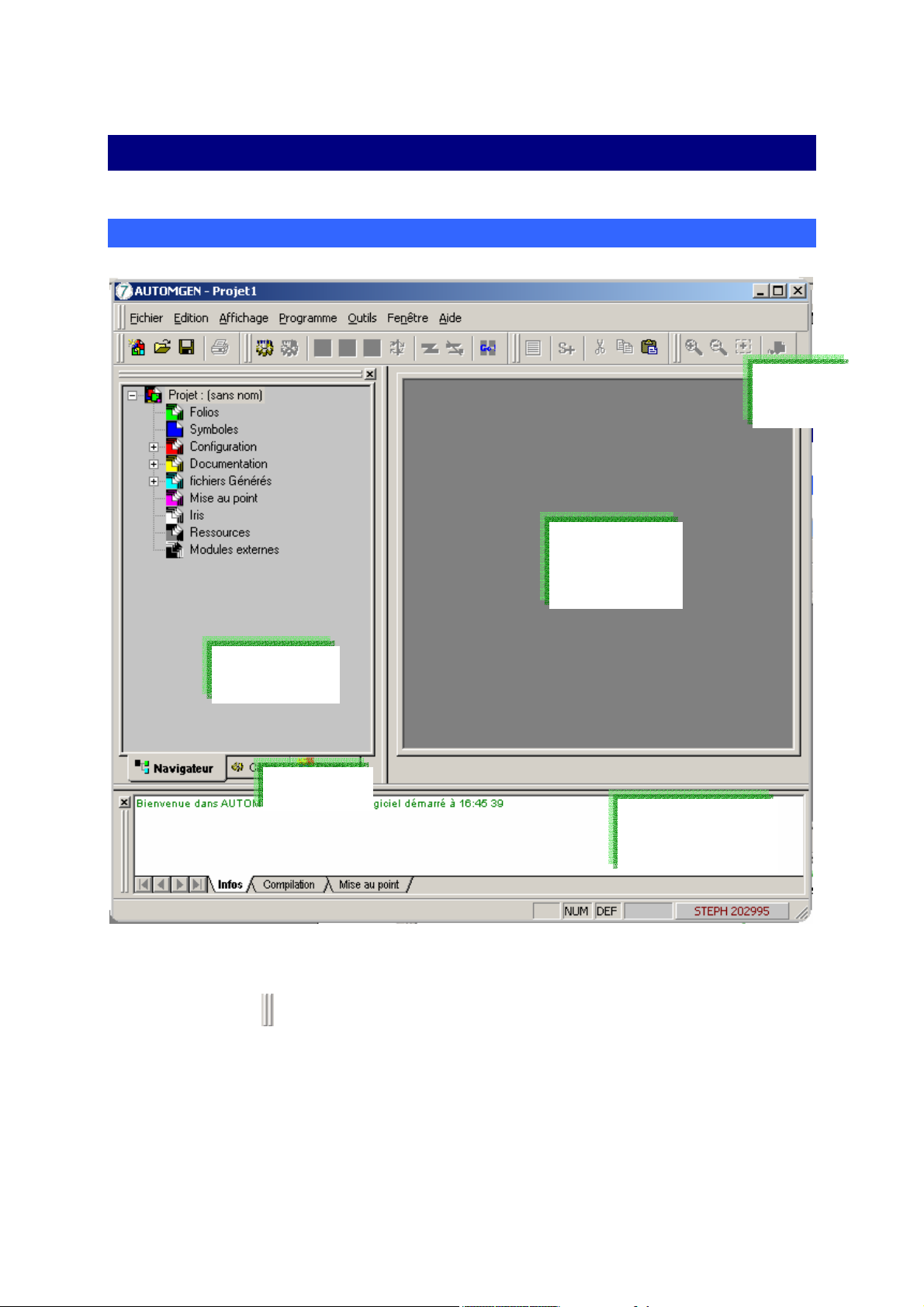
The environment
General overview
Toolbar
Work
space
Browser
Tab
Message
window
Main AUTOMGEN window
Parameters can be set for the entire environment. The toolbars can be
moved (using
environment » menu).
The environment state is saved when you close the program. This state
can also be saved in a project file (see project options).
AUTOMGEN7 10 (C)opyright 2002 IRAI
) and parameters set for them (« Tools/Customize
Page 11
Environment reference manual
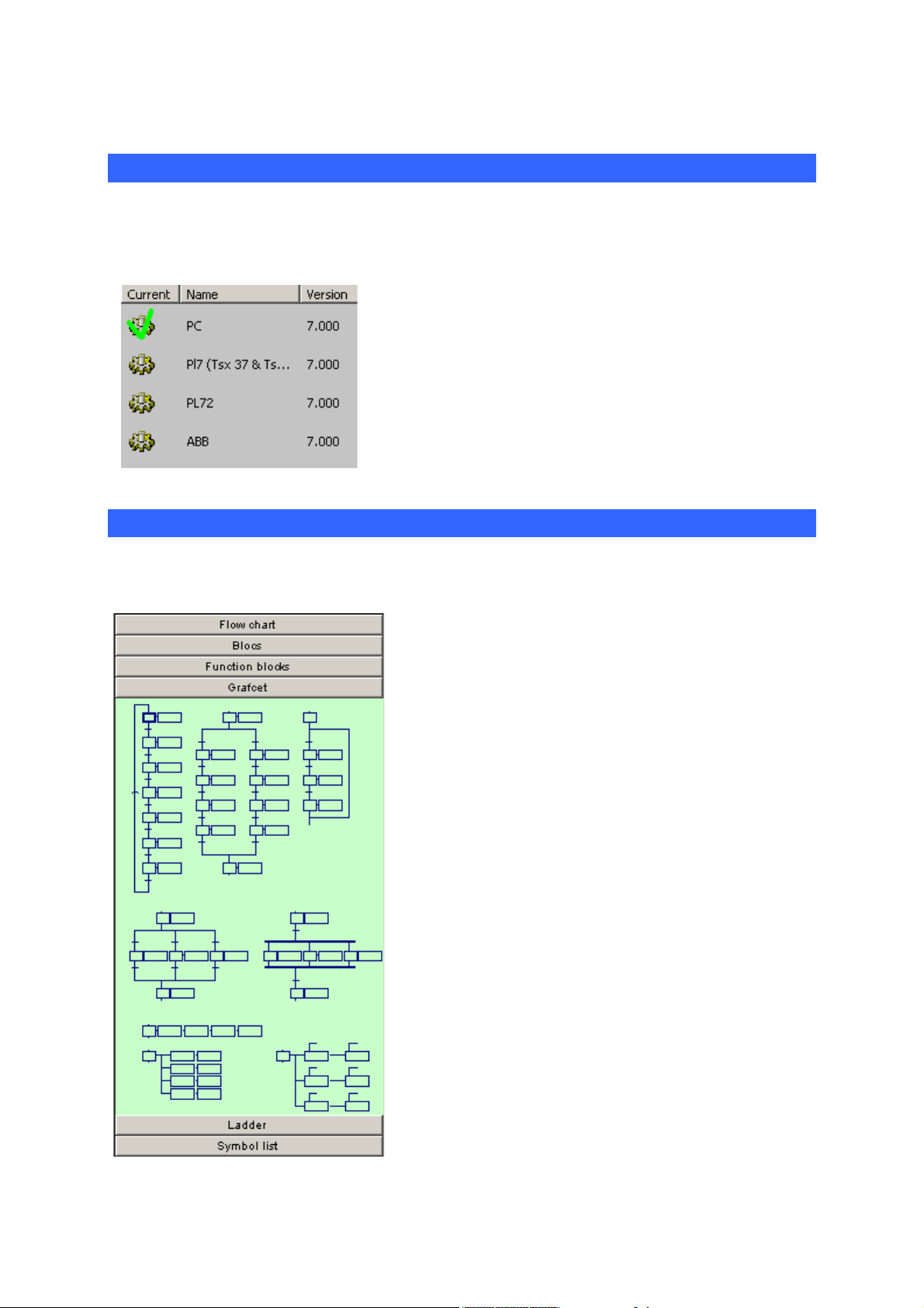
Selecting targets
The « Targets » tab is located at the bottom of the browser window, it
can be used to access the list of installed post-processors.
The active target is indicated by a green check
mark. Gray targets cannot be accessed due to the
installed license (see the « Licenses » chapter for
additional information). To modify the current target,
double click on the corresponding line.
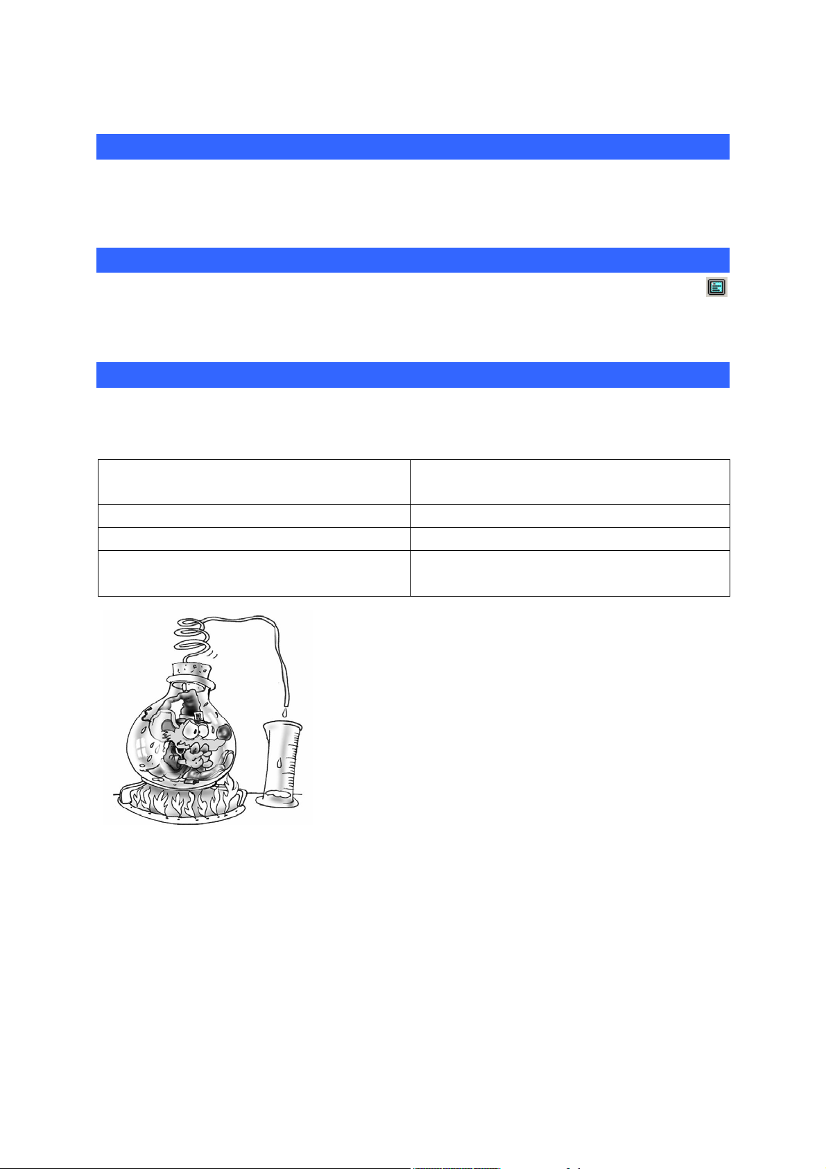
Palettes
The « Palette » is located at the bottom part of the browser window, it
can be used to access the program graphics elements.
The palette provides a group of elements which
can be selected and placed on sheets. To select
an element, click on the palette with the left side
of the mouse, drag the selection, release the
mouse, click in the selected area and move the
area to the sheet.
The palette also contains a list of project
symbols. You can drag and drop them on a text
or action on a sheet.
AUTOMGEN7 11 (C)opyright 2002 IRAI
Page 12
Environment reference manual
Displaying or hiding the project window or message window
Select the « Project » or « Messages » option from the « Window »
menu.
Displaying the work space in full screen mode
Select the « Full screen » option from the « Display » menu. Click on
to exit full screen mode.
Keyboard shortcuts
Keyboard shortcuts are written in the menus. « Masked » shortcuts can
also be used:
CTRL + ALT + F8 Save the project in executable
format
CTRL + ALT + F9 Save the project
CTRL + ALT + F10 Access project properties
CTRL + ALT + F11 Display or hide AUTOMGEN
window
Parameters can be set for the entire
environment, its state is saved when you
close AUTOMGEN. Environment windows
can be hidden. The « Windows » menu is
used to display them again. The work space
can be displayed in full screen mode. The
tabs at the bottom of the browser window are
used to access selection for the current postprocessor and the graphics palette.
AUTOMGEN7 12 (C)opyright 2002 IRAI
Page 13

Environment reference manual
Licenses
A license establishes AUTOMGEN user rights. The following elements
are established by license:
- the number of all or none inputs/outputs that can be used,
- post-processors that can be used,
- the number of users (only for network licenses).
Registering a license
When you install AUTOMGEN, you can use it for free for a period of 40
days.
You must register your license within 40 days.
To register your license, send IRAI:
- the serial number printed on the label glued to the software box, or
the reference of your delivery note or order form,
- the user code provided with the software indicating the PC where
you have installed the product.
You will then receive an enable code (also called validation code).
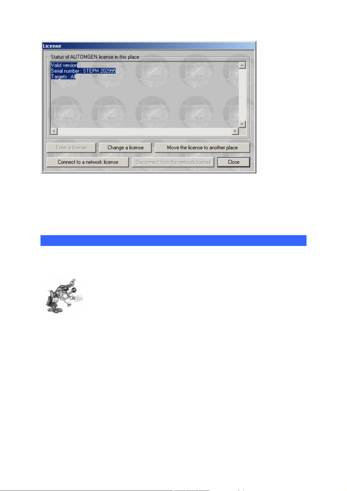
The « License » option in the AUTOMGEN « File » menu can be used to
display the status of your license and obtain a user code (click on
« Registering the license »).
AUTOMGEN7 13 (C)opyright 2002 IRAI
Page 14
Environment reference manual
License status.
A user code is valid for a period of 10 days.
So a maximum period of 10 days can pass from when you send a user
code to IRAI and when you receive an enable code provided by IRAI.
Sending a user code to IRAI
There are various methods you can use. Exchanging codes by e-mail is
highly recommended as it limits the risk of error.
A single error in the code will prevent the license from
being registered.
AUTOMGEN7 14 (C)opyright 2002 IRAI
Page 15
Environment reference manual
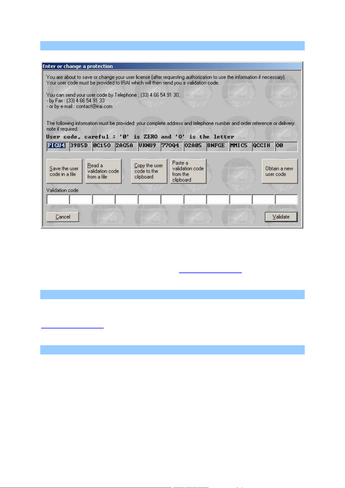
Sending a file by e-mail (the best solution)
License registration dialogue box
To generate a file containing your user code, click on « Save user code
in a file ». You can then transmit the file with « .a7u » extension as an
attachment and send it to the address contact@irai.com
.
Copying the user code in an e-mail message
By clicking on « Copy user code to clipboard », you can then paste the
code in the body of the message and transmit it to the e-mail address
contact@irai.com
.
By fax (not recommended)
By clicking on « Copy user code to clipboard », you can then paste the
code in a document and send it by fax to 33 4 66 54 91 33. If possible
avoid writing the code by hand and print it using a font which
differentiates between the letter « O » and the number zero.
AUTOMGEN7 15 (C)opyright 2002 IRAI
Page 16

Environment reference manual
By telephone (highly unadvisable)
By telephoning 33 4 66 54 91 30. Be sure to differentiate between the
letter « O » and number zero. Be careful of consonants which are difficult
to tell apart on the telephone (for example « S » and « F »).
Entering the validation/enable code
Validating by a e-mail received file
If you have received an « .a7v » file by e-mail, save the file on your hard
disk, click on « Read a validation code from a file » and select the file.
Validating for a code received in the text of an e-mail
Select the code in the message text (make sure you only select the code
and do not add any spaces to the end). Click on « Paste a validation
code from the clipboard ».
Validating for a code received by fax or telephone
Enter the code in the spaces under the title « Validation code ».
Modifying a license
Modification of a license Involves changing the elements authorized by
the license (for example adding a post-processor).
The license modification procedure is identical to registration.
Moving a license from one computer to another
This procedure is more complex. The instructions below must be
scrupulously followed to obtain good results. In the instructions below,
« source » PC indicates the computer with the license and the « target »
PC is the PC where the license needs to be moved.
1- if it has not already been done, install AUTOMGEN on the target
PC,
2- generate an « .a7u » user code file on the target PC and move this
file to the source PC (for example on a floppy disk),
3- on the source PC, select the « Move the license to another place »
option,
AUTOMGEN7 16 (C)opyright 2002 IRAI
Page 17
Environment reference manual
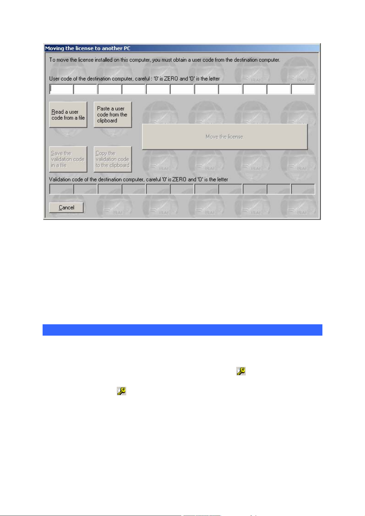
Dialogue box for moving a license
4- on the source PC, click on « Read a user code from a file » and
select the « .a7u » file that came from the target PC,
5- on the source PC, click on « Move the license »,
6- on the source PC, click on « Save the validation code in a file »,
recopy the generated « .a7v » file to the target PC,
7- on the target PC, click on « Read a user code from a file » and
select the « .a7v » file that came from the source PC.
Network licenses
The « akey7.exe » executable manages the network license. This
executable must be launched from one of the network computers. The
network must be able to be used with TCP IP protocol. When launched,
the network license manager is hidden and only a
WINDOWS keybar. To display the network license manager window,
double click on the
icon in the keybar.
icon appears in the
AUTOMGEN7 17 (C)opyright 2002 IRAI
Page 18
Environment reference manual
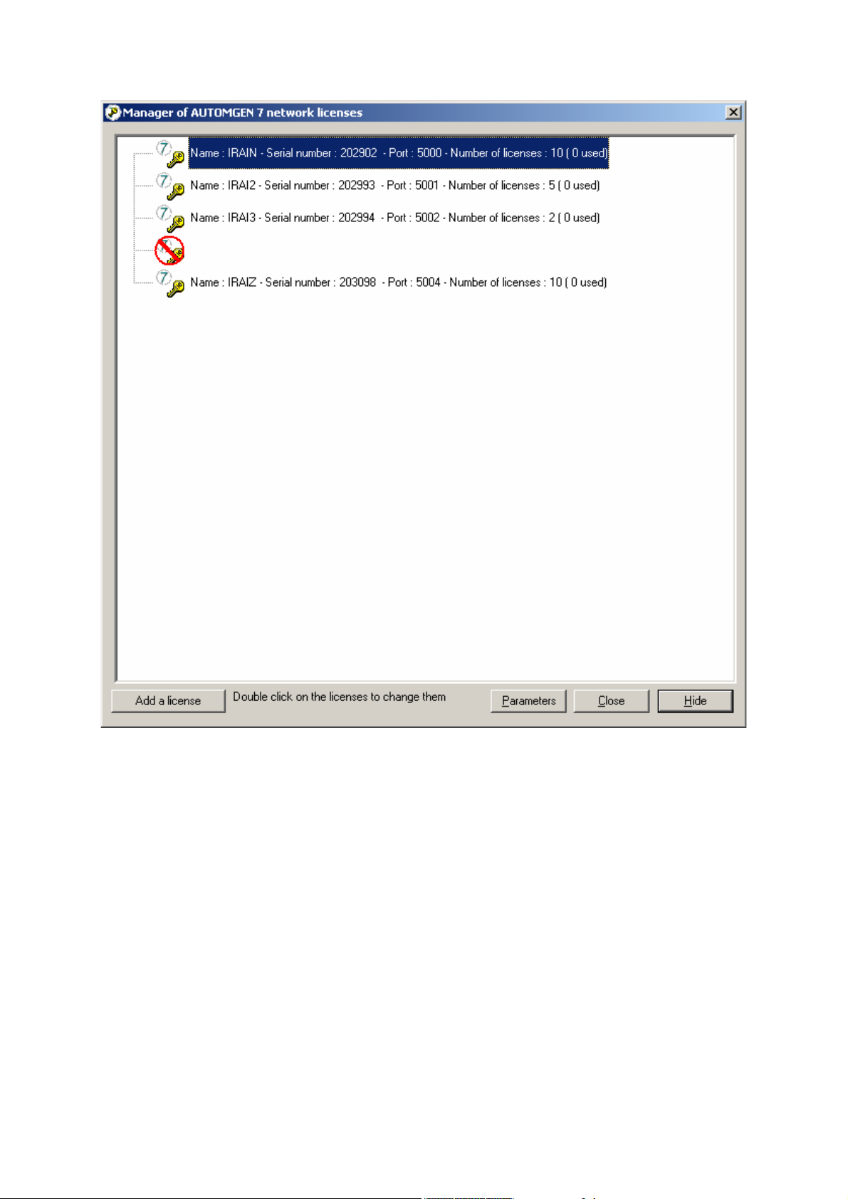
The network license manager
Up to 16 different licenses can be managed by the network license
manager. A network license is characterized by a number of users and a
type of copyright (number of all or none inputs/outputs and useable postprocessors). For each license the number of possible user/s, number of
connected user/s and list of connected users (using AUTOMGEN) is
displayed in a tree format attached to each license. Each license is
associated to a port number (a numeric value starting from 5000 by
default). The first port number used can be configured by clicking on
« Parameters ».
AUTOMGEN7 18 (C)opyright 2002 IRAI
Page 19
Environment reference manual
Adding a network license
You can add a license by clicking on « Add a license ». The license
registration principle is the same as for single license versions.
Modifying a license
Double click on the licenses to modify them. The license modification
procedure is the identical to that used for single license versions.
Connecting to client stations
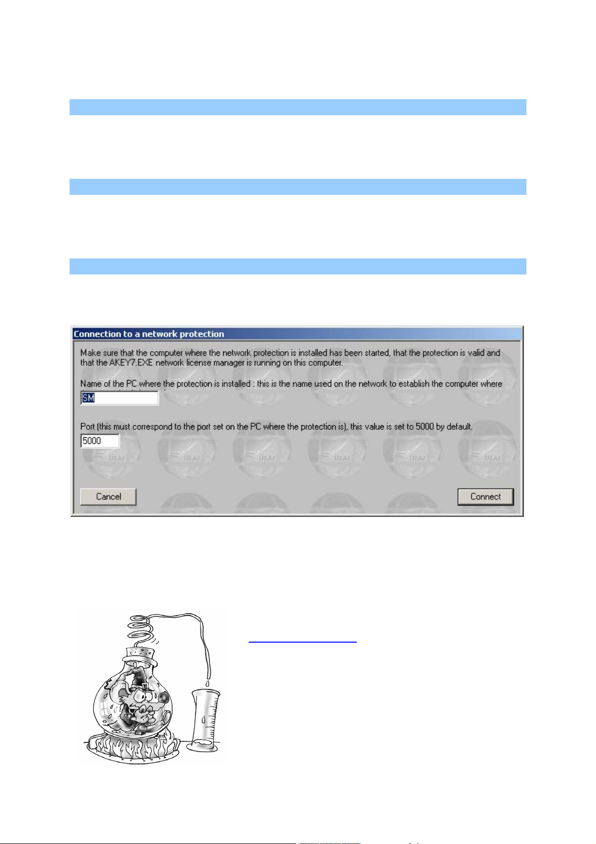
Click on « Connect to a network license » to connect a client station to a
network license.
Connecting to a network license
The PC name (the one from the network) where the « akey7.exe » was
launched must be provided as well as the port number corresponding to
the desired license.
You must register your license with IRAI
(contact@irai.com
) by sending your user
code by e-mail (« File/License » menu. The
network license manager is used to manage
multiple licenses on TCP IP network PC's.
AUTOMGEN7 19 (C)opyright 2002 IRAI
Page 20

Environment reference manual
The project
7
AUTOMGEN
is strongly based on the idea of a project. A project groups
together the elements that compose an application. The browser (see
page 23) displays all the project elements (sheets, symbols,
configuration, IRIS objects etc.) in a tree format.
The new file format of AUTOMGEN
7
(files with « .AGN » extension)
includes all project elements.
When you save an « .AGN » file you are assured of saving all the
elements of an application. You can easily and effectively interchange
applications created with AUTOMGEN.
« .AGN » files are compacted with « ZIP » technology, they do not need
to be compressed to be interchanged, their size is already optimized.
Importing an application from an older version of AUTOMGEN
You need to import all the sheets (« .GR7 » files) and symbol file
(« .SYM » file) if there is one. To do this use the importation procedures
described in the following chapters.
Importing a project created with another software workgroup
(available during the first six months of 2002)
The « Import » command from the « File » file menu is used to import
« .FEF » files from SCHNEIDER software workgroups.
Generating a free distribution executable file
The « Generate an executable » command from the « File » menu
is used to generate an executable starting from a project in
progress (an « .EXE » file executable on a PC with WINDOWS).
The AUTOMGEN « viewer » is automatically integrated with the
generated executable (the executable user does not need
AUTOMGEN). This viewer makes it possible to use the
application without modifying it. You can easily distribute your
applications. The generated executable is not covered by
copyright. This technique is normally used for producing a
supervising application.
AUTOMGEN7 20 (C)opyright 2002 IRAI
Page 21

Environment reference manual
Modifying project properties
With the right side of the mouse click on the « Project» element on the
browser and select « Properties » from the menu.
Modifying security options
You can restrict reading or modification access to a project by
passwords.
Advanced options
« Save the environment aspect with the project » : if checked, the
position of the windows and the aspect of the toolbars are saved in the
« .AGN » file. When the project is opened, these elements are
reproduced.
« Hide the main window upon launching … » : if checked, the
AUTOMGEN window is hidden when the project is opened. Only IRIS
objects incorporated in the project will be displayed. This option is
normally used to create « package » applications which only leave IRIS
objects displayed. Use the [CTRL] + [F11] keys to redisplay the
AUTOMGEN window.
The other options are used to change the display of the AUTOMGEN
window when a project is opened.
User interface
« Block IRIS object configuration » : if checked, a user cannot modify
IRIS object configuration.
The other options are used to modify the behavior of the user interface.
Model
« This project is a document model » : if checked, when opened all the
options and the documents it contains act as a model for the creation of
a new project. This functionality is used to create standard configuration
which can be uploaded when AUTOMGEN is launched (for example a
default symbol file or a default processor configuration).
Automatic GO
«Automatic go at project launch » : if checked, the application is
automatically run when a project is opened.
AUTOMGEN7 21 (C)opyright 2002 IRAI
Page 22

Environment reference manual
The project is used to group together the
elements of an AUTOMGEN application.
Once regrouped, the elements form a
compact file with « .AGN » extension. The
project models are used to be able to easily
manage different software configurations.
Generation of executables makes it easy to
distribute applications.
AUTOMGEN7 22 (C)opyright 2002 IRAI
Page 23
Environment reference manual
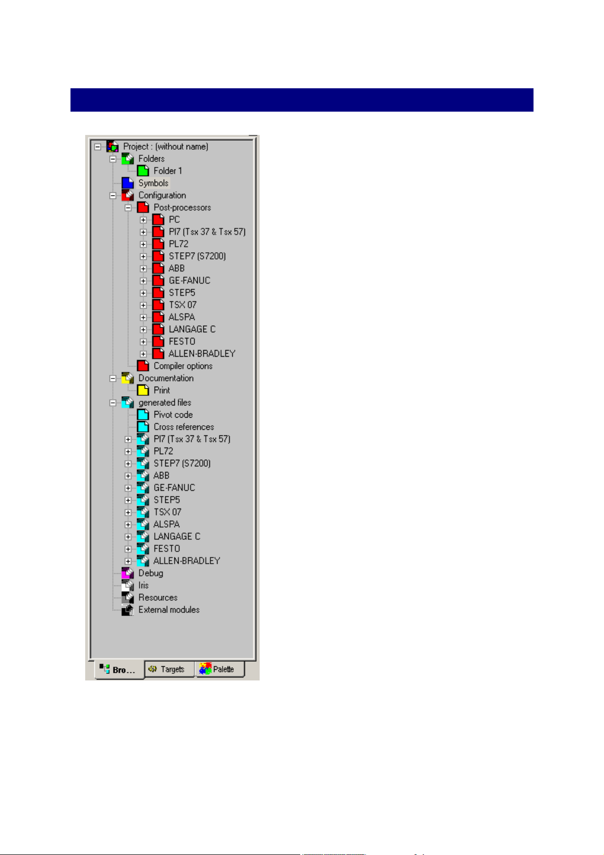
The Browser
A central element for application
management, the browser is used for
fast access to different application
elements : sheets, symbols,
configuration, printing, IRIS objects etc.
The « + » and « - » icons are used to
develop or retract project elements.
Actions on the browser are effected by
double clicking on the elements (opens
the element) or by clicking with the right
side of the mouse (adds a new element
to a project, special action on an
element etc.).
Certain operations are effected by
dragging and dropping the elements and
moving them on the browser.
The colors (generally called up at the
bottom of documents in the work space)
are used to identify families of elements.
Browser tree
AUTOMGEN7 23 (C)opyright 2002 IRAI
Page 24
Environment reference manual
Sheets
A sheet is a page where a program or part of a program is designed.
Using sheets is extremely simplified in AUTOMGEN
chaining orders needed in the previous versions are no longer used. For
multiple sheets to be compiled together, they only need to be in the
project.
The icons associated to the sheets are shown below:
-
-
-
-
-
-
normal sheet,
normal sheet (excluding compilation),
sheet containing a macro-step expansion,
sheet containing a function block program,
sheet containing a key,
sheet containing a key (excluding compilation).
Icons are marked with a cross indicating a closed sheet (not displayed in
the work space). Double clicking on this type of icon opens (displays) the
associated sheet.
7
. The sheet
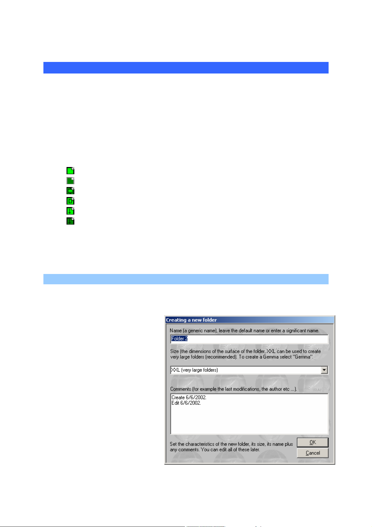
Adding a new sheet
With the right side of the mouse click on the « Sheets » element on the
browser then select « Add a new sheet ».
Select the sheet size (XXL is the
recommended format, the other
formats are for older versions of
AUTOMGEN, GEMMA is only
used for creating GEMMA
models).
The sheet can be given any
name, but each project sheet
must have its own name.
The comment area is up to your
discretion for modifications or
other information relative to each
sheet.
AUTOMGEN7 24 (C)opyright 2002 IRAI
Page 25
Environment reference manual
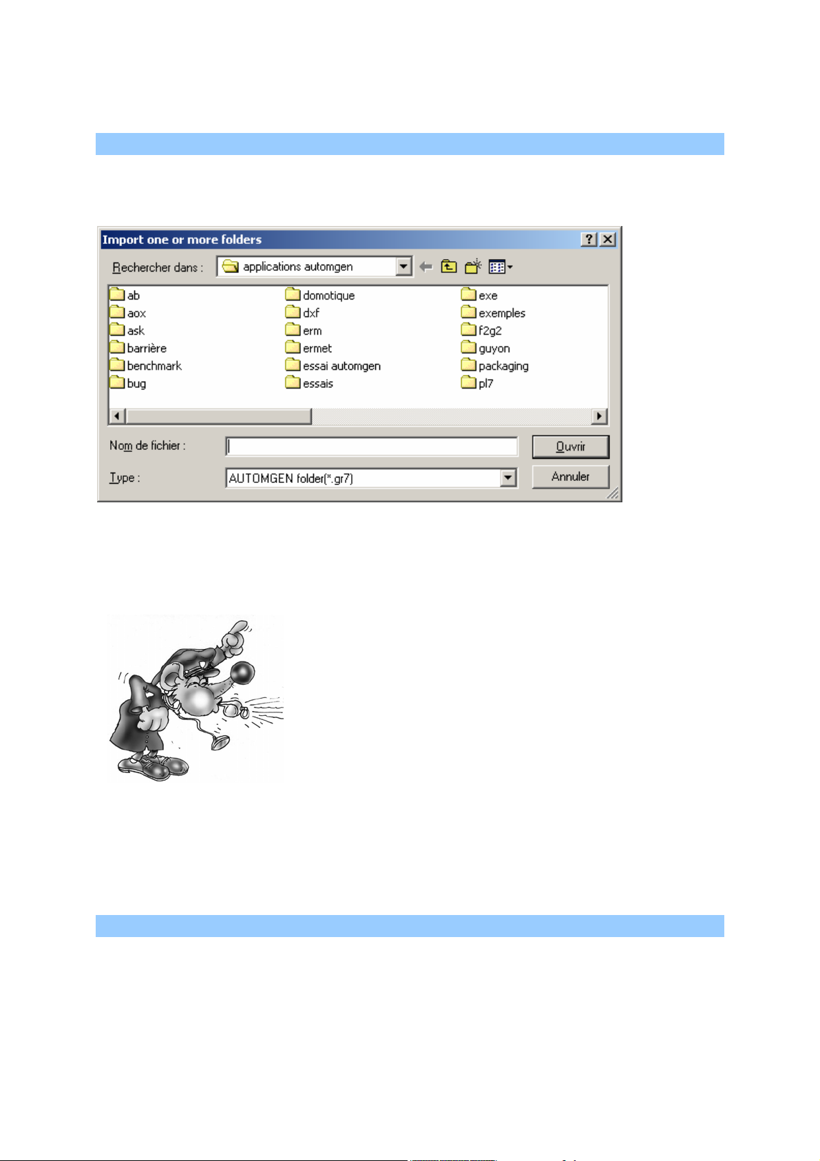
Importing old AUTOMGEN version sheets, importing CADEPA sheets
With the right side of the mouse click on the « Sheets » element on the
browser then select « Add one or more existing sheets ».
Selecting one or more sheets to import.
From the « Type » list select « AUTOMGEN » or « CADEPA » for the
sheet type to import then click on OK.
There are some restrictions for importing
CADEPA sheets:
- the step numbers must be individual (the
same step number cannot be used on
multiple sheets),
- references must be converted with links to
CADEPA before being able to import
them.
By keeping the [CTRL] key pressed down, you can select multiple
sheets.
Modifying the sheet compilation order
The sheets are compiled in the order they are listed in for the project. To
modify this order, click on the sheet with the left side of the mouse on the
browser and move it in the list.
AUTOMGEN7 25 (C)opyright 2002 IRAI
Page 26

Environment reference manual
Deleting a sheet from the list
With the right side of the mouse click the sheet to be deleted on the
browser and select « Delete » from the menu.
Exporting a sheet to a « .GR7 » file
With the right side of the mouse click the sheet to be deleted on the
browser and select « Export » from the menu.
Copying, Cutting, Pasting a sheet
With the right side of the mouse click the sheet on the browser and
select « Copy/cut » from the menu. To paste, with the right side of the
mouse click on the « Sheet » element on the browser and select
« Paste ».
This option makes it possible to copy or transfer sheets from one project
to another.
Renaming a sheet
See « Modifying properties » below.
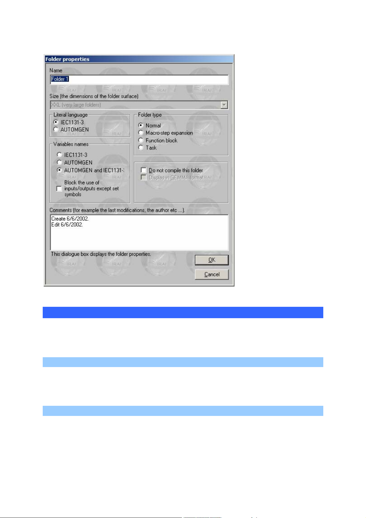
Modifying sheet properties.
With the right side of the mouse click the sheet on the browser and
select « Properties » from the menu.
AUTOMGEN7 26 (C)opyright 2002 IRAI
Page 27
Environment reference manual
You can modify the
sheet name, the syntax
used for literal
language and variable
names. The « Do not
compile this sheet »
option is used to
exclude the sheet from
the compilation. The
« Display in GEMMA
format» option is only
available if the sheet
format is GEMMA and
is used to display and
modify a sheet in
GEMMA format. The
« Block the of use
inputs/outputs other
than set symbols »
option blocks the use of
i, %i, o %q variables
not attributed to
symbols. The
« comments » area is
left to your discretion.
Symbols
The list of symbols provides the correspondence between « symbol »
names and variable names. A project may only have one symbol table.
Creating a symbol table
With the right side of the mouse click on the « Symbols» element on the
browser and select « Create a symbol table » from the menu.
Importing a symbol table
With the right side of the mouse click on the « Symbols» element on the
browser and select « Import a symbol table » from the menu.
AUTOMGEN7 27 (C)opyright 2002 IRAI
Page 28

Environment reference manual
Configuration
Post-processors
This section contains all the post-processor configuration elements (see
the post-processor manual for more information).
Compiler options
Double click on this element to modify the settings of compiler options.
Documentation
This is used to access the file printing function (double click on the
« Print » element. You can print a complete file composed of an end
paper, cross reference table, symbol list and sheets. The print setup
function is used to display all these elements.
AUTOMGEN7 28 (C)opyright 2002 IRAI
Page 29
Environment reference manual
Generated files
Generating the instruction list in pivot code
By double clicking on « Pivot code » you generate a list in low level literal
language (AUTOMGEN pivot code). Viewing of the generated code is
normally reserved for specialists involved in understanding the
translation methods used by the compiler.
Generating the cross reference list
Double clicking on the « Cross reference » element generates and
displays the list of variables used in an application with any associated
processor variables and the name of or sheet(s) where they are used.
Post-processors
The other elements concern the files generated by the post-processors:
instruction lists are in processor language.
Settings
Contains the tools to display and modify the state of the variables.
Viewing and modifying a variable or variable table
With the right side of the mouse click on « Settings » and select
« Monitoring » to open an element where you can see the state of a
variable or variable table.
A monitoring window.
Next variable
Previous
variable
Select a
variable
Modify the state
of another
variable
Close
Open the
menu
AUTOMGEN7 29 (C)opyright 2002 IRAI
Page 30
Environment reference manual
Modify the
variable state by
clicking in this
area
The monitoring window in « Variable table » mode.
IRIS objects
IRIS 2D objects are used to create consoles, supervision applications
and simulation applications of 2D operating parts. IRIS 3D is used to
create simulation applications of 3D operating parts. Each IRIS 2D object
appears in the project tree (see the chapters IRIS 2D references and
IRIS 3D references for additional information).
Adding an IRIS 2D object
Click with the right side of the mouse on « Add an IRIS 2D object ». The
object selection assistant is used to select it and set its parameters.
AUTOMGEN7 30 (C)opyright 2002 IRAI
Page 31

Environment reference manual
Selection assistant for an IRIS 2D object
Deleting an IRIS 2D object
With the right side of the mouse click on the IRIS object on the browser
and select « Delete » from the menu.
Displaying or hiding an IRIS 2D object
With the right side of the mouse click on the IRIS object on the browser
and select « Display/hide » from the menu.
AUTOMGEN7 31 (C)opyright 2002 IRAI
Page 32

Environment reference manual
Cutting, copying, pasting an IRIS 2D object
With the right side of the mouse click on the IRIS object on the browser
and select « Copy » or « Cut » from the menu.
To paste, with the right side of the mouse click on the « Sheet » element
on the browser and select « Paste ».
To paste an IRIS object on a console, select « Paste» from the console
menu or click with the right side of the mouse on the console on the
browser and select « Paste».
Adding a new IRIS 2D object on a console
Select « Add an object » from the console menu or click with the right
side of the mouse on the console on the browser and select « Add an
object on the console » from the menu (for more information on the
console see the chapter « Console » object)
Modifying the properties of an IRIS 2D object
With the right side of the mouse click on the IRIS object on the browser
and select « Properties ». For higher level objects (parent objects),
special properties can be accessed:
Properties of high level objects
Display establishes under which conditions the object is displayed or
hidden. The reinstallation option is used to return an object to its initial
state when dynamic display is launched (normally used for OP simulation
applications).
AUTOMGEN7 32 (C)opyright 2002 IRAI
Page 33

Environment reference manual
Setting an object model accessible on the assistant
With the right side of the mouse click on the IRIS object on the browser
and select « Save as model » from the menu.
Selection of modifiable parameters for users of your models
You can select the list of parameters which remain accessible to the user
on the assistant. By clicking on « Save », you save your object model.
The storage directory for object models is « <AUTOMGEN installation
directory>\i2d\lib ». You can use a sub-directory called « my objects » for
saving your models.
Importing an IRIS 2D object in an earlier version of AUTOMGEN
With the right side of the mouse click on the « IRIS» element on the
browser and select « Import IRIS 2D objects ». Select one or more
« .AOF » files.
AUTOMGEN7 33 (C)opyright 2002 IRAI
Page 34

Environment reference manual
Creating an IRIS 3D console
With the right side of the mouse click on the « IRIS » element on the
browser and select « Add an IRIS 3D console » (see the chapter on IRIS
3D for more information).
Resources
This project element is used for adding all types of files to a project. Files
which are added will become an integral part of the project and will be
saved along with the other elements. To refer to a pseudo directory
where the resources are, the key word « <RESDIR> » can be used in the
specific directory name in AUTOMGEN. For example IRIS objects can
refer to bitmaps if they are included in the resources.
Adding a file to the resources
With the right side of the mouse click on the « Resources» element on
the browser and select « Add » from the menu.
Deleting a file from the resources
With the right side of the mouse click the resource file on the browser
and select « Delete ».
Renaming a file in the resources
With the right side of the mouse click the resource file on the browser
and select « Rename ».
Modifying a file in the resources
With the right side of the mouse click the resource file on the browser
and select « Modify ».
Adding and converting 3D STUDIO files in the resources
3D STUDIO files can be converted into .x files and added to the
resources by clicking with the right side of the mouse on the
« Resources » element on the browser and selecting « Import 3D files »
(see the chapter IRIS 2D references and IRIS 3D references for more
information).
External modules
These elements are reserved for executable modules developed by third
parties and interfaced with AUTOMGEN.
AUTOMGEN7 34 (C)opyright 2002 IRAI
Page 35

Environment reference manual
The browser is used to display and manage
all the project elements. By double clicking
on the elements or by clicking with the right
side of the mouse, you access the different
functions applicable to each element.
AUTOMGEN7 35 (C)opyright 2002 IRAI
Page 36

Environment reference manual
Designing programs
Various tools are available for designing programs.
Designing with the assistant
This is without doubt the simplest when starting with AUTOMGEN. With
the right side of the mouse click on an open sheet in the work space and
select « Assistant » from the menu. You will then be guided for making
selections. When you have finished click on « OK » and put the design
on the sheet by clicking with the left side of the mouse.
The assistant
AUTOMGEN7 36 (C)opyright 2002 IRAI
Page 37

Environment reference manual
Designing with the shortcut menu
Click with the right side of the mouse on an open sheet in the work
space, the menu will propose a series of elements that you can put on
the sheet. This is an instinctive and fast creation method.
Designing with the pallet
By selecting elements on the pallet you can quickly create programs
starting from previously created elements.
Enhancing and customizing the pallet
« .GR7 » files are used to set the pallet, they are located in the directory
« <AUTOMGEN installation directory>\pal ». You can delete, modify,
rename or add files. To generate « .GR7 », files use the « Export »
command by clicking with the right side of the mouse on a sheet on the
browser. The names displayed on the pallet are « .GR7 » files. Relaunch
AUTOMGEN for a new element to be displayed on the pallet.
Designing with the keyboard keys
Each key is associated to design blocks. The « Blocks » element also
provides access to the blocks. The table below lists the blocks and their
use.
Delete block
Aspect Associated key Generic name Comments Languages
[A] Delete
Link blocks
Aspect Associated key Generic name Comments Languages
[E] Vertical link
Used to make a cell blank
again
Link from top to bottom
or bottom to top
All
All
AUTOMGEN7 37 (C)opyright 2002 IRAI
[F] Horizontal link
Link from right to left or
left to right
All
Page 38

Environment reference manual
[G] Upper left corner
[H] Upper right corner
[I] Lower left corner
[J] Lower right corner
[Z] Cross Crosses two links All
Link towards the bottom
right or bottom left
Link towards the bottom
left or bottom right
Link from top to right or
left to top
Link from top to left or
right to top
All
All
All
All
Grafcet blocks
Aspect Associated key Generic name Comments Languages
[B] Step Normal step Grafcet
[C]
[D] Initial step Initial step Grafcet
Macro-step
[T] Transition Transition Grafcet
[K]
[L]
Initial step without
activation
Left limit of an « And »
divergence
Supplementary branch
of an « And »
divergence or an
« And » convergence
Initial step without
activation
Only available in the
shortcut menu
Compulsory to the left
of an « And »
divergences
Do not use as a left or
right limit of an « And »
divergence
Grafcet
Grafcet
Grafcet
Grafcet
AUTOMGEN7 38 (C)opyright 2002 IRAI
Page 39

Environment reference manual
[M]
[N]
[O]
[P]
[Q]
Right limit of an
« And » divergence
Extension of an « And »
divergence
Left limit of an « And »
convergence
Supplementary branch
of an « And »
convergence or an
« And » divergence
Right limit of an
« And » convergence
Compulsory to the right
of an « And »
divergence
If placed in the [K], [L],
[M], [P] or [O],[P],[Q],
[L] blocks
Compulsory to the left
of an « And »
convergence
Do not use as a left or
right limit of an « And »
convergence
Compulsory to the right
of an « And »
convergence
Grafcet
Grafcet
Grafcet
Grafcet
Grafcet
[R] « Or » divergence
[S] « Or » convergence
[U] Skip or repeat left step
[V] Skip or repeat right step
[SPACE] on an
[E] block
Flowchart blocks
Aspect
Associated
key
[0] (zero) Flowchart assignment
Do not use as a limit of
an « Or » convergence
Do not use as a limit of
an « Or » divergence
« Or » convergence or
divergence
« Or » convergence or
divergence
Link towards the top
Generic name Comments Languages
For relooping and
repeating steps
Separates the « test »
from the « action »
area
Grafcet
Grafcet
Grafcet
Grafcet
Grafcet
Flowchart
AUTOMGEN7 39 (C)opyright 2002 IRAI
Page 40

Environment reference manual
[1] « Not » function
[2] « And » function
[3] « Or » function
[4] Block environment
[5] Bottom of block
Complements the
block input signal
Combines the inputs in
an « And » logic
Combines the inputs in
an « Or » logic
Enlarges an « And » or
« Or » function block
Ends an « And » or
« Or » function block
Flowchart
Flowchart
Flowchart
Flowchart
Flowchart
Ladder blocks
Aspect Associated key Generic name Comments Languages
[(] Start left coil Starts an action Ladder
[)] Start right coil Ends an action Ladder
[U] Left limit Ends the diagram Ladder
[V] Right limit Starts the diagram Ladder
[R] Connection « Or » function Ladder
[S] Connection « Or » function Ladder
Action blocks
Aspect
Associated
[W]
key
Generic name Comments Languages
Action rectangle left
limit
Starts an action Grafcet and Flowchart
AUTOMGEN7 40 (C)opyright 2002 IRAI
Page 41

Environment reference manual
Test blocks
Aspect
Associated
[X]
[Y]
[S] Divergence Action
[V] Divergence Action
key
[7] Left limit of a test Starts a test Flowchart and ladder
Action rectangle
environment
Action rectangle
right limit
Generic name Comments Languages
Extends an action Grafcet and Flowchart
Ends an action Grafcet and Flowchart
Used to vertically
juxtapose action
rectangles
Used to vertically
juxtapose action
rectangles
Grafcet and Flowchart
Grafcet and Flowchart
[6] Right limit of a test Ends a test Flowchart and ladder
Organization chart blocks
Aspect
Associated
Generic name Comments Languages
key
[<]
[=] « False » output
Organization chart
input
Indicates the input in a
rectangle
Output if a test
rectangle is false
Organization
chart
Organization
chart
AUTOMGEN7 41 (C)opyright 2002 IRAI
Page 42

Environment reference manual
Function block blocks
Aspect
Associated
key
[8]
[9]
[:]
[;]
[>]
[?]
Generic name Comments Languages
Upper left corner of a
function block
Upper right corner of a
function block
Lower left corner of a
function block
Left limit of a function
block
Right limit of a
function block
Lower right corner of a
function block
Starts the name of the
function block
Ends the name of the
function block
Adds an input to the
function block
Adds an input to the
function block
Adds an output to the
function block
Adds an output to the
function block
Function block
Function block
Function block
Function block
Function block
Function block
Documenting program elements
To document program elements, click below with the left side of the
mouse. To create comments, click on a blank space on the sheet. To
validate modifications, push the [Enter] key or click outside the editing
are with the left side of the mouse. To delete modifications, push the
[Esc] key or click outside the editing area with the right side of the
mouse.
When editing tests and actions, a « … » button appears under the editing
area. If you click on it you access an assistant for creating tests or
actions.
AUTOMGEN7 42 (C)opyright 2002 IRAI
Page 43

Environment reference manual
Test creation assistant
Adding symbols
To create a symbol, click with the right side of the mouse on the symbol
table in the work space and select « Add ». Or click the
toolbar. You can also launch program compiling containing unset
symbols. You will be asked for variables corresponding to the symbols
during the compilation.
button on the
AUTOMGEN7 43 (C)opyright 2002 IRAI
Page 44

Environment reference manual
Attribution of symbols during compilation
To easily design a program, create a new
sheet, then click with the right side of the
mouse on the bottom of the sheet. Select
« Assistant » from the menu, you will then
be guided by it.
AUTOMGEN7 44 (C)opyright 2002 IRAI
Page 45

Environment reference manual
Running an application
To run an application easily
The
results. This pushbutton activates the following mechanisms:
To end the run
Click on
on the target. On the PC, the program is stopped.
To compile only
Click on
To stop the compilation
button on the toolbar is the quickest way to see application run
- compilation of the application if it is not updated (not already
compiled after the last modifications),
- installation of the run module (with downloading if the current target
is a processor and following the connection options),
- passage of the target to RUN,
- activation of the dynamic display.
. On the processor target, the program continues to be run
.
Click on
To connect to a processor or install a PC
Click on
To disconnect a processor or uninstall a PC
Click on
To put the target in RUN mode
Click on
To put the target in STOP mode
Click on
To initialize the target
Click on
.
.
.
.
.
.
AUTOMGEN7 45 (C)opyright 2002 IRAI
Page 46

Environment reference manual
To run a program cycle on the target (generally not supported on processors)
Click on
.
To activate the dynamic display
Click on
.
To run an application, click on the « GO »
button. To end the run, click again on the
same button.
AUTOMGEN7 46 (C)opyright 2002 IRAI
Page 47

Environment reference manual
The compiler
The compiler translates the sheets into a set of pivot language equations
(these can be displayed by double clicking on the « Generated code /
pivot language » element on the browser).
The pivot language is then translated into a language which can be run
by a post-processor (the current post-processor can be displayed and
selected by double clicking on the « Targets » panel accessible by
clicking on the « Targets » tab at the lower part of the window where the
browser is.
Modifying compiler options
Double click on the element « Configuration / Compiler options».
Displaying compilation messages
The « Compilation » panel on the messages window contains the counts
produced by the last compilation.
Finding an error
By double clicking on error messages, you can find the source.
An error message and its source
AUTOMGEN7 47 (C)opyright 2002 IRAI
Page 48

Environment reference manual
If the message windows are hidden and if one or more errors are
detected by the compiler, a dialogue box indicates the first error detected
(to display the message windows : use the « Messages » command from
the « Windows » menu).
At the end of the compilation the
« Compilation » window provides a list of
any errors. By double clicking on the error
messages, the site in the program that
caused the error is displayed.
AUTOMGEN7 48 (C)opyright 2002 IRAI
Page 49

Environment reference manual
Running programs on a PC
The « run PC» target is an actual processor loaded in your PC.
You can:
- test your applications,
- drive a virtual operating part created with IRIS 2D or 3D,
- drive input/output cards connected to the PC.
Configuring the number of variables
Double click on the « Configuration / Post-processors / Executor PC /
Variables » element.
Selecting the number of variables
The space needed for the variables used in the application is
automatically reserved by default. You can manually select the amount
of memory to reserve for each type of variable. This may be necessary if
an indexed addressing is used to access a variable table.
AUTOMGEN7 49 (C)opyright 2002 IRAI
Page 50

Environment reference manual
PC system variables
Bits 0 to 99 and words 0 to 199 are system variables and can not be
used as user variables in your applications. The two tables below provide
details on the PC system variables.
Bits Use
0
1 to 4
5 to 7
8
9 and
10
11
12
13 to
29
30
31
32
33
34
35
36
37
38 to
55
56
57 to
67
68 to
99
active at first cycle, activation of initial Grafcet steps
reserved for I/O drivers
reserved for I/O driver errors
error on watchdog overflow is equal to 1
error general PC fault
run mode 1=RUN, 0=STOP
emergency stop pass to 1 in the event of an error or set to 1 to stop the program
reserved for drivers
bit associated to timer 1
bit associated to timer 2
bit associated to timer 3
bit associated to timer 4
bit associated to timer 5
bit for repeating sector (pass to 1 on repeat sector, reset to zero is the job of the
programmer)
setting this bit to 1 causes reading of the clock in real time and transfer to System
words 4, 5, 6, 7, 8, 51 and 52.
setting this bit to 1 causes writing of System words 4, 5, 6, 7, 8, 51 and 52 in the
real time clock.
reserved
division by zero
reserved for future versions
reserved for the stack of boolean processing
Words Use
0
1 to 3
4
5
6
7
8
9 to 29
30
AUTOMGEN7 50 (C)opyright 2002 IRAI
reserved for the upper part of the multiplication result or the remainder of the
division
timers in milliseconds
timer in 1/10 second
timer in seconds
timer in minutes
timer in hours
timer in days
reserved for I/O drivers
timer 1 counter
Page 51

Environment reference manual
31
32
33
34
35
36
37
38
39
40
41
42 to
50
51
52
timer 2 counter
timer 3 counter
timer 4 counter
timer 5 counter
timer 1 procedure
timer 2 procedure
timer 3 procedure
timer 4 procedure
timer 5 procedure
lower part of clock reference
upper part of clock reference
reserved for I/O drivers
timer in months
timer in years
Modifying the run period
Double click on « Post-processors / Executor PC / Run ».
Setting the run period
Driving inputs/outputs
Double click on « Configuration / Post-processor / Executor PC / I/O
Drivers ».
AUTOMGEN7 51 (C)opyright 2002 IRAI
Page 52

Environment reference manual
Adding an I/O driver
Select a driver from the list on the right and then click on « Add ».
« Set parameters » is used to configure certain drivers.
The executor PC transforms your PC into a
program processor, it can be used to drive
inputs/outputs directly connected to your
computer.
AUTOMGEN7 52 (C)opyright 2002 IRAI
Page 53

Environment reference manual
IRIS 2D references
IRIS 2D objects are used to create supervision and simulation
applications of 2D operating parts.
The link between the objects and the automatically functioning
applications is always created by interchanging the variable state.
IRIS 2D objects are contained in WINDOWS windows.
An IRIS 2D object
IRIS 2D objects have two possible states: the « Configuration » mode
(used to modify the object characteristics) and « Use » mode (for using
an object). The « User » mode is also called « Employ » mode.
Modifying object display
The objects can be hidden or displayed. This property can be specified
when opening an object or when changing the state of the dynamic
display in the environment. Only higher level objects (not objects located
on a console) can be displayed or hidden. Objects located on a console
are displayed or hidden at the same time as the console.
To dynamically modify the visibility of objects, click with the left side of
the mouse on the objects on the browser and select « Display/Hide ».
To modify the display properties, click with the left side of the mouse on
the objects on the browser and select « Properties ».
AUTOMGEN7 53 (C)opyright 2002 IRAI
Page 54

Environment reference manual
Display properties of an object.
Modifying object characteristics
Removing an object
Method 1: click the
button on the surface of the object.
Method 2: with the right side of the mouse click on the object on the
browser and select « Delete » from the menu.
Dimensioning an object
By dragging the object from one of its edges you can enlarge or shrink it
(you can also precisely modify the size of an object by accessing its
properties, see below).
Moving an object
Drag the object by clicking with the left side of the mouse on the minibar
located on the upper part of its surface.
Putting an object in « User » mode
Method 1: click on the button
on the object with the left side of the
mouse.
Method 2: click with the right side of the mouse on the object.
Putting an object in « Configuration » mode
Click with the right side of the mouse on the object.
Modifying the characteristics of an object
Method 1: click on the
button.
Method 2: push down the [CTRL] key on the keyboard and click with the
right side of the mouse on the object, then release the [CTRL] key.
AUTOMGEN7 54 (C)opyright 2002 IRAI
Page 55

Environment reference manual
Method 3: with the right side of the mouse click on the object on the
browser and select « Properties » from the menu.
Block access to configuration for all objects
With the right side of the mouse click on « Project » on the browser,
select « Properties » and check « Block IRIS 2D object configuration »
on the « Advanced » tab.
Basic objects, preset objects
The basic objects set major functionality types. Preset objects are based
on a basic type and a configuration to meet a specific need. For an
example, an emergency pushbutton is an object derived from a basic
object used to create pushbuttons and lights. To access preset objects,
use the assistant by clicking with the right side of the mouse on the
« IRIS » element on the browser and select « Adding an IRIS 2D
object ».
List of basic objects
« Console » object
The console object is the only object which can contain other objects on
its surface. It is used to create command consoles and animation
surfaces for virtual operating parts. This object has a pushbutton
to manage objects on its surface: add, move, delete etc.
The « Button and light » object
This is used to create pushbuttons and lights that interact with the
processing application variables.
The« Object » object
This is a polymorphic element primarily used to simulate operating parts.
The « Digital value » object
This is used to display numeric values of the processing application in a
number format.
used
The « Screen, keyboard, message list » object
This is used to display information on the processing application in a text
format.
AUTOMGEN7 55 (C)opyright 2002 IRAI
Page 56

Environment reference manual
The « Sound » object
This is used to produce output sounds when the variable state of the
processing application changes.
The « Data archive » object
This is used to display processing application data in a table or chart
format and save them in the computer memory or on the disk.
The « Program » object
This is used for processing run separately from the processing
application.
The « Dialogue box » object
This is used to display messages in a pop-up window format regarding
changes in the variable state of the processing application.
The « Analog value » object
This is used to display processing application numeric variables in an
analog numeric format (bars, dials etc.).
Practical experience
In this chapter you will be able to quickly create your first IRIS 2D
application. We are going to create a console, put a pushbutton on it and
link the object variables to the processing application.
Step 1
Creating a minimal application with AUTOMGEN see chapter Designing
programs.
This is a Grafcet with one step as shown below.
0
AUTOMGEN7 56 (C)opyright 2002 IRAI
Page 57

Environment reference manual
Step 2
Launch the run of the AUTOMGEN application (click on the « Go »
button on the toolbar).
Step 3
With the right side of the mouse click on the « IRIS » element on the
browser and then select « Add an IRIS 2D object » from the menu. In the
« Basic objects » category, double click on « Console ».
At this point the object will appear on the screen in this format:
Step 4
To add a pushbutton to the console click on the console icon
(menu
access) and select the « Add an object » option. In the « Basic objects »
category, double click on « illuminated button ».
The object will then appear on the console:
Step 5
Now we are going to associate the pushbutton to a processing
application output, for example %Q4. Click the pushbutton icon
(not
the console icon). The pushbutton properties dialogue box will open:
AUTOMGEN7 57 (C)opyright 2002 IRAI
Page 58

Environment reference manual
Click the « Links » tab (upper part of the dialogue window). In the
« Action when button is pressed » section enter « %Q4=1 ». In the
« Action when button is released » section enter « %Q4=0 ». Then click
on « OK » on the pushbutton on the lower part of the dialogue window.
Actions on the pushbutton will drive processing application output 4. You
can open a « Monitoring » window from the « Set-up » menu by clicking
with the right side of the mouse on the browser. You display the state of
output 4 when you click then release the pushbutton.
Step 6
We are going to associate a light to the « Illuminated Button » object, this
light will be associated to a processing application input (for example 12).
Click the pushbutton icon
again. In the « Aspect » tab click on the
« Pushbutton and light » radio button. Click on the « Links » tab and
enter « %i2 » in the « Light state » section. Click on the « OK »
pushbutton in the lower part of the property dialogue window. You can
keep the state of variable « %i2 » modified (with a « Monitoring » window
or by modifying the state of the physical input, if it exists).
AUTOMGEN7 58 (C)opyright 2002 IRAI
Page 59

Environment reference manual
Step 7
We are going to duplicate the « Illuminated Button » on the console in
order to obtain a second pushbutton whose properties we will modify.
Click on the pushbutton with the left side of the mouse while pressing
down the [SHIFT] key. Black squares will appear around the selected
object. Click on the console icon
Click on the console icon
and select the « Paste » option. Now there
and select the « Copy » option.
are two overlapping « Illuminated Button» objects. Drag the upper one (it
is the only accessible one) by its upper bar and move it away from the
other pushbutton. The object which has been duplicated has the same
properties as the first. Now you can set the parameters for the second
object, for example, so it is linked to output 5 and input 3.
You can also customize the aspect of the pushbuttons by using the
aspect tab for the two objects. You can modify the size of the objects by
dragging their edges.
The three objects on the screen (console and two pushbuttons) are in
« Configuration » mode, this means that they have a mini bar on the
upper part of their surface, icons and edges for modifying their
dimensions. The objects have another mode called « Employ », in this
mode their aspect is permanent: the upper bar, icon and edges for
modifying the dimensions no longer exist. To tilt an object, click on it with
the right side of the mouse.
At this point you will have created an object that looks like this:
AUTOMGEN7 59 (C)opyright 2002 IRAI
Page 60

Environment reference manual
Creating an autonomous supervision application
To create an autonomous supervision application (without developing a
processing application with AUTOMGEN) follow the procedure below:
- create correspondences for the AUTOMGEN variables and the
processor variables by double clicking on the « Configuration /
Post-processor / <post-processor name> / Variable
correspondence » element (see the post-processor manual for
more information).
- compile the application by clicking on the
(this validates the variable correspondence).
- configure the connection mode on « Only connect » by double
clicking on « Configuration / Post-processor / <post-processor
name> / Connection option ».
Comments:
- the « Automatic go » project option is used to obtain an application
which automatically connects to the target to be started.
- the « Generate an executable » on the « File » menu is used to
obtain an autonomous supervision application which is zipped and
not covered by copyright in the format of a single executable file.
button on the toolbar
Syntax for accessing the state of variables
You can use variable names in AUTOMGEN , IEC 1131-3 or a symbol
syntax. The « … » pushbuttons located near the drag areas in the object
are used to access the assistant for selecting a variable name.
Boolean state
This syntax is used in the object « states » section.
To test the state of a boolean variable, use the variable name, for
example: « i0 », « %q0 », « gate open ».
To test the complement state of a boolean variable, add a character « / »
in front of the variable name, for example: « /i4 », « /%M100 », « /high
level ».
To test the equality of a numeric variable with a constant, use the name
of the numeric variable followed by « = », « < », « > » and a constant, for
example: « %MW200=4 », « speed>2 ».
AUTOMGEN7 60 (C)opyright 2002 IRAI
Page 61

Environment reference manual
The complement state is used for creating « if different », « if less than or
equal to» and « if greater than or equal to » tests, for example:
« /%MW201<300 ».
The operator '&' is used to test a bit of a numeric variable, for example
M200&4 tests the third bit (4 = 2 power 3) of word m200.
Numeric state
This syntax is used in the object « states » section.
To read the state of a numeric variable, use the variable name, for
example: « %MW300 », « m400 », « pressure », « _+V_ ».
Modifying the state
This syntax is used in the object « order » section.
To modify the variable state, add the « = » sign followed by a constant
after the variable name.
The following constants are used for boolean variables:
« 0 », « 1 », « F1 » (set to 1), « F0 » (reset), « UF » (end set), for
example : « %Q0=1 », « %I10=F1 », « %I12=UF ».
For numeric variables, the constant is a number, for example:
« M200=1234 », « speed=4 ».
Special orders
The following key words can be used in the object order sections:
« RUN » : puts the target in RUN mode,
« STOP » : puts the target in stop,
« INIT » : initializes the target,
« STEP » : effects a step on the target,
« GO » : identical to the environment GO command,
« ENDGO » : stops the GO command,
AUTOMGEN7 61 (C)opyright 2002 IRAI
Page 62

Environment reference manual
« EXIT » : exits the environment,
« UCEXIT » : exits the environment without asking for confirmation,
« OPENAOF(<object>) » : displays an object. « <object> » designates
an object by its title and identifier number (configured in object
properties) with the « #identifier » syntax.
« CHAINAOF(<object>) » : displays an object and hides the current
object. « <object> » designates an object by its title and identifier number
(configured in object properties) with the « #identifier » syntax.
Interchanging objects
« PARENTPARAM(parameter {+n} {-n}) »
This is used for a sister object to access a parent console parameter.
The parameter must be set in the parent console « Links / Data for sister
objects » section. See the chapter « Console » object SISTERPARAM(
identifier , parameter)
When used for the OBJECT object, this syntax makes it possible to read
an object's value. See the « Object » object.
SETPARAM( identifier , parameter , value)
Used to modify the object parameter.
To access the list of parameters that can be modified, click with the right
side of the mouse on « Illuminated Button» while editing the action areas
of an object, then select the « Parameters » command.
Details of a « Console » object
« Aspect » tab
Window
This is used to set the aspect of the console window: presence of edges,
a title bar (in this case a title can be given) presence of close and reduce
icons. If you check « Display help messages » you set-up a message
area at the bottom of the window, the size of this area is automatically
established based on the selected font (see below). If this area is not set,
messages from the sisters will be displayed on the parent console of the
console and on the bottom of the AUTOMGEN environment window (if
the object does not have a parent).
AUTOMGEN7 62 (C)opyright 2002 IRAI
Page 63

Environment reference manual
Console background
This establishes the console background: color (see below), transparent
(accessible only if the console is the sister of another console), bitmap
(the background is set by a « .BMP » file, for example created with
PAINTBRUSH).
Colors
This is used to select the color for the console background (if a colored
background is selected - see above), the background and the characters
of the help message display area (if this area is valid - see above).
Fonts for the help area
This establishes the font used for displaying help messages at the
bottom of the console.
Object size
This establishes object dimensions in number of dots. These values can
be modified to precisely set the size of an object.
Texts
Help text and bubble text.
« Bitmap » tab
Bitmap
If the console background contains a bitmap (see « Aspect » tab) the
editing area must contain a complete access name to a « .BMP » file (16
color, 256 color and 24 bits formats are supported).
The « SCAN » and « EDITOR » pushbuttons are respectively used to
search for a « .BMP » file and edit a file with WINDOWS PAINTBRUSH
software.
« Links » tab
Data for sister objects
This editing area is used to set parameters that sister objects can access
with the key word « PARENTPARAM ». One setting per line must be
written. Each setting must comply with the following syntax:
« PARAMETER=VALUE ».
AUTOMGEN7 63 (C)opyright 2002 IRAI
Page 64

Environment reference manual
« Options » tab
Grid
This is used to set a grid (invisible) for positioning objects. Only the
« Move» command on the console integrated menu uses the grid. Grid
values are expressed in number of pixels. Values 0 and 1 cancel the grid
effect. This function must be used to perfectly align objects.
Resetting sisters
If you check « Continue to reset sisters ... » you establish that the sister
must continue to be updated when the console is changed to an icon.
This option is used, when it is not selected, to increase system
performance when a console changed to an icon only contains visual
elements.
« Sisters » tab
Sisters
This section contains the list of console sister objects. The « Properties »
pushbutton is used to directly open the properties dialogue box for the
sister selected from the list. The « Destroy » pushbutton eliminates the
selected object. The « Positions » editing areas are used to set object
positions.
« External » tab
Executable name
Name of an executable file operating on the console.
Parameters
Parameters provided on the command line for the executable.
AUTOMGEN7 64 (C)opyright 2002 IRAI
Page 65

Environment reference manual
Details of an « Illuminated Button » object
« Aspect » tab
Object type
This is used to select the object type: pushbutton, light or pushbutton
integrated with a light.
Colors
This is used to select the object color. If the object is a pushbutton, the
« Background off » setting represents the color of the pushbutton. If the
object is a light or a pushbutton integrated with a light the « Background
on » setting establishes the color of the background when the light is on
and « Background off » when the light is off. If the object aspect is
established by a bitmap only the character color can be set.
Object size
This establishes object dimensions in number of dots. These values can
be modified to precisely set the size of an object. This is necessary if the
object aspect is established by a bitmap.
Font
This is used to select character font and size. The font file used must be
present on the PC where the program is run.
Text
This is used to specify the text displayed on the object, its position, its
print direction as well as the help text displayed when the button is
pressed and a bubble text which is displayed when the cursor is placed
on the object.
« Links » tab
Action when
This is used to set the actions to be effected when the button is pressed
and when it is released.
An action can be setting the state of a variable, for example:
O0=1, m200=4, _depart cycle_=3
Or a preset key word
Configuration example where the input 10 reflects the pushbutton state
(i10 to 0 if the button is released, i10 to 1 if the button is pressed):
AUTOMGEN7 65 (C)opyright 2002 IRAI
Page 66

Environment reference manual
Action when the button is pressed: i10=1
Action when the button is released: i10=0
Light state
Establishes the light state. This section must contain the name of a
variable which drives the light: 0 = light off, 1 = light on.
For example:
b31, o4, _light init_, m200=50, m400<8, m500&16
Identifier
This is used to refer to an object in relation to the other objects.
Deactivation condition
This is used to deactivate the light. If this section contains a variable
name, then that variable deactivates the object if it is true.
« Options » tab
Type of pushbutton
This establishes if the pushbutton is bistable (it remains pressed)
monostable or a combination of the two: monostable with a simple click
and bistable with a double click.
Keyboard
This is used to associate a key to a pushbutton. If this key or
combination of keys is present on the keyboard then the pushbutton will
be pressed.
Different syntaxes can be used to set the key code:
• a simple character: For example A, Z, 2,
• the $ character followed by hexadecimal key code,
• the name of a function key, for example F5.
For combinations of keys CTRL+ or SHIFT+ must be added to the
beginning.
For example: CTRL+F4 or SHIFT+Z.
Bitmap
This is used to specify a bitmap which contains the design of an object.
AUTOMGEN7 66 (C)opyright 2002 IRAI
Page 67

Environment reference manual
The « Resize the image » option is used to extend the bitmap over the
entire surface of the object.
The bitmap file contains the four possible object aspects: button released
light off, button pressed light off, button released light on, button pressed
light on.
Even if the file is a pushbutton without a light or a light there are always
four aspects of which only two are used.
The bitmap file is divided horizontally in four.
Example:
The « Different aspect if the cursor is on the object… » option is used to
display a different image when the cursor passes over the object.
If this option is checked, the bitmap file contains 8 aspects, four
supplementary aspects are added to the right of the bitmap to contain
the design of the object when the cursor is on the object.
AUTOMGEN7 67 (C)opyright 2002 IRAI
Page 68

Environment reference manual
Example:
Sounds
If WAV files are selected, the object can produce sounds if the object is
pressed, released or if the cursor is on the object.
Details of a « Digital value » object
« Aspect » tab
Format
This is used to set the type of display:
• Always display the sign: display the '+' sign for positively signed
values,
• Signed value: sets the signed or unsigned mode for 16 or 32 bit
integers (only base 10),
• Display all digits: display the 0 at the beginning of the value if
necessary.
Base
• Establishes the display base for 16 and 32 bit integers.
Colors
This is used to select the background colors of the object (if it is not
transparent) and the characters.
Font
This is used to select character font and size. The font file used must be
present on the PC where the program is run.
AUTOMGEN7 68 (C)opyright 2002 IRAI
Page 69

Environment reference manual
Number of digits
Sets the length of the integer and decimal parts.
Background
This is used to select either a colored or transparent (if the object is only
placed on one console) background.
Object size
This establishes object dimensions in number of dots. These values can
be modified to precisely set the size of an object.
« Texts » tab
Bubble Text
Text displayed in a bubble when the user puts the cursor on the object.
Text displayed before and after the value
This is used to display information to the left and right of a numeric value.
« Links » tab
Variable or symbol
This designates the variable to display. To access a time delay counter
or procedure the following syntax must be used:
• for the counter: COUNT (time delay), example: COUNT(t3),
• for the procedure: PRED(TIME DELAY), EXAMPLE: PRED(t7),
The Variable state can be modified
If this is checked then the user can modify the variable state by clicking
on the object.
Details of an « Analog value » object
« Aspect » tab
Objects
This is used to set the type of display.
Print direction
This establishes print direction: horizontal or vertical.
AUTOMGEN7 69 (C)opyright 2002 IRAI
Page 70

Environment reference manual
Colors
This is used to select the background colors of the object (if it is not
transparent) and the object.
Background
This is used to select either a colored or transparent (if the object is only
placed on one console) background.
Object size
This establishes object dimensions in number of dots. These values can
be modified to precisely set the size of an object.
Texts
Bubble text.
« Links » tab
Variable or symbol
This designates the variable linked to an object (a word or a counter).
User action …
This establishes if a variable can be modified by the user.
« Limits» tab
Minimum, maximum
Minimum and maximum values.
Start angle, end angle
To display the type of dial which establishes the start angle and end
angle. The values are expressed in degrees:
AUTOMGEN7 70 (C)opyright 2002 IRAI
Page 71

Environment reference manual
« Graduations » tab
Using the graduations
This validates or invalidates the use of graduations
Start value, end value
Values displayed for the graduations, these values can be signed and/or
floating point numbers.
No small graduations, no large graduations
No graduations (two levels) related to start and end values. These values
can be floating point numbers.
Font
This establishes the characters used for the graduations.
Area N°1, area N°2 and area N°3
This is used to establish colored areas. « Start value » and « End value »
set each area. The color for each area is specified by three components
of red, green and blue between 0 and 255.
Colors
This establishes the character and graduation color. Again here the
colors are expressed by their three components: red, green and blue.
AUTOMGEN7 71 (C)opyright 2002 IRAI
Page 72

Environment reference manual
Details of « Screen, keyboard, message list » object
Links with the application
The link between the object and the application is made using word
tables.
To send data to a type of object (with or without the keyboard) the data
must be placed starting from the second word of the reception table plus
the length of the data in the first word in the table (maximum length is
255). Each word contains a datum.
The data can be: an ASCII character, a number of a preset message +
8000 hexa, or a special command: 100 hexa deletes the window, 200
hexa displays the date, 300 hexa displays the time, 400 displays the
message number.
When the object has reread the available data in a table it resets the first
word to 0 to indicate that the operation has been effected.
The principle is the same for « with keyboard » objects: the first word of
the transmission table contains the number of characters entered on the
keyboard, the following words contain the characters (one per word). The
application must reset the first word to 0 when it has used the data.
The interchange table for the « Message box, alarm list » object has a
fixed length of 10 words. As is true for the « Screen » type the first word
starts the message display. If it is different than 0 it designates a
message number to be displayed. Only registered messages can be
displayed. The first word can also take an ffff hexa value to clear the
message box.
Description of 10 words used for interchanges with the « Message box »:
Word 0 represents the first word on the table, Word 1 the second, etc.
Word 0: message number to be displayed if 0 is no messages or ffff hexa
to clear all messages,
Word 1: class number for the message (see chapter message classes
for a more detailed explanation).
AUTOMGEN7 72 (C)opyright 2002 IRAI
Page 73

Environment reference manual
The following words establish the date and time and can displayed for
each message. A value equal to ffff hexa asks the object to use the
current computer date and time (this does not include milliseconds).
Word 2: day
Word 3: month
Word 4: year
Word 5: hours
Word 6: minutes
Word 7: seconds
Word 8: milliseconds
Word 9: reserved (put 0)
Message classes
Message classes are used to classify messages into families which
share the following characteristics: background color, character color and
an icon.
there are two preset classes:
• the information message class: blue characters on a white
background, icon
, it bears the number -1,
• the alarm message class: white characters on a red background, icon
, it bears the number -2.
Other classes can be set by the user.
A bubble text can be associated with the object.
« Aspect » tab
Object type
This is used to set an object type. See chapter links with the application
Colors
This is used to select the background colors of the object and the
characters.
Font
This is used to select the character font used for displaying texts.
Object size
This establishes object dimensions in number of dots. These values can
be modified to precisely set the size of an object.
AUTOMGEN7 73 (C)opyright 2002 IRAI
Page 74

Environment reference manual
Texts
Bubble text.
« Links » tab
Reception, transmission
This sets the first variables of the reception and transmission tables.
These areas can contain a variable name or symbol.
« List » tab
These sections do not regard « Message box » objects.
Icons
If this is checked an icon is displayed before the messages.
Classes
If this is checked a message class number is displayed
Days, Months, Years, Hours, Minutes, Seconds, 1/1000 seconds
If these are checked each one of these elements is displayed.
Messages
If this is checked a message is displayed.
Numbers
If this is checked a message display number is displayed.
Message classes
This editing area is used to establish new message classes. Each line
sets a class. The following must appear in order and be separated by
commas on each line: the background color three components red,
green and blue), the character color (three components red, green and
blue), the class name, the bitmap file name for the icon associated to the
class.
For example:
255,0,0,0,0,0,ALARM,alarm.bmp
Means:
Red background color, black character color, ALARM class name, file
containing icon: « alarm.bmp ».
AUTOMGEN7 74 (C)opyright 2002 IRAI
Page 75

Environment reference manual
« Options » tab
Displaying character hexadecimal codes
This option is used to display hexadecimal code for each character in
place of its ASCII representation. It is used for « Screen ... » type objects
and is normally used for starting up programs.
Horizontal, vertical scroll bar
Displays or hides scroll bars.
Converting OEM characters to ANSI
If this is checked, the characters from the processing application are
automatically converted from OEM characters (MS-DOS) to ANSI
characters (WINDOWS). The reverse conversion is applied to characters
which drive the object for the processing application.
Duplicating messages to ...
This section can receive a file or peripheral name (for example, « LPT1 »
for the printer) It is possible to specify multiple files and/or peripherals by
separating them with a comma. The displays will be automatically
duplicated: Printing « edge of the water ».
Associating a message storage file ...
This is used for setting a file which will be associated to the object and
used for storing information. If this file exists then the messages will be
saved (according to the number set in the « number of memorized lines»
section, when the number is reached the oldest data is deleted. When
the object is open, and if a storage file exists since its last use, then the
data contained in the file is transferred to the object.
Write the old message to ...
This is used to set a file or a peripheral which receives old messages
(the messages which are eliminated from the storage file to make room).
AUTOMGEN7 75 (C)opyright 2002 IRAI
Page 76

Environment reference manual
Number of memorized lines ...
This establishes the message storage file capacity in number of lines.
The value 0 attributes the maximum space that can be used (not a fixed
limit).
« Messages » tab
Preset messages
This editing box is used to document preset messages (one per line).
Details of « Data archive » object
« Aspect » tab
Objects
This is used to set the type of display.
The object can be represented in table format (figure 1.1) or graph
format (figure 1.2).
(figure 1.1) (figure 1.2)
Colors
This is used to select the font color when the object is in a table format
as well as color for marking values on the graph.
Object size
This establishes object dimensions in number of dots. These values can
be modified to precisely set the size of an object.
Text
A bubble text associated with the object.
AUTOMGEN7 76 (C)opyright 2002 IRAI
Page 77

Environment reference manual
« Data » tab
First variable to read
This is used to select the first variable to be archived.
Number of variables to read
This indicates to the ARCHIVE object the consecutive number of
variables to the « First variable to read » that it must archive.
Number of memorized registrations
This is used to size memory database.
A registration represents an acquisition of « n » variables (« n » is the
number of variables to read).
Periodic reading
Variable acquisition will be done at fixed intervals of ARCHIVE object
running.
Start reading
Variable acquisition will be effected when the « Control word » has given
the order.
Period
This is used to establish the time between two acquisitions. The time is
in Day(s)/Hour(s)/Minute(s)/Second(s)/Millisecond(s) format:
J
for days
H
for hours
M
for minutes
S
for seconds
MS
for milliseconds
E.g.: 2J
E.g.: 2H10M15S
Control
This is used to set a variable (a word) that controls the ARCHIVE object.
From the value taken in the count, its contents is reset by the ARCHIVE
object.
Value
Action
0 Nothing
1 Start an acquisition (Reading started)
AUTOMGEN7 77 (C)opyright 2002 IRAI
Page 78

Environment reference manual
2 Freeze the acquisitions
3 Restart archiving (after freezing)
4 Clear the memory database
5 Destroy the archive file
6 Activate « Save last acquisitions » mode
7 Cancel « Save last acquisitions » mode
« Options » tab
Use the image file
The image file is used:
At the end of using the ARCHIVE object
, to save the database present in
the memory.
When the ARCHIVE object is launched
, to reconstruct the database
present in the memory during the last use.
Using the archive file
Each acquisition is saved in the file in standard database format.
Displaying
Acquisition date:
This is used to display the acquisition date of a
registration.
Acquisition time:
This is used to display the acquisition time of a
registration.
Hours, minutes, seconds, milliseconds:
This is used to configure the
acquisition time display.
The time display is effected downstream from the display of acquisitions
for the TABLE object (figure 3.1) or under the grid when it is set for the
GRAPH object (figure 3.2)
(figure 3.1) (figure 3.2)
AUTOMGEN7 78 (C)opyright 2002 IRAI
Page 79

Environment reference manual
« Tables » tab
Font
This is used to select a font for displaying the column name, times and
acquisition value.
Column name
This is used to set the column name for the TABLE object as well as the
display format for these columns (figure 4.1)
syntax: name, format
format *
Display
no format specified Signed, decimal, visible
h Hexadecimal
d Decimal
ns Not signed
s Signed
nv Not visible
v Visible
* The different options can be combined, for example:
Format
Display
d,ns,v Decimal without sign visible
(figure 4.1)
AUTOMGEN7 79 (C)opyright 2002 IRAI
Page 80

Environment reference manual
« Graph» tab
Minimum, maximum value
This is used to select the minimum and maximum values for displaying
graphs.
Only values included between the minimum and maximum values will be
displayed on the screen.
Display
This is used to set the display time.
This is communicated to the ARCHIVE object in the
day(s)/Hour(s)/Minute(s)/Second(s)/Millisecond(s) format:
J
for days
H
for hours
M for minutes
S for seconds
MS for milliseconds
E.g.: Display
2H30M10S
E.g.: Display 100MS
Plotting values on the graph
This is used to make a mark on the graph for each acquisition (figure
5.1)
Displaying time
This is used to display the date and time of an acquisition of one or more
variables on the grid if it is open. Colors and fonts can be set for the time
display.
Outline colors
This is used to set a color for each graph. The first graph has the color of
the first line, the second graph has the color of the second line etc.
Colors are in Red, Green, Blue format.
E.g.: 255,0,0 red outline
If a color is not set on a line, the graph corresponding to this line will not
be outlined.
AUTOMGEN7 80 (C)opyright 2002 IRAI
Page 81

Environment reference manual
(figure 5.1)
« Graduations » tab
Using the graduations
This validates or invalidates the use of graduations (figure 6.1).
Start value, end value
Values displayed for the graduations, these values can be signed and/or
floating point numbers.
No small graduations, no large graduations
No graduations (two levels) related to start and end values. These values
can be floating point numbers.
Font
Establishes the characters used for the graduations.
Area N°1, area N°2 and area N°3
This is used to establish colored areas. "Start value" and "End value" set
each area. The color for each area is set by three components of red,
green and blue between 0 and 255.
Colors
This establishes the character and graduation color. Again here the
colors are expressed by their three components: red, green and blue.
AUTOMGEN7 81 (C)opyright 2002 IRAI
Page 82

Environment reference manual
(figure 6.1)
« Grid » tab
Displaying the grid
This validates or invalidate grid display.
Not for ordinates
This sets the vertical pitch of the grid.
Not for abscissas
This sets the horizontal pitch of the grid. The pitch is in
Day(s)/Hour(s)/Minute(s)/Second(s)/Millisecond(s) format:
J for days
H for hours
M for minutes
S for seconds
MS
for milliseconds
E.g.: 1J
E.g.: 2H30M15S
Color
This is used to set a color for each grid.
The color is in Red, Green, Blue format
E.g.: 255,0,0 Red outline
AUTOMGEN7 82 (C)opyright 2002 IRAI
Page 83

Environment reference manual
Details of « Object » object
« Aspect » tab
Type
This is used to set one of the object type aspects:
• « n bitmap aspects » : the object aspect is provided by a bitmap file
which can contain various aspects, see the chapter « Bitmap » tab
• « n bitmap colors » : the object aspect is provided by a bitmap file, the
color is controlled by a processing application variable that replaces
the blank pixels of the bitmap. The other bitmap pixels must be black.
The processing application variable provides a color number, the
colors are set in the « Colors » tab.
• « gauge bitmap » : the object is a gauge with a format set by a bitmap.
The blank bitmap pixels set the format. The other pixels must be black.
The minimum, maximum and print direction are set in the « Gauge »
tab.
• « n format colors » : a rectangle, a rectangle with rounded edges or an
ellipse. The color is managed in the same manner as « n bitmap
colors ».
• « gauge formats » : the object is a rectangular gauge. The principle is
the same as for a « gauge bitmap »
Colors
This is used to select the character color for the text displayed on the
object.
Font
This establishes the font used for displaying text on the object.
Object size
This establishes object dimensions in number of dots. These values can
be modified to precisely set the size of an object.
Texts
Help text and bubble text.
AUTOMGEN7 83 (C)opyright 2002 IRAI
Page 84

Environment reference manual
The text displayed on the object: the position and print direction can be
modified.
« Links » tab
Clicked object, not clicked object
This sets the actions to be effected when the user clicks on the object
and when the user stops clicking the object.
An action can be setting the state of a variable, for example:
O0=1, m200=4, _depart cycle_=3
Or a preset key word.
A configuration example where the input i10 reflects the clicked state of
an object (i10 to 0 if the object is not clicked, i10 to 1 if the object is
clicked) :
Clicked object: i10=1
Not clicked object: i10=0
Permanently connect with ..
This area can receive the identifier of a sister object. If this object exists
then the position of the object is modeled on it. The identifier of an object
is an integer value between 1 and 32767. It is specified in the
« Identifier» editing area of the « Links » section.
Aspect/Color/Filling
This area of the dialogue box contains 8 editing areas which can be used
to set different types of object behavior based on the processing
application variables.
No matter what their behavior they will always have a position which
depending on the type of object will design:
• an aspect contained on a bitmap for the « n bitmap aspects » type
• a color number for « n bitmap colors » or « n format colors »
• filling for the « gauge bitmap » or « gauge format » types.
The « Position » area can contain a numeric variable name (C or M). The
areas « + Position » and « - Position » can contain a name of boolean
variables.
AUTOMGEN7 84 (C)opyright 2002 IRAI
Page 85

Environment reference manual
Two types of operation are possible:
• if the « + Position » and « - Position » areas are documented then the
boolean variables contained in them will drive the position: they add or
delete the value specified in the speed area. If the « Position » area is
documented then the current position is written in the variable which
contains the name.
• if the « + Position » and « - Position » areas are blank then the value
containing the variable where the name is written in the « Position »
area will be read as the object position.
The position can vary between the values set in the « Min » and « Max »
areas.
Sensors can be added (boolean variable names) which will be true for
the minimum and maximum position (position equal to minimum or
maximum).
Horizontal movement, vertical movement
These dialogue box areas each contain 8 editing areas respectively used
to set the horizontal and vertical position of the object. The principle is
identical to that described above.
« Formats » tab
Formats
For « n format colors » this section is used to select a rectangle, a
rectangle with rounded corners or an ellipse.
« Bitmap » tab
File name
For « n bitmap aspects, n bitmap colors and gauge bitmap » this editing
area must contain a complete access name to a « .BMP » file. These
files can be created with PAINTBRUSH or another graphics editing
program able to create « .BMP » files.
The « Scan » and « Edit » pushbuttons are respectively used to search
for « .BMP » files and to edit (launch of PAINTBRUSH) « .BMP » file if its
name is in the editing area.
Number of aspects
This editing area must contain the number of aspects (images) contained
in a « .BMP » file. This option is used for « n bitmap aspects ». The
different object aspects must be designed one under the other. The
highest aspect is the number 0.
AUTOMGEN7 85 (C)opyright 2002 IRAI
Page 86

Environment reference manual
« Wmf » tab
File name
For « Meta files » this editing area must contain a complete access name
to a « .EMF » file.
Example of a « .BMP » file with 4 aspects:
The bitmap has transparent areas ...
This option is used to create an object with certain transparent areas (the
background of the parent console will be displayed). The transparent
areas are set by pixels of the same color, a color established by the
three components, red, green and blue. To set these components use
the three scroll bars. The color must be precisely set: exactly the same
proportion of red, green and blue as the color of the pixels in the
transparent areas.
« Colors » tab
Colors
This area is used for « n bitmap colors » and « n format colors » Each
line contains the setting for a color. The syntax used for each line is:
proportion of red (between 0 and 255), proportion of green (between 0
and 255) and proportion of blue (between 0 and 255). The first line
designates color number 0, the second line number 1, etc.
This area is used for « gauge bitmap » and « gauge format ». The first
line (color 0) and the second (color 1) establishes the two colors of the
gauge (active and inactive part).
AUTOMGEN7 86 (C)opyright 2002 IRAI
Page 87

Environment reference manual
« Gauge » tab
Gauge
This section is used for « gauge bitmap » and « gauge format ». The
« Minimum value » and « Maximum value » establish the limits for the
gauge drive variable.
Gauge print direction
This establishes one of the four possible directions for the gauge.
« Sensor» tab
The OBJECT object can be used as a sensor. The sensor is associated
with a boolean variable where the result is true if the sensor is in contact
with one or more of the preset colors (see below), otherwise it is false.
Detection position
This is used to set the side of the object which must be detected.
Detection is effected on the two edges of the selected side.
Example for a detection from below:
Detected colors
A sensor is capable of detecting up to three different colors. If one of
these three colors is at the test points then the boolean variable
associated to the sensor (see chapter « Links » tab) is positioned at 1,
otherwise it is positioned at 0.
The three editing areas can contain a color setting in the format of three
values between 0 and 255 which respectively correspond to the
percentages of red, green and blue. The percentages of these three
colors must exactly correspond to the colors of the object to be detected
in order for the sensor to work.
AUTOMGEN7 87 (C)opyright 2002 IRAI
Page 88

Environment reference manual
« Options » tab
Key
Set a key used to simulate a click on an object.
Different syntaxes can be used to set the key code:
• a simple character: For example A, Z, 2,
• the $ character is followed by hexadecimal key code,
• the name of a function key, for example F5.
For combinations of keys « CTRL+ » or « SHIFT+ » must be added to
the beginning
For example: « CTRL+F4 » or « SHIFT+Z ».
The TAB key is used to access this object
If this is not checked then the TAB key cannot be used to activate the
object.
Advanced techniques
Dynamic object linking
This possibility is used to momentarily link one object to another. The « +
Position » and « - Position » parameters which manage the horizontal
and vertical position are used in a special way for linking one object to
another. These two parameters must contain the name of a numeric
variable (M). The « + Position » variable must contain the f000 value
(hexadecimal) and the « - Position » the identifier of the object to be
connected. The « + Position » variable is reset once the connection has
been made. To cancel the object connection the value f001
(hexadecimal) must be put in the « + Position » variable. See chapter :
Example of operating part simulation 1
Interchanging parameters between two objects
A object can access the parameters of a sister object by using the key
word « SISTERPARAM ».
The syntax is:
SISTERPARAM(identifier of the sister object, parameter)
« parameter » can assume the following values :
STATE object state: Aspect/Color/Filling value
STATE same as above but with negative value
POSX position on horizontal axis
POSX same as above but with negative value
POSY position on y axis
AUTOMGEN7 88 (C)opyright 2002 IRAI
Page 89

Environment reference manual
POSY same as above but with negative value
POSX+STATE position on horizontal axis plus state
POSX+STATE position on horizontal axis minus state
POSY+STATE position on vertical axis plus state
POSY+STATE position on vertical axis minus state
Details of « Sound » object
« Aspect » tab
Object size
This establishes object dimensions in number of dots. These values can
be modified to precisely set the size of an object.
« Sounds » tab
Name of sound files
Complete access name to « .WAV » files.
Associated variables
The boolean variable associated to each sound.
Details of « Dialogue box » object
« Aspect » tab
Type of box
This is used to select the various controls present in the dialogue box:
only one OK button, two buttons OK and CANCEL, or two buttons YES
and NO.
Icons
This is used to select the icon that will appear in the dialogue box. There
are four different icons, but it is possible not to display any of them. It is
also important to note that a special system is associated to each icon.
See the section on the BEEP option for more information on the subject.
Object size
This establishes object dimensions in number of dots. These values can
be modified to precisely set the size of an object.
AUTOMGEN7 89 (C)opyright 2002 IRAI
Page 90

Environment reference manual
Beep
This is used to specify if the dialogue box display must be accompanied
by a sound warning.
Title
This is used to specify the title of the dialogue box.
Message type
There are two possibilities. A preset message is a message present in
the processing application user variables. The other possibility is to
specify a message list in this case the displayed message is a function of
the monitored variable state.
« Links » tab
Variable name
This specifies the name of the variable to monitor. Boolean or numeric
variables can be entered.
For example:
m200, i0
If the variable is boolean, then message no. 1 on the list will be displayed
when the state of that variable passes to 1.
For a numeric variable, if the « Message list » configuration option is
checked, then the dialogue box will be displayed when the value is
between 1 and the number of messages memorized on the list.
For example, if the list contains 8 messages, then it will not display
anything when the variable assumes negative values or those over 8. On
the other hand, when the value is between 1 - 8, then the appropriate
message is displayed.
If the « Preset message » option is activated, then the dialogue box will
display a message of the length contained in the variable, and situated in
the processing application variables based on that variable.
For example. if m200=4, this means that a message 4 characters long is
situated in the 4 variables following m200, or rather m201, m202. m203,
m204.
AUTOMGEN7 90 (C)opyright 2002 IRAI
Page 91

Environment reference manual
Dialogue box return code
With a boolean variable, no matter what action the user effects, it
contents will go to 0. For a numeric variable, there are different return
codes:
Press on an OK button: the variable assumes the value 8000 (hexa)
Press on an CANCEL button: the variable assumes the value 8001
(hexa)
Press on an YES button: the variable assumes the value 8002 (hexa)
Press on an NO button: the variable assumes the value 8003 (hexa)
Comment: Activation of a dialogue box is based on a rising edge, this
means passage from 0 to 1 for a boolean variable, and passage from a
value outside the message list range to a value included in it, for a
numeric variable.
Identifier
This is used to refer to an object in relation to the other objects.
« Messages » tab
Message list
Enter the different preset messages in this area.
Details of « Program » object
Run time distribution
IRIS objects are run by turns. The run time distribution is managed in a
straightforward manner by the object manager. two priority levels are
possible for « PROG » objects: if Priority run » is checked on the
« Program » tab, then the whole program is run while the object is
present. Otherwise, only one line is run before the object yields. There
are exceptions to this rule: access functions to the processing variables
(« READVAR » and « WRITEVAR ») may cause yielding, the YIELD
function sets a yield. In priority run mode, this function must be used
inside a loop in order not to block running of other objects.
AUTOMGEN7 91 (C)opyright 2002 IRAI
Page 92

Environment reference manual
Display
The object surface can be used for displaying information. The
« PRINT » function is used to display information.
Syntax
The character « ; » (semicolon) is used as a separator. Comments can
be written between the chains « (* » and « *) ». There is no difference
between upper and lower case letters for key words and function names,
on the other hand, for variable names there is a difference.
Stating variables
The variables used in a program must be stated before the program
between the key words « BEGINVAR; » and « ENDVAR; ».
The following types of variables can be used:
INT 16 bit signed integer
UINT 16 bit unsigned integer
LONG 32 bit signed integer
ULONG 32 bit unsigned integer
STRING string of characters
FLOAT float
The general syntax of a statement is:
<type> <variable name>;
The general syntax for stating a variable table is:
<type> <variable name> [<length>];
For example:
BEGINVAR;
INT counter; (* a 16 bit signed integer *)
STRING string; (*a string*)
(*a table of 100 32 bit unsigned integers*)
ULONG table[100];
ENDVAR;
AUTOMGEN7 92 (C)opyright 2002 IRAI
Page 93

Environment reference manual
Writing a program
The program must be written between the two key words « BEGIN; »
and « END; »
Example:
BEGIN;
print "Good morning !";
END;
Constants
16 bit integer: a decimal number between -32768 and 32727 where
"S" follows a hexadecimal number between 0 and FFFF. Example: 12,
-4, $abcd
32 bit integer: a decimal number between -2147483648 and
214743648 where "L" or "S" follows a hexadecimal number between 0
and FFFFFFFF followed by "L". Example: 10000L, -200000L,
$12345678L
string of characters: quotation mark characters followed by a string
followed by quotation mark characters. Controls characters can be
entered in a string. « \ n » replaces an LF character (ASCII code 10),
« \r » a CR character (ASCII code 13). Example: "Abcdef", "" (zero
string), "Follow\r\n"
- float: a decimal number followed by the character "R", the characters "."
are used to divide the integer part from the decimal part. Example: 3.14r,
-100.4r
Assignment
The string « := » indicates an assignment.
Example:
counter:=4;
var:="ABCDEF";
Calculations
Calculation operators are evaluated from left to right. Parentheses can
be used to specify a calculation priority.
AUTOMGEN7 93 (C)opyright 2002 IRAI
Page 94

Environment reference manual
List of calculation operators:
+ addition (chaining for strings)
- subtraction
* multiplication
/ division
<< shift to the left
>> shift to the right
^ raise by a power
binary "and" AND
binary "or" OR
binary "exclusive or" XOR
Examples:
result:=var1*(var2+var3);
result:=result<<2;
Tests
Syntax:
IF <condition> THEN ... ENDIF;
or
IF <condition> THEN ... ELSE ... ENDIF;
Example:
IF (count<100) AND (count>10)
THEN
count:=count+1;
ELSE
count:=0;
ENDIF;
Loops
Syntax:
WHILE <condition> DO ... ENDWHILE;
AUTOMGEN7 94 (C)opyright 2002 IRAI
Page 95

Environment reference manual
Example:
count:=0;
WHILE count<1000
DO
table[count]:=table[count+1];
count:=count+1;
ENDWHILE;
Variable or variable table address
The syntax &variable name or &variable table name provides the
address of a variable or variable table. This syntax is necessary for some
functions.
List of functions
For the proposed examples below, the following is supposed:
vint is an INT type variable, vlong is a LONG type variable, vuint is a
UINT type variable, vulong is a ULONG type variable, vfloat is a FLOAT
type variable, vstring is a STRING type variable.
Display function. The data to be displayed is written after and separated
by commas. Example:
print "The result is :",vint/12,"\n";
NOT
Complement. This function can be used with the if test to complement a
result.
Example:
if not(1<2) then ...
ABS
Absolute value.
Example:
print abs(0-4); (* display 4 *)
VAL
Provides the value of a string expressed in decimal number format.
Example:
vlong=val("-123456"); (* vlong will contain -123456 *)
AUTOMGEN7 95 (C)opyright 2002 IRAI
Page 96

Environment reference manual
HVAL
Provides the value of a string expressed in hexadecimal number format.
Example:
vuint=hval("abcd"); (* vuint will contain abcd hexa *)
ASC
Provides the ASCII code of the first character of a string.
Example:
vuint :=asc("ABCD"); (* vuint will contain 65 : ascii code of ‘A’ *)
CHR
Provides a string composed of one character where the ASCII code is
changed into a parameter.
Example:
vstring:=chr(65); (*vstring will contain string "A" *)
STRING
Provides a string composed of n characters. The first subject is the
number of characters, the second the character.
Example:
vstring:=string(100," ");
(* vstring will contain a string composed of 100 spaces *)
STR
Converts an integer numeric value into a string representing the value in
decimals.
Example:
vstring:=str(100); (* vstring will contain the string "100" *)
HEX
Converts an integer numeric value into a string representing the value in
hexadecimals.
Example:
vstring:=str(100); (* vstring will contain the string "64" *)
LEFT
Provides the left part of a string. The first subject is the string, the second
the number of characters to extract.
Example:
vstring:=left("abcdef",2); (* vstring will contain"ab" *)
AUTOMGEN7 96 (C)opyright 2002 IRAI
Page 97

Environment reference manual
RIGHT
Provides the right part of a string. The first subject is the string, the
second the number of characters to extract.
Example:
vstring:=right("abcdef",2); (* vstring will contain "ef" *)
MID
Provides part of a string. The first subject is the string, the second the
position where the extraction begins, the third the number of characters
to extract.
Example:
vstring:=mid("abcdef",1,2); (* vstring will contain "bc" *)
LEN
Provides the length of a string.
Example:
vuint:=len("123"); (* vuint will contain 3 *)
COS
Provides the cosine of a real value expressed in radians.
Example:
vfloat:=cos(3.14r); (* vfloat will contain the cosine of 3.14 *)
SIN
Provides the sine of a real value expressed in radians.
Example:
vfloat:=sin(3.14r); (* vfloat will contain the sine of 3.14 *)
TAN
Provides the tangent of a real value expressed in radians.
Example:
vfloat:=tan(3.14r); (* vfloat will contain the tangent of 3.14 *)
ATN
Provides the tangent arc of a real value.
Example:
vfloat:=atn(0.5r); (* vfloat will contain the tangent arc of 0.5 *)
EXP
Provides the exponential of a real value.
Example:
vfloat:=exp(1r); (* vfloat will contain the exponential of 1 *)
AUTOMGEN7 97 (C)opyright 2002 IRAI
Page 98

Environment reference manual
LOG
Provides the logarithm of a real value.
Example:
vfloat:=log(1r); (* vfloat will contain the logarithm of 1 *)
LOG10
Provides the base 10 logarithm of a real value.
Example:
vfloat:=log10(1r);
(* vfloat will contain the base 10 logarithm of 1 *)
SQRT
Provides the square root of a real value.
Example:
vfloat:=sqrt(2); (* vloat will contain the square root of 2 *)
DATE
Provides a string representing the date.
Example:
print "The date is :",date(),"\n";
TIME
Provides a string representing the time.
Example:
print "The time is :",time(),"\n";
RND
Provides a random number.
Example:
print rnd();
OPEN
Opens a file. The first subject is the file name, the second the access
mode, which can be: « r+b » opening in reading and writing, « w+b »
opening in writing (if the file exists it is destroyed. The function provides a
long which identifies the file. If the opening fails, the value provided is 0.
Example:
vulong:=open("new","w+b");
CLOSE
Closes a file. The subject is the file identifier provided by the OPEN
function.
AUTOMGEN7 98 (C)opyright 2002 IRAI
Page 99

Environment reference manual
Example:
close(vulong);
WRITE
Writes data in a file. The first subject is the file identifier provided by the
OPEN function. The second subject is a variable address, the third the
number of bytes to be written. The function provides the number of bytes
actually written.
Example:
vuint:=write(vulong,&buff,5);
READ
Reads data in a file. The first subject is the file identifier provided by the
OPEN function. The second subject is a variable address, the third the
number of bytes to be read. The function provides the number of bytes
actually read.
Example:
vuint:=read(vulong,&buff,5);
SEEK
Moves a file pointer. The first subject is the file identifier provided by the
OPEN function, the second the position.
Example:
seek(vulong,0l);
GOTO
Effects a jump to a label in the subject. The subject is a string.
Example:
goto "end"
...
end:;
CALL
Effects a jump to a subprogram. The subject is a string containing the
subprogram label.
Example:
BEGIN;
(* main program *)
call "sp"
END;
BEGIN;
(* subprogram *)
AUTOMGEN7 99 (C)opyright 2002 IRAI
Page 100

Environment reference manual
sp:
print "In the subprogram\n";
return;
END;
RETURN
Indicates the end of a subprogram.
READVAR
Reads one or more variables of the processing application. The first
subject is the processing variable name (variable or symbol name). The
second subject is the variable or 32 bit (longs or floats) variable table
address The third subject is the number of variables to be read. If the
function is executed with no errors, the value of 0 is provided.
Example:
readvar("i0",&buff,16); (* read 16 integers starting from i0 *)
WRITEVAR
Writes one or more variables of the processing application. The first
subject is the processing variable name (variable or symbol name). The
second subject is the variable or 32 bit (longs or floats) variable table
address. The third subject is the number of variables to be written. If the
function is executed with no errors, the value of 0 is provided.
Example:
writevar("o0",&buff,16);
(* write 16 outputs starting from o0 *)
CMD
Executes a command. The subject is a string which specifies the
command to be executed. This function makes it possible to use preset
IRIS commands. For more information see the chapter Special orders . If
the command is executed with no errors, the value of 0 is provided.
Example:
cmd("run");
AUTOMGEN7 100 (C)opyright 2002 IRAI
 Loading...