

Page 1

Post-processor Manual
Release #4
www.irai.com
Page 2

Page 3

Post-processor manual
GENERAL INFORMATION .............................................................................................................................. 7
CONFIGURATION.............................................................................................................................................. 8
CONFIGURATION FILES ........................................................................................................................................ 8
System............................................................................................................................................................ 8
Variable functions ......................................................................................................................................... 8
Start-up manufacturer code........................................................................................................................... 8
End manufacturer code ................................................................................................................................. 8
CONFIGURATION BY DEFAULT............................................................................................................................. 8
Modifying the default statements................................................................................................................... 9
Using the default statements.......................................................................................................................... 9
DISPLAYING AND MODIFYING CONFIGURATION ELEMENTS ................................................................................. 9
SYSTEM............................................................................................................................................................... 9
Hardware configuration................................................................................................................................ 9
Software configuration .................................................................................................................................. 9
Code generation options................................................................................................................................ 9
Stating the variables.................................................................................................................................... 10
Other elements............................................................................................................................................. 10
See the « System » element in text format.................................................................................................... 10
Displaying system elements......................................................................................................................... 11
VARIABLE FUNCTIONS ...................................................................................................................................... 11
Single assignment ........................................................................................................................................ 12
Linear assignment ....................................................................................................................................... 12
Automatic assignment.................................................................................................................................. 12
Types of AUTOMGEN elimination variables.............................................................................................. 13
Modifying a variable function element........................................................................................................ 17
Adding a variable function element............................................................................................................. 17
Deleting a variable function element........................................................................................................... 19
Associating an AUTOMGEN bit to a target system bit ............................................................................... 19
Associating a table of AUTOMGEN words to a table of fixed target words ............................................... 20
Associating AUTOMGEN words to target analog inputs or outputs........................................................... 20
Associating a table of AUTOMGEN bits to a table of target bits................................................................ 21
See the variable functions in text format ..................................................................................................... 21
START-UP MANUFACTURER CODE, END MANUFACTURER CODE ........................................................................ 22
Reference to an AUTOMGEN variable ....................................................................................................... 22
Referring to an AUTOMGEN application symbol....................................................................................... 22
Setting and referring to a label.................................................................................................................... 22
ENTERING MACHINE CODE IN AN APPLICATION ................................................................................................. 22
SELECTING CONNECTION OPTIONS .................................................................................................................... 22
SELECTING A CONNECTION MODE ..................................................................................................................... 23
SETTING COMMUNICATION MODULE PARAMETERS ........................................................................................... 23
POST-PROCESSOR PL7 .................................................................................................................................. 24
COMMUNICATION MODULE ............................................................................................................................... 24
GENERATING AN EXECUTABLE FILE .................................................................................................................. 25
Direct generation of a binary file ................................................................................................................ 25
Generating an « .FEF » executable file....................................................................................................... 27
USING INTERRUPT TASKS .................................................................................................................................. 29
SPECIFIC EXAMPLES .......................................................................................................................................... 29
Analog inputs/outputs.................................................................................................................................. 29
Fast counter TSX 37-10............................................................................................................................... 29
Fast counter TSX 37-10 used in counting.................................................................................................... 29
Fast counter TSX 37-22............................................................................................................................... 29
ASI ............................................................................................................................................................... 30
MAGELIS .................................................................................................................................................... 30
POST-PROCESSOR PL72 ................................................................................................................................ 31
SELECTING PROCESSOR TYPE ............................................................................................................................ 31
SPECIFIC SYNTAX ELEMENTS............................................................................................................................. 31
7
AUTOMGEN
3 (C)opyright 2004 IRAI
Page 4

Post-processor manual
Calling up PL72 function blocks ................................................................................................................. 31
Using a fast task .......................................................................................................................................... 33
COMMUNICATION MODULE ............................................................................................................................... 33
SPECIFIC EXAMPLES .......................................................................................................................................... 33
Analog inputs/outputs.................................................................................................................................. 34
Fast counter................................................................................................................................................. 34
Text blocks and xbt ...................................................................................................................................... 35
UNITELWAY text blocks ............................................................................................................................. 37
POST-PROCESSOR S7200 ............................................................................................................................... 40
SELECTING CPU TYPE....................................................................................................................................... 40
COMMUNICATION MODULE ............................................................................................................................... 40
SPECIFIC EXAMPLE ............................................................................................................................................ 40
POST-PROCESSOR ABB ................................................................................................................................. 41
SELECTING PROCESSOR TYPE ............................................................................................................................ 41
Processor AC31........................................................................................................................................... 41
Processor CS31 ........................................................................................................................................... 41
COMMUNICATION MODULE ............................................................................................................................... 41
UTILITY............................................................................................................................................................. 41
SPECIFIC EXAMPLES .......................................................................................................................................... 41
Analog inputs/outputs.................................................................................................................................. 41
Interrupt....................................................................................................................................................... 41
POST-PROCESSOR GE-FANUC / ALSPA .................................................................................................... 42
SELECTING PROCESSOR TYPE ............................................................................................................................ 42
COMMUNICATION MODULE ............................................................................................................................... 42
UTILITY............................................................................................................................................................. 42
POST-PROCESSOR STEP5.............................................................................................................................. 43
COMMUNICATION MODULE ............................................................................................................................... 43
APPLICATION STRUCTURE ................................................................................................................................. 43
Selecting program blocks to use.................................................................................................................. 45
Selecting data blocks ................................................................................................................................... 45
SELECTING PROCESSOR TYPE ............................................................................................................................ 46
ASSOCIATING CODE WRITTEN ON A SHEET TO A PROGRAM BLOCK .................................................................... 46
SPECIFIC SYNTAXES .......................................................................................................................................... 46
Setting blocks............................................................................................................................................... 46
POST-PROCESSOR TSX 07............................................................................................................................. 49
COMMUNICATION MODULE ............................................................................................................................... 49
POST-PROCESSOR PS3-PS4........................................................................................................................... 50
COMMUNICATION MODULE ............................................................................................................................... 50
POST-PROCESSOR PS4................................................................................................................................... 51
MODULE DE COMMUNICATION .......................................................................................................................... 51
TRANSFERRING PROGRAMS TO MOELLER SUCOSOFT SOFTWARE ............................................................... 51
Proceed as follows to import the file generated by AUTOMGEN in the MOELLER software then inject it in
the processor. .............................................................................................................................................. 52
POST-PROCESSOR RPX ................................................................................................................................. 56
SELECTING PROCESSOR TYPE ............................................................................................................................ 56
COMMUNICATION MODULE ............................................................................................................................... 56
UTILITY............................................................................................................................................................. 56
POST-PROCESSOR PL71 ................................................................................................................................ 57
SELECTING PROCESSOR TYPE ............................................................................................................................ 57
COMMUNICATION MODULE ............................................................................................................................... 57
FAST COUNTER TASK......................................................................................................................................... 57
7
AUTOMGEN
4 (C)opyright 2004 IRAI
Page 5

Post-processor manual
SPECIFIC EXAMPLES .......................................................................................................................................... 57
Counting ...................................................................................................................................................... 57
Fast counter................................................................................................................................................. 58
POST-PROCESSOR PB .................................................................................................................................... 59
SELECTING PROCESSOR TYPE ............................................................................................................................ 59
COMMUNICATION MODULE ............................................................................................................................... 59
SPECIFIC SYNTAXES .......................................................................................................................................... 59
POST-PROCESSOR SMC................................................................................................................................. 61
SELECTING PROCESSOR TYPE ............................................................................................................................ 61
COMMUNICATION MODULE ............................................................................................................................... 61
SPECIFIC SYNTAXES .......................................................................................................................................... 61
POST-PROCESSOR S7300 ............................................................................................................................... 62
COMMUNICATION MODULE ............................................................................................................................... 62
SPECIFIC SYNTAXES .......................................................................................................................................... 62
Setting block variables................................................................................................................................. 63
Calling up blocks......................................................................................................................................... 63
IMPORTING IN SIEMENS SIMATIC SOFTWARE............................................................................................... 64
STRUCTURE OF GENERATED CODE..................................................................................................................... 66
Selecting program blocks to use.................................................................................................................. 68
ASSOCIATING CODE WRITTEN ON A SHEET TO A PROGRAM BLOCK .................................................................... 68
SPECIFIC EXAMPLES .......................................................................................................................................... 68
Calling up a STEP7 block ........................................................................................................................... 68
Using an OB block....................................................................................................................................... 68
POST-PROCESSOR OMRON.......................................................................................................................... 69
SELECT PLC MODEL ......................................................................................................................................... 69
COMMUNICATION MODULE ............................................................................................................................... 69
TRANSFERRING APPLICATIONS TO THE CX-PROGRAMMER SOFTWARE........................................................ 69
SPECIFIC SYNTAX .............................................................................................................................................. 72
ASSOCIATING CODE WRITTEN ON A SHEET TO A PROGRAM BLOCK .................................................................... 72
SPECIFIC EXAMPLE ............................................................................................................................................ 72
POST-PROCESSOR ALSPA ............................................................................................................................ 73
COMMUNICATION MODULE ............................................................................................................................... 73
POST-PROCESSOR ZELIO............................................................................................................................. 74
COMMUNICATION MODULE ............................................................................................................................... 74
POST-PROCESSOR FESTO ............................................................................................................................ 75
COMMUNICATION MODULE ............................................................................................................................... 75
GENERATING A BINARY FILE ............................................................................................................................. 75
IMPORTATION IN A FESTO SOFTWARE WORKGROUP ........................................................................................ 75
POST-PROCESSOR ALLEN-BRADLEY....................................................................................................... 77
COMMUNICATION MODULE ............................................................................................................................... 77
TRANSFERRING PROGRAMS TO ROCKWELL RS-LOGIX 500 SOFTWARE......................................................... 77
POST-PROCESSOR TWIDO ........................................................................................................................... 79
PROCESSOR CONFIGURATION SELECTION .......................................................................................................... 79
COMMUNICATION MODULE ............................................................................................................................... 79
POST-PROCESSOR MITSUBISHI ................................................................................................................. 80
SELECTING THE TYPE OF PROCESSOR ................................................................................................................ 80
COMMUNICATION MODULE ............................................................................................................................... 80
TRANSFERRING PROGRAMS TO MITSUBISHI FX-WIN SOFTWARE................................................................. 80
TRANSFERRING PROGRAMS TO MITSUBISHI GX-DEVELOPPER SOFTWARE .............................................. 81
7
AUTOMGEN
5 (C)opyright 2004 IRAI
Page 6

Post-processor manual
POST-PROCESSOR MITSUBISHI-Q............................................................................................................. 82
COMMUNICATION MODULE ............................................................................................................................... 82
TRANSFERRING PROGRAMS TO MITSUBISHI GX-DEVELOPPER SOFTWARE .............................................. 82
POST-PROCESSOR GEM................................................................................................................................ 83
COMMUNICATION MODULE ............................................................................................................................... 83
AUTOMGEN
7
6 (C)opyright 2004 IRAI
Page 7

Post-processor manual
General Information
Post-processors are software modules used to translate pivot code files generated by
the AUTOMGEN compiler into executable files on a target as well as ensuring
dynamic connection of the target.
The word « Target» is a generic reference for a programmable system capable of
executing an application.
An AUTOMGEN post-processor is used to program a type or type set of targets
(generally a family of processors sharing the same language can be programmed
with the same post-processor in AUTOMGEN).
The first part of this manual contains basic information that is common to all postprocessors. Specific information regarding applications for each post-processor is
described further on.
AUTOMGEN
7
7 (C)opyright 2004 IRAI
Page 8

Post-processor manual
Configuration
Please carefully read the explanations in this chapter.
Configuration files
Four configuration elements are used for each post-processor. Each is used for a
specific purpose.
System
This contains the hardware configuration of the target, software configuration, options
for modifying the way the post-processor generates the code as well as reserved
variable statements (for using inside the post-processor). Generally, depending on
the target, you will modify the hardware configuration contained in that element (for
example the type of UC or a configuration of the type of input/output cards)
Variable functions
Mastering variable functions is one of the fundamental elements for mastering the
use of post-processors.
When the post-processor translates a AUTOMGEN pivot language file into a specific
target language, it must attribute AUTOMGEN variables to the target variables.
This element contains the exact description of variable attribution. By modifying this
element you have total control over the use of the target variable space.
Start-up manufacturer code
This element contains the machine language for the target which will be placed at the
beginning of the executable code generated by the post-processor (executed at the
beginning of the cycle).
End manufacturer code
This element contains the machine language for the target which will be placed at the
end of the executable code generated by the post-processor (executed at the end of
the cycle).
Configuration by default
When a project is created, the default configuration elements are duplicated in the
project. Modifications to the project configuration elements will not affect the default
statements.
AUTOMGEN
7
8 (C)opyright 2004 IRAI
Page 9

Post-processor manual
Modifying the default statements
Use the right side of the mouse to click on the element « Configuration / Post-
processor / <target name> / … » and select « Set as default configuration». The
project configuration will then be set by default (canceling of the default
configuration).
Be careful, this operation is irreversible. The configuration
element can only be restored if the post-processor is reinstalled.
Using the default statements.
Use the right side of the mouse to click on the element « Configuration / Post-
processor / <target name> / … » and select « Using default configuration». The
project configuration in progress is cancelled by the default configuration.
Displaying and modifying configuration elements
Access the configuration files by double clicking on the « Configuration / Postprocessors / <target name> / … » element. A window will open that can be used to
display and modify the configuration element.
System
This configuration element is specific for each post-processor
Hardware configuration
This area (optional) is modified to establish the hardware configuration of a target (for
example, type of CPU, input/output cards)
Software configuration
This area (optional) is modified to establish the characteristics of an application
configuration (for example, the value of a watchdog).
Code generation options
This area contains the settings for the translation method that the post-processor
must use (only for specialists). The number of options may differ from one
7
AUTOMGEN
9 (C)opyright 2004 IRAI
Page 10

Post-processor manual
post-processor to another. The list below shows the options which all postprocessors have in common:
« Optimize generated code »
Generally set on « Yes».. A « No » setting is used for an easier analysis of generated
code.
« Do not generate the code of Grafcet steps »
Set to « No ». by default. If set to « Yes», in the « End machine code » you must
write the instructions used to recopy the immediate states of boolean variables
transferred to the past states (see chapter ) Managing AUTOMGEN boolean variables
« Do not generate the evolution code of user bits »
Identical to the previous option but applied to AUTOMGEN user bits (« U »
variables).
Stating the variables
These are statements of variables used internally by the post-processor. Only
specialists can modify these variables.
Other elements
There may be other specific elements for each post-processor.
See the « System » element in text format.
By clicking on the icon in the toolbar, you go from tree mode to « text » mode
(format of old AUTOMGEN versions). In « Text » format you can copy and paste
information into the configuration files.
Modification to « text » mode must be made by specialists,
inopportune modifications can lead to compiling errors which are
difficult for an inexperienced person to find.
AUTOMGEN
7
10 (C)opyright 2004 IRAI
Page 11
Post-processor manual
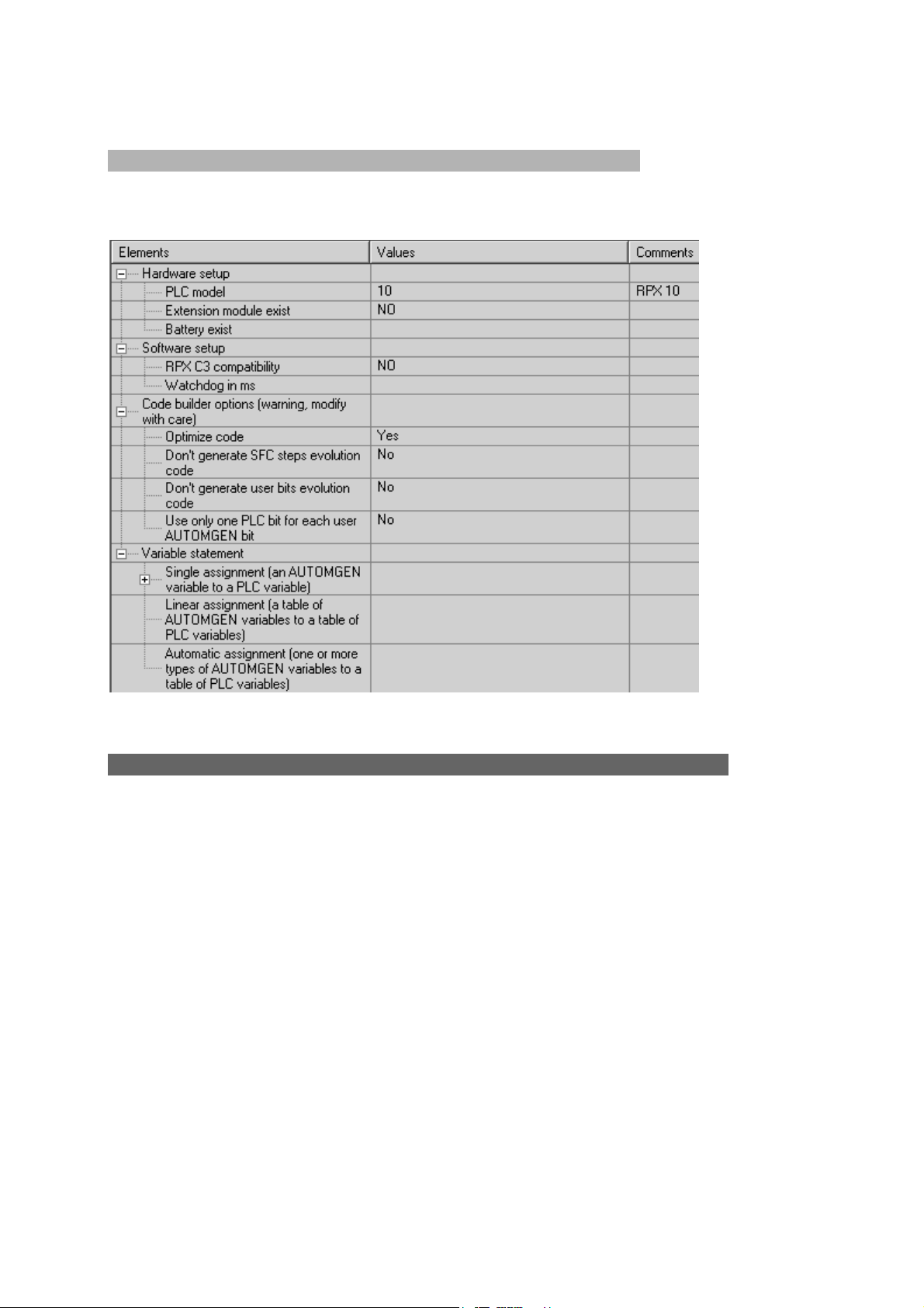
Displaying system elements
By double clicking on « Configuration / Post-processors / <name of post-processor> /
System » the following window opens.
Example of system configuration
Variable functions
Mastering variable functions is one of the fundamental elements for mastering the
use of post-processors.
When the post-processor translates a AUTOMGEN pivot language file into a specific
target language, it must attribute AUTOMGEN variables to the target variables.
For example, if you use the AUTOMGEN word 200 in your application (called M200
or %MW200 in AUTOMGEN) this word must exist in the target memory and thus
must have a name for that target.
AUTOMGEN proposes three types of statements for variable functions.
- single assignment;
- linear assignment
- automatic assignment
Variable functions for a project will be composed of « n » assignments each one
using one of the three types.
AUTOMGEN
7
11 (C)opyright 2004 IRAI
Page 12

Post-processor manual
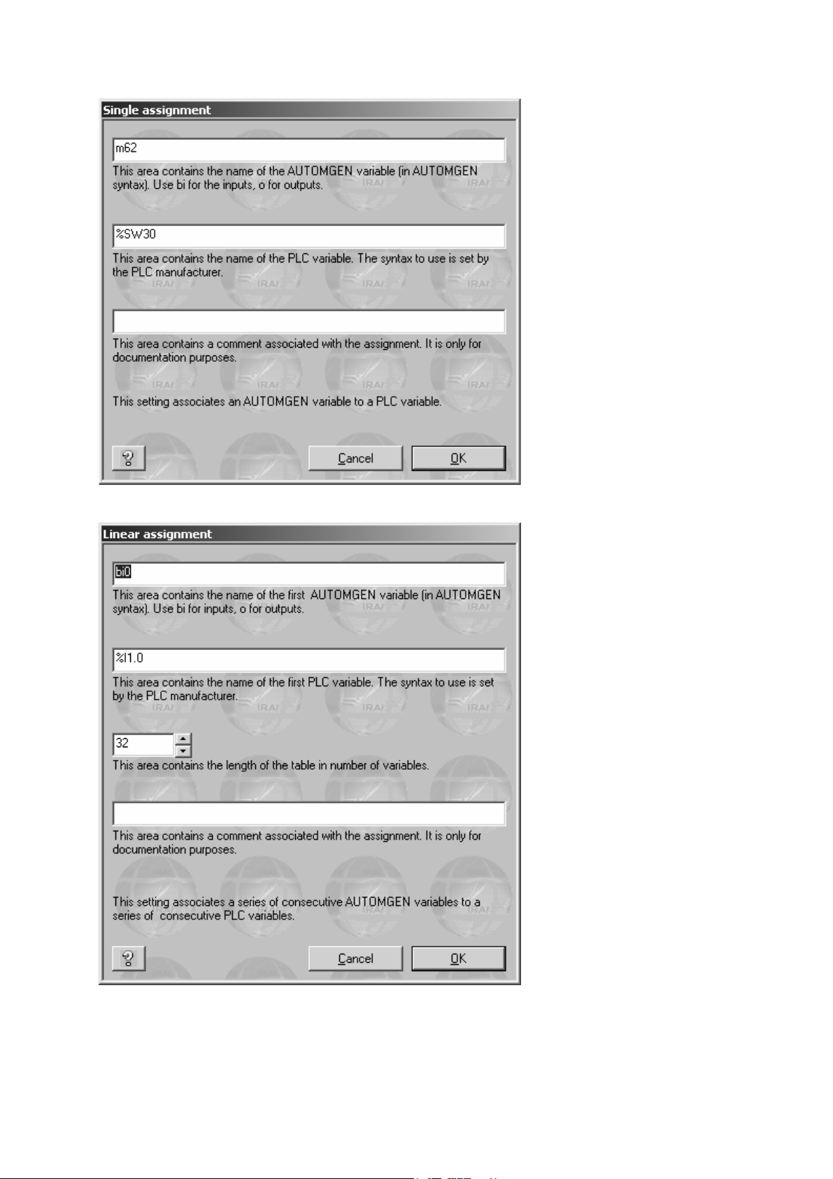
Single assignment
This is used to associate an AUTOMGEN variable to a target variable. It is the
simplest of the statements
It can only be used if a single statement is necessary.
This statement uses two pieces of information. the name of the AUTOMGEN variable
and the name of the target variable.
« Associate this AUTOMGEN variable to that target variable », to effect a single
assignment..
Linear assignment
This form is more evolved than a single assignment.
It is used to associate a series of consecutive AUTOMGEN variables (multiple
variables of the same type where the numbers are in order) to a series of consecutive
target variables.
The assignment is normally used for:
- stating input/output variables;
- stating bit or word tables which must have a fixed address (for example, for a
link with an operator control panel).
This statement uses three pieces of information: the name of the first AUTOMGEN
variable, the name of the first target variable and the dimension of the table in
number of variables.
« Associate this AUTOMGEN variable table in order to that target variable table », to
effect a linear assignment.
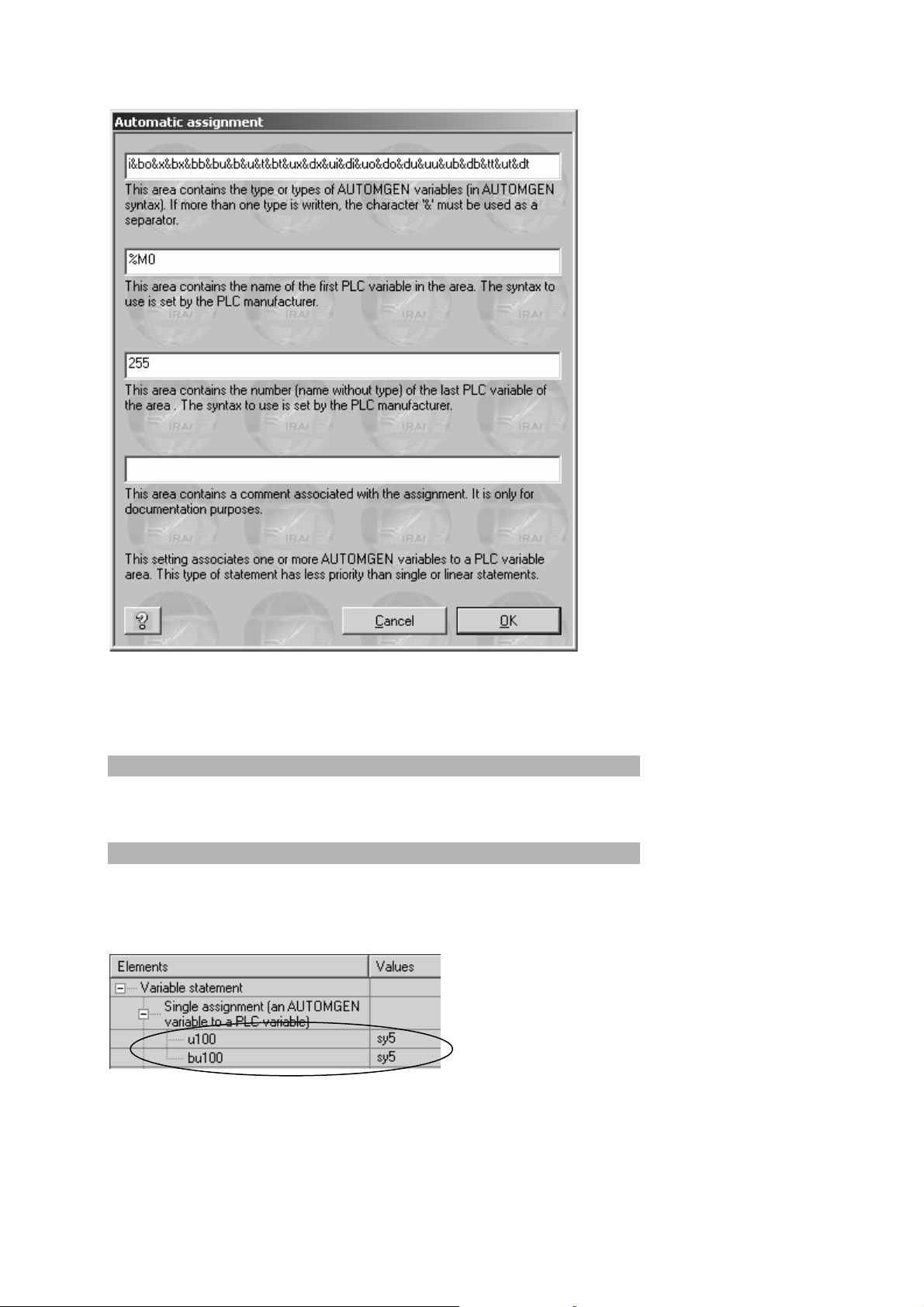
Automatic assignment
This is the most complex and powerful type of statement. It is used to associate one
or more types of AUTOMGEN variables to a range of target variables.
This assignment gives the compiler the task of finding an assignment for each
variable in the generated code (as long as it corresponds to one of the types) of the
statement.
This type of statement is normally used for all AUTOMGEN application variables
where the address of the variable associated in the target does not need a precisely
fixed address.
This statement uses three pieces of information:
- the type of AUTOMGEN variables (see the chapter ) Types of AUTOMGEN
elimination variables
- the name of the first variable of the target range;
- the number of the last variable (included) of the target range.
7
AUTOMGEN
12 (C)opyright 2004 IRAI
Page 13

Post-processor manual
Automatic assignment is not used for a post-processor if another statement has not
been found for a variable. For example, if a linear assignment command sets an
attribution for the words 200 to AUTOMGEN 210, the post-processor will not use
automatic assignment to try and allocate these words.
If multiple automatic assignments exist for the same type of AUTOMGEN variable,
the post-processor will use the first range of target variables until saturation, then the
second until saturation, then the third etc.
If a variable has not been allocated at the end of using all the automatic assignments,
the compiler generates an error message indicating that the variable has not been
set.
« When you find one of these types of variables, use a variable of the target in that
area», to effect an automatic assignment.
Types of AUTOMGEN elimination variables
These are used to state variable functions, they are a subset (because more than
one target variable may be needed to allocate an AUTOMGEN variable) of
AUTOMGEN variable types.
Managing AUTOMGEN boolean variables
One of the basic principles of boolean language translation for the AUTOMGEN
compiler is to be able to access two states for the same boolean variable.
This concept refers to the idea of « execution cycle » : an entity representing the
action created by the target, consisting in reading the application instructions in a
linear mode (from the beginning to the end) and accomplishing the processing they
correspond to.
These two states are set as follows:
1- The immediate state of the variable: the state written for the last instruction
executed by the target transfers that variable either by default to the state of
the variable at the end of the last execution cycle, or if it is the first execution
cycle by default to the initialization state of the variable.
2- The past state of the variable: the state of the variable at the end of the last
execution cycle.
Comments: the two states are only valid for the main application task. Only the
immediate state has meaning for asynchronous tasks.
The code generated by the AUTOMGEN compiler assumes the following:
- assignment of a boolean variable is effected on its immediate state;
- testing of a boolean variable is effected on its past state.
AUTOMGEN
7
13 (C)opyright 2004 IRAI
Page 14

Post-processor manual
These two rules are used to ensure a consistent evolution of boolean applications
and to observe the evolution rules of programs generated by a Grafcet language
description.
The code generated by the post-processor manages recopying of the variable
immediate states to variable past states at cycle end.
When a boolean variable is used in AUTOMGEN two boolean variables are used on
the target.
There are three exceptions:
1- for an all or none input, if no edge test is used, only the past state (« bi ») is
used (economy of a boolean variable).
2- for an all or none output, if no edge test is used, only the immediate state
(« o ») is used.
(this explains why only the « bi » and « o » variables are found in variable attribution
commands).
3- for the ZELIO post-processor, which effects time management of the variables
(almost identical to AUTOMGEN's) only immediate states are used in ZELIO
programming language.
Standard element syntax
« <AUTOMGEN variable name> » refers to the immediate state of a boolean
variable or a numeric variable..
« b<AUTOMGEN variable name> » refers to the past state of a boolean variable.
Special edge syntaxes
« u<AUTOMGEN variable name> » refers to the « rising edge » state of a boolean
variable.
« d<AUTOMGEN variable name> » refers to the « falling edge » state of a boolean
variable.
Special time delay syntaxes
« time <number> » refers to a time delay number.
« tproc<number> » refers to a time delay procedure..
« tcount<number> » refers to a time delay time counter.
Other special syntaxes
(only for specialists)
7
AUTOMGEN
14 (C)opyright 2004 IRAI
Page 15
Post-processor manual
« ac » refers to the 16 bit accumulator.
« al » refers to the 32 bit accumulator.
« af » refers to the float accumulator.
« cf » refers to the carry flag.
« zf » refers to the zero result flag
« sf » refers to the negative result flag.
« of » refers to the overflow flag.
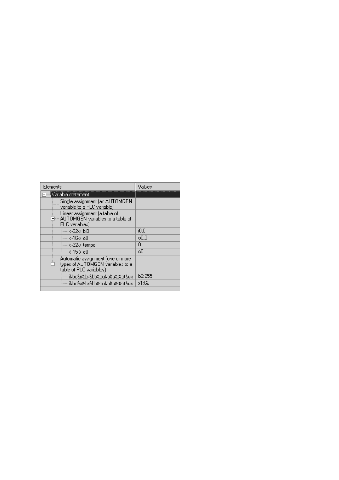
Displaying the variable function elements
By double clicking on « Configuration / Post-processors / <name of post-processor> /
Variable function » the following window opens.
Example of variable functions
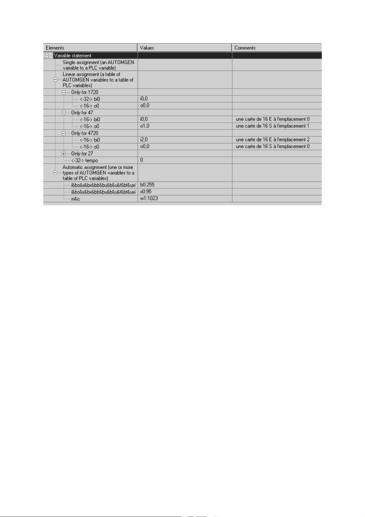
Comment: in the event that the same post-processor can generate code for multiple
types of target (for example multiple types of processor CPU's) the different elements
can be conditioned for all of the target types or for one particular target type. If the
elements are conditioned, they are associated to « Only for xxx » lines. See the
examples below.
7
AUTOMGEN
15 (C)opyright 2004 IRAI
Page 16
Post-processor manual
By clicking on the elements « + » on the tree you open the branches, « - » closes
them.
AUTOMGEN
7
16 (C)opyright 2004 IRAI
Page 17
Post-processor manual
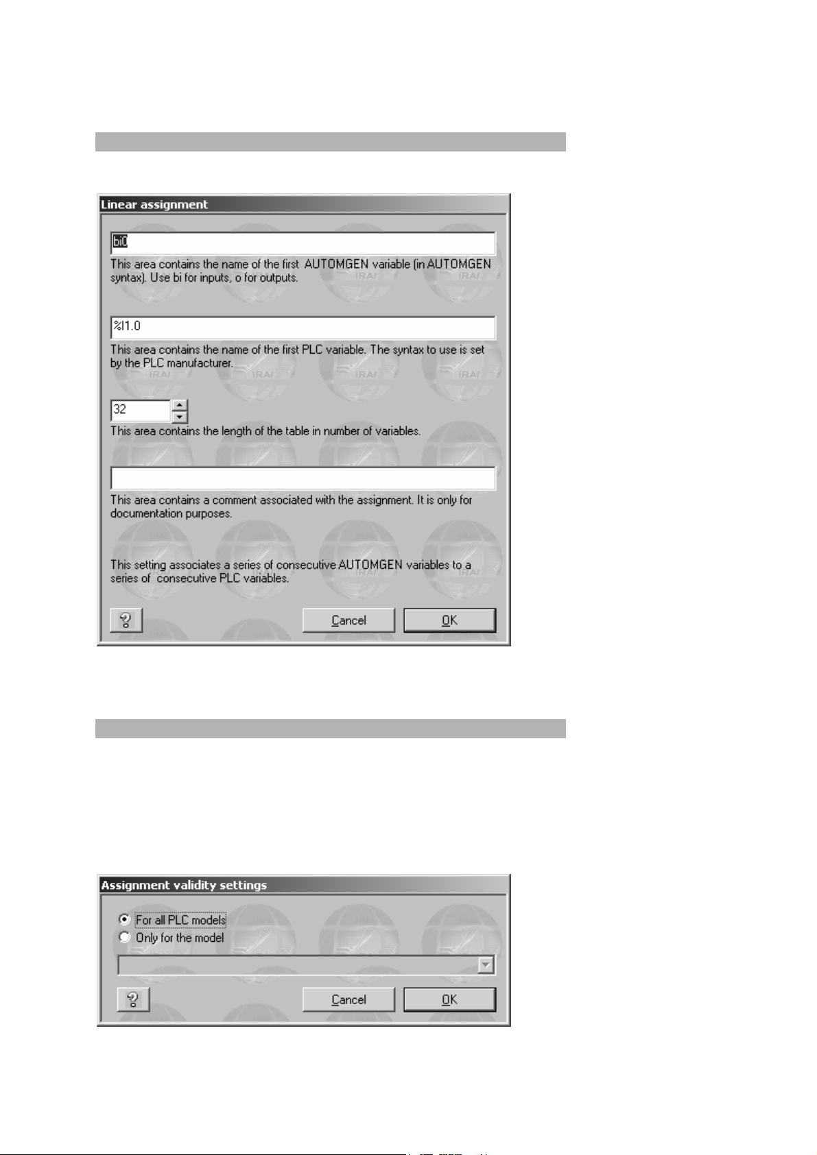
Modifying a variable function element
You can modify the elements by double clicking on them.
Example of a configuration dialogue box for a linear assignment.
Adding a variable function element
To add a new assignment, click with the right side of the mouse on the « Assignment
… » elements of the tree and select « Add » from the menu.
If multiple target types are managed by the post-processor, the following dialogue
box is used to establish if the new assignment is only for one type in particular or all
the types.
AUTOMGEN
7
17 (C)opyright 2004 IRAI
Page 18
Post-processor manual
Single assignment
Linear assignment
7
AUTOMGEN
18 (C)opyright 2004 IRAI
Page 19
Post-processor manual
Automatic assignment
Note that AUTOMGEN variables must always be separated using the « & »
character.
Deleting a variable function element
With the right side of the mouse, click on the variable function element and select
« Delete » from the menu.
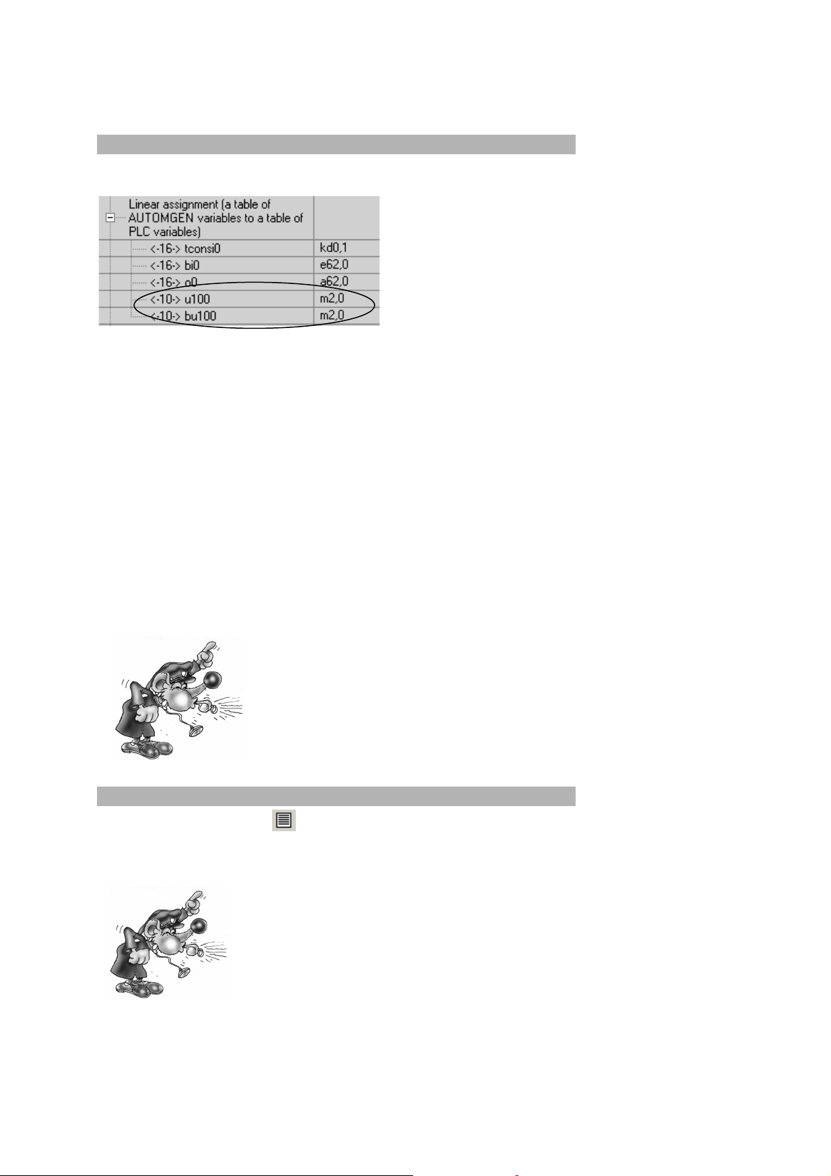
Associating an AUTOMGEN bit to a target system bit
Two statements are necessary, the two state variables of a bit « U » (« u » and
« bu ») must be associated to a target system bit. You must create two single
assignments, for example:
Be careful, when you assign the AUTOMGEN u and bu variable to the same target
system bit, you eliminate the possibility of creating a rising or falling edge test in the
application. You can get around this problem by using the syntax « ↑(u<n>) » or
AUTOMGEN
7
19 (C)opyright 2004 IRAI
Page 20

Post-processor manual
« ↓(u<n>) » (where « <n> » represents the bit number) in the application (this syntax
generates an intermediate bit where the edge will be correctly evaluated).
Associating a table of AUTOMGEN words to a table of fixed target words
Only a single linear statement is necessary for this, for example:
The target words that are allocated must be free from other
assignments or the same target variables may be assigned
twice to different AUTOMGEN variables.
Associating AUTOMGEN words to target analog inputs or outputs
Use linear statements, for example:
AUTOMGEN
7
20 (C)opyright 2004 IRAI
Page 21
Post-processor manual
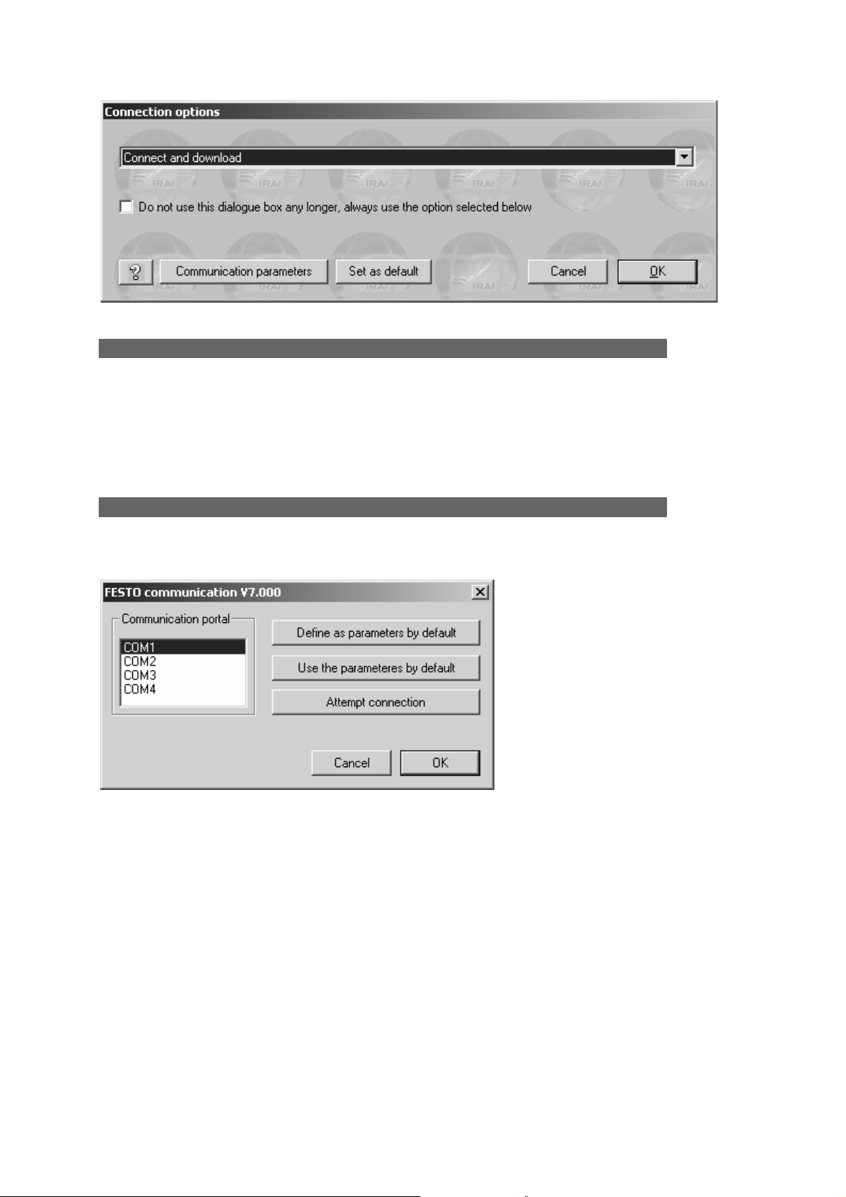
Associating a table of AUTOMGEN bits to a table of target bits
Two linear assignments are necessary, for example: For example:
This example (the immediate states and past states are associated to the same
target variables) does not allow using the edge tests on AUTOMGEN bits u100 to
u109.
Two solutions are possible for getting around this problem:
- use the syntax « ↑(u<n>) » or « ↓(u<n>) » (where « <n> » represents the bit
number) in the application,
- associate the immediate and past state bits to two tables of different bits in the
target.In this case, external access to the application which can be created on
these bits (for example by a dialogue terminal or supervision software) must
comply with the AUTOMGEN philosophy: for reading access for past states,
writing access for immediate states (reading access for immediate states is
possible in practice).
The allocated target bits must be cleaned of any other
assignments or they may assign the same target variables
twice to different AUTOMGEN variables.
See the variable functions in text format
When you click on the icon on the toolbar, you go from « tree » mode to « text »
mode (format of older AUTOMGEN versions). In « Text » format you can copy and
paste information into the configuration files..
Modification to « text » mode must be made by specialists,
inopportune modifications can lead to compiling errors which are
difficult for an inexperienced person to find.
7
AUTOMGEN
21 (C)opyright 2004 IRAI
Page 22

Post-processor manual
Start-up manufacturer code, end manufacturer code
These configuration elements contain machine code for each target in text format.
The syntax to be used in these sections is similar to low level languages that can be
used on each target. Observation of the code generated in pass 1 for each postprocessor allows you to display the syntax to be used.
Reference to an AUTOMGEN variable
Use the syntax « _<AUTOMGEN variable name>_ » to refer to an AUTOMGEN
variable (remember to add the character « b » at the beginning of the variable to
access the past state of a boolean variable. For example « _bu100_ »).
Referring to an AUTOMGEN application symbol
Syntax:
_|symbol name|_
The character « | » is normally associated to key 6 on the keyboard.
Setting and referring to a label
« @<label name> » indicates a jump destination,
« _<label name>_ » refers to a label.
Entering machine code in an application
The key words « #BEGIN_MACHINE_CODE » and « #END_MACHINE_CODE » are
used to enter machine codes in an AUTOMGEN code box.
These two commands must be placed at the beginning of a line, no other characters
should be placed on the same line.
The lines within these two commands establish an area called « Machine language
section ».
The syntax to be used in a machine language section is the same as that used in the
« Begin machine code » and « End machine code » elements.
Selecting connection options
Double click on the element « Configuration / Post-processor / <post-processor
name> / Connection options».
AUTOMGEN
7
22 (C)opyright 2004 IRAI
Page 23
Post-processor manual
Selecting a connection mode
The number of connection modes is based on the post-processor. The « Only
connected » mode is normally used to create a supervising application.
This dialogue box opens automatically when connection to a target is requested. If
you check « Do not open … », it will no longer open automatically. To open it again,
push the [Shift] key or launch the connection command or the « Go » command.
Setting communication module parameters
Double click on the element « Configuration / Post-processor / <post-processor
name> /Communication module».
Example of setting communication module parameters
The current configuration can be set as a default configuration (for new projects) or
default reset.
A connection test can be created.
AUTOMGEN
7
23 (C)opyright 2004 IRAI
Page 24
Post-processor manual
Post-processor PL7
This post-processor is used to program the processors MODICON
TELEMECANIQUE SCHNEIDER TSX 37, (TSX MICRO) and TSX 57 (TSX
PREMIUM).
Communication module
The UNITELWAY SCHNEIDER driver must be installed on the
computer (locally) to be able to communicate with processors
SCHNEIDER TSX 37 and TSX 57. Drivers adapted to one or more
versions of WINDOWS are on the CD-ROM and can be downloaded
from the IRAI site. www.irai.com.
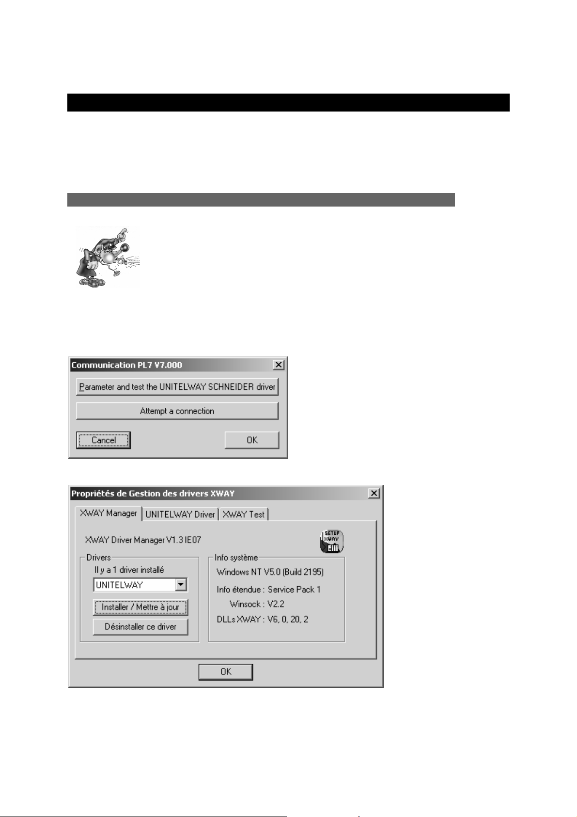
The communication module uses the driver conceived for SCHNEIDER
AUTOMATION. Click on « Setting parameters and testing … » to directly access
SCHNEIDER communication driver menus.
Setting communication module parameters
UNITELWAY communication module properties
AUTOMGEN
7
24 (C)opyright 2004 IRAI
Page 25
Post-processor manual
Generating an executable file
The post-processor can generate a binary file which can be directly downloaded in
the processor (only available on TSX 37, not available on TSX 57) or a file which can
be imported in the SCHNEIDER tools (available for TSX 37 and TSX 57). The first
solution is preferable (saves time, easier to use).
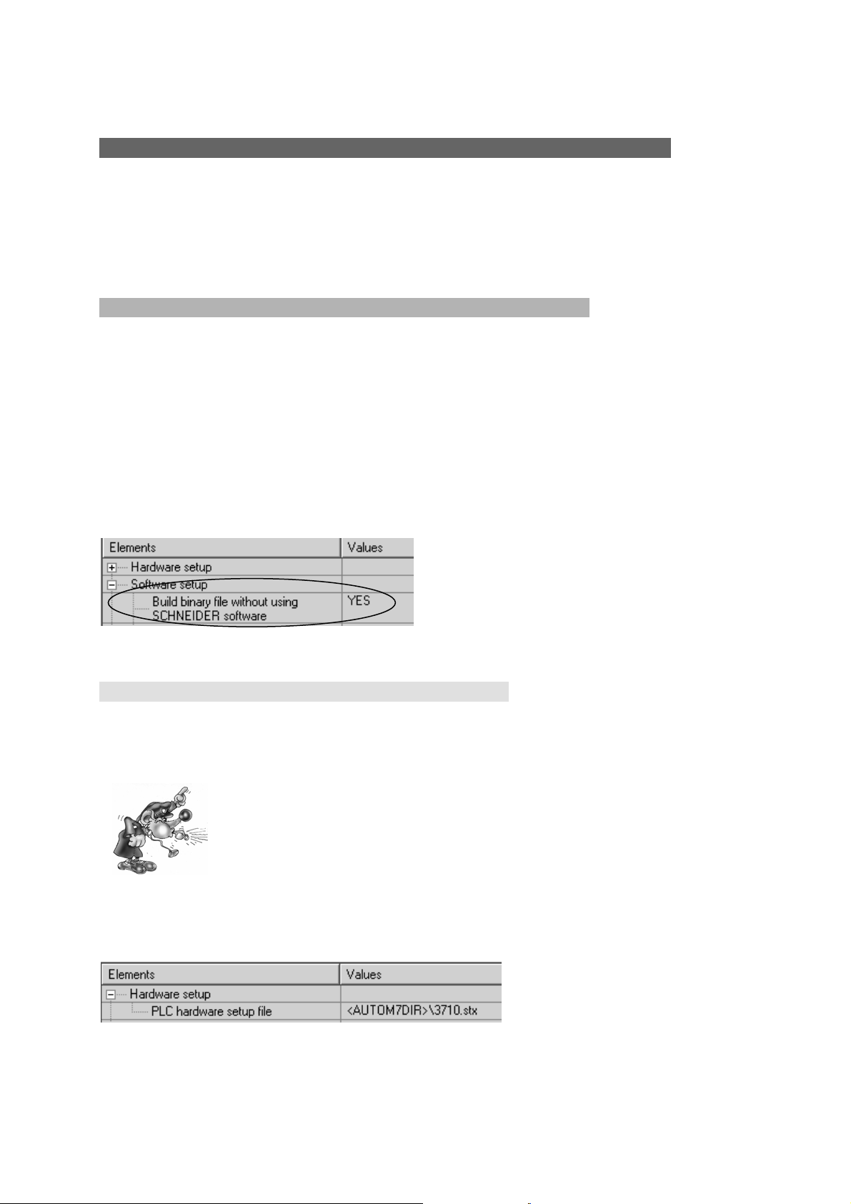
The mode selection is made in the post-processor software configuration.
Direct generation of a binary file
This mode is highly recommended for TSX 37.
It has the following restrictions:
- sub-program instruction cannot be used;
- it does not support specific instructions (for example communication or PID).
If your application must use very specific elements, use one of the importation
methods described above.
Selecting automatic generation of a binary file.
Processor configuration file
For the basic versions of TSX 37-05 and TSX 37-08 (with only one input/output card),
files 3705.stx and 3708.stx are provided in the AUTOMGEN installation directory.
If a configuration file is not created, the processor TOR outputs will
not be activated.
Once the file is created or downloaded (see above), give an access path to the file in
the following configuration element:
File name containing the configuration
7
AUTOMGEN
25 (C)opyright 2004 IRAI
Page 26

Post-processor manual
There are three possible methods for obtaining a configuration file:
Download the configuration file from the IRAI site
1- download a file corresponding to the configuration of your processor from the
IRAI site: www.irai.com
, « Download / AUTOMGEN7 / configuration files for
TSX 37 processor » section (recommended if the configuration file is present
on the site),
2- recopy the downloaded file without unzipping it (« .STX » files are zipped files)
into the AUTOMGEN installation directory or put it into AUTOMGEN project
resources.
If you unzip the « .STX » file the post-processor will not be able to
use it.
Creating a file with the SCHNEIDER programming tools
SCHNEIDER (PL7MICRO V3.1, PL7JUNIOR V3.1 or PL7PRO V3.4) software tools
can be used.. Files created with other versions may not work, in this case, the
processor goes into error mode when the application is downloaded (« ERR » light
goes on on the processor).
To create an « .STX » file :
1- launch one of the SCHNEIDER tools, create an application following the rules
below:
o select your processor's type of CPU and always select the 1.0 version
of the CPU;
o select the input/output card/s on your processor and if necessary set
their parameters;
2- save the file created in the AUTOMGEN installation directory or enter it into
AUTOMGEN project resources.
AUTOMGEN
7
26 (C)opyright 2004 IRAI
Page 27

Post-processor manual
Send an e-mail to IRAI to obtain the configuration file
1- send an e-mail to IRAI requesting a configuration file, the following information
needs to be provided:
o the type of CPU TSX 37-05, 37-08, 37-10, 37-21 or 3722,
o the position and exact type of input/output cards (DMZ …)
2- when you receive the file, recopy it into the AUTOMGEN installation directory
(without unzipping it) or put it into AUTOMGEN project resources.
Generating an « .FEF » executable file
In this mode, importation in the SCHNEIDER programming tools (PL7 MICRO (TSX
37), PL7 JUNIOR (TSX 37 or TSX 57) or PL7 PRO (TSX 37 or TSX 57) can be
automatic or manual.
Manual importation
Selecting manual importation mode
You must select a file name which will be exported for AUTOMGEN:
Selecting a file for exporting to SCHNEIDER software workgroup
Procedure:
1- Compile the application in AUTOMGEN using the « Compile » command from
the « Program » menu or clicking on the
button on the toolbar,
2- Launch a SCHNEIDER software workgroup, create a new project and use the
« Import an application» command from the « File » menu,
3- When the importation process is finished, transfer the application to the
processor.
AUTOMGEN
7
27 (C)opyright 2004 IRAI
Page 28

Post-processor manual
4- To obtain a dynamic display in AUTOMGEN, click the « Go » button on the
toolbar and select the « Only connect» connection mode.
Automatic importation
The SCHNEIDER software tool will be launched automatically. Only a limited number
of SCHNEIDER software can be used. The type and version of SCHNEIDER
software must be set in the software configuration.
Selecting the type and version of SCHNEIDER software
Operation of the automatic importation procedure with other SCHNEIDER software
versions is not guaranteed.
Procedure to be effected only once.
1- Launch a SCHNEIDER programming tool and create a new application.
2- Configure the application: the type of processor, input/output cards etc.
3- Save the file you have created;
4- Give the complete access path to that file in the « hardware configuration»
section of the « System» element, for example:
Create an application for each execution:
Launch the SCHNEIDER software tool (if you have not already done so);
Click the « GO » button on the AUTOMGEN toolbar.
7
AUTOMGEN
28 (C)opyright 2004 IRAI
Page 29

Post-processor manual
Using interrupt tasks
When setting a task type sheet, you can enter AUTOMGEN low level language or
machine language for a processor task. The table below provides the
correspondence in the number of tasks and the type of interrupr task of the
processor.
Task number
(AUTOMGEN sheet)
Processor TSX 37 task
type
Processor TSX 57 task type
0 Fast task Fast task
1 EVT1 EVT0
2 EVT2 EVT1
3 EVT3 EVT2
etc…
Specific examples
These examples are in the directory « <AUTOMGEN installation
directory> /Examples/Post-processors/PL7 ».The files have the same names as the
titles of the following chapters.
Analog inputs/outputs
This example illustrates the use of analog inputs/outputs.
Stating analog inputs/outputs on processor TSX 37-22
Fast counter TSX 37-10
This example illustrates the use of a fast counter on a TSX 37-10 processor.
Fast counter TSX 37-10 used in counting
This example illustrates the use of a fast counter on a TSX 37-10 processor in
counting mode.
Fast counter TSX 37-22
This example illustrates the use of a fast counter on a TSX 37-22 processor.
7
AUTOMGEN
29 (C)opyright 2004 IRAI
Page 30

Post-processor manual
ASI
Example of using ASI inputs/outputs
MAGELIS
Example of using a MAGELIS terminal
AUTOMGEN
7
30 (C)opyright 2004 IRAI
Page 31

Post-processor manual
y y y y
y
Post-processor PL72
This post-processor is used to program TELEMECANIQUE SCHNEIDER TSX 17-20
(with PL72 cartridge), TSX 27, TSX 47 and TSX 47-20 processors.
Selecting processor type
Use the « Configuration / Post-processor / PL72 / System / Hardware configuration»
browser element to select the type of processor.
Specific syntax elements
Calling up PL72 function blocks
The following syntaxes are used to call up time delay, text and fast counter (TSX 17-
20) blocks in a text format used in the « Begin machine code », « End machine
code » elements and sections in machine language.
Time delay block
x.Tn=y
PL72 equivalent:
Text block
a+b+c+d.TXTn=x:y
PL72 equivalent:
a TXT
b
c
d
Tn Tn Tn Tn
E E DD
C C
R
S
O
I
D
E
x x x x
x
7
AUTOMGEN
31 (C)opyright 2004 IRAI
Page 32

Post-processor manual
y
y
Fast counter block
a+b+c+d.FC=x:y:z
PL72 equivalent:
R
a FC
P
b
E
D
x
c
d
V
C
F
z
WEEK type time/date block (only on TSX 17-20)
a.H,W (days), (start time), (end time)=x :y :z
« days » represents the days of the week, this is an encoded value on 7 bits, each bit
represents a day of the week. The day is active if the bit 1.b0 corresponds to Sunday
and b6 to Saturday. For example, to validate Monday and Wednesday the value 2
3
2
must be written: 2 + 8 = 10. To validate the seven days of the week: the value is
1
+
127.
« start time » and « end time » are expressed as HH:MM: hours and minutes:
YEAR type time/date block (only on TSX 17-20)
a.H,Y,(start date),(end date)=x :y :z
« start date » and « end date » are expressed as DD:MM: day and month.
PL72 equivalent:
a
HOR
<
=
>
x
z
7
AUTOMGEN
32 (C)opyright 2004 IRAI
Page 33

Post-processor manual
Using a fast task
A« Task » type sheet bearing the number « 1 » is used to associate literal code or
PL72 code written on the sheet to the fast task. The sheet must not contain anything
other than low level literal code or PL72 code written in an organizational chart
rectangle.
Communication module
Setting communication module parameters
If you connect the PC on the processor console outlet, you must select « Console
outlet».
Do not check « Always attempt 19200 baud connection » unless your processor is a
recent TSX 17-20 (this option is used for a faster dialogue between the PC and
processor).
The « UNITELWAY » mode is used to connect the PC to a UNITELWAY coupler. In
this case, the speed must correspond to the coupler configuration.
If you check « Always attempt 19200 baud connection » and
your TSX 17-20 does not support 19200 baud communication
the connection will fail.
If the mode does not correspond with the connection (for
example, UNITELWAY mode selected and a connection on the
console processor) the connection will fail.
Specific examples
These examples are in the directory « <AUTOMGEN installation
directory> /Examples/Post-processors/PL72 ».The files have the same names as the
titles of the following chapters.
7
AUTOMGEN
33 (C)opyright 2004 IRAI
Page 34

Post-processor manual
Analog inputs/outputs
To use the analog outputs on a TSX 17-20 processor you must:
- state the analog input/output blocks in the « System » element of the
configuration .
- associate one or more AUTOMGEN variables to the TELEMECANIQUE
input/output words (IW and OW).
Example:
- processor TSX 17-20 using a block of 4 analog inputs (code 27) in position 1
and a block of 2 analog outputs (code 21) in position 2:
- the program will simply recopy the state of the first analog input on the first
analog output. it will also compare the second analog input with the value 500
(arbitrary value) and position two boolean outputs: O0 if the input is less than
500 and O1 if the input is greater than or equal to 500.
Statement of two extension modules
Assigning variables
These two statements associate the AUTOMGEN words M200 to M203 to processor
variables IW1,0 to IW1,3 as well as AUTOMGEN variables M204 and M205 to
processor variables OW2,0 and OW2,1.
Fast counter
The goal is to count 200 pulses on the fast counter. The current value of the fast
counter will be recopied in AUTOMGEN word M200. Output O5 will be activated by a
interrupt task at the end of the count.
AUTOMGEN
7
34 (C)opyright 2004 IRAI
Page 35

Post-processor manual
Setting fast counter parameters
Text blocks and xbt
The goal is to dialogue with an XBT connected on the console port of processor TSX
17-20.
Inputs I0 to I3 start displaying messages number 0 to number 3 registered in the
XBT.
Text block TXT1 will be used to dialogue on the console port.
The message format to send to the XBT for displaying a message is as follows:
ESC V xxx LF CR
xxx represents the number of the message encoded in three character decimals.
Allocation of a word table for exchanges
7
AUTOMGEN
35 (C)opyright 2004 IRAI
Page 36

Post-processor manual
Setting text block parameters
7
AUTOMGEN
36 (C)opyright 2004 IRAI
Page 37

Post-processor manual
UNITELWAY text blocks
The goal is to use a UNITELWAY coupler to acquire a table of 3 words on a target
processor. The UNITELWAY coupler is installed as a first extension, it will be
configured as the master to use two slaves. Processor Iu will be slave number 1.
Configuration of an UNITELWAY coupler
AUTOMGEN
7
37 (C)opyright 2004 IRAI
Page 38

Post-processor manual
Setting parameters for two text blocks
7
AUTOMGEN
38 (C)opyright 2004 IRAI
Page 39

Post-processor manual
Attribution of a word table for exchanges
TOR extension module
This example illustrates the configuration of a TOR extension module. We are using
a basic module equipped with 16 inputs and 12 outputs and an extension module
equipped with 10 inputs and 8 outputs.
Setting the extension module
Assigning variables
Conversion
Shows how to call up the PL72 language conversion functions.
Time/date
Example of using a time/date function block.
AUTOMGEN
7
39 (C)opyright 2004 IRAI
Page 40

Post-processor manual
Post-processor S7200
This post-processor is used to program SIEMENS S7200 (all 2xx CPU's) processors
.
Selecting CPU type
Use the « Configuration / Post-processor / STEP7 (S7200) / System / Hardware
configuration» browser element to select the type of CPU.
Communication module
Setting communication module parameters
Be sure to set the slave number so it corresponds with the processor configuration.
Specific example
This example is in the directory « <AUTOMGEN installation
directory> /Examples/Post-processors/S7200 ».The file has the same name as the
title of the following chapter.
Interrupt task
Example of calling up an interrupt task
AUTOMGEN
7
40 (C)opyright 2004 IRAI
Page 41
Post-processor manual
Post-processor ABB
This post-processor is used to program ABB CS31 and AC31 processors .
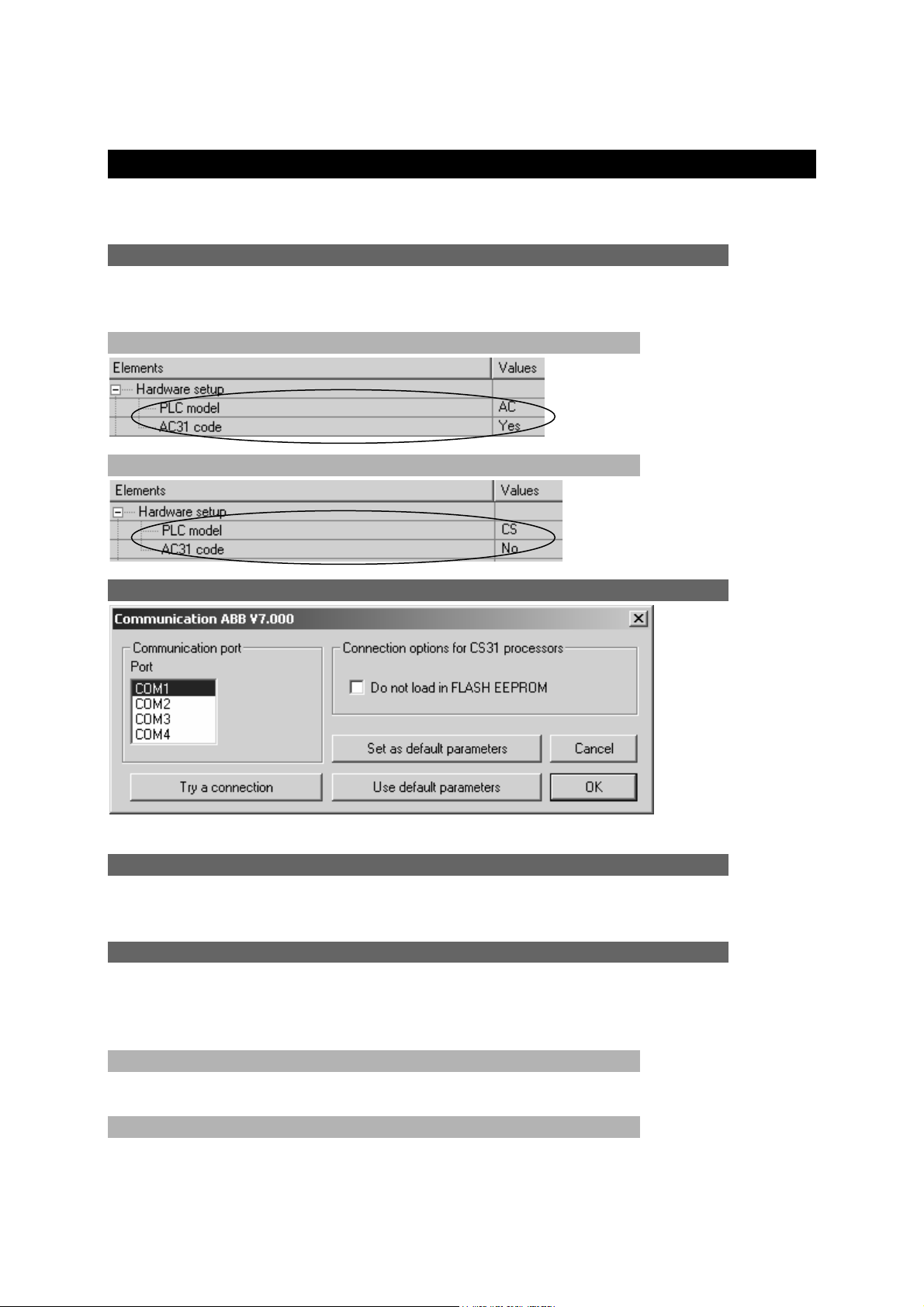
Selecting processor type
Use the « Configuration / Post-processor / ABB / System / Hardware configuration»
browser element to select the type of processor.
Processor AC31
Processor CS31
Communication module
Setting communication module parameters
Utility
The « Configuration / Post-processor / ABB / Terminal emulator » browser element
is used to access a terminal emulator for dialoguing with the processor.
Specific examples
These examples are in the directory « <AUTOMGEN installation
directory> /Examples/Post-processors/ABB ». The files have the same names as the
following chapters:
Analog inputs/outputs
The example illustrates the use of an analog extension module on processor AC31.
Interrupt
The example illustrates the use of interrupt tasks on processor AC31.
7
AUTOMGEN
41 (C)opyright 2004 IRAI
Page 42
Post-processor manual
Post-processor GE-FANUC / ALSPA
This post-processor is used to program GE-FANUC 90 MICRO and 9030 or ALSPA
8005 and 8035 processors.
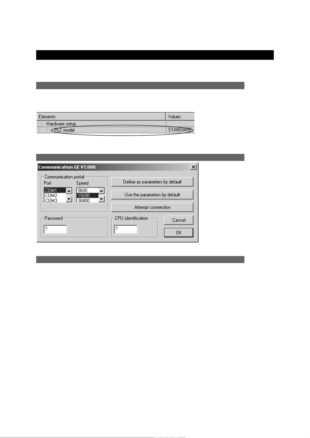
Selecting processor type
Use the « Configuration / Post-processor / GE-FANUC / System / Hardware
configuration» browser element to select the type of processor.
Select standard for CPU's other than 350, 351 or VERSAMAX.
Communication module
Setting communication module parameters
Utility
The « Configuration / Post-processor / GE-FANUC / Hardware configuration &
diagnostic » browser element is used to access a configuration and diagnostic utility.
AUTOMGEN
7
42 (C)opyright 2004 IRAI
Page 43

Post-processor manual
Post-processor STEP5
Communication module
Setting communication module parameters
Application structure
SIEMENS STEP5 language is organized in program and data blocks. AUTOMGEN
applications translated by the STEP5 post-processor are broken down into multiple
blocks. By default, the post-processor uses the following blocks
- OB1 organization block this block calls up all the blocks that must be cyclically
processed.
- OB20, OB21, OB22 : blocks executed when the processor starts. These blocks set
a bit to activate the initial Grafcet steps.
The PB blocks are used to process pre-settings, to manage the evolution of boolean
variables and time delays.
The FB or FX blocks are used for the code issued by the application and for the code
written in the « .SRT » and « .END » files. An FB or FX file is created for each
application sheet.
In addition, the sheets can be directly associated to a block of codes or data.
If the volume of generated code is too much for a block (for example, code issued
from a sheet containing a voluminous program), the post-processor automatically
uses a new block.
By default, the post-processor uses the blocks PB1 to PB255 and FB1 to FB239
when needed.
These values can be modified, (see the chapter ). Selecting program blocks to use
AUTOMGEN
7
43 (C)opyright 2004 IRAI
Page 44
Post-processor manual
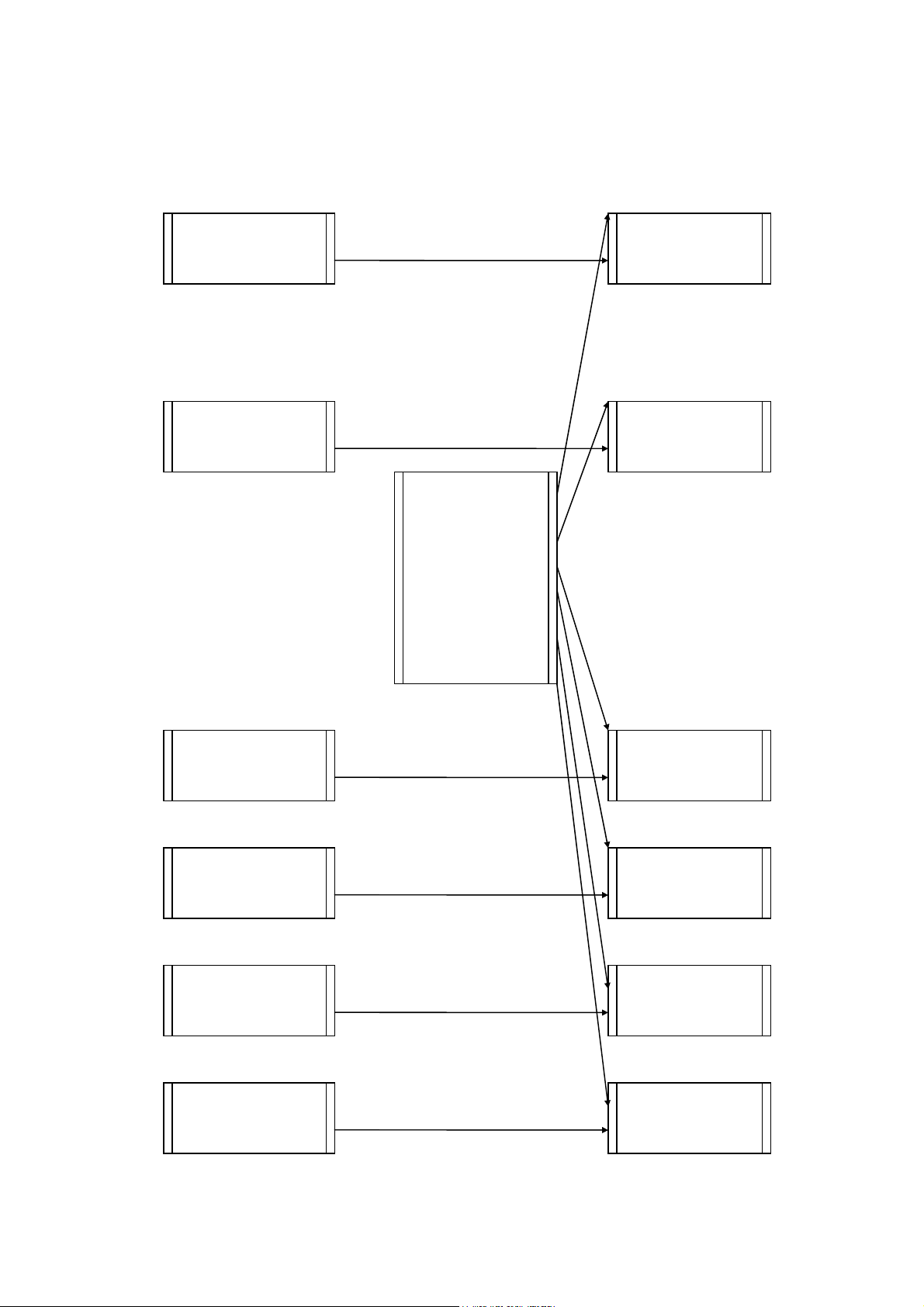
The figure below illustrates the structure of code generated by the SIEMENS postprocessor.
Begin machine
code
Block FB or FX
Block PB Presettings
Block OB1
Application
sheets
n blocks FB or
FX
variables
Block PB Evol. of boolean
variables.
Block PB Evol. of time
End machine
code
Block FB or FX
AUTOMGEN
7
44 (C)opyright 2004 IRAI
Page 45

Post-processor manual
Selecting program blocks to use
Blocks PB1 to PB 255 and FB 1 to FB 239 are used by default. Three configuration
elements are used to select other blocks.
Selecting data blocks
Block DB 3 is used by default for numeric variables. This command is used to select
another block.
Changing the data block involves two other modifications.
- in the begin machine code, it is necessary to create corresponding data blocks,
- it is necessary to select the data block in the dialogue module parameter settings.
AUTOMGEN
7
45 (C)opyright 2004 IRAI
Page 46

Post-processor manual
Selecting processor type
Associating code written on a sheet to a program block
When writing low level literal code or machine code on an organizational chart on a
« Task » type sheet, associate the code to a STEP5 block.
The task number determines the block type and number.
The generated code for that sheet must take into account the block type and the
instructions used in that block type (the set of instructions for blocks OB and PB is
limited).
The table below provides the correspondence between the value « n » and the block.
Task number STEP5 block
0 to 255 OB 0 to OB 255
256 to 511 PB 0 to PB 255
512 to 767 FB 0 to FB 255
768 to 1023 FX 0 to FX 255
1024 to 1279 DB 0 to DB 255
1280 to 1535 DX 0 to DX 255
Specific syntaxes
Setting blocks
The command « $BLOCK <block type> <number>» is used to set the beginning of a
program or data block.
The block type can be « OB », « FB », « FX », « PB » for the code or « DB », « DX »
for the data..
The block number is a value between 0 and 255. Blocks « FX » and « DX » can only
be used on processors 135U and 155U. The command « BE » indicates the end of a
block.
7
AUTOMGEN
46 (C)opyright 2004 IRAI
Page 47

Post-processor manual
Example:
$BLOCK DB1
...
$BE
$BLOCK OB1
...
$BE
the commands « KH= », « KY= », « KC= », « KM= » and « KF= » add constants to
the data blocks DB.
« KH= » adds a 16 bit constant expressed in hexadecimal.
« KY= » adds a 16 bit constant expressed in the form of two values.
between 0 and 255 separated by a comma.
« KC= » adds a series of characters surrounded by the characters
« ’ » (apostrophe).
« KM= » adds a 16 bit constant expressed in binary.
« KF= » adds a 16 bit constant expressed in signed decimal.
Example:
$BLOCK DB4
KH= 1234
KY=100.5
KC= ‘This is a text’
KM=11111111 00000000
KF=-200
$BE
Blocks FB and FX
SIEMENS language blocks FB and FX can have parameters.
Call up
If the parameters need to go to a functional block , use the following syntax:
- call up needs to be followed by the character « * »,
- the following line must contain a jump instruction « SPA » to the line beyond
the parameters;
- the following lines must contain the parameters preceded by the mnemonic
« U » for bits or « L » for words. The constants must be written in the form
« Kx=value» (x is the type of constant, see the chapter ). Setting blocks
Example of calling up a functional block without parameters:
SPA FB 5
7
AUTOMGEN
47 (C)opyright 2004 IRAI
Page 48

Post-processor manual
Examples of calling up a functional block with parameters:
SPA FB 242*
SPA=_label_
L MW10 ; first parameter
L MW12 ; second parameter
U M0.0 ; third parameter
L MW14 ; fourth parameter
L MW16 ; fifth parameter
@label
SPA FB200*
SPA=_label2_
KY=0,4 ; Example of a constant parameter
@label2
Writing
In blocks FB and FX mnemonics must be used ending with the character '=' followed
by a parameter number (1=first parameter).
Example of a two parameter function block (first parameter recopied in the second):
$BLOCK FB 100
L=1
T=2
$BE
AUTOMGEN
7
48 (C)opyright 2004 IRAI
Page 49

Post-processor manual
Post-processor TSX 07
This post-processor is used to program the processors MODICON
TELEMECANIQUE SCHNEIDER TSX 07.
Communication module
The UNITELWAY SCHNEIDER driver must be installed
on the computer (locally) to be able to communicate with
processors SCHNEIDER TSX 07. Drivers adapted to
one or more versions of WINDOWS are on the CDROM and can be downloaded from the IRAI site:
www.irai.com
are incompatible with certain types of TSX 07
processors (TSX 0720 … and TSX 0721…are
incompatible with WINDOWS ME, WINDOWS 2000 or
WINDOWS XP).
The communication module uses the driver conceived for SCHNEIDER
AUTOMATION. Click on « Setting parameters and testing … » to directly access
SCHNEIDER communication driver menus.
. Be careful, some versions of WINDOWS
Setting communication module parameters
UNITELWAY communication module properties
7
AUTOMGEN
49 (C)opyright 2004 IRAI
Page 50

Post-processor manual
Post-processor PS3-PS4
This post-processor is used to program KLOCKNER-MOELLER PS3 and PS4
processors..
Communication module
Setting communication module parameters
AUTOMGEN
7
50 (C)opyright 2004 IRAI
Page 51

Post-processor manual
Post-processor PS4
This post-processor is used to program MOELLER PS4-200, PS4-300 and PS416
processors. MOELLER SUCOSOFT S40 V5 or higher software must be used (the
demo version of this software can be used).
Module de communication
Setting communication module parameters
Transferring programs to MOELLER SUCOSOFT software
In the element below you create a file used for exchange between AUTOMGEN and
SUCOSOFT. This file will be generated after compilation in AUTOMGEN.
AUTOMGEN
7
51 (C)opyright 2004 IRAI
Page 52

Post-processor manual
Proceed as follows to import the file generated by AUTOMGEN in the MOELLER software then inject it in the processor.
- launch SUCOSOFT,
- create a new project,
- with the right side of the mouse click on the topology configuration in
SUCOSOFT and select the option « Export/Import / Import IEC/EN 61131-3
sources»,
- enter the name of the file exported by AUTOMGEN,
- double click on « _MAIN » which appears on the list,
AUTOMGEN
7
52 (C)opyright 2004 IRAI
Page 53

Post-processor manual
- in the « Special », menu select « Code generation »,
- answer « Yes » to :
- then « OK » at :
- in the« Generation » menu, select « Program parameter settings … »,
AUTOMGEN
7
53 (C)opyright 2004 IRAI
Page 54

Post-processor manual
- Select an appropriate size to store all the internal variables (%M) of your
application,
- In the «Generation » menu, select « Generate program code »,
- If there are no compilation errors, you can transfer the application to the
processor. In the « Tools » menu, select « Test and start »,
- In the « Device » menu, select « Transfer/File Manager »,
AUTOMGEN
7
54 (C)opyright 2004 IRAI
Page 55

Post-processor manual
- Click on transfer,
- At the end of the transfer disconnect from the SUCOSOFT software to be
able to connect AUTOMGEN to the processor and activate the dynamic tuning
mode
AUTOMGEN
7
55 (C)opyright 2004 IRAI
Page 56

Post-processor manual
Post-processor RPX
This post-processor is used to program CROUZET RPX processors. .
Selecting processor type
Use the « Configuration / Post-processor / RPX / System / Hardware configuration»
browser element to select the type of processor.
Communication module
Setting communication module parameters
Utility
The « Configuration / Post-processor / RPX / Terminal emulator » browser element
is used to access a terminal emulator for configuring processor communication
couplers.
AUTOMGEN
7
56 (C)opyright 2004 IRAI
Page 57

Post-processor manual
Post-processor PL71
This post-processor is used to program the processors SCHNEIDER TSX 17-10 and
TSK 17-20 (without PL72 cartridge).
Selecting processor type
Use the « Configuration / Post-processor / PL71 / System / Hardware configuration»
browser element to select the type of processor.
Communication module
Setting communication module parameters
(For more information, please See the configuration of the
PL72)
Fast counter task
A task type sheet bearing the number 1 will be associated to the processor fast
counter task.
Specific examples
These examples are in the directory « <AUTOMGEN installation
directory> /Examples/Post-processors/PL71 ».The files have the same names as the
titles of the following chapters.
Counting
Since increments and decrements of PL71 counters are limited (only on the rising
edge) in relation to AUTOMGEN and TSX processor possibilities it is necessary to
use machine language code if you want to use them (see the example contents).
7
AUTOMGEN
57 (C)opyright 2004 IRAI
Communication module
Page 58

Post-processor manual
Fast counter
The goal is to count 200 pulses on the fast counter. Output O5 will be activated by a
interrupt task at the end of the count.
AUTOMGEN
7
58 (C)opyright 2004 IRAI
Page 59

Post-processor manual
Post-processor PB
This post-processor is used to program SCHNEIDER APRIL PB processors .
Selecting processor type
Use the « Configuration / Post-processor / PB / System / Hardware configuration»
browser element to select the type of processor.
Communication module
Setting communication module parameters
Specific syntaxes
The command « $ORG=xxxx » is used to set the beginning of the assembly address,
the starting assembly address is set at 0C30;
Example:
$ORG=1C30
The command « $TOP=xxx » sets the maximum address for the page jump. It sets
the three digits of address lower weight, below these a page jump is automatically
generated by the assembler.
The command « $CONST=xxxx,yyyy » sets the begin and end address for constant
storage. The constants are stored in a table outside the program.
The command « WORD xxxx » enters the value xxxx (four hexadecimal digits) in the
program.
The command « ADR xxxx » enters the address of variable xxxx (four hexadecimal
digits) in the program.
The syntax #nnnn is used to refer to a constant value.
AUTOMGEN
7
59 (C)opyright 2004 IRAI
Page 60

Post-processor manual
For example:
apl #1234 ; puts constant 1234 (hexadecimal) in the accumulator.
AUTOMGEN
7
60 (C)opyright 2004 IRAI
Page 61

Post-processor manual
Post-processor SMC
This post-processor is used to program SCHNEIDER APRIL SMC processors .
Selecting processor type
Use the « Configuration / Post-processor / SMC/ System / Hardware configuration»
browser element to select the type of processor.
Communication module
Setting communication module parameters
Specific syntaxes
The command « $SEQ » indicates the beginning of a boolean area.
The command « $CAL » starts a calculation area.
The command « $PRD » starts a variable presetting area.
Boolean variables can be used which are bistable or monostable regardless of the
SMC language conventions. The character « ! » before the sign « = » sets the
variable to bistable (set to one or reset), the character « ? » before the sign « = » sets
the variable to monostable (assignment or complement assignment).
The syntax « SS.cccccccc » is used to write a security sequence (necessary on
processors SMC 25 and 600), « cccccccc » represents a program name with a
maximum of 8 characters.
AUTOMGEN
7
61 (C)opyright 2004 IRAI
Page 62
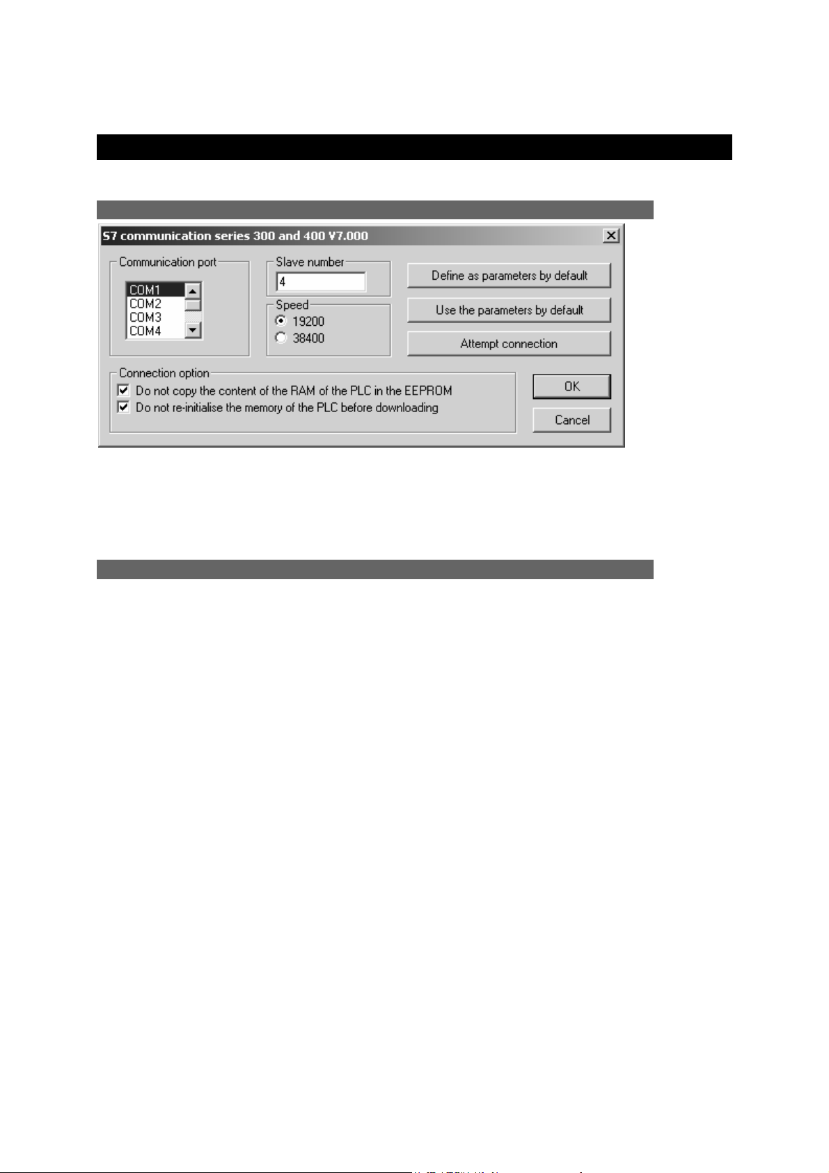
Post-processor manual
Post-processor S7300
This post-processor is used to program SIEMENS S7300 processors .
Communication module
Setting communication module parameters
The slave number must correspond with that set as a parameter for the processor.
Specific syntaxes
The command « $BLOCK <block type> <number>» is used to set the beginning of a
program or data block.
The block type can be « OB », « FB », « FC », « SFC » « SFB » for the code or
« DB » for the data. The block number is a value between 0 and 65535. The
command «$ENDBLOCK » indicates the end of a block.
Example:
$BLOCK DB1
...
$ENDBLOCK
$BLOCK OB1
...
$ENDBLOCK
The following syntax is used to state the variables for a block:
For an input variable:
$VAR-type nature {:=initialization}
or
$VAR-symbol nature : (type=initialization)
AUTOMGEN
7
62 (C)opyright 2004 IRAI
Page 63

Post-processor manual
« nature » can be:
- « - «IN » for an input variable,
- « OUT » for an output variable,
- « - «INOUT » for an input/output variable,
- « TEMP » for a temporary variable;
- « STAT » for a static variable.
« type » can be one of the STEP 7 language variable types: BOOL, INT, WORD,
STRUCT, ENDSTRUCT, etc …
« symbol » is used to associate a mnemonic with a variable.
« initialization » is optional and sets the default value of a variable.
The DB blocks only authorize static variables.
The OB blocks only authorize temporary variables.
The FC and SFC blocks do not authorize static variables.
As in SIEMENS software, variable statements must appear in the following order:
input, output, input/output, static and temporary.
Setting block variables
The syntax « £D block statement » is used to set a statement associated to a
particular block. When the block is generated by the compiler, then the statement is
used.
Calling up blocks
The syntax « CALL block name {instance DB} ( parameter list) » is used to call up an
FC, FB, SFC or SFB block.
Example:
$BLOCK FC1
$VAR-IN input1 :BOOL :=FALSE ;
$VAR-IN input2 :BOOL :=FALSE ;
$VAR-OUT output :BOOL ;
u_input1_
u_input2_
=_output_
$ENDBLOCK
$BLOCK OB1
CALL FC1(_input1_ :=e0.0,_input2_ :=e0.1,_output_ :=a0.0)
$ENDBLOCK
AUTOMGEN
7
63 (C)opyright 2004 IRAI
Page 64

Post-processor manual
Importing in SIEMENS SIMATIC software
Use the process below to import the code generated by AUTOMGEN in the
SIEMENS SIMATIC software :
1- In the « System » part of the S7300 post-processor configuration, select
SIMATIC in the following element
2- Compile the application,
3- In AUTOMGEN, open the element « Generated code / Post-processor S7300 /
Step 2 », select all the lines then the command « Copy » in the « Edit » menu.
4- In the SIMATIC software, create a « Source LIST » type element.
7
AUTOMGEN
64 (C)opyright 2004 IRAI
Page 65

Post-processor manual
5- In SIMATIC, paste the code in the window containing the source LIST using
the « Paste » command in the « Edit » menu,
6- In SIMATIC, compile the source by clicking on.
At this point the importation is completed.
7
AUTOMGEN
65 (C)opyright 2004 IRAI
Page 66

Post-processor manual
Structure of generated code
SIEMENS STEP7 language is organized in program and data blocks. AUTOMGEN
applications translated by the STEP7 post-processor are broken down into multiple
blocks. By default, the post-processor uses the following blocks:
- OB1 organization block: this block calls up all the blocks that must be cyclically
processed,
- OB100 : blocks executed when the processor starts. This block sets a bit to activate
the initial Grafcet steps.
The FB blocks are used to process pre-settings, to manage the evolution of boolean
variables and time delays.
The FC blocks are used for the code issued by the application and for the begin and
end machine code.
An FB block is created for each application sheet.
In addition, the sheets can be directly associated to a block (see chapter
code written on a sheet to a program block
)..
Associating
By default, the post-processor uses the blocks FB1 to FB255 and FC1 to FC239
when needed.
These values can be modified in the « System » element of the configuration.
AUTOMGEN
7
66 (C)opyright 2004 IRAI
Page 67

Post-processor manual
The figure below illustrates the structure of code generated by the SIEMENS postprocessor:
Start file .SRT
Block FC
Block FB Presettings
Block OB1
n blocks FC Application sheets
variables
Block FB Evol. of boolean
variables.
Block FB Evol. of time
End file .END
Block FC
AUTOMGEN
7
67 (C)opyright 2004 IRAI
Page 68
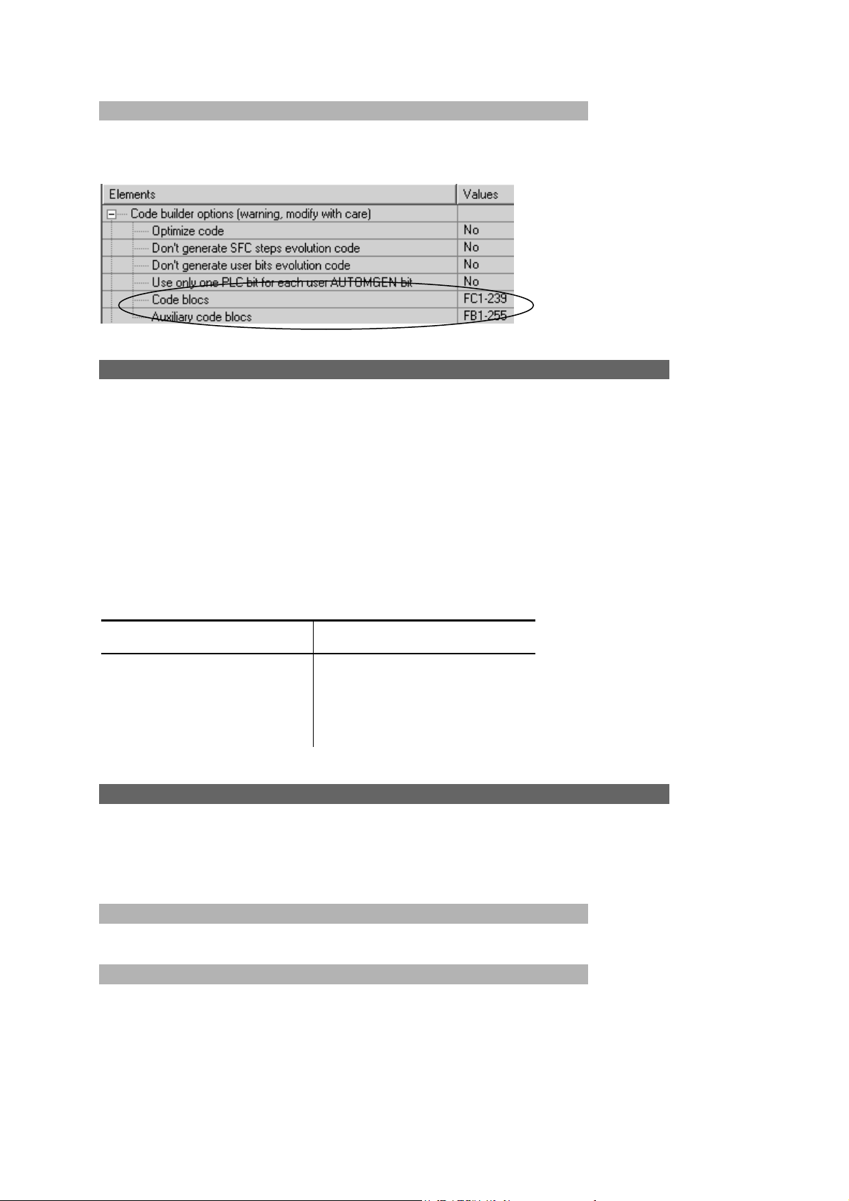
Post-processor manual
Selecting program blocks to use
Blocks FC1 to FC 239 and FB 1 to FB 255 are used by default. Two configuration
elements are used to select other blocks.
Associating code written on a sheet to a program block
When writing low level literal code or machine code on an organizational chart on a
« Task » type sheet, associate the code to a STEP7 block.
The task number determines the block type and number.
The generated code for that sheet must take into account the block type and the
instructions used in that block type (The set of instructions for blocks OB and PB is
limited).
The table below provides the correspondence between the task number and the
STEP7 block.
Task number STEP7 block
0 to 255 OB 0 to OB 255
256 to 511 FC 0 to FC 255
512 to 767 FB 0 to FB 255
Specific examples
These examples are in the directory « <AUTOMGEN installation
directory> /Examples/Post-processors/S7300 ».The files have the same names as
the titles of the following chapters.
Calling up a STEP7 block
Example of calling up STEP7 function blocks
Using an OB block
Example of an association of code written on a sheet to an OB block.
AUTOMGEN
7
68 (C)opyright 2004 IRAI
Page 69

Post-processor manual
Post-processor OMRON
This post-processor is used to program OMRON processors .
Select PLC model
Tht item « Configuration / Post-processor / OMRON / System / Hardware
configuration » must be used to select PLC model.
Communication module
Setting communication module parameters
Transferring applications to the CX-PROGRAMMER software
- at the end of compiling in AUTOMGEN, double click on the « Generated files /
OMRON / step 2 » element,
AUTOMGEN
7
69 (C)opyright 2004 IRAI
Page 70

Post-processor manual
- select all the lines,
- select the « Copy » command in the « Edit » menu
- in CX-PROGRAMMER, create a new application, display the program area in
mnemonics format,
AUTOMGEN
7
70 (C)opyright 2004 IRAI
Page 71

Post-processor manual
- select the program area and then paste the lines,
You can upload the application in the processor starting from CX-PROGRAMMER
then return to AUTOMGEN to tune the program in connected mode (remember to
disconnect CX-PROGRAMMER from the processor to be able to communicate from
AUTOMGEN).
7
AUTOMGEN
71 (C)opyright 2004 IRAI
Page 72

Post-processor manual
Specific syntax
The following syntax is used to set the value of a data word.
$DMn=value
« n » is the word number;
« value » is a 16 bit value expressed by default in decimal or hexadecimal if
preceded by the character 'H'.
Example:
$DM10=50
$DM100=HA000
Associating code written on a sheet to a program block
When writing low level literal code or machine code on an organizational chart on a
« Task » type sheet, associate the code to a interrupt task. The task number is
equivalent to the stop number.
Specific example
This example is in the directory « <AUTOMGEN installation
directory> /Examples/Post-processors/S7200 ».The file has the same name as the
title of the following chapter.
Interrupt task
Example of calling up a interrupt task
AUTOMGEN
7
72 (C)opyright 2004 IRAI
Page 73

Post-processor manual
Post-processor ALSPA
This post-processor is used to program CEGELEC ALSPA C50 and C100
processors.
Communication module
Setting communication module parameters
AUTOMGEN
7
73 (C)opyright 2004 IRAI
Page 74

Post-processor manual
Post-processor ZELIO
This post-processor is used to program SECHNEIDER ZELIO modules.
Communication module
Setting communication module parameters
AUTOMGEN
7
74 (C)opyright 2004 IRAI
Page 75
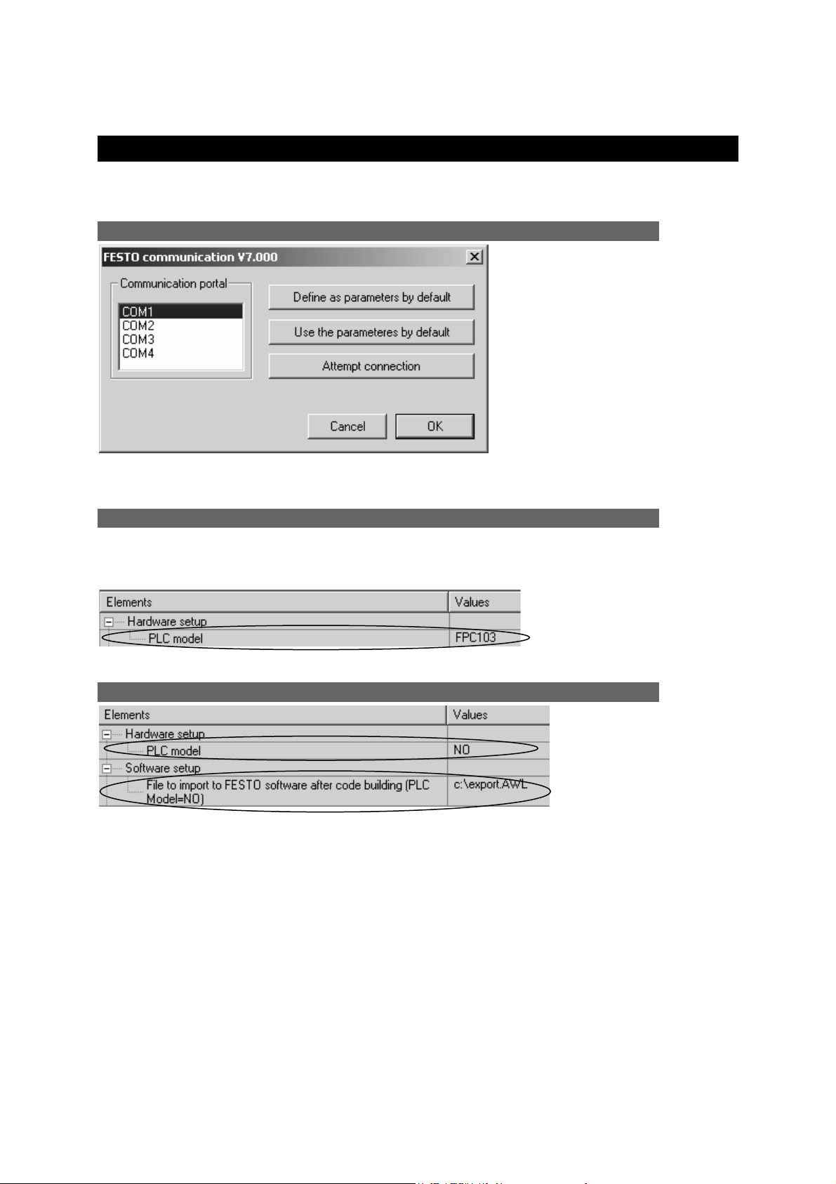
Post-processor manual
Post-processor FESTO
This post-processor is used to program FPC 101, FPC 103 and FEC FESTO
processors .
Communication module
Setting communication module parameters
Generating a binary file
Binary files can be directly generated and downloaded in FPC 101 and FPC 103
processors. The FST FESTO software workgroup in DOS or WINDOWS is necessary
for FEC processors.
Selecting a CPU type (direct generation of a binary file)
Importation in a FESTO software workgroup
Generation of an AWL file compatible with FESTO workgroups
If you use the FST FESTO software workgroup in DOS, create the AWL file in this
software.
If you use the FST FESTO software in WINDOWS, open the generated file in
AUTOMGEN by double clicking on « Generated files / FESTO / Pass 2 », select all
the files, use the command « Copy » in the « Edit » menu and then the command
« Paste » in the FESTO software to retrieve the generated code.
Transfer the program to the processor with the FESTO software.
AUTOMGEN
7
75 (C)opyright 2004 IRAI
Page 76

Post-processor manual
Then you can connect to AUTOMGEN (after you have disconnected the FESTO
software) by using the « Only connect ».connection mode.
AUTOMGEN
7
76 (C)opyright 2004 IRAI
Page 77

Post-processor manual
Post-processor ALLEN-BRADLEY
This post-processor is used to program ROCKWELL SLC processors. ROCKWELL
RSLogix 500 V5 software or higher is required.
The RSLogix 500 STARTER version cannot be used to import
files generated by AUTOMGEN.
Communication module
Setting communication module parameters
Transferring programs to ROCKWELL RS-Logix 500 Software
In the element below you create a file used for exchange between AUTOMGEN and
RSLogix 500. This file will be generated after compilation in AUTOMGEN
Generating an .SLC file compatible with RSLogix 500
AUTOMGEN
7
77 (C)opyright 2004 IRAI
Page 78

Post-processor manual
Launch RSLogix500, then open the .SLC file generated by AUTOMGEN.
Transfer the program to the processor using the RSLogix 500 software. After
disconnecting the RSLogix 500 software from the processor, you can tune it from
AUTOMGEN in connected mode.
AUTOMGEN
7
78 (C)opyright 2004 IRAI
Page 79

Post-processor manual
Post-processor TWIDO
This post-processor is used to program SCHNEIDER TWIDO processors.
Processor configuration selection
The « Configuration / Post-processor / TWIDO / System / Hardware configuration »
element on the browser is used to select the type of processor.
The « .TWD » file is a configuration file which must be generated with the
SCHNEIDER TWIDOSOFT software workgroup. The sub-directory « TWIDO » in the
AUTOMGEN installation directory contains the configuration files for various types of
TWIDO processors.
Communication module
AUTOMGEN
7
79 (C)opyright 2004 IRAI
Page 80

Post-processor manual
Post-processor MITSUBISHI
This post-processor is used to program FX series MITSUBISHI processors. The code
generated by AUTOMGEN can be directly sent to FX series MITSUBISHI processors
or imported in MITSUBISHI FX-WIN or GX-DEVELOPPER software.
Selecting the type of processor
« Configuration / Post-processor / MITSUBISHI / System / Hardware configuration»
on the browser is used to select the type of PLC.
Communication module
Setting the communication module
Transferring programs to MITSUBISHI FX-WIN software
Select FXWIN in the element below.
7
AUTOMGEN
80 (C)opyright 2004 IRAI
Page 81
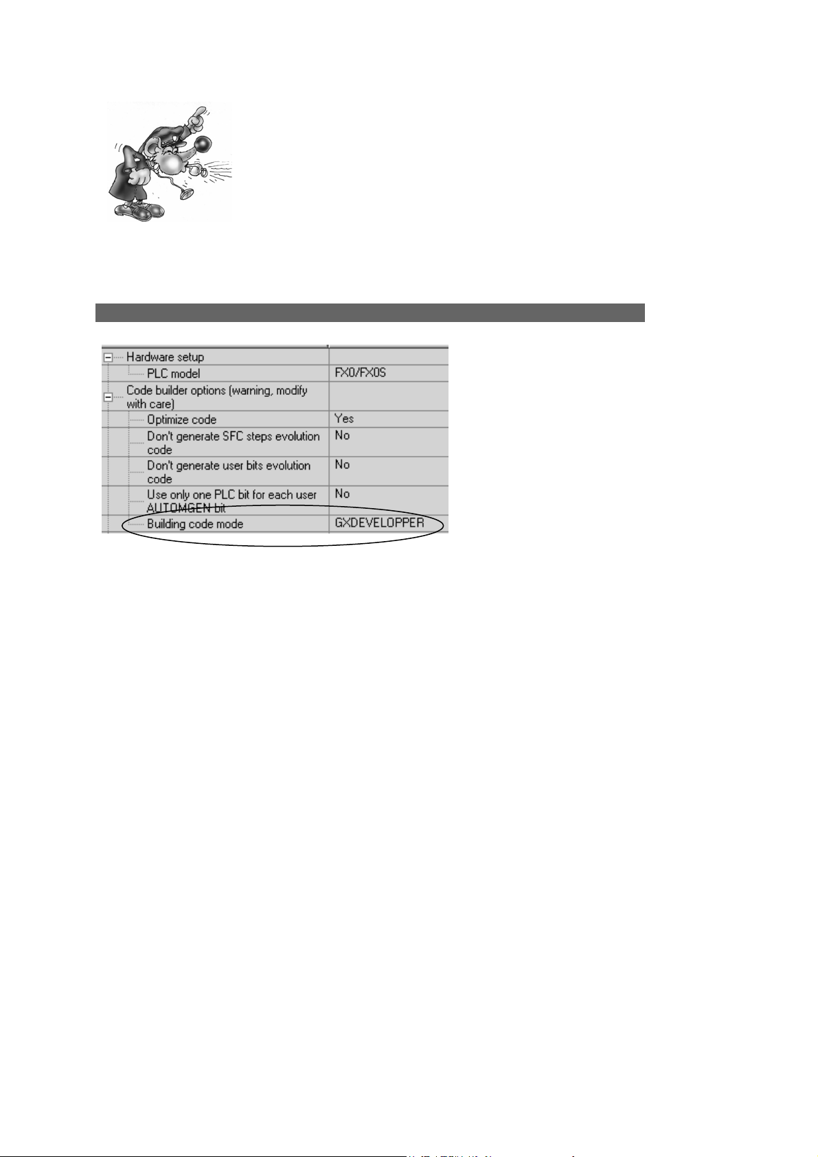
Post-processor manual
The English version of FXWIN must be used. Importation has
been validated for the 3.20 version of FX-WIN.
After compilation in AUTOMGEN, create a project in FX-WIN. Open the program in
editing, instruction list and select « Enter » in the « Edit » menu.
Transferring programs to MITSUBISHI GX-DEVELOPPER software
Select GXDEVELOPPER in the element below.
Launch the executable « A7TOGX.EXE » in the AUTOMGEN installation directory.
After launching it, an icon « A7 → GX » appears in the WINDOWS icon bar.
After compiling AUTOMGEN, create a project in GX-DEVELOPPER. Open the
program in editing, instruction list. Press the two SHIFT keys or the LEFT SHIFT key
and the F11 key at the same time for one second. The program will be transferred to
GX-DEVELOPPER.
To uninstall « A7TOGX » click on the icon with the right side of the mouse. You can
leave « A7TOGX » installed as long as it is necessary, so you do not need to install
and uninstall it every time you want to import an application in GX-DEVELOPPER.
AUTOMGEN
7
81 (C)opyright 2004 IRAI
Page 82

Post-processor manual
Post-processor MITSUBISHI-Q
This post-processor is used to program Q series MITSUBISHI processors. The code
generated by AUTOMGEN must be imported in MITSUBISHI GX-DEVELOPPER
software.
Communication module
Setting the communication module
Transferring programs to MITSUBISHI GX-DEVELOPPER software
Launch the executable « A7TOGX.EXE » in the AUTOMGEN installation directory.
After launching it, an icon « A7 → GX » appears in the WINDOWS icon bar.
After compiling AUTOMGEN, create a project in GX-DEVELOPPER. Open the
program in editing, instruction list. Press the two SHIFT keys or the LEFT SHIFT key
and the F11 key at the same time for one second. The program will be transferred to
GX-DEVELOPPER.
To uninstall « A7TOGX » click on the icon with the right side of the mouse. You can
leave « A7TOGX » installed as long as it is necessary, so you do not need to install
and uninstall it every time you want to import an application in GX-DEVELOPPER.
AUTOMGEN
7
82 (C)opyright 2004 IRAI
Page 83

Post-processor manual
Post-processor GEM
This post-processor is used to program GEM PLCs.
Communication module
Setting the communication module
For setting the communication module parameters, launch the ESPLINK.EXE file into
the AUTOMGEN installation directory and select the “Edit / Setup Comms ...” menu.
AUTOMGEN
7
83 (C)opyright 2004 IRAI
 Loading...