

Page 1

- USA
OWNER'S MANUAL
30 lb. DR LAUNDRY DRYER
Shown with manual
double timer
control system
Technical specifications
Installation instructions
Operating instructions
Maintenance
DR30
IPSO - USA
3101 South Haven Highway 77, Suite A
Panama City, FL, 32405
Phone: (850)271-8486
THIS MANUAL MUST BE GIVEN TO THE EQUIPMENT OWNER
MAN DR2030 (ECN5652) 9/99 D0566
Page 2
IMPORTANT NOTICES—PLEASE READ
For optimum efficiency and safety, we recommend that you read the manual before operating the equipment. Store
this manual in a file or binder and keep for future reference.
WARNING: Purchaser must post the following notice in a prominent location:
WARNING: For your safety, the information in this manual must be followed to minimize
the risk of fire or explosion or to prevent property damage, personal injury or death.
- Do not store or use gasoline or other flammable vapors or liquids in the vicinity of this or
any other appliance.
- WHAT TO DO IF YOU SMELL GAS
• Do not try to light any appliance.
• Do not touch any electrical switch; do not use any phone in your building.
• Clear the room, building or area of all occupants.
• Immediately call your gas supplier from a neighbor's phone. Follow the gas
supplier's instructions.
• If you cannot reach your gas supplier, call the fire department.
Installation and service must be performed by a qualified installer, service agency or the
gas supplier.
WARNING: In the event the user smells gas odor, instructions on what to do must be posted in a
prominent location. This information can be obtained from the local gas supplier.
WARNING: Wear safety shoes to prevent injuries.
WARNING: Purchaser must post the following notice in a prominent location:
FOR YOUR SAFETY
Do not store or use gasoline or other flammable vapors
and liquids in the vicinity of this or any other appliance.
WARNING: A clothes dryer produces combustible lint and should be exhausted outside the
building. The dryer and the area around the dryer should be kept free of lint.
WARNING: Be safe, before servicing machine, the main power should be shut off.
Page 2
Page 3

ATTENTION: L’ACHETEUR DOIT PLACER L’AVERTISSEMENT
SUIVANT DANS UN ENDROIT CLAIR ET VISIBLE:
AVERTISSEMENT. Assurez-vous de bien
suivre les instructions donnees dans cette
notice pour reduire au minimum le risque
d’incendie ou d’explosion ou pour eviter tuot
dommage materiel, toute blessure ou la mort.
__ Ne pas entreposer ni utiliser d’essence ni
d’autres vapeurs ou liquides inflammables dans
le voisinage de cet appareil ou de tout autre
apparell.
__ QUE FAIRE SI VOUS SENTEZ UNE
ODEUR DE GAZ:
• Ne pas tenter d’allumer d’apparell.
• Ne touchez a aucun interrupteur. Ne pas
vous servir des telephones se trouvant dans
le batiment ou vous vous trouvez.
• Evacuez la piece, le batiment ou la zone.
• Appelez immediatement votre fournisseur de
gaz depuis un voisin. Suivez les instructions
du fournisseur.
• Si vous ne pouvez rejoindre le fournisseur
de gaz, appelez le service des incendies.
__ l’installation et l’entretien doivent etre assures
par un installateur ou un service d’entretien
qualifie ou par le fournisseur de gaz.
ATTENTION: L’ACHETEUR DOIT PLACER L’AVERTISSEMENT
SUIVANT DANS UN ENDROIT CLAIR ET VISIBLE:
POUR VOTRE SECURITE
Ne pas entreposer ni utiliser d’ essence
ni d’autres vapeurs ou liquides
inflammables dans le voisinage de cet
appareil ou de tout autre appareil.
Page 3
Page 4
WARNING: To avoid fire hazard, do not dry articles containing foam rubber or similar texture materials.
Do not put into this dryer flammable items such as baby bed mattresses, throw rugs, undergarments
(brassieres, etc.) and other items which use rubber as padding or backing. Rubber easily oxidizes causing
excessive heat and possible fire. These items should be air dried.
WARNING: Synthetic solvent fumes from drycleaning machines create acids when drawn through the
dryer. These fumes cause rusting of painted parts, pitting of bright or plated parts, and completely
removes the zinc from galvanized parts, such as the tumbler basket. If drycleaning machines are in the
same area as the tumbler, the tumbler's make-up air must come from a source free of solvent fumes.
WARNING: Do not operate without guards in place.
WARNING: Check the lint trap often and clean as needed but at least a minimum of once per day.
WARNING: Alterations to equipment may not be carried out without consulting with the factory and
only by a qualified engineer or technician. Only Manufacturer’s parts may be used.
WARNING: Remove clothes from dryer as soon as it stops. This keeps wrinkles from setting in and
reduces the possibility of spontaneous combustion.
WARNING: Be Safe - shut main electrical power and gas supply off externally before attempting
service.
WARNING: Never use drycleaning solvents, gasoline, kerosene, or other flammable liquids in the dryer.
FIRE AND EXPLOSION WILL OCCUR. NEVER PUT FABRICS TREATED WITH THESE
LIQUIDS INTO THE DRYER. NEVER USE THESE LIQUIDS NEAR THE DRYER..
WARNING: Do not place items exposed to cooking oils in your dryer. Items contaminated
with cooking oils may contribute to a chemical reaction that could cause a load to catch fire.
WARNING: Never let children play near or operate the dryer. Serious injury could occur if a child
should crawl inside and the dryer is turned on.
WARNING: Never tumble fiberglass materials in the dryer unless the labels say they are machine
dryable. Glass fibers break and can remain in the dryer. These fibers cause skin irritation if they
become mixed with other fabrics.
WARNING: Before operating gas ignition system - purge air from natural gas or propane gas lines
per manufacturer’s instructions.
WARNING: To reduce the risk of electric shock, disconnect this appliance from the power supply
before attempting any user maintenance other than cleaning the lint trap. Turning the controls to the
OFF position does not disconnect this appliance from the power supply.
Page 4
Page 5

IPSO DRYER WARRANTY
IPSO warrants all new equipment (and the original parts thereof) to be free from defects in material or workmanship for
a period of two (2) years from the date of sale thereof to an original purchaser for use, except as hereinafter provided. With
respect to non-durable parts normally requiring replacement in less than two (2) years due to normal wear and tear, and with
respect to all new repair or replacement parts for IPSO equipment for which the two (2) year warranty period has expired,
or for all new repair or replacement parts for equipment other than IPSO equipment, the warranty period is limited to ninety
(90) days from date of sale. The warranty period on each new replacement part furnished by IPSO in fulfillment of the
warranty on new equipment or parts shall be for the unexpired portion of the original warranty period on the part replaced.
With respect to electric motors, coin meters and other accessories furnished with the new equipment, but not manufactured
by IPSO, the warranty is limited to that provided by the respective manufacturer.
IPSO’s total liability arising out of the manufacture and sale of new equipment and parts, whether under the warranty or
caused by IPSO’s negligence or otherwise, shall be limited to IPSO-USA repairing or replacing, at its option, any defective
equipment or part returned f.o.b. IPSO’s factory, transportation prepaid, within the applicable warranty period and found by
IPSO to have been defective, and in no event shall IPSO be liable for damages of any kind, whether for any injury to persons
or property or for any special or consequential damages. The liability of IPSO does not include furnishing (or paying for)
any labor such as that required to service, remove or install; to diagnose troubles; to adjust, remove or replace defective
equipment or a part; nor does it include any responsibility for transportation expense which is involved therein.
The warranty of IPSO is contingent upon installation and use of its equipment under normal operating conditions. The
warranty is void on equipment or parts; that have been subjected to misuse, accident, or negligent damage; operated under
loads, pressures, speeds, electrical connections, plumbing, or conditions other than those specified by IPSO; operated or
repaired with other than genuine IPSO replacement parts; damaged by fire, flood, vandalism, or such other causes beyond
the control of IPSO; altered or repaired in any way that effects the reliability or detracts from its performance, or; which
have had the identification plate, or serial number, altered, defaced, or removed.
No defective equipment or part may be returned to IPSO for repair or replacement without prior written authorization from
IPSO. Charges for unauthorized repairs will not be accepted or paid by IPSO.
IPSO MAKES NO OTHER EXPRESSED OR IMPLIED WARRANTY, STATUTORY OR OTHERWISE,
CONCERNING THE EQUIPMENT OR PARTS INCLUDING, WITHOUT LIMITATION, A WARRANTY OF
FITNESS FOR A PARTICULAR PURPOSE, OR A WARRANTY OF MERCHANTABILITY. THE
WARRANTIES GIVEN ABOVE ARE EXPRESSLY IN LIEU OF ALL OTHER WARRANTIES, EXPRESSED
OR IMPLIED. IPSO NEITHER ASSUMES, NOR AUTHORIZES ANY PERSON TO ASSUME FOR IT, ANY
OTHER WARRANTY OR LIABILITY IN C ON NE C TI ON WITH THE MANUFACTURE, USE OR SALE OF ITS
EQUIPMENT OR PARTS.
For warranty service, contact the distributor from whom the IPSO equipment or part was purchased. If the distributor cannot
be reached, contact IPSO.
IDENTIFICATION NAMEPLATE
The identification nameplate is located on the rear wall of the dryer. It contains the dryer serial number, product number, model
number, electrical specifications and other important data that may be needed when servicing and ordering parts, wiring diagrams,
etc. Do not remove this nameplate.
Page 5
Page 6

Contents
Safety Instructions .............................................................................. 2-4
Cissell Dryer Warranty ....................................................................... 5
Table of Contents ................................................................................ 6
Symbols ............................................................................................... 7
Unpacking / General Installation ....................................................... 8-9
Technical Data and Dimensions......................................................... 10-11
Electric Connections ........................................................................... 12
Gas Connections ................................................................................. 13
Gas Piping Installation ....................................................................... 14-15
Gas service Installation Instructions ................................................ 16
Gas Pipe Size Chart ............................................................................ 17
Dryer Installation with Multiple Exhaust ...........................................18-19
Dryer Make-Up Air Requirements ...................................................... 20
Dryer Installation with Separate Exhaust ......................................... 21
Exhaust and Venting ........................................................................... 22
Rules for Safe Operation of Dryer ..................................................... 23
Direct-Spark Ignition Operation......................................................... 24-25
General Maintenance ..........................................................................26-27
Operating Instruction for Double Timer ........................................... 28
PARTS .................................................................................................. 29-43
Front View ................................29
Front Panel Assembly .............31
Wire Box Assembly .................33
Lint Door Assembly ................ 35
Rear View .................................37
Basket Bearings/Sheave Assy 39
Idler Assembly .........................41
Gas Heating Unit Assembly ...43
Control Door Assembly ..........30
Thermostat Assembly ............. 32
Door Assembly ........................34
Basket & Spider Assembly .....36
Air Switch Assembly............... 38
Motor & Fan Assembly ........... 40
Rear Control Panel Assembly 42
Page 6
Page 7
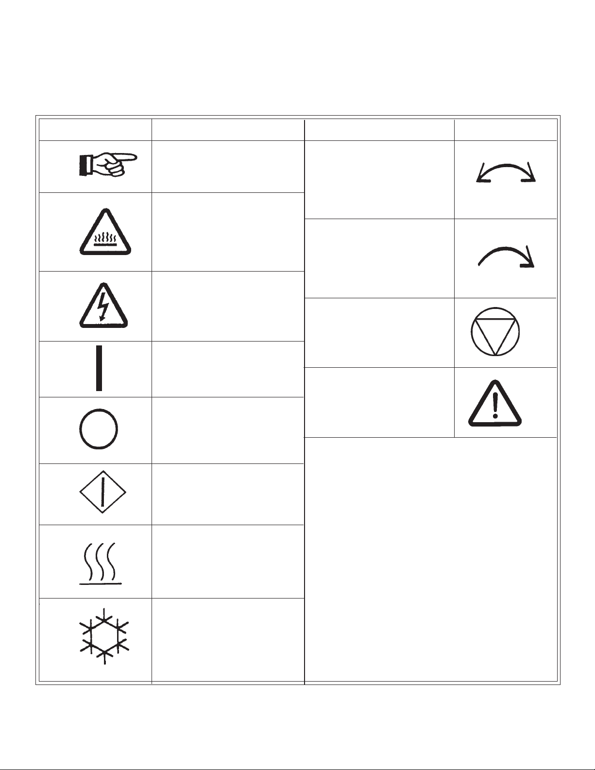
SYMBOLS
The following symbols are used in this manual and/or on the machine.
Symbol
Description
NOTE!
Hot! Do Not Touch
Heiß! Nicht Beruhren
Haute temperature! Ne pas toucher
Caliente! no tocar
dangerous voltage
tension dangereuse
Gefährliche elektrische
Spannung
tension peligrosa
On
Marche
Ein
Conectado
Off
Arrêt
Aus
Desconectado
Symbol
Rotation in two directions
Rotation dans les deux sens
Drehbewigung in zwei
Richtungen
Movimiento rotativo en los
dos sentidos
Direction of rotation
Sens de mouvement continu
De rotation Drehbewegung
in Pfeilrichtung movimiento
Giratorio o rotatorio en el
sentido de la flecha
End of Cycle
Caution
Attention
Achtung
Atencion; precaucion
Start
Demarrage
Start
Arranque de un movimiento
Emission of heat in general
Emission de chaleur en
general
Warmeabgabe allgemein
Emisión de calor
Cooling
Refroidissement
Kühlen
Enfriamiento
Page 7
Page 8

Unpacking/General Installation (All Dryers)
UNPACKING
GENERAL
INSTALLATION
(ALL DRYERS)
Upon arrival of the equipment, any damage in shipment should be
reported to the carrier immediately.
Upon locating permanent location of a unit, care should be
taken in movement and placement of equipment.
See outline clearance diagrams for correct dimensions.
Remove all packing material such as: tape, manuals, skid,
etc
Leveling: Use spirit level on top of dryer. Adjust leveling
bolts on dryer (see adjustable leveling bolts in maintenance
section).
Check voltage and amperes on rating plate before
installing the dryer.
The construction of the dryers permit installation side-by-side to save
space or to provide a wall arrangement. Position dryer for the least
amount of exhaust piping and elbows, and allow free access to the
rear of dryer for future servicing of belts, pulleys and motors. The
installation clearance from all combustable material is 0" ceiling
clearance for the first 4" (102 mm)from the front of the dryer. After
the first 4" (102 mm), the ceiling clearance required is 6" (153 mm).
The rear clearance required is 0", and the side clearance is 1"
(26 mm).
Before operating dryer, open basket door and remove
blocking between front panel and basket. Read the
instruction tags, owner’s manual, warnings, etc.
IMPORTANT
Opening the clothes loading door deactivates the door switch
to shut off the motors, fan, gas, steam, or electric element. To
restart the dryer, close the door and press in the push to start
button.
IMPORTANT
This dryer is designed for a capacity maximum load.
Overloading it will result in long drying times and damp spots
on some clothes.
IMPORTANT
Maximum operating efficiency is dependent upon proper air
circulation. The lint screen must be kept clean daily to ensure
proper air circulation throughout the dryer.
IMPORTANT
Provide adequate clearance for air opening into the combustion
chamber.
Page 8
Page 9

Unpacking/General Installation (All Dryers)
GENERAL
INFORMATION
DRYER
“COOL-DOWN”
CYCLE
The dryer is so designed that when an operator opens the dryer
door, the basket and exhaust fan stop. You can expect fast drying
from a laundry dryer. Hot, dry air is properly and effectively
moved through the basket and exhausted through a lint trap to the
atmosphere. The dryer comes equipped with an inclined selfcleaning lint screen. In this system, lint accumulates on the
underside of the screen until a blanket of lint will fall from the
screen to the bottom of the dryer cabinet, and should be removed
daily or as required, to prevent an over-accumulation.
IMPORTANT
Provide adequate clearance for air openings into the combustion
chamber.
Permanent press, durable press and other modern day
fabrics require the care that your dryers now provide. At the end of
the drying cycle, a timed “Cool-Down” control automatically takes
over and continues the rotation of the fan and basket without heat
until the garment load reaches a safe cool temperature. This
function is performed at the end of each drying cycle.
REPLACEMENT
PARTS
Replacement parts for this dryer are available from your distributor
or by contracting the factory at the address or phone number printed
on the cover page of this manual.
Page 9
Page 10
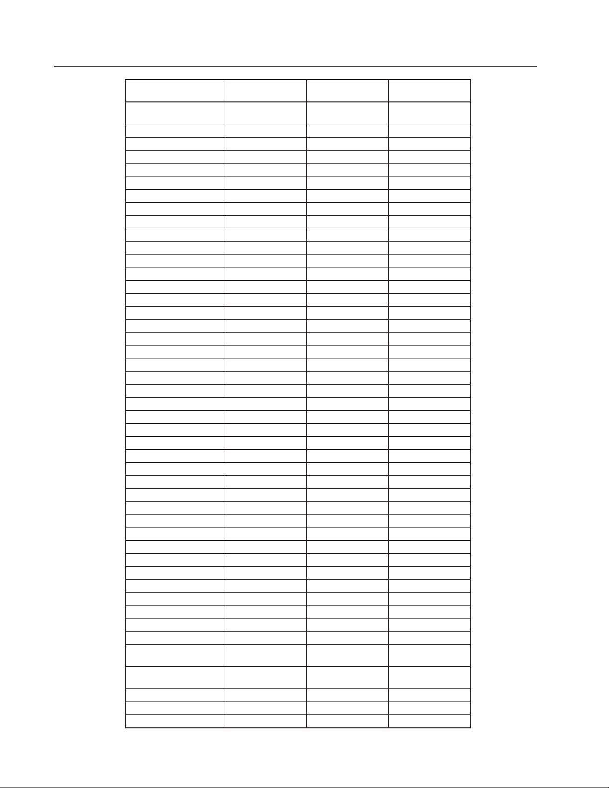
30 lb. Dryer Dimensions - Standard Gas, Steam and Electric Heated
snoitacificepSerusaeM.S.U
yticapaC
)neniLyrD(
.sbl03gk6.31
cirteM
erusaeM
teksaB
retemaiDsehcni03mm048
htpeDsehcni
emuloVtf9.11
92mm518
3
retil533
tenibaC
thgieHsehcni27mm8281
htdiWsehcni33mm838
htpeDsehcni61/5-34mm0011
gninepOrooD
retemaiDsehcni8/5-22m
m575
thgiehgnidaoLsehcni2/1-13mm008
erutarepmeT
0
muminiM001
mumixaM581
F83oC
0
F580C
rotoM
gnisrever-noN.P.H2/1Wk73.0
murD-gnisreveR.P.H2/1Wk73.0
naF.P.H3/1Wk52.0
tsuahxE
3
etaRwolFmfc526m3601
h/
retemaiDsehcni8mm302
sreyrDcirtcelE-.nnoCcirtcelE
gnisreveR-noNgnisreveR
V802HP3-06A76A86
V042/022HP3-06/05A06/
55A06/55
V514/083HP3-05A73/43A63/33
V084HP3-06A03A13
sreyrDsaG,maetS-.nnoCcirtcelE
/511HP1-06/05A4.9A8.4
V042-802
gnisreveR-noNgnisreveR
V514/083HP3-06/05A2.1A1.1
V084HP3-06/05A9.0A9.0
rewoP
cirtcelEWk5.22Wk5.22
saGh/utB000,011h/lack0
27,72
maetSP.H.B5.4h/lack000,83
noitcennocmaetS
telnI"4/302ND
teltuO"2/151ND
noitcennoCsaG
noitcennoCsaG"2/151ND
sserPsaG"21-"5bm03-21
eru
gnippihS
snoisnemiD
)DxWxH(
84X63X87
sehcni
419X1891
mm9121X
thgieW
teN.sbl705gk032
ssorG.sbl2
45gk642
Page 10
Page 11
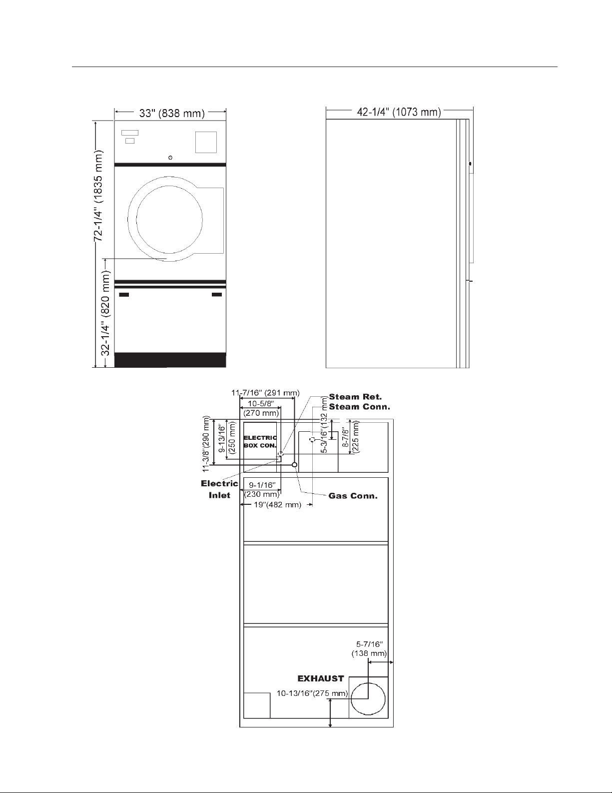
DR30 Dryer Dimensions - Gas
(Illustration)
Page 11
Page 12
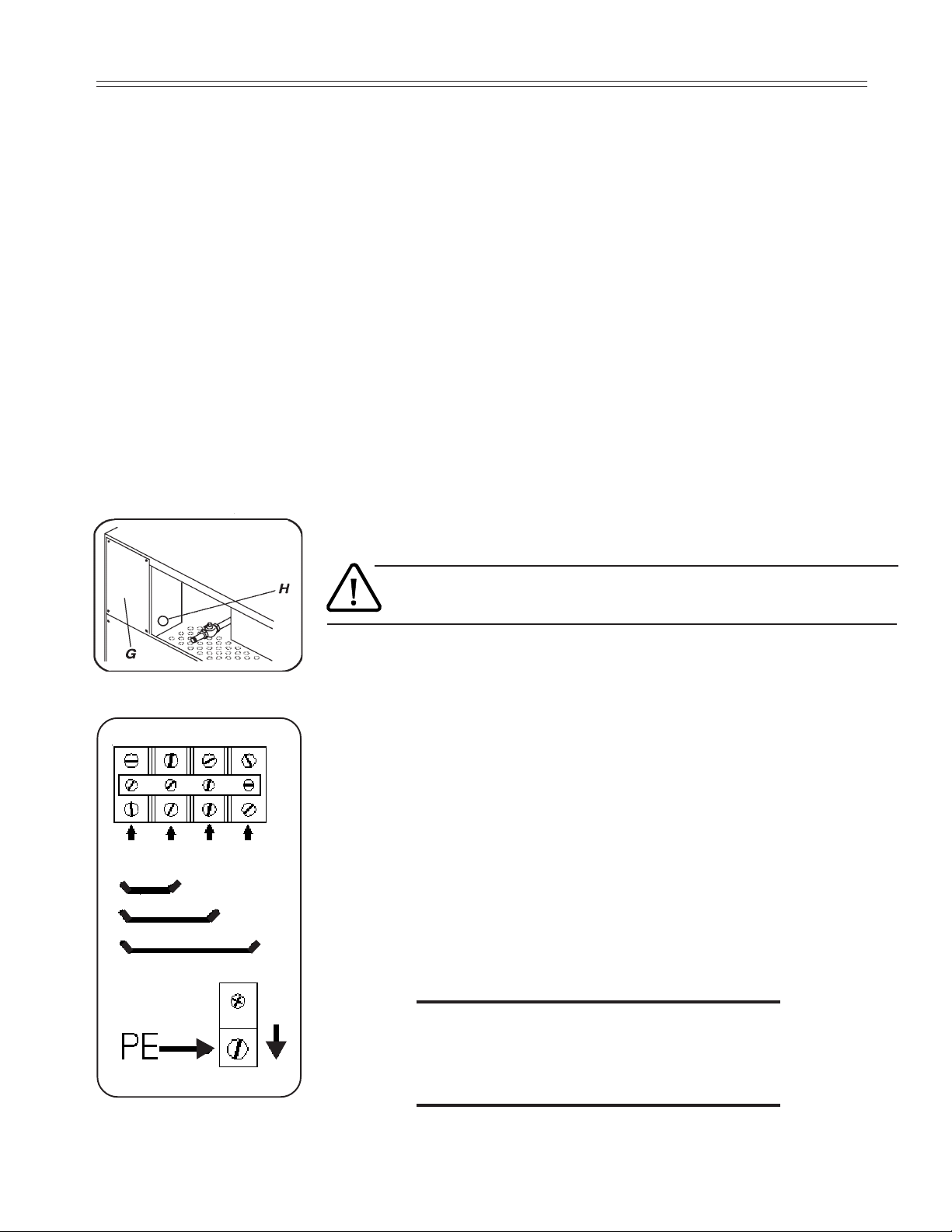
Electric connection
Dryers must be electrically grounded by a separate #14 or larger green wire from the grounding terminal
within the Service Connection Box, to a cold water pipe. In all cases, the grounding method must comply
with local electrical code requirements; or in the absence of local codes, with the National Electrical
Code, ANSI/NFPA 70 or the Canadian Electrical Code, CA C22.1.
See wiring diagram furnished with dryer. Do not change wiring without consulting the factory, as you
may void the factory warranty. DO NOT CONNECT THE DRYER TO ANY VOLTAGE OR
CURRENT OTHER THAN THAT SPECIFIED ON THE DRYER RATING PLATE. (Wiring diagram
is located on rear wall of dryer.)
All panels must be in position before operation of dryer.
The connection needs to be made in the wiring box at the back. Remove the
coverplate (G) in order to reach the connection clamps.
The connection cable needs to be brought in through the opening (H) in the side of
the wiring box.
L1
L2
L3
N
115 and 208-240 V - 1 ph
208-240 and 480 V - 3 ph
380-415V - 3 ph
It is necessary to ground the dryer for your personal safety and to ensure a good
operation.
115 and 208-240 V - 1 ph
The mains wires (Ll) and (L2) should be connected to the 2 left clamps and the
yellow/green grounding wire (PE) should be connected to the grounding clamp.
208-240 and 480 V - 3 ph
The 3 mains wires (L1), (L2) and (L3) should be connected to the 3 left clamps and
the yellow/green grounding wire (PE) should be connected to the grounding
clamp.
380-415V - 3 ph
The 3 mains wires (L1), (L2) and (L3) should be connected to the 3 left clamps,
the blue neutral (N) should be connected to the right clamp and the yellow/green
grounding wire (PE) should be connected to the grounding clamp.
«Attention. Lors des opérations d’entretien
des commandes, ètiqueter tous les fils avant
de les dèconnecter. Toute erreur de câblage
peut être une source de danger et de panne»
Page 12
Page 13

Gas connection
The gas supply pipe should be connected to the gas tap (I), which is on the right next
to the wiring box on the back.
It is important to have the connections done by a qualified technician, in order to
ensure that the installation is in accordance with the prevailing standards and
instructions.
The dryer should be connected to the type of gas indicated on the serial plate.
The use of too small gas pipes can result in insufficient gas supply, which can lead
to slow heat-up and poor drying quality.
I
When the dryer is used in combination with a weighing platform, the gas supply pipe
has to be made of flexible material to allow the weighing system to keep moving
freely.
Test all connections for possible leaks by means of a soap solution, but
never with a flame.
It is important to work with the right gas pressure (see technical remarks) in order to
obtain a good ignition, heating and consequently a good operation in general.
After the gas supply has been connected, the gas tap in the dryer should be turned on
(clockwise).
Electrical Controls Service
Caution: Label all wires prior to disconnection when servicing controls. Wiring errors can
cause improper and dangerous operation.
Verify proper operation after servicing.
Page 13
Page 14

Gas Piping Installation
GAS PIPING
INSTALLATION
1. The installation must conform with local codes, or in the
absence of local codes with the National Fuel Gas Code,
ANSI Z223.1 or the CAN/CGA-B149, Installation Codes.
2. Check Identification Nameplate for type of gas for
dryer.
3. Check the altitude of dryer.
4. Check with utilities company for proper gas
pressure and gas supply line.
5. Natural Gas Only—Check the gas pressure inlet
supply to dryer, 11 inches water column (27.4 mbar)
maximum.
Manifold Pressure—3.5 inches water column (8.8 mbar)
pressure.
6. L.P. Gas Only—Manifold pressure—13 inches water column
(32.4 mbar) maximum.
CAUTION: Low gas pressure and intermittent gas will cause
gas ignition problems and inadequate drying of laundry.
Page 14
Page 15
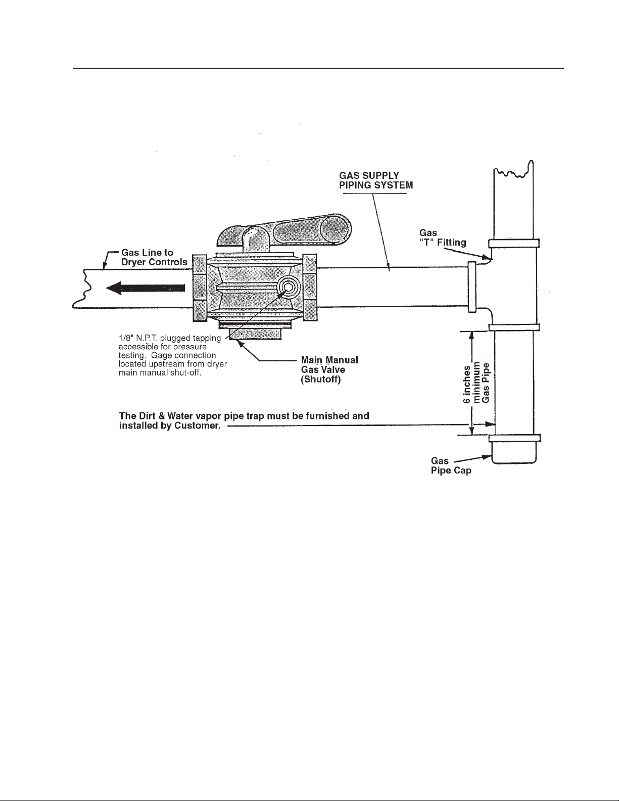
Gas Piping Installation (Illustrations)
The dryer and its individual shutoff valve must be disconnected from the gas supply piping system
during any pressure testing of that system at test pressures in excess of 1/2 psi (.04 bar).
The dryer must be isolated from the gas supply piping system by closing its individual manual shutoff
valve during any pressure testing of the gas supply piping system at test pressures equal to or less
than 1/2 psi (.04 bar).
Page 15
Page 16
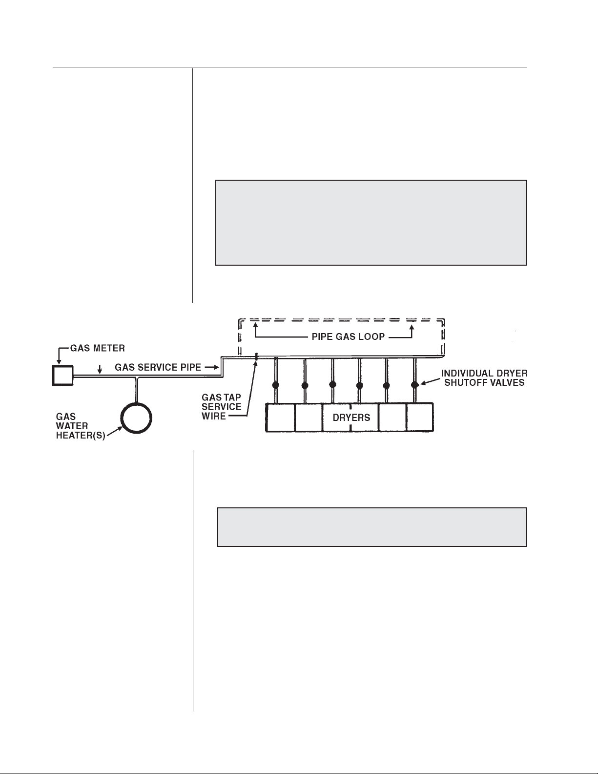
Gas Service Installation Instructions
GAS SERVICE
INSTALLATION
INSTRUCTIONS
The size of the gas service pipe is dependant upon many variables,
such as tees, lengths, etc. Specific pipe size should be obtained from
the gas supplier. Refer to the “Gas Pipe Size” chart in this manual for
general gas pipe size information.
CAUTION: Gas loop piping must be installed as illustrated
to maintain equal gas pressure for all dryers connected to a
single gas service
Other gas-using appliances should be connected
upstream from the loop.
GAS PRESSURE
REGULATOR FOR
LIQUIFIED
PETROLEUM GASES
WARNING:
LIQUIFIED PETROLEUM GASES ONLY !
A gas pressure regulator for liquified petroleum gases is not
furnished on gas heated clothes dryers. This regulator is normally
furnished by the installer. In accordance with American Gas
Association (AGA) standards, a gas pressure regulator, when
installed indoors, must be equipped with a vent limiter or a vent line
must be installed from the gas pressure regulator vent to the outdoors.
Page 16
Page 17
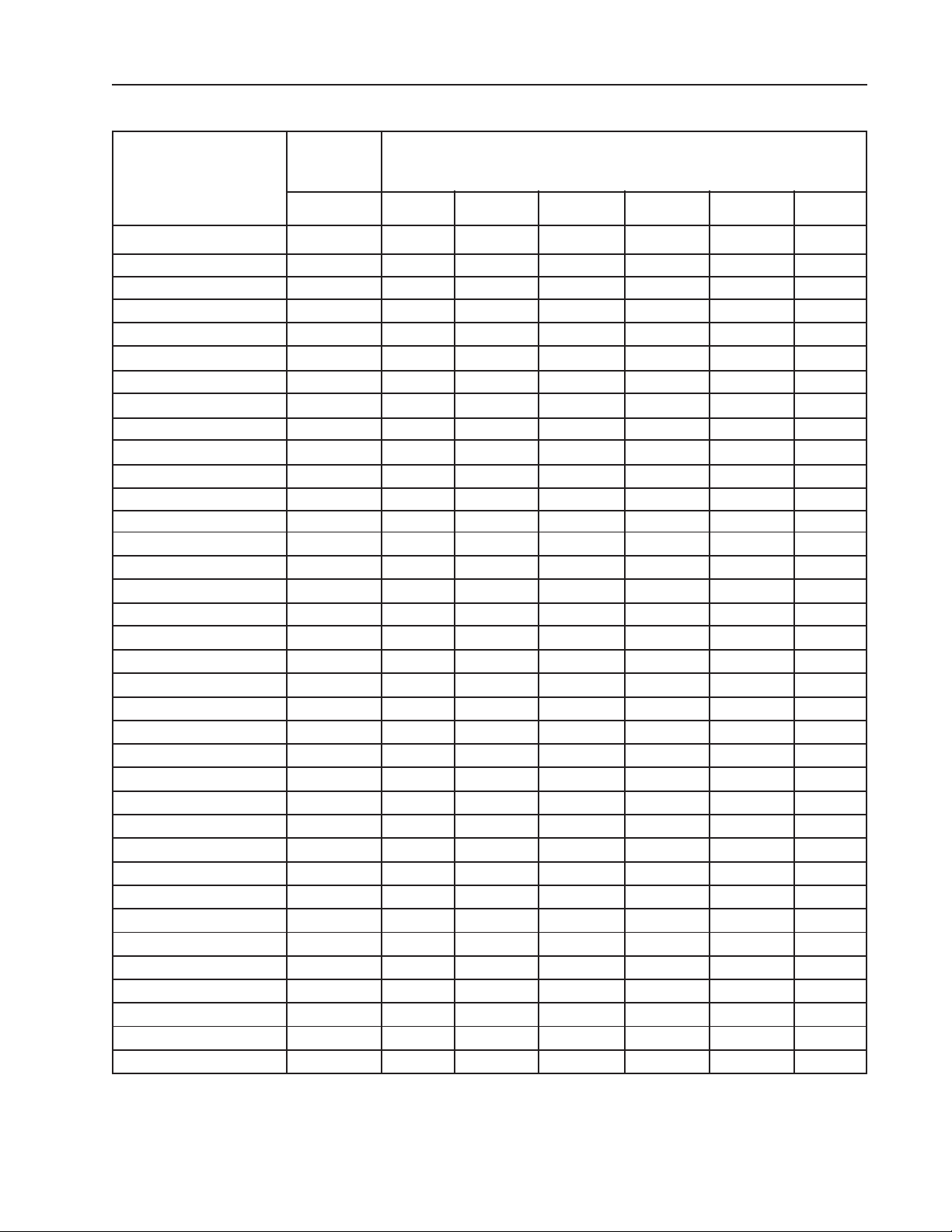
Gas Pipe Size Chart
TOTAL BTU/HR
(for LP Gas correct
total BTU/HR below by
multiplying by .6)
60,000
80,000
100,000
120,000
140,000
160,000
180,000
200,000
300,000
400,000
500,000
600,000
700,000
800,000
900,000
1,000,000
1,100,000
1,200,000
1,300,000
1,400,000
1,500,000
1,600,000
1,700,000
1,800,000
1,900,000
2,000,000
2,200,000
2,400,000
2,600,000
2,800,000
3,000,000
3,200,000
3,400,000
3,600,000
3,800,000
4,000,000
TOTAL
KCAL
HOUR
15000
20000
25200
30200
35200
40300
45300
50400
75600
100800
126000
151200
176400
202000
230000
250000
270000
300000
330000
350000
380000
400000
430000
450000
480000
504000
550000
605000
650000
705000
750000
806000
850000
907000
960000
1000000
GAS PIPE SIZE FOR 1000 BTU (250 KCAL) NATURAL GAS
In figuring total length of pipe, make allowance for tees and elbows.
(25 ft.)
7,62 m
3/4
3/4
3/4
3/4
3/4
3/4
1
1
1
1 1/4
1 1/4
1 1/2
1 1/2
1 1/2
2
2
2
2
2
2
2
2
2
2 1/2
2 1/2
2 1/2
2 1/2
2 1/2
2 1/2
2 1/2
2 1/2
3
3
3
3
3
(50 ft.)
15,24 m
1 1/4
1 1/4
1 1/2
1 1/2
2 1/2
2 1/2
2 1/2
2 1/2
2 1/2
2 1/2
2 1/2
2 1/2
3 1/2
3 1/2
3 1/2
3 1/2
AT 7” W.C. (17.5MM) PRESSURE
(75 ft.)
22,86 m
3/4
3/4
3/4
1
1
1
1
1
2
2
2
2
2
2
3
3
3
3
3
3
3/4
3/4
1
1
1
1
1
1 1/4
1 1/4
1 1/2
1 1/2
2
2
2
2
2
2 1/2
2 1/2
2 1/2
2 1/2
2 1/2
2 1/2
2 1/2
3
3
3
3
3
3
3
3 1/2
3 1/2
3 1/2
3 1/2
3 1/2
3 1/2
(100 ft.)
30,48 m
3/4
1
1
1
1
1 1/4
1 1/4
1 1/4
1 1/2
1 1/2
2
2
2
2
2 1/2
2 1/2
2 1/2
2 1/2
2 1/2
2 1/2
2 1/2
3
3
3
3
3
3
3
3 1/2
3 1/2
3 1/2
3 1/2
3 1/2
3 1/2
4
4
(125 ft.)
38,1 m
3/4
1
1
1
1
1 1/4
1 1/4
1 1/4
1 1/2
1 1/2
2
2
2
2 1/2
2 1/2
2 1/2
2 1/2
2 1/2
2 1/2
3
3
3
3
3
3
3
3 1/2
3 1/2
3 1/2
3 1/2
3 1/2
3 1/2
4
4
4
4
(150 ft.)
45,72 m
1 1/4
1 1/4
1 1/4
1 1/2
1 1/2
2 1/2
2 1/2
2 1/2
2 1/2
2 1/2
2 1/2
3 1/2
3 1/2
3 1/2
3 1/2
3 1/2
3/4
1
1
1
2
2
2
3
3
3
3
3
3
3
4
4
4
4
4
4
Page 17
Page 18
No. of Dryers
Duct Diameter
(in inches)
(in cm)
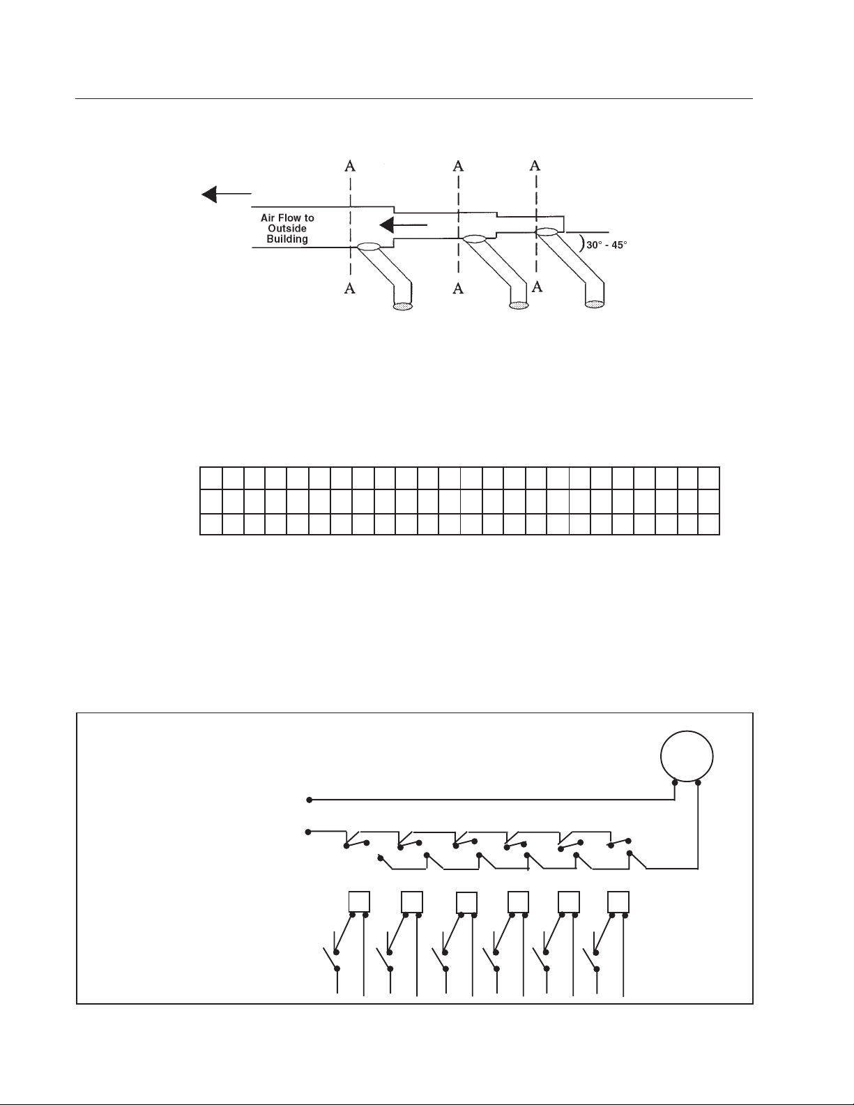
Dryer Installation With Multiple Exhaust
For exhaust duct less than 14 feet (5 m) and 2 elbows
equivalent and less than 0.3 inches (8 mm) static pressure.
DRYER EXHAUSTS
Area of section “A-A” must be equal to the sum of dryer exhaust pipes
entering multiple exhaust pipe. (See chart below.)
DR30
1 2 3 4 5 6 7 8 9 101112131415161718192021222324
8 1214161820222324262728293031323334353637383940
20 30 25 41 46 51 56 58 61 66 68 71 73 76 78 81 84 86 89 91 94 97 99 100
Power Supply
to Fan
Relay Coils
Start and Stop
Switches on
Dryers
_ _ _ _
Page 18
_ _ _ _
_ _ _ _
Exhaust
Booster Fan
_ _ _ _
_ _ _ _
_ _ _ _
Page 19
Dryer Installation with Multiple Exhaust
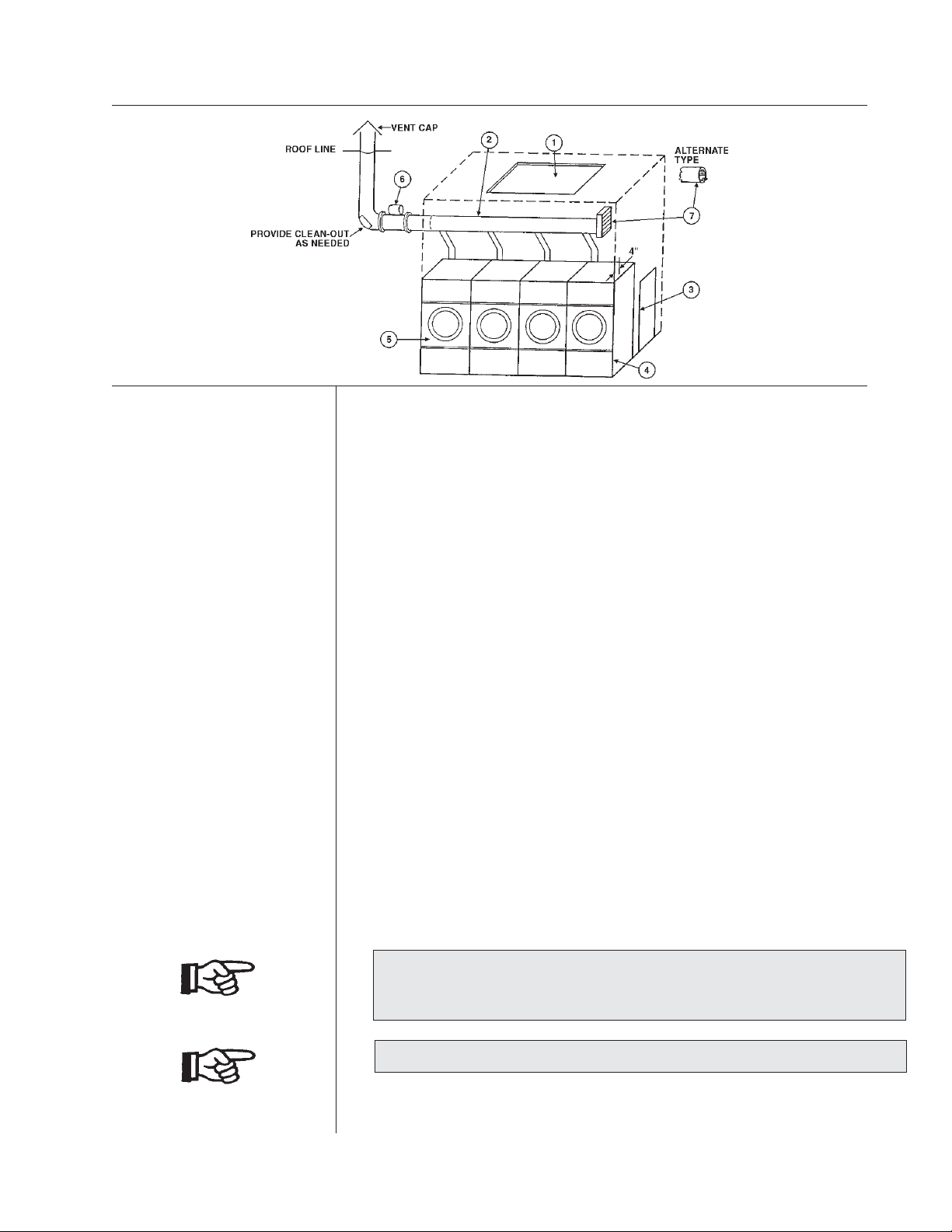
DRYER INSTALLATION
WITH MULTIPLE
EXHAUST
For exhaust duct more than 14 feet (5 m) and 2 elbows equivalent and more
than 0.3 inches (8 mm) static pressure.
1. Make-up air from outside the building may enter enclosure from top or
side walls. (See Dryer Make-Up Air Requirements Chart)
2. Use constant diameter duct with area equal to the sum of dryer duct areas.
EXAMPLE: Six 8 inch (204 mm) diameter ducts = one 19.6 inch
(498 mm) diameter duct in area. Use 20 inch (508 mm) diameter duct or
diameter to match tube-axial fan.
3. Enclosure (plenum) with service door. This separates the dryer air from
room comfort air. If dryers use room air instead of outside air, the heat
loss can be another 25 Btu/hr (6.3 kcal/hr) for each cubic foot per minute
(cfm) used.
4. The installation clearance from all combustible material is 0" ceiling
clearance for the first 4" (102 mm) from the front of the dryer. After the
first 4" (102 mm), the ceiling clearance required is 6" (153 mm). the rear
clearance required is 0", and the side clearance is 1" (26 mm).
5. Heat loss into laundry room from dryer fronts only is about 60 Btu/hr per
square foot (15 kcal/hr per 0.1m²).
6. Flange mounted, belt driven tube-axial fan. Fan must run when one or more
dryers are running. See suggested Automatic Electrical Control Wiring
Diagram on previous page. Must meet local electrical codes. Fan air
flow (cfm or m³/min.) is equal to the sum of dryer air flows, but static
pressure (SP) is dependent on length of pipe and number of elbows.
7. Barometric Bypass Damper—Adjust to closed flutter position with all
dryers and exhaust fan running. Must be located within enclosure.
CAUTION: Never install hot water heaters or other gas appliances in
the same room as dryers. Never install cooling exhaust fans in the same
room as dryers.
CAUTION: Never exhaust dryers with other types of equipment.
Page 19
Page 20

Suggested Minimum Dryer Make-up Air Requirements
Dryer Dryer Pocket Maximum Air Flow Duct Size For Required Make-up
Model Capacity Rate per Pocket Service Connection Air Area per Pocket
lb kg cfm m3/h inch mm sq. in. cm2
C 30 30 13.6 700 1190 8 203 135 871
C 30 E/S 30 13.6 400 680 6 153 77 497
C 30 ST 30 13.6 450 765 6 153 87 561
C 50 50 22.7 800 1360 8 20 3 154 994
C 50 E/S 50 22.7 450 765 6 153 87 561
C 75 75 34 1000 1700 8 203 192 1239
C 75 E/S 75 34 536 911 6 153 103 665
C 75 ST 75 34 1000 1700 12 305 192 1239
HD80 80 36.3 1465 2490 10 254 282 1819
C 110 1 10 50 2200 3740 12 305 422 2723
C 110 E/S 110 50 850 1445 8 203 163 1052
C 125 1 2 5 56.7 2000 3400 12 305 384 2477
C 150 150 68 2250 3825 12 305 432 2787
HD175 175 79.4 2780 4726 12 305 534 3445
HD190 190 86.2 3000 5100 12 305 576 3716
WMC/HD20 20 9.1 450 765 6 1 53 87 561
WMC/HD30 30 13.6 625 1063 8 203 120 774
WMC/HD50 50 22.7 700 1190 8 2 03 135 871
WMC/HD75 75 34 750 1275 8 203 144 929
Notes:
1) The Model C 30 ST has 2 pockets per dryer , each pocket has the above listed characteristics;
each pocket is exhausted separately with a 6" (153mm) duct.
2) The Model C 75 ST has 2 pockets per dryer , each pocket has the above listed characteristics;
both pockets have one 8" (203mm) exhaust manifolded into one 12" (305mm) exhaust duct for
exhaust connection.
3) For the C 30 ST and the C 75 ST Models, the Required Make-up Air Area shown in the table
should be doubled since it is shown per pocket,only .
4) E/S indicates an Energy Saving Model.
Page 20
Page 21
Dryer Installation With Separate Exhaust (Preferred)
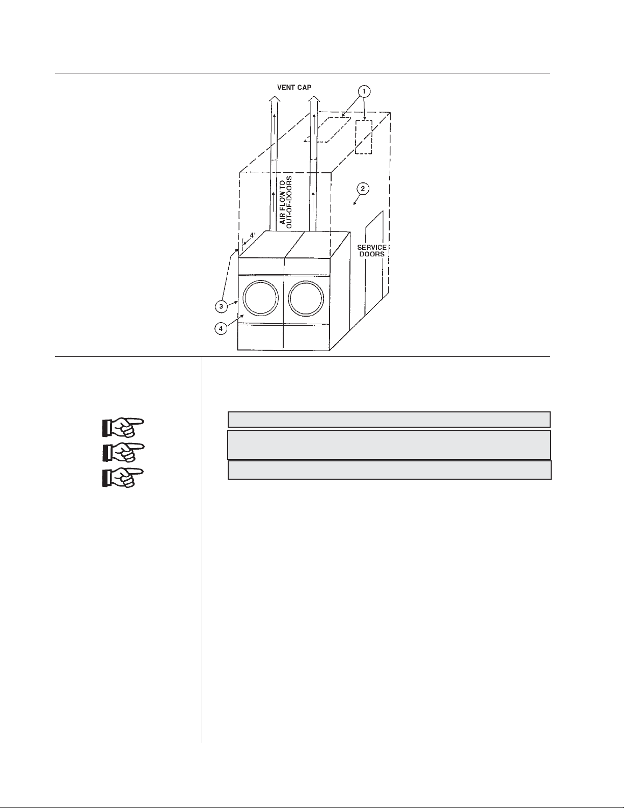
DRYER INSTALLATION
WITH SEPARATE
EXHAUST (PREFERRED)
For ductwork less than 14 feet (5 m) and 2 elbows equivalent and less
than 0.3 inches (8 mm) static pressure:
NEVER exhaust the dryer into a chimney.
NEVER install wire mesh screen over the exhaust or make-up air
area.
NEVER exhaust into a wall, ceiling, or concealed space.
1. Make-up air from outside the building may enter the enclosure from
the top or side walls. (See Dryer Make-Up Air Requirements Chart)
2. Enclosure (plenum) with service door. This separates the dryer air from
the room comfort air. If dryers use room air instead of outside air,
additional heat loss can be another 25 Btu/hr (6.3 kcal/hr) for each
cubic foot per minute (cfm) (.03m³/min.) used.
3. The installation clearance from all combustible material is 0" ceiling
clearance for the first 4" (102 mm) from the front of the dryer. After
the first 4" (102 mm), the ceiling clearance required is 6" (153 mm).
The rear clearance required is 0", and the side clearance is 1" (26 mm).
4. Heat loss into laundry room from dryer front panels is about 60 Btu/hr
per square foot (15 kcal/hr per 0.1m²).
Page 21
Page 22

Exhaust and Venting
DRYER AIR FLOW
INSTALLATION
EXHAUST DUCT
MAKE-UP AIR
Nothing is more important than air flow for the proper operation of a clothes
dryer. A dryer is a pump which draws make-up air from the out-of-doors,
through the heater, through the clothes and then forces the air through the
exhaust duct back to the out-of-doors. Just as in a fluid water pump, there must
be a fluid air flow to the inlet of the dryer, if there is to be the proper fluid air
flow out of the exhaust duct.
In summary, there must be the proper size out-of-doors inlet air opening and an
exhaust duct, size and length of which allows flow through the dryer with no
more than 0.3 inches water column (.8 mbar) static pressure in the exhaust duct.
In some instances, special fans are required to supply make-up air, and/or
booster exhaust fans are required.
FOR BEST DRYING:
1. Exhaust duct maximum length 14 feet (5 m) of straight duct and
maximum of two 90° bends.
2. Use 45° and 30° elbows wherever possible.
3. Exhaust each dryer separately.
4. Do not install wire mesh or other restrictions in the exhaust duct.
5. Use clean-outs in the exhaust duct and clean periodically when needed.
6. Never exceed 0.3 inches (.8 mbar) water column static pressure in the
exhaust duct.
7. Inside surface of the duct must be smooth.
8. Recommend pop rivets for duct assembly.
FOR BEST DRYING:
1. Make-up air from outside the building may enter the enclosure from
the top or side walls. The area of the opening must be a minimum of
210 square inches (135484 mm²) for each dryer. This will deliver the
proper amount of make-up air at an air velocity of approximately
500 fpm (152 m/min) through the opening.
2. Use barometric shutters in the inlet air opening to control air when
dryers are not running.
OTHER
RECOMMENDATIONS
TROUBLESHOOTING
OTHER RECOMMENDATIONS
To assure compliance, consult local building code requirements.
TROUBLESHOOTING
Hot dryer surfaces, scorched clothes, slow drying, lint accumulations,
or air switch malfunction are indicators of exhaust duct and/or makeup air problems.
Page 22
Page 23
Rules for Safe Operation of Dryer
RULES FOR SAFE
OPERATION OF
DRYER
1. Be sure your dryer is installed properly in accordance with the
recommended instructions.
2. CAUTION
Be safe—shut main electrical power supply and gas supply off
externally before attempting service.
3. CAUTION
Never use drycleaning solvents: gasoline, kerosene, or other flammable
liquids in the dryer. Fire and explosion will occur.
Never put fabrics treated with these liquids into the dryer.
Never use these liquids near the dryer.
Always keep the lint screen clean.
Never use heat to dry items that contain plastic, foam or
sponge rubber, or rags coated with oils, waxes or paints. The heat may
damage the material or create a fire hazard. Rubber easily oxidizes,
causing excessive heat and possible fire.
Never dry the above items in the dryer.
4. Never let children play near or operate the dryer. Serious injury will
occur if a child should crawl inside and the dryer is turned on.
5. Never use dryer door opening and top as a step stool.
6. Read and follow manufacturer’s instructions on packages of laundry and
cleaning aids. Heed any warnings or precautions.
7. Never tumble fiberglass materials in the dryer unless the labels say
they are machine dryable. Glass fibers break and can remain in the dryer
and could cause skin irritation if they become mixed into other fabrics.
8. Reference
Wiring diagrams are located on the rear cover of the dryer cabinet.
9. The dryer must not be installed or stored in an area where it will be
exposed to water and/or weather.
ENERGY-SAVING TIPS
1. Install dryer so that you can use short, straight venting.
Turned elbows and long vent tubing tend to increase drying
time. Longer drying time means the use of more energy and
higher operating costs.
2. Operate dryer using full-size loads. Very large loads use extra
energy. Very small loads waste energy.
3. Dry light-weight fabrics separately from heavy fabrics. You
will use less energy and get more even drying results by
drying fabrics of similar weight together.
4. Clean the lint screen area daily. A clean lint screen helps give
faster, more economical drying.
5. Do not open the dryer door while drying. You let warm air
escape from the dryer into the room.
6. Unload the dryer as soon as it stops. This saves having to restart your dryer to remove wrinkles.
Page 23
Page 24

Direct-Spark Ignition Operation
DIRECT SPARK
IGNITION
OPERATION
NOTE: All dryers manufactured are equipped with the DSI (Direct Spark
Ignition) modules. These are designed to increase dryer efficiency and to
reduce dryer operating costs. The main burner is directly ignited from a spark
electrode. A burning flame provides an electrical path for a small amount of
sensing current to allow gas valve operation. If the main burner flame extinguishes for any reason (aside from the thermostatic control) sensing current
will shut down the gas valve and the spark ignition circuit.
1. Once flame is established, the spark shuts off, and the main
burner flame is then electronically monitored by means of a
sensing spark probe which is located over the burner. The gas
valve remains energized (open).
2. If no flame is detected within the first 11 seconds the DSI will
go into a safety “lock-out”. The gas valve is de-energized.
3. Recovery from a safety lockout requires one of the following:
A. Opening the main door thus interrupting power to the DSI
module and allowing dryer diagnostic trouble shooting.
B. Disconnecting the entire dryer from a power source using a
circuit breaker as a switch.
4. By closing the main door the ignition circuit will be restored for
another trial of the ignition circuit.
5. Once the thermostatic control has been satisfied by reaching a
pre-set temperature or the drying timer has been timed out, the
ignition circuit will be de-energized thus extinguishing the
flames.
6. The dryer will continue to run in a cool-down mode without
heat. This process will cool the load to the touch and help to
eliminate wrinkling.
7. The cool - down time is pre-set on some models and manually set
on other dryer models. The cool-down cycle prevents fabric
wrinkles by allowing clothes to reach room ambient temperature
while still in a continuous levitation state until clothes are ready
to be folded or pressed.
Page 24
Page 25
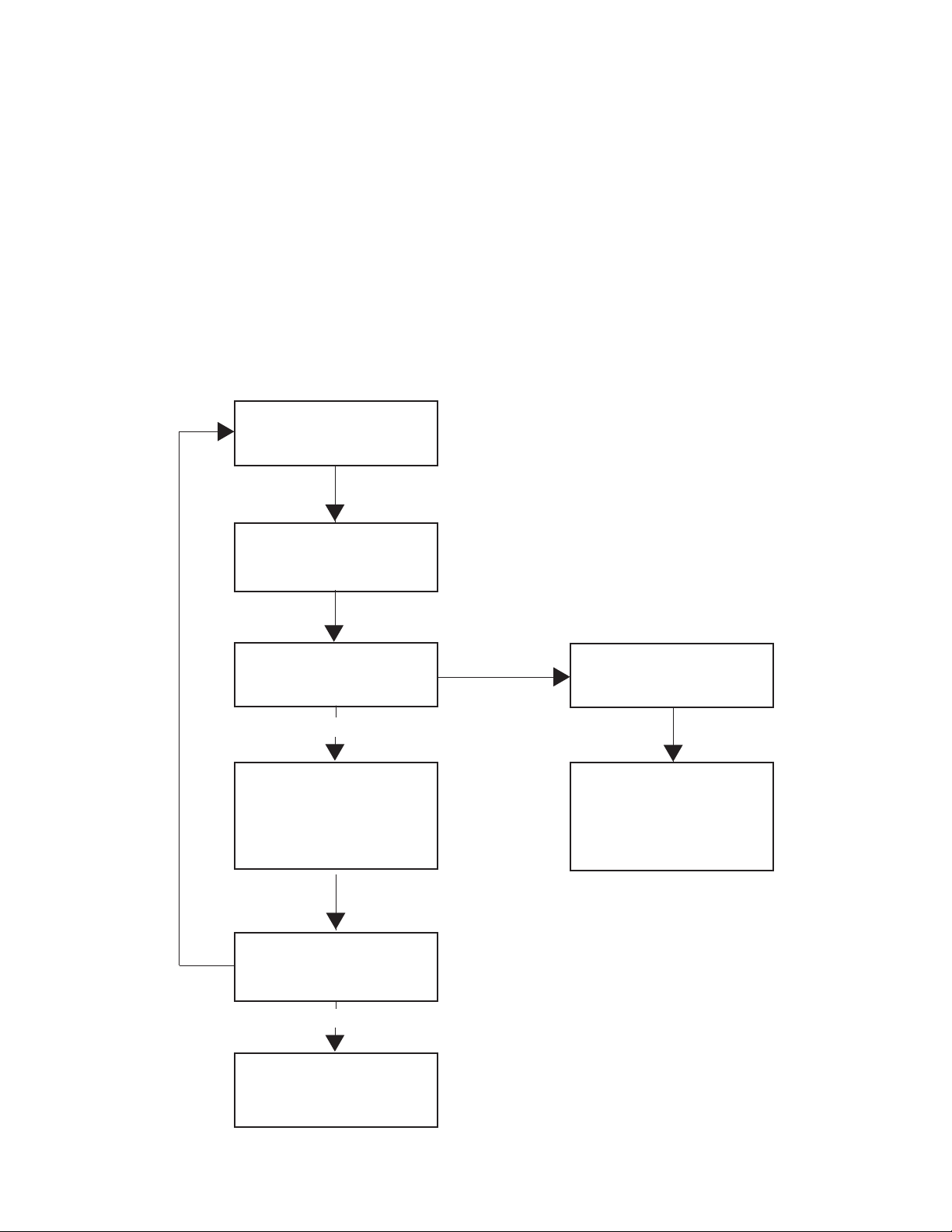
DIRECT SPARK
IGNITION OPERATION
FLOW CHART
The DSI module is powered by a 24 volt AC supplied by a step-down transformer in
series with eight safety interlocks:
A. Timer Switching Device (1)
B. Main Door and Lint Door Switches (2)
C. Sail Switch (1)
D. Under Basket and Burner Housing Thermal Safety Switches (2)
E. Variable Thermostat (1)
F. Push to Start Switch (1)
THERMOSTAT CALLS
FOR HEAT
YES
IGNITION CYCLE
BEGINS, GAS VALVE
ON
MAIN BURNER FLAME
DETECTED
YES
SPARK IGNITION OFF
FLAME MONITOR ON
GAS VALVE ON
FLAME IS LOST DUE
TO POWER OUTAGE,
DOOR OPEN
NO
CONTROL LOCK-OUT
RESET POWER
REQUIRES A MANUAL
RESET (Opening/closing
door, power switch ON/
OFF)
NO
FLAME IS ON UNTIL
THERMOSTAT OR
TIMER IS SATISFIED
Page 25
Page 26
General Maintenance
GENERAL
MAINTENANCE
1. Clean lint trap daily. Remove lint before or after each day of
operation. A clean lint trap will increase the efficiency of the
dryer and the moisture-laden air will be exhausted outside more
quickly.
2. Keep basket and sweep sheets clean. Clean as
often as needed. The basket and sweep sheets are
accessible by removing the front panel of the dryer.
3. Gas burners, steam coils, electric coils. Check and
clean often.
4. Pulleys and belts. Keep clean, as oil and dirt will
shorten the life of a belt. Check periodically for
alignment. Pulley shafts must be parallel and the
grooves must be aligned. Check belt tension
periodically. Adjust tension by movement of Idler
Bracket. Lubricate basket shaft bearings once every two months,
using six grams of high temperature grease. Do not over-
grease.
5. Electric motor. Keep motor clean and dry. Motors
are packed with sufficient grease for 10 years normal
service. After that, bearings and housing should be
cleaned and repacked one-third full with Chevron
Grease No. SR1-2. See label on motor for further
information.
If motor overheats, check voltage and wiring. Low
voltage, inadequate wiring and loose connections are
the main cause of motor failures.
6. Adjustable leveling bolts. One at each corner
permits accurate alignment of dryer.
To adjust: Block one corner of dryer up off the floor,
loosen hex nut. With wrench, turn bolt clockwise to
raise dryer, opposite to lower. Rear bolts are inside the rear
cover of the dryer, and front bolts are inside lint trap
compartment.
Page 26
Page 27

General Maintenance
GENERAL
MAINTENANCE
(continued)
7. Periodically clean and examine exhaust system.
8. Keep dryer area clean and free of gasoline, combustible
materials and other flammable liquids or vapors.
9. Do not obstruct the flow of combustion (make-up) air and
ventilating air.
10. Check gas pressure periodically.
Page 27
Page 28

OPERATING INSTRUCTION - DOUBLE TIMER
OPERATING
INSTRUCTIONS
- DOUBLE
TIMER MODELS
1. After loading the dryer with water washed clothes, close the loading door.
2. Turn the 60 minute drying (heat) timer to the desired time.
3. Turn the 60 minute cooling (air) to the desired time.
4. Select the temperature desired: Low, Medium, or High.
HIGH HEAT
175° F (80° C)exhaust temperature, heavy fabrics and hard to dry, such as cottons, towels,
denim, etc..
PERMANENT PRESS (medium)
155° F (69° C) exhaust temperature, synthetic blends, including a mixed wash load.
LOW HEAT
135° F (58° C) exhaust temperature, delicate, sheer fabrics.
5. Press the “push to start” button to start the drying cycle. The heat or drying light
will stay on until the drying cycle is completed
6. At the end of the drying cycle, the cool down cycle will automatically count down
until all time runs out. The cool down light will stay on until the end of the cycle.
7. Drying cycle will not start unless a few minutes of the cool-down cycle are set on
the cool-down timer.
8. Open the door to shut the dryer off at any time during the cycles.
Page 28
Page 29
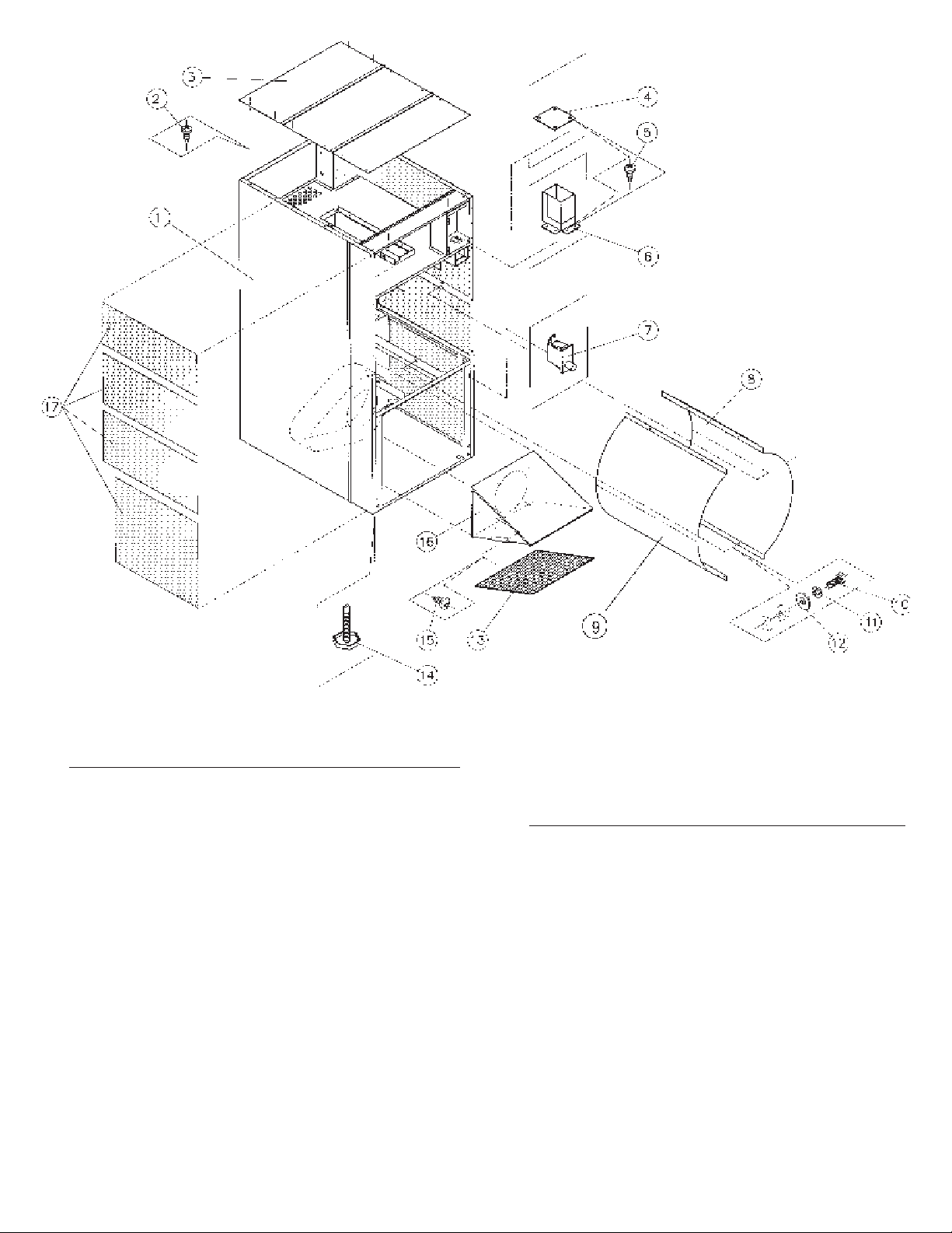
FRONT VIEW
Ref. Part No. Description
No.
1 CSA50036WH Jacket gas/electric (white)
1 CSA-50051WH Jacket steam (white)
2 TU7733 Screw self drilling 8-18 X 1/2”
3 CA-11987-0 Top panel
4 CA-11546-0 Cover plate (non-coin models)
5 TU7733 Screw self drilling 8-18 X 1/2”
6 CSA-01435-0 Coin chute w/a
7 EA-00650-0 Microswitch door
8 CA-11991-0 Right sweepsheet
9 CA-11991-0 Left sweepsheet (gas & elec)
9 CA-13087-0 Left sweepsheet (steam)
Page 29
Ref. Part No. Description
No.
10 CB36 Screw -hex 1/4-20 X 1/2”
11 TU2846 Lockwasher 1/4” medium
12 TU2847 Washer 1/4”
13 CA-10567-0 Lint frame
13 CA-13033-0 LintScreen
14 TU3211 Leveling bolt
15 TU7733 Screw self drilling 8-18 X 1/2”
16 CSA-01528-0 Support filter
17 CSA-01388-0 Insulation side WMC complete
-used on gas models only-
18 CA-13094-0 Insulation cover-steam-left
side-not shown
Page 30
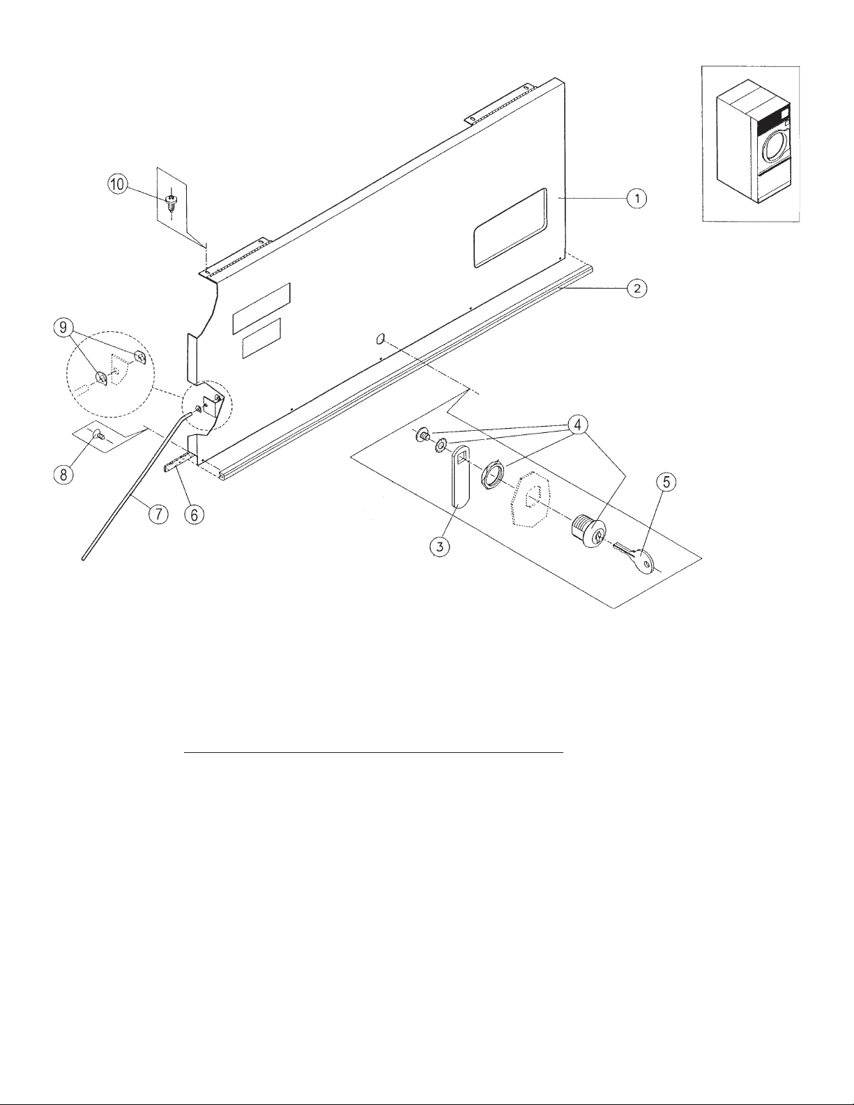
CONTROL DOOR ASSEMBLY
CSA-01582WH Complete control door assy. - Simple microprocessor
CSA-01407WH Complete control door assy. - Double Timer
Note: Door rod assy. is not part of above complete assy.
Ref. Part No. Description
No.
1 CSA-01578WH Control door assy. - Simple microprocessor
1 CSA-01408WH Control door assy. - Double timer
2 CA-00856-0 Trim - Control door
3 LA-11941-0 Cam lock-Control door
4 LA-00121-0 Lock - Control door
5 LA-00119-0 Key - Control door
6 CA-13098-0 Gasket
7 CA-10085-0 Support rod
8 SB-00951-0 Screw -Phillips #8 X 7/16 flat hd.
9 SB-00971-0 Tinnerman push- on fastener
10 TU7733 Screw self drilling 8-18*1/2"
Page 30
Page 31
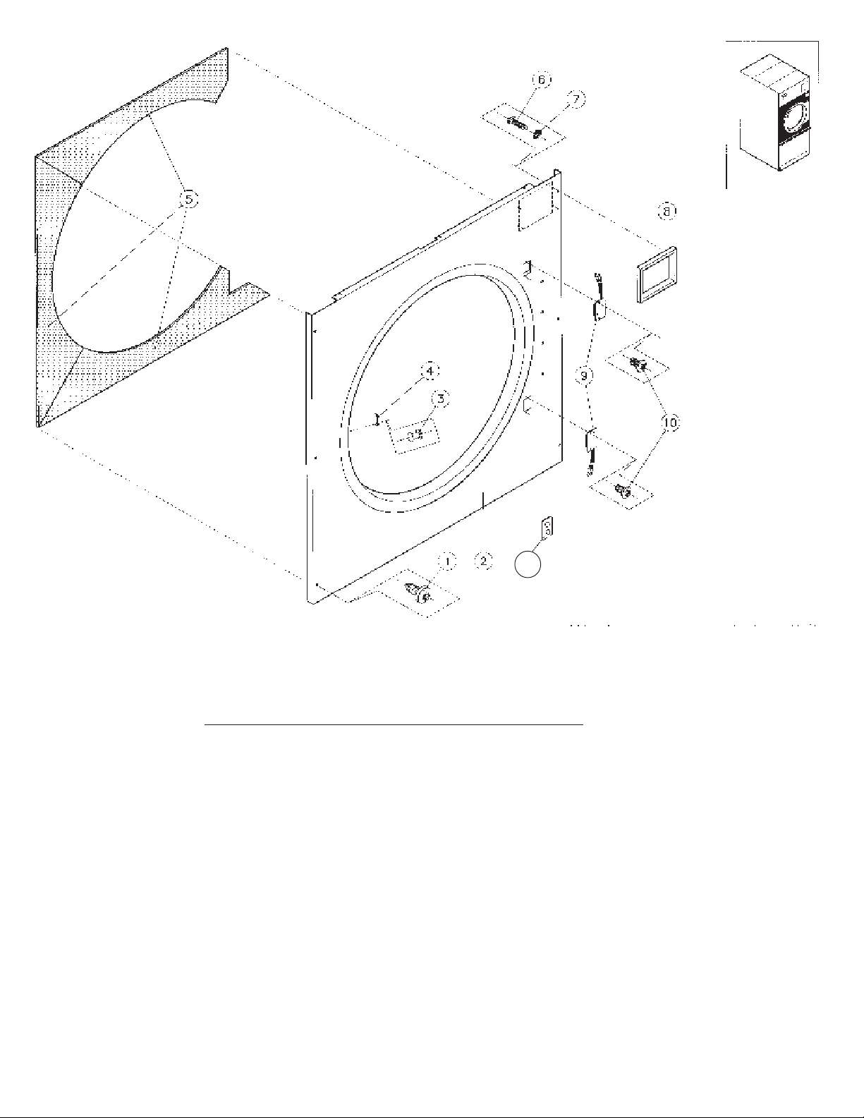
FRONT PANEL ASSEMBL Y
11
Ref. Part No. Description
No.
1 SB-00915-0 Screw self drilling #10-16 X 5/8
2 CSA-01564WH Front panel, welded assy.-Coin
2 CSA-01563WH Front panel, welded assy-OPL
3 TU5158 Latch & catch asm.
5 CA-00675-1 Insulation
6 SB-00924-0 Screw 4-40*3/8 taptite
7 SB-00938-0 Washer 4 external tooth
8 CA-00699-0 Bezel - Coin box
9 ESA-00862-0 Reed switch assy.
10 SB-00975-0 Screw 6-32*1/4 phillips
11 EA-00827-0 Mounting plate - Reed switch
Page 31
Page 32
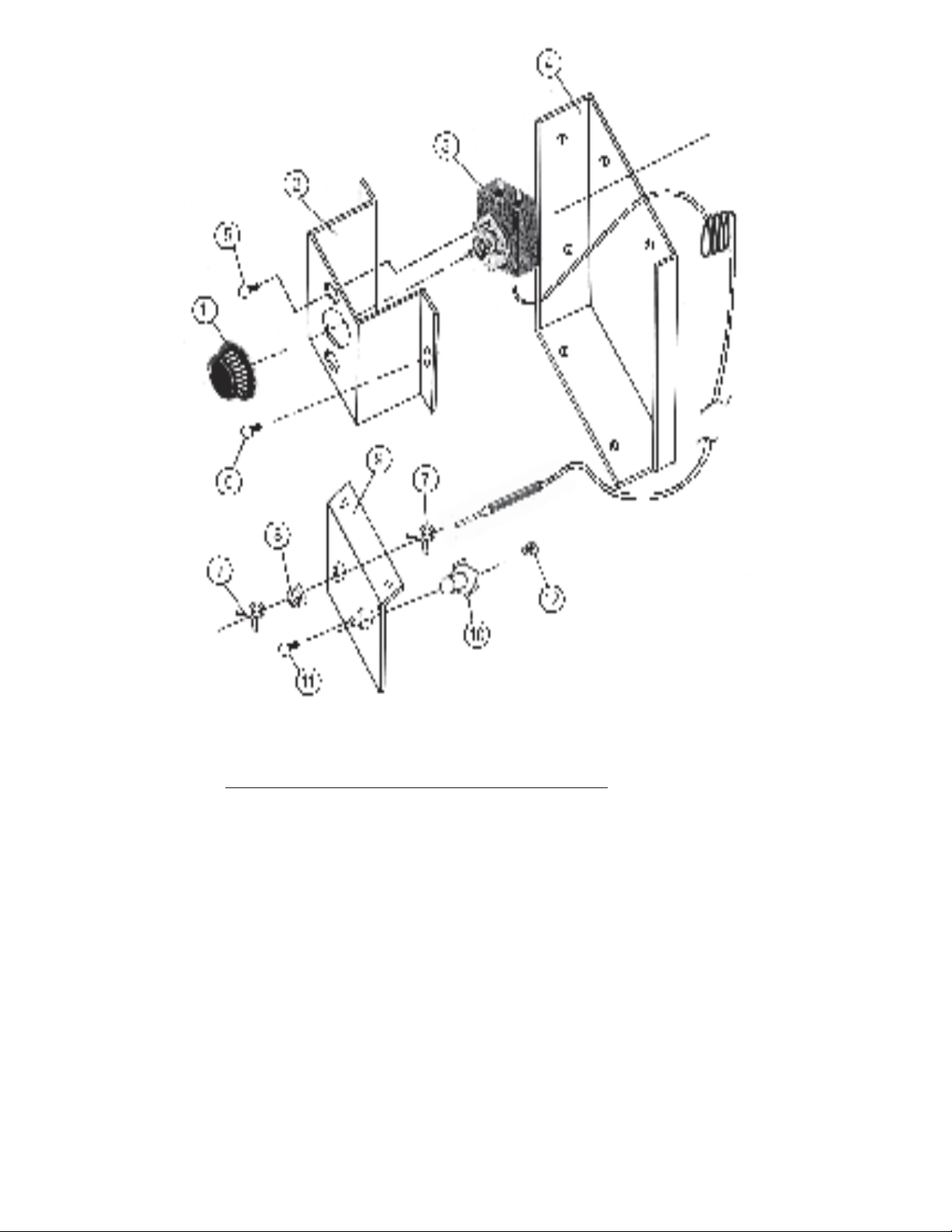
THERMOSTAT ASSEMBLY DOUBLE TIMER
Ref. Part No. Description
No.
1 EA-00607-0 Thermostat knob
2 CA-13213-0 Thermostat bracket
3 EA-00606-0 Thermostat
4 CA-13215-0 Thermostat bracket adapter
5 TU3624 Screw 6 - 32 X 1/4”
6 TU7733 Screw - self drilling 8 - 18 X 12”
7 EA-00434-0 Clip - 3/8” spring
8 EA-00608 - 0 Grommet / rubber
9 CA-13214-0 Plate
10 EA-00594-0 Thermostat - HI-Limit
11 SB-00828-0 Screw 8-32 X 1/2”
12 TU3266 Nut-brass 8-32
NOTE: Items 1 thru 6
mounted in front wire
box. Items 7 thru 12 are
mounted under the
basket
Page 32
Page 33
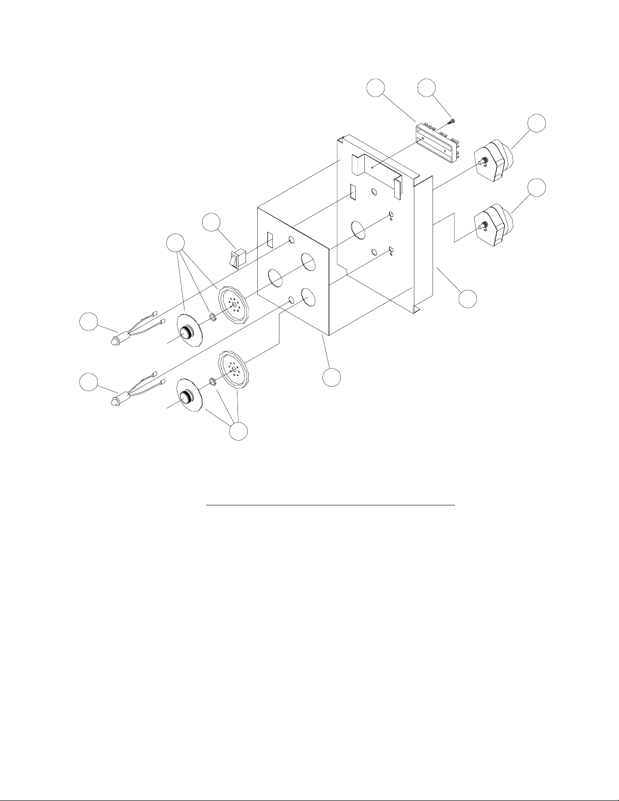
WIRE BOX ASSEMBLY DOUBLE TIMER
67
2
2
3
2
5
1
1
2
4
Ref. Part No. Description
No.
CSA-01608WH Wire box door assy complete
1 TUT316 Light LED 24V
2 EA-11614-0 Timer-manual 24V - 60 min. complete
3 EA-00619-0 Switch - start
4 CA-13170-0 Overlay- dual timer non-rev
5 CSA-01607WH Wire box door .
6 SB-00865-0 Screw-self drilling #6-20 X 12”
7 EA-00210-0 Terminal block
8 ESA-00967-0 Wire harness (not shown)
9 SB-00868-0 Bushing 7/8”
Page 33
Page 34
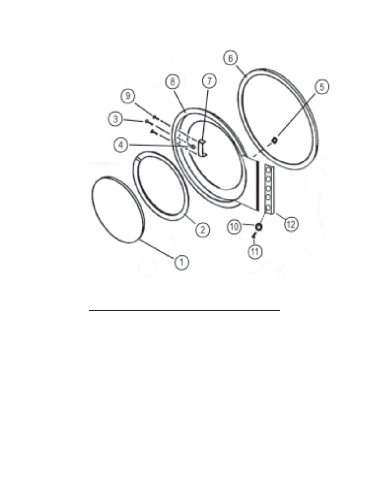
DOOR ASSEMBLY
Ref. Part No. Description
No.
MSD-00859WH Complete door assy (consists of items 1 thru 9 only)
1 MD-00362-0 Door Glass - clear
2 MD-00354-0 Gasket - door glass - straight
3 TU5158 Latch & catch pin asm.
5 MD-00337-0 Magnet - reed switch
6 MD-00338-0 Gasket - door rim
7 TU2874 Basket door handle
8 MSD-00857WH Basket door
9 TU3215 Screw #10 - 32 X 3/8”
10 SB-00852-0 Washer 1/4” external starluck
11 SB-00921-0 Screw 1/4”-20 round head
12 MD-00348-0 Hinge spacer
Page 34
Page 35
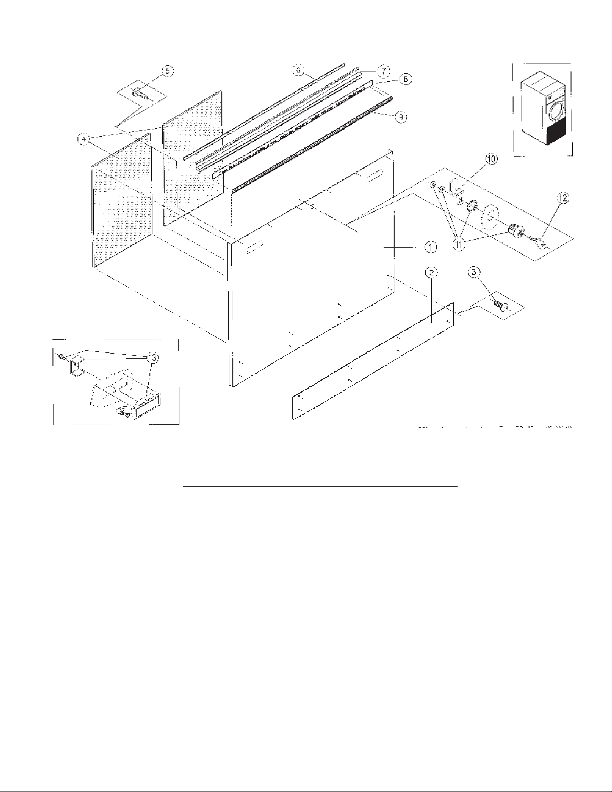
LINT DOOR ASSEMBLY
For OPL models only.
Ref. Part No. Description
No.
CSA-01386WH Complete Asm - WMC30 OPL
CSA-01465WH Complete Asm - WMC30 Coin
1 CSA-01387WH Lint door w/latch holes(white) OPL
1 CSA-01098WH Lint door w/lock holes(white) Coin
2 CA-00833-0 Kickplate
3 SB-00949-0 Fastener plastic kickplate
4 CA-11930-0 Insulation lower frontpanel WMC30
5 SB-00915-0 Screw self drilling #10-16 X 5/8
6 TU2853 Gasket
7 CA-00646-0 Handle lint door
8 CA-00841-0 Label (not part of assy.)
9 CA-00655-0 Trim-rubrail-specify 33” long
10 LA-11359-0 Cam lock
11 LA-00121-0 Lock
12 LA-00119-0 Key
13 LA-00124-0 Latch - trigger
Page 35
Page 36
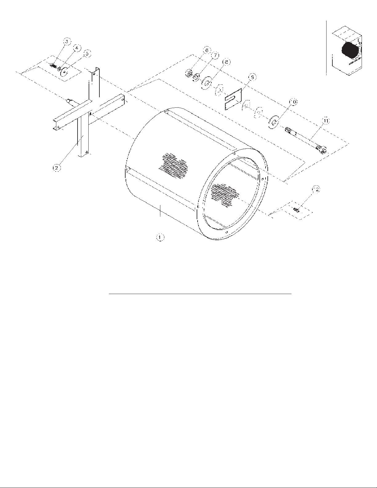
BASKET & SPIDER ASSEMBL Y
Ref. Part No. Description
No.
CSA-01539-0 Basket & Spider Asm.WMC30 - S.S.
CSA-01637-0 Basket & Spider Asm.WMC30 - Galv.
1 CSA-01538-0 Stainless steel basket assy.
1 CSA-01636-0 Galvanized basket assy.
2 CSA-01434-0 Spider assy.
3 TU5439 Screw-cap 5/16-18 X 3/4"
4 TU2814 Lock washer 5/16"
5 SB-00843-0 Washer fender 3/8” X 1 1/2”
6 SB-00906-0 Nut 5/16” - 18 stover
7 TU2814 Lock washer 5/16”
9 TU7006 Shim
10 CA-13208 Basket rib support
11 DA-00445-0 Tie rod (4 req’d)
12 SB-00965-0 Screw-button cap 5/16 - 18
Page 36
Page 37
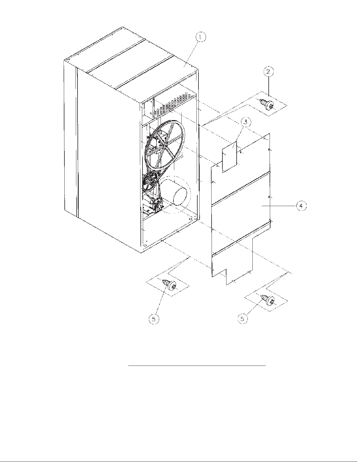
REAR VIEW
Ref. Part No. Description
No.
1 CA-11987-0 Top panel
2 TU7733 Screw self drilling 8-18*1/2"
3 CA-11936-0 Cover plate
4 CA-11975-0 Backpanel
5 TU7733 Screw self drilling 8-18*1/2"
Page 37
Page 38
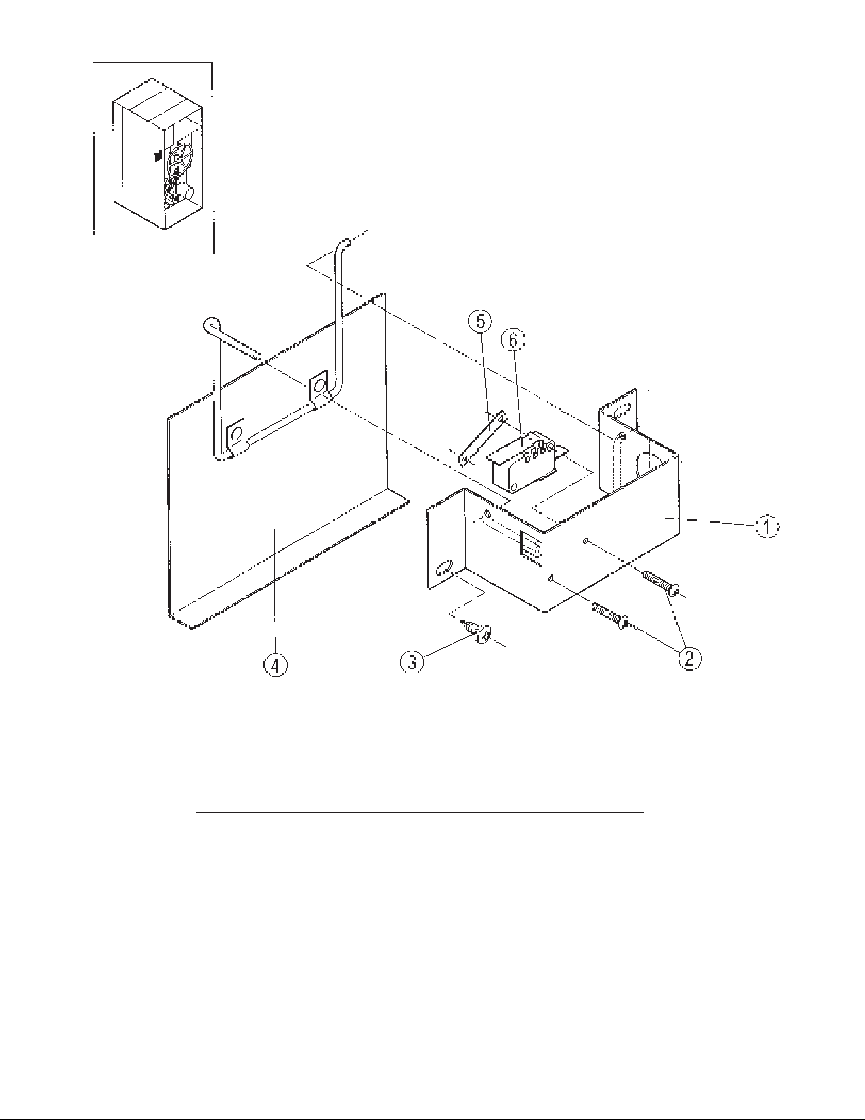
AIR SWITCH ASSEMBLY
Ref. Part No. Description
No.
CSA-01334-0 Sail switch assy. complete
1 CA-11854-0 Bracket sailswitch
2 SB-00955-0 Screw phillips #4 X 3/4"
3 TU7733 Screw self drilling 8-18*1/2"
4 CSA-01669-0 Sailswitch plate and rod assy.
5 SB-00954-0 Clip-twin-Tinnerman
6 EA-00618-0 Microswitch
Page 38
Page 39
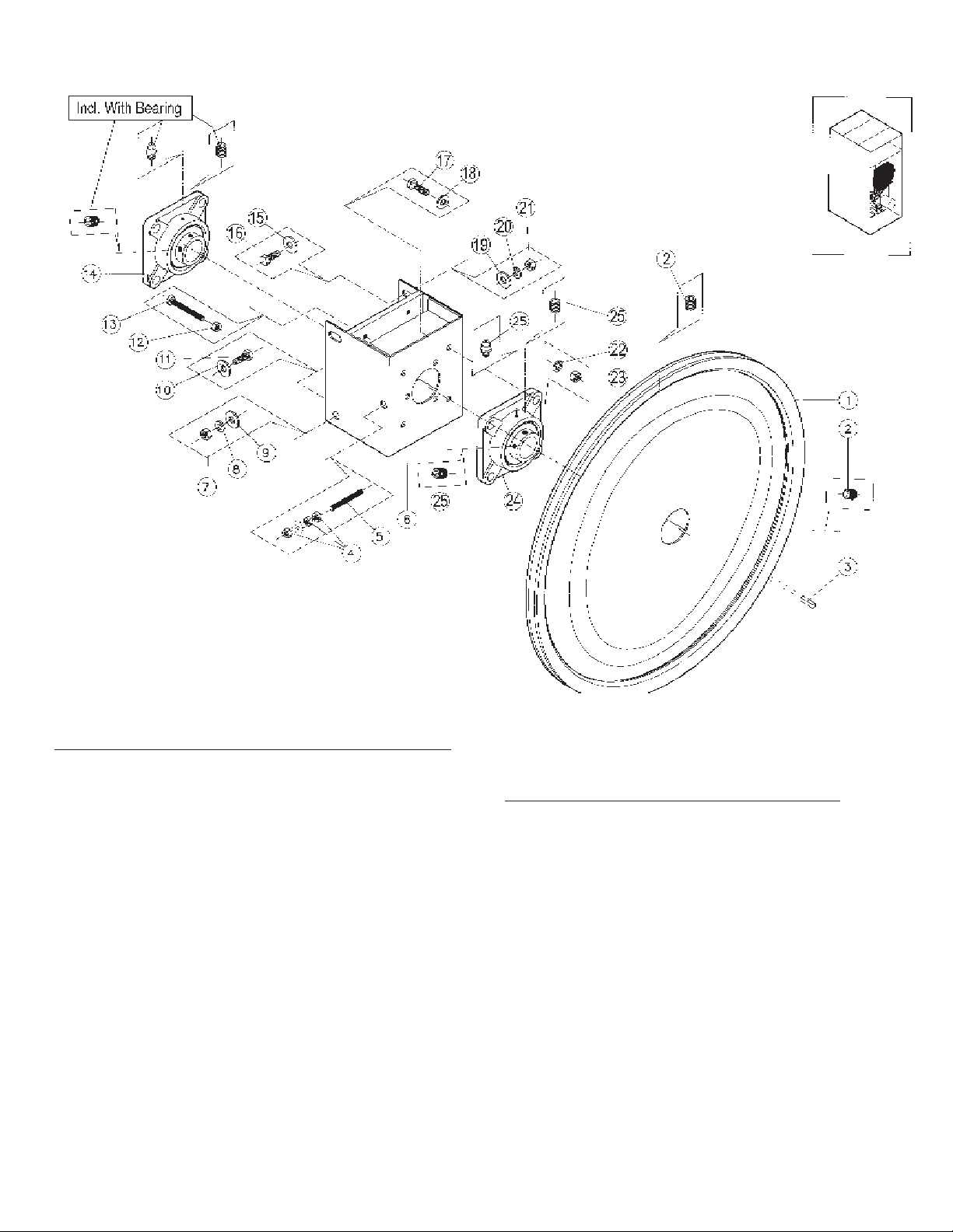
BASKET BEARINGS, SUPPORT, AND SHEAVE
Ref. Part No. Description
No.
1 DA-11911-0 Pulley - basket
2 Part of pulley
3 TU5887 Key
4 C249 Hex nut 5/16-18"
5 SB-00876-0 Stud - 5/16 - 18”
6 DSA-00728-0 Bearing box assy.
7 TU4787 Hex nut 3/8-16"
8 VSB134 Lock Washer 3/8"
9 IB140 Washer 3/8"
10 IB140 Washer 3/8"
11 IB139 Screw 3/8-16*1-1/4"
12 C249 Hex nut 5/16-18"
13 SB-00935-0 Screw cap 5/16 - 18 X 3
14 DA-00421-0 Bearing flange 1 3/8”
Ref. Part No. Description
No.
15 IB140 Washer 3/8"
16 IB139 Screw 3/8-16*1-1/4"
17 IB139 Screw 3/8-16*1-1/4"
18 IB140 Washer 3/8"
19 IB140 Washer 3/8"
2 0 VSB134 Lock Washer 3/8"
21 TU4787 Hex nut 3/8-16"
2 2 VSB134 Lock Washer 3/8"
23 TU4787 Hex nut 3/8-16"
24 DA-00421-0 Bearing - flange 1 3/8”
2 5 Part of bearing
Page 39
Page 40
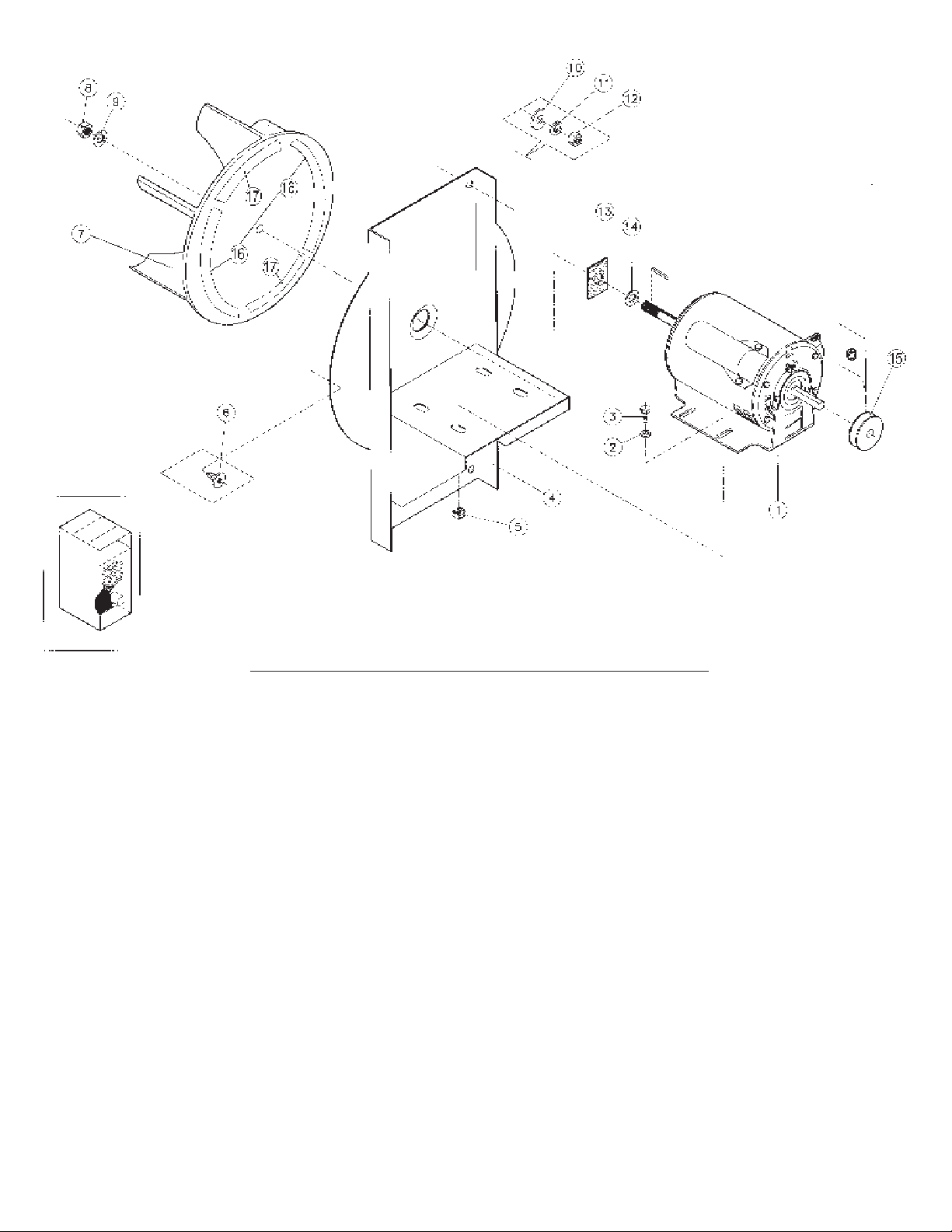
MOTOR & FAN ASSEMBLY- NON-REVERSING
Ref. Part No. Description
No.
1 DA-00428-0 Fan motor 1/2 HP 115/208/230/60/50/1
2 TU2814 Lock washer 5/16”
3 TU5439 Screw-cap 5/16-18 X 3/4"
4 DSA-00801-0 Motor mount w/a - non-rev.
5 SB-00842-0 Nut, grip, Tinnerman
6 SB-00836-0 Screw, phillips, pancake head
7 DSA-00773-0 Fan (12")
8 SB-00813-0 Nut 1/2-20" - Left hand thread
9 SB-00847-0 Washer -1" O.D. X .505 I.D.
10 IB140 Washer cut 3/8"
1 1 VSB134 Washer lock 3/8"
12 TU4787 Hex nut 3/8-16"
13 DA-00460-0 Seal, acoustical
14 SB-00847-0 Washer -1" O.D. X .505 I.D.
15 DA-00509-0 Sheave, 60 cycle, 1/2” bore
15 DA-00508-0 Sheave, 50 cycle, 1/2” bore
16 TU2473 Gasket - curved (2 req’d)
17 TU2474 Gasket - straight (2 req’d)
Page 40
Page 41
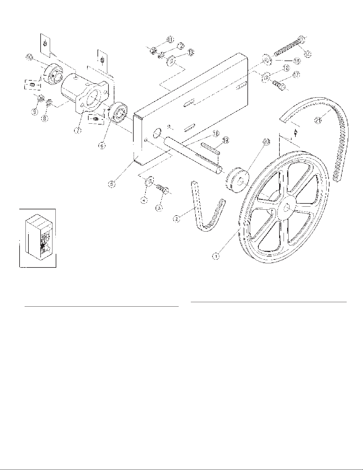
IDLER ASSEMBLY
Ref. Part No. Description
No.
1 DA--00531-0 Idler pulley 9”
2 DA-00523-0 Basket belt - non-reversing - AX66
2 DA-00523-0 Basket belt -reversing - AX66
3 FB124 Screw 5/16-18*1"
4 VSB130 Washer 5/16"
5 CA-12059-0 Idler adjusting plate
6 DA-00518-0 Bearing
7 DA-00517-0 Housing - idler bearing
8 TU2814 Lock washer 5/16"
9 C249 Hex Nut 5/16-18"
10 DA-00518-0 Bearing
Page 41
Ref. Part No. Description
No.
11 C249 Hex Nut 5/16-18"
12 TU2814 Lock Washer 5/16"
1 3 VSB130 Washer 5/16"
14 SB-00935-0 Screw 5/16”-18 X 3”
1 5 VSB130 Washer 5/16"
1 6 VSB130 Washer 5/16"
17 TU5439 Screw 5/16-18*1"
18 DA-11711-0 Idler shaft
1 9 TUD0187 Key 3/16 square 2-1/2"
20 DA-00530-0 V-belt pulley 2-1/2”
21 DA-00525-0 Belt - motor to idler pulley AX51
Non-reversing
21 TU10888 Belt - motor to idler pulley AX64
Reversing
Page 42
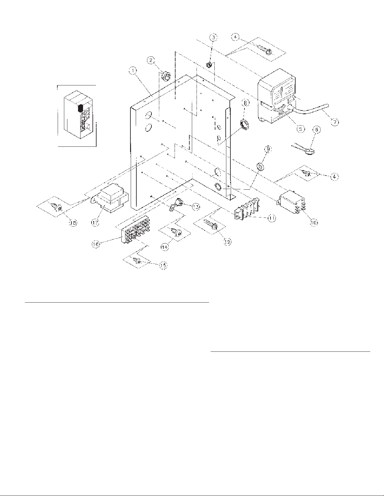
REAR CONTROL PANEL ASSEMBLY - NON-REVERSING
DOUBLE TIMER MODELS-GAS ONLY
Ref. Part No. Description
No.
ESA-00966-0 Wire box assy, rear, gas - 115V - 2 timer
ESA-00974-0 Wire box assy, rear, gas - 208/240V - 2 timer
1 CA-11935-0 Rear wiring box
2 SB-00868-0 Bushing, insulating 7/8”
3 SB-00867-0 Bushing, insulating 1/2”
4 TU7733 Screw self drilling 8-18 X 1/2"
5 GA-00765-0 Ignitor ram III DSI
6 EA-00651-0 Varistor/relay/motor
7 GA-00803-0 High voltage lead/ram
8 TU2490 Plug button
9 EA-00680-0 Knock-out plug
10 EA-11618-0 Motor relay- 3 pole -30amp - 24V
Ref. Part No. Description
No.
11 EA-00467-0 Terminal block
12 TU7733 Screw self drilling 8-18 X 1/2"
13 TU7738 Ground lug
14 TU7733 Screw self drilling 8-18 X 1/2"
15 SB-00865-0 Screw self drilling 6 - 20 X 1/2
16 EA-00210-0 Terminal block
17 EA-00646-0 Transformer 24V
18 TU7733 Screw self drilling 8-18 X 1/2"
Page 42
Page 43
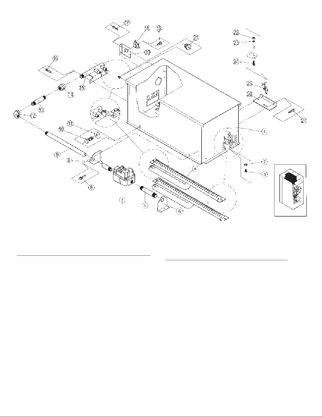
GAS HEATING UNIT
Ref. Part No. Description
No.
GSA-00784-0 Comp. assy. - Nat. gas
GSA-00775-0 Comp. assy. - LP gas
1 GSA-00255-0 Housing gas burner
2 TU11613-0 Lock washer 10 external tooth
3 SB-00831-0 Screw 10-32*3/8"
4 GA-00756-0 Gas burner
5 LB20 Nipple - 1/2” X 3”
6 CA-11878-0 Bracket -pipe
7 GA-00770-0 Gas valve 24V 1/2"(Nat.gas)
8 TU7733 Screw self drilling 8-18 X 1/2"
9 FG274 Gas pipe 1/2 X 30”
10 TU5439 Screw cap 5/16-18X3/4"
1 1 VSB130 Washer 5/16"
12 390501053 Elbow 1/2"
13 OP308 Nipple 1/2” X 4”
Page 43
Ref. Part No. Description
No.
14 OP314 Union (gas pipe)
15 GSA-00508-0 Manifold assy.
16 TU7733 Screw self drilling 8-18X1/2"
17 TU7733 Screw self drilling 8-18X1/2"
18 EA-00245-0 Thermostat HI LIMIT -330
19 TU7733 Screw self drilling 8-18 X 1/2"
20 CA11028-0 Bracket thermostat
21 GA-00761-0 Gas orifce (specify size)
22 TU3266 Hex nut-brass 8-32"
2 3 AT368 Lock washer #8
24 M262 Screw mach.truss head 8/32X3/8"
25 GA-11003-0 Gas ignition electrode
26 GA-10457-0 Bracket
27 TU7733 Screw self drilling 8-18 X 1/2"
0
 Loading...