

Page 1

iPECS-MG
Hardware Description & Installation
Manual
Please read this manual carefully before
operating System. Retain it for future reference
Page 2

iPECS-MG
Hardware Description and Installation Manual Issue 1.1
Regulatory Information
Before connecting the iPECS-MG to the telephone network, you may be required to notify your
local serving telephone company of your intention to use “customer provided equipment”. You
may further be required to provide any or all of the following information:
PSTN line Telephone numbers to be connected to the sy stem Telephone Number
Model name iPECS–MG
Local regulatory agency registration number locally provided
Ringer equivalence 1.1
Registered jack RJ–45
The required regulatory agency registration number is available from your local Ericsson-LG
representative.
This equipment complies with the following regulatory standards, that is, the safety
requirements of EN60950-1, UL 60950-1/CSA C22.2 No. 60950-1-03 and the EMC
requirement of EN55022 and EN55024.
If the telephone company determines that customer provided equipment is faulty and may
possibly cause harm or interruption in service to the telephone network, it should be
disconnected until repair can be affected. If this is not done, the telephone company may
temporarily disconnect service.
The local telephone company may make changes in its communications facilities or
procedures. If these changes could reasonably be expected to affect the use of the iPECS-MG
or compatibility with the network, the telephone company is required to give advanced written
notice to the user, allowing the user to take appropriate steps to maintain telephone service.
The iPECS-MG complies with rules regarding radiation and radio frequency emission as
defined by local regulatory agencies. In accordance with these agencies, you may be required
to provide information such as the following to the end user.
Page 3

iPECS-MG
Hardware Description and Installation Manual Issue 1.1
FCC Interference Statement
Note
This equipment has been tested and found to comply with the limits for a Class B
digital device, pursuant to part 15 of the FCC Rules. These limits are designed to
provide reasonable protection against harmful interference in a residential installation.
This equipment generates, uses, and can radiate radio frequency energy and, if not
installed and used in accordance with the instructions, may cause harmful interference
to radio communications. However, there is no guarantee that interference will not
occur in a particular installation. If this equipment does cause harmful interference to
radio or television reception, which can be determined by turning the equipment off and
on, the user is encouraged to try to correct the interference by one or more of the
following measures:
Reorient or relocate the receiving antenna.
Increase the separation between the equipment and receiver.
Connect the equipment into an outlet on a circuit different from that to which the
receiver is connected.
Consult the dealer or an experienced radio/TV technician for help.
Modifications not expressly approved by the manufacturer could void the user's authority to
operate the equipment under FCC rules.
This device complies with part 15 of the FCC Rules. Operation is subject to the following two
conditions:
This device may not cause harmful interference, and this device must accept any
interference received, including interference that may cause undesired operation.
Compliance Statement for Canada
This Class B digital apparatus complies with Canadian ICES-003.
Cet appareil numérique de la classe B est conforme à la norme NMB-003 du Canada.
[EU]
European Union Declarations of Conformity
Ericsson-LG Co., Ltd. declare that the equipment specified in this document bearing the “ CE”
mark conforms to the European Union Radio and Telecommunications Terminal Equipment
Directive(R&TTE 1999/5/EC), including the Electromagnetic Compatibility
Directive(2004/108/EC) and Low Voltage Directive(2006/95/EC).
Copies of these Declarations of Conformity (DoCs) can be obtained by contacting your local
sales representative.
Warning
This is a class A product. In a domestic environment this product may cause radio interference
in which case the user may be required to take adequate measures.
Page 4

iPECS-MG
Hardware Description and Installation Manual Issue 1.1
[USA/CSA]
FCC/IC Interference Statement
This equipment has been tested and found to comply with the limits for a Class A dig it al de v ice,
pursuant to part 15 of the FCC Rules.
These limits are designed to provide reasonable protection against harmful interference when
the equipment is operated in a commercial environment. This equipment generates, uses, and
can radiate radio frequency energy and, if not installed and used in accordance with the
instruction manual, may cause harmful interference to radio communications. Operation of this
equipment in a residential area is likely to cause harmful interference in which case the user
will be required to correct the interference at his own expense.
Change or modifications not expressly approved by the party responsible for compliance could
void the user’s authority to operate the equipment under FCC rules.
This device complies with part 15 /RSS-GEN of the FCC/IC rules. Operation is subject to the
following two conditions:
(1)This device may not cause harmful interference; and (2) This device must accept any
interference received, including interference that may cause undesired operation.
This Class A digital apparatus complies with Canadian ICES-003.
Cet appareil numérique de la classe A est conforme à la norme NMB-003 du Canada.
The use of this device in a system operating either partially or completely outdoors may require
the user to obtain a license for the system according to the Canadian regulations.
CAUTION : Any changes or modifications in construction of this device which are not expressly
approved by the party responsible for compliance could void the user's authority to operate the
equipment.
The following safety requirements are related to USA and Canada.
1. Replaceable batteries
"CAUTION: Risk of Explosion if Battery is replaced by an Incorrect Type. Dispose of Used
Batteries According to the Instructions."
2. Separation of TNV and SELV - Pluggable A
"The separate protective earthing terminal provided on this product shall be permanently
connected to earth."
3. Leakage currents due to ringing voltage - Earthing installation instructions
1) A supplementary equipment earthing conductor is to be installed between the product or
system and earth, that is, in addition to the equipment earthing conductor in the power supply
cord.
2) The supplementary equipment earthing conductor may not be smaller in size than the
unearthed branch-circuit supply conductors. The supplementary equipment earthing
conductor is to be connected to the product at the terminal provided, and connected to earth
Page 5
iPECS-MG
required to correct the interference.”
Hardware Description and Installation Manual Issue 1.1
in a manner that will retain the earth connection when the power supply cord is unplugged.
The connection to earth of the supplementary earthing conductor shall be in compliance with
the appropriate rules for terminating bonding jumpers in Part K of Article 250 of the National
Electrical Code, ANSI/NFPA 70 and Article 10 of Part 1 of the Canadian Electrical Code, Part
1, C22.1. Termination of the supplementary earthing conductor is permitted to be made to
building steel, to a metal electrical raceway system, or to any earthed item that is permanently
and reliably connected to the electrical service equipment earthed.
3) Bare, covered, or insulated earthing conductors are acceptable. A covered or insulated
conductor must have a continuous outer finish that is either green, or green with one or more
yellow stripes."
4. Telephone line cord
"CAUTION: To reduce the risk of fire, use only No. 26 AWG or larger (e.g., 24 AWG) UL Listed
or CSA Certified Telecommunication Line Cord".
5. Rack Mount
1) Elevated Operating Ambient - If installed in a closed or multi-unit rack assembly, the operating
ambient temperature of the rack environment may be greater than room ambient. Therefore,
consideration should be given to installing the equipment in an environment compatible with
the maximum ambient temperature (Tma) specified by the manufacturer.
2) Reduced Air Flow - Installation of the equipment in a rack should be such that the amount of
air flow required for safe operation of the equipment is not compromised.
3) Mechanical Loading - Mounting of the equipment in the rack should be such that a hazardous
condition is not achieved due to uneven mechanical loading.
4) Circuit Overloading - Consideration should be given to the connection of the equipment to the
supply circuit and the effect that overloading of the circuits might have on overcurrent
protection and supply wiring. Appropriate consideration of equipment nameplate ratings
should be used when addressing this concern.
5) Reliable Earthing - Reliable earthing of rack-mounted equipment should be maintained.
Particular attention should be given to supply connections other than direct connections to the
branch circuit (e.g. use of power strips)."
WARNING
“This equipment generates and uses R.F. energy, and if not installed and used in
accordance with the Instruction Manual, it may cause interference to radio
communications. It has been tested and found to comply with the appropriate limits
for a telecommunication device. The limits are designed to provide reasonable
protection against such interference, when operated in a commercial environment.
Operation of this equipment in a residential area could cause interference, in which
case the user, at his own expense, will be required to take whatever measures may be
Page 6

iPECS-MG
Hardware Description and Installation Manual Issue 1.1
Revision History
ISSUE DATE CONTENTS OF CHANGES REMARK
1.0 2009.12 Initial Release
1.1 2012.12 General edits
Updates for T1-PRI
Added LDP DPB (Door Phone Box)
Added BRIB
Removed detailed A dmi n instru ctions
Changed the new CI (Ericsson-LG)
Copyright© 2010 Ericsson-LG Co., Ltd. All Rights Reserved
This material is copyrighted by Ericsson-LG Co., Ltd. (Ericsson-LG). Any unauthorized
reproductions, use or disclosure of this material, or any part thereof, is strictly prohibited and is
a violation of Copyright Laws. Ericsson-LG reserves the right to make changes in specifications
at any time without notice. The information furnished by Ericsson-LG in this material is believed
to be accurate and reliable, but is not warranted to be true in all cases.
iPECS is trademark of Ericsson-LG Co., Ltd.
All other brand and product names are trademarks or registered trademarks of their respective
companies.
Page 7

iPECS-MG
Hardware Description and Installation Manual Issue 1.1
Table of Contents
1. Introduction ............................................................................. 1
1.1 Important Safety Instructions ....................................................... 1
1.1.1 Safety Requirements ................................................................................. 1
1.2 Precaution ...................................................................................... 2
1.2.1 Caution ...................................................................................................... 2
1.2.2 Disposal of Old Applianc e ......................................................................... 3
1.3 Manual Use ..................................................................................... 3
2. System Overview .................................................................... 4
2.1 iPECS-MG System Highlights ...................................................... 4
2.2 System Connection Diagram
2.3 System Components
2.4 General Specifications
2.4.1 Dimension and Weig ht .............................................................................. 7
2.4.2 Environment .............................................................................................. 7
2.4.3 System Electrical ....................................................................................... 7
2.4.4 PSU Fan .................................................................................................... 8
2.4.5 DECT Base Station (GDC -400B/GDC-600B/GDC-600BE) ...................... 8
2.4.6 Station Distance fr om the Sy s tem ............................................................. 8
2.4.7 CO Loop .................................................................................................... 9
2.4.8 Wireless DECT Terminal ........................................................................... 9
2.4.9 MPB VOIP ................................................................................................. 9
2.4.10 VOIP channels (VOIB) .......................................................................... 10
2.4.11 Other System Specific ati ons ................................................................. 10
2.5 System Capacity .......................................................................... 11
2.5.1 System Maxi mum Call Capacity ............................................................. 12
........................................................ 5
..................................................................... 6
.................................................................. 7
3. Installation Overview ............................................................ 14
3.1 General Installation Procedure .................................................. 14
3.2 Types of Connectors ................................................................... 14
3.3 Installation and Safety Precautions
4. KSU Inst a l la tio n .................................................................... 17
i
........................................... 16
Page 8

iPECS-MG
Hardware Description and Installation Manual Issue 1.1
4.1 BKSU Unpacking ......................................................................... 17
4.2 EKSU Unpacking
4.3 KSU Diagram, Exterior and Dimension
4.4 Basic KSU Mounting
4.4.1 Rack Mounting ........................................................................................ 20
4.4.2 Wall Mounting .......................................................................................... 21
4.5 Expansion KSU Installation ........................................................ 23
4.6 Power Supply Unit W i ring
4.6.1 Frame Ground Connection ...................................................................... 26
4.6.2 External Backup Battery Installation ....................................................... 27
4.6.3 Power Supply Unit R epl acement ............................................................ 28
5. BOARD IN STALLATION ....................................................... 30
5.1 General Board Install Procedure ................................................ 30
5.2 Main Processing Board
5.2.1 Switch and LED Functi ons ...................................................................... 32
......................................................................... 18
..................................... 19
................................................................... 20
........................................................... 26
............................................................... 31
5.2.2 Modem Unit Installati on ........................................................................... 34
5.2.3 MPB Installation ...................................................................................... 34
5.2.4 LAN Port Wiring ....................................................................................... 34
5.2.5 Connecting Miscellaneous D ev i c es ........................................................ 35
5.2.5.1 Alarm/Relay Wiring ............................................................................... 35
5.2.5.2 Page Audio Connector Wiring
5.2.5.3 MOH Connector Wiring
5.2.6 USB Connector ....................................................................................... 36
5.2.7 RS-232 Monitor Wiring ............................................................................ 37
5.2.8 DSIU (Digital and Sing l e Line I nter face Uni t) Wiring .............................. 38
5.3 CO Line Boards ........................................................................... 39
5.3.1 LCOB (Loop Start CO Li ne Inter face Bo ar d) .......................................... 39
5.3.1.1 CMU (Call Metering Unit) Installation ................................................... 40
5.3.1.2 LCOB Installation
5.3.1.3 LCOB Wiring
5.3.2 BRIB (Basic Rate Interface Boar d) w/Selectable S/T Interface .............. 42
5.3.2.1 Switch and LED Functions ................................................................... 44
5.3.2.2 BRIB Installation
5.3.2.3 BRIB Wiring
5.3.2.4 Serial Port
5.3.3 E1R2-PRIB (Primar y Rate Interface Board) ........................................... 48
5.3.3.1 Switch and LED Functions ................................................................... 49
5.3.3.2 E1-PRIB Installation
5.3.3.3 E1-PRIB Wiring
5.3.3.4 Serial Port
5.3.4 T1-PRIB (Primary Rate Inter fac e Boar d) ................................................ 51
.............................................................. 36
........................................................................ 36
.................................................................................. 40
......................................................................................... 41
................................................................................... 46
.......................................................................................... 46
............................................................................................. 47
.............................................................................. 49
.................................................................................... 50
............................................................................................. 50
ii
Page 9

iPECS-MG
Hardware Description and Installation Manual Issue 1.1
5.3.4.1 Switch and LED Functions ................................................................... 52
5.3.4.2 T1-PRIB Installation
5.3.4.3 T1-PRIB Wiring
5.3.4.4 Serial Port
5.4 Extension Boards ........................................................................ 54
5.4.1 SLIB (Single Line Interface Board w /RJ45) ............................................ 54
5.4.1.1 LED Functions ...................................................................................... 55
5.4.1.2 SLIB Installation
5.4.1.3 SLIB Wiring
5.4.2 SLIBC (Single Line Inter fac e Boar d w/RJ21) .......................................... 57
5.4.2.1 LED Functions ...................................................................................... 59
5.4.2.2 SLIBC Installation
5.4.2.3 SLIBC Wiring
5.4.3 DTIB (Digital Terminal Interface Board w/RJ-45) .................................... 62
5.4.3.1 LED Functions ...................................................................................... 63
5.4.3.2 DTIB Installation
5.4.3.3 DTIB Wiring
5.4.4 DTIBC (Digital Telephone Interface Board w/RJ21 connector) .............. 64
5.4.4.1 LED Functions ...................................................................................... 65
5.4.4.2 DTIBC Installation
5.4.4.3 DTIBC Wiring
5.4.5 WTIB (Wireless Telephone Interface Board) for DECT .......................... 68
5.4.5.1 Connectors, Switch and LED Functions ............................................... 71
5.4.5.2 DECT Installation
5.4.5.3 WTIB Installation
5.4.5.4 Ferrite Core Installation
5.4.5.5 WTIB Wiring
5.4.5.6 Serial Port
.............................................................................. 52
..................................................................................... 53
............................................................................................. 53
.................................................................................... 55
........................................................................................... 56
................................................................................. 60
........................................................................................ 60
................................................................................... 63
.......................................................................................... 63
................................................................................. 66
........................................................................................ 66
.................................................................................. 72
................................................................................... 72
........................................................................ 72
......................................................................................... 73
............................................................................................. 74
5.5 Function Boards .......................................................................... 75
5.5.1 VMIB (Voice Mail Interface Boar d) and A AI B ( Auto-Attendant Interface
Board) ..................................................................................................... 75
5.5.1.1 Switch, and LED Functions .................................................................. 76
5.5.1.2 VMIB and AAIB Installation
5.5.1.3 VMIB and AAIB Wiring
5.5.1.4 VMIB and AAIB LAN Connector
5.5.1.5 Serial Port
5.5.2 VOIB (Voice over Inter net pr otoc ol Board, 8 and 24channel) ................. 78
5.5.2.1 Switch and LED Functions ................................................................... 78
5.5.2.2 VOIB Installation
5.5.2.3 VOIB Wiring
5.5.2.4 Serial Port
5.6 Serial to Audio Cable Specification ........................................... 80
5.6.1 Serial to Audio Cable Wiring ................................................................... 80
5.7 Cable Dressing ............................................................................ 81
5.7.1 Wall Mount Wiring ................................................................................... 81
5.7.2 Rack Mount Wiring .................................................................................. 82
................................................................... 76
......................................................................... 76
........................................................... 77
............................................................................................. 77
................................................................................... 79
.......................................................................................... 79
............................................................................................. 79
iii
Page 10

iPECS-MG
Hardware Description and Installation Manual Issue 1.1
6. TERMINAL CONNECTION AND WI RI NG ............................ 83
6.1 Terminal and Door Phone Models ............................................. 83
6.1.1 Terminal Cabling Distance ...................................................................... 87
6.1.2 Terminal Connections ............................................................................. 87
6.1.2.1 DKT Wiring ........................................................................................... 87
6.1.2.2 SLT wiring
6.1.2.3 LIP-7000 & LIP-8000 & 8000E Series Keyset Wiring
6.1.3 LDP Door Phone Box .............................................................................. 89
6.1.3.1 Door Phone Box Installation ................................................................. 89
6.1.3.2 Door Phone Box Wiring
6.1.4 DSS/BLF Console Instal l ati on & Wiring .................................................. 91
6.1.4.1 LDP-7048 DSS Install ........................................................................... 91
6.1.4.2 LDP-7048 and LIP-7048 DSS Console Wiring
6.1.4.3 LIP-8000 DSS Installation and Wiring
6.1.5 Wall Mount .............................................................................................. 95
6.1.5.1 LDP-7000 and LIP-7000 Wall Mounting ............................................... 95
6.1.5.2 LIP-8000 & 8000E Wall Mounting
............................................................................................. 88
........................... 88
........................................................................ 89
..................................... 91
.................................................. 91
........................................................ 95
7. STARTING THE IPECS-MG .................................................. 97
7.1 Initializing Databases .................................................................. 97
8. TROUBL E SHOOTING ......................................................... 100
9. APPENDI X . USEFUL INFORMATION
................................ 102
iv
Page 11

iPECS-MG
Hardware Description and Installation Manual Issue 1.1
1. INTRODUCTION
1.1 Important Safety Instructions
1.1.1 Safety Requirements
When using your telephone equipment, basic safety precautions should always be followed to
reduce the risk of fire, electric shock and other personal injury, including the following:
Please read and understand all instructions.
Follow all warnings and instructions marked on the product.
Unplug this product from the wall outlet before cleaning; a damp cloth should be
used for cleaning, do not use liquid or aerosol cleaners.
Do not use this product near water, such as a bathtub, washbowl, kitchen sink, or
laundry tub, in a wet basement, or near a swimming pool.
Do not place this product on an unstable table, stand, or card table; the product may
fall, causing serious damage to the product or serious injury to those nearby.
Slots and openings in the KSU and the back or bottom are provided for ventilation,
to protect from overheating, these openings must not be blocked or covered. The
openings should never be blocked by placing the product on a bed, sofa, or other
similar surface. This product should never be placed near or over a radiator or other
heat source. This product should not be placed in a built-in installation without
proper ventilation.
This product should be operated only from the type of power source indicated on
the product label. If you are not sure of the type of power supply at your location,
consult your dealer or local power company.
Do not allow anything to rest on the power cord. Do not locate this product where
the cord could be abused by people walking on it.
Do not overload wall outlets and extension cords as this can result in the risk of fire
or electric shock.
Never push objects of any kind into this product through KSU slots or connectors as
they may touch dangerous voltage points or short out parts that could result in a risk
of fire or electric shock.
Never spill liquid of any kind on the product.
To reduce the risk of electric shock, do not disassemble this product. Instead, take it
to a qualified person when service or repair work is required. Opening or removing
covers may expose you to dangerous voltages or other risk. Incorrect reassemble
can cause electric shock when the appliance is subsequently used.
Unplug this product from the wall outlet and refer servicing to qualified service
personnel under the following conditions:
− When the power supply cord or plug is damaged or frayed.
− If liquid has been spilled into the product
− If the product has been exposed to rain or water
− If the product does not operate normally by following the operating instructions.
Adjust only those controls that are covered by the operating instructions because
1
Page 12

iPECS-MG
Hardware Description and Installation Manual Issue 1.1
improper adjustment of other controls may result in damage and will often require
extensive work by a qualified technician to restore the product to normal operation.
− If the product has been dropped or the KSU has been damaged.
− If the product exhibits a distinct change in performance
Avoid using a telephone during an electrical storm; there is a remote risk of electric
shock and serious injury from lightning.
In the event of a gas leak, do not use the telephone near the leak.
1.2 Precaution
Keep the system away from heating appliances and electrical noise generating
devices such as florescent lamps, motors and televisions. These noise sources can
interfere with the performance of the iPECS-MG System.
This system should be kept free of dust, moisture, high temperature (more than 40
degrees) and vibration, and should not be exposed to direct sunlight.
Never attempt to insert wires, pins, etc. into the system. If the system does not
operate properly, the equipment should be repaired by an authorized Ericsson-LG
service center.
Do not use benzene, paint thinner, or an abrasive powder to clean the KSU. Wipe it
with a soft cloth only.
1.2.1 Caution
This system should only be installed and serviced by qualified service personnel.
When a failure occurs which exposes any internal parts, disconnect the power
supply cord immediately and return this system to your dealer.
To prevent the risk of fire, electric shock or energy hazard, do not expose this
product to rain or any type of moisture.
To protect PCB from static electricity, discharge body static before touching
connectors and/or components by touching ground or wearing a ground strap.
WARNING
If the battery is not correctly replaced, it may explode.
Replace only with the same or equivalent type recommended by the manufacturer.
Dispose of used batteries according to the manufacturer’s instructions
2
Page 13
iPECS-MG
Hardware Description and Installation Manual Issue 1.1
1.2.2 Disposal of Old Appliance
When the displayed symbol (crossed-out wheeled bin) is adhered to a product, it designates
the product is covered by the European Directive 2002/96/EC.
All electric and electronic products should be only be disposed of in special
collection facilities appointed by government or local/municipal authorities.
The correct disposal of your old appliance will help prevent potential negative
consequences for the environment and human health.
For more detailed information about disposal of your old appliances, please
contact your city office, waste disposal service or the place of product
purchase.
1.3 Manual Use
This document provides general information covering the hardware description and installation
of the iPECS-MG System. While every effort has been taken to ensure the accuracy of this
information Ericsson-LG Co., Ltd. makes no warranty of accuracy or interpretations thereof.
Section 2 System Overview
General information on the iPECS-MG System, including system specifications and
capacity.
Section 3. Installation Overview
Overview for general installation procedures, precautions and connectors.
Section 4 KSU Installation
Instructions for installation of the iPECS-MG cabinets.
Section 5 Board Installation
Detailed instructions for installing and wiring components of the iPECS-MG Board.
Section 6 Terminal Connection and Wiring
Description of terminals, wiring distance, and terminal wiring connections.
Section 7 Starting iPECS-MG System
Describes procedures to default the iPECS-MG system database in preparation for
Admin configuration.
Section 8 Troubleshooting
Explains common troubleshooting issues.
3
Page 14

iPECS-MG
Hardware Description and Installation Manual Issue 1.1
2. SYSTEM OVERVIEW
2.1 iPECS-MG System Highlights
Features of the iPECS-MG System include:
Flexible System Capacity and architecture
Minimum daughter board
Powerful PC application, Remote maintenance via LAN/Modem/RS-232C, Web
Admin
Stable & Enhanced voice features
Simple installation & efficient system management
Value-Added features
− Distinctive and Enhanced Voice Mail Function and Multi Language
− Basic CID [FSK,DTMF, RUS CID] Function for CO & SLT
− Basic 4 AA Function(default) or 4 VoIP channel and 6 DKT + 6 SLT ports on MPB
− Built in PLL Circuit for ISDN Clock Synchronization, No need cabling
− 8 Poly internal MOH (13 Music resources)
− PSTN/SLT Line Monitoring function for maintenance
− Green Product (DKT/SLT Power save mode by program, Low EMI , PB-Free
product)
4
Page 15
iPECS-MG
Hardware Description and Installation Manual Issue 1.1
2.2 System Connection Diagr a m
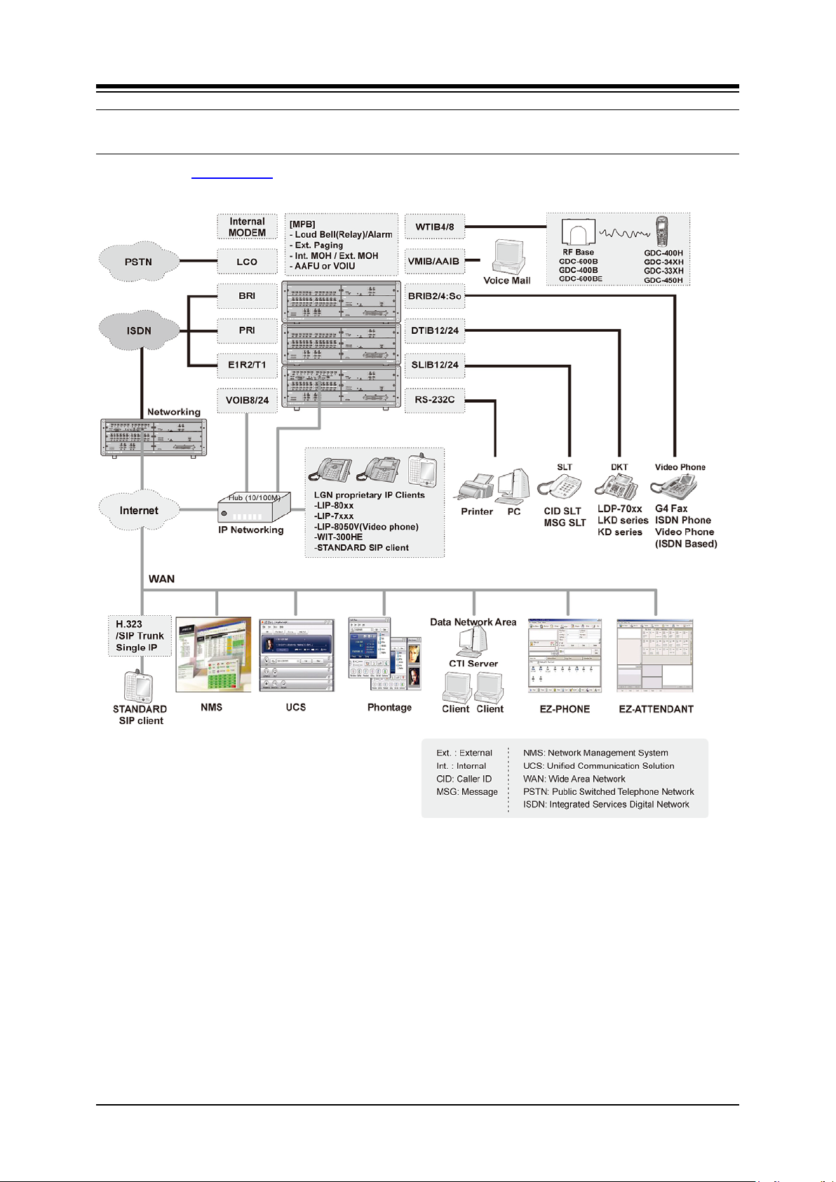
The following Figure 2.2-1 System Connection Diagram shows the components that make up
the iPECS-MG solution:
Figure 2.2-1 System Connection Diagram
5
Page 16

iPECS-MG
Hardware Description and Installation Manual Issue 1.1
2.3 System Component s
ITEM OPTION
BOARD
BKSU Basic KSU
EKSU Expansion KSU
PSU Power Supply Unit (350W)
Main Board MPB100 Main Processor Board 100 w/6 DKT, 6 SLT
MODU Modem Unit
MPB300 Main Processor Board 300 w/6 DKT, 6 SLT
MODU Modem Unit
Trunk Boards LCOB4 CMU4 4 LCO Interface Board
LCOB8 CMU8 8 LCO Interface Board
LCOB12 CMU12 12 LCO Interface Board
E1/PRIB Digital CO Interface Board (1 PRI or 1 E1R2)
Extension
Boards
Function
Boards
DETC GDC-600B
SLIB12 12 SLT Interface Board
SLIB12C 12 SLT Interface Board (RJ21)
SLIB24 24 SLT Interface Board
SLIB24C 24 SLT Interface Board (RJ21)
DTIB12 12 DKT Inter face Board
DTIB12C 12 DKT Interface Board (RJ21)
DTIB24 24 DKT Inter face Board
DTIB24C 24 DKT Interface Board (RJ21)
WTIB Voice Mail Interface Board (8 channels, 100 hrs)
AAIB Auto Attendant Interface Board (8 channels)
VOIB8 8 channel VoIP Interface Board
VOIB24 24 channel VoIP Interface Boar d
DECT Base Station (6 channels per Base)
GDC-600BE
WTIB4 4 channel DECT Wireless Terminal Interface Board
WTIB8 8 channel DECT Wireless T erminal Interfac e Board
WMK Wall Mount Bracket
DESCRIPTION
6
Page 17

iPECS-MG
Hardware Description and Installation Manual Issue 1.1
2.4 General Specifications
2.4.1 Dimension and Weight
ITEM HEIGHT (mm) WIDTH (mm) DEPTH (mm) WEIGHT (kg)
BKSU 170.2 440 325.4 6.2
EKSU 170.2 440 325.4 6.25
Digital Keyset* 268 203 124 0.9
Digital DSS/DLS Console 154 175 111 0.4
Digital ICM/Door Box 32 132 99 0.5
Digital Data Module 37 175 148 1.5
Base Station (600B/ 600BE) 170 220 57 0.46
GDC–33xH 145 50 35 0.15
Wireless
Terminal
GDC–34xH 131 49 32 0.102
GDC–4xxH 133 44 20 0.92
* Digital Keyset: LDP-7024D, Digital DSS: LDP–7048DSS, Digital Door Box: LDP-DPB
2.4.2 Environment
ITEM DEGREES (°C) DEGREES (°F)
Operation Temperature 0–40 32–104
Optimum Operation Temperature 20–26 68–78
Storage Temperature 10–70 32–158
Relative Humidity 0–80% non–condensing
2.4.3 System Electrical
ITEM SPECIFICATION (PSU)
1. Power Supply
– AC Voltage Input 100–240 Volt AC @47–63Hz
– AC Power 350W
– AC Input Fuse 6.3A @ 250Volt AC
– DC Output Voltage + 5, + 30Volt DC
2. Battery Backup
–PSU Input Voltage 24Volt DC
–PSU Battery Fuse 15.0A @250Volt AC
–Charging Current Max. 1A
7
Page 18

iPECS-MG
Hardware Description and Installation Manual Issue 1.1
2.4.4 PSU Fan
ITEM SPECIFICATION
Maker / part number POWERLOGIC / PLA07015B05H
Dimensions 70 X 70 X 15 (mm)
Rated voltage +5V
2.4.5 DECT Base Station (GDC-400B/GDC-600B/GDC-600BE)
ITEM SPECIFICATION
Power feeding +30V DC
Transmission Max. Power 250mW
Access Method/Duplex TDMA/TDD
Frequency Band 1, 880–1, 900MHz
Channel Spacing 1.728MHz
Modulation GFSK
Data rate 1.152Mbps
Max. Base Station distance from the WTIB 600m (twisted 2–pair cable)
2.4.6 Station Distance from the System
ITEM 22 AWG Wire (m/kft) 24 AWG Wire (m/kft)
Digital Keyset 500 / 1.6 330 / 1
Single Line Telephone 7, 500 / 24.6 5, 000 / 16.5
8
Page 19

iPECS-MG
Hardware Description and Installation Manual Issue 1.1
2.4.7 CO Loop
ITEM SPECIFICATION
Ring Detect Sensitivity 30Vrms @20–50Hz
DTMF Dialing
Frequency Deviation Less than +/– 1.8 %
Signal Rise Time Max. 5ms
Tone Duration, on time Min. 50ms
Inter–digit Time Min. 30ms
Pulse Dialing
Pulse Rate 10 pps
Break/Make Ratio 60/40%, 66/33% or 50/50%
2.4.8 Wireless DECT Terminal
ITEM SPECIFICATION
Max. Transmission Power 250mW
Modulation Method GFSK
Frequency Band 1, 880MHz–1, 900MHz
2.4.9 MPB VOIP
ITEM SPECIFICATION
LAN Interface 10 / 100 Base–T Ethernet (IEEE 802.3)
Speed 10 Mbps or 100 Mbps (Auto–Negotiation)
Duplex Half Duplex or Full Duplex (Auto–Negotiation)
VoIP Protocol SIP (RFC3261) and H.323 Revision 2
Voice Compression G.711/G.729/G.723.1
Voice/Fax Switching T.38
Echo cancellation G.168
9
Page 20

iPECS-MG
Hardware Description and Installation Manual Issue 1.1
2.4.10 VOIP channels (VOIB)
ITEM SPECIFICATION
LAN Interface 10 / 100 Base–T Ethernet (IEEE 802.3)
Speed 10 Mbps or 100 Mbps (Auto–Negotiation)
Duplex Half Duplex or Full Duplex (Auto–Negotiation)
VoIP Protocol SIP (RFC3261) and H.323 Revision 2
Voice Compression G.711/G.729/G.723.1
Voice/Fax Switching T.38
Echo cancellation G.168
2.4.11 Other System Specifications
ITEM DESCRIPTION SPECIFICATION
CPU M82805G, ARM9 Dual core (32bit, 375MHz)
Switching Device ACT2, Custom Mixed–Signal ASIC Device
Memory Back–up Duration 7years
Ring Signal 70Vrms, 25Hz
External Relay Contact 1A @30Volt DC
External Music Port 0dBm @600ohm
External Paging Port 0dBm @600ohm
MODU Analog Modem Bell, ITU–T, V.34 V.32BIS, V.90
Speed 300bps up to 33Kbps speed rat e
Connection Automatic rate negotiation
USB Version USB 1.1 compliant
Speed Max. 12Mbps
Mode Host Mode (Memory stick) only
10
Page 21

iPECS-MG
Hardware Description and Installation Manual Issue 1.1
2.5 System Capacity
DESCRIPTION CAPACITY/BOARD TOTAL
Time Slots 144 per KSU, Total Max. 432
Max. Ports 200 (MPB100), 414 (MPB300)
CO Line Ports 80 (MPB100) , 240 (MPB300)
Max. Direct Station (DKT, SLT,
DSS, So) Connections
LAN Port 1/MPB, 1/VOIB8, VOIB24
MODEM Channel 1/MODU 1
Attendant Positions 5/Tenant
Tenant Group 5 (MPB100), 9 (MPB300)
Intercom Links Non–Blocking
Paging
– All Call
– Internal
Station Speed Dial 50 (32 digits) / Station
System Speed Dial 1000 (32 digits) (MPB100)
Call Log
(Outgoing/Incoming/Missed Call)
CO Line Group 24 (MPB100)
Station Group 20 (50 members/group, MPB100)
Conference 3–13 Party All ports are available
Multi–Conference 3–13 Party Max. 3 groups / 13 party
Internal MOH (13 Music Resources) 1/MPB 1
External MOH 1/MPB 1
External Paging port 1/MPB 1
External Relay Contact 1/MPB 1
Alarm Input 1/MPB 1
RS–232C Port 1/MPB, 1/IPP Board 1
USB Port 1/MPB, 1/VMIB, AAIB 1 Host mode (Memor y stick) only
CPT/CID/ CO DTMF Detection
channels
PFT Circuit 1/LCOB4, LCOB8, LCOB12
120 (MPB100), 324 (MPB300)
1
1/VMIB, AAIB
1 zone
15 zones (MPB100)
30 zones (MPB300)
2000 (32 digits) (MPB300)
100 (32 digits)
(Not Protected)
72 (MPB300)
50 (50 members/group, MPB300)
32 channels (MPB100),
64 channels (MPB300)
32 channels (MPB100),
64 channels (MPB300)
11
Page 22

iPECS-MG
Hardware Description and Installation Manual Issue 1.1
2.5.1 System Maximum Call Capacity
iPECS-MG,
MPB100
SO DKTU/SLT PRI BRI CO IP
1st KSU 40 102*1 80 40 60 80
Total 108 80
1st KSU + 2nd KSU 88 120 80 80 80 80
Total 120 80
EXTENSION TRUNK
*1 DSIU DKT 6 + DTIB24, 4ea
− Max. DECT Terminal registration : 96
− Max. IP Phone registration : 120
− Max. VMIB or AAIB : 2each
− Max. WTIB : 2each
MAXIMUM PORT
120
200
iPECS-MG,
MPB300
SO DKTU/SLT PRI BRI CO IP
1st KSU 40 102*1 120 40 60 120
Total 108*2 120
1st KSU + 2nd KSU 88 198 180 88 132 180
Total 216 180
1st + 2nd + 3rd KSU 136 294 240 136 204 240
Total 324 240
EXTENSION TRUNK
MAXIMUM PORT
138
276
414
12
Page 23

iPECS-MG
Hardware Description and Installation Manual Issue 1.1
*1 DSIU DKT/SLT 6 + (4) DTIB24/SLIB24
*2 DSIU DKT 6 + DSIU SLT 6 + (4) DTIB24/SLIB24
− Max. DECT Terminal registration : 192
− Max. IP Phone registration : 324
− Max. VMIB or AAIB : 3each
− Max. WTIB : 3ea
− Max. WTIB: 3 each, when installing more than one WTIB4/8, install all WTIB4/8 in
the same KSU
− If installed ports exceed capacity, the attendant keyset receives an alarm.
Table 2.5.1-1 Simplified Maximum Port Chart
Boards Max. Extension Max. Trunk TOTAL
Total IP / TDM DECT
MPB100 120 120 96 80 200
MPB300 324 324 192 240 414
13
Page 24
iPECS-MG
Hardware Description and Installation Manual Issue 1.1
3. INSTALLATION OVERVIEW
3.1 General Installation Procedure
The basic steps to install an iPECS-MG are:
1. Locate the area for installing the system
2. Verify all equipment for the installation is on-site
3. Install the Basic and Expansion cabinets
4. Install the various boards in the cabinets
5. Wire the boards to the appropriate termination points
6. Wire and connect terminals
7. Initial power-up to default the database
8. Configure the system, see iPECS Feature and Admin Manuals
9. Verify the installation.
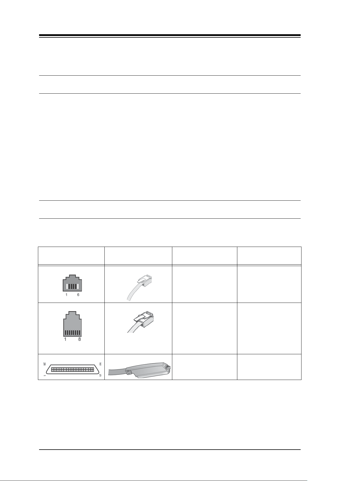
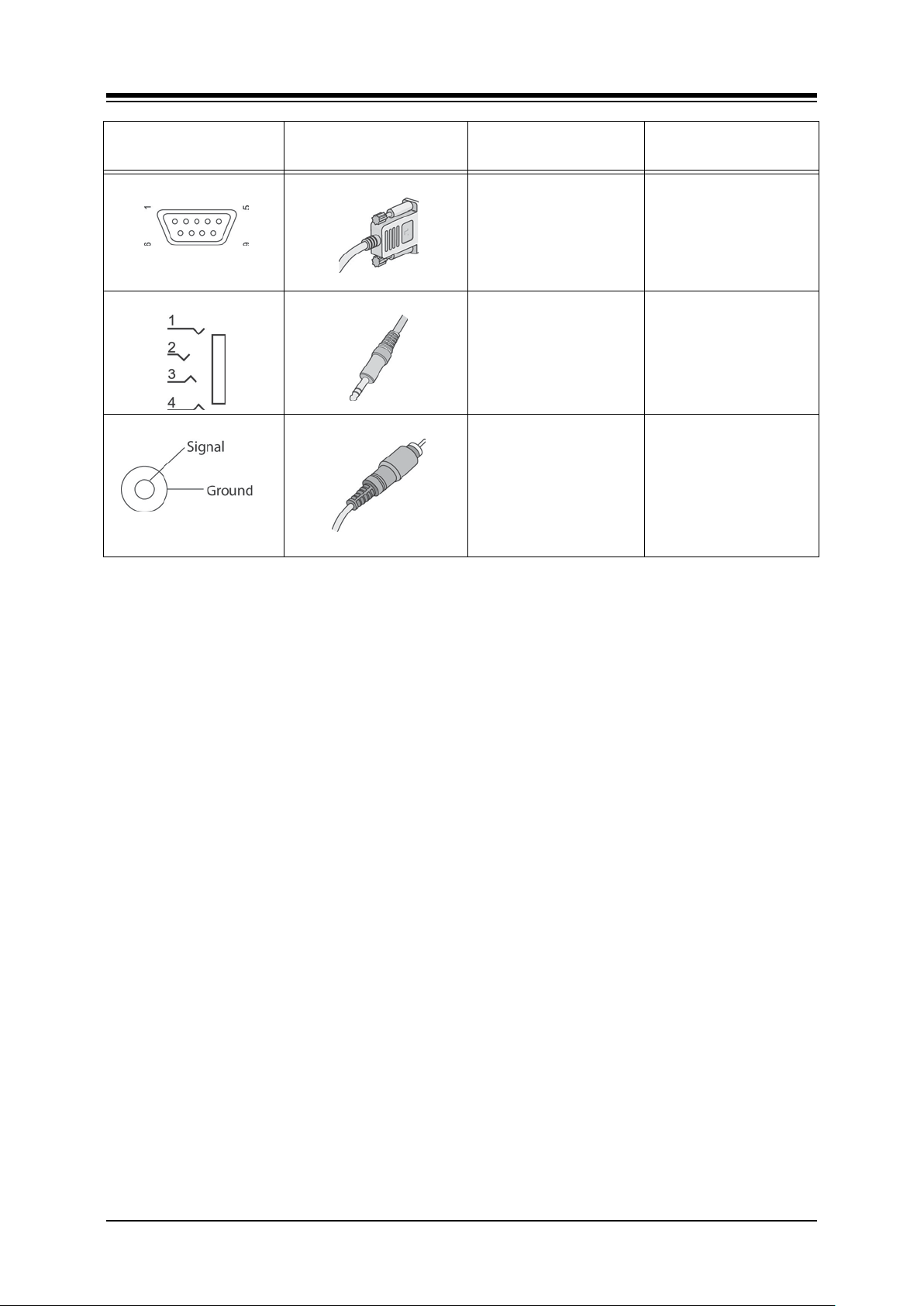
3.2 Types of Connectors
The following chart displays the various types of connectors employed with the iPECS-MG and
the various boards.
iPECS-MG
CONNECTOR TYPE
RJ11
RJ45
RJ21 (Female)
MATING-CONNECTOR BOARD PURPOSE
(Male)
MPB Relay and Alarm Port
MPB, VOIB8, VOIB24,
VMIB, AAIB, WTIB4,
WTIB8.
DSIU, DTIB12, DTIB24,
SLIB12,SLIB24
LCOB4, LCOB8, LCOB12
PRIB, BRIB4, BRIB8
DTIB12C, DTIB24C
SLIB12C, SLIB24C
LAN Port
Telephony Ports
DKT Ports
SL T Ports
LCO Ports
ISDN channels
DKT Ports
SL T Ports
14
Page 25
iPECS-MG
Hardware Description and Installation Manual Issue 1.1
iPECS-MG
CONNECTOR TYPE
RS–232C
Serial to Audio Ja ck
Audio Jack
MATING-CONNECTOR BOARD PURPOSE
MPB Serial Port
VOIB8, VOIB24, VMIB,
AAIB PRIB, BRIB2,
BRIB4, WTIB4, WTIB8
MPB EXT MOH Port
Serial Port
EXT PAGE Port
15
Page 26

iPECS-MG
Hardware Description and Installation Manual Issue 1.1
3.3 Installation and Safety Precautions
Please read the following guidelines concerning installation and wiring before installing the
iPECS-MG System. Also, be sure to comply with applicable local regulations.
When installing the telephone wiring, basic safety precautions should always be followed to
reduce the risk of fire, electric shock, and personal injury, including the following:
Never install the telephone wiring during a lightning storm.
Never install the telephone jack in wet locations unless the jack is specifically
designed for wet locations.
Never touch un-insulated telephone wires or terminals unless the telephone line has
been disconnected at the network interface.
Use caution when installing or modifying telephone lines.
Anti-static precautions should be taken during installation.
The iPECS-MG System is designed for wall mounting or a freestanding rack. Avoid installing
in the following places:
In direct sunlight and extremely hot, cold, or humid places (optimal temperature
range = 0o to 40oC).
Places where shocks or vibrations are frequent or strong.
Dusty places or places where the System may encounter water or oil.
Near high frequency generating devices such as sewing machines or electric
welding machines.
On or near computers, fax machines, or other office equipment, as well as
microwave ovens or air conditioners.
Do not obstruct the openings on the sides of the iPECS-MG System.
Do not stack up the Optional Service Boards.
Be sure to follow these precautions when wiring:
Do not wire the telephone cable in parallel with an AC power source, computer, fax
machine, etc. If the cables are run near such wires, shield the cables with metal
tubing or use shielded cables and ground the shields.
If the cables are run on the floor, use protectors to prevent the wires from being
damaged by foot traffic. Avoid wiring under carpets.
Do not use the same power supply outlet for computers, fax machine, and other
office equipment to avoid inducing RF noise into the iPECS-MG system.
The power and battery switches must be OFF during wiring. After wiring is
completed, the power switch may be turned ON.
If an extension does not operate properly, disconnect the telephone from the
extension line and then re-connect, or turn the System power OFF and then ON
again.
Use unshielded twisted pair cable for connecting CO lines and stations.
16
Page 27
iPECS-MG
Hardware Description and Installation Manual Issue 1.1
4. KSU INSTALLATION
4.1 BKSU Unpacking
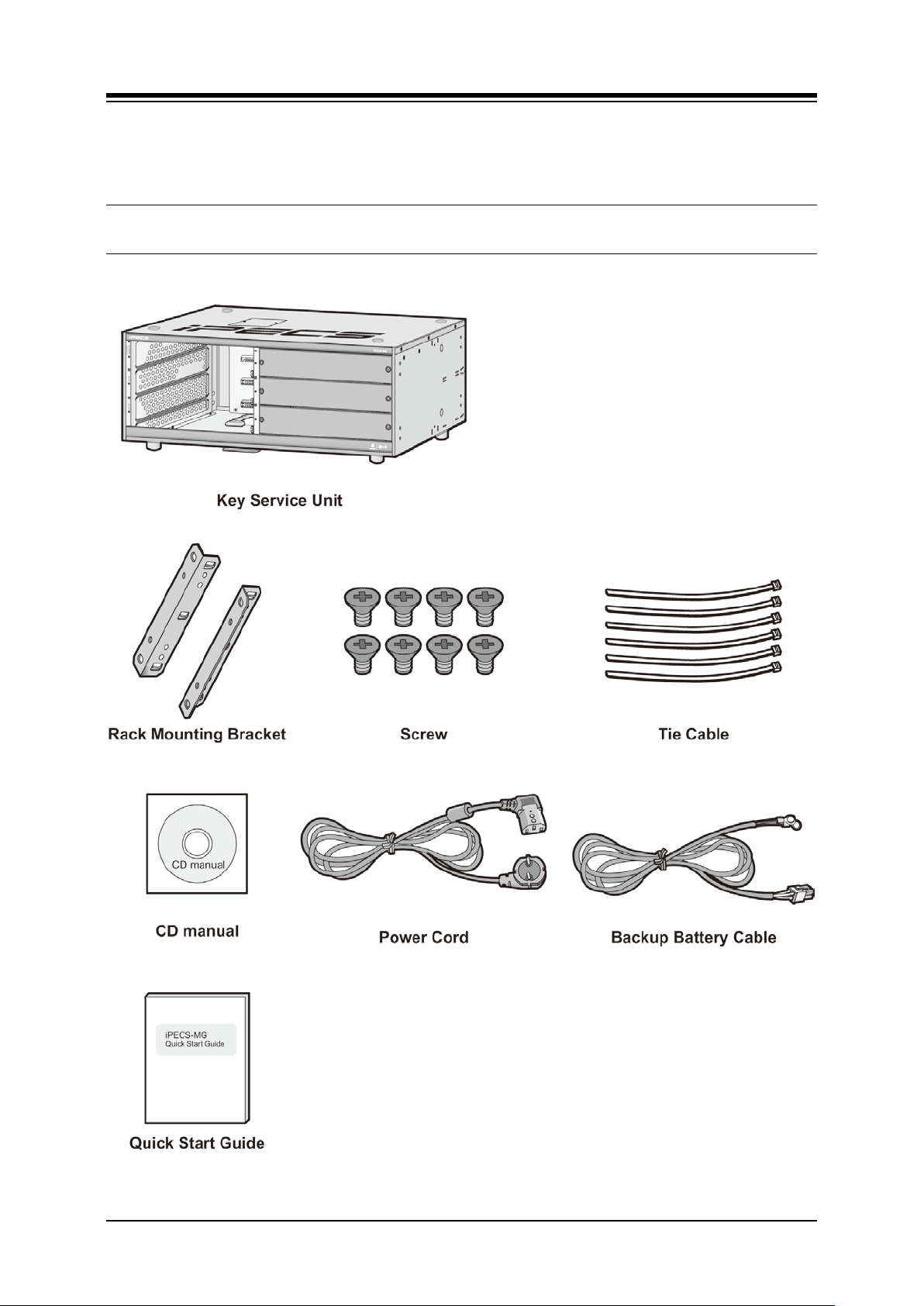
Open the box and verify the items shown in Figure 4.1-1 BKSU Carton Contents are included:
Figure 4.1-1 BKSU Carton Contents
17
Page 28
iPECS-MG
Hardware Description and Installation Manual Issue 1.1
4.2 EKSU Unpacking
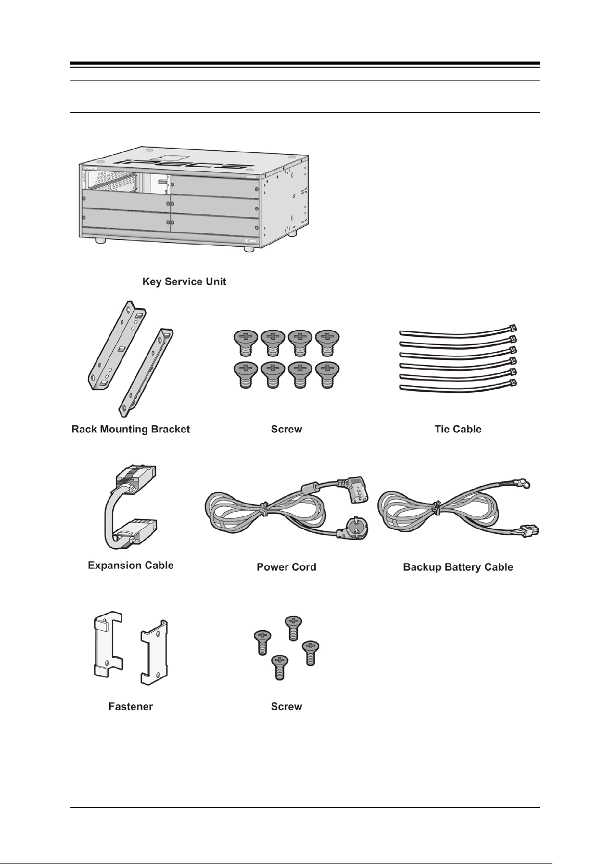
Open the box and verify the items shown in Figure 4.2-1 EKSU Carton Contents are included:
Figure 4.2-1 EKSU Carton Contents
18
Page 29
iPECS-MG
Hardware Description and Installation Manual Issue 1.1
4.3 KSU Diagram, Exterior and Dimension
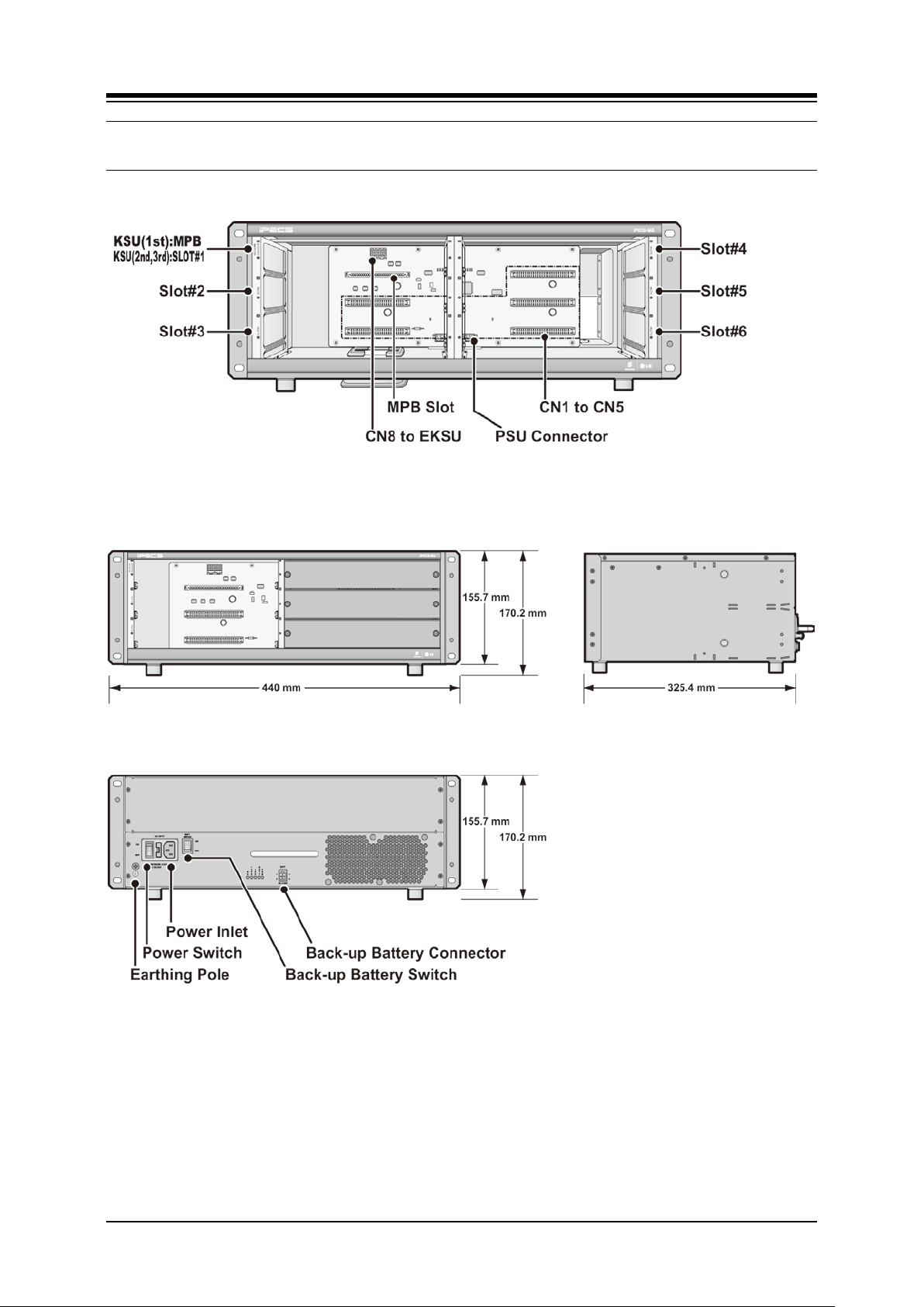
For reference purposes, Figure 4.3-1 shows the exterior and dimensions of the KSU.
Figure 4.3-1 KSU Exterior and Dimension
19
Page 30
iPECS-MG
Hardware Description and Installation Manual Issue 1.1
4.4 Basic KSU Mounting
The KSU can be 19” rack or wall mounted.
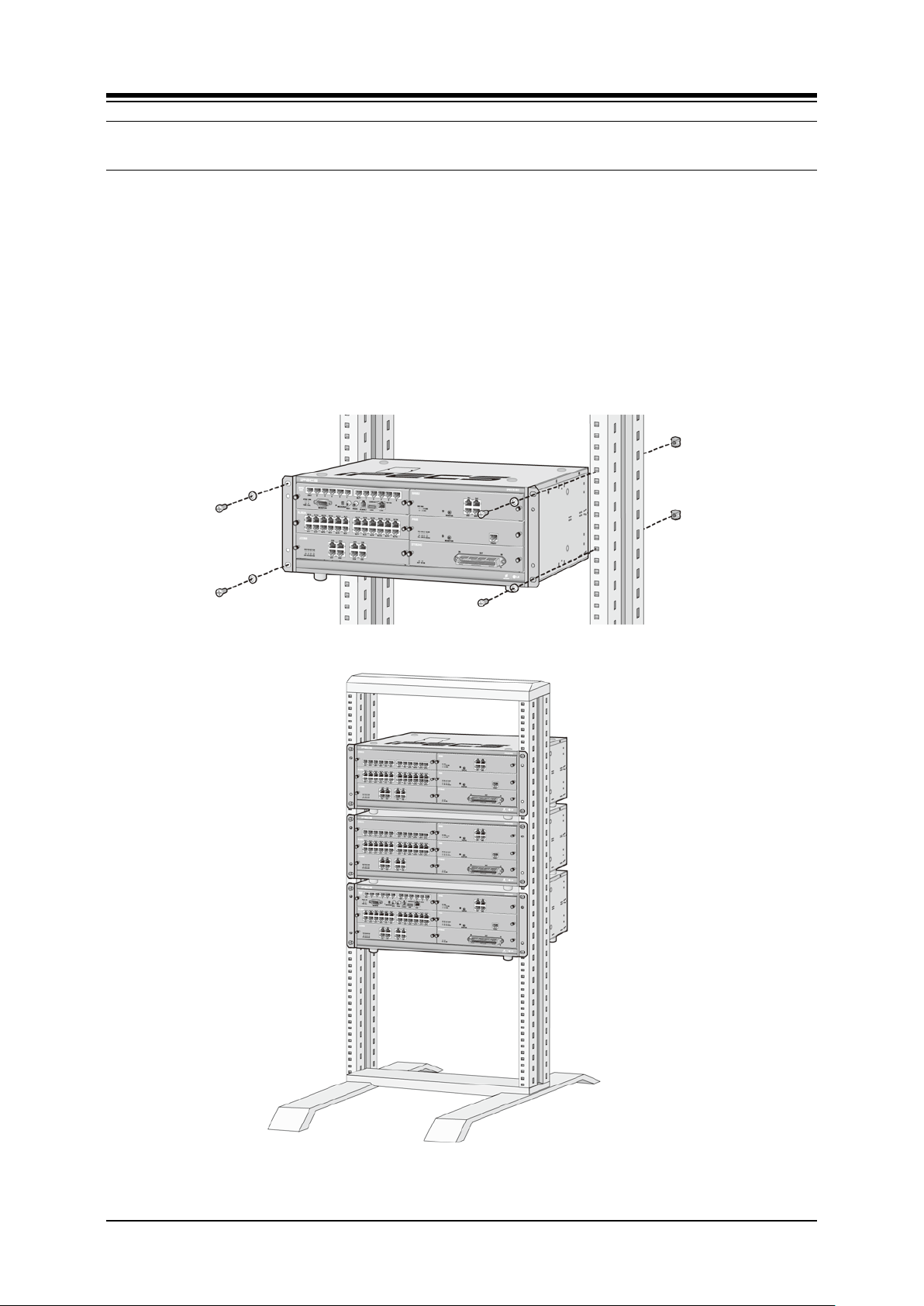
4.4.1 Rack Mounting
1. Install the Rack Mount brackets to each side of the KSU with the eight (8) screws
provided.
2. Insert screws with washers through the Rack Mount bracket flange on each side of
the cabinet.
3. As required, thread screws into nuts, or directly into threaded holes in the rack
4. Tighten the screws securely to complete the rack mounting. These screws are
supplied with the rack.
Figure 4.4.1-1 Rack Mounting
20
Page 31

iPECS-MG
Hardware Description and Installation Manual Issue 1.1
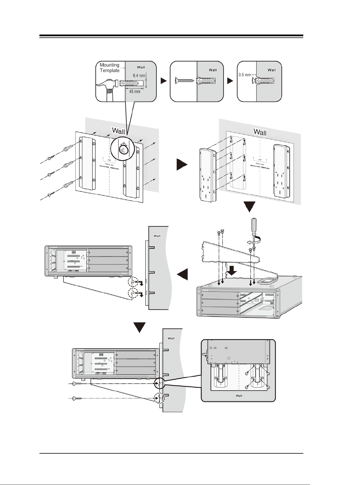
4.4.2 Wall Mounting
1. Attach the included mounting template for accurate placement to the wall, level, and
drill 12 holes.
2. Install 12 anchor plugs into the wall using the mounting template (Figure 4.4.2 1 Wall
Mounting).
3. Insert 12 included screws into the 12 anchor plugs.
4. Tighten the screws leaving about 5 mm (0.2 inches) exposed
5. Hook the Wall Bracket onto installed screws and tighten screws.
6. Install the Rack Mount brackets to each side of the KSU with the eight (8) screws
provided.
7. Attach the Wall Shelf brackets to the bottom of KSU and affix using the eight (8)
screws provided.
8. Hook the Wall Shelf brackets onto the Wall Bracket, making sure that the System
slides down securely.
9. Affix the Wall Shelf brackets to the Wall Bracket using the four (4) screws provided.
21
Page 32
iPECS-MG
Hardware Description and Installation Manual Issue 1.1
Figure 4.4.2-1 Wall Mounting
22
Page 33

iPECS-MG
Hardware Description and Installation Manual Issue 1.1
4.5 Expansion KSU Installation
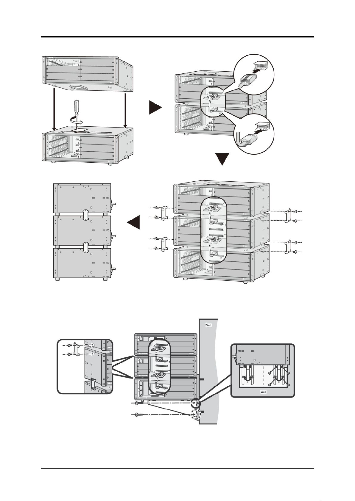
The Expansion KSU is installed on top of the Basic KSU. Fasteners are installed on each side
of the KSUs to maintain a stable mechanical connection. The Expansion cable is installed to
connect the KSU backplane signaling and media (voice) paths. Use the following instructions
and Figure below to install.
1. Remove the Expansion Cable Cover Plates on the top of the BKSU and bottom of the
EKSU. Remove the two screws holding the Cover plate and remove the Cover plate.
2. Install the Rack Mounting brackets on the EKSU with the screws provided.
3. For Wall Mounting
Place the EKSU on top of the BKSU, making sure to align the feet of the EKSU with
the cavities in the lower KSU.
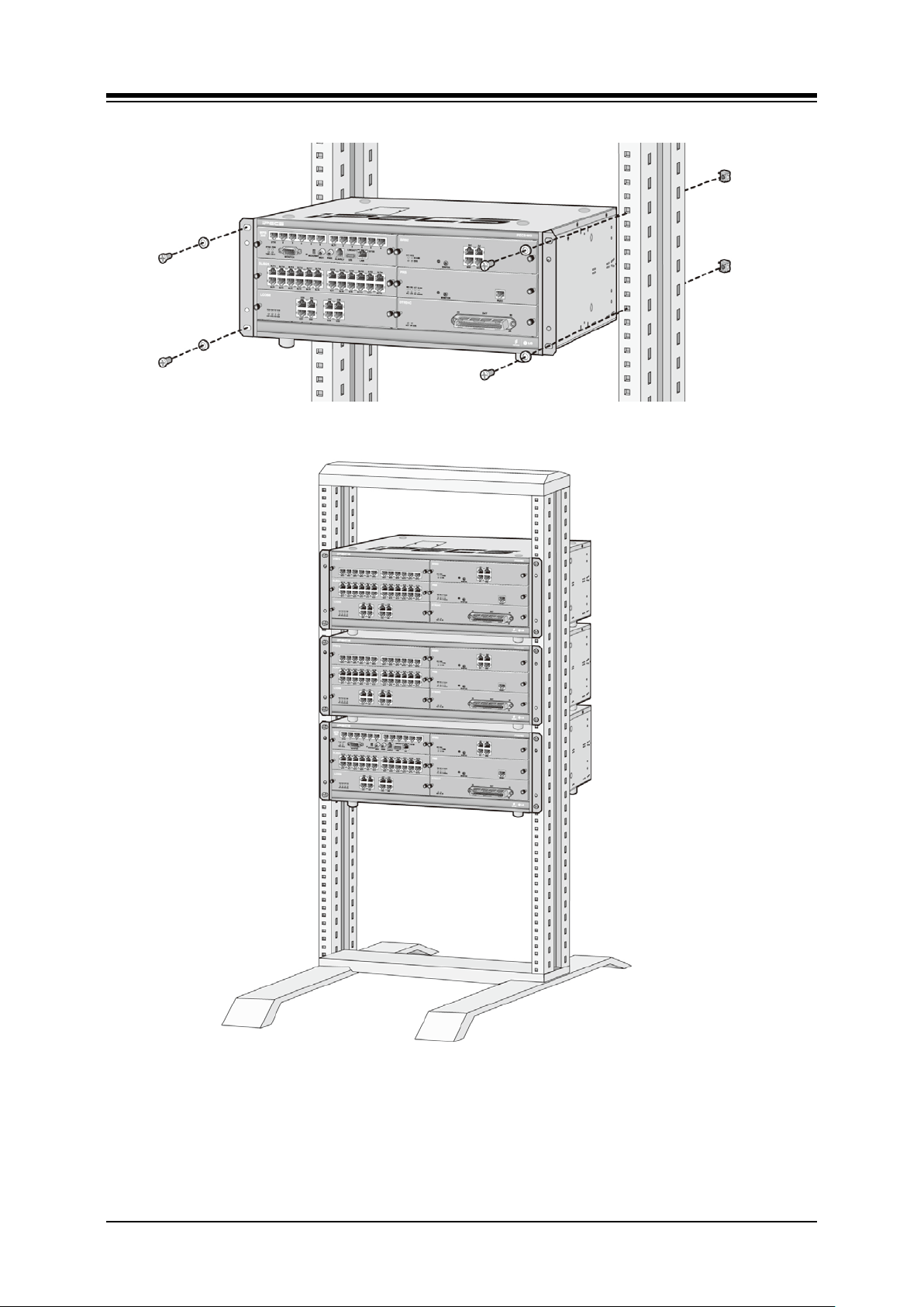
For 19” Rack mounting,
Insert screws and washers through the Rack Mounting bracket on each side of the
cabinet.
If required, thread screws into nuts, or directly into threaded holes in the 19” rack and
tighten screws securely.
4. Install the Fasteners on each side of the cabinets using the screws provided with the
EKSU.
5. Install the Expansion cable between the two cabinets. Attach one connector to the
C8 mating connector in the lower KSU and the other end to C9 in the upper KSU. It
may be necessary to remove the blank Slot cover plates from the front of the KSUs.
CAUTION
Be careful not to bend the pins of Expansion Cable connectors.
If the site requires a second EKSU, install and connect the second EKSU to the first EKSU as
described above.
23
Page 34
iPECS-MG
Hardware Description and Installation Manual Issue 1.1
C9 connector
C8 connector
Figure 4.5-1 Expansion KSU installation
Figure4.5-2 Expansion KSU Wall Mounting
24
Page 35
iPECS-MG
Hardware Description and Installation Manual Issue 1.1
Figure 4.5-3 Expansion KSU Rack Mounting
25
Page 36
iPECS-MG
Hardware Description and Installation Manual Issue 1.1
4.6 Power Supply Unit Wiring
Each KSU is equipped with a Power Supply Unit (PSU) that converts AC power to the DC
voltages required by the system. The DC voltages are distributed to the various boards in the
cabinet by the backplane wiring under control of the MPB. For PSU specifications see section
2.4.3.
The PSU in each cabinet should be connected to a common Earth or Frame ground and, if
Battery Back-up operation is required, each PSU should be connected to a Battery Back-up
circuit. Each PSU also requires a separate connection to AC power.
NOTE
Proper Power-up and down sequence
Turn off the PSU in the EKSU(s) then turn off the PSU in the BKSU. If the PSU in the
BKSU is turned off first, the system will automatically remove power from the EKSU.
The 1st and 2nd KSUs will work independent of the 3rd KSU (power shut-Off).
The 1st KSU will work independent of the 2nd KSU (powered-Off); however, the 3rd
KSU cannot work without the 2nd KSU powered-On.
It is recommended that the iPECS-MG be reset if the PSU in an EKSU is power cycled
or turned OFF.
4.6.1 Frame Ground Connection
Proper grounding minimizes the affect of power induced and RF noise, and reduces the risk of
damage or injury in case of a power cross or lightning strike. Be sure to comply with applicable
local regulations regarding grounding of equipment. To ground the system, at each KSU,
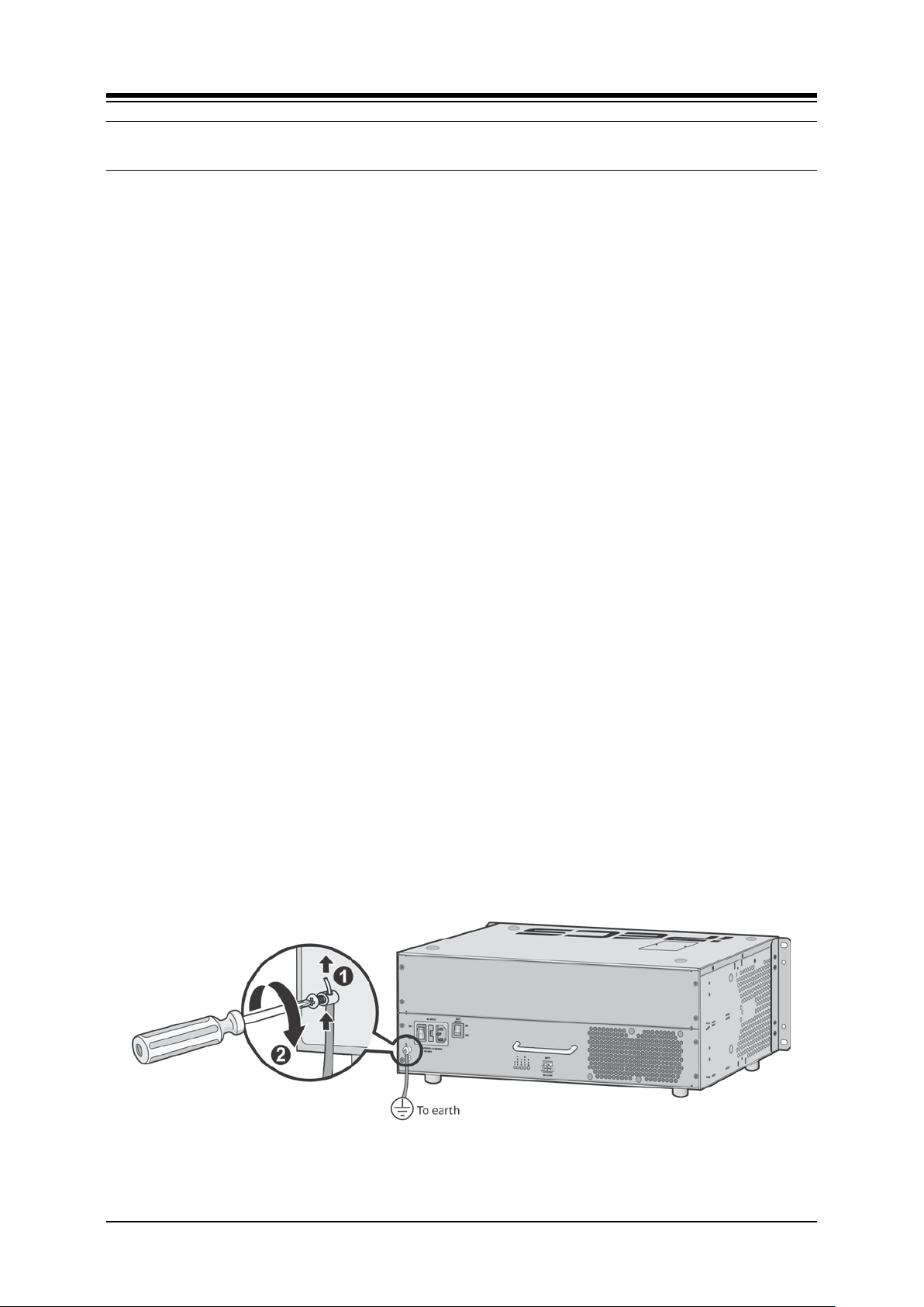
1. Assure the system is not connected to AC power.
2. Loosen the Ground lug screw by turning the screw counter-clockwise to loosen, as
shown in Figure 4.6.1-1.
3. Strip approximately 15mm (1/2 inch) of insulation from the end of the ground wire. A
UL1015 AWG #18 (1.0mm) green/yellow insulated copper wire should be used with a
recommended length of 1 meter (3.28 feet) or less.
4. Insert the grounding wire in the ground lug and tighten the screw.
5. Then connect the grounding wire to an appropriate ground source. A cold water pipe
with no insulated joints is often an acceptable ground.
Figure 4.6.1-1 Grounding the KSU
26
Page 37
iPECS-MG
Hardware Description and Installation Manual Issue 1.1
4.6.2 External Backup Battery Installation
In case of power failure, the external backup batteries automatically maintain uninterrupted
power for the iPECS-MG System. The external batteries must provide 24V DC; this is
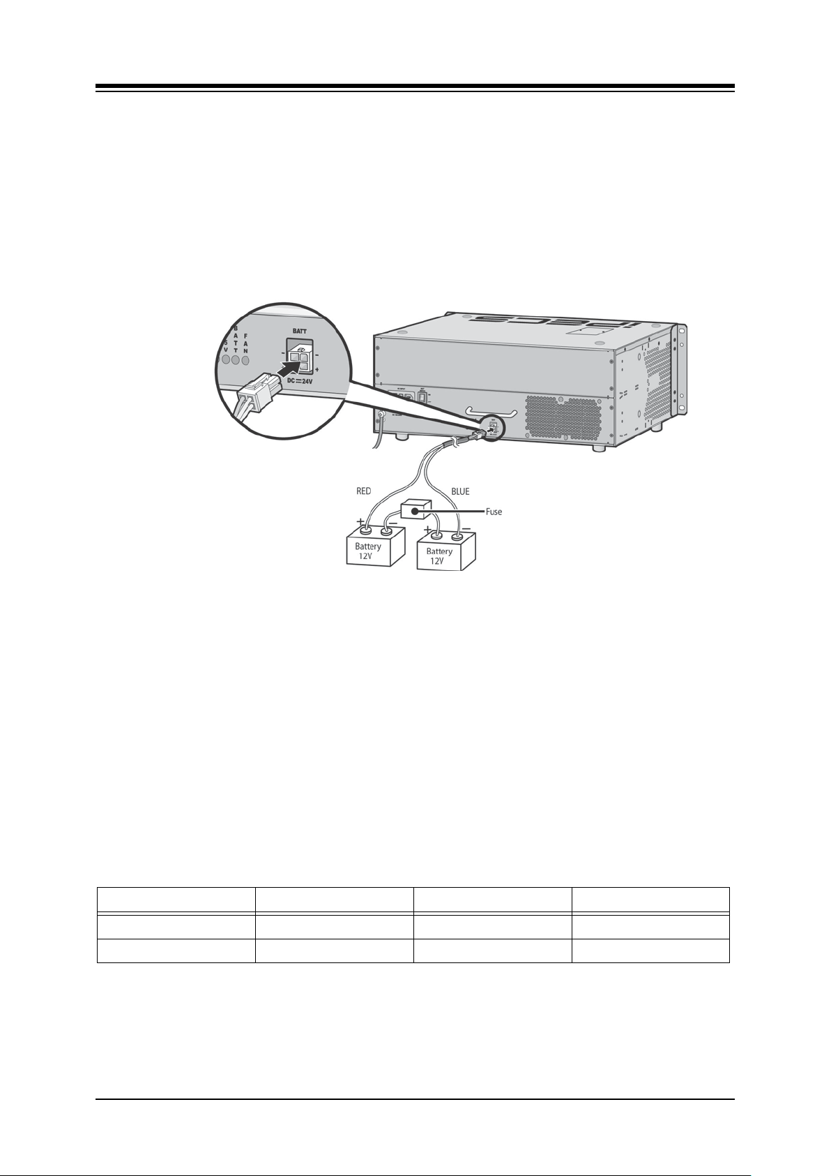
generally accomplished by connecting two 12V batteries in a series arrangement as shown:
connect the backup battery cable with 2 identical batteries. (12V DC)
insert a fuse between the batteries as shown.
connect the external back up battery cable to the battery connector of the PSU.
after connecting the external backup battery cable, turn on the battery switch.
Figure 4.6.2-1 External Backup Battery Installation
NOTE
the cable used to connect the battery is supplied with the KSU
Battery operation is controlled by the PSU. The PSU will provide charging current
to the batteries during normal AC power operation at a maximum of about 1 Amp.
PSU battery operation will be halted if the AC power is re-connected or if the
battery voltage is too low to maintain full-system operation.
The length of time that the System will operate on the batteries is dependent on
several elements including, battery charge, condition of the batteries, capacity of
the batteries, and the size of the system (number of station ports). The chart below
gives the approximate back-up times for several system sizes and different battery
capacities in ampere-hours.
Table 4.6.2-1 Battery Capacities
BATTERY CAPACITY DKT 24PORTS DKT 72 PORTS DKT 120 PORTS
20AH 6 hours 3 hours 1.5 hours
40AH 12 hours 6 hours 3 hours
27
Page 38

iPECS-MG
Hardware Description and Installation Manual Issue 1.1
CAUTION
It is recommended to use an external backup battery fuse between the battery and
the System.
The battery must supply 24 VDC with a recommended capacity of 20 Amp-hours.
Carefully check the battery polarity with cable colors (Red and Blue) when
connecting the battery to the System.
Do not short out the external batteries and cables.
There is a danger of explosion if external batteries are incorrectly replaced.
Replace only with the same or equivalent type recommended by the manufacturer.
Dispose of used batteries according to the manufacturer’s instructions.
4.6.3 Power Supply Unit Replac ement
The PSU, which is located at the rear of the KSU, converts AC power to the DC sources
required by the system. The PSU includes a replaceable fuse, 6.3 A @ 250V and cooling fans.
Each KSU comes equipped with a PSU that is field replaceable.
Table 4.6.3-1 PSU Capacity
PSU TYPE +5V DC +27V DC +30V DC
PSU (SMPS) 10.0A 1A (Battery charge) 10A
To remove the existing PSU
Remove four (4) screws that hold the PSU to the KSU by turning the screws
counter-clockwise.
Using the PSU handle pull the PSU from the KSU.
To install the new PSU
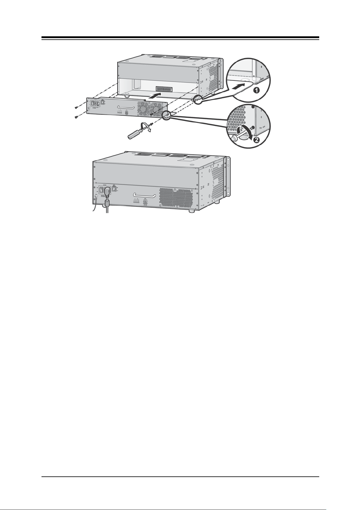
Insert the PSU along the guide rails on the rear side of iPECS-MG.
Slide PSU into the KSU to firmly seat the PSU in the backplane connector
To affix securely, insert and tighten four (4) screws as shown below.
28
Page 39
iPECS-MG
Hardware Description and Installation Manual Issue 1.1
Figure 4.6.3-1 PSU Installation
NOTE
Turn OFF the PSU in the EKSU(s) then turn OFF the PSU in the BKSU. If the PSU in
the BKSU is turned OFF first, the system will automatically remove power from the
EKSU.
The 1st and 2nd KSUs will work independent of the 3rd KSU (power shut OFF).
The 1st KSU will work independent of the 2nd KSU (powered OFF); however, the 3rd
KSU cannot work without the 2nd KSU powered-ON.
It is recommended that the iPECS-MG be reset if the PSU to an EKSU is power cycled
or turned OFF.
29
Page 40
iPECS-MG
Hardware Description and Installation Manual Issue 1.1
5. BOARD INSTALLATION
5.1 General Board Install Procedure
Prior to installing the Boards, the following should be considered:
CAUTION
Verify the electrical Power is turned OFF before installation of boards.
To protect the System from static electricity, do not directly touch the boards to
discharge static, touch a grounded object, or wear a grounding strap.
To install the Board,
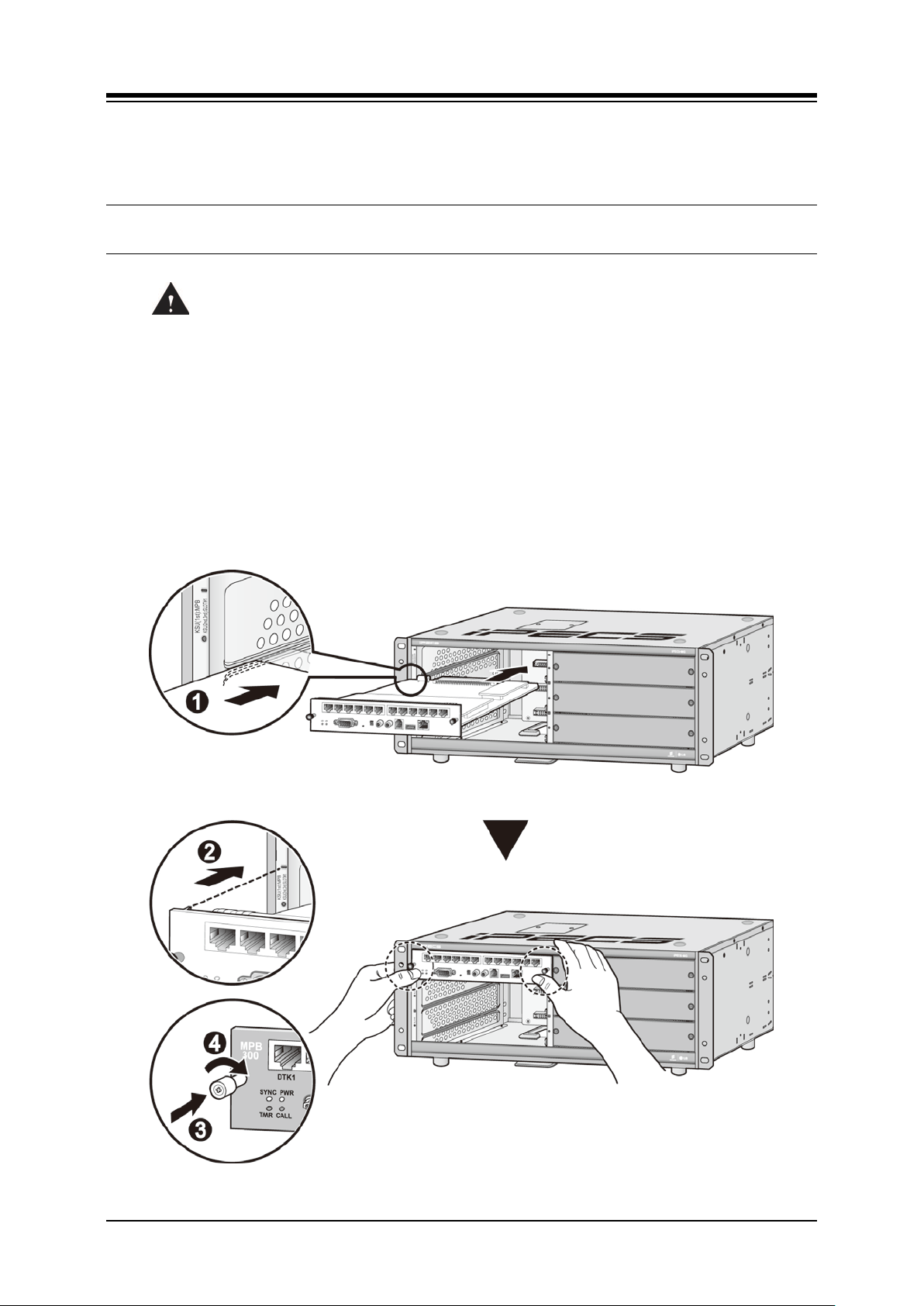
1. If required, install any option modules on the board and set any switches.
2. Slide the board along the guide rails into the KSU until the Board is securely seated in
the backplane connector.
3. Press the thumbscrews in, and turn clockwise to affix the Board securely.
4. Wire the Board connectors as required.
Figure 5.1-1 Board Installation
30
Page 41
iPECS-MG
Hardware Description and Installation Manual Issue 1.1
5.2 Main Processing Board
The Main Processor Board controls communication between the peripheral boards, supervises
all resources in the system, controls the gain adjustment of the PCM signal, generates the
System tones, maintains System audio prompts and manages System call processing. The
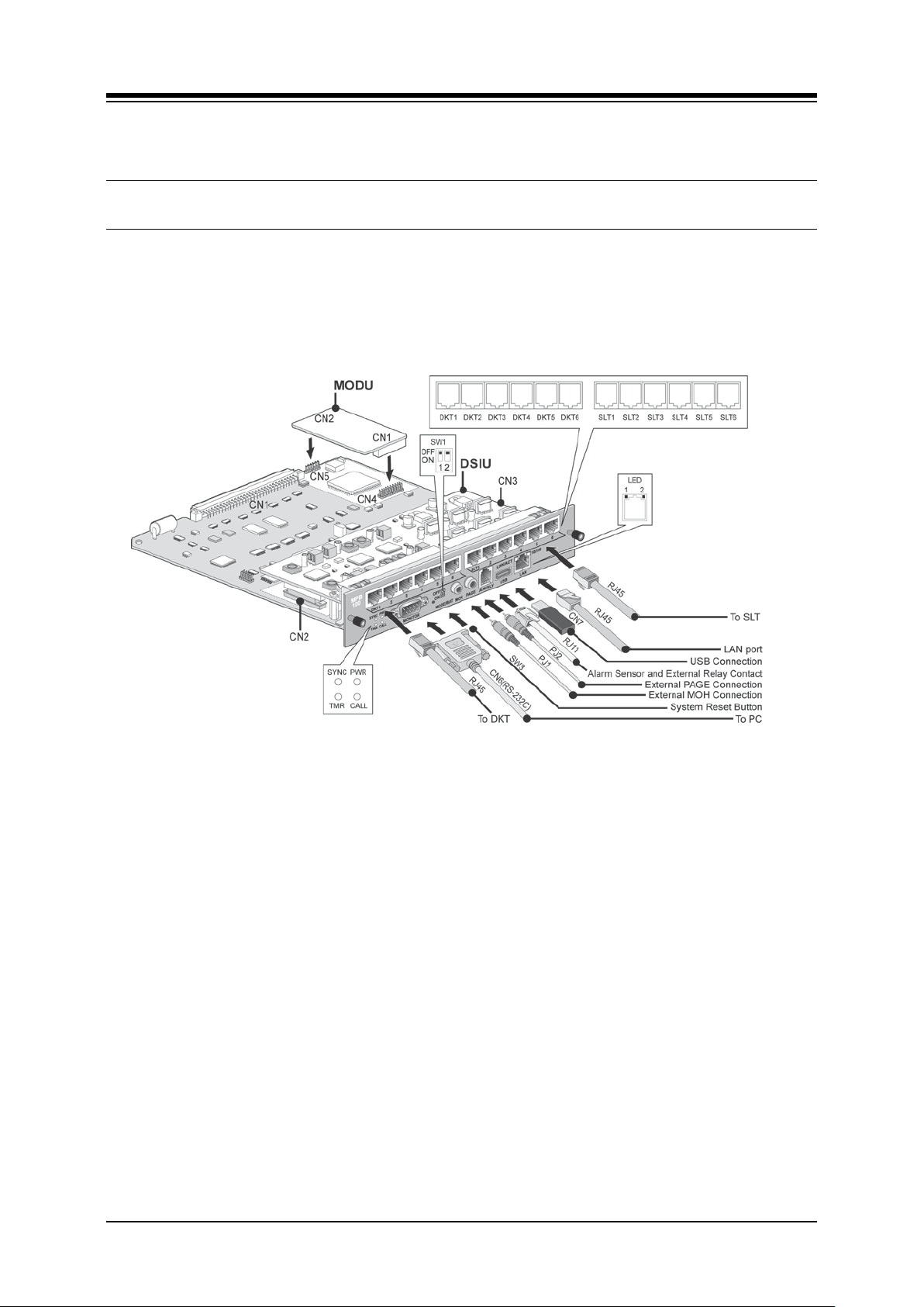
MPB (Figure 5.2 1) is the main control for the System, and is composed of the microprocessor
and memory, the PCM management and miscellaneous functional circuits.
The MPB must be installed in the MPB slot, the upper left (1st) slot of the BKSU.
Figure 5.2-1 MPB
If an MPB is not installed, DC Power (+5V, +30V) will not feed to the backplane and other
boards or EKSUs.
The following devices and functions are included on the MPB:
Main Processor: MINDSPEED ARM9 Dual Core, M82805G, 375MHz
PCM Voice Processing circuit (ACT2) - PCM voice switching, System Tone/Gain
Control
Tone (DTMF/CPT) Detection/CID Signal (FSK/DTMF/RCID) Detection/CID
Generation
Real Time Clock for System Time/Date
System Memory [SDRAM/SRAM/Flash ROM/NAND Flash]
PLL Circuit for ISDN Line Clock Synchronization
1 Internal MOH - 13 Music resources
System Prompt storage, 3 languages
Basic 4 AA Function (default) or 4 VoIP channel
MODU (Option) Interface
Basic DSIU Included 6 DKTs and 6 SLTs
31
Page 42

iPECS-MG
DTMF, CPT , CID Detection
Hardware Description and Installation Manual Issue 1.1
4 Status Indication LEDs
1 RS-232C serial port
1 Reset Button
1 Switch for Admin Database back up
1 External MOH port
1 External Paging port
1 Alarm Detection port
1 Relay Contact for general purpose
1 USB port for DB upload and download, SW upgrade with Memory stick
1 Ethernet port – System maintenance, SW upgrade, and basic 4 channel VoIP
Table 5.2-1 MPB 100 and MPB 300
ITEM MPB100 MPB300 REMARK
SRAM 2ea (4MB) 4ea (8MB) User Data back up
ACT2 32 DSP channels 64 DSP channels
channels
MAX Ports 200 414
Available MAX (Trunk +
Extension) Ports
NOTE
Except MAX Ports, RAM, and DSP channels, all functions of both MPB100 and
MPB300 are the same.
5.2.1 Switch and LED Functions
The MPB has various switches and LEDs (refer to the following table).
Table 5.2.1-1 Connector Jack and Switch Functions
SWITCH & CONNECTOR FUNCTIONS DESIGNATION
SW1-1 Database Protect MODE
SW1-2 Memory Battery BAT
SW2 System Reset
PJ1 (Red) External MOH Connection MOH
PJ2 (Blue) External PAGE Connection PAGE
MJ3 (RJ45)
MJ2 (RJ45) USB port USB
MJ1 (RJ45) LAN Port LAN
Alarm Sensor and External Relay
Contact
ALM/RLY
32
Page 43

iPECS-MG
Hardware Description and Installation Manual Issue 1.1
After all the boards are installed and wiring complete and before programming the System,
Switch 1-1 should be OFF and the system power turned ON to initialize the default System
database. Once the database has been initialized, Switch 1-1 should be placed in the ON
position to maintain the database and features programmed during Admin. Also, Switch 1-2
should be placed in the ON position, which connects the Lithium battery to protect the System
database and real-time clock from a power loss.
NOTE
The battery has a 10+ year life and should not require replacement during the life of the
System. If needed, replace the battery with the same or equivalent type recommended
by the manufacturer. The System will not function normally if the battery is incorrectly
replaced. Be sure to dispose of used batteries according to manufacturer instructions
and/or local government regulations.
Table 5.2.1-2 LED Indications
LED DESCRIPTION
LD1 (Blue), TMR Timer, Periodic Toggle — ON, 100msec; OFF, 100msec.
LD2 (Blue), CALL C all Task Status — ON, Call task activated; OFF, Call Task idle
LD3 (Blue), SYNC External ISDN board (PRI or BRI) Clock synchroniz ation
ON: PLL circuit activ ation by External C lock from IS DN Board, i PE CS -M G w ill be operated
based on external ISDN clock (refer to “NOT E” ).
OFF: PLL activation by I nternal C lock, iPEC S -MG will be operated based on internal clock.
LD4 (Blue), PWR Sy stem D C P ower ON Indication – ON, Power ON; OFF, Power OFF
NOTE
When several PRIB/BRIBs are installed, the default clock priority will be as follows
unless modified by the Admin (PGM301):
Boards – PRIB > BRIB2 or BRIB4 > Internal Clock
KSUs – 1’st KSU > 2’nd KSU > 3’rd KSU
Slot – Slot 1 > Slot 2 >…> Slot 18
Table 5.2.1-3 LAN Connector LED Indication
LED DESCRIPTION
1 (Green) Link Status LE D – ON: Link OK, OFF: No Link
2 (Orange) Speed Status LED – ON: 100Mbps, OFF: 10Mbps
33
Page 44
iPECS-MG
Hardware Description and Installation Manual Issue 1.1
5.2.2 Modem Unit Installation
Before installing the MPB, if required, the optional Modem Unit (MODU) must be installed. The
MODU is an analog modem supporting Bell, ITU-T, V.34, V.32BIS, V.90 Protocol at a baud rate
of 300bps to 33Kbps with automatic rate negotiation. The MODU provides a modem for
connection to the system database and maintenance functions. The MODU can be accessed
remotely over an analog CO line by calling the Modem CO line or Station. For additional
information on MODU set-up, see the iPECS-MG Admin Manual.
The MODU is installed on connectors CN4 and CN5 of the MPB as shown in Figure 5.2-1. Use
care to align pins of the CN4 and CN 5 connector with the CN1 and CN2 connectors on the
MODU and press firmly in place.
5.2.3 MPB Installation
Before installing the MPB, mount the optional MODU as described above. The MPB must be
installed in the MPB slot, the upper left slot of the BKSU.
Assure Power is OFF
Slide the MPB in the guide rails of the first slot (upper left) of the Basic KSU.
Tighten thumbscrews to hold the board firmly in place.
5.2.4 LAN Port Wiring
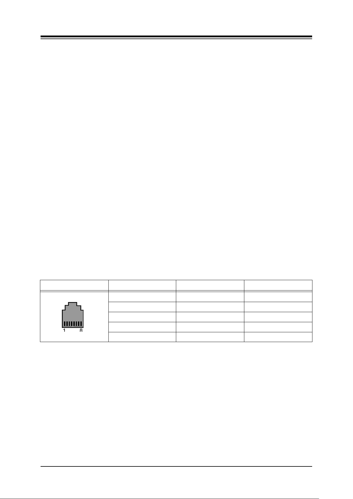
The LAN connector accesses the System Ethernet port (10/100 Base-T) for Web access to the
System database and maintenance functions as well as the basic 4 channel VoIP circuit, if
installed. The LAN connector pin-outs are shown in the chart below and should be wired to an
appropriate Ethernet switch port. Note that by reversing the TX and RX pins, the LAN
connector can be directly connected to a PC for Admin and maintenance purposes.
Table 5.2.4-1 LAN Port Connector
CONNECTOR PIN SIGNAL FUNCTION
RJ45 4,5,7,8 Not used
1 TX+ Transmit Data
2 TX- Transmit Data
3 RX- Receive Data
6 RX+ Receive Data
34
Page 45
iPECS-MG
Hardware Description and Installation Manual Issue 1.1
5.2.5 Connecting Miscellaneous Devices
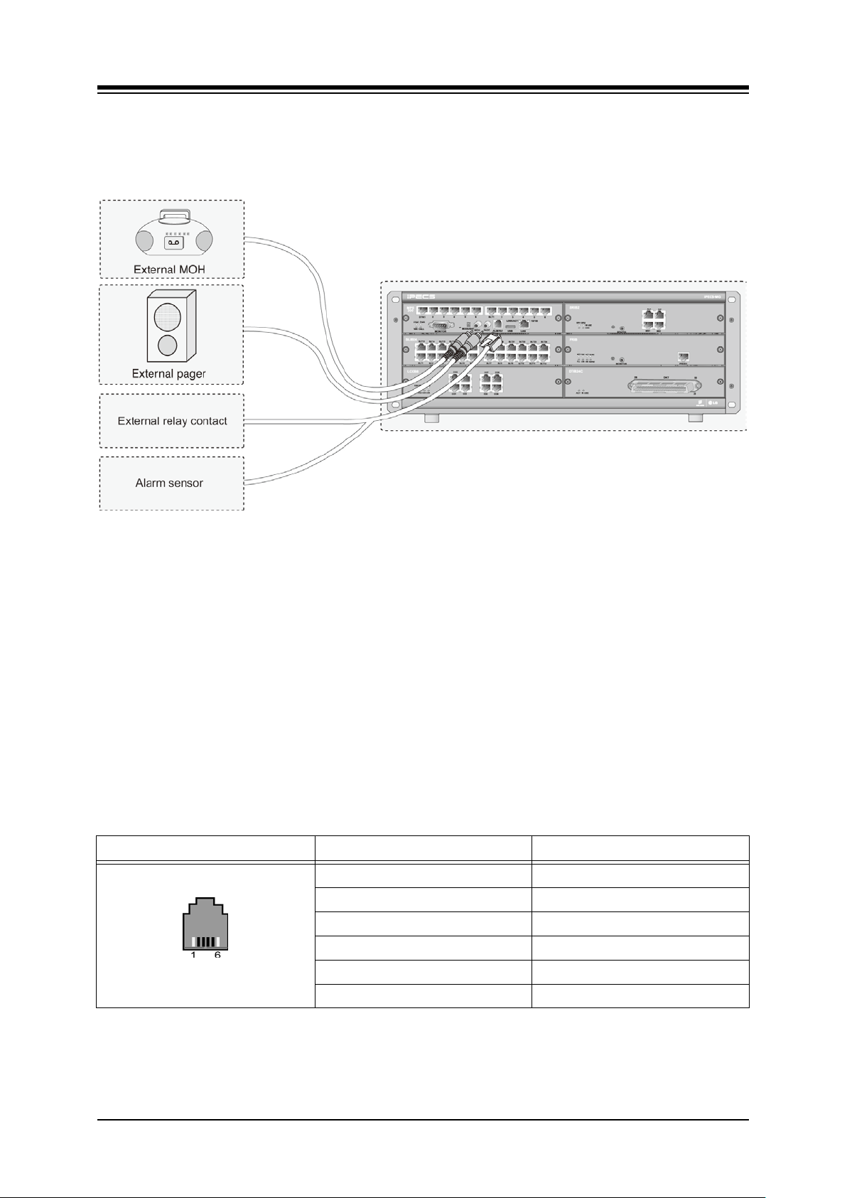
The MPB provides connections for an external music source, an external page port, a relay
contact, and an alarm detection input monitor.
Figure 5.2.5-1 Miscellaneous Connections
5.2.5.1 Alarm/Relay Wiring
The RJ-11 Alm/Rly connector provides access to the Remote Contact Monitoring circuitry and
an External Control Contact. The Contact Monitoring circuitry can be used to monitor an
external alarm or doorbell contact. The External Control Contact activates as a Loud Bell, a
Door Open control, or control for External paging equipment when External Paging is access.
Referring to Figure 5.2.5-1 and the pin-out chart below
Wire the Alarm Tip and Alarm Ring located on pins 2 and 3 of the RJ11 to the Alarm
contact termination point using UTP cable
Wire the External Control Contact located at pins 4 and 5 of the RJ11 to the external
device using UTP cable
Tag or number wiring for maintenance
Table 5.2.5.1-1 Alarm and Relay Contact Connector
CONNECTION PIN SIGNAL NAME
RJ11
1 Not used
2 ALARM-T
3 ALARM-R
4 Relay-T
5 Relay-R
6 Not used
35
Page 46
iPECS-MG
Hardware Description and Installation Manual Issue 1.1
5.2.5.2 Page Audio Connector Wiring
The Page connector allows paging audio to be sent to External Paging equipment. The system
will deliver audio as a 0-dBm signal into a 600-ohm load.
Referring to Figure 5.2.5-1,
Wire the Page Audio connector to the termination point of the audio input of the
External Page equipment.
Tag or number wiring for maintenance.
5.2.5.3 MOH Connector Wiring
When a call is placed on hold, MOH (Music on Hold) is presented to the caller. MOH can be
provided from an internal source or from an external audio source connected to the MOH
connector.
Referring to Figure 5.2.5-1,
Wire the MOH connector to the termination point of the audio output of the external
MOH source.
Tag or number wiring for maintenance.
5.2.6 USB Connector
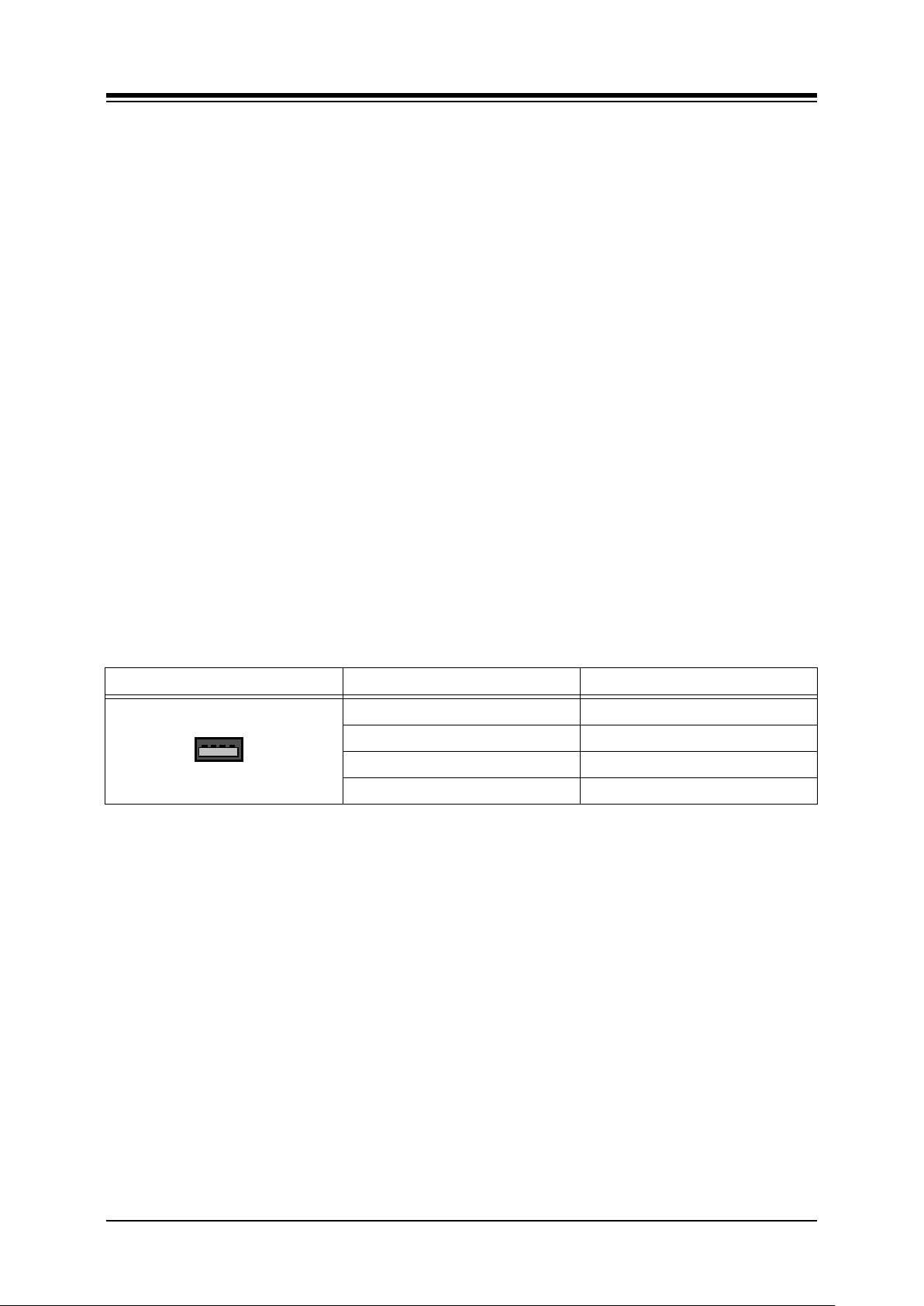
The USB connector is provided to allow a USB memory stick to connect to the system for
upload and download of the System database. No wiring of the USB connector is required. For
further information on operation of the USB port, refer to the iPECS-MG Admin Manual.
Table 5.2.6-1 USB Connector
CONNECTOR PIN SIGNAL NAME
USB Type A
1 GND
2 D+
3 D4 VBUS (+5V)
36
Page 47
iPECS-MG
1
2
3
4
5
6
7
8
9
1
2
3
4
5
6
7
8
9
DTR
TD
CTS
RD
RTS
DSR
SG
DSR
RD
RTS
TD
CTS
DTR
SG
LIK MODULE
DB-9 RS-232
TERMINATIONS
TYPICAL TERMINAL
DB-9 RS-232
TERMINATIONS
Series
9 RS-232
Hardware Description and Installation Manual Issue 1.1
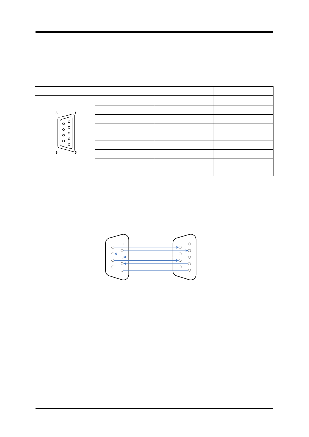
5.2.7 RS-232 Monitor Wiring
The RS-232 female connector, which is a DCE (Data Communication Equipment), is used for
various output functions (SMDR, Traffic Reports, etc.) and can be used to access the System
database and maintenance functions through connection to a local PC.
Table 5.2.7-1 RS-232 Monitor Connector
CONNECTOR PIN SIGNAL FUNCTION
RS-232C
1 Not used
2 TD Transmitted Data
3 RD Received Data
4 DSR Data Set Ready
5 SG Signal Ground
6 DTR Data Terminal Ready
7 CTS Clear to Send
8 RTS Request to Send
9 Not used
NOTE
The RS-232C port on the MPB does not support hardware flow control.
Referring to the pin-out chart above and the wiring diagram below,
wire the RS-232 port to an appropriate DTE (Data Terminal Equipment),
tag or number wiring for maintenance
iPECS-MG DB-
LIP-8000
37
Page 48
iPECS-MG
Hardware Description and Installation Manual Issue 1.1
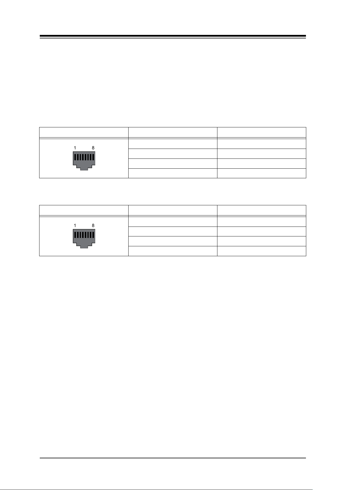
5.2.8 DSIU (Digital and Single Line Int e rf ace Unit) Wiring
The DSIU is included on the MPB and provides six (6) Digital Terminal (DKT-1 to 6) ports and
six (6) Single Line (SLT 1 to 6) ports. The DSIU SLT ports support FSK (ITU-T V.23 or Bell
202) or DTMF (ITU-T Q.23) Caller ID to the SLT. The SLT ports provide the -48 VDC source,
current limited to 20 mA, to operate the SLT, and support Message Wait Indication, DTMF or
Pulse Dial, Polarity reversal, sinusoidal ring generator, and GR-909 Line Testing. The SLT and
DKT ports of the DSIU are terminated in RJ45 connectors located in the front panel of the
board. Note the DSIU is NOT field replaceable.
Table 5.2.8-1 RJ45 Pin Assignment, DKT 1 to 6 Connectors
CONNECTOR PIN SIGNAL NAME
RJ45 1,2,3 Not used
4 DKT-T
5 DKT-R
6,7,8 Not used
Table 5.2.8-2 RJ45 Pin Assignment, SLT 1 to 6 Connectors
CONNECTOR PIN SIGNAL NAME
RJ45 1,2,3 Not used
4 SLT-T
5 SLT-R
6,7,8 Not used
Referring to the pin-out charts above,
Wire the DKT and SLT ports of the DSIU to the termination point of the appropriate
DKT or S LT. For information on terminal wiring, refer to section 6.
Tag or number wiring for maintenance
38
Page 49
iPECS-MG
Hardware Description and Installation Manual Issue 1.1
5.3 CO Line Boards
5.3.1 LCOB (Loop Start CO Line Interface Board)
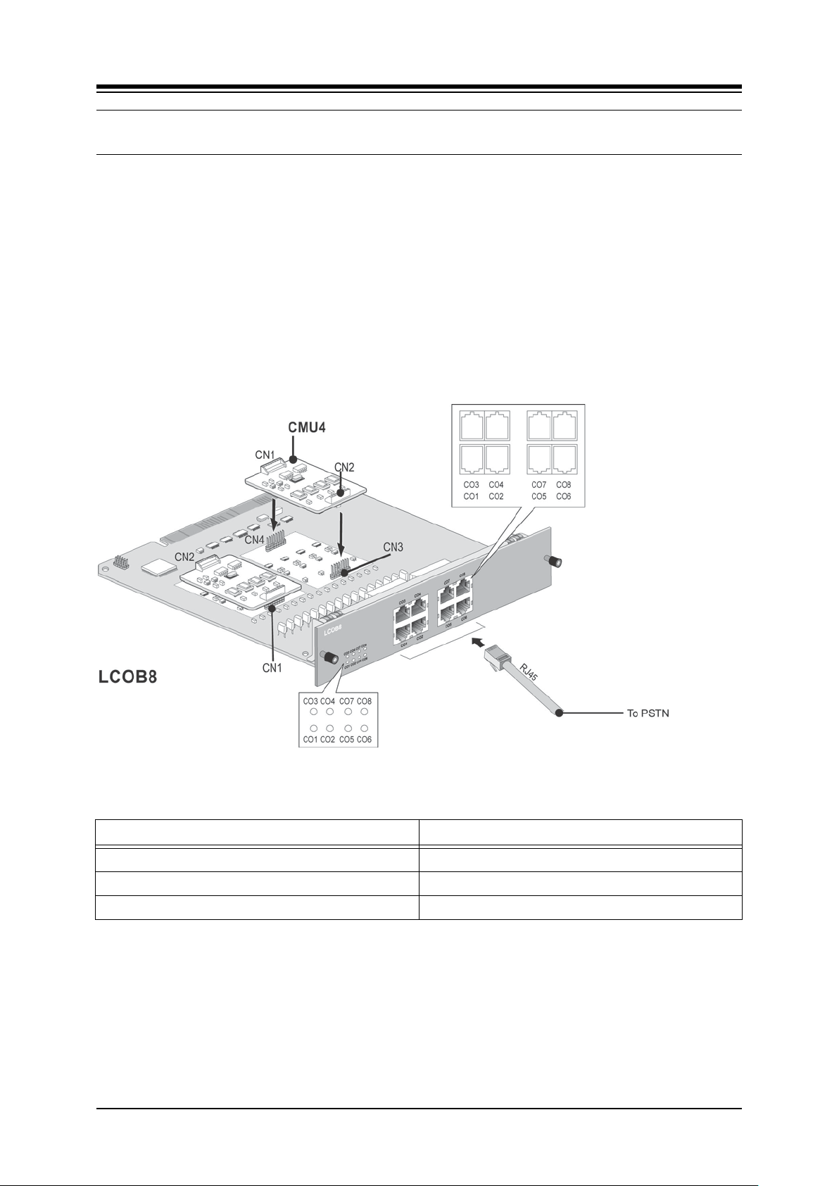
The iPECS-MG LCOB (Loop Start CO Interface Board) is employed to interface standard
analog PSTN CO lines to the iPECS-MG system. The LCOB is available in three models, the
LCOB4 with 4 analog CO ports, the LCOB8 with 8 ports, and the LCOB12 with 12 ports. The
LCOB supports Caller Identification (CID) detection, Polarity Reversal (PR) detection and Call
Progress Tone (CPT) detection. An optional CMU4 board, which supports four (4) LCOB ports
each, is required to support call-metering service (50Hz, 12 kHz, and 16 kHz). In addition, the
first port of the LCOB has a Power Failure Transfer (PFT) circuit that can be wired to an SLIB
port for PFT service.
The below figure shows the LCOB8, which other than the added interface circuits is identical to
the LCOB 4 and 12.
Figure 5.3.1-1 LCOB8
Table 5.3.1-1 Connector Functions
CONNECTOR FUNCTION
CN1 and CN2 CMU4 connection for 1st ~ 4th ports
CN3 and CN4 CMU4 connection for 5th ~ 8th ports
CN5 and CN6 CMU4 connection for 9th ~ 12th ports
39
Page 50

iPECS-MG
Hardware Description and Installation Manual Issue 1.1
Table 5.3.1-2 LED Indications
LED DESCRIPTION LED DESCRIPTION
LD1 1st port - ON, In use ; OFF, Idle LD7 7th port - ON, In use ; OFF, Idle
LD2 2nd port - ON, In use ; OFF, Idle LD8 8th port - ON, In use ; OFF, Idle
LD3 3rd port - ON, In use ; OFF, Idle LD9 9th port - ON, In use ; OFF, Idle
LD4 4th port - ON, In use ; OFF, Idle LD10 10th port - ON, In use ; OFF, Idle
LD5 5th port - ON, In use ; OFF, Idle LD11 11th port - ON, In use ; OFF, Idle
LD6 6th port - ON, In use ; OFF, Idle LD12 12th port - ON, In use ; OFF, Idle
5.3.1.1 CMU (Call Metering Unit) Instal lation
An optional CMU4 board, which supports four (4) LCOB ports each, is required to support callmetering service (50Hz, 12 kHz, and 16 kHz). For additional information on CMU, see the
iPECS-MG Feature Manual.
Install a CMU4 on connector pairs CN1 and 2, CN3 and 4, and CN5 and 6 on the LCOB to
support CO Line ports 1 and 12, as shown in Figure 5.3.1 1. Use care to align pins of the
connector with the CN1 and CN2 connectors on the CMU and press firmly in place.
5.3.1.2 LCOB Installation
Before installation of the LCOB, make sure CMU4s are installed, if required. The LCOB board
can be installed in any universal slot of any KSU; the 1st slot of the BKSU is for the MPB only.
Assure Power is OFF
Slide the LCOB in the guide rails of the desired slot.
Tighten thumbscrews to hold the board firmly in place.
40
Page 51
iPECS-MG
Hardware Description and Installation Manual Issue 1.1
5.3.1.3 LCOB Wiring
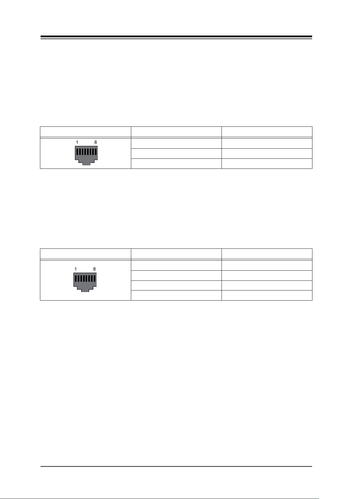
The CO Line Tip and Ring terminations are located on the center pair of each RJ45 connector.
A separate RJ45 is provided for each analog CO Line supported by the LCOB (4, 8, or 12).
Referring to the pin-out chart below,
Wire the CO Tip and Ring pins to the PSTN CO Line termination point using UTP
cable.
Tag or number wiring for maintenance.
Table 5.3.1.3-1 LCOB Ports
CONNECTOR PIN SIGNAL NAME
RJ45 1,2,3 Not used
4,5 CO-T, CO-R
6,7,8 Not used
The first LCOB CO Line port supports PFT (Power Fail Transfer), when power is lost the CO
Line is connected to an SLT port of an SLIB. To support PFT, referring to the pin-out chart
below,
wire pins 1 and 2 of the 1st LCOB port RJ45 to the appropriate SLIB port. For SLIB
wiring, refer to section 5.4.1 and 5.4.2.
tag or number wiring for maintenance
st
Table 5.3.1.3-2 PFT Port 1
CONNECTOR PIN SIGNAL NAME
RJ45 1,2 PFT-T, PFT-R
3 Not used
4,5 CO-T, CO-R
6,7,8 Not used
Port
41
Page 52
iPECS-MG
Hardware Description and Installation Manual Issue 1.1
5.3.2 BRIB (Basic Rate Interface Board) w/Selectable S/T Interface
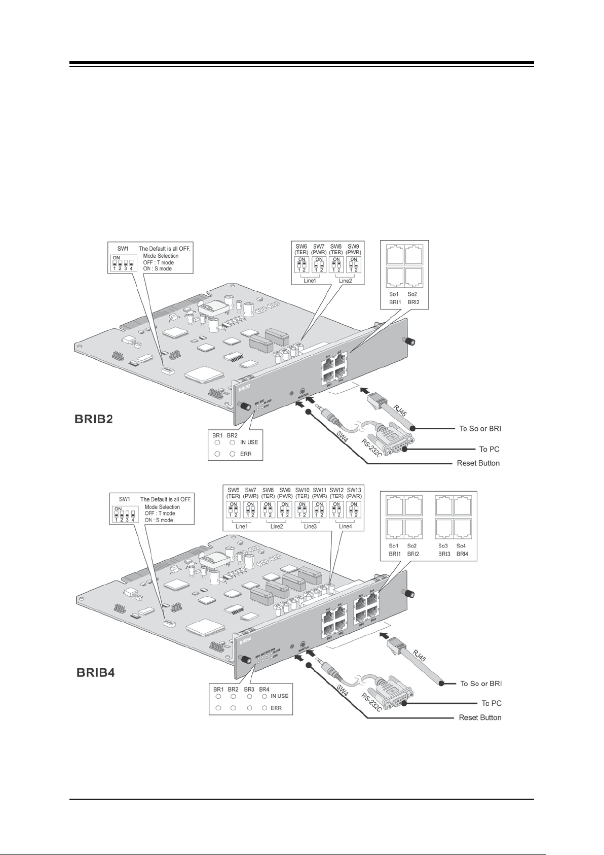
There are two kinds of BRIB2/BRIB4 according to CPU, but they have the same functions.
The BRIB is available in two models, the BRIB2 with two (2) BRI lines (4 channels) and the
BRIB4 with four (4) BRI lines (8 channels). The BRIB is compatible with ETSI 300.012 and ITUT recommendations I.430 supporting S (Subscriber) or T (Trunk) interfaces. As shown in Figure
5.3.2.1, the S interface of the BRIB acts as the NT (Network Termination) connecting to TEs
(Terminal Equipments) and can provide power feed (-40VDC) to the attached TEs (maximum
eight TEs). A 100-ohm Terminating Resistor can be inserted across the TX and/or RX pair.
When used, a 100-Ohm terminating resistor should be connected across the TX and RX pair at
one of the TEs.
42
Page 53
iPECS-MG
Hardware Description and Installation Manual Issue 1.1
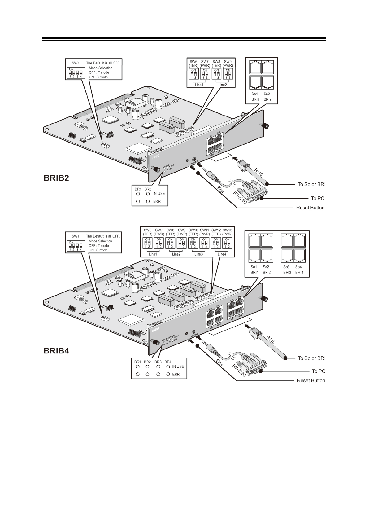
Figure 5.3.2-1 BRIB2 and BRIB4
Note
iPECS-MG does not support daisy chained clocking for digital lines. The clock priority
and synchronization is controlled by Admin. For details, refer to PGM 301 of the iPECSMG Admin Manual.
43
Page 54

iPECS-MG
Hardware Description and Installation Manual Issue 1.1
The default clock is assigned based on the board type, KSU, and slot as below.
− Board – PRIB > BRIB2/BRIB4 > Internal Clock
− KSU – 1’st KSU > 2’nd KSU > 3’rd KSU
− Slot – Slot 1 > Slot 2 >…> Slot 18
5.3.2.1 Switch and LED Functions
Table 5.3.2.1-1 BRIB Line Mode Switch SW1
SWICTH FUNCTION ON OFF
SW1-1 Line #1 mode S-mode T-mode
SW1-2 Line #2 mode S-mode T-mode
SW1-3 Line #3 mode S-mode T-mode
SW1-4 Line #4 mode S-mode T-mode
Note
The default setting is T Mode for all switches. SW1-3 and SW1-4 are for BRIB4 only.
Table 5.3.2.1-2 BRIB Terminating Resister (100-Ohm)
SWITCH FUNCTION ON OFF
SW6-1 Line 1 TX resistor Terminate Open
SW6-2 Line 1 RX resistor Terminate Open
SW8-1 Line 2 TX resistor Terminate Open
SW8-2 Line 2 RX resistor Terminate Open
SW10-1 Line 3 TX resistor Terminate Open
SW10- 2 Line 3 RX resistor Terminate Open
SW12-1 Line 4 TX resistor Terminate Open
SW12-2 Line 5 RX resistor Terminate Open
44
Page 55

iPECS-MG
Hardware Description and Installation Manual Issue 1.1
Table 5.3.2.1-3 BRIB Power Feed
SWITCH FUNCTION ON OFF
SW7-1 Line 1 Pow er Feed (-40V) Feed Open
SW7-2
SW9-1 Line 2 Pow er Feed (-40V) Feed Open
SW9-2
SW11-1 Line 3 Power Feed (-40V) Feed Open
SW11- 2
SW13-1 Line 4 Power Feed (-40V) Feed Open
SW13-2
Line 1 Power Feed
(Ground)
Line 2 Power Feed
(Ground)
Line 3 Power Feed
(Ground)
Line 4 Power Feed
(Ground)
Feed Open
Feed Open
Feed Open
Feed Open
Table 5.3.2.1-4 LED Indication, BRIB2
NO FUNCTION STATUS
LD1
LD3
LD2
LD4
Line 1 status Red: ON = Error
Blue: ON = In-use, OFF = Idle
Line 2 status Red: ON = Error
Blue: ON = In-use, OFF: = Idle
Table 5.3.2.1-5 LED Indication, BRIB4
NO FUNCTION STATUS
LD1
LD5
LD2
LD6
LD3
LD7
LD4
LD8
Line 1 status Red: ON = Error
Blue: ON = In-use, OFF = Idle
Line 2 status Red: ON = Error
Blue: ON = In-use, OFF = Idle
Line 3 status Red: ON = Error
Blue: ON = In-use, OFF = Idle
Line 4 status Red: Error
Blue: ON = In-use, OFF = Idle
45
Page 56

iPECS-MG
Hardware Description and Installation Manual Issue 1.1
5.3.2.2 BRIB Installation
Before installation of the BRIB, set the Mode, Terminating Resistor, and Power Feed Switches
for each BRIB Line. Note that the BRIB cannot simultaneously support both the T and S mode,
all ports on the BRIB must be set in the same mode, T or S.
The BRIB board can be installed in any universal slot of any KSU; the 1st slot of the BKSU is
for the MPB only.
Assure Power is OFF
Slide the BRIB in the guide rails of the desired slot.
Tighten thumbscrews to hold the board firmly in place.
5.3.2.3 BRIB Wiring
A separate RJ45 connector is provided for each BRI line supported by the BRIB. Referring to
the pin-out chart and Figure 5.3.2.3 1 below,
Wire the TX and RX pins of each RJ-45 connector to the BRI digital line termination
point using UTP cable.
Tag or number wiring for maintenance.
46
Page 57
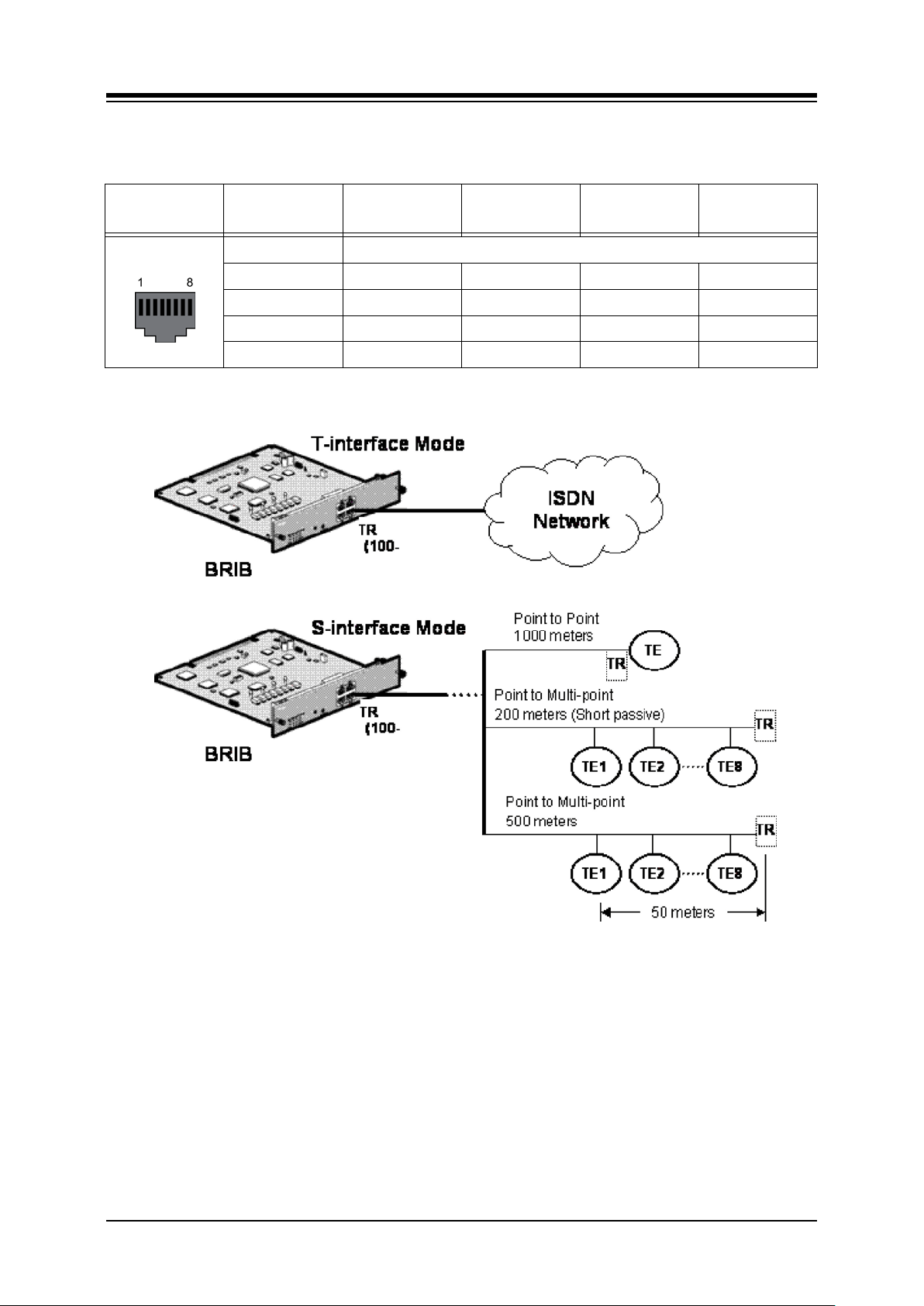
iPECS-MG
Hardware Description and Installation Manual Issue 1.1
Table 5.3.2.3-1 RJ45
CONECTOR PIN
RJ45 1,2,7,8 Reserved
3 TX+ Transmit Data RX+ Receive Data
4 RX+ Receive Data TX+ Transmit Data
5 RX- Receive Data TX- Transmit Data
6 TX- Transmit Data RX- Receive Data
NAME
(T-mode)
FUNCTION
NAME
(S-mode)
FUNCTION
Figure 5.3.2.3-1 ISDN Connections (Basic Rate)
5.3.2.4 Serial Port
The PRIB includes an Audio jack connected to a Serial port. The serial port is used for
diagnostic purposes. For wiring information, refer to section 5.6.
47
Page 58
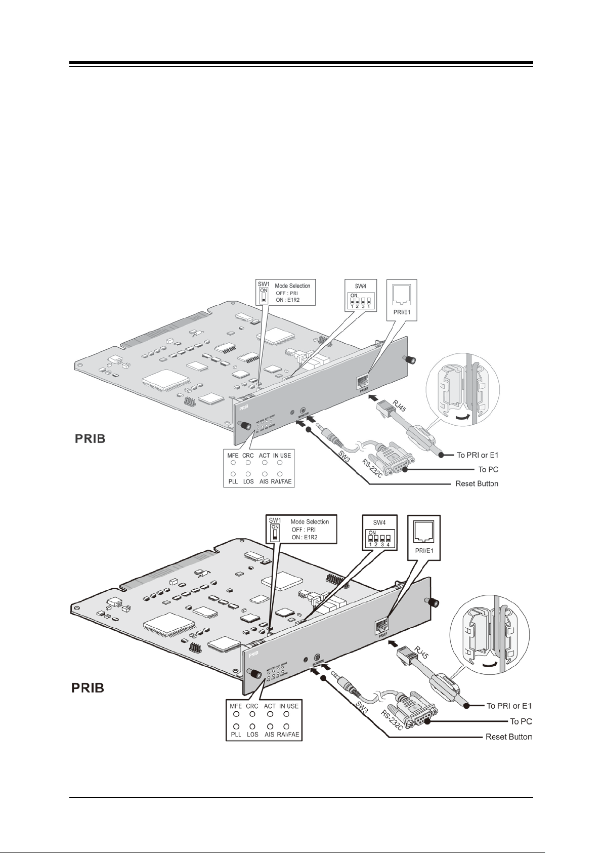
iPECS-MG
Hardware Description and Installation Manual Issue 1.1
5.3.3 E1R2-PRIB (Primary Rate Inte rface Board)
There are two kinds of PRIB according to CPU, but they have the same functions.
The Primary Rate Interface Board (PRIB) provides one (1) PRI interface, or one (1) E1R2
interface. The PRI interface supports 30 PCM bearer and 2 signaling channels for PRI or E1R2.
The PRIB is based on the interface described in ITU-T Recommendations G.704, G.703, and
G.823. It covers CEPT frame format that consist of 32 8-bit timeslots, a data rate of 2.048MHz.
From the 32 timeslots in a frame, 30 timeslots are defined as information channels, timeslots 115 and 17-31 that correspond to telephone channels 1-30. The frame has duration of 125ųsec
and contains 32 Time Slots (TS). Time Slot 0 is allocated to frame alignment sync, and Time
Slot 16 is allocated to the signaling channel; the other time slots are available for allocation to
the B channel. The CEPT frame has four signaling bits, A, B, C and D. Signaling bits for all 30
media channels are transmitted in timeslot 16. The PRIB supports pulse dialing, DTMF dialing,
and MFC-R2 register signaling (based on ITU-T Recommendation Q.440-480).
Figure 5.3.3-1 E1-PRIB
48
Page 59

iPECS-MG
Hardware Description and Installation Manual Issue 1.1
CAUTION
For QSIG operation, check the mode setting and the pin assignments of RJ45 type
connector according to the mode of line, TE or NT.
NOTE
iPECS-MG does not support daisy chained clocking for digital lines. The clock priority
and synchronization is controlled by Admin. For details, refer to PGM 301 of the iPECSMG Admin Manual.
The default clock is assigned based on the board type, KSU, and slot as below.
− Board – PRIB > BRIB2/BRIB4 > Internal Clock
− KSU – 1’st KSU > 2’nd KSU > 3’rd KSU
− Slot – Slot 1 > Slot 2 >…> Slot 18
5.3.3.1 Switch and LED Functions
Table 5.3.3.1-1 Switch-Functions
SWITCH FUNCTION REMARK
SW1 Mode Selection (OFF = PRI, ON = E1R2) Default: PRI mode
SW3 Reset switch
SW4-1 N ot used
SW4-2 N ot used
SW4-3 N ot used
SW4-4 N ot used
Table 5.3.3.2-2 LED-Indication
LED PRI MODE E1 R2 MODE REMARK
LD1 PLL Synchronizat ion
LD2 Loss of Signal from the Line
LD3 Alarm Indication Signal
LD4 Remote Alarm Indication Frame Alignment Error
LD5 Multi Frame Error
LD6 CRC Error
LD7 Normal operation indication (Activit y Indication) Blue (Blink)
LD8 Channel status
CRC
(ON : Enable, OFF : Disable)
RED LED
ON: Error
OFF: Normal operation
Blue LED
ON: Channels in use
OFF: All channels Idle)
5.3.3.2 E1-PRIB Installation
Before inserting the PRIB, set SW1 and SW4 Dip switches to match the Telco provided service.
The PRIB board can be installed in any universal slot of any KSU; the 1st slot of the BKSU is
for the MPB only.
49
Page 60
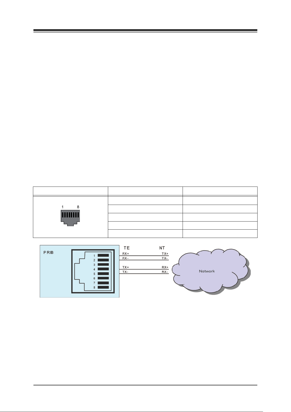
iPECS-MG
Hardware Description and Installation Manual Issue 1.1
Assure Power is OFF
Slide the PRIB in the guide rails of the desired slot.
Tighten thumbscrews to hold the board firmly in place.
5.3.3.3 E1-PRIB Wiring
The E1-PRIB Transmit and Receive pairs are terminated in the PRI/E1 RJ45 connector. A
single RJ45 is provided for the digital line interface.
Before wiring the PRIB, the Ferrite core provided with the E1-PRIB must be installed to reduce
EMI (Electro-Magnetic Interference). To install the Ferrite core,
Open the core,
Insert and loop the RJ45 terminated cable for the E1-PRIB through the core as
shown in Figure 5.3.3-1.
Close the Ferrite core over the cable.
Referring to the pin-out chart and Figure 5.3.3.3-1 E1-PRIB Connector Wiring Diagram below,
Wire the TX and RX pins of the RJ45 connector to the digital line termination point
using UTP cable.
Tag or number wiring for maintenance.
Table 5.3.3.3-1 PRI Port
CONNECTOR PIN SIGNAL
RJ45 1 RX+
2 RX4 TX+
5 TX-
3,6,7,8 Not used
Figure 5.3.3.3-1 E1-PRIB Connector Wiring Diagram
5.3.3.4 Serial Port
The PRIB includes an Audio jack connected to a Serial port. The serial port is used for
diagnostic purposes. For wiring information, refer to section 5.6.
50
Page 61
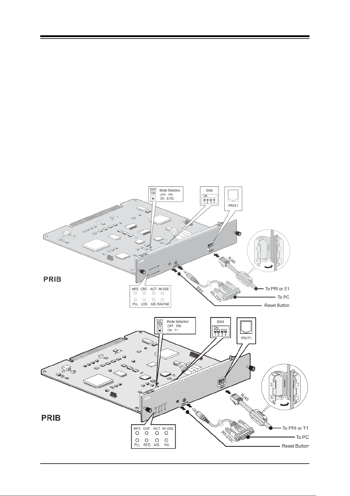
iPECS-MG
Hardware Description and Installation Manual Issue 1.1
5.3.4 T1-PRIB (Primary Rate Interf a c e Board)
There are two kinds of PRIB according to CPU, but they have the same functions.
The T1 and Primary Rate Interface (PRI) board interfaces to North American standards based
digital networks. Standard alarms are provided by on-board LEDs (refer to chart below). The
PRIB includes the T1-PRI interface, control and synchronous clock circuitry as well as standard
alarm indications using front panel LEDs (refer to LED Indications chart below.
The board is switch-selectable (SW1) for T1 or PRI operation both operating with a 125 usec
frame at 1.544Mb/s. In T1 operation, the standards EIA/TIA-464-A and TR 41458 24-channel
interface supporting DID, TIE Line, and Loop or Ground Start are implemented. The DID and
TIE Line operation support Immediate, Delayed and Wink start signaling protocols. The Telco
interface must provide BZ8S line coding and Extended Super Frame (ESF) framing.
In PRI operation, the ISDN standard NII2 (National ISDN Interface 2) 23 Bearer and one (1)
Data channel interface is supported. The PRI operation employs ANSI T1.403, T1.601, T1.605,
and TR62411 standards.
Connection is made via a RJ45 from the PRIB to a CSU (Channel Service Unit).
Figure 5.3.4-1 T1 PRIB
51
Page 62

iPECS-MG
OFF = Normal)
Hardware Description and Installation Manual Issue 1.1
NOTE
iPECS-MG does not support daisy chained clocking for digital lines. The clock priority
and synchronization is controlled by Admin. For details, refer to PGM 301 of the iPECSMG Admin Manual.
The default clock is assigned based on the board type, KSU, and slot as below.
− Board – PRIB > BRIB2/BRIB4 > Internal Clock
− KSU – 1’st KSU > 2’nd KSU > 3’rd KSU
− Slot – Slot 1 > Slot 2 >…> Slot 18
5.3.4.1 Switch and LED Functions
Table 5.3.4.1-1 Switch Functions
SWITCH FUNCTION REMARK
SW1 Mode Selection (OFF = PRI, ON = T1) Default: PRI mode
SW3 Reset sw it ch
SW4-1 Not used
SW4-2 Not used
SW4-3 Not used
SW4-4 Not used
LED FUNCTION REMARK
PLL PLL Synchronization
RDE Red Alarm Indication)
AIS Alarm Indication Signal/Blue Alar m
YAI Yellow Alarm Indication
MFE Multi-frame Establish Alarm
OOF Out of Frame
ACT Activity Indication Blue (Blink)
IN USE Indication of channel use
5.3.4.2 T1-PRIB Installation
Table 5.3.4.1-2 LED Indication
Red LED
ON = Error
Blue LED
ON: Channels in use,
OFF: All channels idle
Before inserting the T1-PRIB, set SW1 and SW4 Dip switches to match the Telco provided
service. Note that the PRIB supports ESF (Extended Super Frame) framing and B8ZS (Binary
8 Zero Substitution) line coding only. The T1-PRIB board can be installed in any universal slot
of any KSU; the 1st slot of the BKSU is for the MPB only.
Assure Power is OFF.
Slide the PRIB in the guide rails of the desired slot.
Tighten thumbscrews to hold the board firmly in place.
52
Page 63

iPECS-MG
Hardware Description and Installation Manual Issue 1.1
5.3.4.3 T1-PRIB Wiring
The T1-PRIB Transmit and Receive pairs are terminated in the PRI/T1 RJ45 connector. A
single RJ45 is provided for the digital line interface.
Before wiring the PRIB, the Ferrite core provided with the T1-PRIB must be installed to reduce
EMI (Elector-Magnetic Interference). To install the Ferrite core,
Open the core.
Insert and loop the RJ45 terminated cable for the T1-PRIB through the core as
shown in Figure 5.3.4-1.
Close the Ferrite core over the cable.
Referring to the pin-out chart and Figure 5.3.3.3-1 E1-PRIB Connector Wiring Diagram below,
Wire the TX and RX pins of the RJ45 connector to the digital line termination point
at the CSU using UTP cable.
Tag or number wiring for maintenance.
Table 5.3.4.3-1 T1 PRI Port
CONNECTOR PIN SIGNAL
RJ45 1 RX+
2 RX4 TX+
5 TX-
3,6,7,8 Not used
Figure 5.3.4.3-1 T1-PRIB Connector Wiring Diagram
5.3.4.4 Serial Port
The PRIB includes an Audio jack connected to a Serial port. The serial port is used for
diagnostic purposes. For wiring information, refer to section 5.6.
53
Page 64
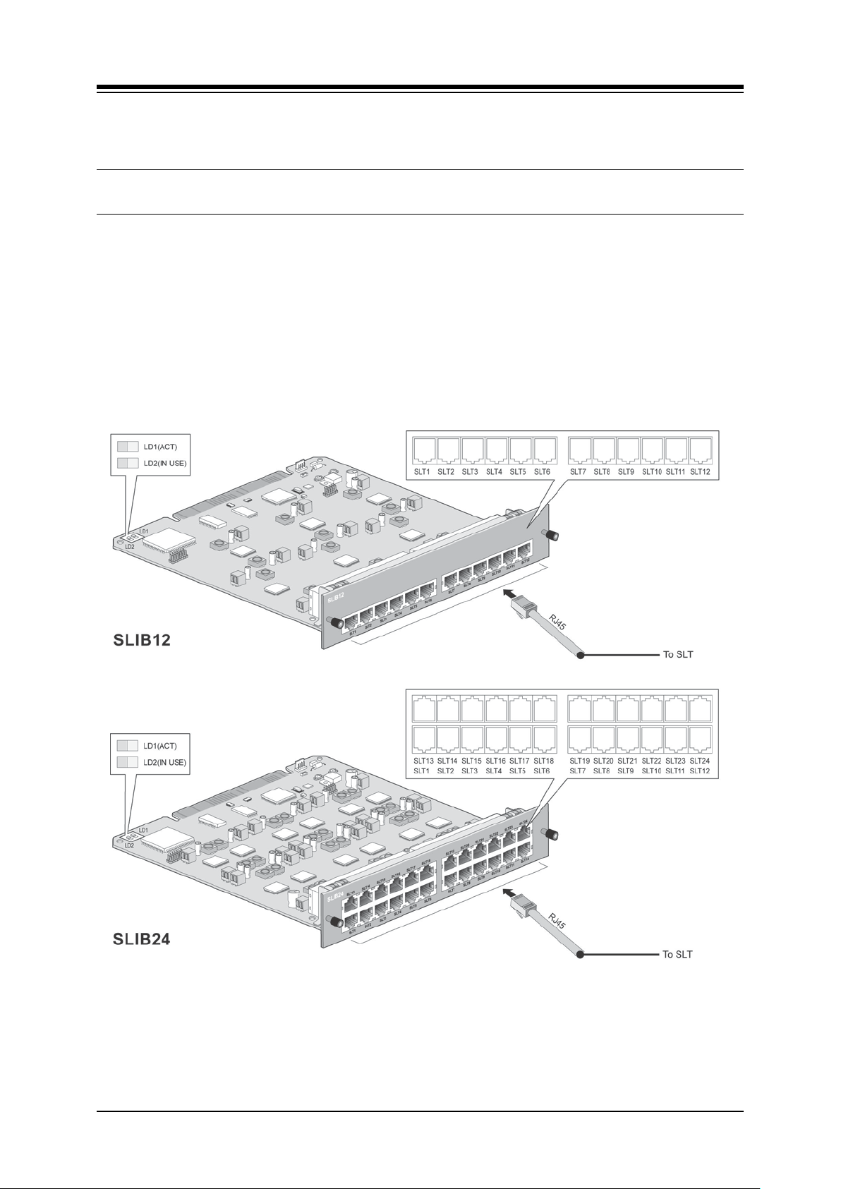
iPECS-MG
Hardware Description and Installation Manual Issue 1.1
5.4 Extension Boards
5.4.1 SLIB (Single Line Interface Board w/RJ45)
There are two kinds of SLIB12/SLIB24 according to CPU, but they have the same functions.
The SLIB is available in two (2) models, the SLIB 12 with 12 analog Single Line Telephone
ports and the SLIB24 with 24 SLT ports. In both cases, the SLT ports are each terminated in an
RJ45 connector. The SLIB provides FSK (ITU-T V.23 or Bell 202) or DTMF (ITU-T Q.23) Caller
ID function to the SLT. The SLT ports provide the -48 VDC source, current limited to 20 mA, to
operate the SLT and support the Message Wait Indication, DTMF, or Pulse Dial signaling,
Polarity reversal, sinusoidal Ring generator, and GR-909 Line Testing.
54
Page 65
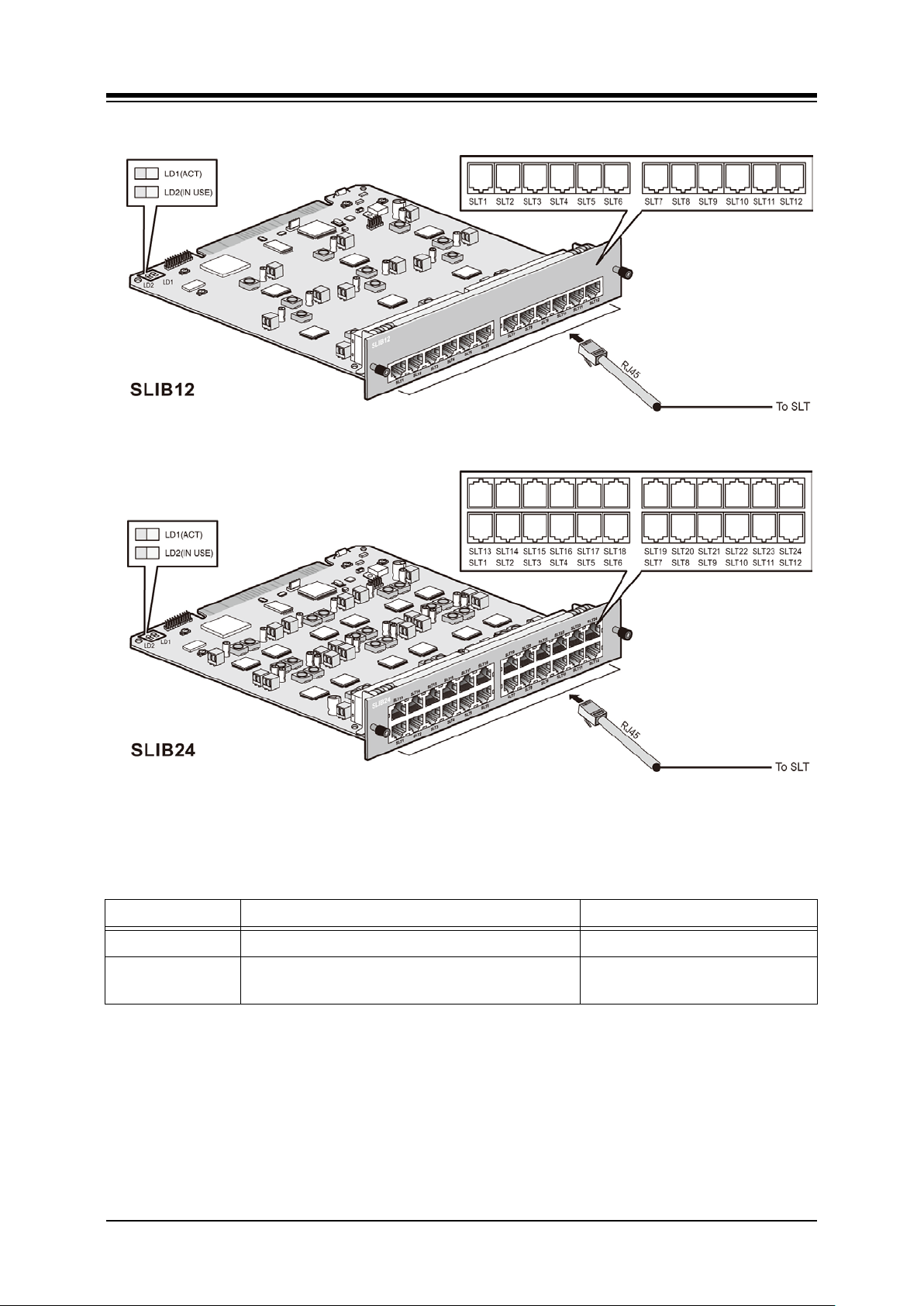
iPECS-MG
Hardware Description and Installation Manual Issue 1.1
5.4.1.1 LED Functions
LED FUNCTION REMARK
LD1 ACT, Activation or Normal O perating Blink (Blue Color)
LD2 IN USE
Figure 5.4.1-1 SLIB12/24
ON: one or ports in use
OFF: All channels, Idle
5.4.1.2 SLIB Installation
The SLIB has no switches or connectors that are field useable. The SLIB can be installed in
any universal slot of any KSU; the 1st slot of the BKSU is for the MPB only. Note a maximum of
four (4) DTIB24/SLIB24s can be installed in a KSU.
Assure Power is OFF.
Slide the SLIB in the guide rails of the desired slot.
Tighten thumbscrews to hold the board firmly in place.
55
Page 66
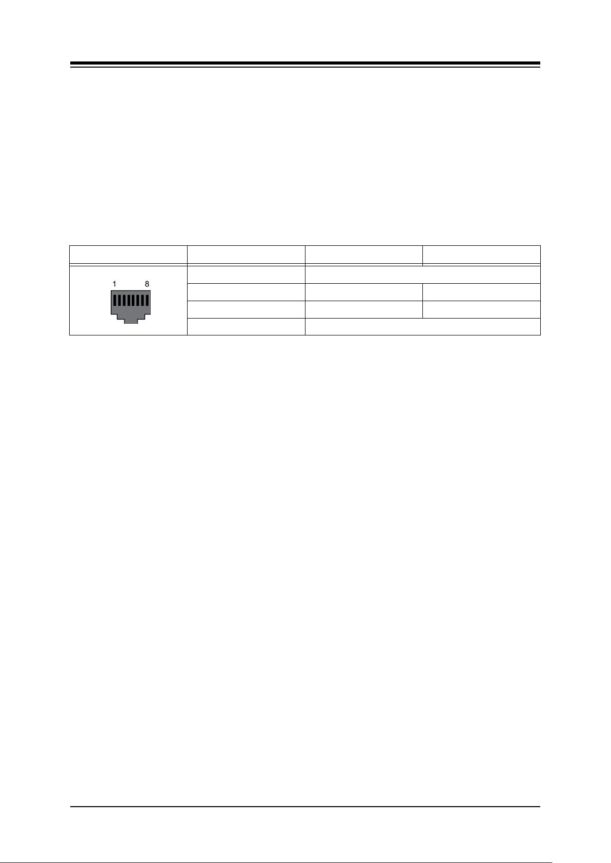
iPECS-MG
Hardware Description and Installation Manual Issue 1.1
5.4.1.3 SLIB Wiring
The SLT is terminated to the center pair of each RJ45 connector. A separate RJ45 is provided
for each SLT port on the SLIB (12 or 24 connectors).
Referring to the pin-out chart below,
Wire pins 4 and 5 of the RJ45 connector to the SLT termination point using UTP
cable. The maximum total wire length is 7500M/24Kft of 22 AWG wire or
5000M/16Kft of 24 AWG wire. For information on wiring the SLT, refer to section
6.1.2.2.
Tag or number wiring for maintenance.
Table 5.4.1.3.1 SLIB 12/24
CONNECTOR PIN SIGNAL NAME FUNCTION
RJ45 1,2,3 Not used
4 SLT_RX Receive Data
5 SLT_TX T r ansmit Data
6,7,8 Not used
56
Page 67
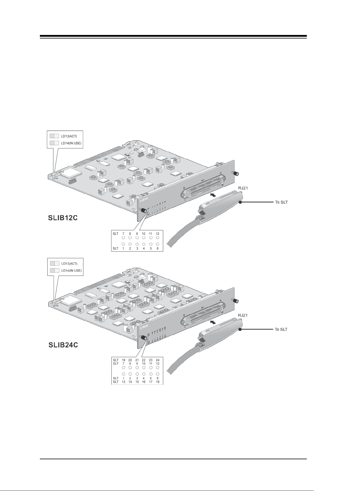
iPECS-MG
Hardware Description and Installation Manual Issue 1.1
5.4.2 SLIBC (Single Line Inter f a ce Board w/RJ21)
There are two kinds of SLIB12C/SLIB24C according to CPU, but they have the same functions.
The SLIBC is available in two (2) models, the SLIB12C with 12 SLT ports and the SLIB24C
with 24 SLT ports. The SLIBC is identical to the SLIB except the SLT ports of the SLIBC are
terminated in a 25-pair RJ21 female connector. The SLIBC provides FSK (ITU-T V.23 or Bell
202) or DTMF (ITU-T Q.23) Caller ID function to the SLT. The SLT ports provide the -48 VDC
source, current limited to 20 mA, to operate the SLT and support the Message Wait Indication,
DTMF, or Pulse Dial signaling, Polarity reversal, sinusoidal Ring generator, and GR-909 Line
Testing.
57
Page 68
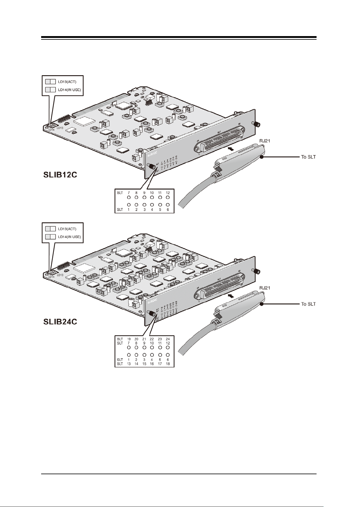
iPECS-MG
Hardware Description and Installation Manual Issue 1.1
Figure 5.4.2-1 SLIB12/24C
58
Page 69

iPECS-MG
Hardware Description and Installation Manual Issue 1.1
5.4.2.1 LED Functions
Table 5.4.2.1-1 LED Indications
LED FUNCTION REMARK
LD1
The status of 1st port or 13
LD2 The status of 2nd port or 14
LD3 The status of 3rd port or 15
LD4 The status of 4th port or 16
LD5 The status of 5th port or 17
LD6 The status of 6th port or 18
LD7 The status of 7th port or 19
LD8 The status of 8th port or 20
th
th
th
th
th
th
th
th
port
port
port
port
port
port
port
port
LD9 The status of 9th port or 21st port
LD10 The status of 10th port or 22nd port
ON (Blue) : 1st port in use
ON (Yellow Green) : 13
th
port in use
ON (Blush white) : 1st and 13th port in use
OFF: Idle
ON (Blue) : 2nd port in use
ON (Yellow Green) : 14
th
port in use
ON (Blush white) : 2nd and 14th port in use
OFF: Idle
ON (Blue) : 3rd port in use
ON (Yellow Green) : 15th port in use
ON (Blush white) : 3rd and 15th port in use
OFF: Idle
ON (Blue) : 4th port in use
ON (Yellow Green) : 16
th
port in use
ON (Blush white) : 4th and 16th port in use
OFF: Idle
ON (Blue) : 5th port in use
ON (Yellow Green) : 17
th
port in use
ON (Blush white) : 5th and 17th port in use
OFF: Idle
ON (Blue) : 6th port in use
ON (Yellow Green) : 18th port in use
ON (Blush white) : 6th and 18th port in use
OFF: Idle
ON (Blue) : 7th port in use
ON (Yellow Green) : 19
th
port in use
ON (Blush white) : 7th and 19th port in use
OFF: Idle
ON (Blue) : 8th port in use
ON (Yellow Green) : 20
th
port in use
ON (Blush white) : 8th and 20th port in use
OFF: Idle
ON (Blue) : 9th port in use
ON (Yellow Green) : 21st port in use
ON (Blush white) : 9th and 21st port in use
OFF: Idle
ON (Blue) : 10th port in use
ON (Yellow Green) : 22
nd
port in use
ON (Blush white) : 10th and 22nd port in use
OFF: Idle
59
Page 70

iPECS-MG
Hardware Description and Installation Manual Issue 1.1
Table 5.4.2.1-1 LED Indications
LED FUNCTION REMARK
LD11
LD12
LD13
LD14
ON (Blue) : 11th port Use
The status of 11th port or 23rd port
The status of 12th port or 24
ACT, Activation or Normal Operating Blink (Blue Color)
In use
th
port
ON (Yellow Green) : 23
ON (Blush white) : 11th and 23rd port in use
OFF: Idle
ON (Blue) : 12
ON (Yellow Green) : 24
ON (Blush white) : 12th and 24th port in use
OFF: Idle
ON: Ch. Use,
OFF: All channels Idle
th
rd
port in use
port in use
th
port in use
5.4.2.2 SLIBC Installation
The SLIB has no switches or connectors that are field useable. The SLIB can be installed in
any universal slot of any KSU; the 1st slot of the BKSU is for the MPB only. Note a maximum of
four (4) DTIB24/SLIB24Cs can be installed in a KSU.
Assure Power is OFF
Slide the SLIBC in the guide rails of the desired slot.
Tighten thumbscrews to hold the board firmly in place.
5.4.2.3 SLIBC Wiring
Each SLT port is terminated to a pair in the RJ21 connector. SLT 1 is terminated at pair 1, SLT
2 is terminated on pair 2, etc. to the number of ports (12 or 24) on the SLIBC.
Referring to the pin-out chart below,
Wire each SLT pair on the RJ21 connector to the SLT termination point using UTP
cable. The maximum total wire length is 7500M/24Kft of 22 AWG wire or
5000M/16Kft of 24 AWG wire. For information on wiring the SLT, refer to section
6.1.2.2
Tag or number wiring for maintenance.
60
Page 71

iPECS-MG
Hardware Description and Installation Manual Issue 1.1
Table 5.4.2.1-2 SLIBC Pin-Out Chart
CONNECTOR PIN COLOR CODE SLIB PORT
VT VR
RJ21 1 26 1
2 27 2
3 28 3
4 29 4
5 30 5
6 31 6
7 32 7
8 33 8
9 34 9
10 35 10
11 36 11
12 37 12
13 38 13
14 39 14
15 40 15
16 41 16
17 42 17
18 43 18
19 44 19
20 45 20
21 46 21
22 47 22
23 48 23
24 49 24
25 50
61
Page 72
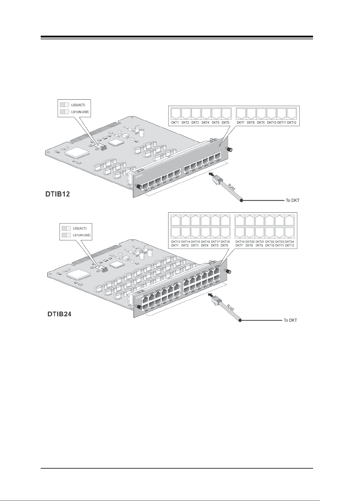
iPECS-MG
Hardware Description and Installation Manual Issue 1.1
5.4.3 DTIB (Digital Terminal I nt er f a c e Board w/RJ-45)
The DTIB is available in two (2) models, the DTIB12 with 12 Digital Key Telephone Interface
ports and the DTIB24 with 24 DKT ports. Each port provides power and signaling to the DKT
over a single wire pair. Each DKT port of the DTIB is terminated in an RJ45 connector on the
front panel of the DTIB.
Figure 5.4.3-1 DTIB (Digital Telephone Interface Board
62
Page 73
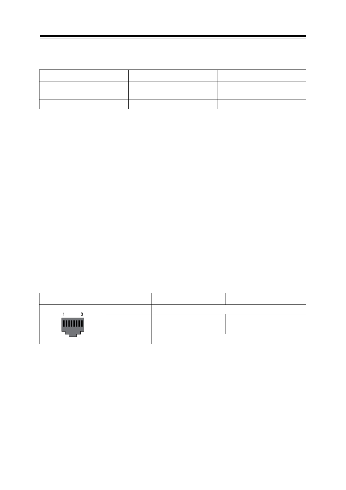
iPECS-MG
Hardware Description and Installation Manual Issue 1.1
5.4.3.1 LED Functions
Table 5.4.5.1-1 LED Indication
LED FUNCTIONS REMARK
LD1 IN USE
LD2 ACT, Activation or Normal Operating Blink (Blue Color)
ON: Channel in use,
OFF: All channels Idle
5.4.3.2 DTIB Installation
The DTIB has no switches or connectors that are field useable. The DTIB can be installed in
any universal slot of any KSU; the 1st slot of the BKSU is for the MPB only. Note a maximum of
four (4) DTIB24/SLIB24s can be installed in a KSU.
Assure Power is OFF
Slide the DTIB in the guide rails of the desired slot.
Tighten thumbscrews to hold the board firmly in place.
5.4.3.3 DTIB Wiring
A separate RJ45 is provided for each DKT port on the DTIB (12 or 24 connectors). DKT ports
terminate on the center pair of the RJ45 connectors.
Referring to the pin-out chart below,
Wire pins 4 and 5 of the RJ45 connector to the DKT termination point using UTP
cable. The maximum total wire length is 500M/1.6Kft of 22 AWG or 330M/1Kft of 24
AWG wire. For information on wiring the Digital Key Telephone, refer to section
6.1.2.1
Tag or number wiring for maintenance.
Table 5.4.5.3-1 DTIB RJ45 Pin-Out Chart
CONNECTOR PIN SIGNAL NAME FUNCTION
RJ45 1,2,3 Not used
4 DKT_RX Receive Data
5 DKT_TX Transmit Data
6,7,8 Not used
63
Page 74

iPECS-MG
Hardware Description and Installation Manual Issue 1.1
5.4.4 DTIBC (Digital Telephone Inte rface Board w/RJ21 connector)
The DTIBC is available in two (2) models, the DTIB12 with 12 Digital Key Telephone Interface
ports and the DTIB24 with 24 DKT ports. The DTIBC is identical to the DTIB except the DKT
ports of the DTIBC are terminated to an RJ21 connector. Each port provides power and
signaling to the DKT over a single wire pair.
Figure 5.4.4-1 DTIB Digital Telephone Interface Board
64
Page 75

iPECS-MG
Hardware Description and Installation Manual Issue 1.1
5.4.4.1 LED Functions
Table 5.4.6.1-1 LED Indication
LED FUNCTION REMARK
LD1 The status of 1st port or 13th port
LD2 The status of 2nd port or 14
LD3 The status of 3rd port or 15
th
th
port
port
LD4 The status of 4th port or 16th port
LD5 The status of 5th port or 17
LD6 The status of 6th port or 18
LD7 The status of 7th port or 19
LD8 The status of 8th port or 20
LD9 The status of 9th port or 21
th
th
th
th
st
port
port
port
port
port
LD10 The status of 10th port or 22nd port
ON (Blue) : 1st port Use
ON (Yellow Green) : 13
th
port Use
ON (Blush white) : 1st and 13th port Use
OFF: Idle
ON (Blue) : 2nd port Use
ON (Yellow Green) : 14
th
port Use
ON (Blush white) : 2nd and 14th port Use
OFF: Idle
ON (Blue) : 3rd port Use
ON (Yellow Green) : 15th port Use
ON (Blush white) : 3rd and 15th port Use
OFF: Idle
ON (Blue) : 4th port Use
ON (Yellow Green) : 16
th
port Use
ON (Blush white) : 4th and 16th port Use
OFF: Idle
ON (Blue) : 5th port Use
ON (Yellow Green) : 17
th
port Use
ON (Blush white) : 5th and 17th port Use
OFF: Idle
ON (Blue) : 6th port Use
ON (Yellow Green) : 18th port Use
ON (Blush white) : 6th and 18th port Use
OFF: Idle
ON (Blue) : 7th port Use
ON (Yellow Green) : 19
th
port Use
ON (Blush white) : 7th and 19th port Use
OFF: Idle
ON (Blue) : 8th port Use
ON (Yellow Green) : 20
th
port Use
ON (Blush white) : 8th and 20th port Use
OFF: Idle
ON (Blue) : 9th port Use
ON (Yellow Green) : 21st port Use
ON (Blush white) : 9th and 21st port Use
OFF: Idle
ON (Blue) : 10th port Use
ON (Yellow Green) : 22
nd
port Use
ON (Blush white) : 10th and 22nd port Use
OFF: Idle
65
Page 76

iPECS-MG
Hardware Description and Installation Manual Issue 1.1
Table 5.4.6.1-1 LED Indication
LED FUNCTION REMARK
ON (Blue) : 11th port Use
LD11 The status of 11th port or 23rd port
LD12 The status of 12th port or 24th port
LD13 ACT, Activation or Normal Operating Blink (Blue Color)
LD14 In use
ON (Yellow Green) : 23rd port Use
ON (Blush white) : 11th and 23rd port Use
OFF: Idle
ON (Blue) : 12th port Use
ON (Yellow Green) : 24
ON (Blush white) : 12th and 24th port Use
OFF: Idle
ON: Ch. Use,
OFF: All channels Idle
th
port Use
5.4.4.2 DTIBC Installation
The DTIBC has no switches or connectors that are field useable. The DTIBC can be installed in
any universal slot of any KSU; the 1st slot of the BKSU is for the MPB only. Note a maximum of
four (4) DTIB24C/SLIB24s can be installed in a KSU.
Assure Power is OFF
Slide the DTIBC in the guide rails of the desired slot.
Tighten thumbscrews to hold the board firmly in place.
5.4.4.3 DTIBC Wiring
Each DKT port is terminated to a pair in the RJ21 connector. DKT 1 is terminated at pair 1,
DKT 2 is terminated on pair 2, etc. to the number of ports (12 or 24) on the DTIBC.
Referring to the pin-out chart below,
Wire each DKT pair on the RJ21 connector to the DKT termination point using UTP
cable. The maximum total wire length is 500M/1.6Kft of 22 AWG or 330M/1Kft of 24
AWG wire. For information on wiring the DKT, refer to section 6.1.2.1.
Tag or number wiring for maintenance.
66
Page 77

iPECS-MG
Hardware Description and Installation Manual Issue 1.1
Table 5.4.6.4-1 DTIBC Pin-out Chart
CONNECTOR PIN COLOR CODE SLIB PORT
VT VR
RJ21 1 26 1
2 27 2
3 28 3
4 29 4
5 30 5
6 31 6
7 32 7
8 33 8
9 34 9
10 35 10
11 36 11
12 37 12
13 38 13
14 39 14
15 40 15
16 41 16
17 42 17
18 43 18
19 44 19
20 45 20
21 46 21
22 47 22
23 48 23
24 49 24
25 50
67
Page 78
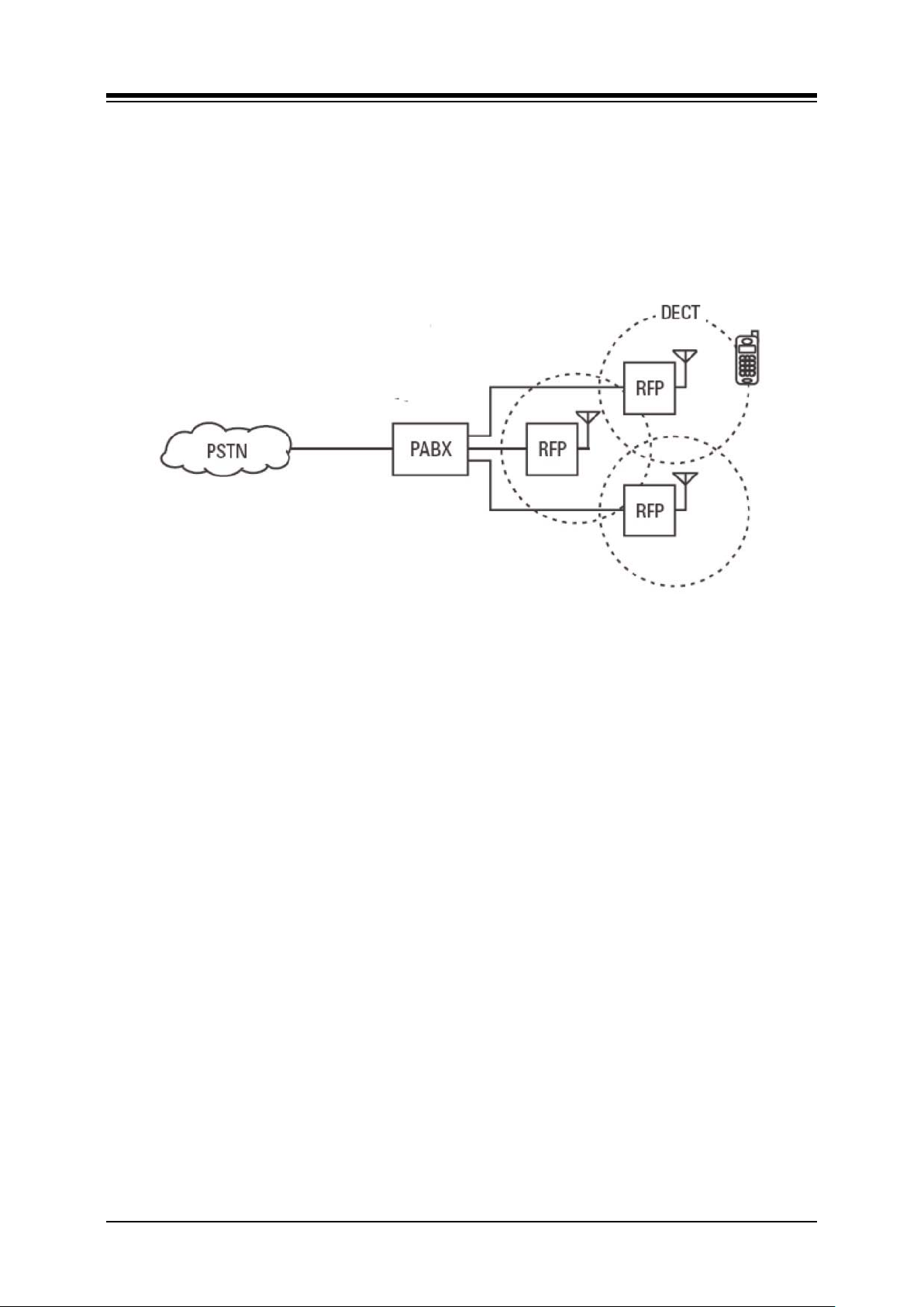
iPECS-MG
Hardware Description and Installation Manual Issue 1.1
5.4.5 WTIB (Wireless Telephone I nt e rf a ce Board) f or DE CT
The WTIB is the iPECS-MG interface to the System DECT solution for in-building mobility with
transparent handover. The WTIB supports European DECT and is not intended for use in other
regions. The System DECT solution is comprised of the 4 or 8 port Wireless Telephone
Interface Boards (WTIB4/8), System DECT Base Stations providing the fixed radio receivers
(cells), and DECT handsets. The figure below is a reference model of the iPECS-MG System
DECT solution.
Figure 5.4.5-1 iPECS-MG DECT Reference Model
The following components make up the System DECT solution:
WTIB4, WTIB8 board – Up to three WTIB4s or WTIB8s can be installed in the
iPECS-MG300, 2 in the MG100 System. The WTIB4 and WTIB8 have 4 or 8 Base
Station ports, respectively.
Base Station (GDC-600B/GDC-600BE) – The System DECT Base Station can
process up to six simultaneous calls. The Base Station is intended for indoor use
only.
Wireless Terminal (GDC-400H/450H) – Up to 192 wireless terminals can be
registered (refer to the DECT Wireless Terminal User Guide). Older versions may
be compatible, check with your local representative.
68
Page 79

iPECS-MG
Hardware Description and Installation Manual Issue 1.1
Table 5.4.5-1 System DECT Base Station Specifications
ITEM SPECIFICATION
Power Feed required +30 VDC
Transmission Max Power 250 mW
Access Method/Duplex TDMA/TDD
Frequency Band 1,880 ~ 1,900MHz
Channel Sp acing 1.728MHz
Modulation GFSK
Data Rate 1.152Mbps
Max. Base S tation distance from the WTIB4/8 600m (twisted 2-pair cable)
Max. T ransmission Power 250 mW
Modulation Method GFSK
Frequency Band 1,880MHz ~ 1,900MHz
The WTIB provides power to the System DECT Base Stations and is the interface between
Base Stations and other resources and features of the iPECS-MG. The iPECS-MG100
supports two (2) WTIBs and the iPECS-MG300 will support three (3) WTIBs. Each port on the
WTIB terminates to an RJ45 connector on the front panel of the board.
69
Page 80
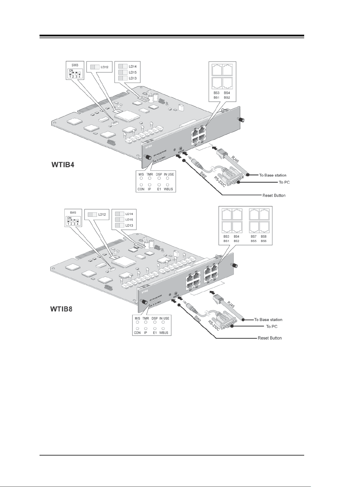
iPECS-MG
Hardware Description and Installation Manual Issue 1.1
Figure 5.4.5-2 WTIB (Wireless Telephone Interface Board)
70
Page 81

iPECS-MG
Hardware Description and Installation Manual Issue 1.1
5.4.5.1 Connectors, Switch and LED Functions
The following Table shows the relation between the front panel RJ45 connectors and
associated Base Station (cell) numbers.
Table 5.4.5.1-1 WTIB RJ45 Connector Functions
CONNECTOR CELL NUMBER
BS1 Cell 1
BS2 Cell 2
BS3 Cell 3
BS4 Cell 4
BS5, WTIB8 only Cell 5
BS6, WTIB8 only Cell 6
BS7, WTIB8 only Cell 7
BS8, WTIB8 only Cell 8
Table 5.4.5.1-2 Switch Functions
SWITCH ON OFF DESCRIPTION DEFAULT
SW3-1 Test mode Normal TRB6 Test Mode OFF
SW3-2 Enable Echo-can. Disable Echo-can. Echo-canceller control ON
SW3-3 Not used ON
SW3-4 All base reset Only new base reset On: All base reset
Off: One base reset
OFF
The nine (9) LEDs mounted on the WTIB indicate the status of the board as explained in the
chart below.
Table 5.4.5.1-3 WTIB LED Indications
LED NORMAL LABEL
1 ON: Master WTIB, Toggle: Slave 1 WTIB, OFF: Slave 2 WTIB M/S
2 When Nios CPU is normal, TMR LED toggles ev ery 100msec. TMR
3 ON: DSP Echo cancellation enabled, OFF: D SP Echo cancellation disabled DSP
4 When more than one DECT channel is used, LED 8 is O N. IN USE
5 When WTIB is connected with MPB, CON LED is ON . CON
6 When WTIB sends or receives data from MPB, IP LED toggles. IP
7 When WTIB sends or receives data from Base Station, E1 LED toggles. E1
8 When WTIB sends or receives data from other WTIB, WBUS LED toggles. WBUS
71
Page 82
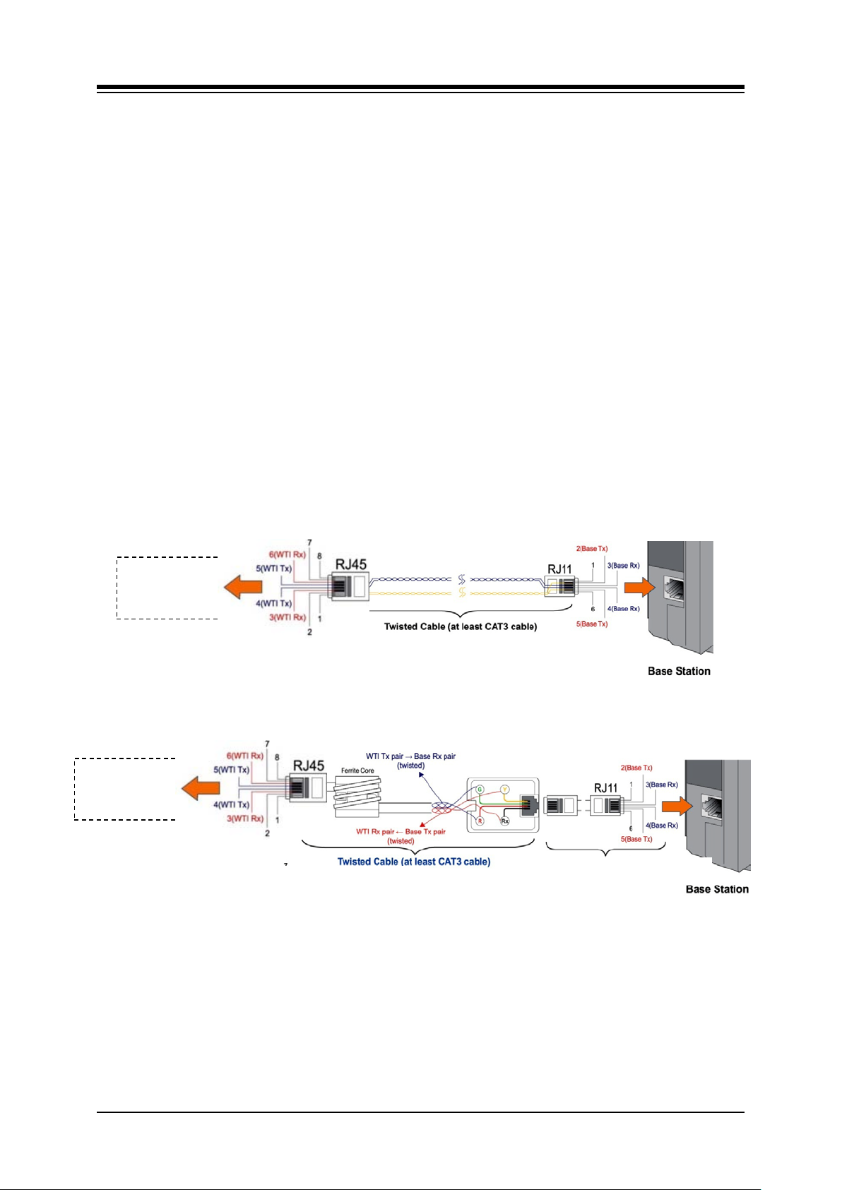
iPECS-MG
WTIB8
WTIB8
Twisted Cable (At least CAT3 cable)
Hardware Description and Installation Manual Issue 1.1
5.4.5.2 DECT Installation
For detailed instructions on Site Planning for Base Stations, Cell-coverage Region Survey,
RSSI Monitoring, and Base Station Installation, refer to the DECT Installation Guide for iPECSMG.
5.4.5.3 WTIB Installation
Prior to installation, assure the Dipswitch settings are in the default position, section 5.4.5.1.
The WTIB can be installed in any universal slot of any KSU; the 1st slot of the BKSU is for the
MPB only. Note when installing more than one WTIB, all WTIBs should be installed in the same
KSU.
Assure Power is OFF.
Slide the WTIB in the guide rails of the desired slot.
Tighten thumbscrews to hold the board firmly in place.
5.4.5.4 Ferrite Core Inst al l at i o n
A ferrite core is provided in the packaging of the System DECT Base Station. When properly
installed, the ferrite core reduces Electro-Magnetic Interference from the Base Station. The
Ferrite core should be installed on each cable that is connected to the WTIB as close to the
WTIB connector as possible. Using RJ45 terminate CAT3 cable, wrap the Ferrite core as
shown in Figure 5.4.5.4-1.
WTIB4 &
WTIB4 &
CAT5 cable provided by Ericsson-LG,
Figure 5.4.5.4-1 WTIB Ferrite Code and Base Station
72
Page 83
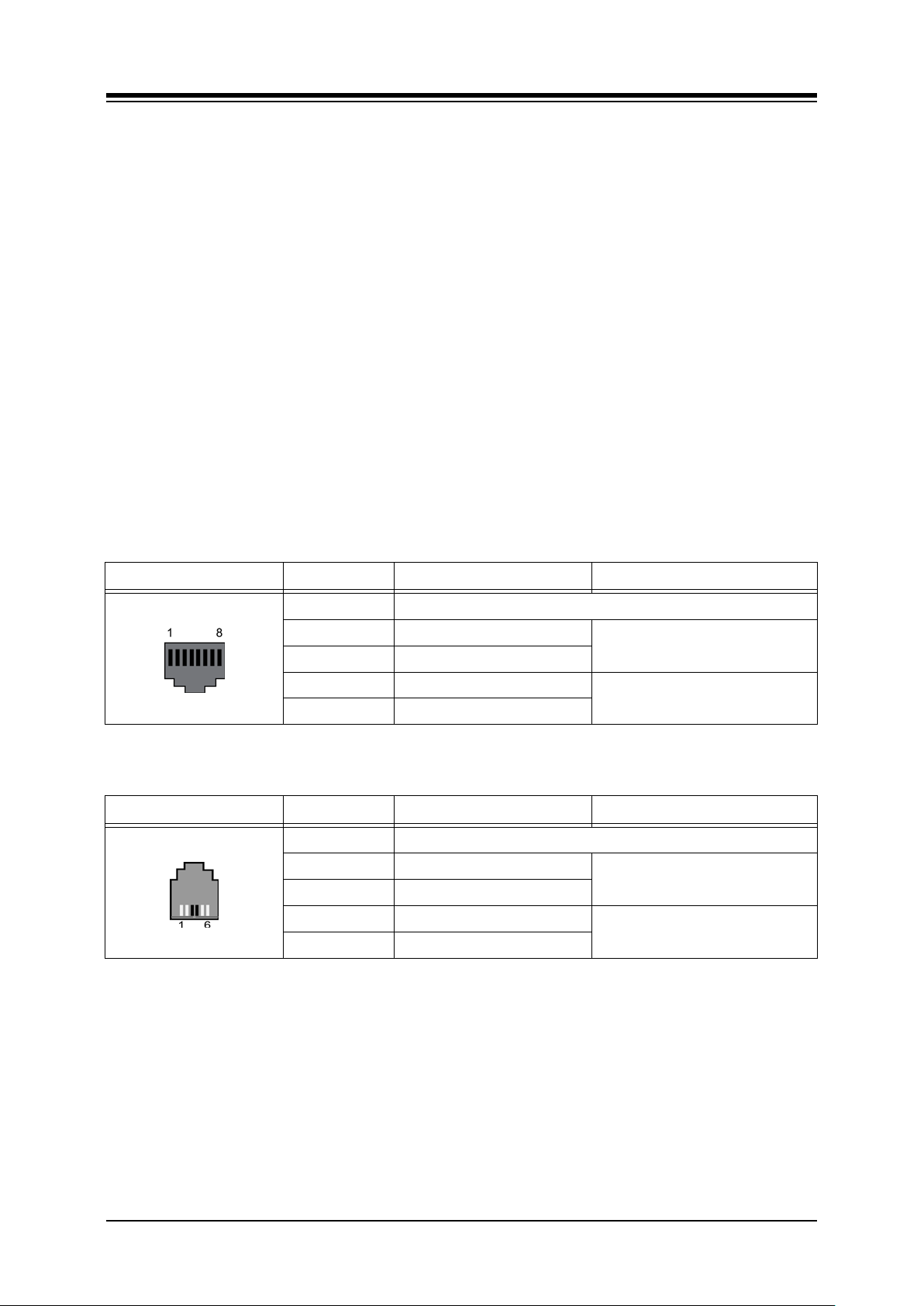
iPECS-MG
Hardware Description and Installation Manual Issue 1.1
5.4.5.5 WTIB Wiring
Each Base Station port on the WTIB is terminated to an RJ45 connector wired as shown in the
pin-out chart below. Separate wiring is required for the TX and RX pairs. Power is delivered
from the WTIB to the Base Station over the simplex circuit formed by the TX and RX pairs.
Referring to the pin-out charts and Figure 5.4.5.5-1 below and Figure 5.4.5.4-1,
Plug RJ45 terminated cable with the Ferrite core into the appropriate WTIB
connector.
Wire each WTIB RJ45 TX and RX pair to the System DECT Base Station
termination point using CAT3 or better wiring. The maximum total wire length is
600M/1.9Kft of 22 AWG.
Tag or number wiring for maintenance.
NOTE
1. A shorter cable length between the WTIB and System DECT Base Stations will
decrease the possibility of data degradation.
2. For best operation, all wiring from the WTIB to the Base Stations should use
unshielded twisted pair wiring (at least Cat 3) of a consistent gauge and kept at the
shortest length possible.
Table 5.4.5.5-1 WTIB Pin -out Chart
CONNECTOR PIN SIGNAL NAME FUNCTION
RJ45 1, 2, 7, 8 Not used
4 TX- & (+30V)
5 TX+ & (+30v)
3 RX+(GND)
6
RX-(GND)
Transmit Dat a & +30V DC pow er
Receive Data & Gnd Power feed
Table 5.4.5.5-2 Base Station
CONNECTOR PIN SIGNAL NAME FUNCTION
RJ45 5, 6 Not used
1 TX+ (GND)
4 TX- (GND)
2 RX+ & (+30V)
3 RX- & (+30V)
Transmit Dat a & G nd P ower feed
Receive Data & +30VDC power
73
Page 84
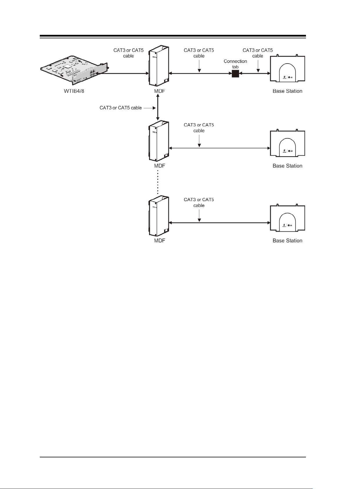
iPECS-MG
Hardware Description and Installation Manual Issue 1.1
Figure 5.4.5.5-1 WTIB Connection to Multiple System DECT Base Stations
5.4.5.6 Serial Port
The VMIB an AAIB include an Audio jack connected to a Serial port. The serial port is used for
diagnostic purposes. For wiring information, refer to section 5.6.
74
Page 85
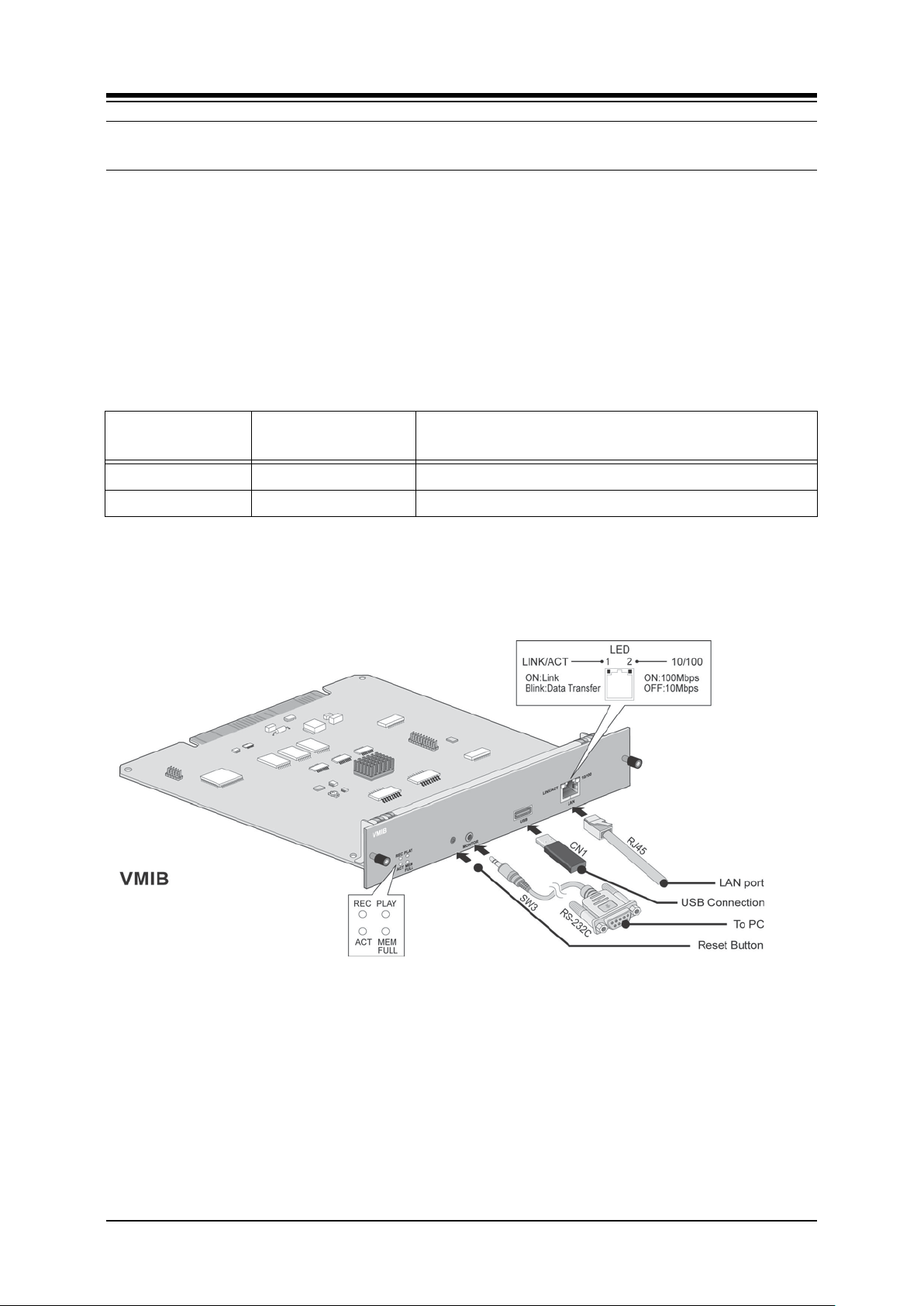
iPECS-MG
Hardware Description and Installation Manual Issue 1.1
5.5 Function Boards
5.5.1 VMIB (Voice Mail Interface Board) and AAIB (Auto-Attendant Interface Board)
The VMIB and AAIB provide memory for System Greetings including CCR and ACD/UCD
announcements. In addition, the VMIB provides memory for User Greetings and Voice
Message storage, 100 hours. The VMIB and AAIB include a processor and DSP circuitry to
support eight (8) simultaneous channels. For additional channels and/or storage capacity, two
(2) VMIBs or AAIBs may be installed in the iPECS-MG100 (16 total channels) and up to three
(3) VMIBs or AAIBs may be installed in the iPECS-MG 300 (24 total channels).
BOARD CHANNEL
VMIB 8 System Greeting (0.5hrs.), User Message (100 Hours)
AAIB 8 System Greeting (0.5hrs.), User Message (None)
SYSTEM GREETING
USER GREETING
The VMIB and AAIB have a standard USB connector that is used to back-up System and User
greetings, and Voice Messages (VMIB only). In addition, the VMIB and AAIB have a LAN and
Audio Serial port jack used for advanced diagnostic purposes and board upgrades only.
Figure 5.5.1-1 AAIB and VMIB
NOTE
If VMIB or AAIB is installed in a System, VMIB/AAIB prompts (Default=1-Eng lish, 2-
3-Blank) should be uploaded for each country.
System Voice prompts are stored on the MPB and not the VMIB or AAIB.
Voice prompt Language can be changed using the Web Admin, VMIB upgrade
function.
75
Page 86

iPECS-MG
Hardware Description and Installation Manual Issue 1.1
5.5.1.1 Switch, and LED Functions
Table 5.5.1.1-1 Switch Functions
SWITCH FUNCTION REMARK
SW1 4-POLE Dip Switch (F unction : not defined) Default: Off
SW2
SW3 Reset switch
SW4
Table 5.5.1.1-2 LED Indication
LED FUNCTION REMARK
LD1 Normal operation indication (Activity Indication) Blink (blue Color)
LD2 Memory Full (ON – Full, OFF – Usable) AAIB – Not used
LD3 Record (ON – Active, OFF – Idle)
LD4 Play (ON – Active, OFF – Idle)
RJ45-LD1
(Green/Orange)
RJ45-LD2 (Yellow) ON - 100Mbps, OFF – 10Mbps
ON – Link, Blink – Data Transfer
5.5.1.2 VMIB and AAIB Installation
The VMIB and AAIB have no switches or connectors that are field useable. The VMIB and
AAIB can be installed in any universal slot of any KSU; the 1st slot of the BKSU is for the MPB
only. A maximum of two boards may be installed in the iPECS-MG100 and three (3) in the
iPECS-MG300.
Assure Power is OFF
Slide the VMIB/AAIB in the guide rails of the desired slot.
Tighten thumbscrews to hold the board firmly in place.
5.5.1.3 VMIB and AAIB Wiring
There is no wiring required for proper operation of the VMIB or AAIB.
76
Page 87
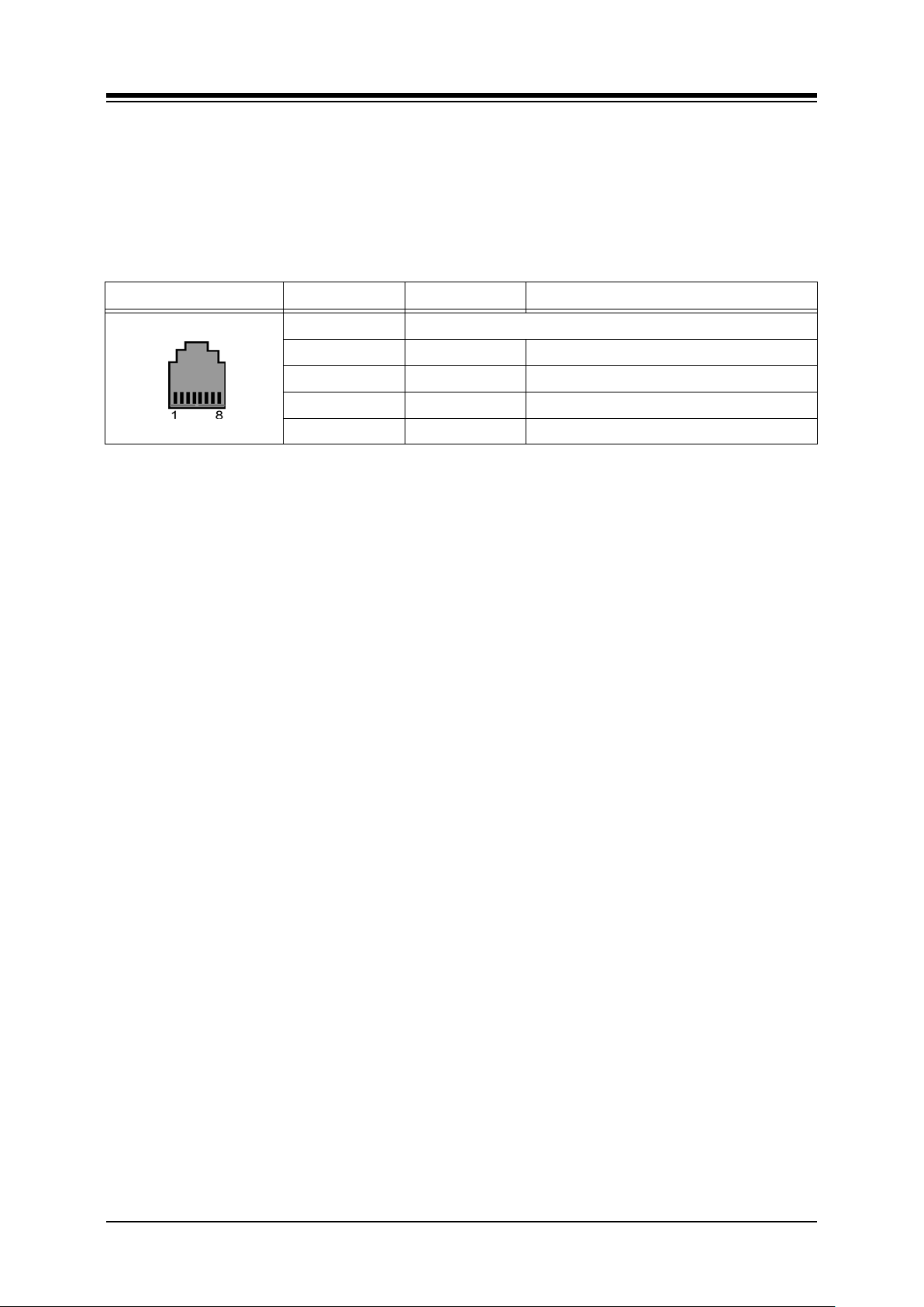
iPECS-MG
Hardware Description and Installation Manual Issue 1.1
5.5.1.4 VMIB and AAIB LAN Connector
The VMIB and AAIB include an RJ45 for connection to a 10/100 Base-T Ethernet (IEEE 802.3)
connection. The port supports auto negotiation for speed (10 or 100 Mbps) and full or halfduplex operation. If need be, the RJ45 is wired as indicated in the RJ45 pin-out chart below.
Table 5.5.1.4-1 VMIB & AAIB RJ45 Pin-out Chart
CONNECTOR PIN SIGNAL NAME FUNCTION
RJ45 4,5,7,8 Not used
1 TX+ Transmit Data
2 TX- Transmit Data
3 RX- Receive Data
6 RX+ Receive Data
5.5.1.5 Serial Port
The VMIB an AAIB include an Audio jack connected to a Serial port. The serial port is used for
diagnostic purposes. For wiring information, refer to section 5.6
77
Page 88
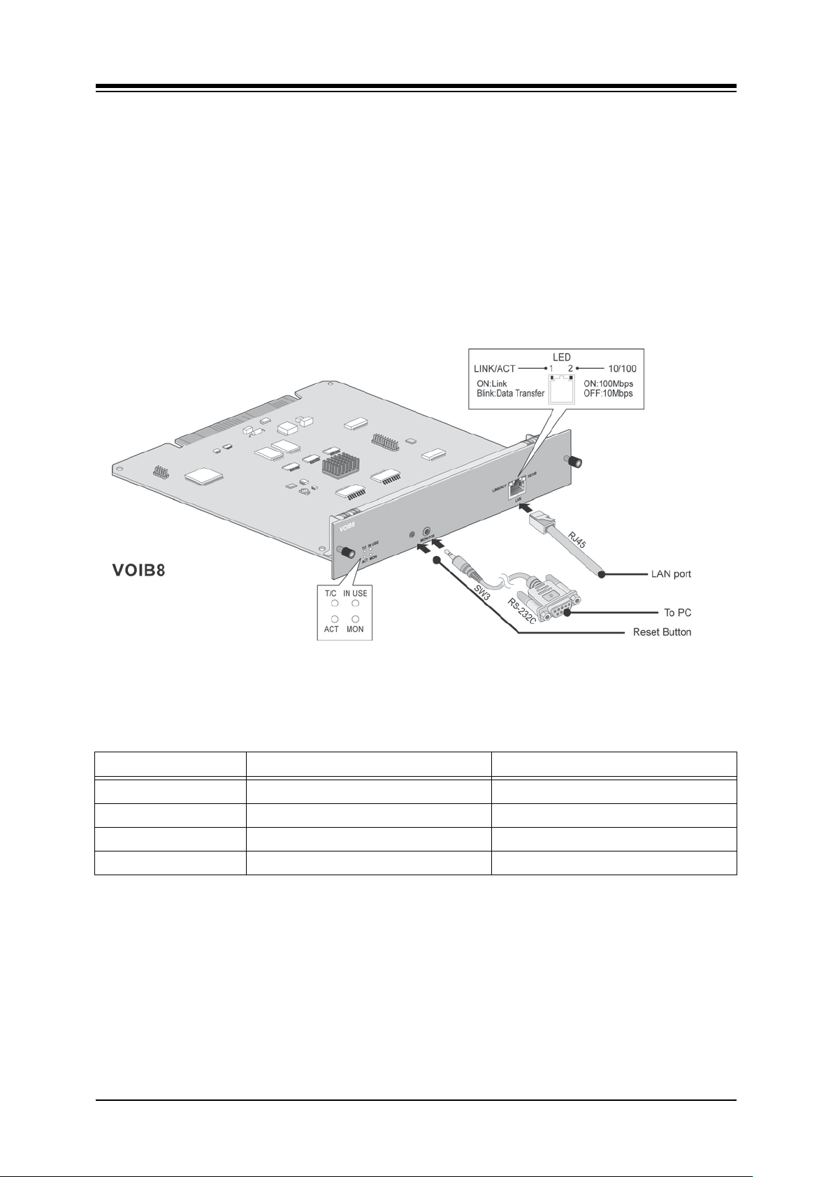
iPECS-MG
Hardware Description and Installation Manual Issue 1.1
5.5.2 VOIB (Voice over Internet protocol Board, 8 and 24channel)
The VOIB is available in two (2) models, the VOIP8 with 12 IP channels and the VOIB24 with
24 IP channels. Other than the number of channels, there are no significant differences in the
VOIB8 and VOIB24. The VOIB provides the Ethernet interface for Ericsson-LG IP Phones, SIP
phones and trunks, IP Networking and applications. The VOIB is used to provide packet relay
for remote devices to communicate with the host and translate between the iPECS proprietary
protocols and other standard protocols (H323 rev.4, SIP RFC3261).
The VOIB connects to a standard IEEE 10/100 Base-T Ethernet switch port and supports auto
negotiation for speed (10MBps or 100Mbps) and full or half-duplex operation. The VOIB
supports various codecs (g.711, g.726, g.729, g.723.1), T.38 for IP FAX, and Echo Cancellation
(g.168).
Figure 5.5.2-1 VOIB8
5.5.2.1 Switch and LED Functions
Table 5.5.2.1-1 Switch Functions
SWITCH FUNCTION REMARK
SW1 4-Pole Dip-switch (Function : n ot defined) Default : Off
SW2
SW3 Reset switch
SW4
78
Page 89
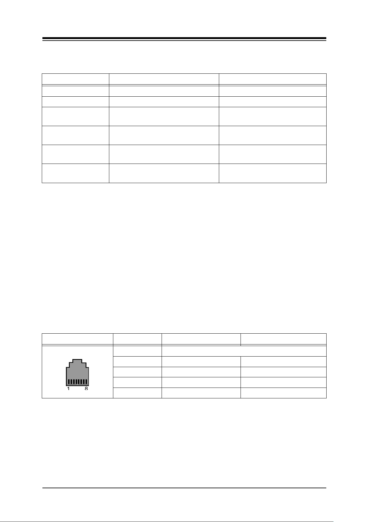
iPECS-MG
Hardware Description and Installation Manual Issue 1.1
Table 5.5.2.1-2 LED Indication
LED FUNCTION REMARK
LD1 VOIB Task Active (CMD/Event Processing) Blink (Blue Color)
LD2 Trace T ask Active (Line Monitor ) Blink (Blue Color)
LD3 Transcoding
LD4 Active VOIP call (Channel in use)
RJ45-LD1
(Green/Orange)
RJ45-LD2
(Yellow)
Data Link
Port speed
On: T ranscoding in use
Off – T r anscoding not in use
On: Channel in use,
OFF: All channels Idle
On Link - established
Blink – Data transfer
On – 100 Mbps
Off – 10 Mbps
5.5.2.2 VOIB Installation
The VOIB Dip switches should be set to the OFF position before installation. To install the
VOIB,
Assure Power is OFF
Slide the VOIB in the guide rails of the desired slot.
Tighten thumbscrews to hold the board firmly in place.
5.5.2.3 VOIB Wiring
The VOIB is connected to the LAN through the RJ45 connector on the front panel. The
connector is terminated as a standard EIA 568B MDI (Media Dependent Interface) port.
Referring to the pin-out chart below,
Using UTP cable, wire each VOIB TX and RX pairs to the termination point of an
Ethernet switch port RX and TX pairs, respectively.
Table 5.5.2.3-1 VOIB LAN PORT
CONNECTOR PIN SIGNAL NAME FUNCTION
RJ45 4,5,7,8 Not used
1 TX+ Transmit Data
2 TX- Transmit Data
3 RX- Receive Data
6 RX+ Receive Data
5.5.2.4 Serial Port
The VOIB include an Audio jack connected to a Serial port. The serial port is used for
diagnostic purposes. For wiring information, refer to section 5.6.
79
Page 90
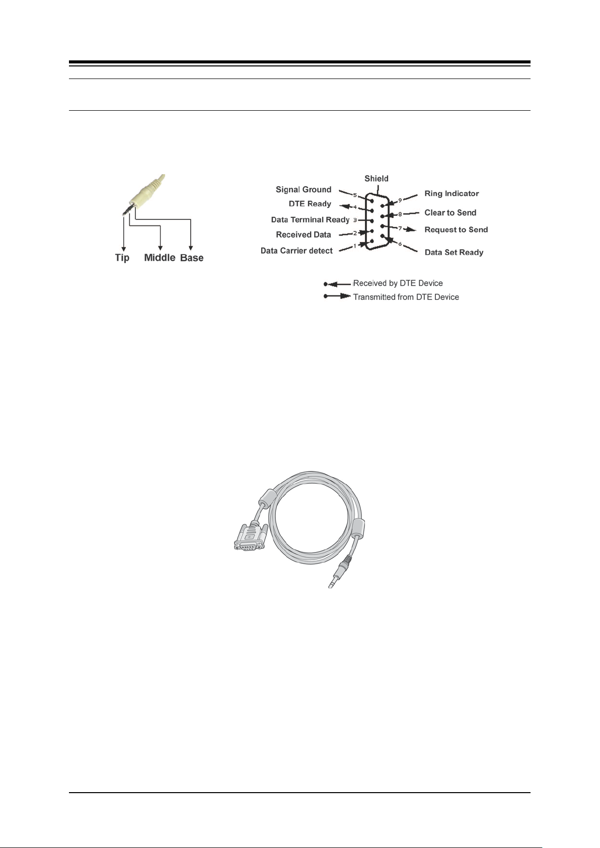
iPECS-MG
Hardware Description and Installation Manual Issue 1.1
5.6 Serial to Audio Cable Specification
Several board types include a serial port presented as an Audio jack. This serial port is not
required for normal operation, it is only used for advanced diagnostics. Boards that include the
Audio Serial connector are PRIB, BRIB2/ BRIB4, AAIB/VMIB, V OIB , a nd WTIB.
Figure 5.6-1 Audio Jack, Serial Specification
5.6.1 Serial to Audio Cable Wiring
Connection to the Serial port through the Audio connector is made with a Serial to Audio cable.
The cable should be terminated on one end with a DB9 RS-232 connector and on the other
end with an audio jack. The three (3) wires of the audio jack are wired to the DB9 as follows.
Wire the Tip conductor of the Audio jack to pin 2 of the DB9
Wire the Ring conductor of the Audio jack to pin 3 of the DB9
Wire the Grd conductor of the Audio jack to pin 5 of the DB9
Figure 5.6.1-1 Audio Jack to Serial Cable
80
Page 91
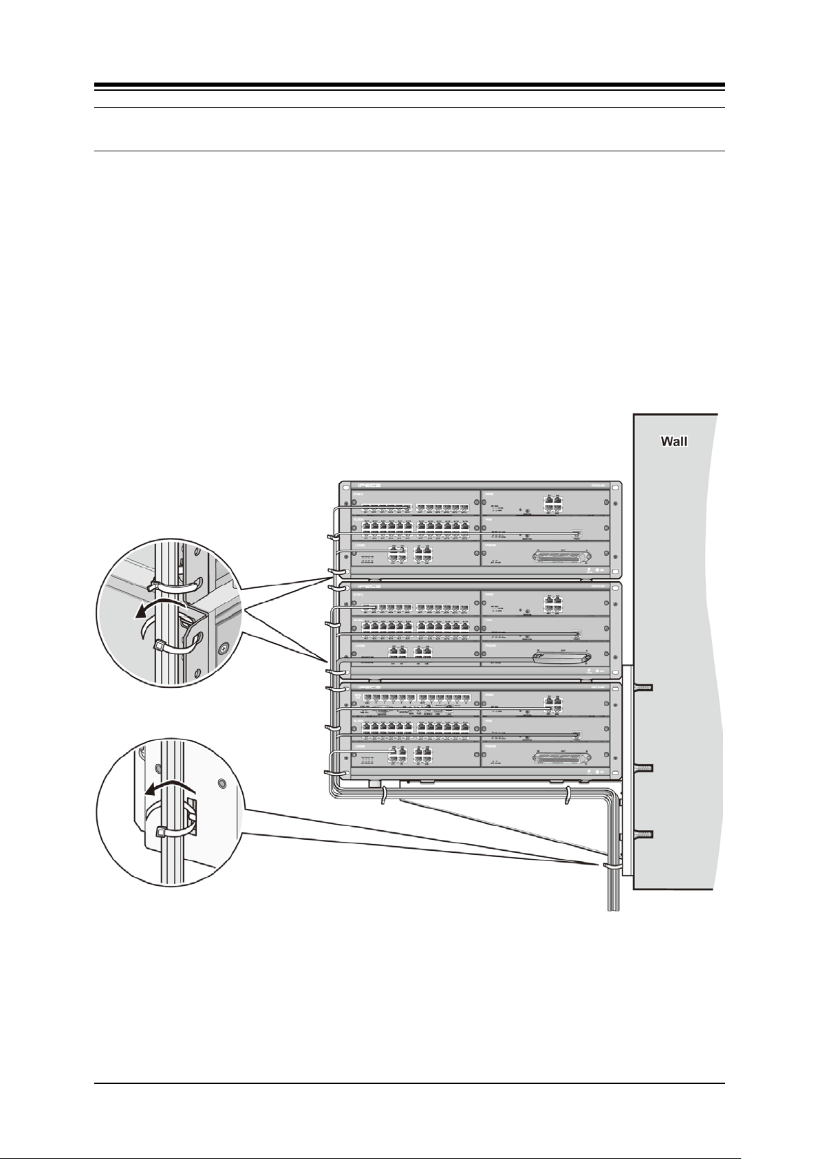
iPECS-MG
Hardware Description and Installation Manual Issue 1.1
5.7 Cable Dressing
To provide a neat professional installation, the wiring to the KSU(s) should be dressed. The
wiring cables should be bundled and tie wrapped to the KSU(s) and to the wall or rack.
5.7.1 Wall Mount Wiring
To dress wiring for a Wall mount installation,
1. Ensure all boards are installed and that wiring is complete.
2. Using the supplied Cable Ties, tie all wiring cables and Power cord (if desired)
together in a neat bundle.
3. Using the supplied Cable Ties, tie the bundled cables to a Rack Mount bracket.
4. Dress the cable bundle under the bottom KSU and attach to the wall at regular
spacing back to the wiring termination point.
Figure 5.7.1-1 Wall Mount Wiring
81
Page 92
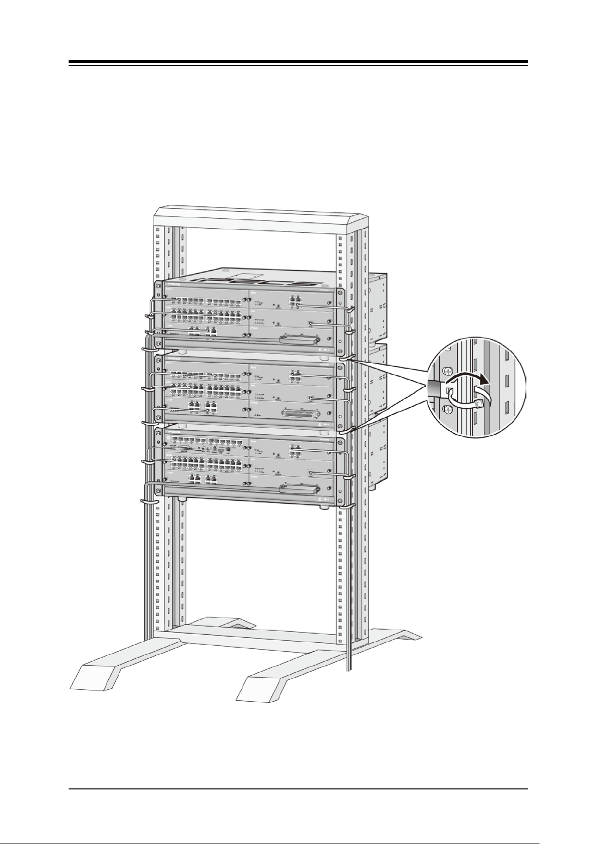
iPECS-MG
Hardware Description and Installation Manual Issue 1.1
5.7.2 Rack Mount Wiring
To dress wiring for a Rack mount installation,
1. Ensure all boards are installed and that wiring is complete.
2. Using the supplied Cable Ties, tie all wiring cables and Power cord (if desired)
together in a neat bundle.
3. Using the supplied Cable Ties, tie the bundled cables using holes in the 19” Rack.
4. Dress the cable down the rack back to the wiring termination point.
Figure 5.7.2-1 Rack Mount Cable Dressing
82
Page 93

iPECS-MG
Hardware Description and Installation Manual Issue 1.1
6. TERMINAL CONNECTION AND WIRING
6.1 Terminal and Door Phone Models
Various types of digital terminals and IP Terminals can be used with the iPECS-MG as listed in
the table and shown below. Other older model digital phones may also be compatible with the
iPECS-MG, check with your local Ericsson-LG representative for details.
Digital Key Telephones connect to the DSIU or a DTIB. IP Key Telephones connect to the LAN
where they have access to a VOIB channel.
MODEL DESCRIPTION
LDP-7004N 4 Flexible Button No display
LDP-7004D 4 Flexible Button w/Display
LDP-7008D 8 Flexible Button w/Display
LDP-7016D 16 Flexible Button w/Display
LDP-7024D 24 Flexible Button w/Display
LDP-7024LD 24 Flexible Button w/Large Display
LDP-7048DSS 48 Button DSS/DLS Console
LDP-DPB Door Phone Box
LIP-7008D 8 Flexible Button w/Display
LIP-7016D 16 Flexible Button w/Display
LIP-7024D 24 Flexible Button w/Display
LIP-7024LD 24 Flexible Button w/Large Display
LIP-8002 4 Feature Button w/Display
LIP-8004D 4 Flexible Button w/Display
LIP-8008D 8Flexible Button w/Display
LIP-8012D 12 Flexible Button w/Display
LIP-8024D 24 Flexible Button w/Display
LIP-8040L 10 Flexible Button w/Large Display
LIP-8012DSS 12 Button DSS Console / Pow er supply
LIP-8012LSS 12 Button LSS Console / via keyset up to 2
LIP-8048DSS 48 Button DSS Console / via ex ternal up to 4
LIP-8040LSS 48 Button DSS Console w/Display via external or PoE up to 9
LIP-8002E/2AE 4 Feature Button w/Display
LIP-8008E 8 Flexible Button w/Display
LIP-8012E 12 Flexible Button w/Display
LIP-8024E 24 Flexible Button w/Display
LIP-8040E 10 Flexible Button w/Large Display
LIP-8050V 5 Flex ible B utton, w /C olor D isplay & Video Camera
83
Page 94
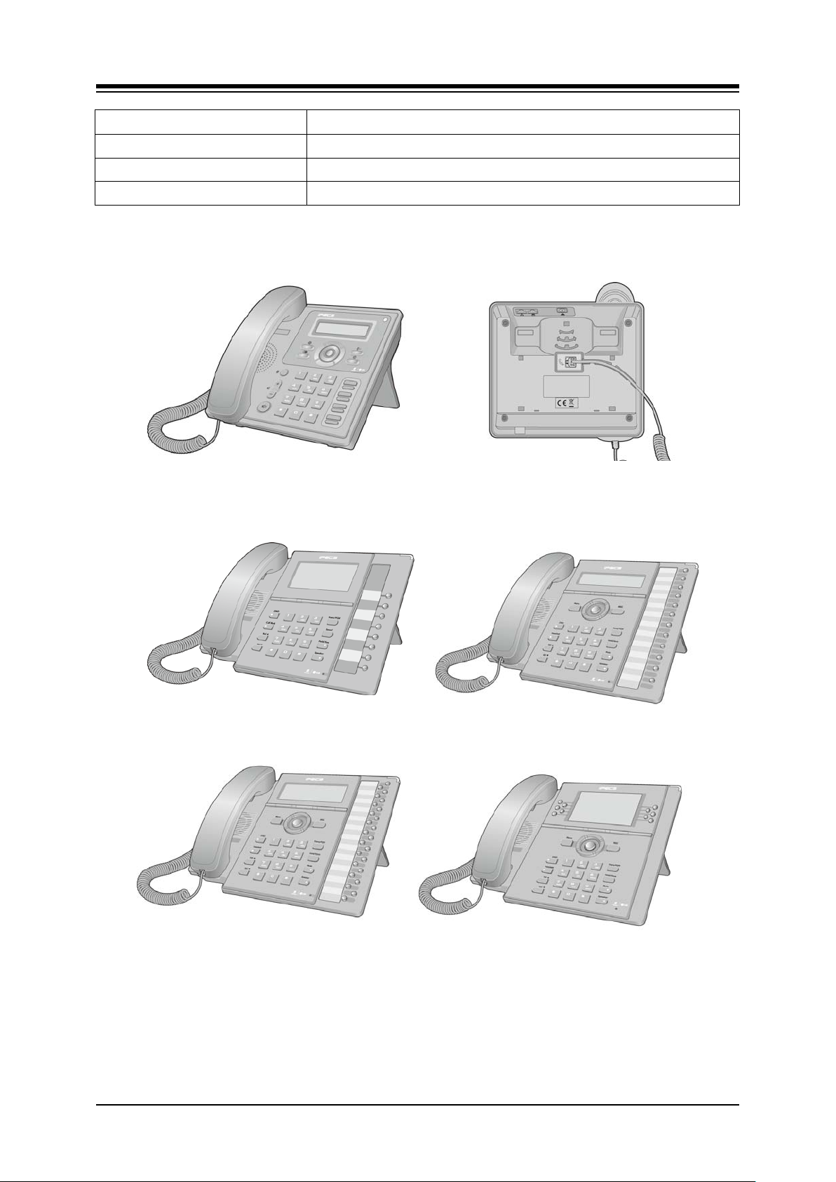
iPECS-MG
Hardware Description and Installation Manual Issue 1.1
MODEL DESCRIPTION
LDP-9008D 8 Flexible Button w/Display
LDP-9030D 30 Flexible Button w/Display
LDP-9048DSS 48 Button DSS Console
LIP-8008E
LIP-8002E/2AE
LIP-8012E
LIP-8024E LIP-8040E
Figure 6.1-1 LIP 8000E Series Keysets
84
Page 95
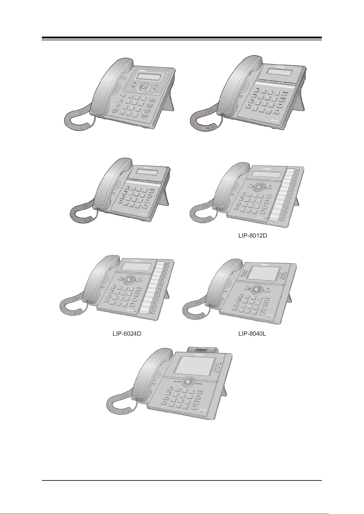
iPECS-MG
Hardware Description and Installation Manual Issue 1.1
LIP-8002 LIP-8004
LIP-8008D
LIP-8050V
Figure 6.1-2 LIP-8000 Series Keysets
85
Page 96
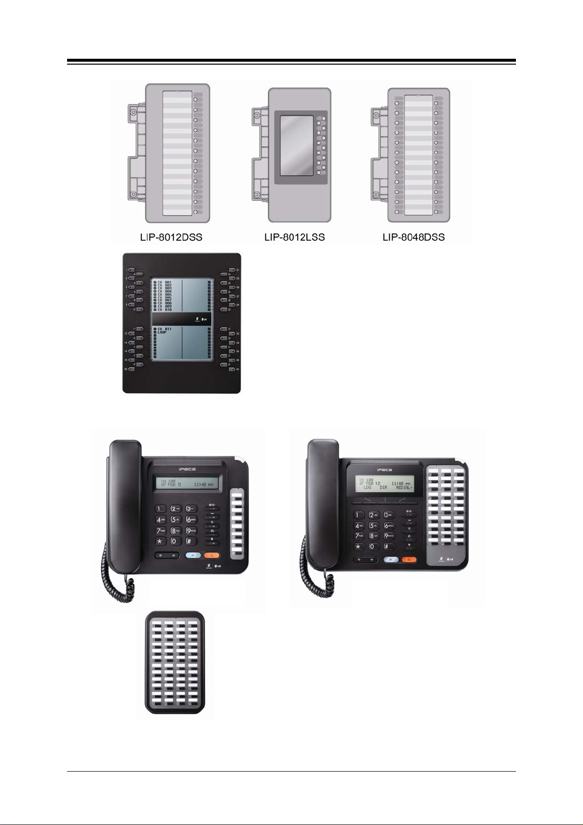
iPECS-MG
Hardware Description and Installation Manual Issue 1.1
LIP-8048LSS
Figure 6.1-3 LIP-8000 Series DSS & LSS
LD-9008D LD-9030D
LD-9048SS
Figure 6.1-4 LDP-9000 Series Keysets
86
Page 97
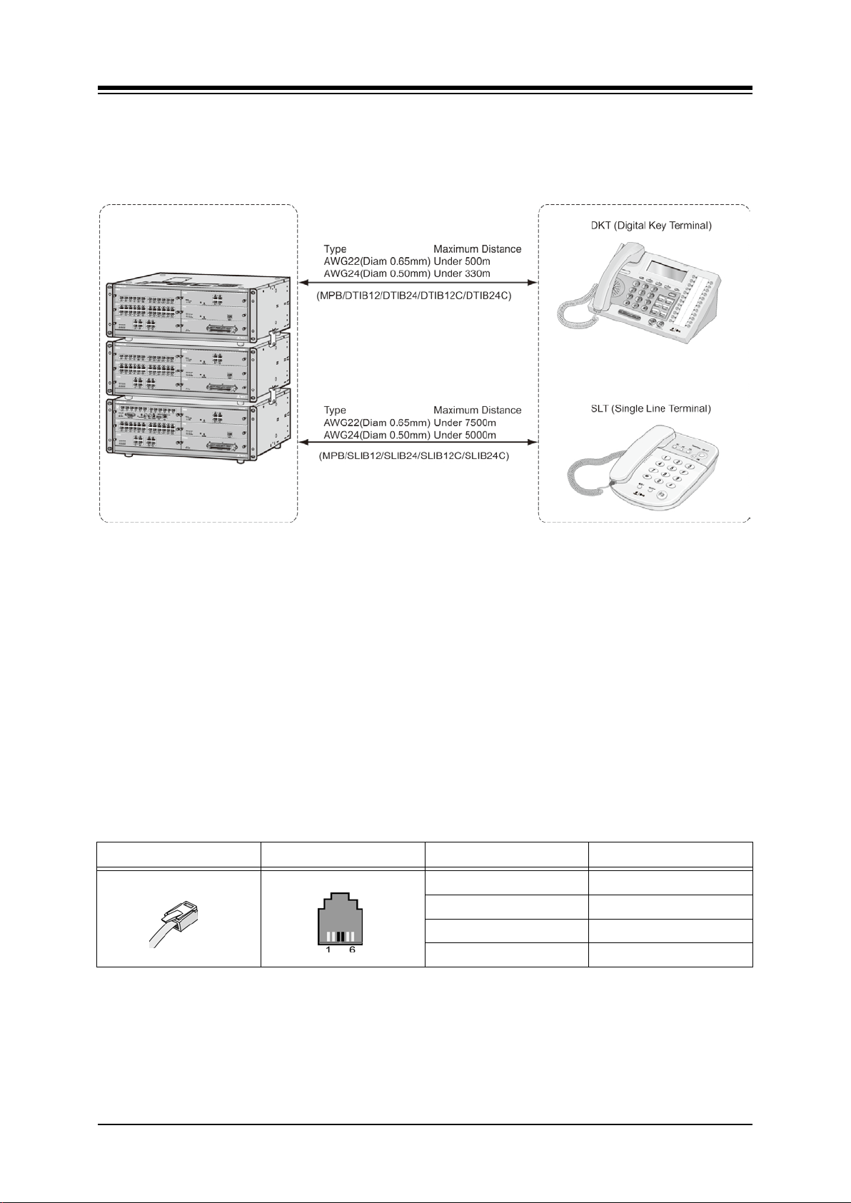
iPECS-MG
Hardware Description and Installation Manual Issue 1.1
6.1.1 Terminal Cabling Distance
Figure 6.1.1-1 Terminal Cabling Distance
6.1.2 Terminal Connections
6.1.2.1 DKT Wiring
The Digital Key Telephone and digital DSS Console are terminated to the 1st pair of the RJ11
located in the bottom of the DKT or Console. The wall outlet for the DKT or Console should be
connected back to an appropriate DTIB or MPB DSIU DKT port.
Referring to the pin-out chart below and Figure 6.1.1-1,
Wire the wall outlet 1st pair to the DTIB or DSIU termination point using UTP cable.
Note separate wiring is required for the LDP-7048 DSS Console.
Using the line cord provided, connect the DKT or DSS Console to the wall outlet.
Table 6.1.2.1-1 DKT Pin-out Chart
Line Cord CONNECTOR PIN SIGNAL NAME
RJ11 1,2 Not used
3 Ring
4 Tip
5,6 Not used
87
Page 98
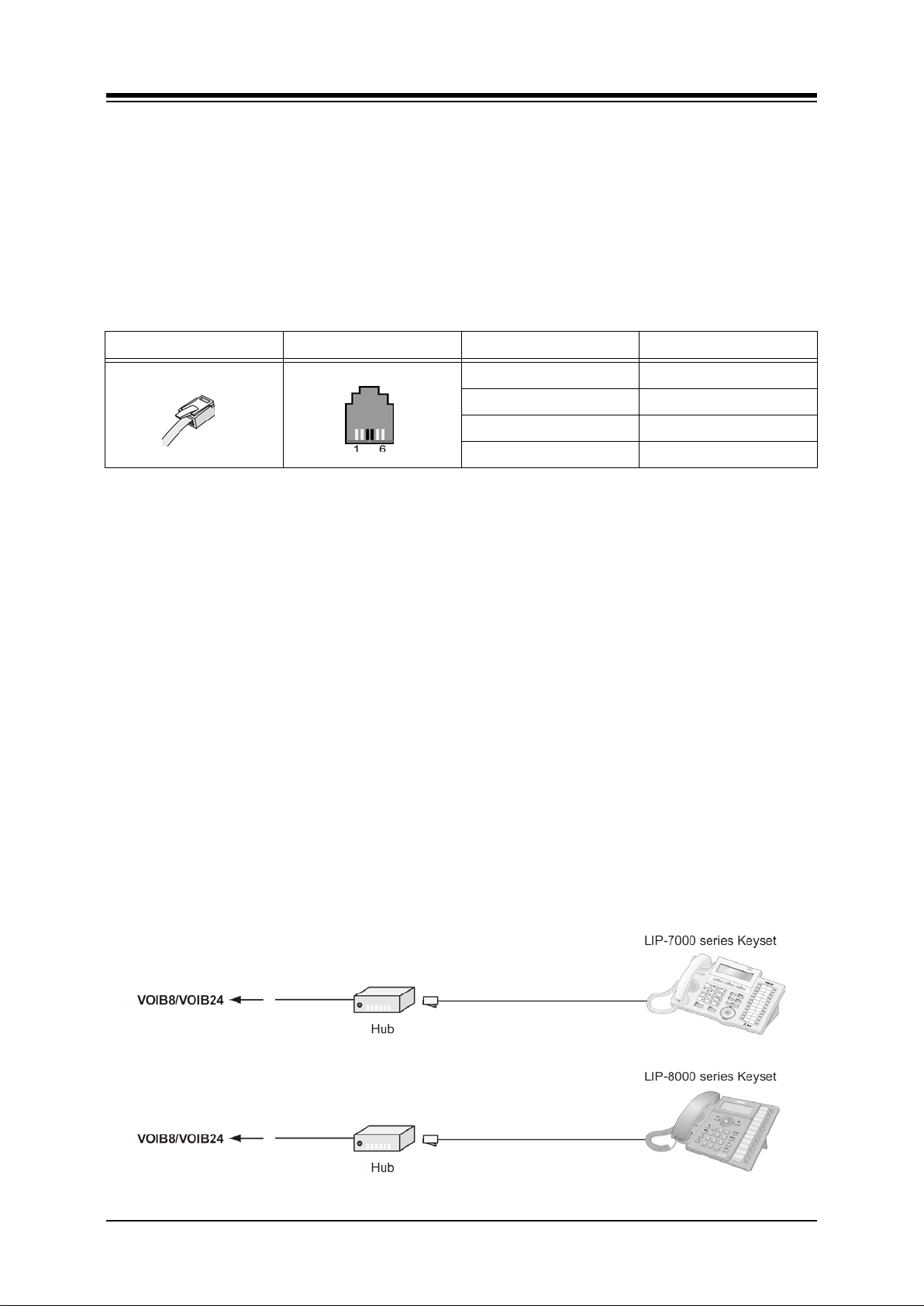
iPECS-MG
Hardware Description and Installation Manual Issue 1.1
6.1.2.2 SLT wiring
SLTs are wired to the center pair of the RJ11, typically on the bottom or back of the SLT. The
wall outlet should be connected back to an appropriate SLIB or DSIU SLT port.
Referring to the pin-out chart below and Figure 6.1.1-1,
1. Wire the center pair of the wall outlet to the SLIB or DSIU termination point using UTP
cable.
2. Using the line cord provided with the SLT, connect the SLT to the wall outlet.
Table 6.1.2.2-1 Standard SLT Pin-out Chart
Line Cord CONNECTOR PIN S IGNAL NAME
RJ11 1,2 Not used
3 Ring
4 Tip
5,6 Not used
6.1.2.3 LIP-7000 & LIP-8000 & 8000E Series Keyset Wiring
The iPECS-MG supports the LIP-7000 and 8000 series IP Phones. The LIP-7008D and the
LIP-8004D have a single LAN port that is wired to an Ethernet switch port. All other LIP-7000
and 8000 & 8000E series phones shown here have two (2) Ethernet ports, a LAN port and a
PC port. The LAN port is connected to an Ethernet switch port and the PC port is connected to
the LAN port of a PC. The LIP phones are wired to any 10/100 Base-T Ethernet switch port
with access to a VOIB channel. The LIP phones can be powered from a POE compatible
Ethernet switch port or using the AC/DC Adaptor-K.
Referring to Figure 6.1.2.3-1 and the IP Phone pin-out chart below,
Wire the RX and TX pins from the RJ45 Wall outlet, or equal, for the IP Phone to the
appropriate Ethernet switch termination point using Cat 5 UTP cable. The maximum
wire length between the IP Phone and the Ethernet switch port is 100m or 328 feet.
Use the RJ45 terminated cable provided with the phone to connect the IP Phone to
the Wall outlet.
Connect the PC port to a PC LAN port using a CAT 5 cable terminated on each end
with an RJ45 connector.
If not using a POE switch port, connect the DC connector of an AC Adaptor-K to the
DC input on the bottom of the IP Phone and plug the AC plug of the AC adaptor in
to a 100-240 VAC outlet.
Figure 6.1.2.3-1 LIP Phone Connection
88
Page 99

iPECS-MG
Hardware Description and Installation Manual Issue 1.1
Table 6.1.2.3-1 IP Phone Pin-out Chart
CONNECTOR PIN SIGNAL NAME FUNCTION
RJ45 4,5,7,8 Not used
1 TX+ Transmit Data
2 TX- Transmit Dat a
3 RX- Receive Data
6 RX+ Receive Data
6.1.3 LDP Door Phone Box
The iPECS-MG supports the LDP DPB, digital Door Phone Box. The Door Phone Box can
place a call to assigned stations and a station can answer the Door Phone Box call. If
configured, the station user can activate a door-lock release mechanism to allow entry.
6.1.3.1 Door Phone Box Installation
The Door Phone Box can be wall mounted in a protected environment; the DPB is not intended
for exterior application. To wall mount the LDP-DPB,
Locate the mounting position for the Door Phone Box,
Mark position for two (2) screws
Drill holes for two (2) plastic anchors
Insert screws and tighten leaving about ¼ inch exposed.
Align the screw holes in the back of the LDP-DPB with the screws and slide down to
lock in place. It may be necessary to remove the box and loosen or tighten the
screws for a secure fit.
6.1.3.2 Door Phone Box Wiring
The Door Phone Box is wired using screw terminals in the box. The terminals are wired to any
available DKT port except for the first DKT port.
Refer ring to F i gure 6.1.3.2-1 and the pin-out chart below,
Loosen the screw holding the Door Phone Box cover.
Loosen the two (2) screw terminals.
Using a UTP cable terminated on one end with an RJ11, strip approximately ¼ inch
of insulation from the center pair at the un-terminated end of the wire.
Insert the DKT Tip in one terminal and the DKT Ring.
Tighten the screws to connect and securely fasten the wires.
Plug the terminated end of the wire into a standard wall outlet with an RJ11.
Wire the wall outlet 1st pair to the DTIB or DSIU termination point using UTP cable.
89
Page 100
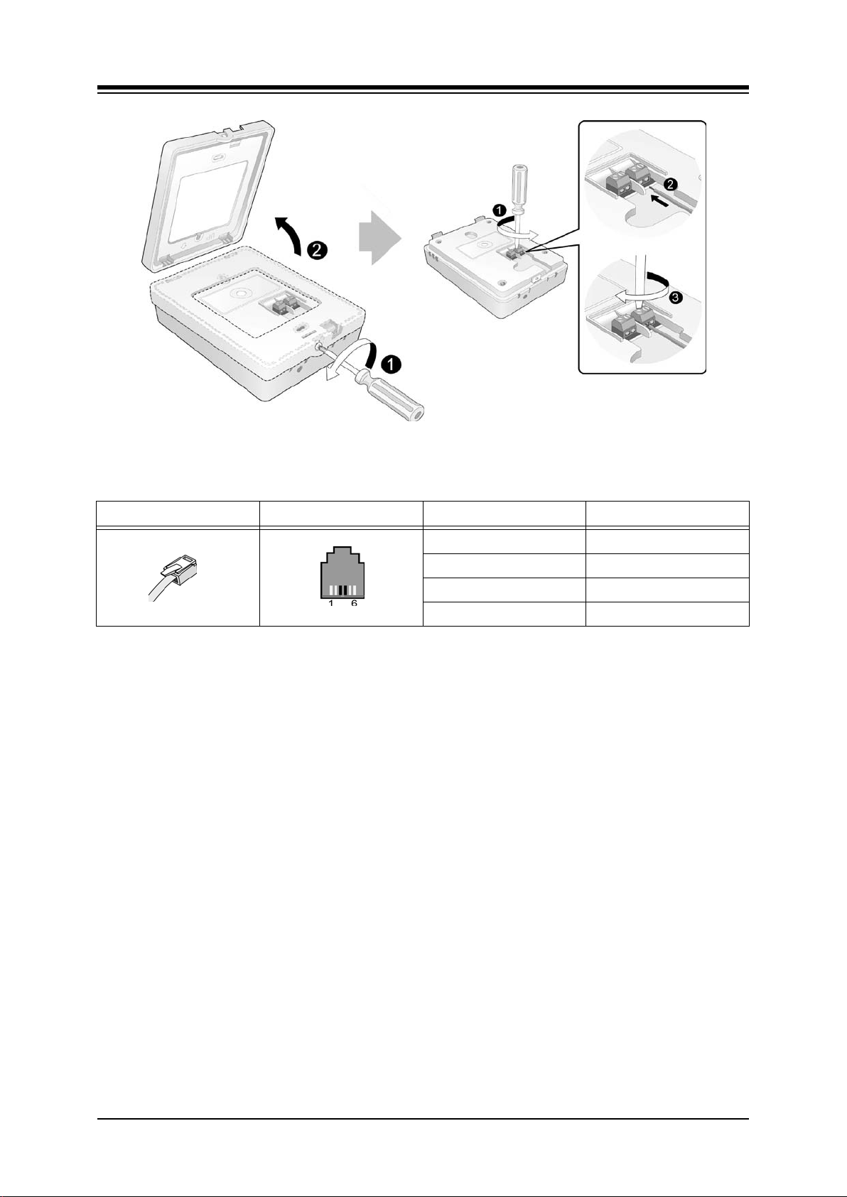
iPECS-MG
Hardware Description and Installation Manual Issue 1.1
Figure 6.1.3.2-1 Door Phone Box Wiring
Table 6.1.3.2-1 LDP-DPB Pin-out Chart
Line Cord CONNECTOR PIN SIGNAL NAME
RJ11 1,2 Not used
3 Ring
4 Tip
5,6 Not used
90
 Loading...