

Page 1

iPECS eMG80 & eMG800 & UCP
Administration & Programming
Manual
Please read this manual carefully before operating System.
Retain it for future reference.
Page 2

iPECS eMG80 & eMG800 & UCP
1.0
Sep., 2013
Initial Release
1.1
Dec., 2013
Changed Ericsson-LG to Ericsson-LG Enterprise
1.1.x
1.2
Feb., 2015
Update contents according to S/W integration for both eMG80 & eMG800
- Add System Date and Time to Installation wizard
- Added Alarm mode to send email to the address in PGM 163.
Administration and Programming Manual Issue 1.6
Revision History
SW version ISSUE DATE DESCRIPTION OF CHANGES
1.2.x 1.3 May, 2015 We updated the following features:
- On-line user guide
- Terminal attributes (Small popup use, large popup timer, SLT open
loop time)
- Web Access Authorization
- NTP attributes
- Digit Conversion Table
- System attributes
- U-LOOP, PBX code insertion for emergency call
- Disconnect with Inband information
- Temp License expiration notify
- Trace Log via Web
2.0.x 1.4 Jan., 2016 - Added Speed code number plan in PGM100.
- IPCR announce only for incoming call.
- Updated Strong password in PGM 160/161.
- Updated ‘Do not overwrite station name in PGM 211.
- Added Attendant ring mode in PGM 257.
- Added the more item for Alarm in PGM 163.
- Added Flexible button default table (PGM 239)
- Added Preset flexible button default (PGM 240)
- Added System DST mode in PGM 439.
- Added LDAP server setting in PGM 160/161.
- Added Arabic language.
- Updated Message wait indication LED in PGM 112.
- Updated Company directory in Station Name Display.
- Added Station User Greeting in Station Data.
- Added the search box in Maintenance.
- Added MOH Management in Maintenance.
- Updated DB management by adding Comment field.
- Updated Install wizard
- DTMF repeat tone does not have nothing to do with PSTN in
PGM160-15
- Added Call wait signal and duration in PGM 113.
- Added some admin (Alternate/Secondary signal port, Local route ID,
Remote route ID, Sending Name option) in PGM 324.
- Added SLT Pulse and SLT pulse-MW type in PGM 110.
- Added Lift Handset for Page & Privacy in PGM 111.
- Added Short Modem in PGM 112.
- Added NFC Authorization Code use in PGM 112.
- Added rel 180 after 183 and “Add ‘user=phone’ param” in PGM 133.
- Added Short Modem Timer in PGM 182~182, 186
Page 3

iPECS eMG80 & eMG800 & UCP
- Added Keyset admin password to Install Wizard.
2.0.x
1.5
April, 2016
- ‘Unified SMB A&P manual’ by integrating eMG and UCP.
- PGM 115/129 : Flexible Buttons
Administration and Programming Manual Issue 1.6
- Added the special character to DB management.
- Added Ring detection register setting in Analog parameter.
- Added LCD Dimming for LIP-9000 Series & LDP-9240D in PGM 112.
- ‘Go to assignment’ function added to Personal group overview and
can check the master & member list at a glance.
- Added Station ICR scenario (1201) to Station Data.
- Changed the name from UCS Standard to UCS data.
- Added MOH management in Maintenance.
2.1.x 1.6 August, 2016 - The type of Speed numbering is added more in PGM 100.
- ‘DDNS usage of Firewall’ & ‘Domain name of Firewall’ is added in
PGM 102.
- The LCD LED is changed to the option ‘MWI/Ring’ or ‘Ring’.
- The ACD & CRM function is added for UCS Client: CRM function
and ACD login/out & ACD On/Off duty in PGM 112.
- UCS Dialing Rule Use for Standard UCS in PGM 112.
- UCS Mobile Dial Use (Android) for Standard UCS in PGM 112.
- The description of CLI Name Display is changed, refer to PGM 113.
- Display full CLI function is added in PGM 113.
- SMTP Server Address fills out up to 64 characters in PGM 127.
- Proxy Server Address fills out up to 64 characters in PGM 133.
- The range for ICLID Usage is changed to Disable, CLI, Name/CLI in
PGM 140.
- Web hacking block is added in PGM 160; Web admin login failure
count to block, Web admin hacking block period, Wed admin
hacking Email notification.
- UCS Ring ACK count is added in PGM 160 and UCS Ring ACK
timer is added in PGM 180.
- SLT Line monitor and SLT Line Monitor time is added in PGM 160.
- Dial Back to Caller from Remote VM Access is added in PGM 160.
- Alarm Display is added in PGM 163.
- The range about Alarm is changed to Off, On, Alarm only,
Alarm/Email. Especially, the default of Maintenance Expire Notify is
Email only.
- Message wait (Call back) for LED flash is added in PGM 170.
- Outgoing Call type is added for All call or Answered call in PGM 177.
- Call log/Directory Auto Idle Timer is added in PGM 180.
- The range of Hot Desk for eMG and UCP is changed in PGM 250:
eMG80 (100), eMG800 (300), UCP (1200).
- Advice of Charge is added in PGM 133.
- SIP Profile is added in PGM 211.
- Signaling port, TLS Version, First & Second TLS crypto, SRTP
usage, First & Second SRTP crypto are added in PGM 212.
- Interworking system is added in PGM 322.
- Name option is deleted in PGM 327.
- Alarm display is added in PGM 335.
- Firewall IP is added in PGM 441.
- MS Excel-like table data management (copy/paste from/to the excel
file, Input/Edit) is to be extended to the following tables.
- PGM 105 : Flexible Station Number
Page 4

iPECS eMG80 & eMG800 & UCP
Administration and Programming Manual Issue 1.6
- PGM 202 : MSN Table
- PGM 206 : Prefix Dialing Table
- PGM 443 : Station User Login
- PGM 231 : Flexible DID Conversion
- PGM 262 : System Speed Dial
- PGM 3241 : Net Numbering Plan Table
- PGM 227 : Station/System Authorization Code Table
- PGM 442 : Remote Device Registration
- Station Name Display
- User Greeting is added to Maintenance.
- Company Directory is added to Maintenance.
- Web Certificate is added to Maintenance.
- Custom 1 and Custom 2 are added in Web Access Authorization and
User management.
- Line Echo added to SLT attributes in PGM 112.
- DSS in use added to LED Flashing Rates in PGM 170.
- Multiple Announcement (1~9) is added to IPCR Agent table in PGM
237.
Copyright© 2013 Ericsson-LG Enterprise Co., Ltd. All Rights Reserved
This material is copyrighted by Ericsson-LG Enterprise Co., Ltd. (Ericsson-LG Enterprise). Any
unauthorized reproductions, use or disclosure of this material, or any part thereof, is strictly prohibited
and is a violation of Copyright Laws. Ericsson-LG Enterprise reserves the right to make changes in
specifications at any time without notice. The information furnished by Ericsson-LG Enterprise in this
material is believed to be accurate and reliable, but is not warranted to be true in all cases. If you are not
the intended recipient, you should destroy or retrieve this material to Ericsson-LG Enterprise.
iPECS is trademark of Ericsson-LG Enterprise Co., Ltd.
All other brand and product names are trademarks or registered trademarks of their respective
companies.
Page 5

iPECS eMG80 & eMG800 & UCP
Administration and Programming Manual Issue 1.6
Table of Contents
1. Introduction ................................................................... 1
1.1 Manual Application .............................................................. 1
1.2 Manual Organization
2. System & admin information ...................................... 3
2.1 System capacities for eMG and UCP ................................ 3
2.2 Slot configuration for eMG80
2.3 Initialization
2.3.1 eMG Initialization ........................................................................ 11
2.3.2 UCP Initialization
2.3.2.1 Normal Registration Process .............................................................. 13
2.3.2.2 Replacement Module Registration ..................................................... 15
2.4 General Admin and Menu Structure ................................ 16
3. STATION ADMIN PROGRAMMING for eMG ............ 17
3.1 General ................................................................................ 17
3.1.1 LCD & Button Functions ............................................................ 17
3.1.2 Alphanumeric Data Entries
........................................................... 1
............................................. 9
........................................................................ 11
........................................................................ 13
....................................................... 17
3.2 Data Entry Mode ................................................................ 18
3.3 Procedure for Data Entry
3.3.1 System ID — PGM 100 ............................................................... 19
3.3.2 NUMBERING PLANS DATA — PGM 102 to 109
3.3.2.1 System IP Address Plan — PGM 102 ................................................ 21
3.3.2.2 Device IP Address Plan -PGM 103 .................................................... 23
3.3.2.3 CO Device Sequence Number -PGM 104 ......................................... 27
3.3.2.4 Flexible Station Numbering Plan -PGM 105 ...................................... 28
3.3.2.5 Flexible Numbering Plan part A to D - PGM 106 to 109 .................... 29
3.3.2.6 8-Digit Table ....................................................................................... 35
3.3.3 Station Data –PGM 110-125 ....................................................... 36
3.3.3.1 Station Type -PGM 110 ...................................................................... 36
3.3.3.2 Station Attributes I to III - PGM 111-113 ............................................ 37
3.3.3.3 Station Attributes IV -PGM 114 .......................................................... 47
3.3.3.4 Flexible button Assignment -PGM 115 ............................................... 52
3.3.3.5 Station Class-of-Service – PGM 116 ................................................. 56
3.3.3.6 CO/IP Group Access – PGM 117 ....................................................... 58
.................................................. 19
...................... 21
i
Page 6

iPECS eMG80 & eMG800 & UCP
Administration and Programming Manual Issue 1.6
3.3.3.7 Internal Page Zone Access – PGM 118 ............................................. 58
3.3.3.8 PTT (Push-To-Talk) Group Access – PGM 119 ................................ 59
3.3.3.9 Preset Call Forward – PGM 120 ........................................................ 59
3.3.3.10 Idle Line Selection – PGM 121 ......................................................... 60
3.3.3.11 Station IP Attributes – PGM 122 ...................................................... 61
3.3.3.12 Station Timers – PGM 123 ............................................................... 62
3.3.3.13 Linked Station Table – PGM 124 ..................................................... 63
3.3.3.14 ICM Tenancy Group – PGM 125 ...................................................... 64
3.3.3.15 Station VM Attributes – PGM 127 .................................................... 65
3.3.3.16 Station CCR Table – PGM 128 ........................................................ 67
3.3.3.17 LSS Label Edit – PGM 129 .............................................................. 68
3.3.4 BOARD DATA – PGM 130 to 132 .............................................. 69
3.3.4.1 H.323 VoIP Attributes – PGM 130 ..................................................... 69
3.3.4.2 T1/E1/PRI Attributes – PGM 131 ....................................................... 72
3.3.4.3 Board Base Attributes – PGM 132 ..................................................... 73
3.3.5 CO LINE DATA – PGM 140 to 151 ............................................. 75
3.3.5.1 CO Service Type – PGM 140 ............................................................. 75
3.3.5.2 CO/IP Attributes I ~ III - PGM 141~143 .............................................. 75
3.3.5.3 CO/IP Ring Assignment – PGM 144 .................................................. 86
3.3.5.4 DID Service Attributes – PGM 145 ..................................................... 87
3.3.5.5 DISA Service – PGM 146 ................................................................... 88
3.3.5.6 CO Line Preset Forward Attributes – PGM 147 ................................. 89
3.3.5.7 CO Additional Attributes – PGM 148 .................................................. 90
3.3.5.8 NA ISDN Line Attributes – PGM 150 ................................................. 91
3.3.5.9 ISDN CO Line Attributes – PGM 151 ................................................. 93
3.3.5.10 T1 Line Timers – PGM 152 .............................................................. 95
3.3.5.11 DCOB CO Attribute – PGM 153 ....................................................... 97
3.3.6 SYSTEM DATA –PGM 160 to 182 .............................................. 98
3.3.6.1 System Attributes I & II – PGM 160 to 161 ........................................ 98
3.3.6.2 System Password – PGM 162 ......................................................... 108
3.3.6.3 Alarm Attributes – PGM 163 ............................................................. 109
3.3.6.4 Attendant Assignment – PGM 164 ................................................... 110
3.3.6.5 Multi-cast RTP/RTCP Ports – PGM 165 .......................................... 110
3.3.6.6 DISA COS – PGM 166 ..................................................................... 115
3.3.6.7 DID/DISA Destination – PGM 167 ................................................... 116
3.3.6.8 External Control Contacts – PGM 168 ............................................. 117
3.3.6.9 LCD Display Mode -PGM 169 .......................................................... 117
3.3.6.10 Button LED Flash Rate – PGM 170 ............................................... 119
3.3.6.11 Music Sources – PGM 171 ............................................................. 122
3.3.6.12 PABX Access Codes – PGM 172 .................................................. 123
3.3.6.13 Ringing Line Preference Priority – PGM 173 ................................. 123
3.3.6.14 RS-232 Port Settings – PGM 174 .................................................. 124
ii
Page 7

iPECS eMG80 & eMG800 & UCP
Administration and Programming Manual Issue 1.6
3.3.6.15 Serial Port Function Selections – PGM 175 ................................... 125
3.3.6.16 Break/Make Ratio – PGM 176 ....................................................... 127
3.3.6.17 SMDR Attributes – PGM 177 ......................................................... 127
3.3.6.18 System Date, Time and Daylight Saving Time (DST) – PGM 178 132
3.3.6.19 Multi Language – PGM 179 ............................................................ 133
3.3.6.20 System Timers I to III - PGMs 180-182 .......................................... 133
3.3.6.21 In-Room Indication – PGM 183 ...................................................... 138
3.3.6.22 DCOB SYS Timers – PGM 186 ..................................................... 139
3.3.6.23 NTP Attributes – PGM 195 ............................................................. 140
3.3.6.24 CRR Attributes – PGM 252 ............................................................ 141
3.3.6.25 VM COS Attributes – PGM 253 ...................................................... 142
3.3.6.26 Personal Group – PGM 260 ........................................................... 143
3.3.6.27 Personal Group Attribute – PGM 261 ............................................ 144
3.3.7 STATION GROUP DATA – PGM 190 & 192 ............................ 145
3.3.7.1 Station Group Assignment -PGM 190 .............................................. 146
3.3.7.2 Station Group Attributes – PGM 191 ................................................ 147
3.3.7.3 Pick Up Group Assignment – PGM 192 ........................................... 162
3.3.8 ISDN LINE & ICLID ROUTING DATA – PGM 200-206 ............ 163
3.3.8.1 ISDN Attributes – PGM 200 ............................................................. 163
3.3.8.2 CLIP/COLP Table – PGM 201 ......................................................... 164
3.3.8.3 MSN Table – PGM 202 .................................................................... 165
3.3.8.4 ICLID Route Table – PGM 203 ........................................................ 166
3.3.8.5 ICLID Ring Assignment – PGM 204 ................................................. 167
3.3.8.6 PPP Attributes – PGM 205 ............................................................... 168
3.3.8.7 Prefix Dialing Table – PGM 206 ....................................................... 169
3.3.9 TABLES DATA – PGM 220 to 235 ........................................... 171
3.3.9.1 LCR Assignment Tables - PGM 220 to 223 ..................................... 171
3.3.9.2 Toll Tables – PGM 224 ..................................................................... 177
3.3.9.3 Emergency Code Table – PGM 226 ................................................ 178
3.3.9.4 Authorization Codes Table – PGM 227 ............................................ 178
3.3.9.5 Customer Call Routing/VSF AA Table – PGM 228 .......................... 179
3.3.9.6 Executive/Secretary Table – PGM 229 ............................................ 181
3.3.9.7 Flexible DID Conversion Table – PGM 231 ..................................... 182
3.3.9.8 System Speed Zone Table – PGM 232 ........................................... 184
3.3.9.9 Auto Ring Mode – PGM 233 ............................................................ 185
3.3.9.10 Voice Mail Dialing Table – PGM 234 ............................................. 186
3.3.9.11 Registration & Fractional Module Table – PGM 235 ...................... 187
3.3.9.12 Mobile Extension Table – PGM 236 ............................................... 188
3.3.9.13 Hot Desk Attributes – PGM 250 ..................................................... 190
3.3.9.14 CO Call Rerouting – PGM 252 ....................................................... 191
3.3.9.15 Digit Conversion Tables – PGM 270 .............................................. 192
3.3.10 NETWORKING DATA – PGM 320 to 324 .............................. 194
iii
Page 8

iPECS eMG80 & eMG800 & UCP
Administration and Programming Manual Issue 1.6
3.3.10.1 Network Basic Attribute – PGM 320 ............................................... 194
3.3.10.2 Network Supplementary Attribute – PGM 321 ............................... 195
3.3.10.3 Network CO LINE Attribute – PGM 322 ......................................... 196
3.3.10.4 NET Numbering Plan Table – PGM 324 ........................................ 197
3.3.10.5 Network Feature Code Table – PGM 325 ...................................... 199
3.3.11 TNET (Centralized Networking) – PGM 330 ~ 336 ............... 200
3.3.11.1 TNET Basic Attributes – PGM 330 ................................................. 200
3.3.11.2 TNET CM Attributes – PGM 331 .................................................... 201
3.3.11.3 TNET LM ATTRIBUTES – PGM 332 ............................................. 202
3.3.11.4 FoPSTN Attributes – PGM 333 ...................................................... 203
3.3.11.5 TNET LM External Contact Attributes – PGM 334 ......................... 204
3.3.11.6 TNET LM Music Attributes – PGM 335 .......................................... 205
3.3.11.7 TNET LM Alarm Attributes – PGM 336 .......................................... 206
3.3.12 Zone Data – PGM 436 - 441, 444 ........................................... 207
3.3.12.1 Zone Holiday Assignment – PGM 444 ........................................... 208
3.3.13 GREEN MODE ......................................................................... 209
3.3.13.1 Green mode activation – PGM 500 ................................................ 209
3.3.13.2 Green mode time setting – PGM 501 ............................................. 210
3.3.14 INITIALIZATION — PGM 450 .................................................. 211
3.3.15 PRINT-OUT DATABASE — PGM 451
3.3.16 VIRTUAL TRACE DIP-SWITCH — PGM 452
3.3.17 VIRTUAL DIP-SWITCH — PGM 453
3.3.18 DECT ATTRIBUTES — PGM 491
4. WEB SERVICE .......................................................... 219
4.1 General .............................................................................. 219
4.1.1 PC/Browser ............................................................................... 219
4.1.2 Environment for LAN connection
4.1.3 Web Browser setting
4.1.4 Password Encryption
4.2 iPECS system Web Access & Login ............................. 221
.................................... 213
......................... 215
...................................... 217
........................................... 218
........................................... 219
................................................................ 220
............................................................... 220
4.3 Web Admin & Maintenance Main Page Overview
4.3.1 Favorite Program Groups ........................................................ 227
4.3.2 Using Function Base
4.3.3 iPECS Web Page Navigation
4.3.4 General Web Page Features
4.3.4.1 Web Page Range Entries ................................................................. 233
4.3.4.2 Table Check Boxes .......................................................................... 233
4.3.4.3 Sorting Displayed Data ..................................................................... 233
iv
........ 223
................................................................ 229
................................................... 233
.................................................... 233
Page 9

iPECS eMG80 & eMG800 & UCP
Administration and Programming Manual Issue 1.6
4.3.5 Install wizard ............................................................................. 234
4.3.5.1 System Upgrade ............................................................................... 234
4.3.5.2 Nation Code ...................................................................................... 235
4.3.5.3 Set System Time and Date .............................................................. 235
4.3.5.4 Set Station Number .......................................................................... 236
4.3.5.5 Set Flexible Numbering Plan ............................................................ 236
4.3.5.6 Set CO Ring Assignment ................................................................. 237
4.3.5.7 Set License Upload .......................................................................... 237
4.3.5.8 Set Maintenance ID & Password ..................................................... 238
4.3.5.9 Set IP Information ............................................................................. 239
4.4 Web Admin Programming .............................................. 240
4.4.1 System ID & Numbering Plans ................................................ 240
4.4.1.1 System ID – PGM 100 ...................................................................... 241
4.4.1.2 System Overview .............................................................................. 245
4.4.1.3 Device Port Number Change – PGM 101 ........................................ 248
4.4.1.4 System IP Plan - PGM 102 .............................................................. 250
4.4.1.5 Device IP Plan - PGM 103 ............................................................... 253
4.4.1.6 CO Device Sequence Number - PGM 104 ...................................... 255
4.4.1.7 Flexible Station Numbering Plan - PGM 105 ................................... 256
4.4.1.8 Flexible Numbering Plan - PGM 106 ~ 109 ..................................... 258
4.4.1.9 8 Digit Extension Table - PGM 238 .................................................. 262
4.4.2 Station Data ............................................................................... 263
4.4.2.1 Station Type - PGM 110 ................................................................... 264
4.4.2.2 Common Attributes - PGM 111 ........................................................ 265
4.4.2.3 Terminal Attributes - PGM 112 ......................................................... 272
4.4.2.4 CLI Attributes - PGM 113 ................................................................. 276
4.4.2.5 Flexible Buttons - PGM 115/129 ...................................................... 279
4.4.2.6 Station COS - PGM 116 ................................................................... 281
4.4.2.7 CO/IP Group Access - PGM 117 ..................................................... 283
4.4.2.8 Internal Page Zone Access - PGM 118 ............................................ 284
4.4.2.9 PTT Group Access - PGM 119 ........................................................ 286
4.4.2.10 Preset Call Forward - PGM 120 ..................................................... 287
4.4.2.11 Station ICR Scenario - PGM 1201 ................................................. 288
4.4.2.12 Idle Line Selection - PGM 121 ........................................................ 289
4.4.2.13 Station IP Attributes - PGM 122 ..................................................... 290
4.4.2.14 Station Timers - PGM 123 .............................................................. 291
4.4.2.15 Linked Station - PGM 124 .............................................................. 292
4.4.2.16 Station ICM Group - PGM 125 ....................................................... 294
4.4.2.17 Station Voice Mail Attributes – PGM 127 ....................................... 295
4.4.2.18 Station Personal CCR Table – PGM 128 ....................................... 299
4.4.2.19 Station Name Overview & Display ................................................. 301
4.4.2.20 Station User Greeting ..................................................................... 303
v
Page 10

iPECS eMG80 & eMG800 & UCP
Administration and Programming Manual Issue 1.6
4.4.2.21 Station Data Copy .......................................................................... 304
4.4.2.22 Station CTI IP Address (1st Party TAPI) ......................................... 305
4.4.2.23 Station Recording Information ........................................................ 306
4.4.3 Board Based Data ..................................................................... 307
4.4.3.1 H.323 VoIP Attributes - PGM 130 .................................................... 308
4.4.3.2 T1/E1/PRI Attributes - PGM 131 ...................................................... 311
4.4.3.3 Board Base Attributes - PGM 132 .................................................... 312
4.4.4 CO Line Data ............................................................................. 314
4.4.4.1 Common Attributes - PGM 140 ........................................................ 316
4.4.4.2 Analog Attributes - PGM 141 ............................................................ 321
4.4.4.3 VoIP Attributes - PGM 142 ............................................................... 323
4.4.4.4 ISDN Attributes - PGM 143 .............................................................. 324
4.4.4.5 CO/IP Ring Assignment - PGM 144 ................................................. 326
4.4.4.6 DID Service Attributes - PGM 145 .................................................... 327
4.4.4.7 DISA Service Attributes - PGM 146 ................................................. 328
4.4.4.8 CO/IP Preset Forward Attributes - PGM 147 ................................... 329
4.4.4.9 MATM Attributes - PGM 149 ............................................................ 330
4.4.4.10 NA ISDN Line Attributes - PGM 150 .............................................. 332
4.4.4.11 CID/CPN Attributes - PGM 151 ...................................................... 334
4.4.4.12 T1 CO Line Attributes - PGM 152 .................................................. 337
4.4.4.13 DCOB CO Line Attributes - PGM 153 ............................................ 339
4.4.5 System Data .............................................................................. 340
4.4.5.1 System Attributes - PGM 160 & 161 ................................................ 341
4.4.5.2 System Password - PGM 162 .......................................................... 352
4.4.5.3 Alarm Attributes - PGM 163 ............................................................. 353
4.4.5.4 Attendant Assignment - PGM 164 .................................................... 355
4.4.5.5 Multi-cast IP/Port - PGM 165 ............................................................ 356
4.4.5.6 DISA COS - PGM 166 ...................................................................... 362
4.4.5.7 DID/DISA Destination - PGM 167 .................................................... 363
4.4.5.8 External Control Contacts - PGM 168 .............................................. 364
4.4.5.9 LCD Display Mode - PGM 169 ......................................................... 365
4.4.5.10 LED Flashing Rate - PGM 170 ....................................................... 367
4.4.5.11 Music Sources - PGM 171 ............................................................. 370
4.4.5.12 PBX Access Codes - PGM 172 ...................................................... 371
4.4.5.13 Ringing Line Preference Priority - PGM 173 .................................. 372
4.4.5.14 RS-232 Port Settings - PGM 174 ................................................... 373
4.4.5.15 Serial Port Selections - PGM 175 ................................................... 374
4.4.5.16 Pulse Dial (Break/Make) Ratio - PGM 176 ..................................... 375
4.4.5.17 SMDR Attributes - PGM 177 .......................................................... 376
4.4.5.18 System Date & Time - PGM 178 .................................................... 379
4.4.5.19 System Multi Language - PGM 179 ............................................... 380
4.4.5.20 System Timers - PGM 180 ~ 182 & 186 ........................................ 381
vi
Page 11

iPECS eMG80 & eMG800 & UCP
Administration and Programming Manual Issue 1.6
4.4.5.21 In-Room Indication - PGM 183 ....................................................... 386
4.4.5.22 Web Access Authorization ............................................................. 387
4.4.5.23 Station Web Access Authorization ................................................. 388
4.4.5.24 NTP Attributes - PGM 195 .............................................................. 389
4.4.5.25 SNMP Attribute - PGM 196 ............................................................ 390
4.4.5.26 Cabinet Attribute for UCP - PGM 197 ............................................ 392
4.4.5.27 Hot Desk Attributes - PGM 250 ...................................................... 393
4.4.5.28 System Call Routing - PGM 251 .................................................... 394
4.4.5.29 CO Call Rerouting - PGM 252 ........................................................ 396
4.4.5.30 VM COS Attributes – PGM 253 ...................................................... 398
4.4.5.31 Static Route Attributes – PGM 254 ................................................ 399
4.4.5.32 Access Control List – PGM 255 ..................................................... 400
4.4.5.33 Attendant Ring Mode – PGM 257 .................................................. 401
4.4.5.34 System Speed Dial ......................................................................... 402
4.4.5.35 Custom Messages .......................................................................... 403
4.4.5.36 PPTP Attributes .............................................................................. 404
4.4.5.37 PPP Attributes for eMG – PGM 205 ............................................... 405
4.4.6 Station Group Data ................................................................... 406
4.4.6.1 Station Group Overview ................................................................... 407
4.4.6.2 Station Group Assignment - PGM 190 ............................................. 408
4.4.6.3 Station Group Attributes - PGM 191 ................................................ 409
4.4.6.4 Pick Up Group Overview .................................................................. 426
4.4.6.5 Pick Up Group - PGM 192 ................................................................ 427
4.4.6.6 Personal Group Overview ................................................................ 428
4.4.6.7 Personal Group - PGM 260 .............................................................. 429
4.4.6.8 Personal Group Attribute - PGM 261 ............................................... 430
4.4.7 ISDN Line Data .......................................................................... 431
4.4.7.1 ISDN Attributes - PGM 200 .............................................................. 432
4.4.7.2 CLIP/COLP Table - PGM 201 .......................................................... 433
4.4.7.3 MSN Table - PGM 202 ..................................................................... 434
4.4.7.4 ICLID Route Table - PGM 203 ......................................................... 435
4.4.7.5 ICLID Ring Assignment Table - PGM 204 ....................................... 436
4.4.7.6 PPP Attributes for UCP - PGM 205 .................................................. 437
4.4.7.7 Prefix Dialing Table - PGM 206 ........................................................ 438
4.4.7.8 ISDN Clock Priority for eMG800 - PGM 207 .................................... 440
4.4.8 SIP Data ..................................................................................... 441
4.4.8.1 SIP Common (System based) Attributes - PGM 210 ....................... 442
4.4.8.2 SIP Trunk Status Overview .............................................................. 446
4.4.8.3 SIP CO Attributes - PGM 133 ........................................................... 447
4.4.8.4 SIP Registration Status Overview .................................................... 460
4.4.8.5 SIP UID Allocation Status Overview ................................................ 461
4.4.8.6 SIP User ID Attributes – PGM 126 ................................................... 462
vii
Page 12

iPECS eMG80 & eMG800 & UCP
Administration and Programming Manual Issue 1.6
4.4.8.7 SIP Phone Attributes - PGM 211 ...................................................... 464
4.4.8.8 SIP Phone Provisioning - PGM 212 ................................................. 470
4.4.8.9 Provisioning File View & Delete ....................................................... 474
4.4.8.10 VMEX Station Data - PGM 215 ...................................................... 475
4.4.8.11 VMEX Connection table - PGM 216 ............................................... 476
4.4.9 Tables Data ................................................................................ 477
4.4.9.1 LCR Control Attributes - PGM 220 ................................................... 478
4.4.9.2 LCR LDT (Leading Digit Table) - PGM 221 ..................................... 480
4.4.9.3 LCR DMT (Digit Modification Table) - PGM 222 .............................. 482
4.4.9.4 LCR Table Initialization - PGM 223 .................................................. 484
4.4.9.5 Digit Conversion Table - PGM 270 .................................................. 485
4.4.9.6 Toll Exception Table - PGM 224 ...................................................... 486
4.4.9.7 Emergency Code Table - PGM 226 ................................................. 487
4.4.9.8 COS Table ........................................................................................ 488
4.4.9.9 Authorization Codes Table - PGM 227 ............................................ 489
4.4.9.10 Customer Call Routing Table - PGM 228 ....................................... 493
4.4.9.11 Executive/Secretary Table - PGM 229 ........................................... 495
4.4.9.12 Flexible DID Conversion Table - PGM 231 .................................... 497
4.4.9.13 System Speed Zone Table - PGM 232 .......................................... 499
4.4.9.14 Auto Ring Mode Table - PGM 233 ................................................. 500
4.4.9.15 Voice Mail Dialing Table - PGM 234 .............................................. 501
4.4.9.16 Registration Table - PGM 235 ........................................................ 503
4.4.9.17 Mobile Extension Table - PGM 236 ............................................... 504
4.4.9.18 IPCR Agent Table - PGM 237 ........................................................ 506
4.4.9.19 Dummy Dial-Tone Digit Table ........................................................ 507
4.4.9.20 Flexible Button Default Table – PGM 239 ...................................... 508
4.4.9.21 Preset Flexible Button Default – PGM 240 .................................... 509
4.4.10 Networking Data ..................................................................... 510
4.4.10.1 Network Basic Attributes - PGM 320 .............................................. 511
4.4.10.2 Network Supplementary Attributes - PGM 321 .............................. 512
4.4.10.3 Net CO Line Overview .................................................................... 513
4.4.10.4 Network CO Line Attributes - PGM 322 ......................................... 514
4.4.10.5 Network Numbering Plan Table Overview ..................................... 515
4.4.10.6 Network Numbering Plan - PGM 324 ............................................. 516
4.4.10.7 Network Feature Code Table - PGM 325 ...................................... 519
4.4.11 H.323 Routing Table ............................................................... 520
4.4.11.1 H.323 Basic Attributes -PGM 326 .................................................. 521
4.4.11.2 H.323 CO Group Attributes -PGM 327 ........................................... 522
4.4.11.3 H.323 Incoming Route table -PGM 328 ......................................... 524
4.4.12 T-NET Data .............................................................................. 525
4.4.12.1 T-NET Basic Attributes -PGM 330 ................................................. 526
4.4.12.2 T-NET CM Attributes -PGM 331 .................................................... 527
viii
Page 13

iPECS eMG80 & eMG800 & UCP
Administration and Programming Manual Issue 1.6
4.4.12.3 T-NET LM Attributes -PGM 332 ..................................................... 528
4.4.12.4 T-NET FoPSTN table -PGM 333 .................................................... 529
4.4.12.5 T-NET Control Contact -PGM 334 ................................................. 530
4.4.12.6 T-NET Music/Alarm -PGM 335 ~ 336 ............................................ 531
4.4.12.7 T-NET ISDN Clock Priority for eMG800 - PGM 337 ...................... 532
4.4.13 Zone Data ................................................................................ 533
4.4.13.1 Zone Number Overview ................................................................. 534
4.4.13.2 Device Zone Number – PGM 436 .................................................. 535
4.4.13.3 Device Zone Attributes – PGM 437 ................................................ 536
4.4.13.4 Access & Page Relay – PGM 438 ................................................. 538
4.4.13.5 Inside Zone Attributes Overview .................................................... 539
4.4.13.6 Zone Attribute – PGM 439 .............................................................. 540
4.4.13.7 Zone RTP Relay Group – PGM 440 .............................................. 543
4.4.13.8 Inter Zone Attribute – PGM 441 ..................................................... 544
4.4.13.9 Zone Holiday Assignment - PGM 444 ............................................ 546
4.4.14 Device Login ........................................................................... 547
4.4.14.1 Remote Device Registration – PGM 442 ....................................... 548
4.4.14.2 Station User Login – PGM 443 ...................................................... 549
4.4.15 UCS Data ................................................................................. 551
4.4.15.1 Common Attributes – PGM 445 ..................................................... 552
4.4.15.2 UCS Standard Client Login – PGM 446 ......................................... 554
4.4.15.3 UCS Premium Client Login – PGM 446 ......................................... 556
4.4.15.4 UCS Standard Client Attributes – PGM 447 .................................. 558
4.4.15.5 Administrative Message – PGM 448 .............................................. 559
4.4.15.6 UCS Standard Client Audio Setting – PGM 449 ............................ 560
4.4.16 DECT Data ............................................................................... 562
4.4.16.1 DECT Registration (0#) .................................................................. 563
4.4.16.2 DECT ATTRIBUTES - PGM 491 .................................................... 565
4.4.16.3 DECT Multi-zone support ............................................................... 566
4.4.17 Hotel Data ................................................................................ 567
4.4.18 Green Mode for eMG - PGM 500
4.4.18.1 Green mode activation ................................................................... 569
4.4.18.2 Green Mode Time Setting .............................................................. 570
........................................... 568
4.4.19 Redundancy Data for UCP600 & 2400 .................................. 571
4.4.19.1 Redundancy Attributes – PGM 502 ................................................ 572
4.4.19.2 Redundancy IP Address – PGM 503 ............................................. 573
4.4.20 Initialization - PGM 450 .......................................................... 574
4.4.20.1 Initialization Table - PGM 450 ........................................................ 575
4.5 Maintenance ..................................................................... 576
4.5.1 S/W Upgrade ............................................................................. 578
4.5.1.1 File Upload ....................................................................................... 579
ix
Page 14

iPECS eMG80 & eMG800 & UCP
Administration and Programming Manual Issue 1.6
4.5.1.2 Upgrade Process .............................................................................. 580
4.5.1.3 Upgrade HTML Files ........................................................................ 582
4.5.1.4 WTIB Base upgrade Process for eMG800 ....................................... 583
4.5.2 Database .................................................................................... 584
4.5.2.1 Database Upload .............................................................................. 584
4.5.2.2 Database management .................................................................... 584
4.5.3 Multi Language ......................................................................... 585
4.5.3.1 Multi Language File Upload .............................................................. 585
4.5.3.2 Multi Language File Download ......................................................... 585
4.5.4 SMDR ......................................................................................... 586
4.5.5 File System
4.5.5.1 File View & Delete ............................................................................ 587
4.5.5.2 File System Information .................................................................... 587
4.5.6 MOH (Music On-Hold) Management ....................................... 588
4.5.6.1 MOH Delete & Download ................................................................. 588
4.5.6.2 MOH Upload ..................................................................................... 588
4.5.7 License Install ........................................................................... 589
4.5.7.1 License upload ................................................................................. 590
4.5.7.2 Gateway License for UCP ................................................................ 590
4.5.7.3 Temp License Activation .................................................................. 591
4.5.8 DECT Statistics Feature ........................................................... 592
4.5.9 VSF Prompt Upload
4.5.9.1 Prompt selection ............................................................................... 593
4.5.9.2 Prompt Upload/Delete ...................................................................... 594
4.5.9.3 Individual Upload .............................................................................. 595
4.5.10 VSF System Greeting ............................................................. 596
4.5.10.1 Individual Upload ............................................................................ 596
4.5.10.2 Individual download ........................................................................ 597
4.5.10.3 System greeting Upload ................................................................. 597
4.5.10.4 System greeting Download ............................................................ 598
................................................................................ 587
.................................................................. 593
4.5.11 User Greeting .......................................................................... 599
4.5.11.1 User Greeting Upload ..................................................................... 599
4.5.11.2 User Greeting Download ................................................................ 600
4.5.12 Company Directory ................................................................ 601
4.5.12.1 CDN Upload ................................................................................... 601
4.5.12.2 CDN Download ............................................................................... 602
4.5.13 Voice Mail Management ......................................................... 603
4.5.13.1 Voice Mail Delete ............................................................................ 603
4.5.13.2 Voice Mail USB Backup ................................................................. 604
4.5.14 Function program ................................................................... 605
x
Page 15

iPECS eMG80 & eMG800 & UCP
Administration and Programming Manual Issue 1.6
4.5.14.1 User Function Management Page ................................................. 605
4.5.15 User Management ................................................................... 609
4.5.15.1 Company (Tenant group) Administrator Account ........................... 609
4.5.16 Trace ........................................................................................ 611
4.5.17 TDM Gain Control
4.5.18 IP Gain Control
4.5.19 Tone/ Ring Gain & Cadence Control
4.5.20 Appliances Control
4.5.21 Web Certificate
4.6 On-Line web user guide .................................................. 617
Appendix A Program Codes ....................................... 618
Appendix B Flexible Numbering Plan (Web based)
Appendix C Database Details & Default for Station
Administration for eMG
................................................................... 612
....................................................................... 613
.................................... 613
................................................................. 614
....................................................................... 614
. 620
............................................... 630
xi
Page 16

iPECS eMG80 & eMG800 & UCP
Administration and Programming Manual Issue 1.6
1. INTRODUCTION
1.1 Manual Application
This document provides detailed information covering the configuration of the eMG/UCP
database and maintenance of the eMG/UCP. The manual also details the power-up and
initialization routines and the Station Web Portal.
The manual is written for the experienced installer with knowledge of telephony terms, and
functions of small and mid-sized business telecommunications systems.
1.2 Manual Organization
This manual is organized in ten (10) major sections including:
Section 1 Introduction: This section introduces the content and organization of the
manual.
Section 2 System & Admin Information: In this section general information on
System capacities, power-up routines and the system initialization process are detailed.
Also, this section discusses the process for registration of IP and softphones with the
system.
Section 3 Station Administration for eMG: This section provides details on
configuring the eMG system employing a station allowed administrative access. Step
by step procedures are given along with brief but concise descriptions of the various
configuration parameters and available settings. We recommend that you use Section
4 Web administration.
Section 4 Web Administration: Similar to the Station Administration section, the Web
Administration section gives step by step procedures and descriptions for the
configuration parameters and settings available using a Web browser.
- Section 4.5 Maintenance: The Maintenance section provides details on managing
the eMG including database upload and download, software upgrade, and user
access management using the Web browser interface.
- Section 4.6 Station Program: This section discusses the configuration of the
features and functions available in the portal.
- Section 4.7 On-line web user guide: This section explains the frequent use of
features to a user. We didn’t describe this section because you can easily get the
information on the web by clicking [User’s guide] of login page.
Appendix A: The Station and Attendant Station User Program codes are listed with the
associated function. These fixed codes are available at the iPECS IP or LDP phones to
configure basic functions such as ring tones, activate features and assign features and
functions to Flex buttons.
Appendix B: A complete listing of the nine basic Flexible Numbering Plans. One is
1
Page 17

iPECS eMG80 & eMG800 & UCP
Administration and Programming Manual Issue 1.6
selected as the system’s Flexible Numbering Plan. Each of the basic Numbering Plans
includes all feature and resource access codes, and any individual code can be
changed.
Appendix C: This Appendix includes a detailed listing of all the configurable
parameters by Program group and includes the default values for each parameter. It is
only for eMG Station Administration.
2
Page 18

iPECS eMG80 & eMG800 & UCP
Stations
Max. 140
LAN port
2 (1 each, KSU and VVMU)
Modem Channel
1 (MODU)
Serial Port(RS-232C)
1
Alarm/Doorbell input
2 (1 per KSU)
3 VSF announcements
Power Fail Circuit
Max. 6 (1 per KSU, EKSU, CH204, CH408, CS416)
VSF Device 2 (VVMU)
8 channels (by license) & 15 hours(by license), 1 hour(by default)
WTIB
1
Built-in VoIP channels
8 (2 channels by default, 6 channels by license)
IP Stations and SIP Trunks
48 port (32 Stations+16 SIP Trunks)
Internal Page
35 zones
Administration and Programming Manual Issue 1.6
2. SYSTEM & ADMIN INFORMATION
2.1 System capacities for eMG and UCP
iPECS eMG is available in several hardware configurations based on the Main board of the KSU.
Upon initialization, the software will structure a database for the maximum possible station and
CO/IP Line configurations. Thus, the software port count capacities will differ from the hardware
count however, the hardware limitations always apply. The total System ports supported by the
software include the Station ports, CO/IP Line ports and ports for various options including the
integrated AA/VM, Miscellaneous ports, etc. Other than the Station and CO/IP Line ports, the
hardware and software capacities are the same. The capacities relative to the software are
provided in the table below.
Table 2.1-1 eMG80 Software Capacities
Item Capacity
CO/Trunk lines Max. 74
Attendants 4
USB(2.0) Host port 1
External Control Relays 2 (1 per KSU)
1 Internal: select one of 13 melodies
Music Source Inputs
VSF Device 1: Built-in AA/VM
w/MEMU
w/MEMU2
Conference channels 148 channels/13 party per group
1 External source input
5 SLT ports
8 channels(2 Chan. by default, 1 Channel by license), 1 hour
15 hours(no license needed)
60 hours(no license needed)
DECT Phones 48
VVMU VoIP channels 8 (by license)
External Page 1 port
System Speed Dial 3000 numbers, 25 digits each
3
Page 19

iPECS eMG80 & eMG800 & UCP
System Speed Dial Zones (Groups)
10 zones
Station Speed Dial
100 per station, 25 digits each (Max. 4000 numbers)
Last Number Redial
10 numbers
Save Number Redial
1 number
DSS Consoles per Station
3
Serial DSS - System
100
Serial DSS – Station (LIP-8000)
4
Serial DSS – Station (LIP-9000)
1
SMDR buffer
5000
CO Line Groups
20
Station & Station Groups
40
Station & Station Group Members
70
Pickup Group
50
Pickup Group Member
140
Conference Groups - System
40
Conference Groups - Station
20 per station
Executive/Secretary pairs
36
Authorization Codes
500 (Station: 140, System: 360)
Transparent Networking Table
15
ICLID Routing table
250
Tenancy (ICM) Group
15
Attendant Station
4
DID Digits Analysis
4
MSN Table
500
CO/Trunk lines
Max. 600
Stations
Max. 1200
Attendants
5
LAN port
MPB(1), VOIB(1), VMIB(1)
Modem Channel
1(MODU)
Serial Port(RS-232C)
1
USB(3.0) Host port
1
Alarm/Doorbell input
1
External Control Relays
2 (1 per KSU)
3 VSF announcements
Power Fail Circuit
1 port / 1 LCOB
Administration and Programming Manual Issue 1.6
Item Capacity
Music Source Inputs
VSF Device
VMIU
VMIB
Table 2.1-2 eMG800 Software Capacities
Item Capacity
1 Internal: select one of 13 melodies
1 External source input
5 SLT ports
4ch, 1 hours
8ch, 100 hours
4
Page 20

iPECS eMG80 & eMG800 & UCP
Conference channels
148 channels/13 party per group
WTIB
3
DECT Phones
192
Built-in VoIP channels
8 (4 channel by default)
VOIB128 channels
128 (32 channel by default)
IP Stations and SIP Trunks
600
1 port
100 zones
8000 numbers, 25 digits each
10 zones
100 per station, 25 digits each (Max. 12,000 numbers)
10 numbers
1 number
3
500
4
1
30,000
200
200
200
200
12,000
160
100 per station
100
2,400 (Station: 1,200/System: 1,200)
32
250
32
5
4
1,500
Administration and Programming Manual Issue 1.6
Item Capacity
External Page
Internal Page
System Speed Dial
System Speed Dial Zones (Groups)
Station Speed Dial
Last Number Redial
Save Number Redial
DSS Consoles per Station
Serial DSS - System
Serial DSS – Station (LIP-8000)
Serial DSS – Station (LIP-9000)
SMDR buffer
CO Line Groups
Station & Station Groups
Station & Station Group Members
Pickup Group
Pickup Group Member
Conference Groups - System
Conference Groups - Station
Executive/Secretary pairs
Authorization Codes
Transparent Networking Table
ICLID Routing table
Tenancy (ICM) Group
Attendant Station
DID Digits Analysis
MSN Table
5
Page 21

iPECS eMG80 & eMG800 & UCP
ITEM
UCP100
UCP600
UCP2400
Remark
Main Cabinet
channels incl. VoIP)
installed.
WTIM4/8 modules (Max.)
Max DECT phones
System Maximum
Built-in max
(MCIU) channels
maximum
UVM per system
Attendants
Serial Port (RS-232C)
USB Host port
Alarm/Doorbell input
External Control Relays
Music Source Inputs (Ext)
Power Fail Circuit
External Page zones
Internal Page Zones
System Speed Dial
System Speed Dial Zones
Administration and Programming Manual Issue 1.6
Table 2.1-3 UCP System Capacities
10 Slots 1 slot used by the PSU
System channels, basic
maximum
Stations
CO/IP Lines (external network
UCS Standard Clients
Registrations
Simultaneous
UCS Premium Clients
Registrations
Server Redundancy
Cabinet Power Redundancy
Integrated Telephony ports*1
standard
optional
VoIP Switch channels,
Built-in basic
Built-in maximum
VoIP DSP channels,
Multi-party Conference Unit
Maximum MCIMs
Max SIP channels
VSF*4
UVM capacity, basic
*2&3
50 100 600
199 600 2400 w/License
199 600 2400
199 600 998
100
100
199
No Yes Yes
2 FXS (SLT)
4 CO, or 2 BRI
or 4 BRI Lines
100 255 255
2-6
16
199
6
6/10/14/18 6/18 0
100 600 1200
8-Ch./4 Hrs. 8-Ch./6Hrs. NA
14 Hours 16 Hours NA w/License
8 Channels at 50 hours
16 Channels at 200 hours
1 2
1 4
1 2
1 4
1 2
200
200
600
Yes
None None
132
6
24
600
6
30
30
50
1
1
100
12,000
50
400
400
2400
0
0
998
0
Total stations and Lines
cannot exceed the available
System channels
Supports local and remote
redundancy
Two FXS ports are equipped
as standard in the UCP100
module; an optional CO/BRI
line unit may be equipped or
w/License (8ch increment)
w/VOIM and VCIM
VoIP DSP channels can be
assigned to the MCIU, 2
VoIP = 4 Conf channels.
For UCP100 see Note 1.
w/License
6
Page 22

iPECS eMG80 & eMG800 & UCP
ITEM
UCP100
UCP600
UCP2400
Remark
(Groups)
Station Speed Dial, per Station
Total Station Speed Dial
Call park
Last Number Redial
Save Number Redial
Standard DSS Consoles/Station
Serial DSS - System
Serial DSS - Station (LIP-8000)
Serial DSS – Station (LIP-9000)
SMDR buffer
CO Line Groups
Station & Station Groups
Station & Station Group Members
Pickup Groups
Pickup Group Member
Personal Groups
Conference Group - System
Conference Group - Station
Executive/Secretary pairs
Authorization Codes
Transparent Networking Table
CLI Msg Wait (Missed calls)
Redundancy
Flex DID Table
MSN table
DID Digits Analysis
Tenancy (ICM) Groups
ICLID table
Administration and Programming Manual Issue 1.6
Table 2.1-3 UCP System Capacities
100
24,000
200
10 (23 digits)
1 (23 digits)
9
500
4
1
30,000
200
200
200
200
2,4000
1200
160
100
100
5200 (Station:2400/System:2800)
100
4,000
N/A Yes
10,000
2,400
4
100
500
NOTE
1. iPECS UCP-100 is equipped with two (2) FXS ports, and one of several built-in CO
Line units may be factory or field installed.
4 analog CO Lines (UCP-COIU4), uses two (2) VoIP DSP channels
2 BRI Lines, 2B+D each, (UCP-BRIU2) , uses two (2) VoIP DSP channels
4 BRI Lines, each 2B+D, (UCP-BRIU4) , uses four (4) VoIP DSP channels
Note the built-in PSTN interfaces require dedicated DSP resources. These DSP
resources reduce the maximum VoIP DSP resources available shown in the above
chart.
2. The built-in VoIP Switching channels implement agent and packet relay functions.
Remote device and network interfaces send RTP traffic to the VoIP channel, which
forwards traffic to the appropriate local iPECS device. The VoIP Switching channel
also forwards multi-cast packets to the remote end-points and local non-iPECS
devices. Only the g.711 codec is allowed unless there is an available VoIP DSP
channel.
7
Page 23

iPECS eMG80 & eMG800 & UCP
Administration and Programming Manual Issue 1.6
3. The number of VoIP Switching channels can be increased to the maximum with
license installation.
4. Approximately 35 minutes (16 Mbytes) of the VSF and UVM memories are used to
provide basic system prompts, the remaining memory can be used for
announcements and voice message storage. Note the built-in VSF supports the
g.711 Codec only; the UVM supports g.711, g.729, g.723, and g.722 Codecs.
8
Page 24
iPECS eMG80 & eMG800 & UCP
Slot
KSU
H/W Reference
S/W Reference
KSUAD & KSUID: 8-DKT &-4 SLT
DSIB12
WTIB4
WTIB4
WTIB4
WTIB4
8-Hybrid
HYIB8
CS416 or SLIB16
SLIB16
Administration and Programming Manual Issue 1.6
2.2 Slot configuration for eMG80
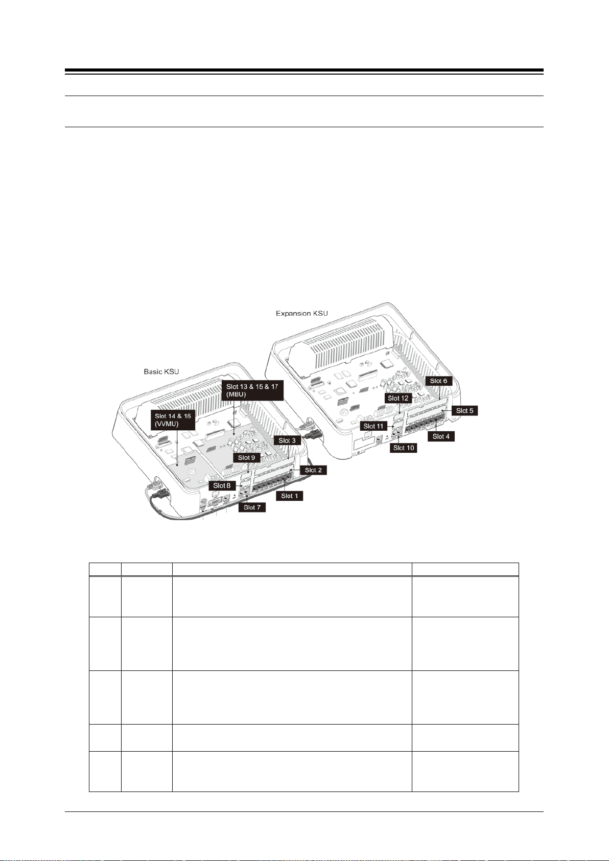
The built-in interface ports, ports of the optional Interface boards and the optional Function
boards are organized into Slots. For the built-in and optional board interfaces two Slots are
defined, a Slot for the Stations and a Slot for the CO/IP Lines. The Function boards use a single
Slot to identify the board location. The Slots are used during the initialization routines, refer to
section 2.3, to identify the installed equipment and establish the numbering for the Stations,
CO/IP lines, and Function board channels. An additional Slot (Slot 18) is used by the software
to identify the Conferencing channels as a virtual board.
The figure below depicts the Slot locations and Table 2.2-1 lists the Slots, the hardware
designation for boards applicable for the Slot and the software reference for the type of
interfaces.
Table 2.2-1 eMG80 Slot Configuration (Standard)
1 KSU
2 KSU
Built-in KSU Station interface group
KSUA and KSUI: 1-DKT & 7-Hybrid
CH204 or BH104
CH408, BH208 or HYB8
CS416 or SLIB16
HYIB8
HYIB4
HYIB8
SLIB16
3 KSU
4 EKSU
5 EKSU
CH204 or BH104
CH408, BH208 or HYB8
CS416 or SLIB16
Built-in EKSU Station interface group
CH204
CH408 or HYB8
9
HYIB4
HYIB8
SLIB16
HYIB4
HYIB8
Page 25

iPECS eMG80 & eMG800 & UCP
Slot
KSU
H/W Reference
S/W Reference
CS416 or SLIB16
SLIB16
KSUI & KSUID w/BRIU2
BRIB2
BH208
BRIB2
BH208
BRIB2
4-CO Line
LCOB4
CH409 or CS416
LCOB4
CH408 or CS416
LCOB4
13
KSU
Built-in KSU VoIP channels
VOIU
14
KSU
VVMU VoIP channels
VOIB
15
KSU
Built-in 4-port 1-Hour AA/VM
VMIU
16
KSU
VVMU 4-port, 15-hour AA/VM
VMIB
17
Miscellaneous connections
MISU
18
KSU
Virtual Slot for Conferencing channels
Administration and Programming Manual Issue 1.6
6 EKSU
7 KSU
8 KSU
9 KSU
10 EKSU
11 EKSU
12 EKSU
CH204
CH408 or HYB8
Built-in KSU Station interface group
KSUA and KSUAD: 4-CO Line
KSUI & KSUID w/PRIU:
CH204
CH408 or CS416
BH104
CH204
CH408 or CS416
BH104
Built-in EKSU Station interface group
CH204
CH204
HYIB4
HYIB8
LCOB4
PRIB
LCOB2
LCOB4
BRIB1
LCOB2
LCOB4
BRIB1
LCOB2
LCOB2
10
Page 26

iPECS eMG80 & eMG800 & UCP
Administration and Programming Manual Issue 1.6
2.3 Initialization
2.3.1 eMG Initialization
The system should be initialized before starting the configuration to assure a known starting point
and automatically register installed boards. Also, if the Nation Code requires modification, the
system will be initialized in the process so as to establish tones and gains appropriate for the
region. You can initialize the system using the Initialization switch (Dip-switch SW1, pole-2) in the
KSU or using the software Initialization PGM 450. Note the former must be used to change the
Nation Code as detailed section 3.3.1.
Basic Power-Up Routine
When the KSU power switch is turned On or the KSU Reset button is pressed with power ON, the
system will initiate the “Power-up” routine. During the Power-Up routine the system checks the
Initialization switch and, if the switch is in the Off position, the system will perform the basic
Power-up routine; clear all scratch-pad memory, load run-time programs, establish
communications with each registered Interface board, Function board, iPECS IP Phone and LDP
Phone, send Restart commands and load appropriate settings to the boards and terminals. The
KSU also will attempt to communicate and register the EKSU. If a registered board or terminal
does not respond after several attempts, the system places the device in an out-of-service mode
but maintains the configuration of the device. Once the Power-up routine is complete, the system
will conduct normal operations.
Registration of Boards
If the Initialization switch is in the ON position, in addition to the Power-Up routine, the system will
perform the full Initialization procedure. During initialization, the system attempts to communicate
with the board in each Slot, starting with Slot 1 and progressing sequentially through the slots, to
determine the installed equipment. If the board is installed, the Slot number (“Sequence Number”)
is registered, an “Order number” is determined and the MPB MAC and IP address are assigned.
Using “Order number”, which is the order that devices of the same type (CO/IP Line, Station, VSF
device, etc.) register, the system assigns the Station numbers and CO/IP Line numbers.
An exception to the above is the MAC and IP address of the VOIB which covers the VoIP
channels on the VVMU. The VOIB has a separate MAC address and the IP address is assigned
from the system. Note this IP address can be modified at a later time.
Once the system is operational and the database configured, the system can be expanded
manually by registering the optional boards as detailed in PGM 235, Registration Table.
11
Page 27

iPECS eMG80 & eMG800 & UCP
Administration and Programming Manual Issue 1.6
Initial Station and CO Numbering
The default Station Numbering Plan assigns a Three-digit number to each station port. Starting at
the first (left) port of Slot 1, the system assigns the Station Numbers beginning at “100 (eMG80)
or 1000 (eMG800)”. The Station number increments for each port in the slot, moving to the right
until reaching the last port. The process is repeated for each Station slot (1 to 6) in sequence
assigning consecutive Station Numbers.
Note the Station Number Plan can be two to four digits and the Station Number for each port can
be modified individually.
Slots 7 to 14 are then registered and, since they are CO/IP Lines, the Order numbers 1 to 8 are
used to number the CO/IP Lines. The process is repeated for each device type.
IP Phone Registration
Unregistered iPECS IP Phones attempt to discover and register with a local (on the same LAN)
iPECS system, in this case the eMG. The phone will send a registration request to the MPB IP
address. If no response is received, the phone will send a multi-cast request. With the request,
the phone will send the MAC address. This address must be assigned in the PGM 235.
When the system receives the request, the MAC address received is compared to the
Registration table and, if matched, the phone is registered, it is given the next available sequence
number starting at “19”, and assigned the next available Station Number.
If the iPECS IP Phone is configured as a remote device, it will send a registration request to the
iPECS system at the configured IP address. When the system receives the request, it is
processed normally except the MAC address must be assigned in PGM 442 Remote Device
Register.
Default Database
Based on the installed equipment, the system populates the database with the default values,
refer to Appendix C based on Keyset administration as numbering plan 1. Once the database is
set to default, the system will conduct normal operations.
12
Page 28

iPECS eMG80 & eMG800 & UCP
Administration and Programming Manual Issue 1.6
2.3.2 UCP Initialization
When power is applied to the UCP or the UCP Reset button is pressed, the system will initiate the
“Power-up” routine. During the Power-Up routine, the system will check the Initialization switch
(pole 4th of UCP Mode Dip Switch). If the switch is in the OFF position, the system will perform a
simple Power-Up routine; clear all scratch-pad memory, load run-time programs, establish
communications with each registered gateway Module and iPECS terminal, send RESTART
commands and load appropriate settings to the Modules and terminals. If a Module or terminal
does not respond after several attempts, the system places the device in an out-of-service mode
but maintains the database settings. Once the Power-up routine is complete, the system will
conduct normal operations.
If the Initialization switch is in the ON position, in place of the Power-Up routine, the system will
perform the full Initialization procedure. The initialization procedure will set the system database
to default values. Further, during the full initialization procedure, the system will establish
communications with each gateway Module and iPECS terminal for registration. This
communication will use the default device IP address and the UCP MAC address for system
identification. The system will maintain IP addresses and Sequence Numbers for previously
registered gateway Modules and iPECS terminals. These values are employed for subsequent
communication and logical assignments of numbering plans, respectively. In addition, the system
sends commands to modify all settings to the default values, including IP addresses but
maintains the existing Sequence Numbers.
After successful initialization, should a device not respond to several attempts by the system to
communicate, the system places the device in an out-of-service mode but maintains the
database. Once initialization is complete, set the initialization switch to the OFF position to protect
the database. The system must be restarted to complete the initialization.
2.3.2.1 Normal Registration Process
Module & Terminal
When power is applied and an Ethernet link is established, an unregistered device will attempt to
discover and register with a local (on the same LAN) iPECS system. The Module or terminal will
send a registration request to the assigned iPECS system (UCP) IP address. If no response is
received, the device will generate a Multi-cast discovery request for registration.
Remote iPECS Phone & Remote Services Module
A remote device, iPECS Phone or gateway Module, registers with the system using the MAC
address of the device. The MAC address must be assigned in the system database and the IP
address of the system must be assigned in the remote device. Using this address, the remote
device will attempt to register with the assigned iPECS system. When the system receives the
registration request, the MAC address is compared with the database to authenticate the remote
device. With a matching MAC, the system will accept the registration request and provide the
remote device with the appropriate settings. Note that the position of the UCP Registration switch
does not affect remote registration.
13
Page 29

iPECS eMG80 & eMG800 & UCP
Table 2.3.1 Sequence Number Allocation
Administration and Programming Manual Issue 1.6
iPECS Softphone or SIP Phone
iPECS softphones (iPECS UCS Client) and SIP phones register with the system employing the
User Id and Password. When the system receives the registration request, the Id and password
are compared to the Station Login parameters. If a match is found in the Station Login Table, the
system registers the device and assigns the phone the Station Number requested (Desired
number), if available. As with remote registration, the position of the UCP Registration switch will
not affect Softphone or SIP Phone registration.
iPECS system
When power is applied, an Ethernet link is established, and the Registration switch (UCP DIP
Switch position 3) is in the ON position, the UCP will send a Multi-cast request to unregistered
gateway Modules and iPECS terminals for registration.
When the system receives a valid registration or discovery request, and the Registration switch
(UCP DIP Switch position 3) is in the ON position, the system will respond to the gateway Module
or terminal with a Registration command including the system IP and MAC address. During the
registration process, the Module or terminal will receive data from the system including a
Sequence Number, IP address, RTP characteristics, etc., as well as default settings appropriate
to the type of Module or terminal. Once registered, the Module or terminal will maintain the
system IP and MAC address in non-volatile memory and will not attempt further registrations.
If the Registration switch is in the OFF position, the system will not respond to normal registration
requests from a local device.
Sequence Number
Sequence numbers are allocated to the different device types and are assigned sequentially to
devices of the same type as shown in the Table 2.3.1 below.
Device Type Start Sequence Number End Sequence Number
Station 1 2400
CO line 2401 3000
VSF 3001 3100
MISC 3101 3200
MCIM 3201 3230
UCS server 3231 3246
IPCR and 3rd party server 3247 3256
WTIM 3257 3388
14
Page 30

iPECS eMG80 & eMG800 & UCP
Administration and Programming Manual Issue 1.6
2.3.2.2 Replacement Module Registration
Under certain situations, it is necessary to force the registration of gateway modules and
terminals specifically when an UCP, gateway Module or iPECS Terminal is replaced. When
replacing a UCP module, gateway Modules and iPECS terminals must be forced to register with
the new system. With Module or terminal replacement, the system must recognize the
“replacement” status to transfer the existing database values.
When replacing a UCP, the local Web interface is used to access the system. The user may
update the system database using the database downloaded from the previous UCP memory.
Using the Terminal mode Command Line interface (“maint > reset ip”), the user provides the new
UCP with the IP address of the previous UCP, and issues the Register command. The new
system will then send a Uni-cast Register command to each gateway Module and iPECS terminal
registered to the previous system. This Register command will include the previous system IP
address. These commands are repeated several times only. As communication is established,
the new UCP will update the settings of the gateway Modules and iPECS terminals appropriately.
When the gateway Modules and terminals respond, they are registered to the new system.
When replacing a gateway Module, use PGM 103 “Device IP Plan” in Web admin to change the
service mode to “Out of Service”, change the MAC information for the new module, change the
service mode to in-service and install the new gateway Module.
When replacing an iPECS terminal, using PGM 103 “Device IP Plan” in Web admin change the
service mode to “Out of Service” change the MAC information for the new iPECS terminal,
change the service state to in-service, and install the new terminal.
15
Page 31

iPECS eMG80 & eMG800 & UCP
Administration and Programming Manual Issue 1.6
2.4 General Admin and Menu Structure
The iPECS system can be configured to meet each customer's individual needs. System
configuration may be accomplished by entering the “Program mode” at an assigned Admin
Station or by pointing a Web Browser at the IP address of the MPB/UCP. Section 3 provides a
description of eMG system for data entry using the Admin Station. Section 4 discusses
configuration employing the Web browser. Note that some parameters are available through Web
Admin and not the Keyset Admin.
Configurable items are organized as “Data” groups with a common affect, i.e. station, system,
numbering plan, etc. Items are further grouped into “Programs” forming a multi-layered menu
structure as the following list. Each of the Program groups is assigned a three digit “Program”
(PGM) code used to access the group. The top level Data groups include:
- System ID & Numbering Plans
- Station Data
- Board Based Data
- CO Line Data
- System Data
- Station Group Data
- ISDN Line Data
- SIP Data
- Tables Data
- Networking Data
- H.323 Routing Table
- T-NET Data
- Zone Data
- Device Login
- UCS Data
- DECT Data
- Redundancy Data (for UCP600 & UCP2400)
- Hotel Data
- Green Mode for eMG
- Initialization
The default and range of values for each configurable parameter are provided in Section Web
admin programming. The index and charts are helpful references when entering data into the
system‘s database.
16
Page 32

iPECS eMG80 & eMG800 & UCP
1
1 – 10
2
2 - 20
3
3 - 30
4
4 - 40
5
5 - 50
6
6 - 60
7
7 - 70
8
9
9 - 90
*
, - *3
0
#
Administration and Programming Manual Issue 1.6
3. STATION ADMIN PROGRAMMING
FOR E
MG
3.1 General
3.1.1 LCD & Button Functions
While in the Program mode, the Liquid Crystal Display (LCD) and Flex button LEDs of an Admin
Station are used to guide and indicate status of the feature. The dial-pad is most often used to
enter data after selecting a data item using the Flex buttons. In some cases, pressing a Flex
button will toggle the entry with the Flex button LED indicating the status (On/Off).
For Programs with multiple Flex button selections, the volume controls ([VOL UP] and [VOL
DOWN] buttons) may be used to select the next or previous item. The [SPEED] button is
generally employed as a delete button to erase existing entries. However, where noted, it may be
used to confirm a range input. Pressing the [CONF] button, returns to the 1
entry procedure for the Program without storing unsaved entries.
The [Save] button is used to store data after entry. If there are no conflicts in the entered data,
confirmation tone will be received and the data stored. If a conflict exists, error tone is provided
and newly entered data are not saved. Generally, corrected data may be entered and stored
without restarting the entry procedure from the 1
st step.
st
step of the data
3.1.2 Alphanumeric Data Entries
In some cases, an alphanumeric entry is required. Two (2) dial-pad digits represent each
character of an alphanumeric entry, as shown in Table 3.1.2–1 below. Use the Table to
determine the two digits that must be entered from the dial-pad for each character.
Table 3.1.2-1 ALPHANUMERIC DIAL-PAD ENTRIES
Q – 11
Z – 12
. – 13
G – 41
H - 42
I - 43
P - 71
R - 72
S - 73
Q - 7*
A - 21
B - 22
C - 23
J - 51
K - 52
L - 53
T - 81
U - 82
V - 83
8 - 80
D - 31
E - 32
F - 33
M - 61
N - 62
O - 63
W - 91
X - 92
Y - 93
Z - 9#
Blank - *1
: - *2
0-00
17
#
Page 33
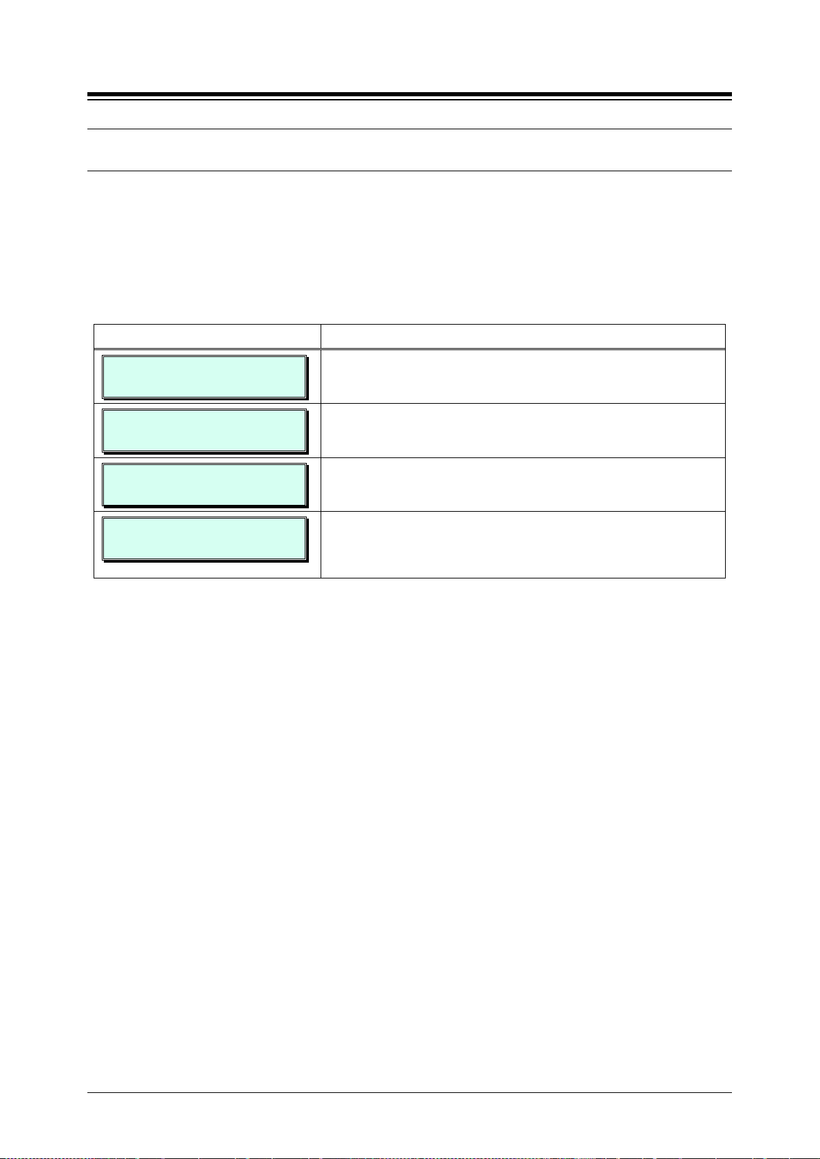
iPECS eMG80 & eMG800 & UCP
Administration and Programming Manual Issue 1.6
3.2 Data Entry Mode
Limited data entry can be accomplished from an Admin Station or station assigned for data entry
(Station Attributes III PGM 113, Flex button 1). After initialization and registration, any enabled
iPECS IP or LDP Phone may access the system database. In addition, as default, there is no
Station Admin password defined. To enter the Program mode from the Admin Station follow the
procedure below. In the left column of the chart are the LCD displays and in the right column are
step-by-step instructions to modify database items.
PROCEDURE:
STATION 100 (T)
04 SEP 01 02:49 PM
ENTER ADMIN PASSWORD
ADMIN PROGRAM START
ENTER PGM NUMBER
1. Press the [PGM] button.
Dial ‘*‘ and ‘#’.
Enter the Admin password. Confirmation tone is received. As
a default there is no password and this step is skipped.
To select a program, use the instructions in the following
sections, starting with “Press the [PGM] button” and dial the
specified Admin Program code.
18
Page 34
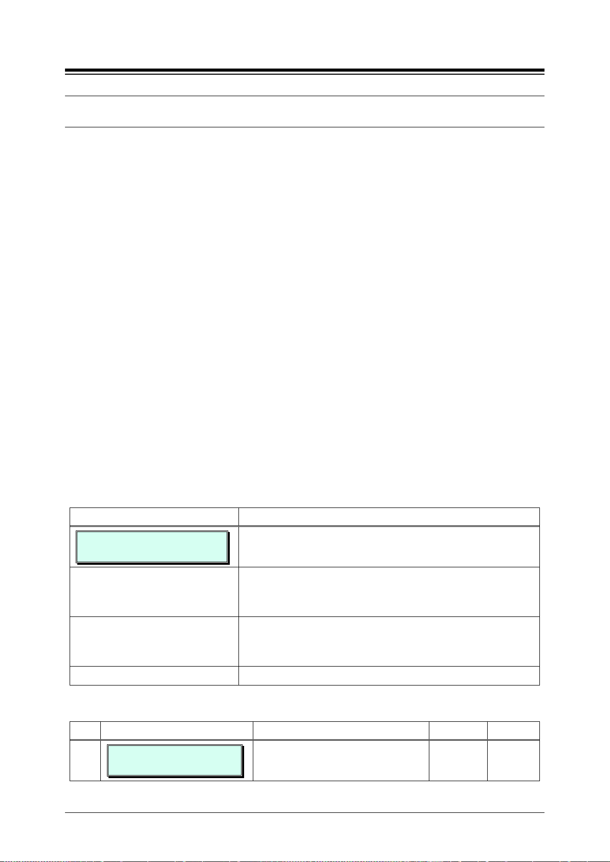
iPECS eMG80 & eMG800 & UCP
entries.
to default.
To store the System Id data press the [Save] button.
changed.
Administration and Programming Manual Issue 1.6
3.3 Procedure for Data Entry
The following sections provide specific instructions for entering data from the Admin Station once
in the Program mode. Each section provides descriptive information, step-by-step instructions
and Tables for determining appropriate entries.
3.3.1 System ID — PGM 100
Under System ID, the country is identified using the international dial codes (NATION CODE). If
the NATION code requires changing, the system must be initialized to restructure memory and
create the country specific defaults, gain, frequencies and other system characteristics specific to
the country and regional regulatory requirements.
To change the NATION Code on eMG:
Set the MPB Dip-switch 1 pole 2 to the ON position,
Follow the procedure below to modify the NATION code
Press the reset button on the KSU, power the system Off and On, or use PGM 450 to
initialize the system.
After initialization, reset switches as needed, Dip-switch 1 pole 2 should be OFF.
A twenty-four (24) character SITE NAME and the local Area Code are also defined in this
program. The SITE NAME is primarily useful for the installer/programmer as a reference to the
customer.
In addition, under this program the system can be programmed to select one of eight (8) Flexible
Number Plans, refer to Appendix B. Individual items from the selected Numbering Plan can be
changed under Flexible Numbering Plan part A to D – PGM 106 to 109- in section 3.3.2.5.
PROCEDURE:
SYSTEM ID
PRESS FLEX KEY (1-6)
1. Press the [PGM] button and dial 100.
Select the desired Flex button (1~5), refer to Table 3.3.1-1.
For COUNTRY CODE, refer to Table 3.3.1-2 for appropriate
Use the dial-pad to enter desired System Id data. For
System Reset, button 5, press [Save] to reset the System Id
Table 3.3.1-1 SYSTEM ID (PGM 100)
BTN − DISPLAY REMARK RANGE DEFAULT
1
COUNTRY CODE
1
Refer to Table 3.3.1-2 below.
Note system must be re-initialized if
19
4 digits 1
Page 35
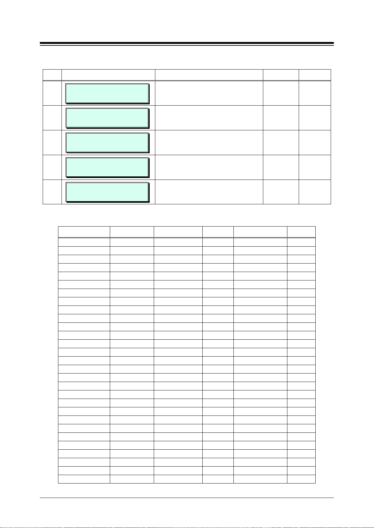
iPECS eMG80 & eMG800 & UCP
Digit Numbering Table (PGM238).
America
1
Argentina
54
Australia
61
Bahrain
973
Bangladesh
880
Belgium
32
Bolivia
591
Brazil
55
Brunei
673
Burma
95
Cameroon
237
Chile
56
China (Taiwan)
886
CIS 7 Colombia
57
Costa Rica
506
Cyprus
357
Czech
42
Denmark
45
Ecuador
593
Egypt
20
El Salvador
503
Ethiopia
251
Fiji
679
Finland
358
France
33
Gabon
241
Germany
49
Ghana
233
Greece
30
Guam
671
Guatemala
502
Guyana
592
Haiti
509
Honduras
504
Hong Kong
852
India
91
Indonesia
62
Iran
98
Iraq
964
Ireland
353
Israel
972
Italy
39
Japan
81
Jordan
962
Kenya
254
Korea
82
Kuwait
965
Liberia
231
Libya
218
Malta
356
Luxembourg
352
Malaysia
60
Morocco
212
Mexico
52
Monaco
377
Nigeria
234
Netherlands
31
New Zealand
64
Pakistan
92
Norway
47
Oman
968
Paraguay
595
Panama
507
P.N.G
675
Portugal
351
Peru
51
Philippines
63
Senegal
221
Qatar
974
Saudi Arabia
966
Spain
34
Singapore
65
South Africa
27
Sweden
46
Sri Lanka
94
Swaziland
268
Tunisia
216
Switzerland
41
Thailand
66
United Kingdom
44
Turkey
90
U.A.E.
971
Y.A.R.
967
Uruguay
598
Venezuela
58
Administration and Programming Manual Issue 1.6
Table 3.3.1-1 SYSTEM ID (PGM 100)
BTN − DISPLAY REMARK RANGE DEFAULT
2
3
4
5
6
CUSTOMER SITE NAME
………………………………….
MY MULTI AREA CODE
ENTER TABLE NO(00-40)
NUMBERING PLAN (1-9)
1
PREFIX USAGE
(1:ON/0:OFF) : OFF
SYSTEM ID
SYSTEM RESET
Refer to Table 3.1.2-1 for alphanumeric
dial-pad entries.
Enter the area code of the installed site. 6 digits
Refer to Appendix B for details of
Numbering Plan selection.
Enable/Disable 8-digit Station Numbering
Plan. Assign the Prefix codes in the 8-
Returns the System Id to default.
24
character
1-9 1
0: OFF
1: ON
OFF
Table 3.3.1-2 COUNTRY CODES
COUNTRY CODE COUNTRY CODE COUNTRY CODE
20
Page 36
iPECS eMG80 & eMG800 & UCP
Select the desired button 1~19, refer to Table 3.3.2.1-1.
Press the [Save] button to store IP address entries.
Table 3.3.2.1-1 SYSTEM IP ADDRESS PLAN (PGM 102)
external VoIP network access. IPv4 format.
Administration and Programming Manual Issue 1.6
3.3.2 NUMBERING PLANS DATA — PGM 102 to 109
3.3.2.1 System IP Address Plan — PGM 102
The System IP Address Plan sets several IP addresses including the KSU LAN port IP address
(MPB IP Address) required for external VoIP calls, the IP address for the router, and the system‘s
internal private IP address Plan. Note that the MPB and Router addresses and sub-net mask
must be a routable IP address for access to an external VoIP network, remote access by a
gateway/board or terminal and remote Web access. The VOIB must also have a routable IP
address for access to/from an external VoIP network or remote user.
When Automatic IP Assignment, button 7, is enabled, the system will assign IP addresses to
each local terminal and the VOIB using the assigned System IP address range. These addresses
are used for communications between the system and the VOIB and terminals.
The system may be connected to a LAN that is segmented by two separate private IP address
schemes. This segmenting technique is often used to separate voice and data devices.
However, with this segmenting technique, the system would normally treat the segmented
Terminals such as iPECS Soft Phones, as remote devices, using valuable WAN bandwidth.
Assigning the “Second Sys IP address” with valid IP address from the second segment permits
the system to communicate with the devices directly over the LAN.
iPECS can be installed behind a NAPT server, if the NAPT server provides fixed address
translation and port forwarding to the system. In this case, the system will employ the “Firewall IP
address”, button 10, as the fixed public IP address for communication with remote devices. This
address must be assigned as the “MPB” address in the remote device.
PROCEDURE:
SYSTEM IP ADDRESS PLAN
PRESS FLEX KEY (01-17)
1. Press the [PGM] button and dial 102.
Use the dial-pad to enter desired IP addresses. Use an “*” to
enter a dot (“.”)
BTN DISPLAY DEFAULT REMARK
1
MPB IP ADDRESS
10 . 10 . 10 . 2
2
MPB SUB NET MASK
255.255.255.0
3
ROUTER IP ADDRESS
10 . 10 . 10 . 1
4
SYSTEM START IP ADDRESS
10.10.10.10
10.10.10.2 This is the IP address of the KSU LAN port A. A
Public IP Address is required for remote user and
255.255.0.0
10.10.10.1 IP Address of router for external network (WAN)
access. Required for shared voice and data LAN,
external VoIP and remote Web access.
10.10.10.10 Start of range for private IP addresses assigned by
the system to Modules/Terminals.
21
Page 37
iPECS eMG80 & eMG800 & UCP
Table 3.3.2.1-1 SYSTEM IP ADDRESS PLAN (PGM 102)
address for the second LAN.
remote devices.
from iPECS.
Administration and Programming Manual Issue 1.6
BTN DISPLAY DEFAULT REMARK
5
6
7
8
9
10
11
12
13
14
15
SYSTEM END IP ADDRESS
10.10.10.254
SYSTEM SUB NET MASK
255.255.255.0
AUTOMATIC IP ASSIGN
(1:ON/0:OFF): ON
SECOND SYS IP ADDRESS
0 . 0 . 0 .0
SECOND SYS SUB NET MASK
255.255.255 .0
FIREWALL IP ADDRESS
0 . 0 . 0 .0
FIRST START MAC ADDR
000000000000
FIRST END MAC ADDR
000000000000
SECOND START MAC ADDR
000000000000
SECOND END MAC ADDR
000000000000
SYSTEM IP ADDRESS PLAN
SYSTEM RESET
10.10.10.254 End of range for private IP addresses assigned by
the system to Modules/Terminals.
255.255.0.0
ON The system will automatically assign IP addresses
to modules and terminals (ON) or, when OFF, IP
addresses are assigned manually in PGM 103
Device IP Address Plan.
0.0.0.0 When devices are located on a different private
address on the same net, enter the MPB IP
255.255.255.0
0.0.0.0 When the system is installed behind a NAPT
server, the fixed IP Address provided by the NAPT
server must be assigned in this field.
Also, use this IP address for the MPB address in
00.00.00.0
0.00.00
00.00.00.0
0.00.00
00.00.00.0
0.00.00
00.00.00.0
0.00.00
Returns System IP Address Plan to default values.
A range of MAC addresses can be entered to
register devices. This entry is the start address of
the first range.
A range of MAC addresses can be entered to
register devices. This entry is the end address of
the first range.
A range of MAC addresses can be entered to
register devices. This entry is the start address of
the second range.
A range of MAC addresses can be entered to
register devices. This entry is the end address of
the second range.
16
17
MPB DNS IP ADDR
0 . 0 . 0 .0
MPB DHCP
(1:ON/0:OFF) : OFF
0.0.0.0 IP Address of Domain Name Server, which iPECS
will use to resolve URL to an IP address. The DNS
provides the resolution after receiving the name
OFF Enable/Disable DHCP client function for the MPB.
22
Page 38
iPECS eMG80 & eMG800 & UCP
Button 7: WTIB
Administration and Programming Manual Issue 1.6
3.3.2.2 Device IP Address Plan -PGM 103
TDM board is registered with own slot number. It is registered automatically without any
configuration.
To register an IP device:
As IP gateway/board and terminals register to the iPECS, a logical slot number is assigned,
which indicates the order of registration. Also, based on the type of device (CO/IP gateway/board,
Terminal) the system assigns a logical Sequence Number. Thus, Sequence Numbers for CO
gateway/board, Terminals are independently assigned based on the type of gateway/board.
These Sequence Numbers are employed to provide a relationship between the physical MAC
address and the logical port numbers of the device.
The system may assign a default private IP address to each Sequence Number. If desired, this
program may be used to modify the assigned IP address for each gateway/board and iPECS
Phone.
Each local gateway/board and terminal can be assigned for “Direct Send”. With Direct Send
enabled, the system will employ the Ethernet MAC address, layer 2 switching to eliminate the
need for IP traffic overhead, reducing overall LAN traffic.
The system normally employs IP multi-cast protocol to respond to a registration request from a
gateway/board or terminal. When the device is separated from the system by a router, the system
must use the IP uni-cast protocol. This is established by the “Local Device” assignment.
When disabled (Off), the system will send an IP uni-cast message to the device in response to a
registration request.
PROCEDURE:
DEVICE IP ADDRESS PLAN
PRESS FLEX KEY (1-7)
1. Press the [PGM] button and dial 103.
Select the desired Flex button.
Button 1: CO & VOIP Gateway/Board
Button 2: Stations
Button 3: MISU
Button 4: VMIU, VMIB
Button 5: MCIB
Button 6: SYSTEM RESET
Use the [VOL UP] and [VOL DOWN] buttons to see next/
previous IP Address. Refer to Table 3.3.2.2-1 for display
information.
23
Page 39
iPECS eMG80 & eMG800 & UCP
Button 6: Device (Board) ID
Press the [Save] button to store the data entry.
in PGM 102.
common LAN with the MPB.
Number, 2~4 digits IP Address, 7~12 digits
in PGM 102.
Administration and Programming Manual Issue 1.6
PROCEDURE:
Press Flex 1~6 to select the Sub-menu item desired. See
Table 3.3.2.2-1.
Button 1: IP address
Button 2: MAC address
Button 3: ARP
Button 4: REGISTRATION
Button 5: CPU Type
Use the dial-pad to enter desired data. For IP and MAC
addresses, an “*” is used to enter a dot (“.”)
Table 3.3.2.2-1 DEVICE & STATION ADDRESS PLAN (PGM 103)
BTN DISPLAY FEATURE DEFAULT
1
1–1
1–2
1–3
1–4
1–5
001-001 :B40EDCBF5606
VOIP 1 :10 .10 .10 .2
SET IP ADDRESS
VOIP 1 : 10.10.10.2
SET MAC ADDRESS
001-001 : B40EDCBF5606
ARP
(1:ON/0:OFF): OFF
REGISTRATION
(0:UCAST/1:MCAST): MCAST
CPU TYPE
MSC1K
LCD shows:
Line 1 Sequence Number, 2 or 3 digits MAC
Address, 12 digits
Line 2 Module Type, 4 characters First Logical
port number IP Address, 7~12 digits
Use Flex button 1 to set the device‘s IP address
in IP v4 format.
Use Flex button 2 to enter the device‘s MAC
address in the system memory.
Use Flex button 3 to enable/disable Direct Send
mode, which employs layer 2 switching to local
devices.
Use Flex button 4 to enable/disable Local
Device Mode, which defines the device as on a
Flex button 5 displays the type of CPU
employed in the device.
CO & VoIP
board IP
address set
sequentially,
from the range
10.10.10.10~254
None
OFF
MCAST
1–6
2
2–1
DEVICE(BOARD) ID
PRIB
001-001 : B40EDCBF5606
KTU 100 :10.10.10.10
SET IP ADDRESS
KTU 100 :10.10.10.10
Flex button 6 displays the Board type
designation.
LCD shows:
Line 1 Sequence Number, 3 digits MAC
Address, 12 digits
Line 2 Station Type, 3 characters Station
Use Flex button 1 to set the device‘s IP address
in IP v4 format.
24
Station IP
address set
sequentially,
from the range
10.10.10.10~254
Page 40
iPECS eMG80 & eMG800 & UCP
devices.
common LAN with the MPB.
automatically,
devices.
Administration and Programming Manual Issue 1.6
Table 3.3.2.2-1 DEVICE & STATION ADDRESS PLAN (PGM 103)
BTN DISPLAY FEATURE DEFAULT
2–2
2–3
2–4
2–5
2–6
3
3–1
SET MAC ADDRESS
001-001 : B40EDCBF5606
ARP
(1:ON/0:OFF): OFF
REGISTRATION
(0:UCAST/1:MCAST): MCAST
CPU TYPE
MSC1K
DEVICE(BOARD) ID
HYIB
001-017 : B40EDCBF5606
MISU :10.10.10.2
SET IP ADDRESS
MISU :10.10.10.2
Use Flex 2 button to enter the device‘s MAC
address into system memory.
Use Flex button 3 to enable/disable Direct Send
mode, which employs layer 2 switching to local
Use Flex button 4 to enable/disable Local
Device Mode, which defines the device as on a
Flex button 5 displays the type of CPU
employed in the device.
Flex button 6 displays the terminal type
designation.
LCD shows:
Line 1 Sequence Number, 2 digits MAC
Address, 12 digits Line 2 “MISU” IP Address,
7~12 digits.
Use Flex button 1 to set the device‘s IP address
in IP v4 format.
None
OFF
MCAST
IP address of
MISU.
Functions in the
system‘s MPB
set
10.10.10.10~254
3–2
3–3
3–4
3–5
3–6
4
4–1
SET MAC ADDRESS
001-003 : B40EDCBF5606
ARP
(1:ON/0:OFF): OFF
REGISTRATION
(0:UCAST/1:MCAST): MCAST
CPU TYPE
MSC1K
DEVICE(BOARD) ID
MISU
001-015 : B40EDCBF5606
VMIU :10.10.10.2
SET IP ADDRESS
VMIU :10.10.10.2
Use Flex button 2 to enter the device‘s MAC
address into system memory.
Use Flex button 3 to enable/disable Direct Send
mode, which employs layer 2 switching to local
Use Flex button 4 to enable/disable Local
Device Mode, which defines the device as on a
common LAN with the MPB.
Flex button 5 displays the type of CPU
employed in the device.
Flex button 6 displays the MISU type
designation.
LCD shows:
Line 1 Sequence Number, 2 digits MAC
Address, 12 digits Line 2 device type and IP
address.
Use Flex button 1 to set the device‘s IP address
in IP v4 format.
None
OFF
MCAST
.
10.10.10.10~254
25
Page 41
iPECS eMG80 & eMG800 & UCP
common LAN with the MPB.
address.
devices.
common LAN with the MPB.
Address, 7~12 digits.
Administration and Programming Manual Issue 1.6
Table 3.3.2.2-1 DEVICE & STATION ADDRESS PLAN (PGM 103)
BTN DISPLAY FEATURE DEFAULT
4–2
4–3
4–4
4–5
4–6
5
5–1
SET MAC ADDRESS
001-015 : B40EDCBF5606
ARP
(1:ON/0:OFF): OFF
REGISTRATION
(0:UCAST/1:MCAST): MCAST
CPU TYPE
MSC1K
DEVICE(BOARD) ID
VMIU
001-018 : FFFF0000FFFF
MCIB : 10 .10 .10 .2
SET IP ADDRESS
MCIB :10.10.10.2
Use Flex button 2 to enter the device‘s MAC
address into system memory.
Use Flex button 3 to enable/disable Direct Send
mode, which employs layer 2 switching to local
devices.
Use Flex button 4 to enable/disable Local
Device Mode, which defines the device as on a
Flex button 5 displays the type of CPU
employed in the device.
Flex button 6 displays the type designation.
LCD shows:
Line 1 Sequence Number, 2 digits MAC
Address, 12 digits Line 2 device type and IP
Use Flex button 1 to set the device‘s IP address
in IP v4 format.
None
OFF
MCAST
10.10.10.10~254
5–2
5–3
5–4
5–5
5–6
6
7
SET MAC ADDRESS
001-018 : FFFF0000FFFF
ARP
(1:ON/0:OFF): OFF
REGISTRATION
(0:UCAST/1:MCAST): MCAST
CPU TYPE
MS828
DEVICE(BOARD) ID
MCIB_V
DEVICE IP ADDRESS PLAN
SYSTEM RESET
001-003 : 00405A142C67
WTIB : 10:10:10:14
Use Flex button 2 to enter the device‘s MAC
address into system memory.
Use Flex button 3 to enable/disable Direct Send
mode, which employs layer 2 switching to local
Use Flex button 4 to enable/disable Local
Device Mode, which defines the device as on a
Flex button 5 displays the type of CPU
employed in the device.
Flex button 6 displays the type designation,
MCIB_V.
If the [Save] button is pressed, the system will
reset and restart.
LCD shows:
Line 1 Sequence Number, 2 digits MAC
Address, 12 digits Line 2 “WTI4” and IP
None
OFF
MCAST
7–1
SET IP ADDRESS
WTIB :10.10.10.14
Use Flex button 1 to set the device‘s IP address
in IP v4 format.
26
10.10.10.10~254
Page 42
iPECS eMG80 & eMG800 & UCP
2 switching to local devices.
Local Device Mode.
the next/previous set of six Sequence Numbers.
number associated with the selected Sequence Number.
[Save]
Administration and Programming Manual Issue 1.6
Table 3.3.2.2-1 DEVICE & STATION ADDRESS PLAN (PGM 103)
BTN DISPLAY FEATURE DEFAULT
7–2
7–3
7–4
7–5
7–6
SET MAC ADDRESS
001-003 : 00405A142C67
ARP
(0:ON/1:OFF): OFF
REGISTRATION
(0:UCAST/1:MCAST):MCAST
CPU TYPE
MS828
DEVICE(BOARD) ID
WTIB
Use Flex button 2 to enter the device‘s MAC
address into system memory.
Use Flex button 3 to enable/disable ARP, ARP
OFF enables Direct Send, which employs layer
Use Flex button 4 to disable/enable Local
Device Mode, which defines the device as on a
common LAN with the system. MCAST enables
Flex button 5 displays the type of CPU
employed in the device.
Flex button 6 displays the type designation,
WTIB.
3.3.2.3 CO Device Sequence Number -PGM 104
The system uses the Sequence Number to assign logical (software) port numbers. This
Sequence Number relates the hardware and software port numbers for each device.
None
OFF
MCAST
PROCEDURE:
001 002 003 004 005 006
009 007 008 013 014 . . .
001 002 003 004 005 006
009 007 008 013 014 . . .
001 002 003 004 005 006
009 007 008 013 014 . . .
1. Press the [PGM] button and dial 104.
Press the Flex button (1~6) for the desired Sequence
Number, use the [VOL UP] and [VOL DOWN] buttons for
Using the dial pad, enter new slot numbers. Note slot
numbers cannot be duplicated and duplicates will cause an
error. The [SPEED] button may be used to erase the slot
Press the
button to store the new Slot data.
27
Page 43
iPECS eMG80 & eMG800 & UCP
the next/previous 2 station Sequence Numbers.
4.2 Dial new station number.
[Save]
Administration and Programming Manual Issue 1.6
3.3.2.4 Flexible Station Numbering Plan -PGM 105
Each LDP Phone, iPECS IP Phone and SLT is assigned a Sequence Number during the
registration process. The station Sequence Number is a 3-digit number starting at 001, which is
incremented as each terminal device is registered. At registration, station numbers increment
sequentially with the Sequence Number and are assigned starting at station 100 for Sequence
Number 001. The Station Numbering Plan allows the station numbers to be Three (3) to eight (8)
digits in length.
PROCEDURE:
001 002 003 004
100 101 102 103
001 002 003 004
… … … …
1. Press the [PGM] button and dial 105.
Use either of the two methods below to change the station
number associated with a Sequence Number. Note pressing
the [SPEED] button twice clears all station number
assignments.
The [VOL UP] / [VOL DOWN] buttons are used to view
Range entry:
Using the dial-pad, enter a station number range (first &
last station number). The two station numbers must be of
the same length, 2~8 digits. The range assignment
begins with the first station number shown by the LCD
and continues to the end of the entered range.
Single entry:
4.1 Press Flex button 1~4 to select the desired Sequence
Number from the two shown by the LCD.
Press the
button to store the new station numbers.
28
Page 44
iPECS eMG80 & eMG800 & UCP
109 for part D.
PGM
required, input the first and last numbers in the range.
Administration and Programming Manual Issue 1.6
3.3.2.5 Flexible Numbering Plan part A to D - PGM 106 to 109
Feature dial codes for the system can be assigned using the system‘s Flexible Numbering Plan.
Feature codes should be one (1) to four (4) digits in length and must not conflict. For example,
Feature dial codes 53 and 536 represent a conflict. The system will generate error tone and will
not update the database. Table 3.3.2.5-1 to Table 3.3.2.5-4 below show the defaults for the 1st
base Numbering Plan. Appendix B provides the default values for each of the 9 basic Numbering
Plans, select the base Numbering Plan in PGM 100. The default is based on Numbering plan 1.
PROCEDURE:
FLEX NUMBERING PLAN A
PRESS FLEX KEY (01-24)
1. Press the [PGM] button and dial:
106 for part A
107 for part B
108 for part C
Select the desired button (01~24); refer to Table 3.3.2.5-1 to
Table 3.3.2.5-4 for
106 to 109 respectively.
Use the dial-pad to enter desired data. Where a range is
Press the [Save] button to store the new Numbering Plan
data.
Table 3.3.2.5-1 FLEXIBLE NUMBERING PLAN PART A (PGM 106)
BTN DISPLAY FEATURE DEFAULT
1
2
INT PAGE ZONES
START& END:301-335
INT ALL CALL
ENTER NEW #:543
Internal Page Zone access codes. eMG80:301~335
eMG800:301~400
Internal All Call Page access code. 543
3
4
5
6
7
MEET ME PAGE
ENTER NEW #:544
EXT PAGE ZONE 1
ENTER NEW #:545
UNUSED
EXT ALL CALL
ENTER NEW #:548
ALL CALL PAGE
ENTER NEW #:549
Meet-Me-Page answer code. 544
External Page Zone 1 access code. 545
External All Call Page access code. 548
All Call Page access code. 549
29
Page 45
iPECS eMG80 & eMG800 & UCP
Administration and Programming Manual Issue 1.6
Table 3.3.2.5-1 FLEXIBLE NUMBERING PLAN PART A (PGM 106)
BTN DISPLAY FEATURE DEFAULT
8
9
10
11
12
13
14
15
SMDR ACT CODE ENTER
ENTER NEW #:550
FLASH CMD TO CO
ENTER NEW #:551
SLT LAST SPD DIAL
ENTER NEW #:552
DND
ENTER NEW #:553
CALL FWD
ENTER NEW #:554
SPD DIAL PGM
ENTER NEW #:555
MSG WAIT ENABLE
ENTER NEW #:556
MSG WAIT RETURN
ENTER NEW #:557
Dial code to signify the start of an SMDR
Account Code.
Dial code to generate a Flash on the
active CO Line.
SLT Last Number Redial feature access
code.
Dial code to activate Do-Not-Disturb. 553
Dial code to activate Call Forward. 554
Speed Dial programming access dial
code for SLTs.
Dial code to activate a Message
Wait/Call Back.
Dial code to return a Message Wait/Call
Back.
550
551
552
555
556
557
16
17
18
19
20
21
22
23
SPD DIAL ACCESS
ENTER NEW #:558
DND/FWD CANCEL
ENTER NEW #:559
CO SYS HOLD
ENTER NEW #:560
SLT PGM MODE ENTER
ENTER NEW #:561
ATTD UNAVAILABLE
ENTER NEW #:562
ALARM RESET
ENTER NEW #:565
GROUP CALL PICK-UP
ENTER NEW #:566
UNIVERSAL ANSWER
ENTER NEW #:567
SLT Speed Dial access code. 558
Dial code to cancel DND/FWD/MSG
Wait.
Dial code to place a CO call on System
Hold.
User program mode entry dial code for
SLTs.
Dial code to place attendant in the
“unavailable” mode, attendant only.
Dial code to terminate Alarm contact
signal.
Group Call Pick-up dial code. 566
Universal Night Answer dial code. 567
559
560
561
562
565
30
Page 46
iPECS eMG80 & eMG800 & UCP
code.
Administration and Programming Manual Issue 1.6
Table 3.3.2.5-1 FLEXIBLE NUMBERING PLAN PART A (PGM 106)
BTN DISPLAY FEATURE DEFAULT
24
ACCNT CODE WITH BIN
ENTER NEW #:568
Dial code for entering an Account code. 568
Table 3.3.2.5-2 FLEXIBLE NUMBERING PLAN PART B (PGM 107)
BTN DISPLAY FEATURE DEFAULT
1
2
3
4
5
WALKING COS
ENTER NEW #:569
ACD AGENT ON/OFF DUTY
ENTER NEW #:571
ACD SUPERVISOR LOGIN
ENTER NEW #:572
ACD SUPERVISOR LOGOUT
ENTER NEW #:573
ACD HELP CODE
ENTER NEW #:574
Dial code to activate Walking Class-ofService.
Dial code to toggle ACD Agent or
Supervisor ON and OFF duty.
Supervisor login dial code. 572
Supervisor logout dial code. 573
Agent code requesting Supervisor help
and Supervisor Help request Response
569
571
574
6
7
8
9
10
11
12
13
ACD CALLS IN QUEUE
ENTER NEW #:575
ACD SUPERVISOR STATUS
ENTER NEW #:576
ACD SUPERVISOR MONITOR
ENTER NEW #:577
ACD REROUTE QCALL ANS
ENTER NEW #:578
ACD REROUTE QCALL NO AN
ENTER NEW #:579
CAMP-ON ANSWER
ENTER NEW #:621
CALL PARK LOCATIONS
START#:#601-#619
STA GRP PILOT NUMBER
START #:401-440
Dial code to display calls in queue. 575
Dial code to display group status. 576
Dial code to activate Supervisor monitor. 577
Dial code to reroute call after answer. 578
Dial code to reroute call prior to answer. 579
Dial code to answer a Camped On call. 621
Dial code to place/retrieve a call in a
Park location.
Station group pilot numbers. eMG80:401~440
eMG80:#601~#619
eMG800:#601~#800
eMG800:401~500
31
Page 47
iPECS eMG80 & eMG800 & UCP
Administration and Programming Manual Issue 1.6
Table 3.3.2.5-2 FLEXIBLE NUMBERING PLAN PART B (PGM 107)
BTN DISPLAY FEATURE DEFAULT
14
15
16
17
18
19
20
21
STA USER VSF FEATURES
ENTER NEW #:*66
CALL COVERAGE RING
ENTER NEW #:76
DIRECT CALL PICK-UP
ENTER NEW #:*77
ACCESS CO GROUP FEAT
ENTER NEW #:89
ACCESS IND CO/IP FEAT
ENTER NEW #:88
ACCESS HELD CO/IP FEAT
ENTER NEW #:8*
ACCESS HELD IND CO/IP
ENTER NEW #:8#
ACCESS CO IN 1ST CO GRP
ENTER NEW #:9
VSF feature access code. *66
Code for Call Coverage button. 76
Dial code to activate Directed Call Pickup.
Dial code to access a CO Line or IP
channel from a CO/IP group.
Dial code to access a specific CO Line. 88
Dial code to access last held CO Line or
IP channel from Hold.
Dial code to access a specific CO Line/IP
channel from Hold.
Dial code to access the 1st available CO
Line in any accessible group.
*77
89
8*
8#
9
22
23
24
ATTENDANT CALL
ENTER NEW #:0
VM MSG WAIT ENABLE
ENTER NEW #:*8
VM MSG WAIT CANCEL
ENTER NEW #:*9
Dial code to call an Attendant. 0
Dial code for external Voice mail to
activate Message Wait indication.
Dial code for external Voice Mail to
deactivate Message Wait indications.
*8
*9
Table 3.3.2.5-3 FLEXIBLE NUMBERING PLAN PART C (PGM 108)
BTN DISPLAY FEATURE DEFAULT
1
2
DOOR OPEN 1
ENTER NEW #:#*1
DOOR OPEN 2
ENTER NEW #:#*2
Dial code to activate Door 1 contact
(open door 1)
Dial code to activate Door 2 contact
(open door 2).
#*1
#*2
32
Page 48
iPECS eMG80 & eMG800 & UCP
Not available in USA version.
button for proper operation.
using this code.
Administration and Programming Manual Issue 1.6
Table 3.3.2.5-4 FLEXIBLE NUMBERING PLAN PART D (PGM 109)
BTN DISPLAY FEATURE DEFAULT
1
2
3
4
5
6
7
8
MCID REQUEST
ENTER NEW #:*0
AME FEATURE
ENTER NEW #: 564
US-CONF TMR EXTENSION
ENTER NEW #:##
PTT GROUP LOGIN/OUT
ENTER NEW #:#0
ACD AGENT P LOGIN
ENTER NEW #:581
ACD AGENT P LOGOUT
ENTER NEW #:582
ACD AGENT S LOGIN
ENTER NEW #:583
ACD AGENT S LOGOUT
ENTER NEW #:584
Dial code to activate Malicious Call ID
Request in ISDN Supplementary service.
Dial code to assign an Answering
Machine Emulation Flex button.
Dial code to extend Unsupervised
conference time.
Push-To-Talk group login and logout dial
code. The station must have a PTT
ACD Agent Primary Login code. 581
ACD Agent Primary Logout code. 582
ACD Agent Secondary Login code. 583
ACD Agent Secondary Logout code. 584
*0
564
##
#0
9
10
11
12
13
14
15
16
ACD AGENT WRAPUP END
ENTER NEW #:585
TNET CM LOGIN/OUT
ENTER NEW #:586
ENTER INTO CONF-ROOM
ENTER NEW #:59
ENTER INTO CONF-GROUP
ENTER NEW #:68
STATION ICR
ENTER NEW #:587
PICK UP GROUP PICK-UP
ENTER NEW #:588
EMERGENCY PAGE
ENTER NEW #:589
REMOTE MEX CONTROL
ENTER NEW #:580
ACD Agent wrap-up end code. 585
When Central Control networking (TNET)
is employed, a station can be manually
logged in or out of the Central system
Code for a station to enter a conference
room.
Code to open a conference group. 68
Code to activate Station ICR. 587
Pick Up Group Call Pick-up dials code. 588
Code for emergency page. 589
Code to control the mobile extension
settings remotely.
586
59
580
33
Page 49
iPECS eMG80 & eMG800 & UCP
Directory feature. (USA Only)
and system starts DISA service.
Administration and Programming Manual Issue 1.6
Table 3.3.2.5-4 FLEXIBLE NUMBERING PLAN PART D (PGM 109)
BTN DISPLAY FEATURE DEFAULT
17
18
19
20
21
22
23
24
ALL GR AGENT ON/OFF DUT
ENTER NEW #:58*
SLT ACNR CODE
ENTER NEW #:58#
ACD SUPERVISOR RING MODE
ENTER NEW #:570
COMPANY DIRECTORY NAME
ENTER NEW #:563
ISDN SUPP HOLD
ENTER NEW #:57*
ISDN SUPP CONF
ENTER NEW #:57#
FORCED SEIZE BUSY STN/CO
ENTER NEW #:56*
ADDED FLEX NUMBER PLAN
PRESS FLEX KEY (1-5)
Code to change the state of the Agent
ON/Off duty in all hunt groups.
In SLT, user can ACNR feature by using
this numbering plan.
Code to check and change ACD group
Ring mode by ACD group supervisor.
Code to check and change recording
station subscribe name of Company
ISDN Supplementary Service for HOLD. 57*
ISND Supplementary Service for
Conference (Not supported).
Busy Station / CO can be connected with
entering this Code.
58*
58#
570
563
57#
56*
24-1
24-2
24-3
24-4
24-5
OVERRIDE DND/CFW
ENTER NEW #:56#
CANCEL CALL BACK
ENTER NEW #:….
XFER TO VSF ANNC NO
ENTER NEW #:55*
CCR
ENTER NEW #:#2
UCS SYS CONF GRP JOIN
ENTER NEW #:5*0
[56#] + Station number, then the station’s
DND or CFW setting will be overridden.
It is used to cancel call back.
When a station is talking over a CO line
User, [Transfer] + [55*] + Valid system
announcement (01-70), then Outside
user can hear system announcement,
It is used in digit conversion. #2
It is used to join UCS conference group
by entering the code.
56#
55*
5*0
34
Page 50
iPECS eMG80 & eMG800 & UCP
Use the dial-pad to enter the required data.
[Save]
assign method. (ex : 4+0 → 4)
Administration and Programming Manual Issue 1.6
3.3.2.6 8-Digit Table
We can support it more 4 digits for station number. Station numbering should not conflict with
numbering plan. It is consist of prefix digits and add digits. Prefix digits can have up to 4 digits
and Add digits can have up to 4 digits.
PROCEDURE:
DIGIT 8 TBL
ENTER TBL NO(01-10)
Digit 8 TBL 1 : Empty
1. Press the [PGM] button and dial 238.
Use the dial-pad to enter the desired table number.
Press the desired Flex button; refer to Table 3.3.2.6-1.
Press the
button to store the data entry.
Table 3.3.2.6-1 8-Digit Table (PGM 238)
BTN ATTRIBUTE/DISPLAY DESCRIPTION RANGE DEFAULT
1
2
TBL 1 : SET 8 digit
8 Digit 1 : …....
TBL 1: SET ADD DIGIT
ADD DIGIT : 0
The user may be allowed to enter
the prefix digits using character
The user can be allowed to add
digits. (ex: if it’s set 3, prefix digits +
xxx)
Up to 4 digits N/A
Up to 4 digits 0
35
Page 51
iPECS eMG80 & eMG800 & UCP
procedure for an iPECS DSS Console.
refer to Table 3.3.3.1–1.
Press the [Save] button to store the data entries.
IP KEYSET
DSS MAP 1
DSS MAP 2
DSS MAP 3
SLT (DTMF)
SLT (DTMF) – Voltage Message lamp
SLT (DTMF) – FSK Message lamp
SLT (DTMF) – Polarity Reversal Message lamp
Administration and Programming Manual Issue 1.6
3.3.3 Station Data –PGM 110-125
3.3.3.1 Station Type -PGM 110
Each station is assigned a type, which is used by the system to recognize the station‘s
capabilities and default Flex button configuration. In addition, for the iPECS DSS/BLF Consoles,
the associated station number is identified here. Note that the maximum of three (3) DSS
Consoles(LIP DSS & LDP DSS) can be associated and connected to a station.
PROCEDURE:
STATION TYPE ASSIGN
ENTER STA RANGE
100-110 F1:TY F2:ASC
IPKTU
1. Press the [PGM] button and dial 110.
Use the dial-pad to enter a station range (Ex 100~110). For
a single station, enter the same number twice; use this
Select Flex button 1, to set the station type and, for iPECS
DSS Consoles (types 2~4), Flex button 2 assigns the
associated station.
100-110 F1:TY F2:ASC
IPKTU
111-111 F1:TYPE F2 :ASC
DSS MAP2 : STA . . . .
Use the dial-pad to enter desired data:
4-1. For Flex button 1 (TYPE), enter the station TYPE;
4-2. For Flex button 2 (Associated station), enter the
number of the station used with the console. Flex button
2 is only available for iPECS DSS Consoles (Types 2~4),
see Table 3.3.3.1-2 for default configurations.
Table 3.3.3.1-1 STATION TYPE ASSIGNMENT — (PGM 110)
TYPE DESCRIPTION
1
2
3
4
5
6
7
8
36
Page 52
iPECS eMG80 & eMG800 & UCP
Table 3.3.3.1-2 CONSOLE BUTTON CONFIGURATION (PGM 110 )
Button 1: Intrusion
Button 2: All Call Page
Button 3: Call Park 1
Button 4: Station Group 1
Button 5: Camp-On
Button 6: Internal All Call Page
Button 7: Call Park 2
Button 8: Station Group 2
Button 9: [Release]
Button 10: Ext. All Call Page
Button 11: Call Park 3
Button 12: Station Group 3
Buttons 13 ~ 48: Station Ports 100 ~ 135
MAP 2
Station Ports 136 ~ 183
MAP 3
Station Ports 184 ~ 231
113 for Station Attributes III
Table 3.3.3.2-3.
Press the [Save] button to store the data entry.
is pressed, no need to lift handset.
Administration and Programming Manual Issue 1.6
MAP DEFAULT CONSOLE BUTTON CO NFIGURATION
MAP 1
3.3.3.2 Station Attributes I to III - PGM 111-113
Station Attributes define features and functions available to the station. Generally, the entry will
turn the feature ON (enable) or OFF (disable). Refer to Table 3.3.3.2-1 to Table 3.3.3.2-3 for a
description of the features and the input required.
PROCEDURE:
STATION ATT 1
ENTER STA RANGE
1. Press the [PGM] button and dial:
111 for Station Attributes I
112 for Station Attributes II
100-110 STAT I O N ATT 1
PRESS FLEX_KEY (01-24)
Use the dial-pad to enter a station range (Ex. 100~110). For
a single station, enter the same number twice.
Press the desired Flex button; refer to Table 3.3.3.2-1 to
Use the dial-pad to enter desired data for the attribute
setting, refer to Table 3.3.3.2-1 to Table 3.3.3.2-3.
Table 3.3.3.2-1 STATION ATTRIBUTES I (PGM 111)
BTN ATTRIBUTE/DISPLAY DESCRIPTION RANGE DEFAULT
1
100-110 AUTO SPKR
(1:ON/0:OFF) : ON
Enables [SPEAKER] activation when
a CO/IP, DSS or other feature button
0: OFF
1: ON
ON
2
100-110 CALL FWD
(1:ON/0:OFF) : OFF
Enables Call Forward activation by the
station.
37
0: OFF
1: ON
OFF
Page 53
iPECS eMG80 & eMG800 & UCP
3:CO call only
to the station‘s speakerphone.
Headset or Both.
3: Both
Indication or Message Wait Indication.
LCR operation.
answer calls to other stations.
to 9 ring cycles).
USA version)
or HF Answer to Tone Ring.
Administration and Programming Manual Issue 1.6
Table 3.3.3.2-1 STATION ATTRIBUTES I (PGM 111)
BTN ATTRIBUTE/DISPLAY DESCRIPTION RANGE DEFAULT
3
4
5
6
7
8
9
10
100-110 DND
(0-3) : 0(OFF)
100-110 DATA SECURITY
(1:ON/0:OFF) : OFF
100-110 HOWLING TONE
(1:ON/0:OFF) : ON
100-110 NO TCH ANS
(1:ON/0:OFF) : OFF
100-110 PAGE ACCESS
(1:ON/0:OFF) : OFF
100-110 HEADSET RING
(1:S/2:H/3:BOTH) : SPKR
100-110 SPKR/HEAD
(1:SPKR/0:HEAD): SPKR
100-110 LCD DISP LED
(1:RING/0:MWI): MWI
Enables DND activation by the station. 0: OFF
1: ALL
2:ICM call only
Disables override and camp-on tones
to the station when busy.
Permits Howler tone to be sent to a
SLT when left off-hook.
Enables No-touch answer; this will
automatically connect transferred calls
Allows station to access paging. 0: OFF
This item selects device to receive
incoming ring signals, Speaker,
Selects Speakerphone mode or
Headset mode
The LCD LED, upper left of LCD, may
be used for Intercom Call ring
0: OFF
1: ON
0: OFF
1: ON
0: OFF
1: ON
1: ON
1: Speaker
2: Headset
0: Headset
1: Speaker
0: MWI
1: Ring
OFF
OFF
ON
OFF
OFF
SPKR
SPKR
MWI
11
12
13
14
15
100-110 LOOP LCR ACCT
(1:ON/0:OFF) : OFF
100-110 CALL COVERAGE
(1:ON/0:OFF) : OFF
100-110 CALL COVERAGE
DELAY RING: 0
100-110 OFFNET FWD
(1:DIS/0:EN):ENABLE
100-110 FORCED ICM
(1:ON/0:OFF) : OFF
Station based LOOP LCR
authorization; this is used for LOOP
The Call Coverage feature permits an
iPECS Phone user to receive ring and
When a covered station rings, the
{CALL COVERAGE} button LED will
flash at the covering station and will
receive ring (immediate or delayed, 0
A station must be allowed Off Net Fwd
to forward external incoming calls
outside the system or otherwise
establish a CO-to-CO connection
(Unsupervised Conference). (Except
When placing an intercom call, a user
can change the ICM signaling mode,
Tone Ring to Hands free answer mode
0: OFF
1: ON
0: OFF
1: ON
0~9 0
0: Enable
1: Disable
0: OFF
1: ON
OFF
OFF
Enable
OFF
38
Page 54
iPECS eMG80 & eMG800 & UCP
announcements for the group.
accessible by Web only.
10:VSF MOH3
10:VSF MOH3
operation.
Administration and Programming Manual Issue 1.6
Table 3.3.3.2-1 STATION ATTRIBUTES I (PGM 111)
BTN ATTRIBUTE/DISPLAY DESCRIPTION RANGE DEFAULT
16
17
18
19
20
21
22
100-110 ACT PTT GRP
ACTIVE PTT GROUP: .
100-110 ICM GROUP
(01-15): 01
100-100 VMIU/VMIB BOARD
USE 1ST VMIU/VMIB
100-110 SIP UID TBL
(000-140) : 000
100-110 CAMP ON TONE
(1:ON/0:OFF) : ON
100-110 SERIAL DSS
(1:EN/0:DIS):ENABLE
100-110 DLTN (00-10)
DIAL TONE (00)
A station can be assigned to a PTT
group and the group enabled so the
station can place and receive PTT
Assigns station to an ICM Tenancy
Group, refer to PGM 125.
Assigns the VMIU or VMIB where
messages for the station are stored.
Index to SIP User ID table, PGM 126,
for the station. Note PGM 126 is
Permits camp on tone to be sent to a
station when the station receives
camp-on request.
Assigns Serial DSS usage authority. 0: Disable
Each station can choose one of eleven
dial tone sources
0~9 .
eMG80:1~15
eMG800:0~32
Sequence no
000-140 000
0: OFF
1: ON
1: Enable
00: dial tone
01: INT music
02: EXT music
03: VSF MOH
04: SLT MOH1
05: SLT MOH2
06: SLT MOH3
07: SLT MOH4
08: SLT MOH5
09: VSF MOH2
1
ON
Enable
dial tone
23
24
100-110 RBTN (00-10)
RING BACK TONE (00)
100-110 ATTACH MSG
(1:ON/0:OFF) : ON
Each station can choose one of eleven
ring back tone sources
When e-mail notification of a new VSF
message is enabled, (PGM 236-button
7) the e-mail may include the voice
mail as a wav file attachment. VSF
mail server IP (PGM 113-button18) &
VSF Mail Address (PGM 113button19) are required for proper
39
00: ring back
tone
01: INT music
02: EXT music
03: VSF MOH
04: SLT MOH1
05: SLT MOH2
06: SLT MOH3
07: SLT MOH4
08: SLT MOH5
09: VSF MOH2
0: OFF
1: ON
ring back
tone
ON
Page 55
iPECS eMG80 & eMG800 & UCP
determines the period between tones.
button.
button 14).
Busy signal is received.
associated with a CO Line button.
hook.
member.
member.
through the Hot Desk phone.
Administration and Programming Manual Issue 1.6
Table 3.3.3.2-2 STATION ATTRIBUTES II (PGM 112)
BTN ATTRIBUTE/DISPLAY DESCRIPTION RANGE DEFAULT
1
100-110 CALL TIME TN
(1:ON/0:OFF) : OFF
A tone can be sent periodically
indicating the elapsed time of an
outgoing CO/IP call. The Elapsed Call
Timer (PGM 180-button 19)
0: OFF
1: ON
OFF
2
3
4
5
6
7
8
100-110 AUTO HOLD
(1:ON/0:OFF) : OFF
100-110 TIME RESTRICT
(1:ON/0:OFF) : OFF
100-110 IND CO ACCESS
(1:EN/0:DIS) : ENABLE
100-110 CO/IP QUEUING
(1:EN/0:DIS): ENABLE
100-110 CO PGM
(1:EN/0:DIS): DISABLE
100-110 RING LINE PRE
(1:EN/0:DIS) : ENABLE
100-110 SPD ACCESS
(1:EN/0:DIS) : ENABLE
Enables Auto Hold for the station. With
Auto Hold enabled, the system will
place an active external call on hold if
the user presses a CO/IP or DSS
The system can automatically
disconnect outgoing calls at expiration
of the Call Restrict timer (PGM 180-
Permits stations to use dial codes to
access individual CO Lines.
Permits the station to queue for the
next available Line when an All Lines
A station can be permitted to change
the CO Line numbers (ports)
Enables Ringing Line Preference for
the station. Calls that ring the
telephone are answered by going off-
Allows the station access to System
Speed Dial bins.
0:
OFF(Others)
1: ON(ATD)
0: OFF
1: ON
0: Disable
1: Enable
0: Disable
1: Enable
0: Disable
1: Enable
0: Disable
1: Enable
0: Disable
1: Enable
OFF
OFF
Enable
Enable
Disable
Enable
Enable
9
10
11
12
13
100-110 UCD GRP SVC
(1:ON/0:OFF) : OFF
100-110 RING GRP SVC
(1:ON/0:OFF) : OFF
100-110 TWO WAY RECD
(1:ON/0:OFF) : OFF
100-110 MSG SCRL SPD
(0 - 7) : 3
100-110 HOT DESK STA
(1:ON/0:OFF) : OFF
When unavailable, DID/DISA calls to
the station can be routed to the ACD
Group to which the station is a
When unavailable, DID/DISA calls to
the station can be routed to the Ring
Group to which the station is a
When allowed, the station can activate
the Two-way record feature to record a
conversation.
Select message scroll speed for IP
phone (Not presently used).
A station can be assigned as a Hot
Desk phone. Users and agents can
login and use resources of the system
40
0: OFF
1: ON
0: OFF
1: ON
0: OFF
1: ON
0 ~ 7 3
0: OFF
1: ON
OFF
OFF
OFF
OFF
Page 56
iPECS eMG80 & eMG800 & UCP
code).
19 for ACD Groups.
Emergency Assistance calls.
Transit-out
Lines.
recorded with CO.
Client station number is defined here.
messages for the station.
Administration and Programming Manual Issue 1.6
Table 3.3.3.2-2 STATION ATTRIBUTES II (PGM 112)
BTN ATTRIBUTE/DISPLAY DESCRIPTION RANGE DEFAULT
14
100-110 PREFER CO/GRP
…..
The system will seize this CO Line or
CO group number when the station
dials ‘9’ (First available CO access
CO # or
CO Group #
..
15
16
17
18
19
20
100-110 SEND SLT CLI
(1:ON/0:OFF) : ON
100-110 UCD PRIORITY
(0-9) : 0
100-110 EZ PWD LOGIN
(1:ON/0:OFF
100-110 EMERGENCY CO
…..
100-110 STA ACCOUNT
(1:ON/O:OFF) : OFF
100-110 AUTO CALL REC
(0:OFF/1:ALL/2:CO): OFF
When allowed, system will send CLI
information to the SLT.
ACD Group members may be
assigned a priority, 0-9. Members with
the highest priority are sent calls
ahead of lower priority members. This
field is the same as PGM 191-button
For ez ATD. Enables/disables required
Auth code use.
This field defines the CO Line or Group
employed by the system to place
When ON, the station user must enter
an authorization code to access CO
This field enables unconditional
recording of all calls placed/received
by the station.
Recordings, in .wav format, are stored
at the UCS Client or Recording Server
(IPCR or 3rd party) defined under
button 21. Station and CO calls are
recorded with ALL. Only CO calls are
0: OFF
1: ON
0 ~ 9 0
0: OFF
1: ON
CO #,
CO Group #,
0: OFF
1: ON
0: OFF
1: ALL
2: CO
ON
OFF
Any CO
OFF
OFF
21
22
100-110 CALL REC DEST
……..
100-110 VSF BK DEL
(1:ON/0:OFF) : OFF
When Unconditional Call recording is
enabled as above, the recording UCS
UCS Client may monitor voice
messages for another station as a
backup.
The UCS Client will include the
message count for the station in the
Voice message count. When enabled
here, the UCS Client may delete
41
station
0: OFF
1: ON
OFF
Page 57
iPECS eMG80 & eMG800 & UCP
used as the VMIU/VMIB back up.
speakerphone microphone OFF.
6 for Prime Line timer.
Administration and Programming Manual Issue 1.6
Table 3.3.3.2-2 STATION ATTRIBUTES II (PGM 112)
BTN ATTRIBUTE/DISPLAY DESCRIPTION RANGE DEFAULT
23
100-110 VSF BK STA
……..
UCS Client may monitor voice
messages for another station as a
backup.
UCS Client will include the message
count for the station in the Voice
message count. This field defines the
UCS Client station number that will be
station
24
100-110 VSF BK PROM
(1:ON/0:OFF) : OFF
Enables UCS Client to backup VSF
Prompts.
0: OFF
1: ON
OFF
Table 3.3.3.2-3 STATION ATTRIBUTES III (PGM 113)
BTN ATTRIBUTE/DISPLAY DESCRIPTION RANGE DEFAULT
1
100-110 ADMIN
(1:EN/0:DIS) : ENABLE
2
100-110 VSF ACCESS
(1:EN/0:DIS) : ENABLE
3
100-110 GROUP LISTEN
(1:EN/0:DIS) : DISABLE
4
100-110 OVERRIDE
(1:EN/0:DIS) : DISABLE
5
100-110 SMDR HIDE
(1:EN/0:DIS) : DISABLE
Enables station access to the
System Database.
Permits station access to the built-in
AA/VM.
Enables Group Listen feature, audio
is sent to both the handset and
speaker with the handset
microphone active and
Enables intrusion to gain access to
an active CO/IP call.
Enables hiding dialed digits in
SMDR output.
0: Disable
1: Enable
0: Disable
1: Enable
0: Disable
1: Enable
0: Disable
1: Enable
0: Disable
1: Enable
Enable
Enable
Disable
Disable
Disable
6
100-110 VOICE OVER
(1:EN/0:DIS) : ENABLE
7
100-110 PRIME LINE
(1:HOT/0:WARM) : WARM
8
100-110 ALARM/DOORBEL
(1:EN/0:DIS) : DISABLE
Enables use of Voice Over by
station.
Enables Delayed Prime Line (Idle
Line) activation, see PGM 121, Idle
Line Selection and PGM 182-button
Assigns station to receive
Alarm/Doorbell signal.
42
0: Disable
1: Enable
0: WARM
1: HOT
0: Disable
1: Enable
Enable
WARM
Disable
Page 58
iPECS eMG80 & eMG800 & UCP
CLI will show in the station’s LCD.
Executive (ON) or Secretary (OFF).
and LDP Phones with 3-Soft keys.
order based on this entry.
Voice Mailbox.
Event message.
enabled here.
constantly.
Administration and Programming Manual Issue 1.6
Table 3.3.3.2-3 STATION ATTRIBUTES III (PGM 113)
BTN ATTRIBUTE/DISPLAY DESCRIPTION RANGE DEFAULT
9
100-110 CALL WAIT
(0-3) : For Ext/Int
When a busy station receives a call,
the call may queue to the station
instead of receiving busy tone. With
Call Wait, the caller will hear Ringback and the user sees the CO line
LED flash.
If this option is set to a station, and a
co-line is ring assigned to the
station, second ring assigned call
0: OFF,
1: For
External/Internal
2:For External,
3: For Internal
For
External/Internal
10
11
12
13
14
100-110 LEFT MSG EXEC
(1:ON/0:OFF ) : ON
100-110 E&MIC HEADSET
(1:ON/0:OFF ) : OFF
100-110 ENBLOCK MODE
(1:ON/0:OFF ) : OFF
100-110 MSG RETRIEVE
(1:FIFO/0:LIFO ) : LIFO
100-110 VMID NUMBER
100
When a call is forward to the
Secretary of an Executive/Secretary
pair, messages can be left for the
Select E&MIC Headset mode. 0: OFF
When On, the user-dialed digits are
stored at iPECS IP or LDP Phones
until explicitly sent by the user.
When sent, all dialed digits are sent
to the system in a block. En-block
mode is only available to iPECS IP
Messages stored in the VSF may be
retrieved in either a FIFO (first-infirst-out) or LIFO (last-in-first-out)
When using an adjunct VM, the
system can translate the Mailbox
number from the user’s station
number to the assigned VMID. The
system sends the station number or
VMID to the VM (in-band or SMDI) in
order to identify the appropriate
0: OFF
1: ON
1: ON
0: OFF
1: ON
1: FIFO
0: LIFO
0000-9999 Station #
ON
OFF
OFF
LIFO
15
16
17
100-110 AUTO ACD-DND
([SPD],0-9,*,#): ..
100-110 FWD IF OOS
(1:ON/0:OFF) : OFF
100-110 BACK LIGHT
(O:OFF/1:BUSY/2:ON): 1
If an Agent does not answer an ACD
call in the ACD No Answer timer, the
Agent enters an Unavailable state
with the Reason code entered here.
The reason code is sent in the ACD
If a station is Out-of-Service and has
previously forwarded calls, the
system will forward the calls, if
The backlight of the LIP phones is
assigned to stay off, light only when
the station is busy, or light
43
0: None
#, *
1 ~ 9
0: OFF
1: ON
0: OFF
1: Busy
2: ON
None
OFF
Busy
Page 59
iPECS eMG80 & eMG800 & UCP
value.
Use Web Admin to modify this value.
blocked and the call is released.
detected.
SLT can be used for this feature.
VMIB.
Otherwise : Enable
delivered to attendant.
Administration and Programming Manual Issue 1.6
Table 3.3.3.2-3 STATION ATTRIBUTES III (PGM 113)
BTN ATTRIBUTE/DISPLAY DESCRIPTION RANGE DEFAULT
18
100-110 VSF MailSvrIP
……………………………..
The VMIB includes notification of
new messages to the user’s e-mail.
This field displays the user’s e-mail
mail server for the notification. Use
Web Admin PGM 132 to modify this
IP v4 address
Or Mail server
name
19
20
21
22
23
100-110 VSF Mail Addr
…………………………..
100-110 BLOCK B-CALL
(1:ON/0:OFF) : OFF
100-110 BY PASS DTMF
(1:ON/0:OFF) : OFF
100-110 PROCTOR MONIT
(1:ON/0:OFF) : OFF
100-110 VSF MailSvrID
………………………
The VMIB includes notification of
new messages to the user’s e-mail.
This field displays the e-mail
address to notify when a new
message is received at the VMIB.
When an SLT extension tries to
transfer a CO call to a CO line it is
When detected, DTMF from an SLT
may be regenerated by the analog
CO line ports, the SLT port can bypass detection so DTMF is not
Enables use of PABX ANI Link
device for E-911 support, Only an
The VMIU and VMIB include
notification of new messages to the
user’s voice mail. This field defines
the user’s ID to notify when a new
message is received at the VMIU or
e-mail address
0 : OFF
1 : ON
0 : OFF
1 : ON
0 : OFF
1 : ON
OFF
OFF
OFF
24
24-1
24-2
24-3
24-4
ADDED STATION ATT3
PRESS FLEX KEY (01-24)
100-110 VSF MailSvrPW
………………………
100-110 DOOR OPEN
(1:EN/0:DIS) : ENABLE
100-110 VSF MSG DD/TM
(1:ON/0:OFF) : ON
100-110 OGM DEST
NOT ASSIGNED
01-24
Unified Mail server password
Enables use of Door open feature by
station - Default value :
Australia : Disable except for port
1or2
When ON, play the date/time stamp
of VSF message.
Assign Mail box destination. When a
user dial attendant code (‘0’ or ‘9’), if
it is assigned then the call will be
delivered to assigned mail box
destination instead of attendant. If it
is not assigned then the call will be
44
0: Disable
1: Enable
0 : OFF
1 : ON
NOT
Enable
ON
ASSIGNED
Page 60
iPECS eMG80 & eMG800 & UCP
Password
Forced Disconnect.
not recalling.
displayed to user LCD.
2: TSL
Administration and Programming Manual Issue 1.6
Table 3.3.3.2-3 STATION ATTRIBUTES III (PGM 113)
BTN ATTRIBUTE/DISPLAY DESCRIPTION RANGE DEFAULT
24-5
100-110 VSF DEL MSG
(1:ON/0:OFF) : OFF
When ON, delete VSF messages
when send UMS e-mail notification.
0 : OFF
1 : ON
OFF
24-6
24-7
24-8
100-110 VM PWD CHECK
(0-2) : STN&PWD
100-110 BARGE IN MODE
(0-2) : DISABLE
100 – 110 SLT FLASH
MODE
(0-3) : FLASH TRANSFER
When ON, check password when a
user access to the VSF messages.
Barge in permits an authorized
extension to intrude into other
existing outside/internal calls or to
disconnect existing call forcedly.
If 0, Barge In is disabled.
If 1, Barge In monitors other
conversation.
If 2, Barge In monitor join and
SLT Flash works as following option.
0: Flash Transfer – Flash detected,
then the line is held and the line
goes to waiting state.
1: Flash Drop - Flash detected and
Line is disconnected.
2: Flash Ignore – Flash detected, but
Ignored.
3: Hold Release – Flash detected,
then the line is held and the line
goes to waiting state.
And the SLT user goes on-hook,
then the held line is disconnected,
0 : No
Password
1 : PWD only
2: station
number and
0: Disable
1: Monitor
2:Monitor&Join
& Disconnect
0: Transfer
1: Drop
2: Ignore
3: Hold Release
2: station
number and
Password
Disable
Transfer
24-9
24-10
24-11
24-12
24-13
100 – 110 RLS COST DISP
(1:ON/0:OFF) : OFF
100 – 110 LDT TBL INDEX
(00-10) : 01
100 – 110 WEB CALL BACK
(1:EN/0:DIS) : DISABLE
100 – 110 VSF SMTP SECU
(0-2) : NO SECUTIRY
100 – 110 VSF SMTP PORT
(00001-65535) : 00025
When CO line is released, according
to admin option, call-cost or
disconnection-cause can be
LCR will be operated with this LDT
table index
Enable Web call back service. When
enabled, call back service on station
web admin could be used.
Security for VSF mail sending can
be chosen.
When VSF mail sending, SMTP port
can be program.
45
0 : OFF
1 : ON
No. of LDT
Table
0: Disable
1: Enable
0: No Security
1: SSL
00001 – 65535 25
OFF
1
Disable
No Security
Page 61
iPECS eMG80 & eMG800 & UCP
message.
configuration.
3: Far
3:SILENCE
should be assigned.
when this value has “ON”.
Authorization).
Both)
Administration and Programming Manual Issue 1.6
Table 3.3.3.2-3 STATION ATTRIBUTES III (PGM 113)
BTN ATTRIBUTE/DISPLAY DESCRIPTION RANGE DEFAULT
24-14
100 – 110 VSF SMAILADDR
…………………………
When VSF mail sending, Sender
Mail Address can be program.
24-15
24-16
24-17
24-18
24-19
24-20
100 – 110 PREPAID CALL
(1:ON/0:OFF) : OFF
100 – 110 PREPAID
MONEY
000000
100 – 110 DEFAULT VM NO
….
100 – 110 SLT MODE
(0-3) : DEFAULT
100 – 110 OFF HOOK RING
(0-3) : REFER TO SYS
100 – 110 SIP COLOR
RING
…..
Enable prepaid call service. 0: OFF
1: ON
Prepaid Money can be entered.
By Call Metering signal, pre-paid
money can be calculated.
Default VM group number used
when users press the [Msg/Call
Back] button and there is no
SLT configuration mode.
It is used only for South Africa.
SLT gain is changed cording to this
Off hook ring type could be selected
by station base.
Color ring is provided from assigned
SIP VM (UMS).
SIP extension number that is
connected to SIP VM (UMS) server
000000 -
999999
0: Default
1: Short
2: Long
0: BURST
1: MUTE
2: SYSTEM
OFF
0
Default (0)
Refer to System
(2)
24-21
24-22
24-23
24-24
100 – 110 FORCED ACNT
(1:ON/0:OFF) : OFF
100 – 110 FLEX BTN PGM
(1:ON/0:OFF) : ON
100 – 110 STNWEB_LEVEL
(1-3) : LEVEL 1
100 – 110 HEADSET PAGE
(1:S/2:H/3:BOTH): SPKR
User should enter an Account Code
prior to placing an outgoing call
A user can program Flex buttons at
station.
There are 3 access levels that can
be assigned to station.
The station with level 1 can
view/access all programs in station
web.
The station with level 2/3 follows
Station Web Authorization menu
(System Data -> Station Web
Paging is provided on selected
device (SPEAKER/HEADSET/Both)
while in the headset mode.
0: OFF
1: ON
0: OFF
1: ON
LEVEL 1 ~
LEVEL 3
1~3
(SPKR/
HEADSET/
OFF
ON
LEVEL 1
1: SPKR
46
Page 62
iPECS eMG80 & eMG800 & UCP
to Table 3.3.3.3-1.
[Save]
in the iPECS Phone LCD.
Indication
parameter should be set to “ON”.
an outgoing ISDN call is placed.
Administration and Programming Manual Issue 1.6
3.3.3.3 Station Attributes IV -PGM 114
When a station uses an ISDN Line, various parameters relating to ISDN Calling Line Identification
and Connected Line Identification can be assigned for each station. In addition, when the station
is an SLT, several parameters must be set to indicate the capabilities related to the station, such
as 3.1 KHz audio for ISDN use. Refer to Table 3.3.3.3-1 for a description of the attributes and the
inputs available.
PROCEDURE:
STATION ATT 4
ENTER STA RANGE
100-110 S TATI O N ATT4
PRESS FLEX_KEY (01-24)
1. Press the [PGM] button and dial 114.
Use the dial-pad to enter a station range (Ex. 100~110). For
a single station, enter the same number twice.
Press the desired Flex button; refer to Table 3.3.3.3-1.
Use the dial-pad to enter desired data for the attribute, refer
Press the
button to store the data entry.
Table 3.3.3.3-1 STATION ISDN ATTRIBUTES (PGM 114)
BTN ATTRIBUTE/DISPLAY DESCRIPTION RANGE DEFAULT
1
2
3
100-110 CLIP DISPLAY
(1:ON/0:OFF ) : OFF
100-110 COLP DISPLAY
(1:ON/0:OFF ) : OFF
100-110 PROGRESS IND
(1:ON/0:OFF ) : OFF
CLIP (Calling Line Identification
Presentation), an ISDN service, sends
the number of the calling party to the
system in the call SETUP message. If
enabled here, the number will be shown
COLP (Connected Line Id Presentation),
an ISDN service, sends the number of
the answering party to the system in the
call CONNECT message. If enabled
here, the number will be shown in the
iPECS Phone LCD.
When employing a non-ISDN terminal,
specifically a modem or analog FAX, the
ISDN call SETUP message must include
this message and the Progress
0: OFF
1: ON
0: OFF
1: ON
0: OFF
1: ON
OFF
OFF
OFF
4
100-11- CLIR SERVICE
(1:ON/0:OFF ) : OFF
CLIR (Calling Line Identification
Restriction), an ISDN service, removes
calling party Id sent from the PSTN to the
called party with a RESTRICT instruction
in the SETUP message.
If enabled here, the system will send the
RESTRICT instruction to the PSTN when
47
0: OFF
1: ON
OFF
Page 63
iPECS eMG80 & eMG800 & UCP
station answers an ISDN call.
message in place of the station number.
Lines, this parameter must be “ON”.
with the Speed Dial bin,
if set to ON.
original or redirected number.
maintained in the log.
the number of the station.
Administration and Programming Manual Issue 1.6
Table 3.3.3.3-1 STATION ISDN ATTRIBUTES (PGM 114)
BTN ATTRIBUTE/DISPLAY DESCRIPTION RANGE DEFAULT
5
100-110 COLR SERVICE
(1:ON/0:OFF ) : OFF
COLR (Connected Line Id Restriction),
an ISDN service, removes connected
party Id sent from the PSTN to the calling
party with a RESTRICT instruction in the
CONNECT message.
If enabled here, the system will send the
restrict instruction to the PSTN when the
0: OFF
1: ON
OFF
6
7
8
9
100-110 STN CLI 1
100
100-110 3.1 kHz AUDIO
(1:ON/0:OFF ) : OFF
100-110 CLI NAME DISP
(1:ON/0:OFF ) : OFF
100-110 CLI/REDIRECT
(1:RED/0:CLI) : CLI
When not restricted (button 4 & 5 above)
and entry 00 of the CLIP/CLOP Table is
selected in PGM 143-button 1& 2, this
entry is added to the number sent in the
ISDN call SETUP or CONNECT
When an analog device (SLT or FAX)
uses an ISDN Line in the system, the
Information Element of the ISDN SETUP
message must indicate it only has 3.1
KHz audio capabilities. If a SLT or analog
FAX will be allowed access to the ISDN
When the CLI data from the PSTN in the
call SETUP message matches a number
in Speed Dial, the system can display the
name associated
When an incoming ISDN call is
Redirected by the ISDN, the call SETUP
message will contain an original and
redirected CLI. This selection determines
if the iPECS Phone will display the
12 digits Station
number
0: OFF
1: ON
0: OFF
1: ON
0: CLI
1: Redirect
OFF
OFF
CLI
10
11
100-110 CLI MSG-WAIT
(1:ON/0:OFF ) : OFF
100-110 EXT OR ATD
(1:ATD/0:EXT ) : EXT
A log of caller identification can be
maintained for the user, permitting the
user to call back the identified party.
System-wide, up to 1000 entries can be
When the system sends a station
number with CLIP or COLP, the number
can be either the Attendant number or
48
0: OFF
1: ON
0: EXT
1: ATD
OFF
EXT
Page 64
iPECS eMG80 & eMG800 & UCP
Button
option is set to ORI.
Administration and Programming Manual Issue 1.6
Table 3.3.3.3-1 STATION ISDN ATTRIBUTES (PGM 114)
BTN ATTRIBUTE/DISPLAY DESCRIPTION RANGE DEFAULT
12
100-110 MSN WAIT
(1:ON/0:OFF ) : OFF
When a call that is corresponding to a
MSN Telephone Number comes in to
system, the call is basically routed to idle
stations that have free MSN button that is
assigned for the corresponding
Telephone Number. And also the call can
be routed to busy stations in the following
condition.
OFF : if a keyset is in a busy status,
cannot receive incoming MSN Telephone
Number corresponding call even though
it has a free(idle) corresponding MSN
LOOP Button
ON : if a keyset is in a busy status, can
receive incoming MSN Telephone
Number corresponding call if it has a
free(idle) corresponding MSN LOOP
0: OFF
1: ON
OFF
13
14
15
16
17
18
19
20
21
100-110 DID RESTRICT
(1:ON/0:OFF ) : OFF
100-110 DISA RESTRICT
(1:ON/0:OFF ) : OFF
100-110 MODEM ENABLE
(1:ON/0:OFF ) : OFF
100-110 FAST XFER CLI
(1:ORI/0:TRN ) : TRN
100-110 PICKUP BY BTN
(1:ON/0:OFF ) : ON
100-110 MULTI LANG
(1-6):PROMPT1 A.AMERICA
Enable station receive DID call. 0: OFF
1: ON
Enable station receive DISA call. 0: OFF
1: ON
It is used to set modem attributes. 0: OFF
1: ON
If a user transfers a CO call with CLI to
SLT or DECT, CO CLI can be seen
instead of station number when this
It is used to set pick up by flex button. 0: OFF
Selected language prompt is played to
the user when accessing the VMIU or
VMIB.
0: TRN
1: ORI
1: ON
1~6
(1:
N.AMERICA
2:KOREA
3:TURKIYE
4:RUSSIA
5:AUTRALIA
6:GERMANY)
OFF
OFF
OFF
TRN
ON
1
49
Page 65
iPECS eMG80 & eMG800 & UCP
hears DND tone.
6:GERMANY)
CLI is used for outgoing CLI.
CLI is used for outgoing CLI.
CLI is used for outgoing CLI.
CLI is used for outgoing CLI.
receive camp on by other person.
Administration and Programming Manual Issue 1.6
Table 3.3.3.3-1 STATION ISDN ATTRIBUTES (PGM 114)
BTN ATTRIBUTE/DISPLAY DESCRIPTION RANGE DEFAULT
22
100-110 P-MSG DND
(1:ON/0:OFF) : OFF
If it is ON, the pre-selected station
doesn’t receive the ring and the caller
0: OFF
1: ON
OFF
23
24
24-1
24-2
24-3
24-4
24-5
100-110 P-MSG LANG
(1-6):PROMPT1 U.S
ADDED STATION ATT4
PRESS FLEX KEY (01-23)
100-110 STN CLI 2
…………....
100-110 STN CLI 3
…………....
100-110 STN CLI 4
…………....
100-110 STN CLI 5
…………....
100-110 SLT CID TYPE
(0:FSK./1:DTMF) : FSK
Select voice enabled preselected
message for a station playing toward an
incoming CO call
Station CLI 2 can be programmed. If a
CO line is set to Station CLI 2, then this
Station CLI 3 can be programmed. If a
CO line is set to Station CLI 3, then this
Station CLI 4 can be programmed. If a
CO line is set to Station CLI 4, then this
Station CLI 5 can be programmed. If a
CO line is set to Station CLI 5, then this
SLT can send CID by programming
options.
1~6
(1: US
2:KOREA
3:TURKIYE
4:RUSSIA
5:AUTRALIA
16 Chars None
16 Chars None
16 Chars None
16 Chars None
(0:FSK./1:DT
MF)
FSK
1
24-6
24-7
24-8
24-9
24-10
24-11
100-110 WAKEUP ANNC
00
100-110 CAMP ON ENABLE
(1:ON/0:OFF ) : ON
100-110 GAIN TBL
(1-3) : 1
100-110 TONE TBL
(1-5) : 1
100-110 DGT CONV TBL
(01-15) : 00
100-110 VIDEO ON CALLING
(1:ON/0:OFF ) : OFF
Wakeup Announce can be programmed. 0-200 0
If it is ON (enabled) then this station will
receive camp on. But if it is OFF
(Disabled) then this station will not
TDM gain table can be programmed. 1-3 1
Tone table can be programmed. 1-5 1
Set the digit conversion table.
Video show to called party when calling
(ex. IP Video Door Phone)
0: OFF
1: ON
eMG80:1-15
eMG800:1-32
0: OFF
1: ON
ON
OFF
0
50
Page 66
iPECS eMG80 & eMG800 & UCP
assigned.
phone (“Not Align”).
Announcement.
Line.
successful.
displays the caller number.
instead of small popup.
information is displayed at top bar.
4: ICM MWI
Administration and Programming Manual Issue 1.6
Table 3.3.3.3-1 STATION ISDN ATTRIBUTES (PGM 114)
BTN ATTRIBUTE/DISPLAY DESCRIPTION RANGE DEFAULT
24-12
100-110 E.164 CLI TO
(1:ON/0:OFF ) : OFF
Send CLI with E.164 format if it is ON. 0: OFF
1: ON
OFF
24-13
24-14
24-15
24-16
100-110 FLEX PAGE
(1-3 ) : 3 PAGE
100-110 ALIGN LCD
(0-2) : NOT ALIGN
100-110 TWOWA REC AN
00
100-110 LDT ZONE
(001-100 ) : 001
The iPECS LIP-9030 and 9040 have 8
and 12 Flexible buttons, respectively.
Additional Flex buttons are available
using Flex button pages. The phone can
have up to 3 pages each with the 8 or 12
Flex buttons. Thus, an LIP-9030 can
have 24 Flex buttons and the LIP-9040
can have 36 Flex buttons.
The Navigation Up/Down button is used
to scroll through the Flex buttons pages
For the iPECS LIP-9010/20/30/40,
character alignment for messages to the
phone can be right or left aligned by the
system, or alignment controlled by the
The two way record announcement can
be recorded to play to the station as
If the LDT Zone Number of a LDT table
(LCR LDT(221)) is equal to this value,
the LDT table is available to this CO
1-3 3 PAGE
0: Not align
1: Left
2: Right
0-200 00
001-100 001
Not Align
24-17
24-18
24-19
24-20
24-21
100-110 ECM FAX(T.38)
(1:ON/0:OFF ) : ON
100-110 DISP RESTRICT
(1:ON/0:OFF ) : OFF
100-110 SMALL WIN USE
(1:ON/0:OFF ) : OFF
100-110 LARGE WIN TMR
(0-5) : 0
100-110 MWI LED
(0-4) : ALL MWI
ECM stands for Error Correction Mode. If
you failed to send something via Faxes,
you can send it again until it is
When {Display Restricted Caller Number}
in CLI Attributes(113) of a station is ON,
Although the caller number is restricted
in ISDN message, the ringing station
If this option is set to ON, small popup is
displayed on the LCD of LIP-9030/9040.
If it is set to OFF, top bar is displayed
When Large popup timer is set to any
value from 1 to 5 except 0, the display of
large popup is disappeared after the
timer expired and then the large popup
User can program Message wait lamp for
each type, refer to the range.
0: OFF
1: ON
0: OFF
1: ON
0: OFF
1: ON
0-5 0
0: All MWI
1: VM MWI
2: CLI MWI
3: SMS MW
ON
OFF
OFF
ALL MWI
51
Page 67
iPECS eMG80 & eMG800 & UCP
only for LIP-9071.
s to
goes to the original mode.
Administration and Programming Manual Issue 1.6
Table 3.3.3.3-1 STATION ISDN ATTRIBUTES (PGM 114)
BTN ATTRIBUTE/DISPLAY DESCRIPTION RANGE DEFAULT
24-22
100-110 NFC AUTH USE
(1:ON/0:OFF ) : ON
If this option is ON, User enters
Authorization code to use NFC function
0: OFF
1: ON
ON
24-23
100-110 SHORT MODEM
(1:ON/0:OFF ) : OFF
If this value of SLT is ON, SLT is the
modem mode in seizing a co line.
When the CO line is CO Board, the
{short modem timer} is starting when the
SLT seizes the CO line. And if the {short
modem timer} is expired, the SLT goe
the original mode.
When the CO line is ISDN, the {short
modem timer} is starting after receiving
the ISDN connect message. And if the
{short modem timer} is expired, the SLT
0: OFF
1: ON
OFF
3.3.3.4 Flexible button Assignment -PGM 115
Each Flex button for each iPECS IP and LDP Phone, and DSS Console is assigned a function
(Type) and an associated Value as shown in Table 3.3.3.4-1.
For assignments to an DSS Console, the [VOL UP]/[VOL DOWN] buttons shift the Flex button
appearance on the Admin station to the next or previous group of 24 buttons as they appear on
the iPECS DSS Console. When multiple DSS Consoles are associated with a station, [VOL
UP]/[VOL DOWN] are used to access and assign a function to the console buttons. Each
console contains entries for 48 buttons even though the console may only have 12 buttons. In this
case, assignments for buttons 13 to 48 are ignored.
Table 3.3.3.4-2 shows the default button assignments for the iPECS IP and LDP Phones and
Table 3.3.3.4-3 and Table 3.3.3.4-6 provides default assignment for the various DSS Console
button maps.
PROCEDURE:
FLEX BUTTON ASSIGN
ENTER STA RANGE
100-110 BTN ASSIGN
PRESS FLEX_KEY (1-24)
1. Press the [PGM] button and dial 115.
Use the dial-pad to enter a station range (Ex. 100~110). For
a single station, enter the same number twice.
Press the desired Flex button (1~24).
52
Page 68
iPECS eMG80 & eMG800 & UCP
Press the [Save] button to store the Flex button data entry.
1
Empty Button
Empty (unassigned) button, may be defined by the user.
Numbering Plan, Appendix A.
3
{[SPEED] XXX}
Station or System Speed Dial bin.
see Appendix B.
5
Station or Network Station
Assign network station number from network table.
6
MSN
Enter desired MSN Table index.
7
U-LOOP
U-Loop button for call wait of internal & external call
2
{CO 2}
{CO 2}
Speed*
Call Back
{CO 2}
{CO 2}
3
{CO 3}
{CO 3}
{LOOP}
{LOOP}
{CO 3}
{CO 3}
4
{CO 4}
{CO 4}
{LOOP}
{LOOP}
{CO 4}
{CO 4}
5
{CO 5}
{CO 5}
empty
{CO 5}
{CO 5}
6
{CO 6}
{CO 6}
empty
{CO 6}
{CO 6}
7
{CO 7}
{CO 7}
empty
{CO 7}
{CO 7}
8
{CO 8}
{LOOP}
empty
{CO 8}
{CO 8}
9
{CO 9}
empty
{CO 9}
{CO 9}
10
{CO 10}
empty
{CO 10}
{CO 10}
11
{LOOP} {LOOP}
{LOOP}
12
{LOOP} {LOOP}
{LOOP}
13
empty empty
empty
14
empty empty
empty
15
empty empty
empty
16
empty empty
empty
17
empty
empty
18
empty
empty
19
empty
empty
20
empty
empty
Administration and Programming Manual Issue 1.6
Use the dial-pad to enter the desired button TYPE (1~6) and
value, if required. Refer to Table 3.3.3.4-1 for types and
value range. Defaults for the iPECS IP and LDP Phones are
shown in Table 3.3.3.4-2, for DSS Console defaults refer to
Table 3.3.3.4-3. In addition, for the DSS Console, use [VOL
UP]/[VOL DOWN] buttons to access the next/previous 24
flex buttons.
Table 3.3.3.4-1 FLEX BUTTON TYPE & VALUE CODES (PGM 115)
TYPE DESCRIPTION Remarks
2 User Program Fixed Numbering Plan
4 Flexible Numbering Plan Code
Assigns button to perform a User Program function from the Fixed
Assigns button to dial a code from the Flexible Numbering Plan,
Table 3.3.3.4-2 iPECS IP & LDP PHONE BUTTON DEFAULT CONFIGURATION (PGM 115)
BTN
9030 9008 7004 7008 7016 7024
1 {CO 1} {CO 1} Trans/
iPECS LDP Phone
DND {CO 1} {CO 1}
PGM*
53
Page 69
iPECS eMG80 & eMG800 & UCP
21
empty
empty
22
empty
empty
23
empty
empty
24
empty
empty
2
{CO 2}
{CO 2}
{CO 2}
{CO 2}
{CO 2}
{LOOP}
{LOOP}
empty
{CO 2}
4
{CO 4}
{CO 4}
{CO 4}
{CO 4}
{CO 4}
empty
empty
{CO 4}
6 {CO 6}
{CO 6}
{CO 6}
{CO 6}
empty
empty
{CO 6}
8
{LOOP}
{CO 8}
{CO 8}
{CO 8}
empty
{CO 8}
10
{CO 10}
{CO 10}
{LOOP}
empty
{CO 10}
12
{LOOP}
{LOOP} empty
{LOOP}
14 empty empty
empty
16 empty empty
empty
18 empty
empty
20 empty
empty
22 empty
empty
24 empty
empty
2
{LOOP}
{CO 2}
{CO 2}
{CO 2}
{CO 2}
{CO 2}
4 {CO 4}
{CO 4}
{CO 4}
{CO 4}
{CO 4}
6
{CO 6}
{CO 6}
{CO 6}
{CO 6}
8
{CO 8}
{CO 8}
{CO 8}
{CO 8}
10
{LOOP}
{CO 10}
{CO 10}
{CO 10}
12 {LOOP}
{LOOP}
{LOOP}
Administration and Programming Manual Issue 1.6
BTN
9030 9008 7004 7008 7016 7024
iPECS LDP Phone
BTN
8004 8008 8012 8024 8040 7004 7008 7016 7024
1 {CO 1} {CO 1} {CO 1} {CO 1} {CO 1} Trans/
3 {CO 3} {CO 3} {CO 3} {CO 3} {CO 3} {LOOP} {LOOP} empty {CO 3}
5 {CO 5} {CO 5} {CO 5} {CO 5} empty empty {CO 5}
7 {CO 7} {CO 7} {CO 7} {CO 7} empty empty {CO 7}
9 {CO 9} {CO 9} {LOOP} empty {CO 9}
11 {LOOP} {LOOP} empty {LOOP}
iPECS IP Phone (7000/8000/8000E series)
DND {LOOP} {CO 1}
PGM*
13 empty empty empty
15 empty empty empty
17 empty empty
19 empty empty
21 empty empty
23 empty empty
iPECS IP Phone (9000 series)
BTN
1 {LOOP} {CO 1} {CO 1} {CO 1} {CO 1} {CO 1}
3 {CO 3} {CO 3} {CO 3} {CO 3} {CO 3}
5 {LOOP} {CO 5} {CO 5} {CO 5} {CO 5}
9002 9010 9020 9030
(8/24)
9040
(12/36)
9070
(48)
7 {CO 7} {CO 7} {CO 7} {CO 7}
9 {LOOP} {CO 9} {CO 9} {CO 9}
11 {LOOP} {LOOP} {LOOP}
54
Page 70

iPECS eMG80 & eMG800 & UCP
Table 3.3.3.4-3 IP CONSOLE BUTTON CONFIGURATION
Button 1: Intrusion
Button 2: All Call Page
Button 3: Call Park 1
Button 4: Station Group 1
Button 5: Camp-On
Button 6: Internal All Call Page
Button 7: Call Park 2
Button 8: Station Group 2
Button 9: [Release]
Button 10: Ext. All Call Page
Button 11: Call Park 3
Button 12: Station Group 3
Buttons 13 ~ 48: Station Ports 100 ~ 135
MAP 2
Station Ports 136 ~ 183
MAP 3
Station Ports 184 ~ 231
Administration and Programming Manual Issue 1.6
NOTE:
These button definitions cannot be changed.
MAP DEFAULT CONSOLE BUTTON CO NFIGURATION
MAP 1
55
Page 71
iPECS eMG80 & eMG800 & UCP
refer to Table 3.3.3.5-1 & Table 3.3.3.5-2.
[Save]
Table 3.3.3.5-1 STATION CLASS-OF-SERVICE (PGM 116)
No restrictions are placed on dialing from the station.
2
The assignments in Exception Table A are monitored for allow and deny numbers.
The assignments in Exception Table B are monitored for allow and deny numbers.
4
The assignments in both Exception Tables A & B are monitored for allow and deny numbers.
denied/allowed based on Exception Table C.
allowed on CO Lines.
8
The assignments in the Exception Table D are monitored for allow and deny numbers.
The assignments in the Exception Table E are monitored for allow and deny numbers.
10
The assignments in the Exception Table D & E are monitored for allow and deny numbers.
numbers.
Administration and Programming Manual Issue 1.6
3.3.3.5 Station Class-of-Service – PGM 116
All stations are assigned a Class-of-Service (COS), which determines the ability of the user to dial
certain types of calls, refer to Table 3.3.3.5-1. Separate COS assignments are made for Day,
Timed and Night Mode system operation. As a default, all stations are assigned with a Station
COS of 1, no restrictions for all three modes.
The station COS interacts with the CO Line COS to establish overall dialing or Toll restrictions.
This interaction and the resulting restrictions are given in Table 3.3.3.5-2.
Long distance calls are determined by the 1
If the 1
st digit dialed is an LD code, default “0”, or, if the number of digits dialed exceeds the
st dialed digit (“0”) and/or the number of digits dialed.
assigned LD digit counter (SMDR Attributes PGM 177 button 4), the call is consider a Long
Distance call and appropriate restrictions are applied.
PROCEDURE:
STATION COS
ENTER STA RANGE
100-110 STATION COS
DAY=01 NIGHT=01 TIMED=01
1. Press the [PGM] button and dial 116.
Use the dial-pad to enter a station range (Ex. 100~110). For
a single station, enter the same number twice.
Press desired Flex button,
1: Day mode COS
2: Night mode COS
3: Timed mode COS
Use the dial-pad to enter desired data for the Station COS,
Press the
button to store the data entry.
STATION
COS
1
3
5
6
7
9
11
RESTRICTIONS
The leading digit dialed cannot be a Long Distance code, default “0”, and further
The leading digits dialed cannot be a Long Distance code & digit count cannot exceed the LD
digit counter, default 8 digits, and further denied/allowed based on Exception Table C.
Intercom and paging calls are allowed. No outgoing dialing except for emergency calls is
The assignments in the Exception Table A & B and D & E are monitored for allow and deny
56
Page 72

iPECS eMG80 & eMG800 & UCP
Table 3.3.3.5-2 STATION/CO LINE COS TOLL RESTRICTIONS (PGM 116)
and Table C
and Table C
and Table C
and Table C
and Table C
and Table C
and Table C
and Table C
only
only
only
only
only
and Table C
and Table C
and Table C
dialing
dialing
and Table C
Administration and Programming Manual Issue 1.6
CO COS 1 CO COS 2 CO COS 3 CO COS 4 CO COS 5
STA COS 1
STA COS 2
STA COS 3
STA COS 4
STA COS 5
STA COS 6
No Restriction No Restriction No Restriction Only Local
Call(LD
code/counter)
Exception Table
A governs the
dialing
Exception Table
B governs the
dialing
Exception Table
A & B governs
the dialing
Local Call only
(LD Code, “1” or
“0”) and Table C
Only Local Call
(LD code/counter)
and Table C
Exception Table
A governs the
dialing
No Restriction Exception Table
Exception Table
A governs the
dialing
Local Call only
(LD Code, “1” or
“0”) and Table C
Only Local Call
(LD
code/counter)
No Restriction Only Local
B governs the
dialing
Exception Table
B governs the
dialing
Local Call only
(LD Code, “1” or
“0”) and Table C
Only Local Call
(LD
code/counter)
Call(LD
code/counter)
Only Local
Call(LD
code/counter)
Only Local
Call(LD
code/counter)
Only Local
Call(LD
code/counter)
Only Local
Call(LD
code/counter)
No Restriction
No Restriction
No Restriction
No Restriction
No Restriction
No Restriction
STA COS 7
STA COS 8
STA COS 9
STA COS 10
STA COS 11
In-house dialing
Exception Table
D governs the
dialing
Exception Table
E governs the
dialing
Exception Table
D & E governs
the dialing
Exception Table
A & B and D & E
governs the
In-house dialing
Exception Table
D governs the
dialing
Exception Table
E governs the
dialing
Exception Table
D & E governs
the dialing
Exception Table
A & B and D & E
governs the
In-house dialing
No Restriction Only Local
No Restriction Only Local
No Restriction Only Local
No Restriction Only Local
In-house dialing
Call(LD
code/counter)
Call(LD
code/counter)
Call(LD
code/counter)
Call(LD
code/counter)
In-house dialing
No Restriction
No Restriction
No Restriction
No Restriction
57
Page 73
iPECS eMG80 & eMG800 & UCP
Press the [Save] button to store the data entry.
Press the [Save] button to store the Page Zone data.
Administration and Programming Manual Issue 1.6
3.3.3.6 CO/IP Group Access – PGM 117
Stations can be allowed or denied access to CO Lines and IP Channels by group (eMG80: 20
/eMG800:200), refer to CO Line Attributes, PGM 141, button 1. As a default, all stations are
allowed access to all groups except Private Lines (group 00) and unused CO Lines. The CO Line
of an RSGM is assigned as a Private Line by default.
PROCEDURE:
CO/IP GROUP ACCESS
ENTER STA RANGE
100 – 110 CO/IP GRP
PRESS FLEX KEY (01-20)
1. Press the [PGM] button and dial 117.
Use the dial-pad to enter a station range (Ex. 100~110). For
a single station, enter the same number twice.
The first 20 Flex button LEDs indicate group access for
eMG.
Press the desired Flex button to toggle CO/IP Group
access,
LED on: group access allowed
LED off: group access not allowed
3.3.3.7 Internal Page Zone Access – PGM 118
Each iPECS IP and LDP Phone is assigned to receive announcements from each Internal Page
Zone. A station can be assigned to any, all or no zones. Note a remote station or a station not
assigned to any Internal Zone will not receive any page announcements including Internal All Call.
As a default, all stations except remote stations are assigned to zone 1.
PROCEDURE:
INTERNAL PAGE ZONE
ENTER STA NUMBER
100-110 I-PAGE ZONE
PRESS FLEX KEY (001-024)
1. Press the [PGM] button and dial 118.
Use the dial-pad to enter a station range (Ex. 100~110). For
a single station, enter the same number twice.
The LEDs indicate the status for Page Zones 1 to 24, Use
the [VOL UP]/[VOL DOWN] button to display Page Zones
25 to 35.
Press the desired Flex button to toggle Internal Page
Zone assignments,
LED On: station receives announcement
LED Off: station does not receive announcement.
58
Page 74
iPECS eMG80 & eMG800 & UCP
Press the [Save] button to store the PTT group data.
Administration and Programming Manual Issue 1.6
3.3.3.8 PTT (Push-To-Talk) Group Access – PGM 119
Each iPECS Phone is assigned to receive PTT announcements from any combination of the nine
PTT groups. Note remote stations and stations not assigned to a group will not receive PTT page
announcements including All PTT group page. As a default, all stations except remote stations
are assigned to group 1.
PROCEDURE:
PTT GROUP ACCESS
ENTER STA NUMBER
100-110 PTT GRP ACC
PRESS FLEX_KEY (01-10)
1. Press the [PGM] button and dial 119.
Use the dial-pad to enter a station range (Ex. 100~110). For
a single station, enter the same number twice.
The first 10 Flex button LEDs indicate assigned zones.
Press the desired Flex button to toggle Push-To-Talk group
assignments,
LED On: station receives announcement
LED Off: station does not receive PTT announcement
Flex button 10 assigns group 0, all groups.
3.3.3.9 Preset Call Forward – PGM 120
This assignment allows an external or internal call to initially ring at a station and forward to a predetermined destination. Preset Call Forward can be assigned separately for internal and external
calls forwarding for all calls (Unconditional), Internal Busy, No-Answer or DND, or External Busy,
No-Answer or DND. Calls can set as Preset Forward to a Station, Hunt group, System Speed dial
for Off-net, or Station ICR.
For the “Transfer to Mail-Box” enter the Station Group number of the Voice Mail group (external
VM, VSF or Feature Server Voice Mail group). This will permit other iPECS IP Phone and LDP
users to transfer a call directly to the desired user‘s Voice Mail-Box.
PROCEDURE:
CALL FWD PRESET
ENTER STA RANGE
100 – 110 STA PRES FWD
CONDITION CHOICE (F1 –F8)
1. Press the [PGM] button and dial 120.
Use the dial-pad to enter a station range (Ex. 100~110). For
a single station, enter the same number twice.
59
Page 75
iPECS eMG80 & eMG800 & UCP
8. External DND
number.
[Save]
Administration and Programming Manual Issue 1.6
PROCEDURE:
F1:S F2:H F3:SPD F4:ICR
UNCONDITION : ….
Press Flex Button for the desired type of forward:
1. Unconditional
2. Internal Busy
3. Internal No Answer
4. External Busy
5. External No Answer
6. Transfer to Mailbox (destination must the VM Group).
7. Internal DND
ENTER FWD STA NO.
UNCONDITION : STA ….
Select Flex button for the Destination type:
1. Station
2. Hunt Group
3. System Speed Bin for Off-net
4. Station ICR
Use the dial pad to enter the value associated with the
selected type:
For Station & Net Station, enter station number,
For Hunt Group, enter Station Group Number,
For System Speed Bin for Off-Net enter Speed bin
Press the
button to store the data entry.
3.3.3.10 Idle Line Selection – PGM 121
When a station goes to an off-hook condition (lifts handset or presses [SPEAKER] button), the
system normally provides intercom dial tone. In place of the dial tone, the station can be
programmed to access a CO Line, CO/IP Group or call a Station or Station Group as described in
Table 3.3.3.10-1. The Idle Line Selection (Prime Line) can be either immediate or delayed after
going off-hook. The immediate/delay selection is based on the Hot/Warm assignment in Station
Attributes III Prime Line PGM 113, button 7 and System timers PGM 182, button 6.
PROCEDURE:
IDLE LINE SELECTION
ENTER STA RANGE
1. Press the [PGM] button and dial 121.
100-110 IDLE LINE
NOT ASSIGNED (1-7)
Use the dial-pad to enter a station range (Ex. 100~110). For
a single station, enter the same number twice.
60
Page 76
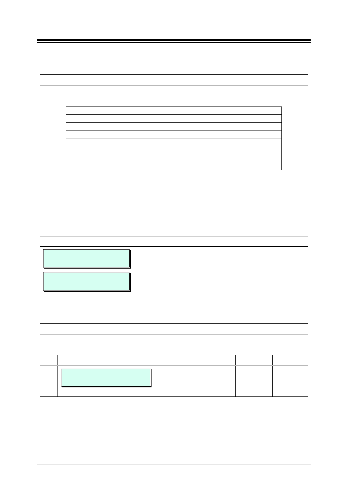
iPECS eMG80 & eMG800 & UCP
Press the [Save] button to store the data entry.
Table 3.3.3.10-1 IDLE LINE SELECTION TYPE & VALUE (PGM 121)
TYPE
VALUE
DESCRIPTION
Flex button
Flex button, activates Flex Number as if dialed.
CO line
CO/IP path seizes CO line.
CO group
CO/IP Group seizes CO line from the CO/IP Group.
Station
Station, calls the assigned station
Hunt Group
Call to Hunt Group
Station Speed
Call to Station Speed
System Speed
Call to System Speed
Attribute, refer to Table 3.3.3.11-1.
[Save]
H.323 or SIP VoIP calls.
Administration and Programming Manual Issue 1.6
Use the dial-pad to enter the type and value for the desired
Idle Line selection, refer to Table 3.3.3.10-1.
1
2
3
4
5
6
7
3.3.3.11 Station IP Attributes – PGM 122
Stations are allowed access to the systems H.323 VoIP resources based on the Station IP
Attributes. Refer to Table 3.3.3.11-1 for a description of the attributes and the inputs available.
PROCEDURE:
STATION IP ATTRIBUTE
ENTER STA RANGE
100-110 STA IP ATT
PRESS FLEX KEY (1)
Press the desired Flex button; refer to Table 3.3.3.11-1.
Use the dial-pad to enter desired data for the Station IP
Press the
Table 3.3.3.11-1 STATION IP ATTRIBUTES (PGM 122)
BTN ATTRIBUTE/DISPLAY DESCRIPTION RANGE DEFAULT
1
100-110 DTR IP CALL
(1:EN/0:DIS) : ENABLE
1. Press the [PGM] button and dial 122.
Use the dial-pad to enter a station range (Ex. 100~110). For
a single station, enter the same number twice.
button to store the data entry.
Enables station to access an IP
channel directly by dialing the IP
Group access code to place
0: Disable
1: Enable
Enable
61
Page 77
iPECS eMG80 & eMG800 & UCP
Attribute, refer to Table 3.3.3.12-1.
[Save]
1.
Administration and Programming Manual Issue 1.6
3.3.3.12 Station Timers – PGM 123
Certain timers can be assigned on a station basis. Available timers, description and valid inputs
are given in Table 3.3.3.12-1.
PROCEDURE:
STATION TIMERS
ENTER STA RANGE
100-110 STATION RANGE
PRESS FLEX KEY (1-2)
1. Press the [PGM] button and dial 123.
Use the dial-pad to enter a station range (Ex. 100~110). For
a single station, enter the same number twice.
Press the desired Flex button.
Use the dial-pad to enter desired data for the Station IP
Press the
button to store the data entry.
Table 3.3.3.12-1 STATION TIMERS (PGM 123)
BTN ATTRIBUTE/DISPLAY DESCRIPTION RANGE DEFAULT
1
STA FWD NO ANS TMR (sec)
(000-600) : 000
This timer determines the
duration the station will ring prior
to Ring-No-Answer Forward.
This setting affects both manual
and Preset Call Forward and
overrides the System Ring No
Answer timer PGM 181-button
000-600
seconds
000
2
CUT OFF (Min)
(00-99) : 00
Allowed length of CO/IP calls
when station is assigned Call
Time restriction in Station
Attributes II, PGM 112, button 3
00-99
minutes
00
62
Page 78
iPECS eMG80 & eMG800 & UCP
3.3.3.13-1.
Press the [Save] button to store the data entry.
delete the device from the system.
Administration and Programming Manual Issue 1.6
3.3.3.13 Linked Station Table – PGM 124
A station can be linked to another station so that the two stations effectively act as a single station
with the attributes of the primary station number. An unregistered or registered station may be
linked to a primary station. When unregistered station linking is used, the linked station does not
reduce the system’s capacity.
PROCEDURE:
LINKED STA TABLE
ENTER STA NUMBER
STA 110 IS LINKED PAIR
PRESS FLEX KEY (1-3)
1. Press the [PGM] button and dial 124.
Use the dial-pad to enter primary station number for the
Linked pair (Ex. 110).
Press the desired Flex button.
Use the dial-pad to enter desired data, refer to Table
Table 3.3.3.13-1 LINKED STATION ATTRIBUTES (PGM 124)
BTN ATTRIBUTE/DISPLAY DESCRIPTION RANGE DEFAULT
1
2
3
SET IP ADDRESS
IP: IP NOT ASSIGNED
ROUTER IP ADDRESS
IP: ROUTER IP NOT ASSIGN
STA 110 : SET MAC ADDR
MAC: NOT ASSIGNED
IP Address of the linked station not
required.
Set Router IP address associated with
linked station.
Set MAC address of linked un-registered
station, required data. Note the
secondary station must not be registered
in the system prior to linking. If needed,
63
Page 79
iPECS eMG80 & eMG800 & UCP
station number of the Group Attendant.
LED OFF: group access denied
Press the [Save] button to store the data entry.
Administration and Programming Manual Issue 1.6
3.3.3.14 ICM Tenancy Group – PGM 125
Stations can be assigned to an ICM Tenancy group under Station Attributes II PGM 111, button
17. Up to 15 Tenant groups for eMG80 and up to 32 for eMG800 can be defined. Each group is
configured to allow or deny placing intercom calls to stations in other groups and an Attendant
station can be defined for each group. The Attendant will receive “dial 0” calls and controls
Day/Night mode for the Group.
PROCEDURE:
ICM TENANCY GROUP
ENTER GRP NUMBER (01-15)
ICM TENANCY GRP 01
F1:ATD F2:ACCESS
1. Press the [PGM] button and dial 125.
Use the dial-pad to enter the group number (Ex. 01)
Press the desired Flex button; refer to Table 3.3.3.14-1.
For Attendant assignment, use the dial-pad to enter the
To assign accessible ICM Tenancy groups for the group, the
Flex button indicates the current Tenant group access.
Press the Flex.
Buttons to toggle Group access settings.
LED ON: group access allowed
Table 3.3.3.14-1 ICM TENANCY GROUP ATTRIBUTES (PGM 1 25)
BTN ATTRIBUTE/DISPLAY DESCRIPTION RANGE DEFAULT
1
2
ICM TENANCY GRP 01
ATD: . . . .
ICM TENANCY GRP 01
PRESS ACCESS GRP(1-15)
Attendant station for the ICM
tenancy group. ATD. Receives dial
‘0’ calls and controls Day/Night
mode.
ICM Tenancy groups allowed
access to the selected group.
STA No -
eMG80:01-15
eMG800:01-32
GROUP 1
64
Page 80
iPECS eMG80 & eMG800 & UCP
Press the [Save] button to store the data entry.
be set at PGM 253.
played.
played, call is hanged up.
notification.
Administration and Programming Manual Issue 1.6
3.3.3.15 Station VM Attributes – PGM 127
Voice Mail attributes can be assigned on a station basis. The description and valid inputs are
given in Table 3.3.3.15-1.
PROCEDURE:
ENTER PGM NUMBER
STATION VM ATT
ENTER STA RANGE
100-110 STA VM ATT
PRESS FLEX KEY (01-20)
1. Press the [PGM] button and dial 127.
Enter Station Range.
Press the desired Flex button.
Use the dial-pad to enter desired data, refer to Table
3.3.3.15-1.
Table 3.3.3.15-1 STATION VM Attributes (PGM 127)
BTN − ATTRIBUTE/DISPLAY DESCRIPTION RANGE DEFAULT
1
2
VM COS
(1-5) : 1
ADMINISTRATOR MAILBOX
(1:EN/0:DIS):DISABLE
Voice Mail COS (Grade) can be set on
each station. Each COS attributes can
If this option is set to ON, Administrator
Voice Mail feature can be accessed.
1-5 1
0: Disable
1: Enable
Disable
3
4
5
6
7
8
ANNC. ONLY MAILBOX
(1 :EN/0 :DIS) :DISABLE
ANNC. ONLY OPTION
(0-1):PREVIOUS MENU
COMPANY DIR FIRST NAME
…............
COMPANY DIR LAST NAME
…............
USER-MSG RW/FF TIME
(03-99):04 Sec
NOTIFY REPEAT COUNT
(00-99) : 03
If this option is set to ON, no message
can be left and only the greeting is
This option is available only ANNC.
ONLY MAIL BOX is set to ON.
If Previous Menu, after greeting
message is played, go to previous
menu.
If Hang Up, after greeting message is
This field is first name of a station for
Company Directory feature.
This field is last name of a station for
Company Directory feature.
User Message Rewind / Fast Forward
are supported by this time.
It is used to transfer call to attendant if
retry count is over this for VM
0: Disable
1: Enable
0: Previous
1: Hang Up
Max 12 Char N/A
Max 12 Char N/A
03-99 04
00-99 03
Disable
Previous
menu
65
Page 81
iPECS eMG80 & eMG800 & UCP
notification.
that
originating
mailbox. This field is
2: Move
2:All
after cascade timer.
Administration and Programming Manual Issue 1.6
Table 3.3.3.15-1 STATION VM Attributes (PGM 127)
BTN − ATTRIBUTE/DISPLAY DESCRIPTION RANGE DEFAULT
9
10
11
12
13
14
15
16
NOTIFY DIAL TIME
(00-99) : 15 Sec
FORWARD OPTION
(0-1) : MOVE
CASCADE MAILBOX1
….
CASCADE MAILBOX2
….
CASCADE MAILBOX3
….
CASCADE MAILBOX4
….
CASCADE MAILBOX5
….
CASCADE METHOD
(0-2) : DISABLE
It is dial waiting time after provide
VMIU/VMIB announcement for VM
When a left message is forwarded, this
option is applied.
Message ca scading i s a f eature
copies messages left for the
mailbox to another
destination mail box station.
Cascade method is determined.
00-99
(seconds)
0:Move
1: Copy
Station No. N/A
0:Disable
1: Copy
15
Move
Disable
17
18
19
20
CASCADE MESG TYPE
(0-2) : NORMAL ONLY
CASCADE APPLY TYPE
(0-2) : IMMEDIATE
CASCADE TMR(min)
(000-250) : 000
MSG WAIT NOTICE
(0-2) : TONE
Cascade Message Type is determined.
Cascade Apply Type is determined.
Immediate: Cascade is done as soon
as a message is left.
After Notify Retry Count: After Notify
Retry Count is over, cascade is done.
After Cascade Timer: Cascade is done
Cascade Apply Timer is set.
When a user has voice mail, system
can provides this as voice prompt
instead of dial tone according to option
based on station.
Disable: System provides normal dial
tone when a user goes to off hook
status.
Tone: System provides warning tone
instead of dial tone to give indication
when a user goes to off hook status.
Prompt: System provides message
indication as voice prompt when a user
goes to off hook status.
0:Normal Only
1: Urgent Only
0:Immediate
1: After Notify
Retry Count
2: After
Cascade
Timer
000 ~250
(min)
0: OFF
1:Tone
2:Prompt
Normal
only
Immediate
0
Tone
66
Page 82
iPECS eMG80 & eMG800 & UCP
The destination is 14 kinds.
If this option is set to OFF, this CCR
regarded as DISA dialing.
affected to the DISA routing.
Message
Message
Administration and Programming Manual Issue 1.6
3.3.3.16 Station CCR Table – PGM 128
CCR Table can be assigned on a station basis. The description and valid inputs are given in
Table 3.3.3.16-1.
PROCEDURE:
ENTER PGM NUMBER
STATION CCR
ENTER STA RANGE
100-110 STA CCR
PRESS FLEX KEY (01-14)
1. Press the [PGM] button and dial 128.
Enter Station Range (Ex. 100~110).
Press the desired Flex button.
Press the desired Flex button; refer to Table 3.3.3.16-1.
Table 3.3.3.16-1 STATION CCR Table (PGM 128)
BTN ATTRIBUTE/DISPLAY DESCRIPTION RANGE DEFAULT
1-10
11
101 – 110 STA CCR
INPUT 0 : NOT ASSIGNED
101 – 110 CCR TBLUSAGE
(1:ON/0:OFF) : OFF
Button 1 to 10 means outside user
press 1 to 0. This dialing is matched
with this table destination.
If this option is set to ON, this CCR
table is worked.
table is not worked, instead of that,
outside caller’s dialed digit can be
NA
OFF
ON
OFF
12
13
14
101 – 101 CCR 1 DGT ONLY
(1:ON/0:OFF) : OFF
101 – 101 * USED AS
(0-3): NUMBERING PLAN
101 – 101 # USED AS
(0-3): ACCESS MAILBOX
If this option is set to ON, Only the
first digit that is user entered is
affected to the CCR routing.
If this option is set to OFF, the
following next digits are also
While listening User Greeting, *
button working is followed by this
attribute.
While listening User Greeting, #
button working is followed by this
attribute.
ON/OFF OFF
0 : Numbering
Plan
1 : Replay
Greeting
2 : Access
Mail Box
3 : Leave
0 : Numbering
Plan
1 : Replay
Greeting
2 : Access
Mail Box
3 : Leave
Numbering
Plan
Access
Mailbox
67
Page 83
iPECS eMG80 & eMG800 & UCP
Route to a Station
Route to a Hunt Group
Route with System Speed Dial
Route as PBX Transfer with System Speed Dial (Flash then dial speed dial digits)
Route to VSF Announcement
Route to VSF Announcement and disconnect
Route to Networked Station
Conference Room
Internal Page
External page
All Call Page
Route to voice mail (Hunt group/station number)
Company Directory (USA Only)
Record VM Greeting (USA Only)
Chart.
[Save]
Administration and Programming Manual Issue 1.6
Table 3.3.3.16-1 CCR DESTINATIONS (PGM 128)
TYPE
1
2
3
4
5
6
7
8
9
10
11
12
13
14
DESCRIPTION
3.3.3.17 LSS Label Edit – PGM 129
The LIP-8012 LSS 12 button DSS Console incorporates an LCD used to label the function of
each button. The label, which can be up to 12 characters, is assigned in this program.
PROCEDURE:
LSS LABEL EDIT
ENTER STA NUMBER
STA 100 LSS LABEL
ENTER LSS IDX(1-4)
STA 100 LSS 1
ENTER BTN NO (01 – 12)
1. Press the [PGM] button and dial 129.
Use the dial-pad to enter the station number associated with
the console (Ex. 100).
Consoles are indexed, allowing multiple consoles to be
associated with a station. Use the dial-pad to enter the index
of the LSS console (1 ~ 4).
STA 100 LSS 1 BTN 1
LABEL IS EMPTY
Use the dial-pad to enter the desired LSS console button
number (1 ~ 12).
Edit the label referring to Table 2.1.2-1 Alpha-numeric Entry
Press the
button to store the data entry.
68
Page 84
iPECS eMG80 & eMG800 & UCP
3.3.4.1-1.
[Save]
Start mode.
Administration and Programming Manual Issue 1.6
3.3.4 BOARD DATA – PGM 130 to 132
3.3.4.1 H.323 VoIP Attributes – PGM 130
The VOIP channels are used for Distributed Networking, access to SIP or H.323 networks and for
remote iPECS devices. When the standard H.323 VoIP protocol is employed for an external VoIP
call, several attributes of these channels can be assigned. The H.323 call set-up mode and
tunneling (H.245 Encapsulation) can be established.
Also for H.323 support, a RAS (Registration, Admissions and Status) channel can be defined.
The RAS channel IP addresses (uni-cast and multi-cast) as well as the IP port Numbering Plan
and other H.323 set-up characteristics are defined.
This PGM also allows setting the IP TOS bit for Diffserv, a commonly recognized packet
prioritization protocol. Higher priority packets are given priority in the Router or Layer 3 Switch
queue. However, they are the first to be discarded in the event of long queue delays, which may
cause excess packet loss and poor voice quality.
Refer to Table 3.3.4.1-1 for a description of the features and the input required.
PROCEDURE:
H323 VOIP ATTRIBUTE
ENTER SEQ NO(001-300)
001 H323 VOIP ATTR
PRESS FLEX KEY (01-24)
1. Press the [PGM] button and dial 130. eMG800 range is
0001-2890.
Use the dial pad to enter the VoIP board sequence number.
Press the desired Flex button; refer to Table 3.3.4.1-1.
Use the dial pad to enter the desired data, refer to Table
Press the
button to store the data entry.
Table 3.3.4.1-1 H.323 VOIP ATTRIBUTES (PGM 130)
BTN ATTRIBUTE/DISPLAY DESCRIPTION RANGE DEFAULT
1
2
3
H.323 SETUP MODE
(1:FAST/0:NORM): FAST
H.323 TUNNEL MODE
(1:ON/0:OFF) : ON
H.323 DTMF PATH
(0:IN/1:OUT/2:2833): 0
H.323 IP calls can be set-up
using the H.323 normal or Fast
H.323 IP calls can be set-up
using the H.245 encapsulation
(Tunneling).
During a connection, DTMF Digits
can be sent in-band or out of
band (H.245).
0: Fast
1: Norm
0: OFF
1: ON
0: In band
1: Out band
2: 2833
Fast
ON
0
4
DIFFSERV PRETAG
TAG (00-63) : 04
Diffserv pre-tagging for Voice
packet. Note high values may
cause high packet discard levels.
69
0~63 4
Page 85
iPECS eMG80 & eMG800 & UCP
Gatekeeper.
and VOIB/VOIU.
Admin).
full RRQ message (OFF).
connection.
ON).
case of outgoing call.
Administration and Programming Manual Issue 1.6
Table 3.3.4.1-1 H.323 VOIP ATTRIBUTES (PGM 130)
BTN ATTRIBUTE/DISPLAY DESCRIPTION RANGE DEFAULT
5
RAS USAGE
(1:ON/0:OFF) : OFF
Determine whether VOIU/VOIB
Board will be used as a
0: OFF
1: ON
OFF
6
7
8
9
10
11
12
13
RAS MULTICAST IP
224.0.1.41
RAS MULTICAST PORT
(00001-65535): 01718
RAS UNICAST IP
82.134.80.2
RAS UNICAST PORT
(00001-65535): 01719
RAS KEEP_ALIVE TM
(001-999) : 120 (sec)
RAS NUM PLAN PREFIX
9
RAS GATEWAY ID
ONLY POSSIBLE BY WEB ADM
RAS LIGHT RRQ
(1:ON/0:OFF) : OFF
Multi-cast IP address for RAS
Information of Gatekeeper.
Multi-cast IP Port for RAS
Information of Gatekeeper.
Uni-cast IP address for RAS
Information of Gatekeeper.
Uni-cast IP Port for RAS
Information of Gatekeeper.
The time between exchange of
RAS Information between GK
The numbering plan for Calling
Number in RAS Setup.
The Gatekeeper ID (This can be
programmed only via WEB
The system can be assigned to
use the simple RRQ (Registration
Request) message (ON) or the
IP Address 224.0.1.41
IP Port # 1718
IP Address 82.134.80.2
IP Port # 1719
001-999
(SEC)
Number
(24 digits)
128 Character
0: OFF
1: ON
120
9
OFF
14
15
16
17
18
19
TCP KEEP ALIVE
(1:ON/0:OFF) : ON
FAIL OVER USAGE
(1:ON/0:OFF) : OFF
FAIL OVER TIME(sec)
(03-10) : 05
FAIL OVER CO GRP
(01-21) : . .
Q931 START PORT
(00001-65535) : 02048
Q931 END PORT
(00001-65535) : 02559
The system will send a polling
message every 75 seconds to
assure the status of the TCP
The H.323 call will be failover to
another line (FAIL OVER USAG:
The H.323 call will be failover.
The time will be set.
If the H.323 call will be failover,
assign another CO group.
IP-Binding H.323 signaling
option: Q.931 TCP Start Port in
case of outgoing call.
IP-Binding H.323 signaling
option: Q.931 TCP End port in
0: OFF
1: ON
0: OFF
1: ON
03-10
(Sec.)
01-21
00001-65535 2048
00001-65535 2559
ON
OFF
5
70
Page 86
iPECS eMG80 & eMG800 & UCP
media on receiving the
Alerting message.
Administration and Programming Manual Issue 1.6
Table 3.3.4.1-1 H.323 VOIP ATTRIBUTES (PGM 130)
BTN ATTRIBUTE/DISPLAY DESCRIPTION RANGE DEFAULT
20
H245 START PORT
(00001-65535) : 02560
P-Binding H.323 signaling option:
H.245 TCP Start Port.
00001-65535 2560
21
22
23
24
24-1
24-2
24-3
24-4
H245 END PORT
(00001-65535) : 03071
RAS START PORT
(00001-65535) : 02048
RAS END PORT
(00001-65535) : 03071
001 H323 VOIP ATTR (2ND)
PRESS FLEX KEY (1-4)
MEDIA START PORT
(00001-65535) : 06000
MEDIA END PORT
(00001-65535) : 07036
DATA START PORT
(00001-65535) : 08500
DATA END PORT
(00001-65535) : 08548
IP-Binding H.323 signaling
option: H.245 TCP End Port.
IP-Binding H.323 signaling
option: RAS UDP Start Port.
IP-Binding H.323 signaling
option: RAS UDP End Port.
IP-Binding media option: Media
UDP Start Port.
IP-Binding media option: Media
UDP End Port.
IP-Binding option: Data Sharing
TCP Start Port.
IP-Binding option: Data Sharing
TCP End Port.
00001-65535 3071
00001-65535 2048
00001-65535 3071
00001-65535 6000
00001-65535 7036
00001-65535 8500
00001-65535 8548
24-5
24-6
24-7
H.245 SETUP
(1:ON/0:OFF) : OFF
H.245 PROCEEDING
(1:ON/0:OFF) : OFF
H.245 ALERTING
(1:ON/0:OFF) : OFF
This feature is the ability of two
user endpoints to communicate
before call is actually established
in normal call mode. This feature
is not used when 'H323 Setup
Mode' is 'Fast'.
* Setup: Caller party tries to open
early media on receiving the
Setup message.
* Proceeding: Calling party tries
to open early media on receiving
the Proceeding message.
* Alerting: Calling party tries to
open early
0: OFF
1: ON
0: OFF
1: ON
0: OFF
1: ON
OFF
OFF
OFF
71
Page 87
iPECS eMG80 & eMG800 & UCP
Sequence Numbers. (e.g. enter the sequence number
3.3.4.2-1.
[Save]
ESF: Use Data link Message.
disabled (OFF).
3:CONGES_DIS
DISPLAY). (USA only)
Administration and Programming Manual Issue 1.6
3.3.4.2 T1/E1/PRI Attributes – PGM 131
Each T1/PRI module can be assigned for various attributes of the interface. The T1 interface
framing and line coding can be selected and, for the PRI, TE or NT operation and CRC check can
be selected. Refer to Table 3.3.4.2-1 for a description of the features and the input required. Note
that the Sequence Number can be determined in PGM 103, Button 1.
PROCEDURE:
T1 /E1/PRI ATTRIBUTE
ENTER SEQ NO ( 001 –300 )
001 T1 /PRI ATTR
PRESS FLEX KEY ( 1 – 7 )
1. Press the [PGM] button and dial 131 and enter sequence
number (Ex. 001). eMG800 range is 0001-2890.
Use the dial pad to enter the Sequence Number of the
desired T1/PRI module. Use PGM 103 to determine
Press the desired Flex button; refer to Table 3.3.4.2-1.
Use the dial pad to enter the desired data, refer to Table
Press the
button to store the Table data entry.
Table 3.3.4.2-1 T1/PRI MODE (PGM 131)
BTN ATTRIBUTE/DISPLAY DESCRIPTION RANGE DEFAULT
1
T1 SETUP MODE
(1:ESF/0:D4) : D4
2
T1 LINE MODE
(1:AMI/0:B8ZS) : B8ZS
Select T1 Setup mode.
D4 frame: Use In-Band Control
Protocol.
Select T1 line mode (AMI/B8ZS). 0: B8ZS
0: D4
1: ESF
1: AMI
D4
B8ZS
3
PRI LINE MODE
(1:TE/0:NT): TE
4
PRI/E1 CRC CHECK
(1:ON/0:OFF): OFF
5
E1 R2DSP CHECK
(1:ON/0:OFF): OFF
6
DCO PX TYPE
(0-3): STANDARD (2)
7
CALLER NAME TYPE
(1:DISP/0:FAC) : FACILIT
Select TE/NT mode. 0: NT
1: TE
For PRI lines the CRC (Cyclical
Redundancy Check) can be
Used for R2-El board or E1 board. 0: OFF
Reserved for future use with R2 E1
board.
If the caller has a name, the Caller
Name is sent to the network
according to the option (FACILITY,
0: OFF
1: ON
1: ON
0: S1240
1: TDX1B
2: STANDARD
0:FACILITY
1:DISPLAY
TE
OFF
OFF
STANDARD
FACILITY
72
Page 88
iPECS eMG80 & eMG800 & UCP
Numbers.
3.3.4.3-1.
[Save]
devices.
PGM 161-button 9.
devices.
use, IPSec may be disabled.
Administration and Programming Manual Issue 1.6
3.3.4.3 Board Base Attributes – PGM 132
Appliances (Boards and IP Phones) can be connected to the iPECS over a managed WAN
without the need to employ a VoIP channel. In this case, the system does not implement security
(IPSec) or QoS treatment over the link. To implement the managed WAN connectivity, the iPECS
must be assigned with the IP address of the router for all appliances that may attempt a point-topoint connection over the managed WAN, including devices on the iPECS LAN. Note that if the
device’s Router IP address is not defined, the system will use the Router IP address defined in
PGM 102.
The default codec employed by each device can be specifically defined as G.711, G.723, G.729,
G.722 or the system default codec PGM 161 can be defined.
Note that the Sequence Number can be determined in PGM 103, Button 1.
PROCEDURE:
BOARD BASE ATTRIBUTE
ENTER RANGE (001–300 )
001-002 BOARD ATTRIBUTE
PRESS FLEX KEY (01–13)
1. Press the [PGM] button and dial 132 and enter Range
(Ex. 001~002). eMG800 range is 0001-2890.
Use the dial pad to enter the Sequence Number range of the
desired module. Use PGM 103 to determine Sequence
Press the desired Flex button; refer to Table 3.3.4.3-1.
Use the dial pad to enter the desired data, refer to Table
Press the
button to store the Table data entry.
Table 3.3.4.3-1 BOARD ATTRIBUTES (PGM 132)
BTN ATTRIBUTE/DISPLAY DESCRIPTION RANGE DEFAULT
1
2
001-002 ROUTER IP ADDR
0 .0 .0 .0
001-002 DEV CODEC TYPE
(0-4): SYSTEM CODEC
Enter the default Router IP address
associated with the selected
Select the CODEC type for the
selected devices:
0: G.711,
1: G.723.1,
2: G.729,
3: G.722
4: System Codec refer to
0.0.0.0
0-4 4
3
4
001-002 FIRWALL IP ADDR
0 .0 .0 .0
001-002 RTP SECURITY
(1:ON/0:OFF) : ON
Enter the Firewall IP address
associated with the selected
Remote iPECS IP & LDP phones
use IPSec to assure a secure
connection. To reduce bandwidth
73
0.0.0.0
0: OFF
1: ON
ON
Page 89
iPECS eMG80 & eMG800 & UCP
circumstance.
VOIB).
triggered.
2: T
Administration and Programming Manual Issue 1.6
Table 3.3.4.3-1 BOARD ATTRIBUTES (PGM 132)
BTN ATTRIBUTE/DISPLAY DESCRIPTION RANGE DEFAULT
5
001-002 TNET ENABLE
(0:ON/0:OFF) : OFF
When a module or station is to
be connected in a Centralized
Control network (TNET), the
device must be enabled for
TNET operation.
0: OFF
1: ON
OFF
6
7
8
9
10
11
12
001-002 VSF SENDER MAIL
. . . . . . . . . . . .
001-002 T38 ENABLE
(1:ON/0:OFF) : OFF
001-002 USE BRD IP FWIP
(1:ON/0:OFF) : OFF
001-002 RTP FIRWALL IP
0 .0 .0 .0
001-002 T38 PORT USAGE
(0:D/1:S/2:T) : 0
001-002 2833 PAYLOAD
(000-127) : 000
001-002 2833 VOLUME
(00-36) : 00
VMIU/VMIB e-mail address for
Mailbox Mail Sending.
T38 mode ON/OFF for FAX data
transfer.
VOIB IP will be used for SIP
signaling in Multi NAT
Enter the Firewall IP address
associated with the Remote Phone
or Gateway/board if there needs
Dual Broadband connection for SIP
trunks and Remote phones (using a
T38 Port can be different with
Voice Port. Or, be same or be
RFC 2833 Payload is
programmable.
RFC 2833 packet volume. 00-36 00
NULL
0: OFF
1: ON
0: OFF
1: ON
0.0.0.0
0: D
1: S
000-127 000
OFF
OFF
0
13
001-002 2833 REDUNDANCY
(1-8) : 0
RFC2833 Packet Redundancy. 1-8 0
74
Page 90
iPECS eMG80 & eMG800 & UCP
Press the [Save] button to store the data entry.
Table 3.3.5.2-3.
Administration and Programming Manual Issue 1.6
3.3.5 CO LINE DATA – PGM 140 to 151
3.3.5.1 CO Service Type – PGM 140
Each CO Line is assigned a type, Normal or DID. Normal CO Lines can be employed for DISA
Service PGM 146. DID lines are for incoming only operation and provide call routing based on
signaling from the carrier, refer to section 3.3.5.4 DID Service Attributes - PGM 145.
PROCEDURE:
COL SERVICE ATT
ENTER COL RANGE
01-02 SVC TYPE
PRESS FLEX KEY (1-1)
01-02 SVC TYPE (1-4)
NORMAL CO (1)
1. Press the [PGM] button and dial 140 and enter the range
(Ex. 0102).
2. Press the desired Flex button.
Use the dial pad to enter a CO Line range. For a single CO
Line, enter the same number twice.
Use the dial pad to enter the desired service type:
1. Normal CO line
2. DID line
3. TIE line
4. Unused
3.3.5.2 CO/IP Attributes I ~ III - PGM 141~143
CO/IP Attributes define various characteristics of the CO lines and IP facilities under control of the
system. Most require a dial pad input of 1 or 0 to set the characteristic, refer to Table 3.3.5.2-1 to
Table 3.3.5.2-3. Specific descriptions for Class-of-Service and CO line Call Metering tones are
provided in Table 3.3.5.2-4 and Table 3.3.5.2-5 respectively.
PROCEDURE:
CO/IP ATTRIBUTE 1
ENTER COL RANGE
01-02 CO/IP ATT 1
PRESS FLEX KEY (01-24)
Press the desired Flex button; refer to Table 3.3.5.2-1 to
1. Press the [PGM] button and dial:
141 for CO/IP Attributes I
142 for CO/IP Attributes II
143 for CO/IP Attributes III.
Use the dial-pad to enter a CO/IP line range. For a single
CO/IP Line, enter the same number twice.
75
Page 91
iPECS eMG80 & eMG800 & UCP
to Table 3.3.5.2-1 through Table 3.3.5.2-5.
[Save]
no restrictions.
analogue CO Line.
dialing the UNA code.
access.
Administration and Programming Manual Issue 1.6
PROCEDURE:
Use the dial-pad to enter desired data for the Attribute, refer
Press the
button to store the data entry.
Table 3.3.5.2-1 CO/IP ATTRIBUTES I (PGM 141)
BTN ATTRIBUTE/DISPLAY DESCRIPTION DEFAULT
1
2
3
4
01-02 CO/IP GROUP
GRP NO (01-20) : 01
01-02 CO LINE COS
COS (1–5) : 1
01-02 CO START SIGNAL
(1:GND/0:LOOP) : LOOP
01-02 CO LINE TYPE
(1:PBX/0:CO) : CO
Each CO Line is assigned to a group;
grouping should be based on the Line type
and COS.
Each CO Line is assigned a Class-of-Service
which will interact with the Station COS, refer
to section 3.3.5.2.
CO COS 1: Station COS applies
CO COS 2: Exception Table A governs
CO COS 3: Exception Table B governs
CO COS 4: Restricts LD calls and Exception
Table C
CO COS 5: Overrides Station COS 2~6 with
The system can recognize a loop closure or a
ground as the “connect” (start) signal on an
Each CO Line can be assigned as connected
to a CO Line or a PBX/CTX Line.
LOOP
CO
01
1
5
6
7
8
9
10
01-02 CO LINE SIGNAL
(1:DTMF/0:PULSE):DTMF
01-02 UNSED
01-02 UNIVERSAL ANS
(1:ON/0:OFF) : OFF
01-02 CO/IP GRP AUTH
(1:ON/0:OFF) : OFF
01-02 DATA STATION NO
FAX : ….
01-02 TENANCY GROUP
(00-15) : 00
Each analogue CO Line can be assigned to
send either DTMF or Pulses for dialed digits
to the PSTN.
Universal Night Answer (UNA) allows any
station to answer a call on the CO Line by
Each CO/IP Group can be assigned to require
the user enter an Authorization Code for
Each CO/IP line can be assigned to recognize
a FAX call when a specified station answers.
Only stations in the assigned Tenancy group
are permitted access to the defined CO Line.
DTMF
OFF
OFF
….
00
76
Page 92
iPECS eMG80 & eMG800 & UCP
6:SIP/RTP RLY
to the DID/DISA Destination - PGM 167.
Administration and Programming Manual Issue 1.6
Table 3.3.5.2-1 CO/IP ATTRIBUTES I (PGM 141)
BTN ATTRIBUTE/DISPLAY DESCRIPTION DEFAULT
11
01-02 CO VOIP MODE
VOIP MODE(1-6) : COMMON
The VOIB channels can support iPECS,
H.323 or SIP protocols. This field defines the
protocol for the VoIP channel(s).
1: COMMON
2:H.323 ONLY
3: SIP ONLY
4:RTP RLY
5:H.323/RTP RLY
COMMON
12
13
14
15
16
17
18
01-02 PROCTOR ON/OFF
(1:ON/0:OFF) : OFF
01-02 WAIT IF VSF BUSY
(1:ON/0:OFF) : ON
01-02 UNUSED
01-02 UNUSED
01-02 RING TONE
(00-12, 0:N/A) : 00
01-02 UNUSED
01-02 GAIN TABLE
(1-3) : 1
Each analogue CO line can be assigned to
send the station number as DTMF digits for
Proctor service.
When a DID/DISA call assigned to receive a
VMIU/VMIB announcement arrives and all
channels are busy, the call may wait with Ring
back until a channel is available (ON) or route
Ring Tone can be programmable by CO-line
base admin.
TDM gain table can be programmed. 1
OFF
ON
00
19
20
21
01-02 TONE TBL
(1-5) : 1
01-02 DGT CONV. TBL
(01-15) : 01
01-02 PREPAID CALL
(1:ON/0:OFF) : OFF
Tone table can be programmed. 1
Select digit conversion table. 01
Enables Pre-paid Call feature. OFF
77
Page 93
iPECS eMG80 & eMG800 & UCP
money that has been used.
to the station/co line.
Name - ICLID feature is operated with Name
emergency call.
character name, if assigned.
character entry sequence.
3.3.5.2-5.
227.
Administration and Programming Manual Issue 1.6
Table 3.3.5.2-1 CO/IP ATTRIBUTES I (PGM 141)
BTN ATTRIBUTE/DISPLAY DESCRIPTION DEFAULT
22
01-02 PREPAID MONEY
0 (USED:0)
An amount can be associated with the station
as prepayment for outgoing calls. The
assigned “Pre-paid Money” is reduced by the
calculated call cost (Call Metering or
cost/minute). This parameter displays the
remaining funds for outgoing calls. Prepaid
Money is often used in small hospitality
businesses.
The “Used Pre-paid Money” displays the
23
24
24-1
24-2
01-02 LDT ZONE
(001-100) : 001
ADDED CO/IP ATTRIBUTE 1
PRESS FLEX KEY (1-2)
01-02 ICLID USAGE
(0-2) : CLI
01-02 EMERGENCY PBX C
(0-4) : DISABLE
If the LDT Zone Number of a station/co line is
equal to this value, this LDT table is available
An incoming call can be routed to the
destination based on Calling Name.
Disable - ICLID feature is disabled
CLI - ICLID feature is operated with CLI
System can insert PBX code automatically if
pre-configured when a user make an
001
CLI
Disable
Table 3.3.5.2-2 CO/IP ATTRIBUTES II (PGM 142)
BTN ATTRIBUTE/DISPLAY DESCRIPTION DEFAULT
1
2
01-02 CO NAME DISPLAY
(1:ON/0:OFF) : OFF
01-02 CO NAME ASSIGN
…………
The IP Phone display can indicate the CO
Line/IP channel number or a twelve (12)-
Each CO Line and the IP group can be
assigned a twelve (12) character name for
display purposes, see Table 3.1.2-1 for
OFF
3
4
5
01-02 METERING UNIT
00:NONE (0-6)
01-02 LINE DROP(CPT)
(1:ON/0:OFF) : OFF
01-02 DISA ACCT CODE
(1:ON/0:OFF) : ON
Selects the call-metering signal from the
PSTN to indicate call cost, refer to Table
Each CO Line can be programmed to
disconnect if an error tone is detected.
With DISA ACCT CODE “ON”, users will be
required to enter an Authorization code. Enter
codes in Authorization Codes Table - PGM
78
00
OFF
ON
Page 94
iPECS eMG80 & eMG800 & UCP
10:VSF MOH3
disable ICLID routing.
Administration and Programming Manual Issue 1.6
Table 3.3.5.2-2 CO/IP ATTRIBUTES II (PGM 142)
BTN ATTRIBUTE/DISPLAY DESCRIPTION DEFAULT
6
01-02 MOH: (00-10)
MUSIC 1 (01)
A held call can be connected to one (1) of
three (3) possible audio sources while on Hold
as Music-on-Hold (MOH).
00:REFER TO SYS HOLD
01: INT music
02: EXT music
03: VSF MOH
04: SLT MOH1
05: SLT MOH2
06: SLT MOH3
07: SLT MOH4
08: SLT MOH5
09: VSF MOH2
01
7
8
9
10
11
12
13
14
01-02 CO DIAL TONE
(1:ON/0:OFF) : ON
01-02 CO RBACK TONE
(1:ON/0:OFF) : OFF
01-02 CO ERROR TONE
(1:ON/0:OFF) : OFF
01-02 CO BUSY TONE
(1:ON/0:OFF) : OFF
01-02 DISA CO ACCESS
(1:ON/0:OFF) : OFF
01-02 FLASH TMR
(000-300 10 ms) : 050
01-02 OPEN LOOP
(00-20 100ms) : 04
01-02 ICLI DT TMR
(00-20 SEC) : 00
ISDN Lines may provide a digital signal rather
than actual tones.
If the ISDN tone is set to “OFF”, iPECS can
provide the tones.
Permits DISA users access to the VoIP
facilities of the system.
This entry sets the duration of a Flash on the
CO Line.
This entry sets the duration of open loop that
will be recognized as a “Disconnect Signal”.
When a call is received, the system may use
the ICLID (Incoming Caller ID) to route the
call. The system will delay routing a call for
this timer while awaiting ICLID. Enter a 00 to
ON
OFF
OFF
OFF
OFF
050
500 msec
04
00
15
16
01-02 SMS OUTGOING
(1:EN/0:DIS) : DISABLE
01-02 SMS RCV STATION
STA : ….
Each CO line can be assigned to support
PSTN SMS.
When a PSTN SMS is received, the system
delivers the message to the assigned station.
79
Disable
….
Page 95
iPECS eMG80 & eMG800 & UCP
10:VSF MOH3
rejected.
DIALING TABLE (PGM 206)
played after this timer.
connected after DISA Answer Timer.
201- entry defined by this parameter.
Administration and Programming Manual Issue 1.6
Table 3.3.5.2-2 CO/IP ATTRIBUTES II (PGM 142)
BTN ATTRIBUTE/DISPLAY DESCRIPTION DEFAULT
17
01-02 DL TN:(00-10)
DIAL TONE (00)
One of eleven dial tones can be used by the
CO line.
00:DIAL TONE
01:INT MUSIC
02:EXT MUSIC
03:VSF MOH
04:SLT MOH1
05:SLT MOH2
06:SLT MOH3
07:SLT MOH4
08:SLT MOH5
09:VSF MOH2
dial tone
18
19
20
21
22
23
24
01-02 RB TN: (00-10)
RING BACK TONE (00)
01-02 REJECT ANONYMOUS
(1:ON/0:OFF) : OFF
01-02 PREFIX TABLE ID
(0-6) : 0
01-02 CO CUT OFF TMR
(00-99 MIN) : 00
01-02 DISA DELAY TMR
(0-9 SEC): 0
01-02 LDT TBT INDEX
(00-10) : 01
01-02 DISA ANS TMR
(0-9 SEC) : 0
One of eleven ring back tones can be used by
the CO line.
When REJECT ANONYMOUS “ON”,
incoming call without Caller ID will be
If prefix table ID is set to 0, then prefix dialing
call cannot be applied.
If prefix table ID is set to (1-6), then prefix
dialing call can be applied with PREFIX
Co base call cut off timer can be set at this
field.
It is only used for Russia.
System is connected to DISA call
immediately, and DISA announcement is
LCR will be operated with LDT table index. 1
It is only used for Russia.
When DISA incoming call, System is
Ring back tone
OFF
0
00
0
0
BTN ATTRIBUTE/DISPLAY DESCRIPTION DEFAULT
1
01-02 COLP TABLE IDX
INDEX : NOT ASSIGNED
Table 3.3.5.2-3 CO/IP ATTRIBUTES III (PGM 143)
When an incoming call on an ISDN Line is
answered, the system will send caller id using
the number from the CLIP/COLP Table –PGM
80
None
Page 96
iPECS eMG80 & eMG800 & UCP
a suffix to the entry in PGM 201.
forwards them in a block, ENBLOCK.
4: SUBSCRIBER
digit.
Fixed identifier option should be employed.
(Except USA version)
with appropriate regional protocol support.
match the ISDN Back bone type.
message Sub-address field.
Administration and Programming Manual Issue 1.6
Table 3.3.5.2-3 CO/IP ATTRIBUTES III (PGM 143)
BTN ATTRIBUTE/DISPLAY DESCRIPTION DEFAULT
2
01-02 CLIP TABLE IDX
INDEX : NOT ASSIGNED
When a call is placed on an ISDN Line, the
system will send caller id using the number
from the CLIP/COLP Table –PGM 201- entry
defined by this parameter. For entry 00, the
CLI STA NO entered in PGM 114-button 6 will
be used in place of the station number. For
other entries, the station number is added as
None
3
4
5
6
01-02 ENBLOCK SENDING
(1:ON/0:OFF) : OFF
01-02 TYPE OF NO(0-4)
NATIONAL (2)
01-02 DID REMOVE NO
(00-99) : 00
02 TEI TYPE
(1:AUTO/0:FIX) : AUTO
This entry determines if the system sends
dialed digits to the ISDN line as they are
received (Overlap) or collects all digits and
For outgoing calls on the ISDN Line, this
parameter defines the “Type of Number Plan”
provided in Calling Party Information Element
of the ISDN call SETUP message.
0: UNKNOWN
1: INTERNATIONAL
2: NATIONAL
3: Unused
When a DID call is received on an ISDN Line,
this entry determines the number of digits that
will be removed starting with the first received
The TEI (Terminal Endpoint Identifier) is a
unique identifier for each device attached to
the ISDN line. When the system shares an
ISDN connection with other devices, the TEI
should be automatic to assure no conflict with
other attached devices.
When the ISDN connection is not shared, the
eMG80 : OFF,
eMG800: ON
2
00
AUTO
7
8
9
10
11
02 ISDN-SS CD/CR
(1:EN/0:DIS) : DISABLE
02 ISDN 1 DGT RM
(1:ON/0:OFF) : OFF
001-002 AOC TYPE (0-5)
NO SERVICE (0)
001-002 ISDN LINE TYPE
(1:U/0:A): U_LAW
01-02 CALLING SUBADDR
(1:ON/0:OFF) : OFF
Permits a user access to ISDN
Supplementary Call Deflection or Call Reroute Service.
Select one digit remove mode in ISDN Called
Digits (for Italy).
When assigned, the system will analyze the
Advice of Charge information in the Facility
Message according to the ETSI specifications
The system will encode voice using the A-law
or u-law PCM format and should be set to
For outgoing calls, the user’s station number
may be included in the ISDN call SETUP
81
Disable
OFF
No Service
u-Law
OFF
Page 97
iPECS eMG80 & eMG800 & UCP
SMDR, LNR, displays, etc.
outgoing call SETUP message.
On.
button 13 above.
forwarding/transferring station.
will be displayed for the entire call duration.
forwarded station.
Administration and Programming Manual Issue 1.6
Table 3.3.5.2-3 CO/IP ATTRIBUTES III (PGM 143)
BTN ATTRIBUTE/DISPLAY DESCRIPTION DEFAULT
12
01-02 IN PREFIX INS
(1:ON/0:OFF) : OFF
Regional ISDN providers may use the Local
Area Prefix code for special services. In cases
where the code is not provided in the
incoming call SETUP message, the system
can insert the Local Prefix and Area code in
OFF
13
14
15
16
01-02 OUT PREFIX INS
(1:ON/0:OFF) : ON
01-02 INT ACCESS CODE
….
01-02 AREA CODE
……
01-02 PREFIX CODE
….
Regional ISDN providers may use the Local
Area Prefix code for special services. The
system can insert the Local Prefix in the
When an incoming call includes the
international Country code in the ISDN call
SETUP message, the Country code will be
included in the station display.
To include the Country code, Incoming Prefix
insertion (button 12 above) and CLI Display
for the station (PGM 114-button 1) must be
Regional ISDN providers may use the Local
Prefix and Area codes for special services.
The system will insert this Local Area Code in
the call SETUP messages defined under
button 13 above.
Regional ISDN providers may use the Local
Prefix and Area codes for special services.
The system will insert this Local Prefix Code
in the call SETUP messages defined under
ON
-
-
17
18
19
01-02 CLI TRANSIT
(1:ORI/0:CFW):CFW
01-02 PRESERVE NAME
(1:ON/0:OFF) : OFF
01-02 REDIRECT INFO
NO SERVICE (0)
When the system must send CLI to the ISDN
for an off-net call, the CLI can be either the
original caller’s CLI or the CLI of the Off-net
For DID lines, the CLI is normally displayed
only during ringing. If enabled here, the CLI
When the system needs to send Redirecting
number to the ISDN for an off-net call, the
Redirecting number can be either the original
caller’s CLI or the CLI of the Off-net
forwarding/transferring station.
If it is no service then system will not send this
information.
If it is OGR CLI (original CLI) then system will
send original CLI that is received from
incoming CO line.
If it is CFW CLI then system will send
redirecting CLI that is CLI for call off-net call
82
CFW
OFF
NO
SERVICE
Page 98
iPECS eMG80 & eMG800 & UCP
chosen.
6: Reserved.
3: Network Provided.
114 – Station CLI 1 to Station CLI 5.
message.
Administration and Programming Manual Issue 1.6
Table 3.3.5.2-3 CO/IP ATTRIBUTES III (PGM 143)
BTN ATTRIBUTE/DISPLAY DESCRIPTION DEFAULT
20
01-02 INC CLI CHOICE
(1:ORI/0:TRANSIT):TRS
Incoming CLI Choice – When ISDN setup
message have two CLI (Transit Point CLI /
Original CLI), by using this option, CLI can be
Transit
21
22
23
01-02 CALLING NUM PLAN
(0-6):ISDN/TELEPHONY (1)
01-02 CALLED NUM PLAN
(0-6) : UNKNOWN (0)
01-02 SCREENING (0-3)
USER PROVIDED, NO S (0)
ISDN Calling Party Numbering Plan can be
programmable.
0: Unknown.
1: ISDN / Telephony.
2: Data / Numbering.
3: Telex.
4: National Standard.
5: Private.
ISDN Called Party Numbering Plan can be
programmable.
0: Unknown.
1: ISDN / Telephony.
2: Data / Numbering.
3: Telex.
4: National Standard.
5: Private.
6: Reserved.
ISDN Screening Indicator can be
programmable.
0: User Provided, No Service.
1: User Provided, Pass.
2: User Provided, Fail.
ISDN/
Telephony
Unknown
0
24
24-1
24-2
24-3
24-4
24-5
ADDED CO LINE ATT3
PRESS FLEX KEY (1-6)
01-02 CLI TYPE (1-5)
STN CLI 1 (1)
01-02 ISDN PLUSE CODE
….
01-02 CP/ALERT INBAND
(1:ON/0:OFF):OFF
01-02 DISCONNECT INBAND
(1:ON/0:OFF):OFF
01-02 BURSTTN TO CALLER
(1:ON/0:OFF):OFF
Outgoing CLI can be chosen from CLI 1 to
CLI 5. This program is combined with PGM
When incoming CLI start with “+” code, this
Plus code can be translated as this program.
Send progress indication with in-band
information in call proceeding and alerting
Send progress indication with in-band
information in disconnect message.
Send to burst tone to caller if it’s set ON. OFF
83
1 (Station CLI 1)
-
OFF
OFF
Page 99

iPECS eMG80 & eMG800 & UCP
message till the other party is disconnected
Table 3.3.5.2-4 STATION/CO LINE COS TOLL RESTRICTIONS
Table C
Table C
Table C
Table C
and Table C
and Table C
and Table C
Table C
Administration and Programming Manual Issue 1.6
Table 3.3.5.2-3 CO/IP ATTRIBUTES III (PGM 143)
BTN ATTRIBUTE/DISPLAY DESCRIPTION DEFAULT
24-6
STA COS 1
01-02 DISCONN. (INBAND)
IGMORE (0)
CO COS 1 CO COS 2 CO COS 3 CO COS 4 CO COS 5
No Restriction No Restriction No Restriction
When system receives DISCONNECT
message with Inband information from PSTN,
the following option can be applied:
-. Ignore Inband information: Line is
disconnected
-. Bypass Inband information: Progress
Information is transferred
-. Wait Release: System wait to send Release
Only Local Call
(LD Code /
Counter) and
Ignore
No Restriction
STA COS 2
STA COS 3
STA COS 4
STA COS 5
STA COS 6
STA COS 7
Exception Table
A governs the
dialing
Exception Table
B governs the
dialing
Exception Table
A & B governs
the dialing
Local Call only
st
(LD Code, 1
digit “0” or “1”)
Only Local Call
(LD
code/counter)
and Table C
In-house dialing
only
Exception Table
No Restriction
A governs the
dialing
No Restriction Exception Table
B governs the
dialing
Exception Table
A governs the
dialing
Local Call only
(LD Code, 1
digit “0” or “1”)
Only Local Call
(LD
code/counter)
and Table C
In-house dialing
only
Exception Table
B governs the
dialing
Local Call only
st
(LD Code, 1
digit “0” or “1”)
Only Local Call
(LD
code/counter)
and Table C
In-house dialing
only
st
Only Local Call
(LD Code /
Counter) and
Only Local Call
(LD Code /
Counter) and
Only Local Call
(LD Code /
Counter) and
Only Local Call
(LD Code /
Counter) and
Only Local Call
(LD Code /
Counter) and
Table C
In-house dialing
only
No Restriction
No Restriction
No Restriction
No Restriction
No Restriction
In-house dialing
only
STA COS 8
Exception Table
D governs the
dialing
Exception Table
D governs the
dialing
No Restriction Only Local Call
(LD Code /
Counter) and
Table C
84
No Restriction
Page 100

iPECS eMG80 & eMG800 & UCP
Table 3.3.5.2-4 STATION/CO LINE COS TOLL RESTRICTIONS
Table C
Table C
dialing
dialing
Table C
Table 3.3.5.2-5 CALL METERING FUNCTION
- None
- 50 Hz
- 12 KHz
- 16 KHz
- Singular Polarity Reverse (SPR)
- Plural Polarity Reverse (PPR)
- No Polarity Reverse (NPR)
Administration and Programming Manual Issue 1.6
CO COS 1 CO COS 2 CO COS 3 CO COS 4 CO COS 5
STA COS 9
Exception Table
E governs the
dialing
Exception Table
E governs the
dialing
No Restriction
Only Local Call
(LD Code /
Counter) and
No Restriction
STA COS 10
STA COS 11
Exception Table
D & E governs
the dialing
Exception Table
A & B and D & E
governs the
ENTRY CALL METERING TYPE
00
01
02
03
04
05
06
Exception Table
D & E governs
the dialing
Exception Table
A & B and D & E
governs the
No Restriction
No Restriction Only Local Call
Only Local Call
(LD Code /
Counter) and
(LD Code /
Counter) and
No Restriction
No Restriction
85
 Loading...