

Page 1
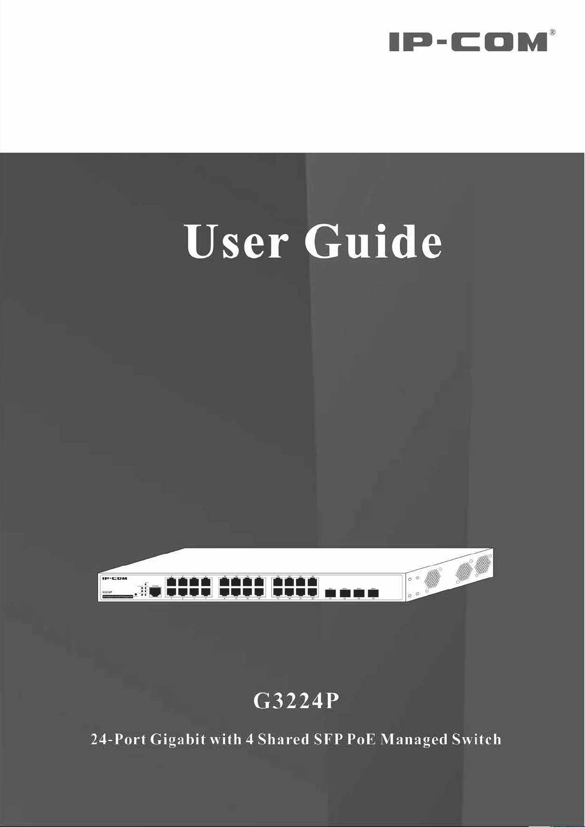
Page 2

Copyright Statement
is the registered trademark of IP-COM Networks Co., Ltd. All the products and product names
mentioned herein are the trademarks or registered trademarks of their respective holders. Copyright of the whole
product as integration, including its accessories and software, belongs to IP-COM Networks Co., Ltd. No part of
this publication can be reproduced, transmitted, transcribed, stored in a retrieval system, or translated into any
language in any form or by any means without the prior written permission of IP-COM Networks Co., Ltd. If you
would like to know more about our product information, please visit our website at www.ip-com.com.cn.
Disclaimer
Pictures, images and product specifications herein are for references only. To improve internal design, operational
function, and/or reliability, IP-COM reserves the right to make changes to the products described in this document
without obligation to notify any person or organization of such revisions or changes. IP-COM does not assume any
liability that may occur due to the use or application of the product or circuit layout(s) described herein. Every
effort has been made in the preparation of this document to ensure accuracy of the contents, but all statements,
information and recommendations in this document do not constitute the warranty of any kind, express or implied.
Page 3

Safety Guidelines
Observe the following safety guidelines to ensure your own personal safety and to help protect your system from
potential damage.
Basic Requirements
1. Keep the device completely dry and from fierce collision while storing, shipping and using;
2. Follow the instructions to install the switch;
3. Please contact the specified maintenance staff rather than dismantle the device on your own if any fault
happens.
Environmental Requirements
1. Temperature - Install the switch in a dry area, with ambient temperature between 0 and 40ºC (32 and 104ºF).
Keep the switch away from heat sources such as direct sunlight, warm air exhausts, hot-air vents, and heaters;
2. Operating humidity - The installation location should have a maximum relative humidity of 90%,
non-condensing;
3. Ventilation - Do not restrict airflow by covering or obstructing air inlets on the sides of the switch. Keep it at
least 10cm free on all sides for cooling. Be sure there is adequate airflow in the room or wiring closet where
the switch is installed;
4. Operating conditions - Keep the switch away from electromagnetic noise, such as photocopy machines,
microwaves, cellphones, etc.
Use Notes
1. Use the provided accessories, such as the cable, mounting kit, etc.
2. Ensure the basic supply voltage standard is met;
3. Keep the power plug clean and dry in case electric shock or other dangers;
4. Keep your hands dry while cabling;
5. Shut down the device and power it off before unplugging the switch;
6. In a lightning day, disconnect the power supply and unplug all cables, such as the power cord, fiber, Ethernet
cable, etc.
7. Disconnect the power supply and pull out the plug if the device will be out of use for a long time;
8. Keep the device far from water or other liquids;
9. Contact the technical staff if any problem occurs;
10. Do not tread on, drag or excessively bend the cable;
11. Do not use worn or aged cables;
12. Do not look the fiber interface in your eyes in case of eye damage;
13. Prevent some matters, such as metal chips, from entering the device through the ventilation hole;
14. Do not scrape or fray the device’s housing shell, in case abnormal operation or human body allergic reaction;
15. Keep the device out of children’s reach.
i
Page 4

Cleaning Notes
1. Shut down the device and pull out all cables before cleaning it;
2. Use soft cloth to clean the device’s housing shell.
Environmental Protection
1. Throw the discarded device or batteries into the specified recycling places;
2. Observe the local processing acts about relevant packages, wasted batteries and discarded device, and support
recycling.
ii
Page 5
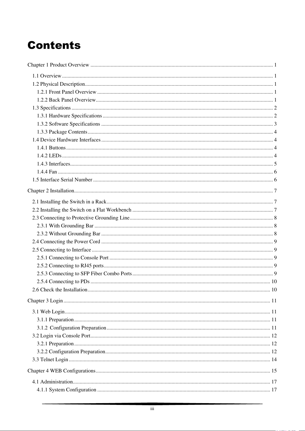
Contents
Chapter 1 Product Overview ....................................................................................................................................... 1
1.1 Overview ............................................................................................................................................................ 1
1.2 Physical Description ........................................................................................................................................... 1
1.2.1 Front Panel Overview .................................................................................................................................. 1
1.2.2 Back Panel Overview ................................................................................................................................... 1
1.3 Specifications ..................................................................................................................................................... 2
1.3.1 Hardware Specifications .............................................................................................................................. 2
1.3.2 Software Specifications ............................................................................................................................... 3
1.3.3 Package Contents ......................................................................................................................................... 4
1.4 Device Hardware Interfaces ............................................................................................................................... 4
1.4.1 Buttons ......................................................................................................................................................... 4
1.4.2 LEDs ............................................................................................................................................................ 4
1.4.3 Interfaces ...................................................................................................................................................... 5
1.4.4 Fan ............................................................................................................................................................... 6
1.5 Interface Serial Number ..................................................................................................................................... 6
Chapter 2 Installation ................................................................................................................................................... 7
2.1 Installing the Switch in a Rack ........................................................................................................................... 7
2.2 Installing the Switch on a Flat Workbench ........................................................................................................ 7
2.3 Connecting to Protective Grounding Line .......................................................................................................... 8
2.3.1 With Grounding Bar .................................................................................................................................... 8
2.3.2 Without Grounding Bar ............................................................................................................................... 8
2.4 Connecting the Power Cord ............................................................................................................................... 9
2.5 Connecting to Interface ...................................................................................................................................... 9
2.5.1 Connecting to Console Port ......................................................................................................................... 9
2.5.2 Connecting to RJ45 ports ............................................................................................................................. 9
2.5.3 Connecting to SFP Fiber Combo Ports ........................................................................................................ 9
2.5.4 Connecting to PDs ..................................................................................................................................... 10
2.6 Check the Installation ....................................................................................................................................... 10
Chapter 3 Login ......................................................................................................................................................... 11
3.1 Web Login ........................................................................................................................................................ 11
3.1.1 Preparation ................................................................................................................................................. 11
3.1.2 Configuration Preparation ......................................................................................................................... 11
3.2 Login via Console Port ..................................................................................................................................... 12
3.2.1 Preparation ................................................................................................................................................. 12
3.2.2 Configuration Preparation .......................................................................................................................... 12
3.3 Telnet Login ..................................................................................................................................................... 14
Chapter 4 WEB Configurations ................................................................................................................................. 15
4.1 Administration .................................................................................................................................................. 17
4.1.1 System Configuration ................................................................................................................................ 17
iii
Page 6
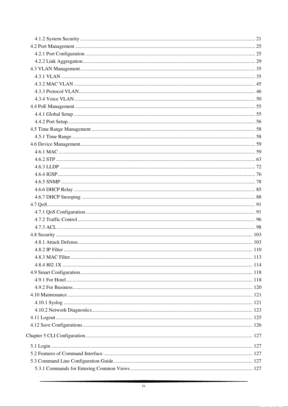
4.1.2 System Security ......................................................................................................................................... 21
4.2 Port Management ............................................................................................................................................. 25
4.2.1 Port Configuration ..................................................................................................................................... 25
4.2.2 Link Aggregation ....................................................................................................................................... 29
4.3 VLAN Management ......................................................................................................................................... 35
4.3.1 VLAN ........................................................................................................................................................ 35
4.3.2 MAC VLAN .............................................................................................................................................. 45
4.3.3 Protocol VLAN .......................................................................................................................................... 46
4.3.4 Voice VLAN .............................................................................................................................................. 50
4.4 PoE Management ............................................................................................................................................. 55
4.4.1 Global Setup .............................................................................................................................................. 55
4.4.2 Port Setup ................................................................................................................................................... 56
4.5 Time Range Management ................................................................................................................................ 58
4.5.1 Time Range ................................................................................................................................................ 58
4.6 Device Management ......................................................................................................................................... 59
4.6.1 MAC .......................................................................................................................................................... 59
4.6.2 STP ............................................................................................................................................................ 63
4.6.3 LLDP ......................................................................................................................................................... 72
4.6.4 IGSP ........................................................................................................................................................... 76
4.6.5 SNMP ........................................................................................................................................................ 78
4.6.6 DHCP Relay .............................................................................................................................................. 85
4.6.7 DHCP Snooping ........................................................................................................................................ 88
4.7 QoS ................................................................................................................................................................... 91
4.7.1 QoS Configuration ..................................................................................................................................... 91
4.7.2 Traffic Control ........................................................................................................................................... 96
4.7.3 ACL ........................................................................................................................................................... 98
4.8 Security .......................................................................................................................................................... 103
4.8.1 Attack Defense ......................................................................................................................................... 103
4.8.2 IP Filter .................................................................................................................................................... 110
4.8.3 MAC Filter ............................................................................................................................................... 113
4.8.4 802.1X ..................................................................................................................................................... 114
4.9 Smart Configuration ....................................................................................................................................... 118
4.9.1 For Hotel .................................................................................................................................................. 118
4.9.2 For Business ............................................................................................................................................. 120
4.10 Maintenance ................................................................................................................................................. 121
4.10.1 Syslog .................................................................................................................................................... 121
4.10.2 Network Diagnostics .............................................................................................................................. 123
4.11 Logout .......................................................................................................................................................... 125
4.12 Save Configurations ..................................................................................................................................... 126
Chapter 5 CLI Configuration ................................................................................................................................... 127
5.1 Login .............................................................................................................................................................. 127
5.2 Features of Command Interface ..................................................................................................................... 127
5.3 Command Line Configuration Guide ............................................................................................................. 127
5.3.1 Commands for Entering Common Views ................................................................................................ 127
iv
Page 7
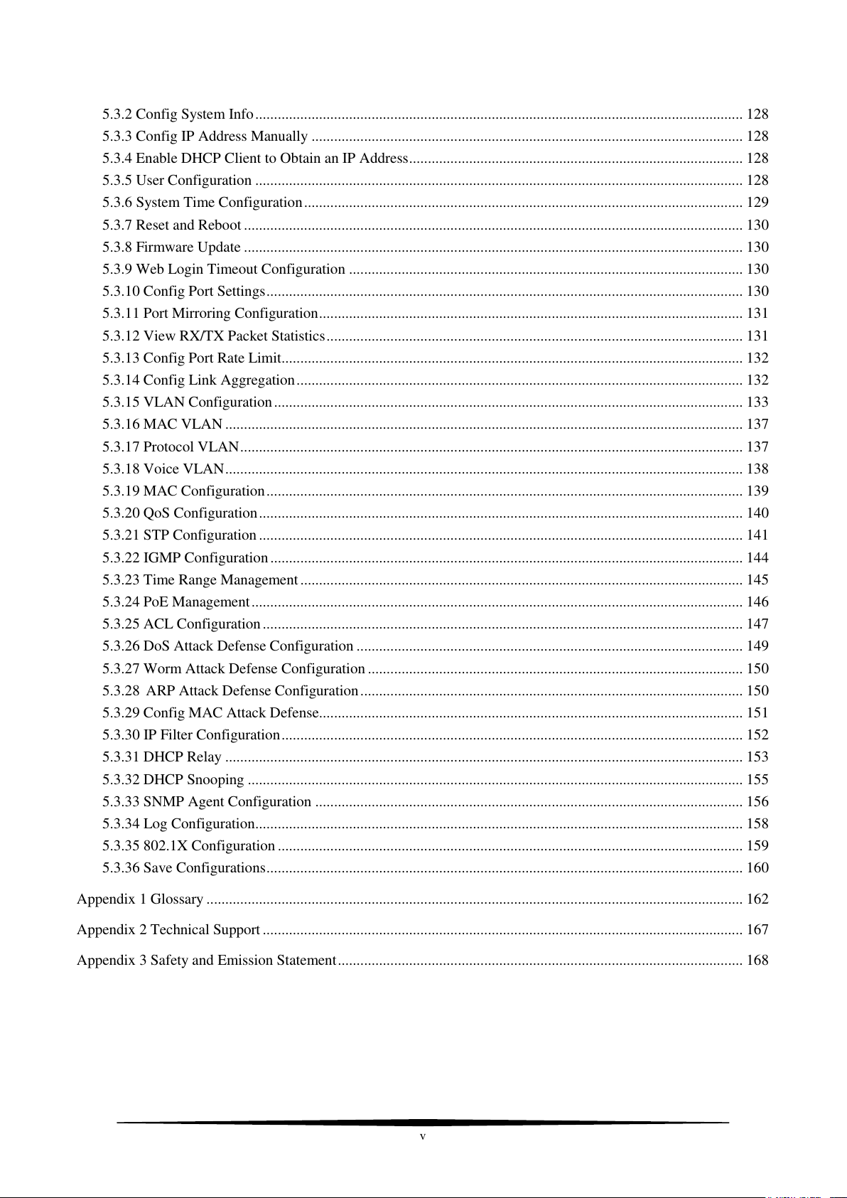
5.3.2 Config System Info .................................................................................................................................. 128
5.3.3 Config IP Address Manually ................................................................................................................... 128
5.3.4 Enable DHCP Client to Obtain an IP Address ......................................................................................... 128
5.3.5 User Configuration .................................................................................................................................. 128
5.3.6 System Time Configuration ..................................................................................................................... 129
5.3.7 Reset and Reboot ..................................................................................................................................... 130
5.3.8 Firmware Update ..................................................................................................................................... 130
5.3.9 Web Login Timeout Configuration ......................................................................................................... 130
5.3.10 Config Port Settings ............................................................................................................................... 130
5.3.11 Port Mirroring Configuration ................................................................................................................. 131
5.3.12 View RX/TX Packet Statistics ............................................................................................................... 131
5.3.13 Config Port Rate Limit........................................................................................................................... 132
5.3.14 Config Link Aggregation ....................................................................................................................... 132
5.3.15 VLAN Configuration ............................................................................................................................. 133
5.3.16 MAC VLAN .......................................................................................................................................... 137
5.3.17 Protocol VLAN ...................................................................................................................................... 137
5.3.18 Voice VLAN .......................................................................................................................................... 138
5.3.19 MAC Configuration ............................................................................................................................... 139
5.3.20 QoS Configuration ................................................................................................................................. 140
5.3.21 STP Configuration ................................................................................................................................. 141
5.3.22 IGMP Configuration .............................................................................................................................. 144
5.3.23 Time Range Management ...................................................................................................................... 145
5.3.24 PoE Management ................................................................................................................................... 146
5.3.25 ACL Configuration ................................................................................................................................ 147
5.3.26 DoS Attack Defense Configuration ....................................................................................................... 149
5.3.27 Worm Attack Defense Configuration .................................................................................................... 150
5.3.28 ARP Attack Defense Configuration ...................................................................................................... 150
5.3.29 Config MAC Attack Defense ................................................................................................................. 151
5.3.30 IP Filter Configuration ........................................................................................................................... 152
5.3.31 DHCP Relay .......................................................................................................................................... 153
5.3.32 DHCP Snooping .................................................................................................................................... 155
5.3.33 SNMP Agent Configuration .................................................................................................................. 156
5.3.34 Log Configuration .................................................................................................................................. 158
5.3.35 802.1X Configuration ............................................................................................................................ 159
5.3.36 Save Configurations ............................................................................................................................... 160
Appendix 1 Glossary ............................................................................................................................................... 162
Appendix 2 Technical Support ................................................................................................................................ 167
Appendix 3 Safety and Emission Statement ............................................................................................................ 168
v
Page 8
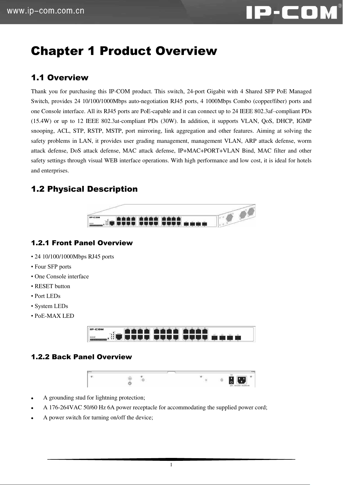
Chapter 1 Product Overview
1.1 Overview
Thank you for purchasing this IP-COM product. This switch, 24-port Gigabit with 4 Shared SFP PoE Managed
Switch, provides 24 10/100/1000Mbps auto-negotiation RJ45 ports, 4 1000Mbps Combo (copper/fiber) ports and
one Console interface. All its RJ45 ports are PoE-capable and it can connect up to 24 IEEE 802.3af–compliant PDs
(15.4W) or up to 12 IEEE 802.3at-compliant PDs (30W). In addition, it supports VLAN, QoS, DHCP, IGMP
snooping, ACL, STP, RSTP, MSTP, port mirroring, link aggregation and other features. Aiming at solving the
safety problems in LAN, it provides user grading management, management VLAN, ARP attack defense, worm
attack defense, DoS attack defense, MAC attack defense, IP+MAC+PORT+VLAN Bind, MAC filter and other
safety settings through visual WEB interface operations. With high performance and low cost, it is ideal for hotels
and enterprises.
1.2 Physical Description
1.2.1 Front Panel Overview
• 24 10/100/1000Mbps RJ45 ports
• Four SFP ports
• One Console interface
• RESET button
• Port LEDs
• System LEDs
• PoE-MAX LED
1.2.2 Back Panel Overview
A grounding stud for lightning protection;
A 176-264VAC 50/60 Hz 6A power receptacle for accommodating the supplied power cord;
A power switch for turning on/off the device;
1
Page 9
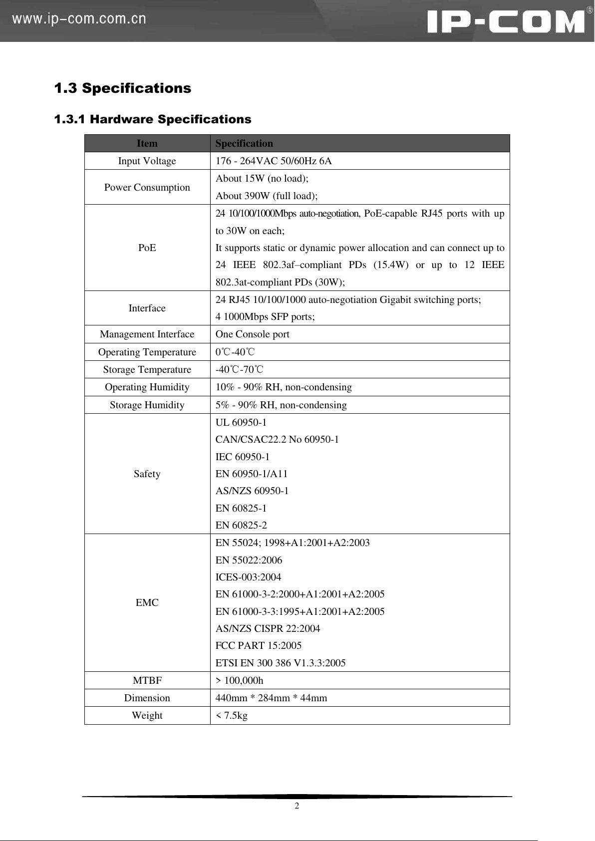
1.3 Specifications
Item
Specification
Input Voltage
176 - 264VAC 50/60Hz 6A
Power Consumption
About 15W (no load);
About 390W (full load);
PoE
24 10/100/1000Mbps auto-negotiation, PoE-capable RJ45 ports with up
to 30W on each;
It supports static or dynamic power allocation and can connect up to
24 IEEE 802.3af–compliant PDs (15.4W) or up to 12 IEEE
802.3at-compliant PDs (30W);
Interface
24 RJ45 10/100/1000 auto-negotiation Gigabit switching ports;
4 1000Mbps SFP ports;
Management Interface
One Console port
Operating Temperature
0℃-40℃
Storage Temperature
-40℃-70℃
Operating Humidity
10% - 90% RH, non-condensing
Storage Humidity
5% - 90% RH, non-condensing
Safety
UL 60950-1
CAN/CSAC22.2 No 60950-1
IEC 60950-1
EN 60950-1/A11
AS/NZS 60950-1
EN 60825-1
EN 60825-2
EMC
EN 55024; 1998+A1:2001+A2:2003
EN 55022:2006
ICES-003:2004
EN 61000-3-2:2000+A1:2001+A2:2005
EN 61000-3-3:1995+A1:2001+A2:2005
AS/NZS CISPR 22:2004
FCC PART 15:2005
ETSI EN 300 386 V1.3.3:2005
MTBF
> 100,000h
Dimension
440mm * 284mm * 44mm
Weight
< 7.5kg
1.3.1 Hardware Specifications
2
Page 10
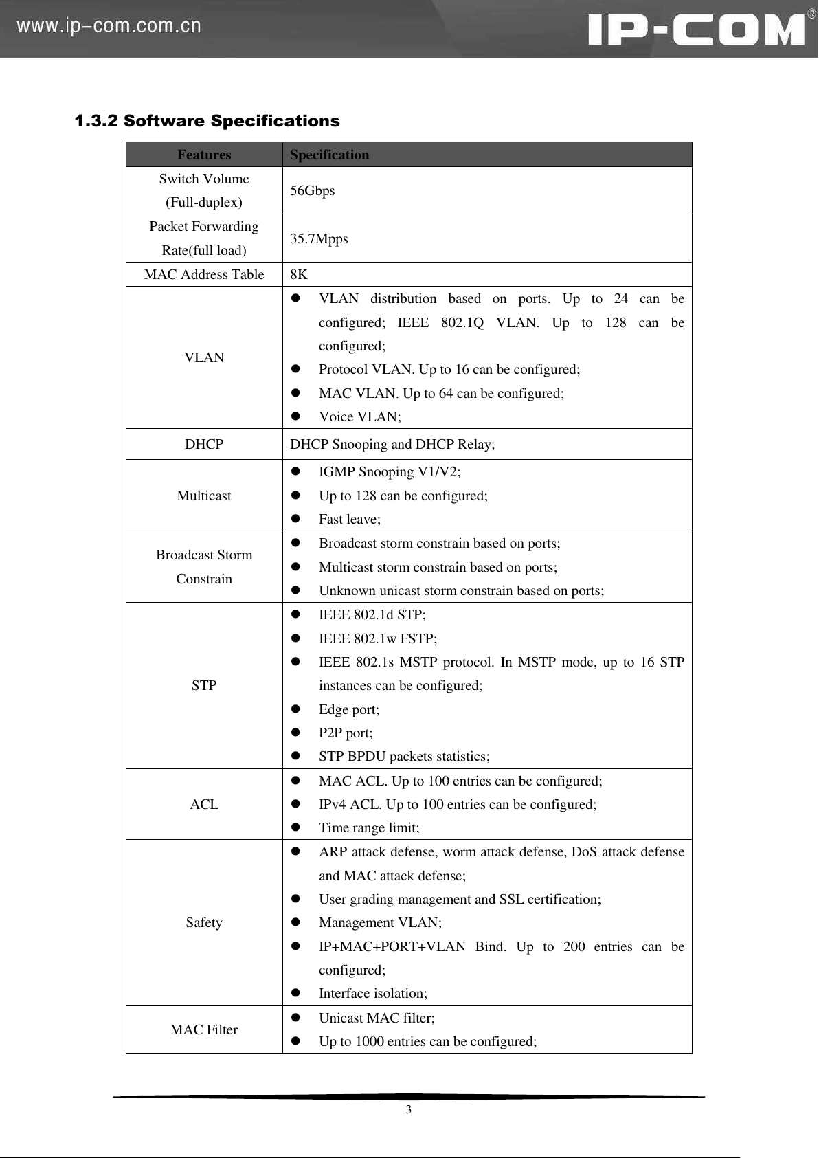
1.3.2 Software Specifications
Features
Specification
Switch Volume
(Full-duplex)
56Gbps
Packet Forwarding
Rate(full load)
35.7Mpps
MAC Address Table
8K
VLAN
VLAN distribution based on ports. Up to 24 can be
configured; IEEE 802.1Q VLAN. Up to 128 can be
configured;
Protocol VLAN. Up to 16 can be configured;
MAC VLAN. Up to 64 can be configured;
Voice VLAN;
DHCP
DHCP Snooping and DHCP Relay;
Multicast
IGMP Snooping V1/V2;
Up to 128 can be configured;
Fast leave;
Broadcast Storm
Constrain
Broadcast storm constrain based on ports;
Multicast storm constrain based on ports;
Unknown unicast storm constrain based on ports;
STP
IEEE 802.1d STP;
IEEE 802.1w FSTP;
IEEE 802.1s MSTP protocol. In MSTP mode, up to 16 STP
instances can be configured;
Edge port;
P2P port;
STP BPDU packets statistics;
ACL
MAC ACL. Up to 100 entries can be configured;
IPv4 ACL. Up to 100 entries can be configured;
Time range limit;
Safety
ARP attack defense, worm attack defense, DoS attack defense
and MAC attack defense;
User grading management and SSL certification;
Management VLAN;
IP+MAC+PORT+VLAN Bind. Up to 200 entries can be
configured;
Interface isolation;
MAC Filter
Unicast MAC filter;
Up to 1000 entries can be configured;
3
Page 11
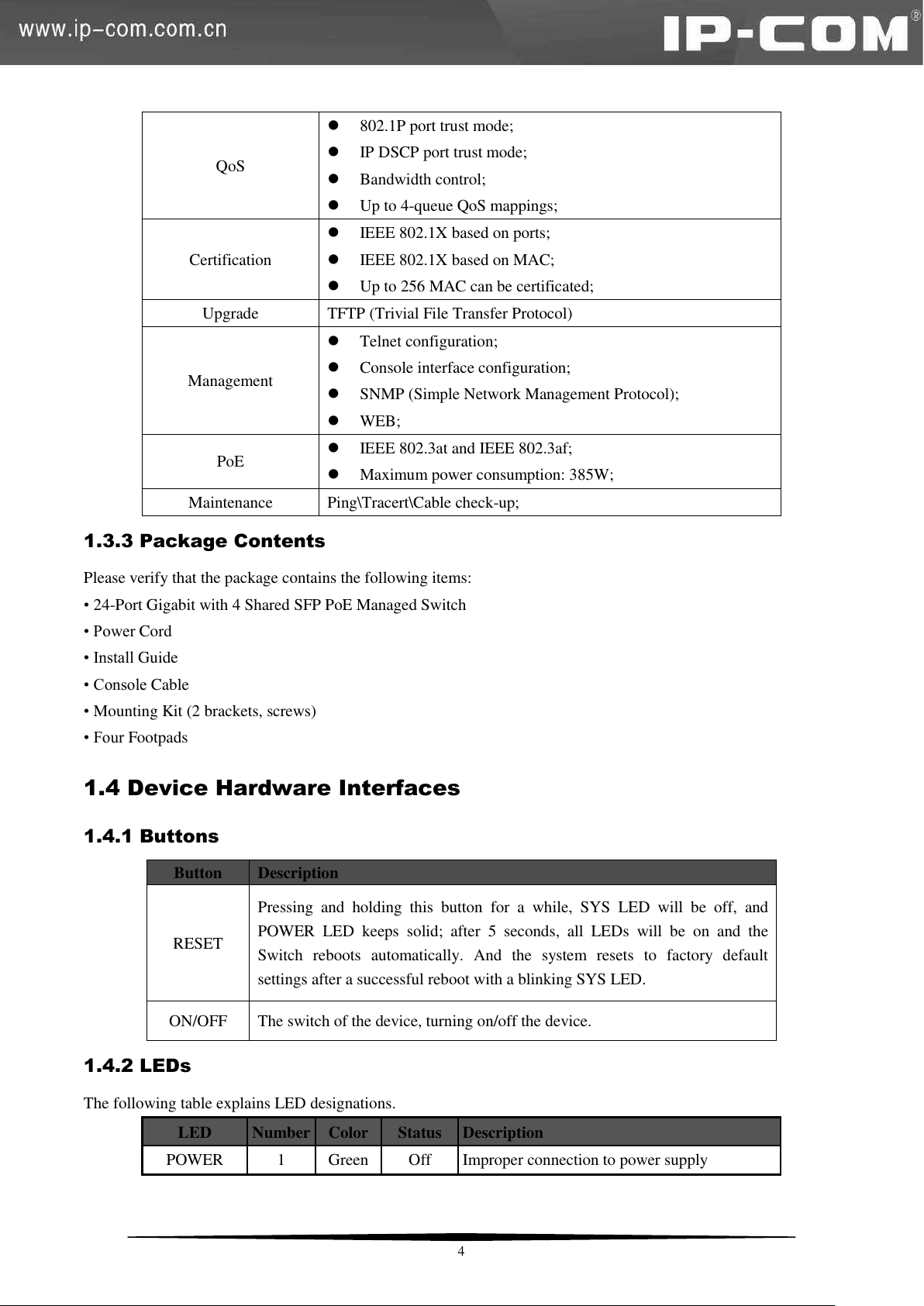
QoS
802.1P port trust mode;
IP DSCP port trust mode;
Bandwidth control;
Up to 4-queue QoS mappings;
Certification
IEEE 802.1X based on ports;
IEEE 802.1X based on MAC;
Up to 256 MAC can be certificated;
Upgrade
TFTP (Trivial File Transfer Protocol)
Management
Telnet configuration;
Console interface configuration;
SNMP (Simple Network Management Protocol);
WEB;
PoE
IEEE 802.3at and IEEE 802.3af;
Maximum power consumption: 385W;
Maintenance
Ping\Tracert\Cable check-up;
Button
Description
RESET
Pressing and holding this button for a while, SYS LED will be off, and
POWER LED keeps solid; after 5 seconds, all LEDs will be on and the
Switch reboots automatically. And the system resets to factory default
settings after a successful reboot with a blinking SYS LED.
ON/OFF
The switch of the device, turning on/off the device.
LED
Number
Color
Status
Description
POWER
1
Green
Off
Improper connection to power supply
1.3.3 Package Contents
Please verify that the package contains the following items:
• 24-Port Gigabit with 4 Shared SFP PoE Managed Switch
• Power Cord
• Install Guide
• Console Cable
• Mounting Kit (2 brackets, screws)
• Four Footpads
1.4 Device Hardware Interfaces
1.4.1 Buttons
1.4.2 LEDs
The following table explains LED designations.
4
Page 12
LED
Number
Color
Status
Description
Solid
Proper connection to power supply
SYS
1
Green
Off
System is functioning improperly.
Solid
System is functioning improperly.
Blinking
System is functioning properly.
PoE-MAX
1
Green
Off
Power available for additional PDs
Solid
Reaching max power budget (354.2W) and no
more power available for another new PD
Link/Act 1-24
24
Orange
Off
An invalid link is established.
Solid
A valid link is established.
Blinking
Transmitting packets
PoE 1-24
24
Green
Solid
The PoE powered device (PD) is connected and
the port is supplying power successfully.
Off
No PoE-powered device (PD) connected
SFP1-SFP4
4
Green
Solid
Packet transmission or a valid link is
established on the port.
Off
An invalid link is established on the port.
Speed
Working Mode
10Mbps (auto-negotiation)
Half/Full duplex auto-negotiation
100Mbps (auto-negotiation)
Half/Full duplex auto-negotiation
1000Mbps (auto-negotiation)
Full duplex auto-negotiation
1.4.3 Interfaces
1.4.3.1 Console Interface
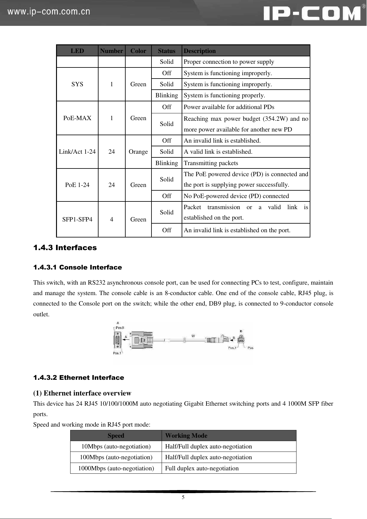
This switch, with an RS232 asynchronous console port, can be used for connecting PCs to test, configure, maintain
and manage the system. The console cable is an 8-conductor cable. One end of the console cable, RJ45 plug, is
connected to the Console port on the switch; while the other end, DB9 plug, is connected to 9-conductor console
outlet.
1.4.3.2 Ethernet Interface
(1) Ethernet interface overview
This device has 24 RJ45 10/100/1000M auto negotiating Gigabit Ethernet switching ports and 4 1000M SFP fiber
ports.
Speed and working mode in RJ45 port mode:
5
Page 13
Note:
SFP fiber ports can only work in full-duplex auto-negotiation mode.
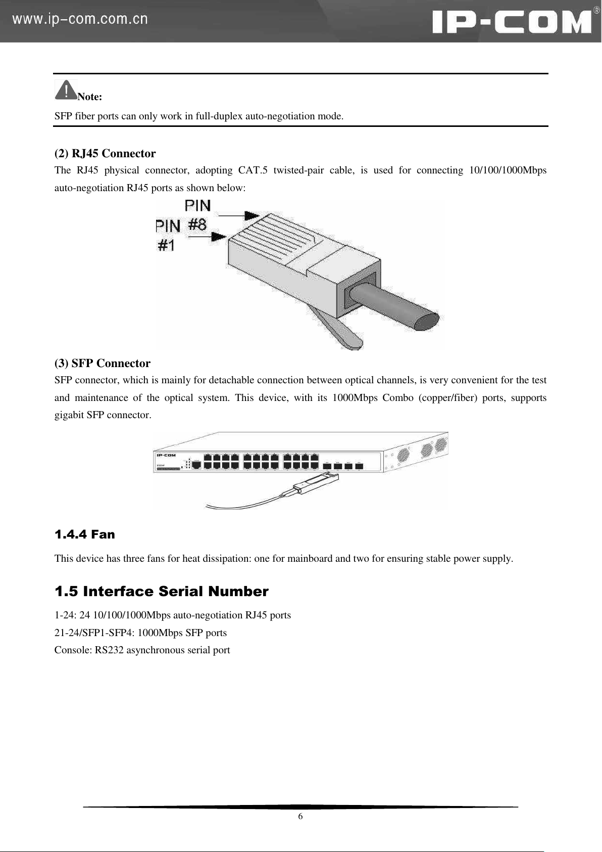
(2) RJ45 Connector
The RJ45 physical connector, adopting CAT.5 twisted-pair cable, is used for connecting 10/100/1000Mbps
auto-negotiation RJ45 ports as shown below:
(3) SFP Connector
SFP connector, which is mainly for detachable connection between optical channels, is very convenient for the test
and maintenance of the optical system. This device, with its 1000Mbps Combo (copper/fiber) ports, supports
gigabit SFP connector.
1.4.4 Fan
This device has three fans for heat dissipation: one for mainboard and two for ensuring stable power supply.
1.5 Interface Serial Number
1-24: 24 10/100/1000Mbps auto-negotiation RJ45 ports
21-24/SFP1-SFP4: 1000Mbps SFP ports
Console: RS232 asynchronous serial port
6
Page 14
Chapter 2 Installation
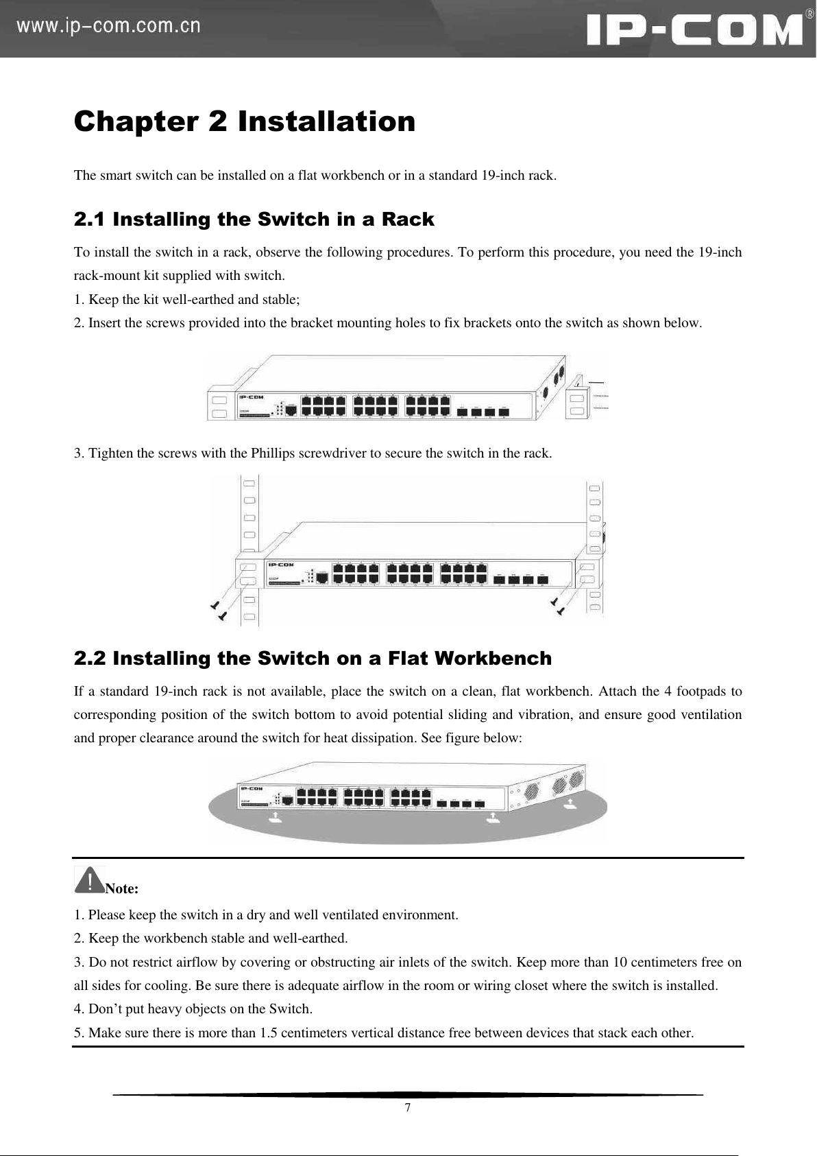
The smart switch can be installed on a flat workbench or in a standard 19-inch rack.
2.1 Installing the Switch in a Rack
To install the switch in a rack, observe the following procedures. To perform this procedure, you need the 19-inch
rack-mount kit supplied with switch.
1. Keep the kit well-earthed and stable;
2. Insert the screws provided into the bracket mounting holes to fix brackets onto the switch as shown below.
3. Tighten the screws with the Phillips screwdriver to secure the switch in the rack.
2.2 Installing the Switch on a Flat Workbench
If a standard 19-inch rack is not available, place the switch on a clean, flat workbench. Attach the 4 footpads to
corresponding position of the switch bottom to avoid potential sliding and vibration, and ensure good ventilation
and proper clearance around the switch for heat dissipation. See figure below:
Note:
1. Please keep the switch in a dry and well ventilated environment.
2. Keep the workbench stable and well-earthed.
3. Do not restrict airflow by covering or obstructing air inlets of the switch. Keep more than 10 centimeters free on
all sides for cooling. Be sure there is adequate airflow in the room or wiring closet where the switch is installed.
4. Don’t put heavy objects on the Switch.
5. Make sure there is more than 1.5 centimeters vertical distance free between devices that stack each other.
7
Page 15
2.3 Connecting to Protective Grounding Line
Proper connection of protective grounding line is important for lightning protection and anti-interference. Proper
connection is as follows:
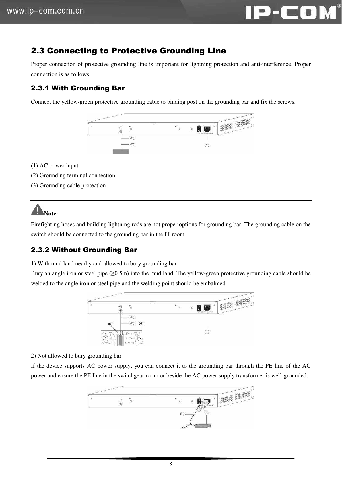
2.3.1 With Grounding Bar
Connect the yellow-green protective grounding cable to binding post on the grounding bar and fix the screws.
(1) AC power input
(2) Grounding terminal connection
(3) Grounding cable protection
Note:
Firefighting hoses and building lightning rods are not proper options for grounding bar. The grounding cable on the
switch should be connected to the grounding bar in the IT room.
2.3.2 Without Grounding Bar
1) With mud land nearby and allowed to bury grounding bar
Bury an angle iron or steel pipe (≥0.5m) into the mud land. The yellow-green protective grounding cable should be
welded to the angle iron or steel pipe and the welding point should be embalmed.
2) Not allowed to bury grounding bar
If the device supports AC power supply, you can connect it to the grounding bar through the PE line of the AC
power and ensure the PE line in the switchgear room or beside the AC power supply transformer is well-grounded.
8
Page 16
2.4 Connecting the Power Cord
Step1: Connect one end of the included power cord to the switch and the other end to a nearby AC power outlet.
Step2: Verify the power LED on switch's front panel. An illuminated light indicates a proper power connection.
Note:
As for the power cord, different countries have different standards. Please determine whether to install the card slot
to fix the power cord according to the actual situation.
2.5 Connecting to Interface
2.5.1 Connecting to Console Port
Follow below steps to connect a PC or terminal to the switch (The terminal can be the emulation program with
RS232 console or a PC. Here take the PC for example):
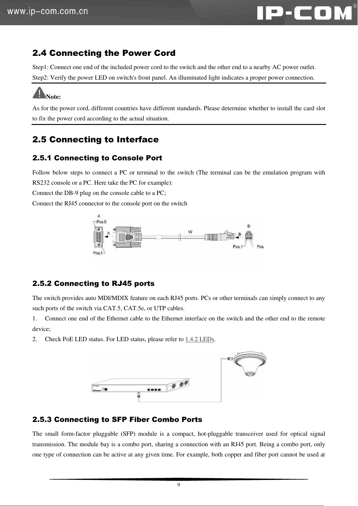
Connect the DB-9 plug on the console cable to a PC;
Connect the RJ45 connector to the console port on the switch
2.5.2 Connecting to RJ45 ports
The switch provides auto MDI/MDIX feature on each RJ45 ports. PCs or other terminals can simply connect to any
such ports of the switch via CAT.5, CAT.5e, or UTP cables.
1. Connect one end of the Ethernet cable to the Ethernet interface on the switch and the other end to the remote
device;
2. Check PoE LED status. For LED status, please refer to 1.4.2 LEDs.
2.5.3 Connecting to SFP Fiber Combo Ports
The small form-factor pluggable (SFP) module is a compact, hot-pluggable transceiver used for optical signal
transmission. The module bay is a combo port, sharing a connection with an RJ45 port. Being a combo port, only
one type of connection can be active at any given time. For example, both copper and fiber port cannot be used at
9
Page 17
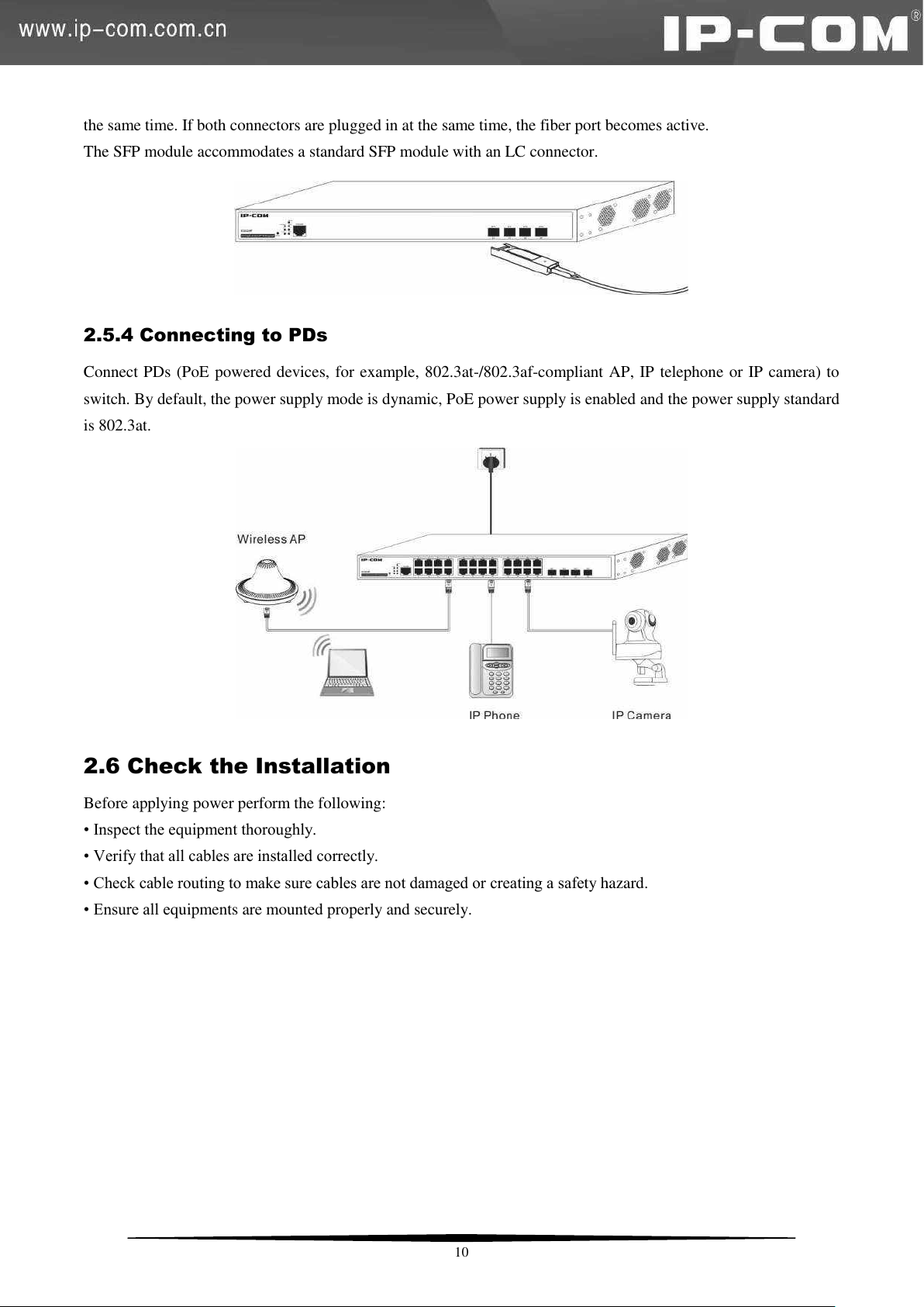
the same time. If both connectors are plugged in at the same time, the fiber port becomes active.
The SFP module accommodates a standard SFP module with an LC connector.
2.5.4 Connecting to PDs
Connect PDs (PoE powered devices, for example, 802.3at-/802.3af-compliant AP, IP telephone or IP camera) to
switch. By default, the power supply mode is dynamic, PoE power supply is enabled and the power supply standard
is 802.3at.
2.6 Check the Installation
Before applying power perform the following:
• Inspect the equipment thoroughly.
• Verify that all cables are installed correctly.
• Check cable routing to make sure cables are not damaged or creating a safety hazard.
• Ensure all equipments are mounted properly and securely.
10
Page 18
Chapter 3 Login
Item
Description
PC
Installed with a network Interface card
IP and Subnet Mask
The IP address of your PC and the switch should be in the same
network segment (It can’t be 192.168.0.1).
Web Browser
Microsoft IE 8.0 or higher
Ethernet Cable
One CAT.5 RJ45 cable
3.1 Web Login
3.1.1 Preparation
3.1.2 Configuration Preparation
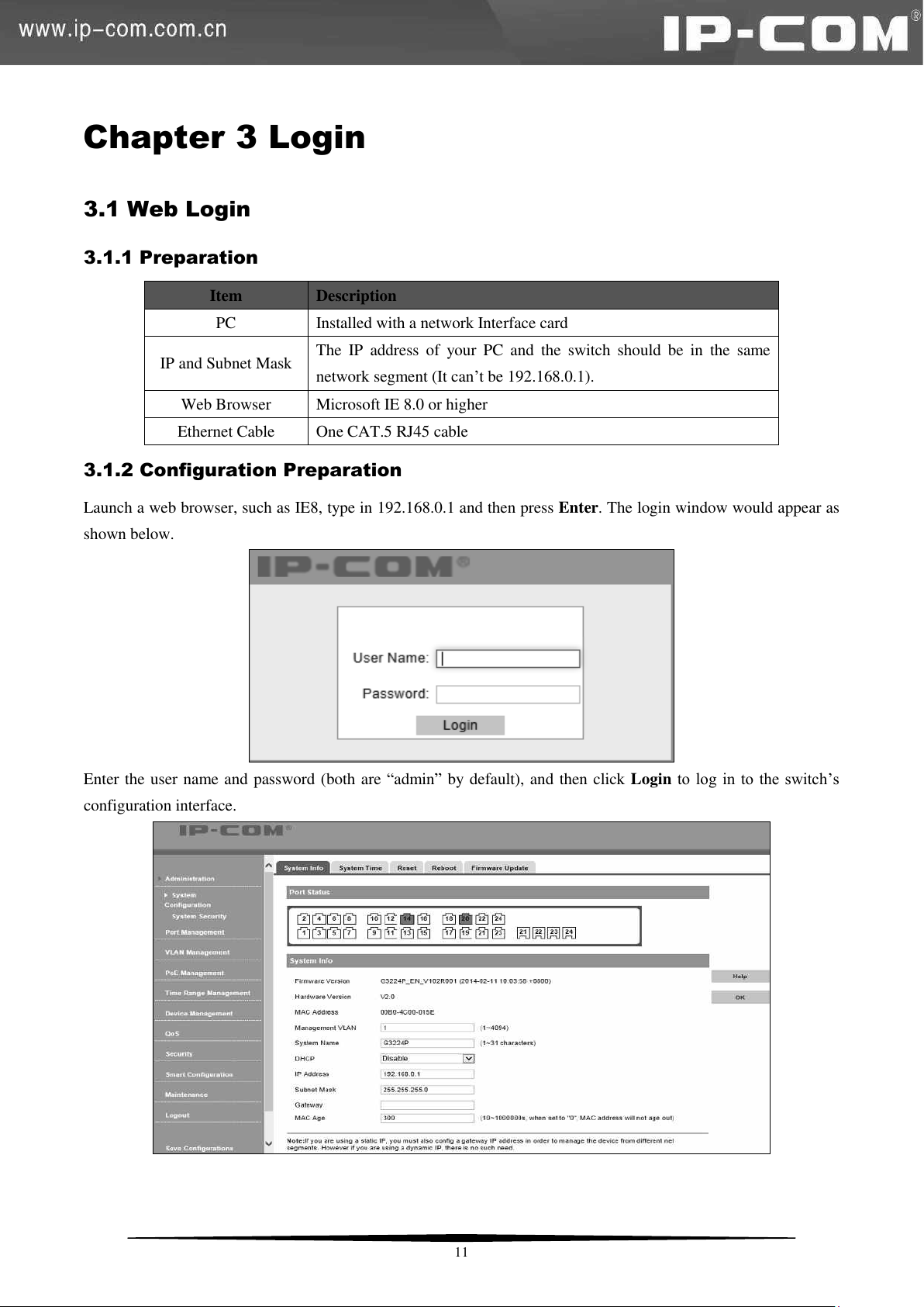
Launch a web browser, such as IE8, type in 192.168.0.1 and then press Enter. The login window would appear as
shown below.
Enter the user name and password (both are ―admin‖ by default), and then click Login to log in to the switch’s
configuration interface.
11
Page 19
Item
Description
PC
With a Console port
Ethernet Cable
DB9-RJ45 Console Cable
3.2 Login via Console Port
3.2.1 Preparation
3.2.2 Configuration Preparation
Step 1: Connect a terminal (PC) to the console port on the switch.
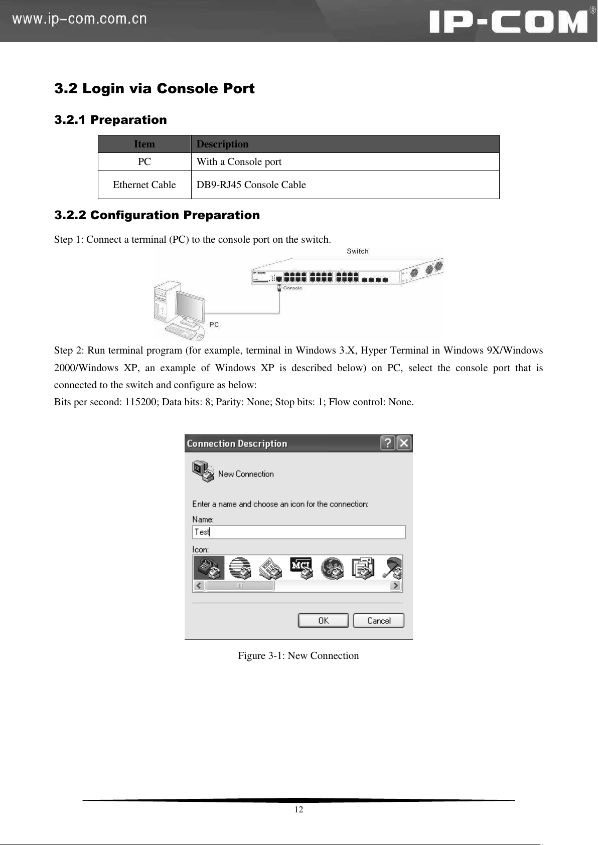
Step 2: Run terminal program (for example, terminal in Windows 3.X, Hyper Terminal in Windows 9X/Windows
2000/Windows XP, an example of Windows XP is described below) on PC, select the console port that is
connected to the switch and configure as below:
Bits per second: 115200; Data bits: 8; Parity: None; Stop bits: 1; Flow control: None.
Figure 3-1: New Connection
12
Page 20
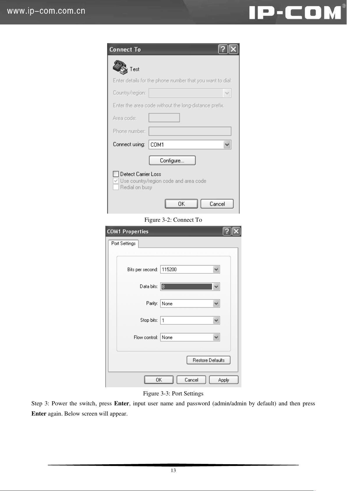
Figure 3-2: Connect To
Figure 3-3: Port Settings
Step 3: Power the switch, press Enter, input user name and password (admin/admin by default) and then press
Enter again. Below screen will appear.
13
Page 21
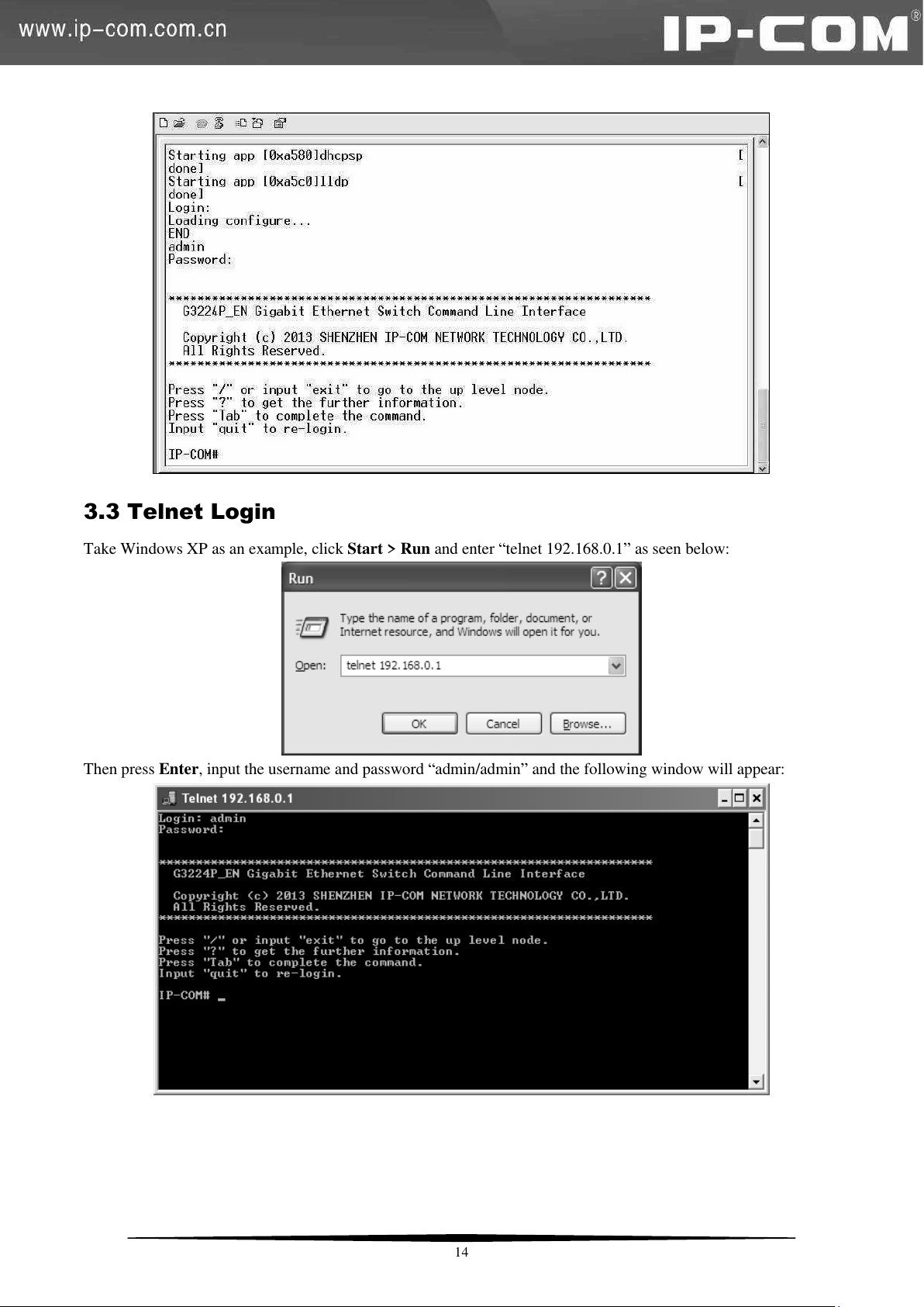
3.3 Telnet Login
Take Windows XP as an example, click Start > Run and enter ―telnet 192.168.0.1‖ as seen below:
Then press Enter, input the username and password ―admin/admin‖ and the following window will appear:
14
Page 22
Menu
Submenu
Description
System
Configuration
System Info
This section displays the device’s system parameters.
System Time
This section allows you to configure system time either by
synchronizing with SNTP server or specifying it manually.
Reset
Resets all settings to factory defaults.
Reboot
Configurations will be lost if you don’t save them before
rebooting.
Firmware Update
Update firmware.
System Security
SSL Setup
Allows you to encrypt information.
User
This section allows you to add new users and change
password.
Port Management
Port
Configuration
Allows users to configure them a port and displays port status
and statistics.
Link Aggregation
Displays static and LACP link aggregation settings and allows
users to configure them.
VLAN Management
VLAN
Allows users to configure port VLAN and 802.1Q VLAN
settings.
MAC VALN
Allows users to configure MAC VLAN and MAC VLAN
settings. Up to 64 MAC VLANs can be configured.
Protocol VLAN
Three forms: Ethernet, LLC, and SNAP. Up to 16 protocol
VLANs can be configured.
Voice VLAN
Allows users to configure voice VLAN (manual or auto).
PoE Management
Global Setup
Static and dynamic allocations are supported. The default is
dynamic allocation.
Port Setup
Two power supply standards: 802.3at and 802.3af. By default,
it is 802.3at.
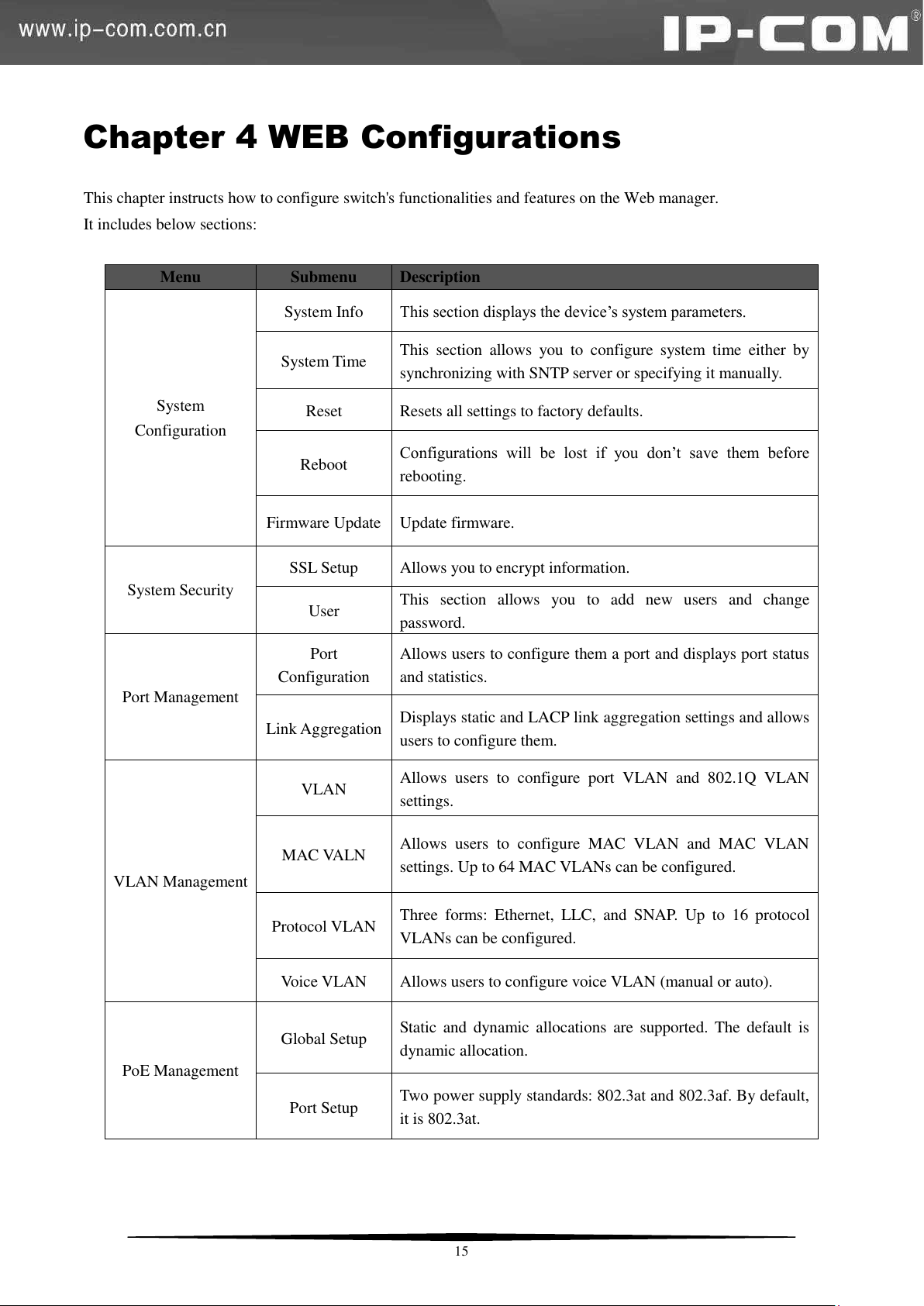
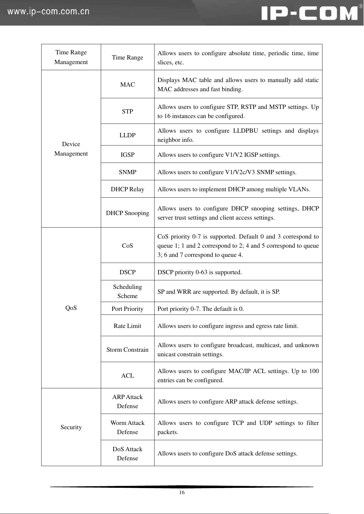
Chapter 4 WEB Configurations
This chapter instructs how to configure switch's functionalities and features on the Web manager.
It includes below sections:
15
Page 23
Time Range
Management
Time Range
Allows users to configure absolute time, periodic time, time
slices, etc.
Device
Management
MAC
Displays MAC table and allows users to manually add static
MAC addresses and fast binding.
STP
Allows users to configure STP, RSTP and MSTP settings. Up
to 16 instances can be configured.
LLDP
Allows users to configure LLDPBU settings and displays
neighbor info.
IGSP
Allows users to configure V1/V2 IGSP settings.
SNMP
Allows users to configure V1/V2c/V3 SNMP settings.
DHCP Relay
Allows users to implement DHCP among multiple VLANs.
DHCP Snooping
Allows users to configure DHCP snooping settings, DHCP
server trust settings and client access settings.
QoS
CoS
CoS priority 0-7 is supported. Default 0 and 3 correspond to
queue 1; 1 and 2 correspond to 2; 4 and 5 correspond to queue
3; 6 and 7 correspond to queue 4.
DSCP
DSCP priority 0-63 is supported.
Scheduling
Scheme
SP and WRR are supported. By default, it is SP.
Port Priority
Port priority 0-7. The default is 0.
Rate Limit
Allows users to configure ingress and egress rate limit.
Storm Constrain
Allows users to configure broadcast, multicast, and unknown
unicast constrain settings.
ACL
Allows users to configure MAC/IP ACL settings. Up to 100
entries can be configured.
Security
ARP Attack
Defense
Allows users to configure ARP attack defense settings.
Worm Attack
Defense
Allows users to configure TCP and UDP settings to filter
packets.
DoS Attack
Defense
Allows users to configure DoS attack defense settings.
16
Page 24
MAC Attack
Defense
Allows users to configure MAC attack defense settings.
IP Filter
Configure IP+MAC+Port+VLAN Binding, ARP filter and IP
filter settings.
802.1X
Displays and allows you to configure 802.1X settings.
Smart Configuration
Corporate and hotel network administrators can use this
section to easily configure file server port and router port. For
details, please refer to 4.9 Smart Configuration.
Maintenance
Allows users to configure syslog settings and network
diagnose settings.
Save Configurations
Save/backup/restore settings.
4.1 Administration
4.1.1 System Configuration
System Info
Click System Configuration > System Info to enter interface below:
17
Page 25
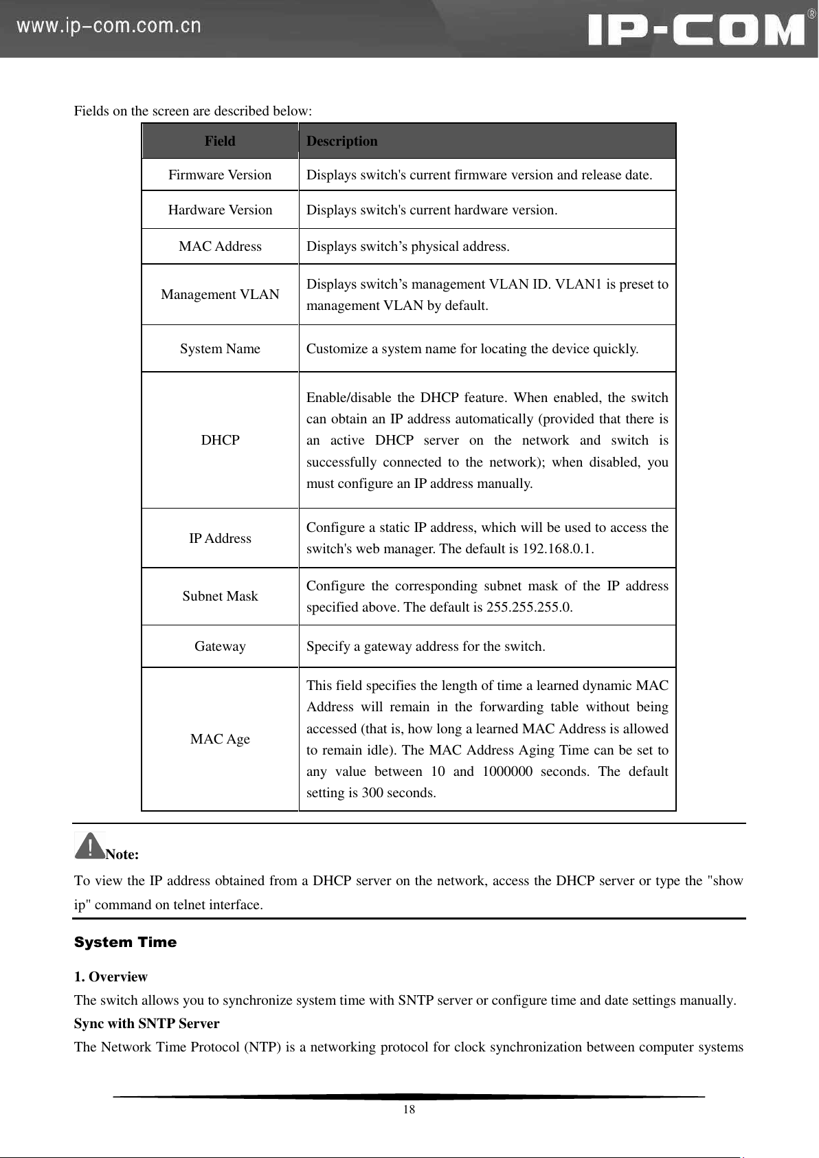
Fields on the screen are described below:
Field
Description
Firmware Version
Displays switch's current firmware version and release date.
Hardware Version
Displays switch's current hardware version.
MAC Address
Displays switch’s physical address.
Management VLAN
Displays switch’s management VLAN ID. VLAN1 is preset to
management VLAN by default.
System Name
Customize a system name for locating the device quickly.
DHCP
Enable/disable the DHCP feature. When enabled, the switch
can obtain an IP address automatically (provided that there is
an active DHCP server on the network and switch is
successfully connected to the network); when disabled, you
must configure an IP address manually.
IP Address
Configure a static IP address, which will be used to access the
switch's web manager. The default is 192.168.0.1.
Subnet Mask
Configure the corresponding subnet mask of the IP address
specified above. The default is 255.255.255.0.
Gateway
Specify a gateway address for the switch.
MAC Age
This field specifies the length of time a learned dynamic MAC
Address will remain in the forwarding table without being
accessed (that is, how long a learned MAC Address is allowed
to remain idle). The MAC Address Aging Time can be set to
any value between 10 and 1000000 seconds. The default
setting is 300 seconds.
Note:
To view the IP address obtained from a DHCP server on the network, access the DHCP server or type the "show
ip" command on telnet interface.
System Time
1. Overview
The switch allows you to synchronize system time with SNTP server or configure time and date settings manually.
Sync with SNTP Server
The Network Time Protocol (NTP) is a networking protocol for clock synchronization between computer systems
18
Page 26
over packet-switched, variable-latency data networks. Simple Network Time Protocol (SNTP) is another less
complex implementation of NTP. It synchronizes timekeeping between time servers and clients so that
clock-dependent devices on the network can consistently provide diverse time based applications. Both SNTP
server and client run over the User Datagram Protocol (UDP) on port 123. When BLAT UDP attack defense is
enabled, it won’t be unable to acquire system time automatically.
Config time and date settings manually
Manually configured time will not be updated or synchronized with other devices and will be restored to factory
defaults after system reboot.
2. System Time -- Config
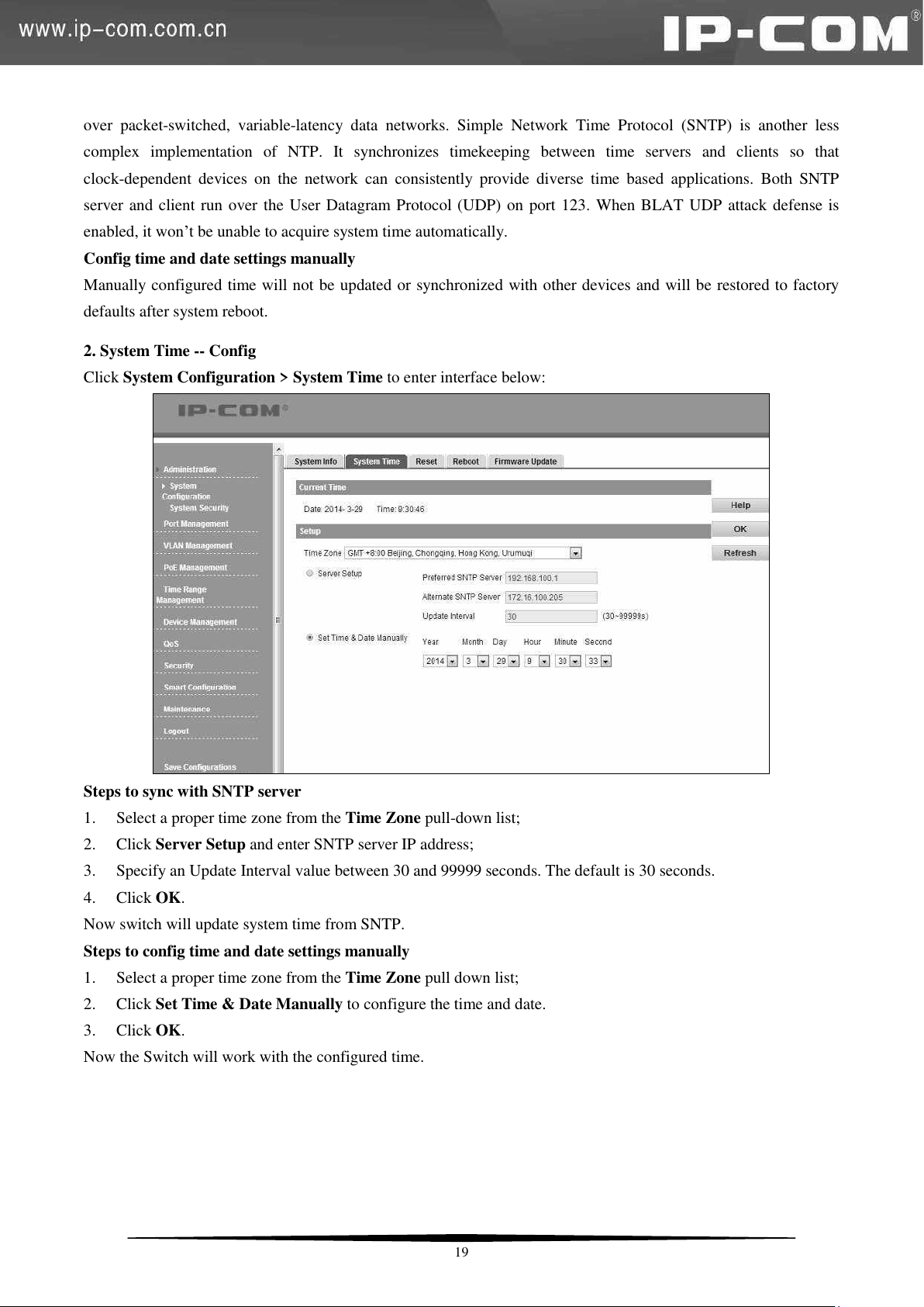
Click System Configuration > System Time to enter interface below:
Steps to sync with SNTP server
1. Select a proper time zone from the Time Zone pull-down list;
2. Click Server Setup and enter SNTP server IP address;
3. Specify an Update Interval value between 30 and 99999 seconds. The default is 30 seconds.
4. Click OK.
Now switch will update system time from SNTP.
Steps to config time and date settings manually
1. Select a proper time zone from the Time Zone pull down list;
2. Click Set Time & Date Manually to configure the time and date.
3. Click OK.
Now the Switch will work with the configured time.
19
Page 27
Reset
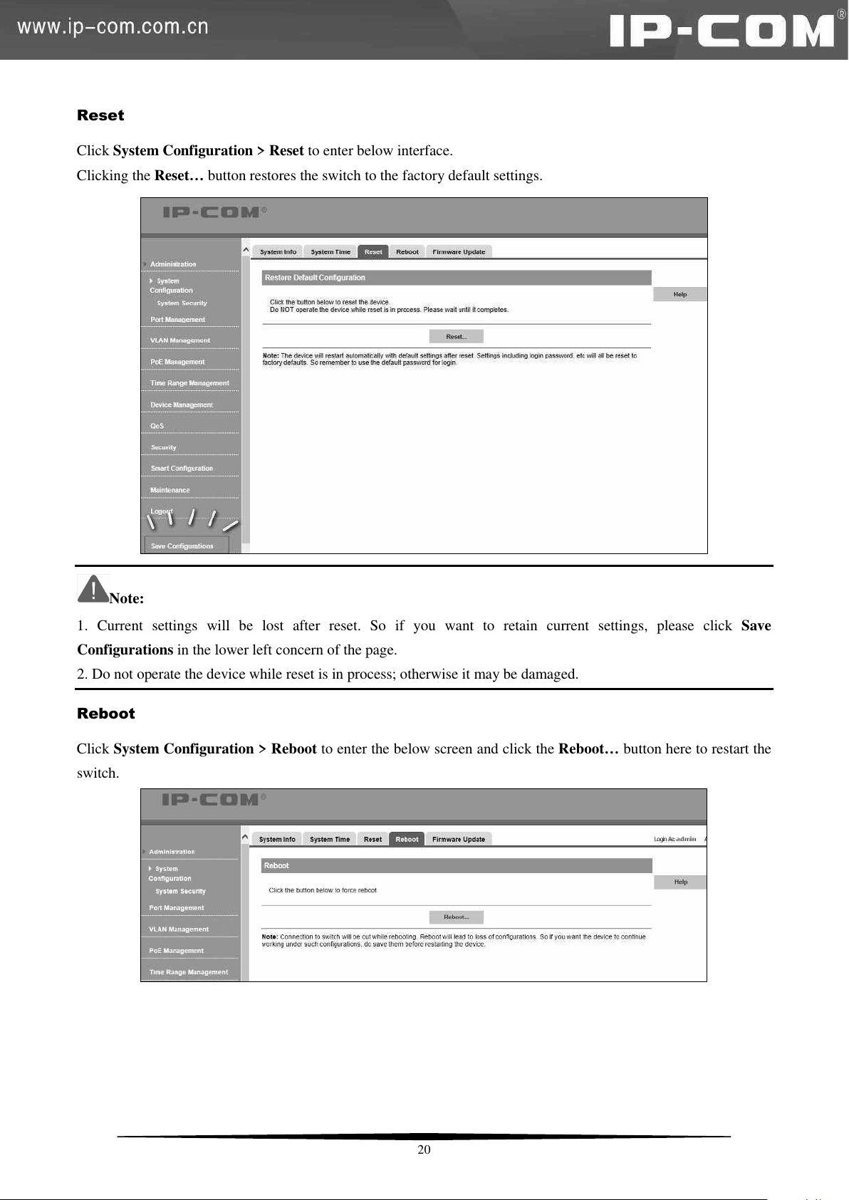
Click System Configuration > Reset to enter below interface.
Clicking the Reset… button restores the switch to the factory default settings.
Note:
1. Current settings will be lost after reset. So if you want to retain current settings, please click Save
Configurations in the lower left concern of the page.
2. Do not operate the device while reset is in process; otherwise it may be damaged.
Reboot
Click System Configuration > Reboot to enter the below screen and click the Reboot… button here to restart the
switch.
20
Page 28
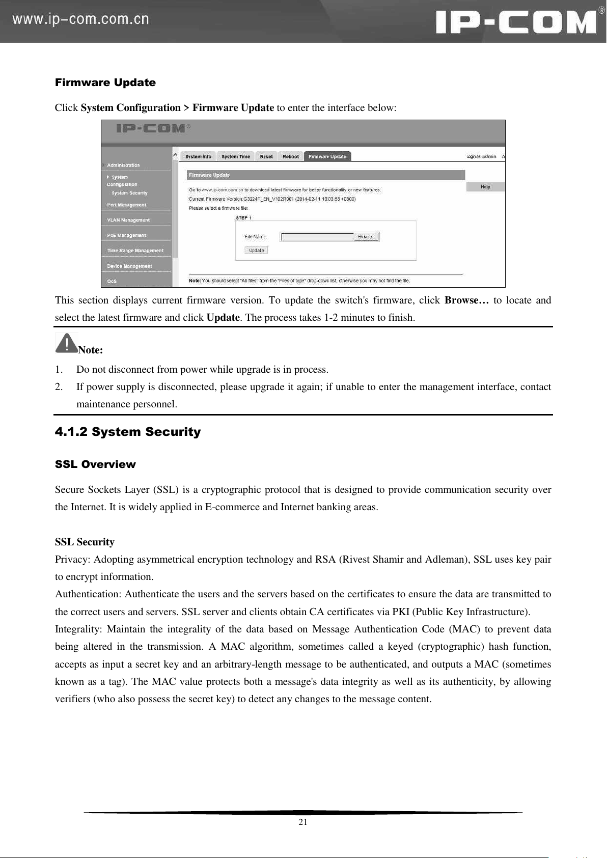
Firmware Update
Click System Configuration > Firmware Update to enter the interface below:
This section displays current firmware version. To update the switch's firmware, click Browse… to locate and
select the latest firmware and click Update. The process takes 1-2 minutes to finish.
Note:
1. Do not disconnect from power while upgrade is in process.
2. If power supply is disconnected, please upgrade it again; if unable to enter the management interface, contact
maintenance personnel.
4.1.2 System Security
SSL Overview
Secure Sockets Layer (SSL) is a cryptographic protocol that is designed to provide communication security over
the Internet. It is widely applied in E-commerce and Internet banking areas.
SSL Security
Privacy: Adopting asymmetrical encryption technology and RSA (Rivest Shamir and Adleman), SSL uses key pair
to encrypt information.
Authentication: Authenticate the users and the servers based on the certificates to ensure the data are transmitted to
the correct users and servers. SSL server and clients obtain CA certificates via PKI (Public Key Infrastructure).
Integrality: Maintain the integrality of the data based on Message Authentication Code (MAC) to prevent data
being altered in the transmission. A MAC algorithm, sometimes called a keyed (cryptographic) hash function,
accepts as input a secret key and an arbitrary-length message to be authenticated, and outputs a MAC (sometimes
known as a tag). The MAC value protects both a message's data integrity as well as its authenticity, by allowing
verifiers (who also possess the secret key) to detect any changes to the message content.
21
Page 29
SSL
handshake
protocol
SSL
change
cipher spec
protocol
SSL alert
protocol
HTTP,
FTP…
SSL record protocol
TCP
IP
Field
Description
SSL
Enable/disable SSL.
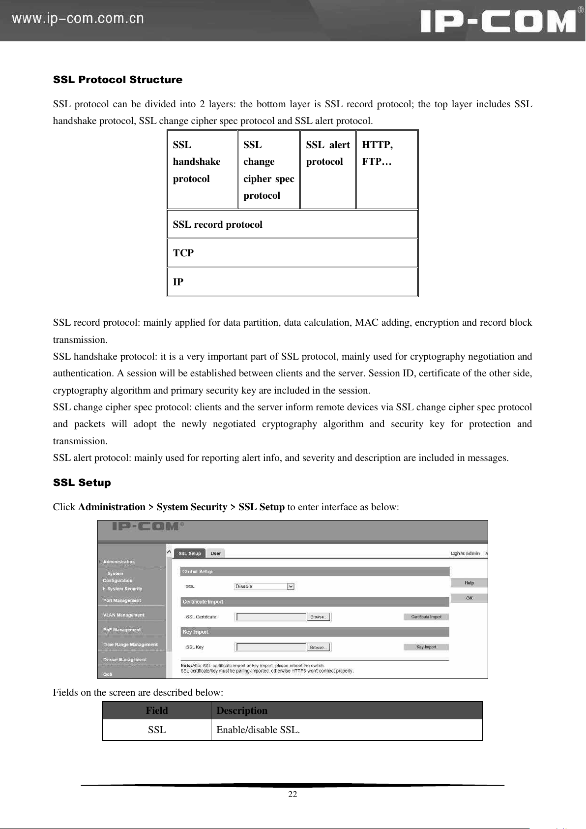
SSL Protocol Structure
SSL protocol can be divided into 2 layers: the bottom layer is SSL record protocol; the top layer includes SSL
handshake protocol, SSL change cipher spec protocol and SSL alert protocol.
SSL record protocol: mainly applied for data partition, data calculation, MAC adding, encryption and record block
transmission.
SSL handshake protocol: it is a very important part of SSL protocol, mainly used for cryptography negotiation and
authentication. A session will be established between clients and the server. Session ID, certificate of the other side,
cryptography algorithm and primary security key are included in the session.
SSL change cipher spec protocol: clients and the server inform remote devices via SSL change cipher spec protocol
and packets will adopt the newly negotiated cryptography algorithm and security key for protection and
transmission.
SSL alert protocol: mainly used for reporting alert info, and severity and description are included in messages.
SSL Setup
Click Administration > System Security > SSL Setup to enter interface as below:
Fields on the screen are described below:
22
Page 30
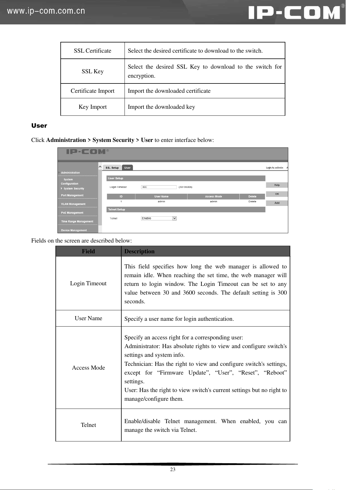
SSL Certificate
Select the desired certificate to download to the switch.
SSL Key
Select the desired SSL Key to download to the switch for
encryption.
Certificate Import
Import the downloaded certificate
Key Import
Import the downloaded key
Field
Description
Login Timeout
This field specifies how long the web manager is allowed to
remain idle. When reaching the set time, the web manager will
return to login window. The Login Timeout can be set to any
value between 30 and 3600 seconds. The default setting is 300
seconds.
User Name
Specify a user name for login authentication.
Access Mode
Specify an access right for a corresponding user:
Administrator: Has absolute rights to view and configure switch's
settings and system info.
Technician: Has the right to view and configure switch's settings,
except for ―Firmware Update‖, ―User‖, ―Reset‖, ―Reboot‖
settings.
User: Has the right to view switch's current settings but no right to
manage/configure them.
Telnet
Enable/disable Telnet management. When enabled, you can
manage the switch via Telnet.
User
Click Administration > System Security > User to enter interface below:
Fields on the screen are described below:
23
Page 31
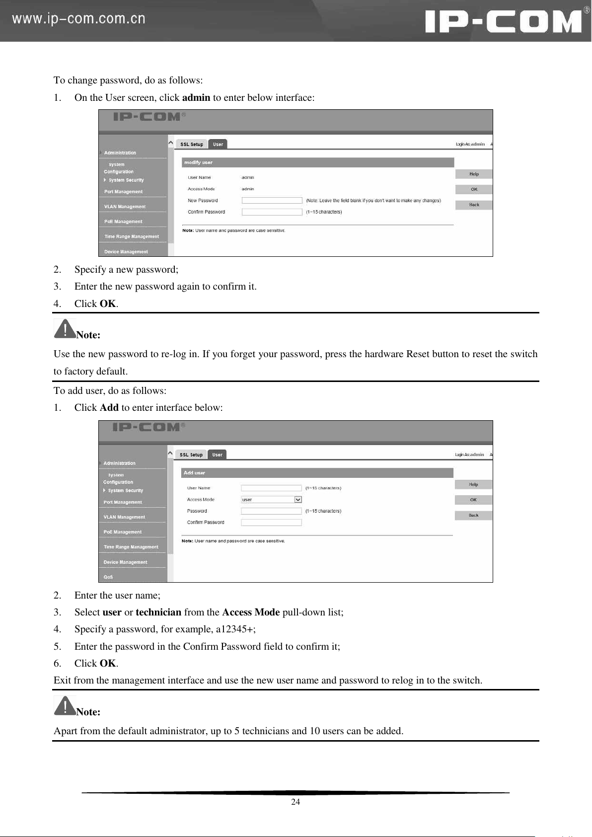
To change password, do as follows:
1. On the User screen, click admin to enter below interface:
2. Specify a new password;
3. Enter the new password again to confirm it.
4. Click OK.
Note:
Use the new password to re-log in. If you forget your password, press the hardware Reset button to reset the switch
to factory default.
To add user, do as follows:
1. Click Add to enter interface below:
2. Enter the user name;
3. Select user or technician from the Access Mode pull-down list;
4. Specify a password, for example, a12345+;
5. Enter the password in the Confirm Password field to confirm it;
6. Click OK.
Exit from the management interface and use the new user name and password to relog in to the switch.
Note:
Apart from the default administrator, up to 5 technicians and 10 users can be added.
24
Page 32
Field
Description
Link Status
Displays currently actual link rates and duplex modes on switch ports. "--" is
displayed if a port is not connected.
Speed/Duplex
Three types of duplex modes are available on Ethernet ports:
Full-duplex: Ports operating in Full-duplex mode can send and receive packets
concurrently.
Half-duplex: Ports operating in Half-duplex mode can either send or receive
packets at a given time.
Auto: Auto-negotiation, ports operating in Auto-negotiation mode determine
their duplex mode through auto-negotiation with peer ports. By default, Auto
(Auto-negotiation) is enabled for the Speed/Duplex option.
4.2 Port Management
4.2.1 Port Configuration
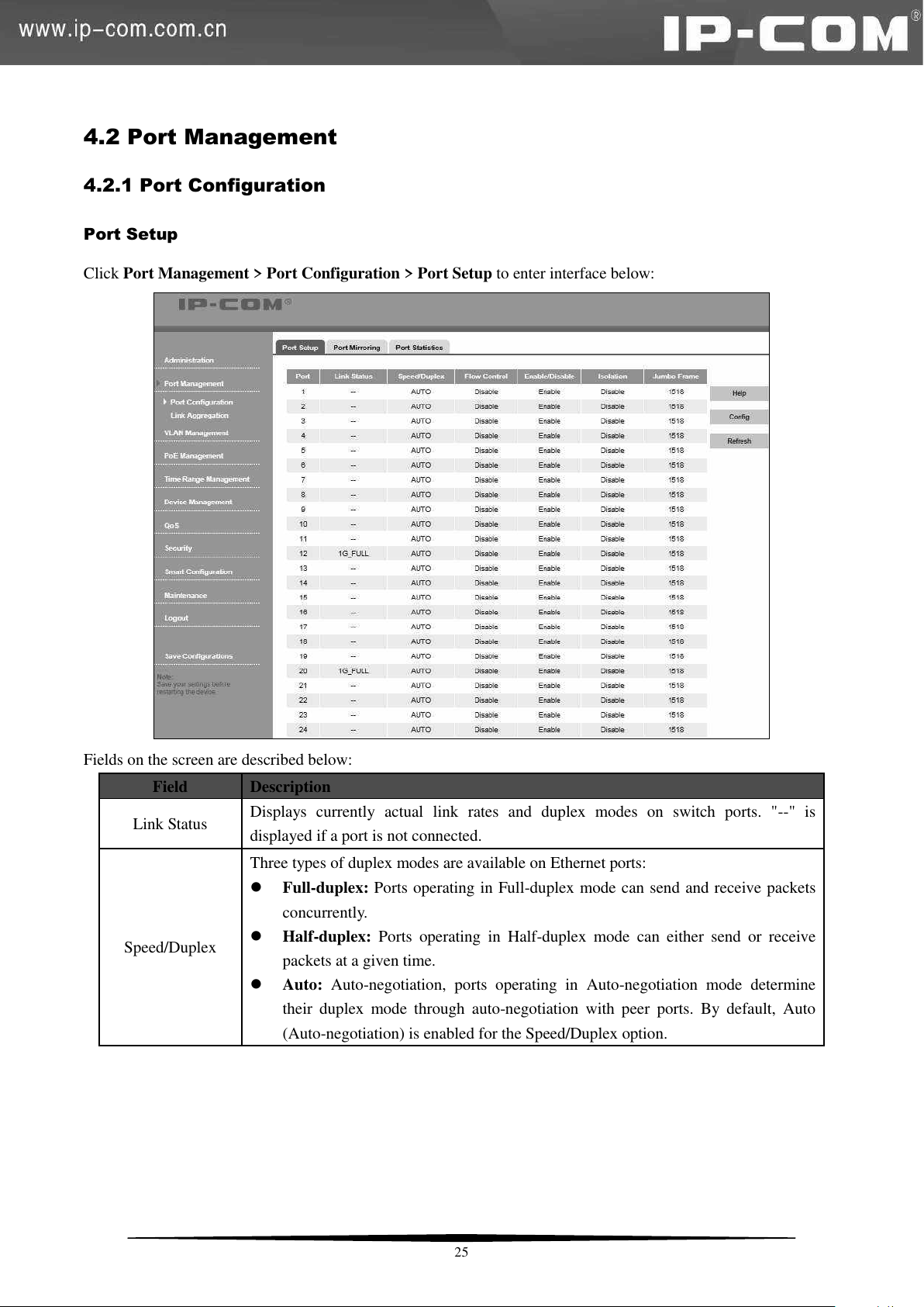
Port Setup
Click Port Management > Port Configuration > Port Setup to enter interface below:
Fields on the screen are described below:
25
Page 33
Flow Control
With flow control enabled on both the switch and its link partner, the switch, when
encountering congestion, will send flow control frames to notify the link partner of
such; upon receiving such frames, the link partner will temporarily stop sending
packets to the switch, thus avoiding packets being dropped and ensuring a reliable
network. Meanwhile, if a certain port receives Pause frame, it will also stop sending
packets out.
By default, the flow control feature is disabled.
Enable/Disable
Enable/disable selected port(s). A disabled port cannot forward packets.
By default, all ports are enabled.
Isolation
Only in 802.1Q VLAN mode, isolation feature can be set. It can implement isolation
of group members’ intercommunication by adding a port into one isolation group. This
feature helps not only deliver better security also offer flexible networking solutions.
By default, isolation feature is disabled.
Jumbo Frame
Use this option to configure the size of a jumbo frame (1518-9216) that the switch is
to receive. The switch continues data processing within the jumbo frame range. The
default jumbo frame size is 1518.
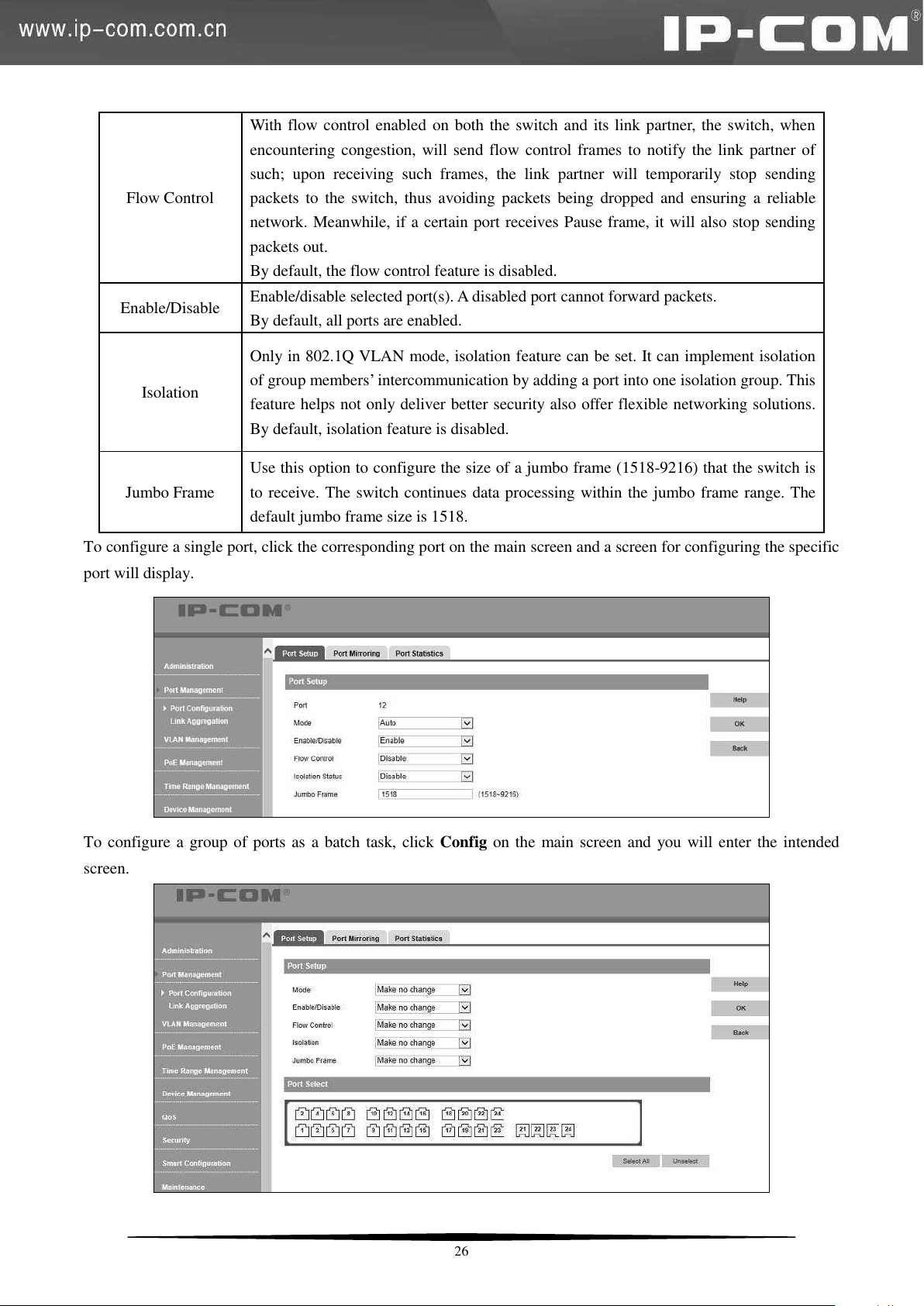
To configure a single port, click the corresponding port on the main screen and a screen for configuring the specific
port will display.
To configure a group of ports as a batch task, click Config on the main screen and you will enter the intended
screen.
26
Page 34
Field
Description
Mirroring Destination Port
Select a mirroring destination port. "None" indicates disabling the
mirroring feature.
A port cannot be set as the mirrored port and the mirroring
destination port simultaneously.
Only after a mirroring destination port is set, can you select
mirroring source port(s).
Note:
1. This device does not support half-duplex flow control. Enabling full duplex flow control can avoid packets loss,
but will influence the communication speed between source interfaces and other devices. Thus, do not enable full
duplex flow control on interfaces which connected to the Internet unless necessary.
2. Only ports in the same isolation group cannot intercommunicate. And intercommunication between ports within
an isolation group and ports outside such group will not be affected.
3. When a port in an aggregation group joins or leaves an isolation group, other ports in such aggregation group
will join or leave the same isolation group automatically.
4. When a port in an aggregation group leaves its aggregation group, other ports in such aggregation group will
remain in the same isolation group, namely, isolation properties for ports in an aggregation will not be affected.
5. When a not isolated port joins an isolated aggregation group, it joins the same isolation group automatically.
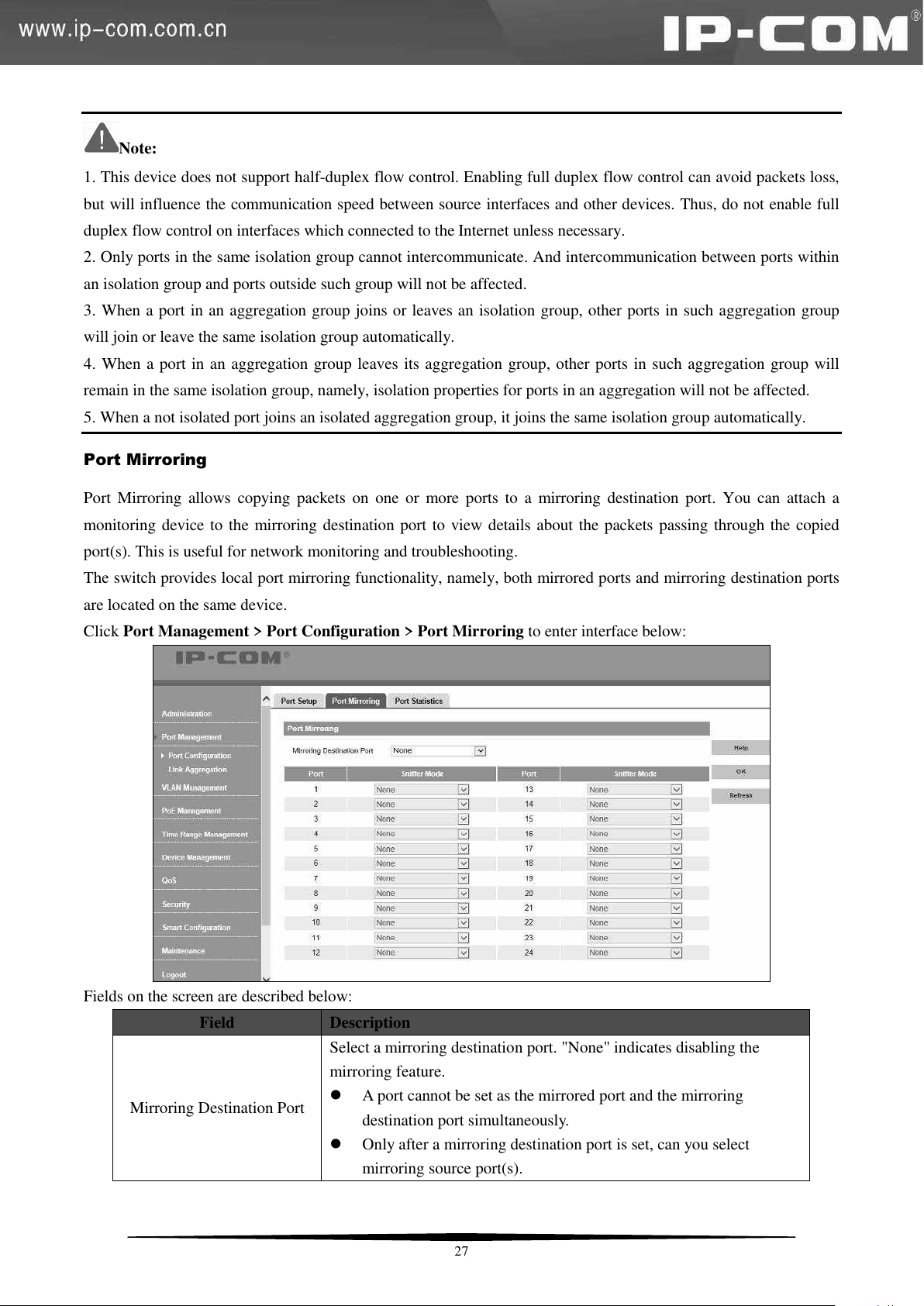
Port Mirroring
Port Mirroring allows copying packets on one or more ports to a mirroring destination port. You can attach a
monitoring device to the mirroring destination port to view details about the packets passing through the copied
port(s). This is useful for network monitoring and troubleshooting.
The switch provides local port mirroring functionality, namely, both mirrored ports and mirroring destination ports
are located on the same device.
Click Port Management > Port Configuration > Port Mirroring to enter interface below:
Fields on the screen are described below:
27
Page 35
A port in an aggregation group cannot be configured as a mirroring
destination port.
A STP-enabled and 802.1X authenticated port can't be configured
as a mirroring destination port.
Sniffer Mode
Select a sniffer mode for a corresponding mirroring source port. "None"
indicates corresponding port is not mirrored. Mirroring can be
implemented on packets of different directions (incoming/outgoing) on
different ports concurrently. When total bandwidth of the mirrored port
exceeds that of the mirroring port, packets loss will happen.
Ingress: Only incoming packets are copied to the monitor port.
Egress: Only outgoing packets are copied to the monitor port.
Egress & Ingress: Both inbound and outbound packets on the
corresponding port are copied to the monitor port (mirroring
destination port).
Note:
1. The mirroring destination port speed should be greater than that of total speed of all mirrored ports. So we
recommend you configure the mirrored port as the routing port, namely, the port connected to the Internet, to
monitor all packets.
2. Only one copy is allowed for the same data flow.
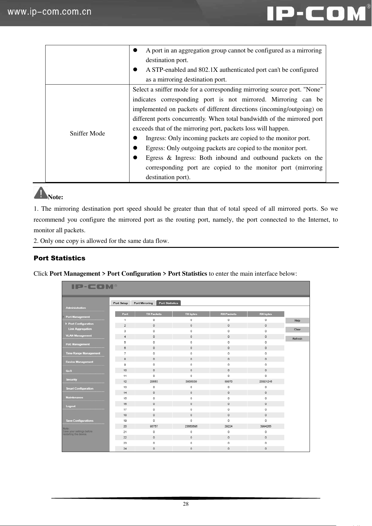
Port Statistics
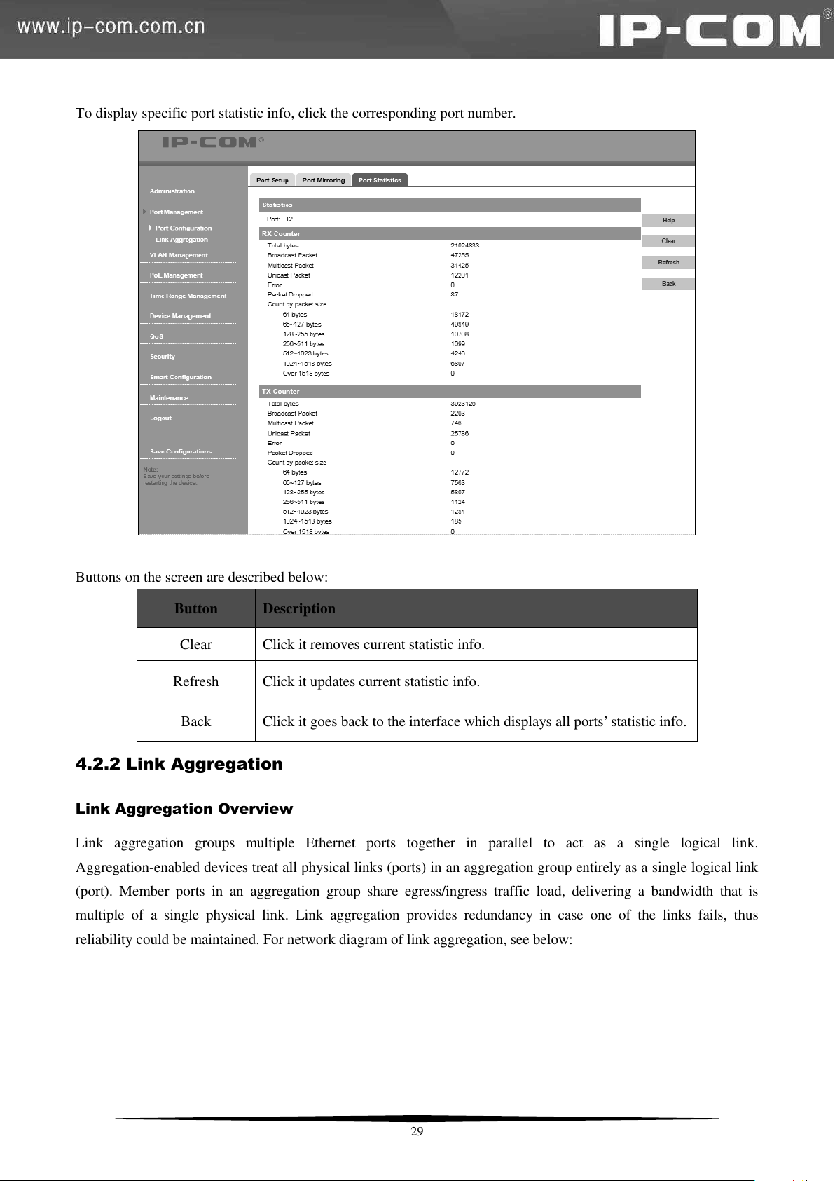
Click Port Management > Port Configuration > Port Statistics to enter the main interface below:
28
Page 36
Button
Description
Clear
Click it removes current statistic info.
Refresh
Click it updates current statistic info.
Back
Click it goes back to the interface which displays all ports’ statistic info.
To display specific port statistic info, click the corresponding port number.
Buttons on the screen are described below:
4.2.2 Link Aggregation
Link Aggregation Overview
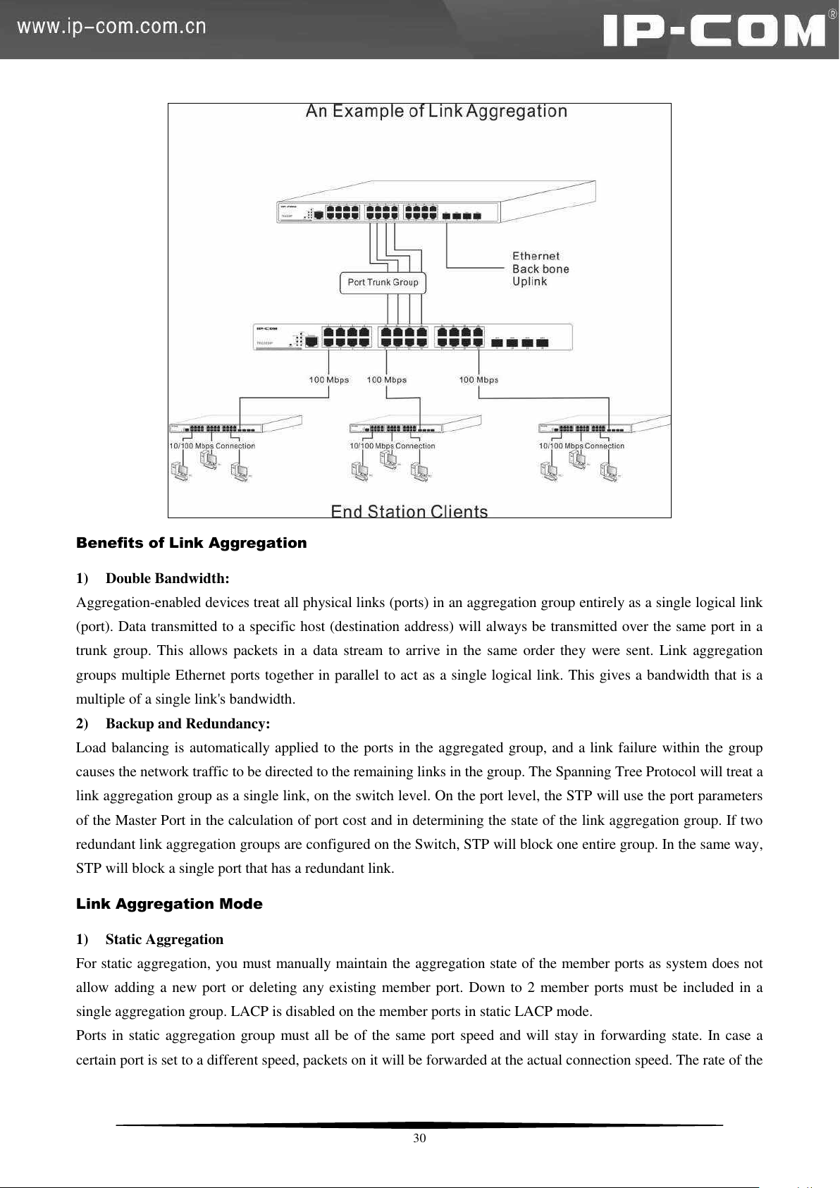
Link aggregation groups multiple Ethernet ports together in parallel to act as a single logical link.
Aggregation-enabled devices treat all physical links (ports) in an aggregation group entirely as a single logical link
(port). Member ports in an aggregation group share egress/ingress traffic load, delivering a bandwidth that is
multiple of a single physical link. Link aggregation provides redundancy in case one of the links fails, thus
reliability could be maintained. For network diagram of link aggregation, see below:
29
Page 37
Benefits of Link Aggregation
1) Double Bandwidth:
Aggregation-enabled devices treat all physical links (ports) in an aggregation group entirely as a single logical link
(port). Data transmitted to a specific host (destination address) will always be transmitted over the same port in a
trunk group. This allows packets in a data stream to arrive in the same order they were sent. Link aggregation
groups multiple Ethernet ports together in parallel to act as a single logical link. This gives a bandwidth that is a
multiple of a single link's bandwidth.
2) Backup and Redundancy:
Load balancing is automatically applied to the ports in the aggregated group, and a link failure within the group
causes the network traffic to be directed to the remaining links in the group. The Spanning Tree Protocol will treat a
link aggregation group as a single link, on the switch level. On the port level, the STP will use the port parameters
of the Master Port in the calculation of port cost and in determining the state of the link aggregation group. If two
redundant link aggregation groups are configured on the Switch, STP will block one entire group. In the same way,
STP will block a single port that has a redundant link.
Link Aggregation Mode
1) Static Aggregation
For static aggregation, you must manually maintain the aggregation state of the member ports as system does not
allow adding a new port or deleting any existing member port. Down to 2 member ports must be included in a
single aggregation group. LACP is disabled on the member ports in static LACP mode.
Ports in static aggregation group must all be of the same port speed and will stay in forwarding state. In case a
certain port is set to a different speed, packets on it will be forwarded at the actual connection speed. The rate of the
30
Page 38
Algorithm
Description
Source MAC
Member ports in a link aggregation group share traffic load according to
source MAC addresses.
Dest MAC
Member ports in a link aggregation group share traffic load according to
destination MAC addresses.
Source & Dest MAC
Member ports in a link aggregation group share traffic load according to
source and destination MAC addresses.
Source & Dest IP
Member ports in a link aggregation group share traffic load according to
source and destination IP addresses.
aggregation group equals the total rate of its member ports.
2) LACP
For LACP aggregation, you must manually maintain the aggregation state of the member ports. Whether ports in
LACP group are aggregation ports or not is determined by LLDPBU frame auto-negotiation. Down to 2 member
ports must be included in a single aggregation group. LACP is enabled on the member ports in LACP mode.
Ports in an LACP aggregation group may stay either in a forwarding status or a blocked status. Ports in LACP
aggregation group will be in a forwarding status. If all ports in the aggregation group are not aggregated, only the
first port will be in the forwarding status. Ports in forwarding status can send/receive both service packets and
LACP frames; ports in blocked status can only send/receive LACP frames.
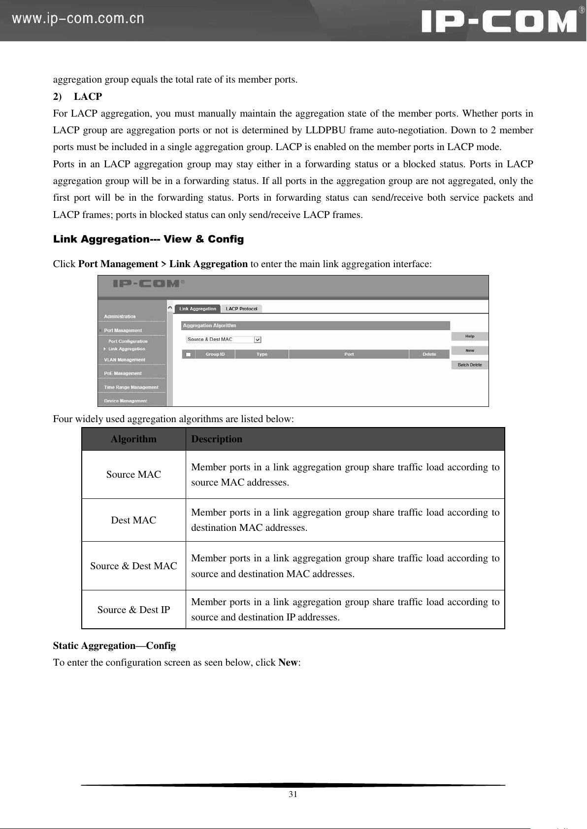
Link Aggregation--- View & Config
Click Port Management > Link Aggregation to enter the main link aggregation interface:
Four widely used aggregation algorithms are listed below:
Static Aggregation—Config
To enter the configuration screen as seen below, click New:
31
Page 39
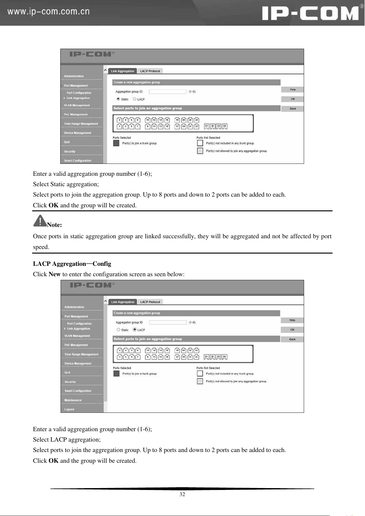
Enter a valid aggregation group number (1-6);
Select Static aggregation;
Select ports to join the aggregation group. Up to 8 ports and down to 2 ports can be added to each.
Click OK and the group will be created.
Note:
Once ports in static aggregation group are linked successfully, they will be aggregated and not be affected by port
speed.
LACP Aggregation—Config
Click New to enter the configuration screen as seen below:
Enter a valid aggregation group number (1-6);
Select LACP aggregation;
Select ports to join the aggregation group. Up to 8 ports and down to 2 ports can be added to each.
Click OK and the group will be created.
32
Page 40
Field
Description
System Priority
Configure system priority (0-65535). The default is 32768.
LACP Status
Displays Enable when corresponding port joins an LACP
aggregation group and Disable when the port does not join any
LACP aggregation group or joined a static aggregation group.
Priority
Configure port priority (0-65535). The default is 32768.
Timeout
Select a LACP timeout: long or short. The default is long.
Group ID
Displays the LACP aggregation group ID.
LACP Parameters—Config
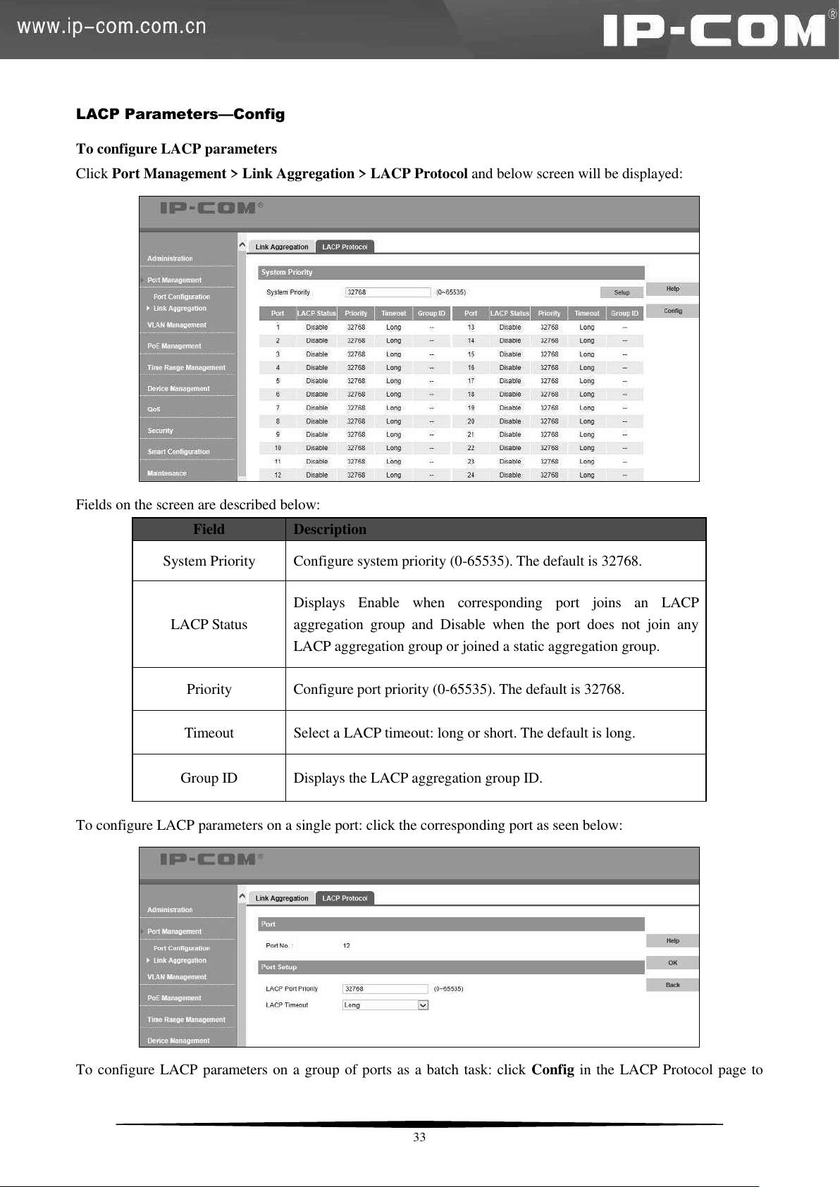
To configure LACP parameters
Click Port Management > Link Aggregation > LACP Protocol and below screen will be displayed:
Fields on the screen are described below:
To configure LACP parameters on a single port: click the corresponding port as seen below:
To configure LACP parameters on a group of ports as a batch task: click Config in the LACP Protocol page to
33
Page 41
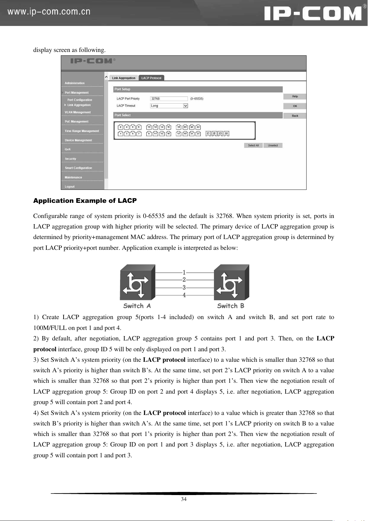
display screen as following.
Switch A
Switch B
2
3
4
1
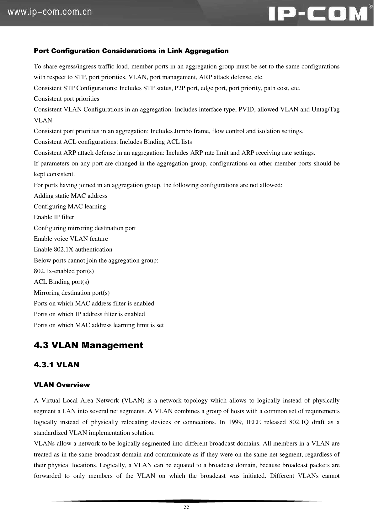
Application Example of LACP
Configurable range of system priority is 0-65535 and the default is 32768. When system priority is set, ports in
LACP aggregation group with higher priority will be selected. The primary device of LACP aggregation group is
determined by priority+management MAC address. The primary port of LACP aggregation group is determined by
port LACP priority+port number. Application example is interpreted as below:
1) Create LACP aggregation group 5(ports 1-4 included) on switch A and switch B, and set port rate to
100M/FULL on port 1 and port 4.
2) By default, after negotiation, LACP aggregation group 5 contains port 1 and port 3. Then, on the LACP
protocol interface, group ID 5 will be only displayed on port 1 and port 3.
3) Set Switch A’s system priority (on the LACP protocol interface) to a value which is smaller than 32768 so that
switch A’s priority is higher than switch B’s. At the same time, set port 2’s LACP priority on switch A to a value
which is smaller than 32768 so that port 2’s priority is higher than port 1’s. Then view the negotiation result of
LACP aggregation group 5: Group ID on port 2 and port 4 displays 5, i.e. after negotiation, LACP aggregation
group 5 will contain port 2 and port 4.
4) Set Switch A’s system priority (on the LACP protocol interface) to a value which is greater than 32768 so that
switch B’s priority is higher than switch A’s. At the same time, set port 1’s LACP priority on switch B to a value
which is smaller than 32768 so that port 1’s priority is higher than port 2’s. Then view the negotiation result of
LACP aggregation group 5: Group ID on port 1 and port 3 displays 5, i.e. after negotiation, LACP aggregation
group 5 will contain port 1 and port 3.
34
Page 42
Port Configuration Considerations in Link Aggregation
To share egress/ingress traffic load, member ports in an aggregation group must be set to the same configurations
with respect to STP, port priorities, VLAN, port management, ARP attack defense, etc.
Consistent STP Configurations: Includes STP status, P2P port, edge port, port priority, path cost, etc.
Consistent port priorities
Consistent VLAN Configurations in an aggregation: Includes interface type, PVID, allowed VLAN and Untag/Tag
VLAN.
Consistent port priorities in an aggregation: Includes Jumbo frame, flow control and isolation settings.
Consistent ACL configurations: Includes Binding ACL lists
Consistent ARP attack defense in an aggregation: Includes ARP rate limit and ARP receiving rate settings.
If parameters on any port are changed in the aggregation group, configurations on other member ports should be
kept consistent.
For ports having joined in an aggregation group, the following configurations are not allowed:
Adding static MAC address
Configuring MAC learning
Enable IP filter
Configuring mirroring destination port
Enable voice VLAN feature
Enable 802.1X authentication
Below ports cannot join the aggregation group:
802.1x-enabled port(s)
ACL Binding port(s)
Mirroring destination port(s)
Ports on which MAC address filter is enabled
Ports on which IP address filter is enabled
Ports on which MAC address learning limit is set
4.3 VLAN Management
4.3.1 VLAN
VLAN Overview
A Virtual Local Area Network (VLAN) is a network topology which allows to logically instead of physically
segment a LAN into several net segments. A VLAN combines a group of hosts with a common set of requirements
logically instead of physically relocating devices or connections. In 1999, IEEE released 802.1Q draft as a
standardized VLAN implementation solution.
VLANs allow a network to be logically segmented into different broadcast domains. All members in a VLAN are
treated as in the same broadcast domain and communicate as if they were on the same net segment, regardless of
their physical locations. Logically, a VLAN can be equated to a broadcast domain, because broadcast packets are
forwarded to only members of the VLAN on which the broadcast was initiated. Different VLANs cannot
35
Page 43
intercommunicate directly. Inter-VLAN communication can only be achieved using a router or other layer 3
devices that are able to perform Layer 3 forwarding.
Compared with the traditional Ethernet, VLAN enjoys the following advantages:
(1) Better management and control of broadcast activity
VLANs conserve network resources by segmenting a large broadcast domain into several smaller broadcast
domains or VLAN groups and restrict all broadcast traffic to the VLAN on which the broadcast was initiated.
(2) Reduced cost
The use of VLANs to create broadcast domains eliminates the need for routers to handle this function, permitting
operation at lower latencies and cost compared to routers under heavy load and at high cost.
(3) Ease of network administration
Members of a VLAN group can be geographically dispersed as they are logically related instead of physically on
the same VLAN. Thus network administrators do not need to re-configure the network when a VLAN member
changes its location. For example, in order to better collaborate with staffs from home or abroad on a special
project a workgroup is indispensable. Using VLAN, all workstations and servers that a particular workgroup uses
can be assigned to the same VLAN. For example, in order to better collaborate with staffs from home or abroad on
a special project a workgroup is indispensable. Using VLAN, all workstations and servers that a particular
workgroup uses can be assigned to the same VLAN.
(4) Tighter network security
Different VLANs cannot intercommunicate directly. Inter-VLAN communication can only be achieved using a
router or other layer 3 devices that are able to perform Layer 3 forwarding.
VLAN Mode
The switch provides 2 VLAN modes as below:
802.1Q VLAN Mode
IEEE 802.1Q is the network standard that supports Virtual LANs (VLANs) on an Ethernet network. The standard
defines a system of VLAN tagging for Ethernet frames and the accompanying procedures to be used by bridges and
switches in handling such frames.
Port VLAN
Port VLANs limit traffic that flows into and out of switch ports. Thus, all devices connected to a port are members
of the VLAN(s) the port belongs to, whether there is a single computer directly connected to a switch, or an entire
department. Members of the same VLAN can intercommunicate. A user can belong to multiple VLANs
simultaneously. For example, if you want both user A and user B to communicate with user C while user A and
user B cannot intercommunicate, simply put user A and user C to a VLAN and user B and user C to the other
VLAN.
802.1Q VLAN
VLAN Tag
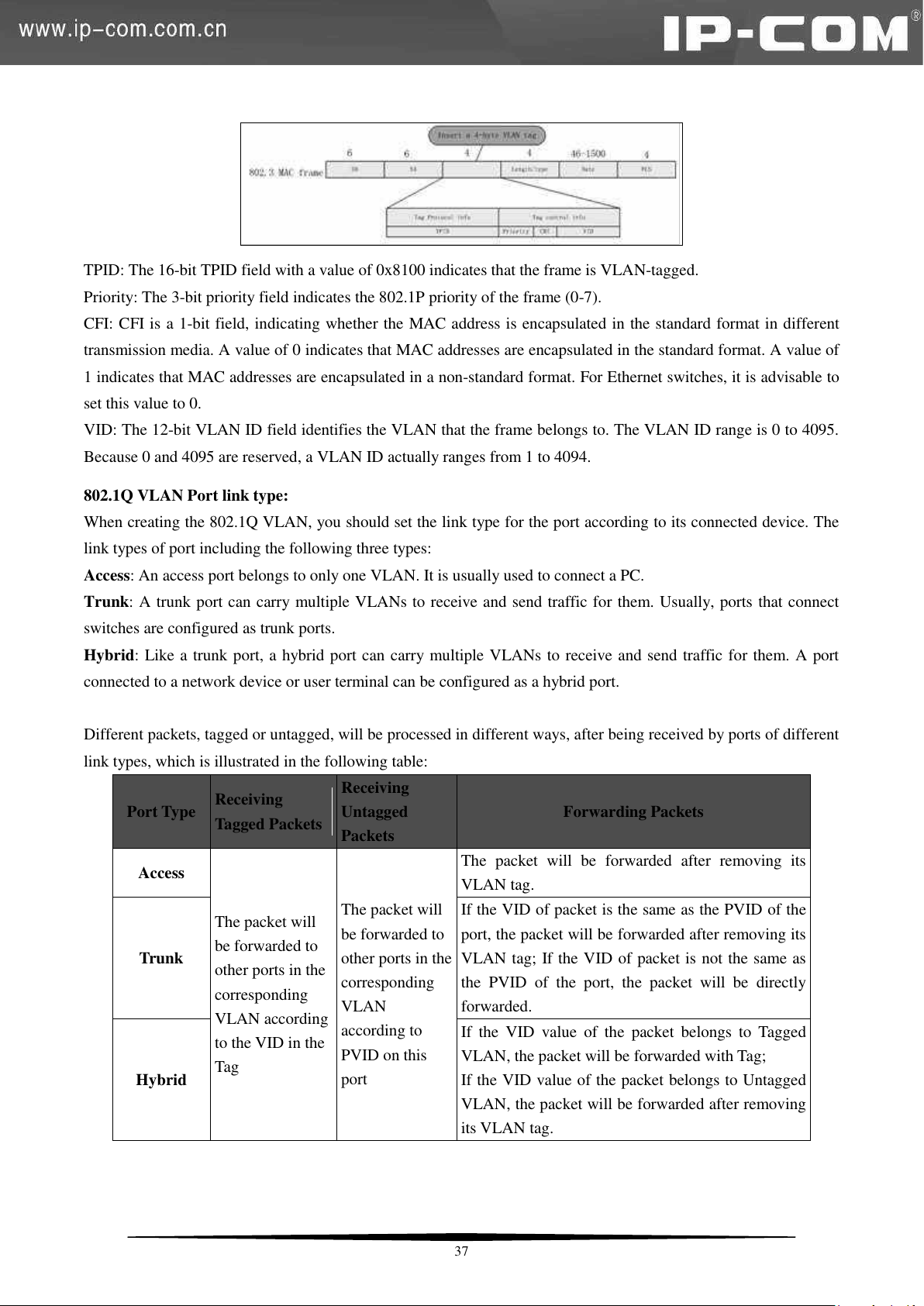
As defined in IEEE 802.1Q, a four-byte VLAN tag is inserted after the DA&SA field to identify frames of different
VLANs.
36
Page 44
Port Type
Receiving
Tagged Packets
Receiving
Untagged
Packets
Forwarding Packets
Access
The packet will
be forwarded to
other ports in the
corresponding
VLAN according
to the VID in the
Tag
The packet will
be forwarded to
other ports in the
corresponding
VLAN
according to
PVID on this
port
The packet will be forwarded after removing its
VLAN tag.
Trunk
If the VID of packet is the same as the PVID of the
port, the packet will be forwarded after removing its
VLAN tag; If the VID of packet is not the same as
the PVID of the port, the packet will be directly
forwarded.
Hybrid
If the VID value of the packet belongs to Tagged
VLAN, the packet will be forwarded with Tag;
If the VID value of the packet belongs to Untagged
VLAN, the packet will be forwarded after removing
its VLAN tag.
TPID: The 16-bit TPID field with a value of 0x8100 indicates that the frame is VLAN-tagged.
Priority: The 3-bit priority field indicates the 802.1P priority of the frame (0-7).
CFI: CFI is a 1-bit field, indicating whether the MAC address is encapsulated in the standard format in different
transmission media. A value of 0 indicates that MAC addresses are encapsulated in the standard format. A value of
1 indicates that MAC addresses are encapsulated in a non-standard format. For Ethernet switches, it is advisable to
set this value to 0.
VID: The 12-bit VLAN ID field identifies the VLAN that the frame belongs to. The VLAN ID range is 0 to 4095.
Because 0 and 4095 are reserved, a VLAN ID actually ranges from 1 to 4094.
802.1Q VLAN Port link type:
When creating the 802.1Q VLAN, you should set the link type for the port according to its connected device. The
link types of port including the following three types:
Access: An access port belongs to only one VLAN. It is usually used to connect a PC.
Trunk: A trunk port can carry multiple VLANs to receive and send traffic for them. Usually, ports that connect
switches are configured as trunk ports.
Hybrid: Like a trunk port, a hybrid port can carry multiple VLANs to receive and send traffic for them. A port
connected to a network device or user terminal can be configured as a hybrid port.
Different packets, tagged or untagged, will be processed in different ways, after being received by ports of different
link types, which is illustrated in the following table:
37
Page 45
Note:
1. PVID indicates the ID of a default VLAN that a port belongs to. The PVID for an access port is the ID of the
VLAN it belongs to; the default PVID for a trunk/hybrid port is "1" and this value is configurable.
This switch does not support ingress filter feature. Only in 802.1Q VLAN, ingress Tag packets will be forwarded
according to the VID and ingress Untag packets will be forwarded according to the PVID.
If voice VLAN, protocol VLAN, MAC VLAN and 802.1Q VLAN are configured on this switch, ingress packets
will be matched according to the VLAN sequence mentioned above.
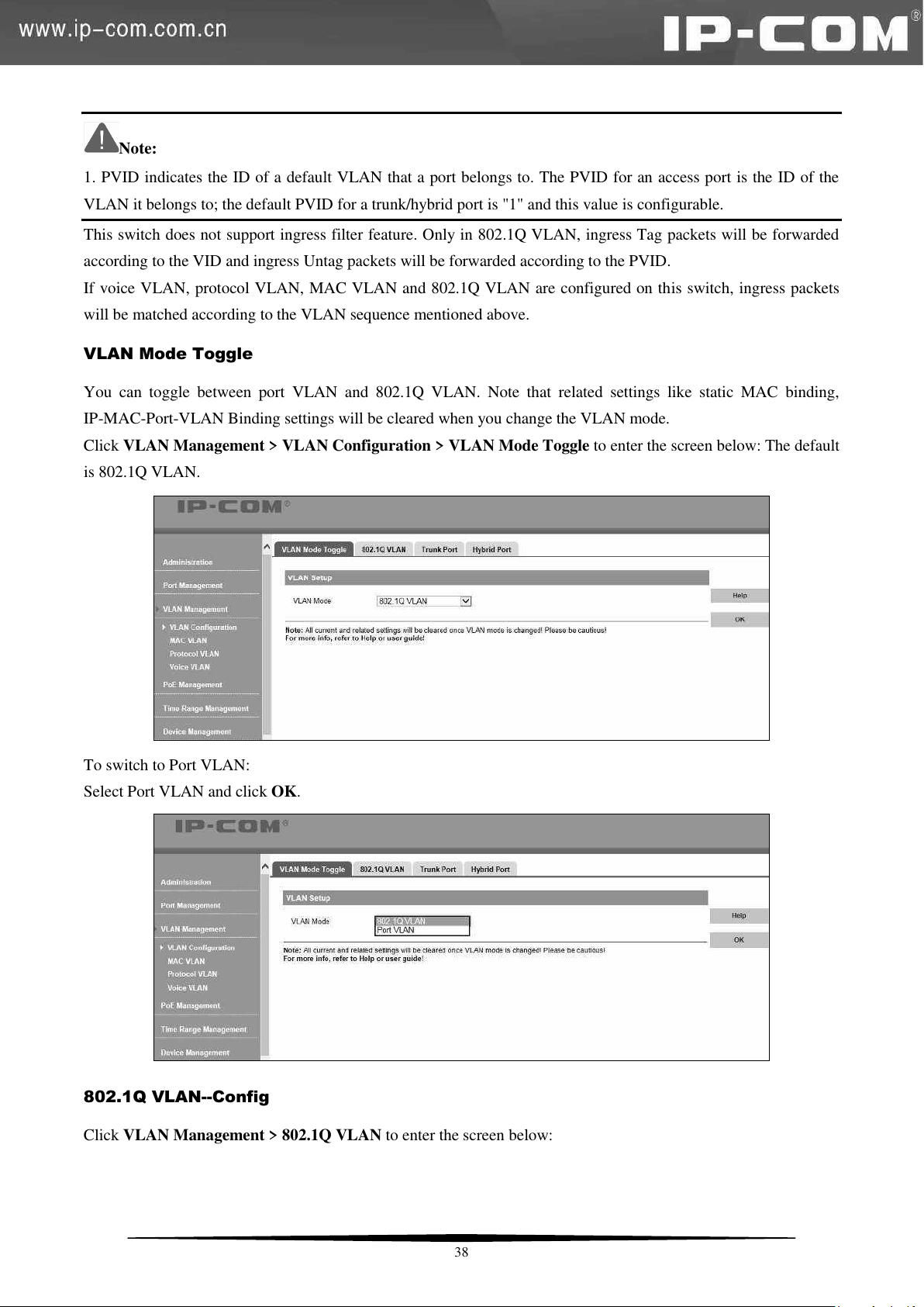
VLAN Mode Toggle
You can toggle between port VLAN and 802.1Q VLAN. Note that related settings like static MAC binding,
IP-MAC-Port-VLAN Binding settings will be cleared when you change the VLAN mode.
Click VLAN Management > VLAN Configuration > VLAN Mode Toggle to enter the screen below: The default
is 802.1Q VLAN.
To switch to Port VLAN:
Select Port VLAN and click OK.
802.1Q VLAN--Config
Click VLAN Management > 802.1Q VLAN to enter the screen below:
38
Page 46
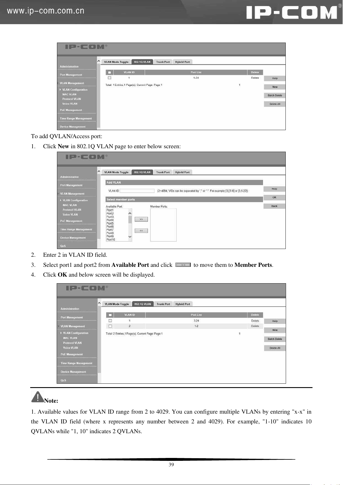
To add QVLAN/Access port:
1. Click New in 802.1Q VLAN page to enter below screen:
2. Enter 2 in VLAN ID field.
3. Select port1 and port2 from Available Port and click to move them to Member Ports.
4. Click OK and below screen will be displayed.
Note:
1. Available values for VLAN ID range from 2 to 4029. You can configure multiple VLANs by entering "x-x" in
the VLAN ID field (where x represents any number between 2 and 4029). For example, "1-10" indicates 10
QVLANs while "1, 10" indicates 2 QVLANs.
39
Page 47
2. Up to 128 QVLANs can be added.
3. By default, all ports belong to QVLAN1.
4. When a VLAN ID is deleted, ports of this VLAN ID will belong to 802.1Q VLAN1 automatically.
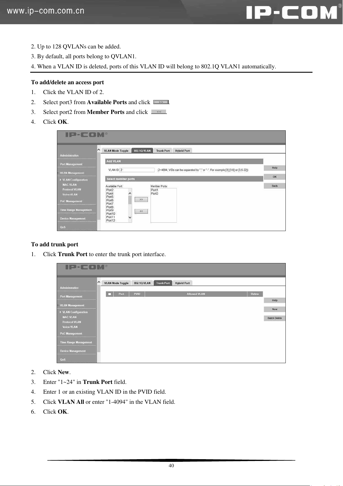
To add/delete an access port
1. Click the VLAN ID of 2.
2. Select port3 from Available Ports and click
3. Select port2 from Member Ports and click
4. Click OK.
To add trunk port
1. Click Trunk Port to enter the trunk port interface.
.
.
2. Click New.
3. Enter "1~24" in Trunk Port field.
4. Enter 1 or an existing VLAN ID in the PVID field.
5. Click VLAN All or enter "1-4094" in the VLAN field.
6. Click OK.
40
Page 48
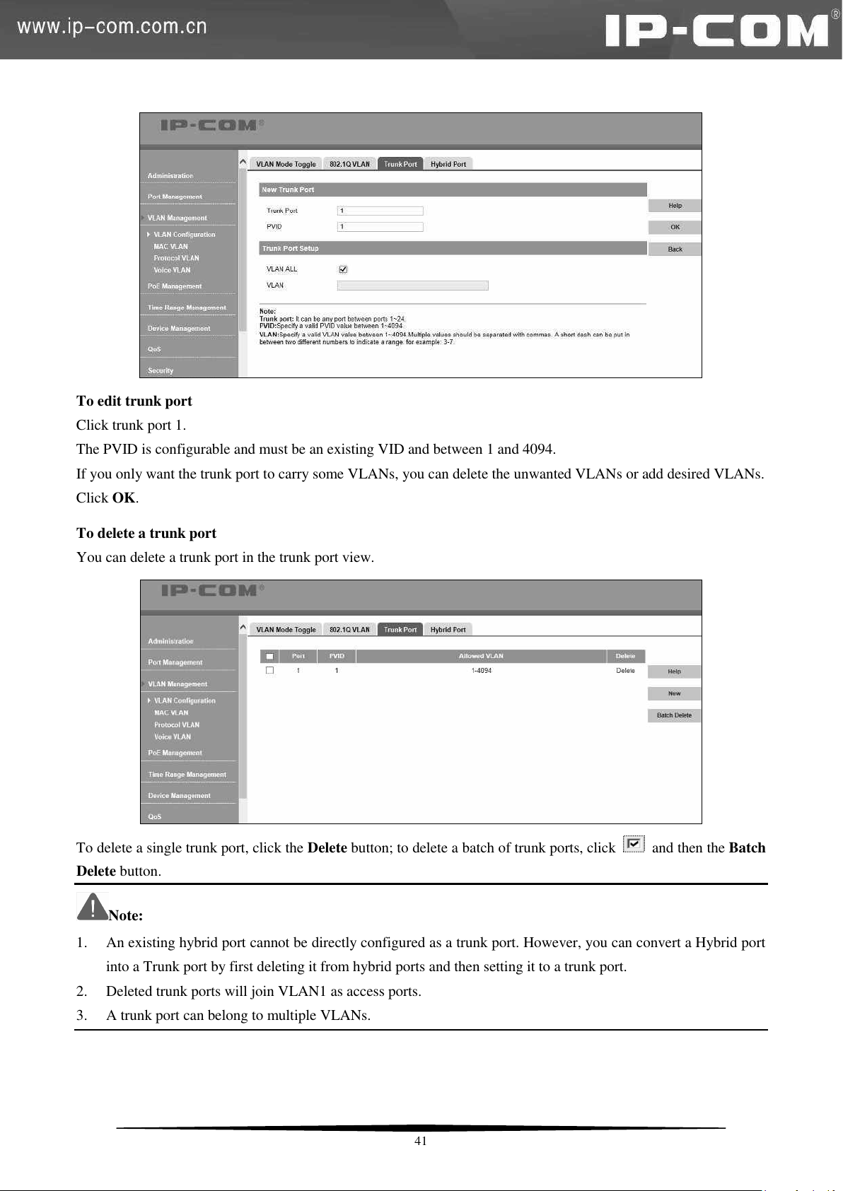
To edit trunk port
Click trunk port 1.
The PVID is configurable and must be an existing VID and between 1 and 4094.
If you only want the trunk port to carry some VLANs, you can delete the unwanted VLANs or add desired VLANs.
Click OK.
To delete a trunk port
You can delete a trunk port in the trunk port view.
To delete a single trunk port, click the Delete button; to delete a batch of trunk ports, click and then the Batch
Delete button.
Note:
1. An existing hybrid port cannot be directly configured as a trunk port. However, you can convert a Hybrid port
into a Trunk port by first deleting it from hybrid ports and then setting it to a trunk port.
2. Deleted trunk ports will join VLAN1 as access ports.
3. A trunk port can belong to multiple VLANs.
41
Page 49

To add a hybrid port
1. Click Hybrid Port to display below screen:
2. Click New and enter a port number in the Hybrid Port field. You can add multiple ports by entering "x-x" (where
x represents any number between 1 and 24). For example, "1-24" denotes 24 ports while "1, 24" indicates 2 ports.
3. PVID: Enter an existing VLAN ID.
4. Tagged VLAN: Enter 1-4094 or leave it empty.
5. Untagged VLAN: Enter 1-4094 or leave it empty.
6. Click OK.
To edit a hybrid port
1. Click the corresponding hybrid port number as seen below:
2. The PVID is configurable and should be an existing VID and between 1 and 4094.
3. Add/delete currently configured Tagged VLAN and Untagged VLAN.
4. Click OK.
42
Page 50
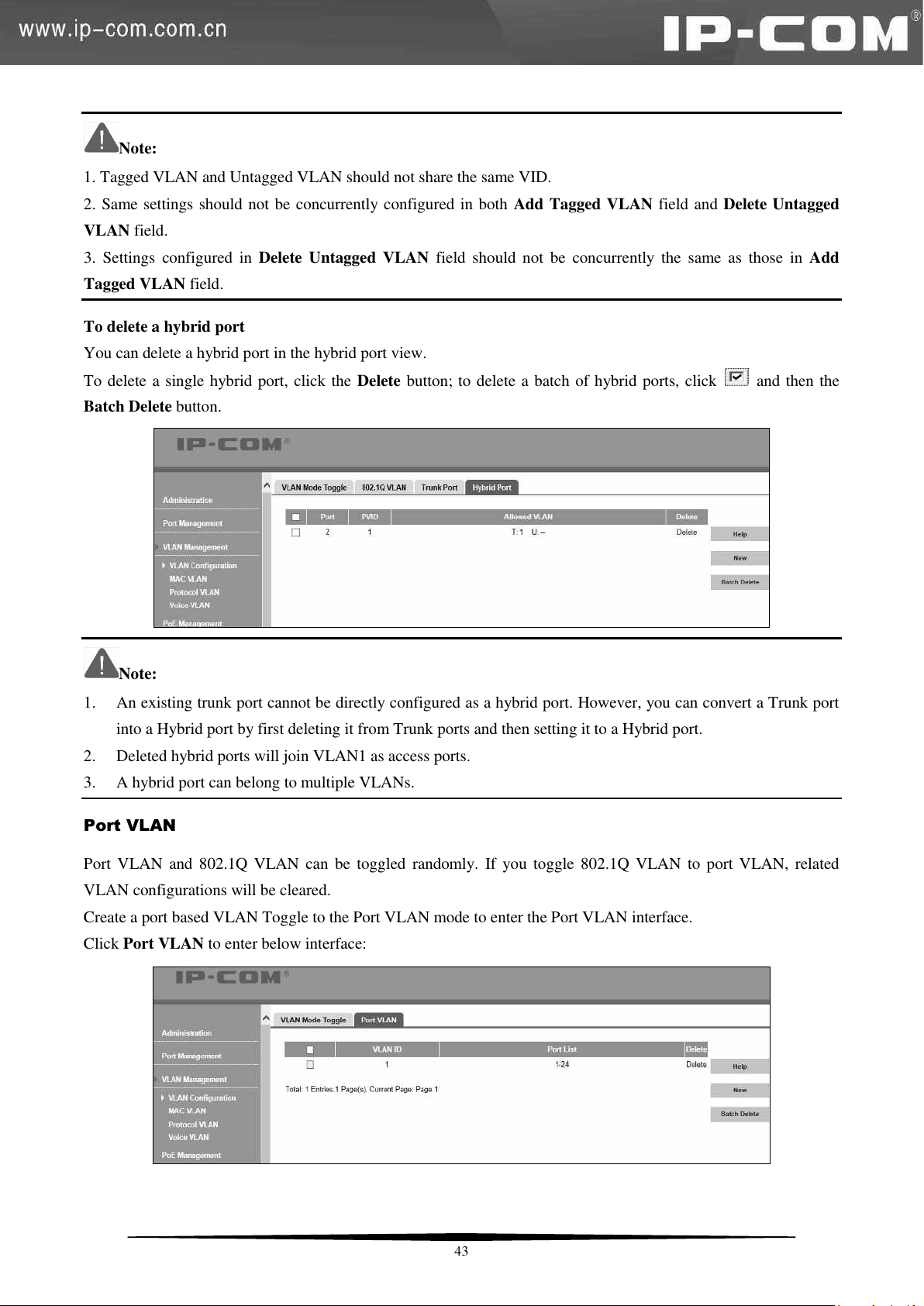
Note:
1. Tagged VLAN and Untagged VLAN should not share the same VID.
2. Same settings should not be concurrently configured in both Add Tagged VLAN field and Delete Untagged
VLAN field.
3. Settings configured in Delete Untagged VLAN field should not be concurrently the same as those in Add
Tagged VLAN field.
To delete a hybrid port
You can delete a hybrid port in the hybrid port view.
To delete a single hybrid port, click the Delete button; to delete a batch of hybrid ports, click
and then the
Batch Delete button.
Note:
1. An existing trunk port cannot be directly configured as a hybrid port. However, you can convert a Trunk port
into a Hybrid port by first deleting it from Trunk ports and then setting it to a Hybrid port.
2. Deleted hybrid ports will join VLAN1 as access ports.
3. A hybrid port can belong to multiple VLANs.
Port VLAN
Port VLAN and 802.1Q VLAN can be toggled randomly. If you toggle 802.1Q VLAN to port VLAN, related
VLAN configurations will be cleared.
Create a port based VLAN Toggle to the Port VLAN mode to enter the Port VLAN interface.
Click Port VLAN to enter below interface:
43
Page 51
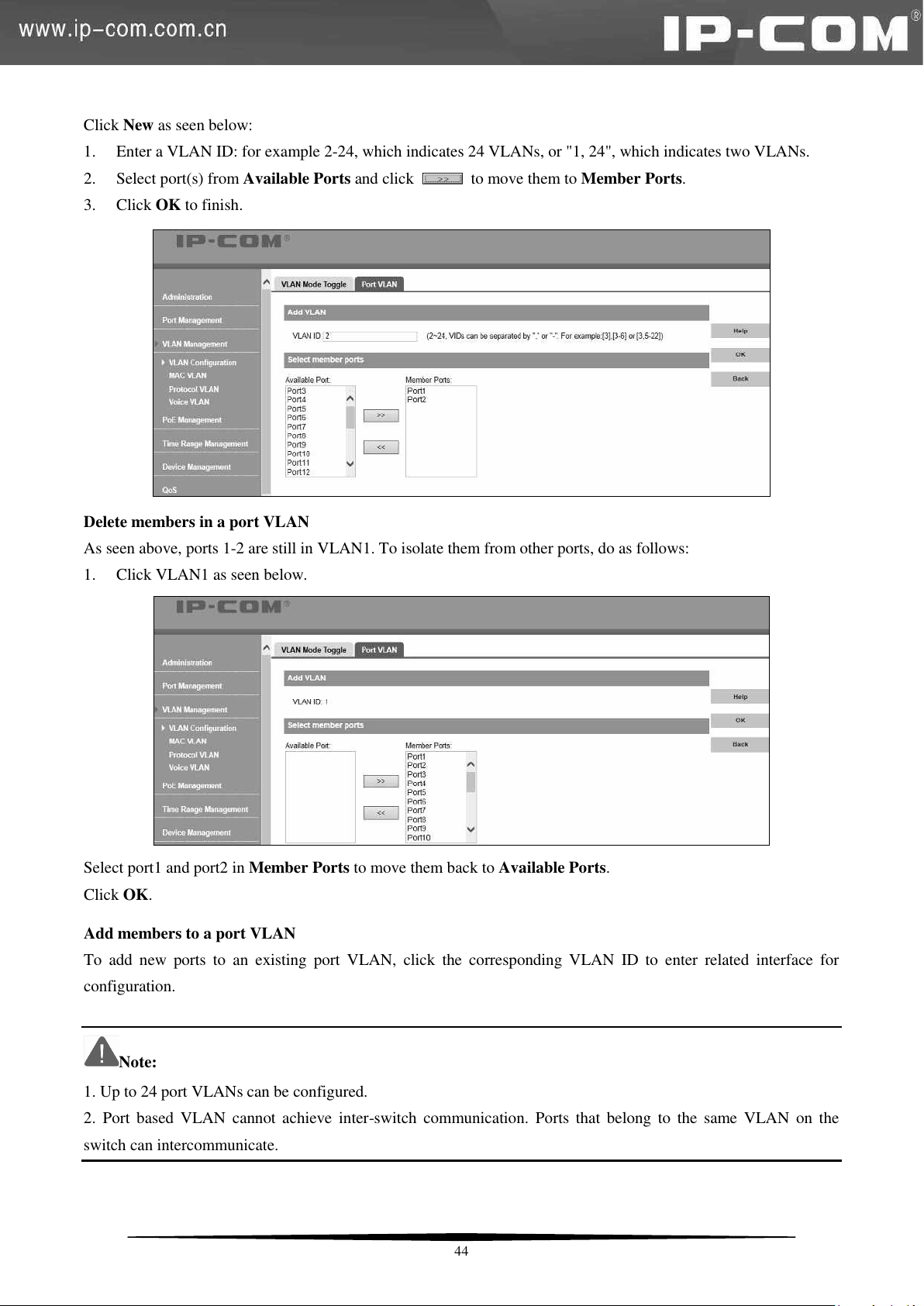
Click New as seen below:
1. Enter a VLAN ID: for example 2-24, which indicates 24 VLANs, or "1, 24", which indicates two VLANs.
2. Select port(s) from Available Ports and click
to move them to Member Ports.
3. Click OK to finish.
Delete members in a port VLAN
As seen above, ports 1-2 are still in VLAN1. To isolate them from other ports, do as follows:
1. Click VLAN1 as seen below.
Select port1 and port2 in Member Ports to move them back to Available Ports.
Click OK.
Add members to a port VLAN
To add new ports to an existing port VLAN, click the corresponding VLAN ID to enter related interface for
configuration.
Note:
1. Up to 24 port VLANs can be configured.
2. Port based VLAN cannot achieve inter-switch communication. Ports that belong to the same VLAN on the
switch can intercommunicate.
44
Page 52
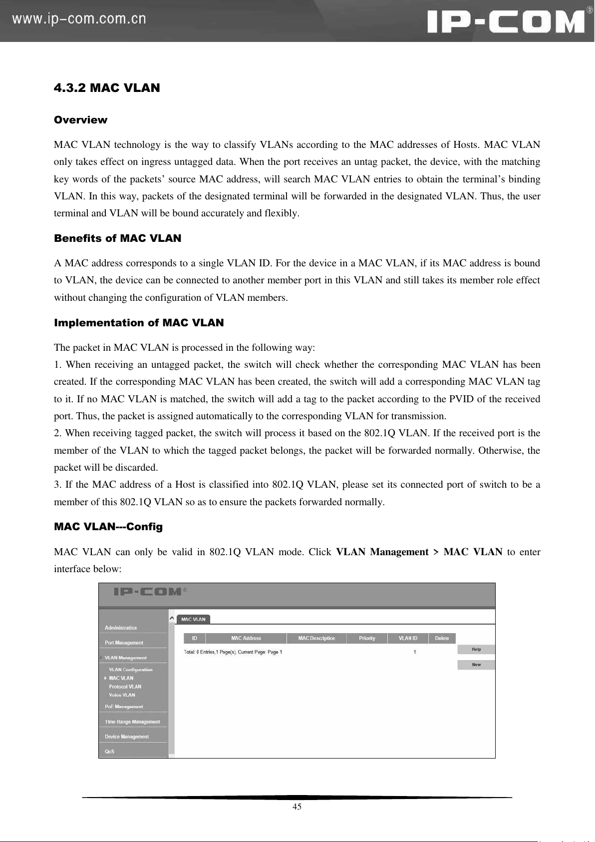
4.3.2 MAC VLAN
Overview
MAC VLAN technology is the way to classify VLANs according to the MAC addresses of Hosts. MAC VLAN
only takes effect on ingress untagged data. When the port receives an untag packet, the device, with the matching
key words of the packets’ source MAC address, will search MAC VLAN entries to obtain the terminal’s binding
VLAN. In this way, packets of the designated terminal will be forwarded in the designated VLAN. Thus, the user
terminal and VLAN will be bound accurately and flexibly.
Benefits of MAC VLAN
A MAC address corresponds to a single VLAN ID. For the device in a MAC VLAN, if its MAC address is bound
to VLAN, the device can be connected to another member port in this VLAN and still takes its member role effect
without changing the configuration of VLAN members.
Implementation of MAC VLAN
The packet in MAC VLAN is processed in the following way:
1. When receiving an untagged packet, the switch will check whether the corresponding MAC VLAN has been
created. If the corresponding MAC VLAN has been created, the switch will add a corresponding MAC VLAN tag
to it. If no MAC VLAN is matched, the switch will add a tag to the packet according to the PVID of the received
port. Thus, the packet is assigned automatically to the corresponding VLAN for transmission.
2. When receiving tagged packet, the switch will process it based on the 802.1Q VLAN. If the received port is the
member of the VLAN to which the tagged packet belongs, the packet will be forwarded normally. Otherwise, the
packet will be discarded.
3. If the MAC address of a Host is classified into 802.1Q VLAN, please set its connected port of switch to be a
member of this 802.1Q VLAN so as to ensure the packets forwarded normally.
MAC VLAN---Config
MAC VLAN can only be valid in 802.1Q VLAN mode. Click VLAN Management > MAC VLAN to enter
interface below:
45
Page 53
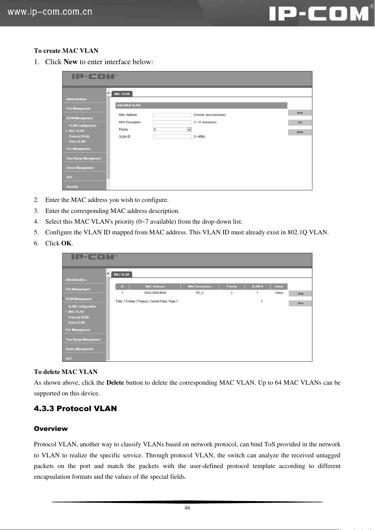
To create MAC VLAN
1. Click New to enter interface below:
2. Enter the MAC address you wish to configure.
3. Enter the corresponding MAC address description.
4. Select this MAC VLAN's priority (0~7 available) from the drop-down list.
5. Configure the VLAN ID mapped from MAC address. This VLAN ID must already exist in 802.1Q VLAN.
6. Click OK.
To delete MAC VLAN
As shown above, click the Delete button to delete the corresponding MAC VLAN. Up to 64 MAC VLANs can be
supported on this device.
4.3.3 Protocol VLAN
Overview
Protocol VLAN, another way to classify VLANs based on network protocol, can bind ToS provided in the network
to VLAN to realize the specific service. Through protocol VLAN, the switch can analyze the received untagged
packets on the port and match the packets with the user-defined protocol template according to different
encapsulation formats and the values of the special fields.
46
Page 54
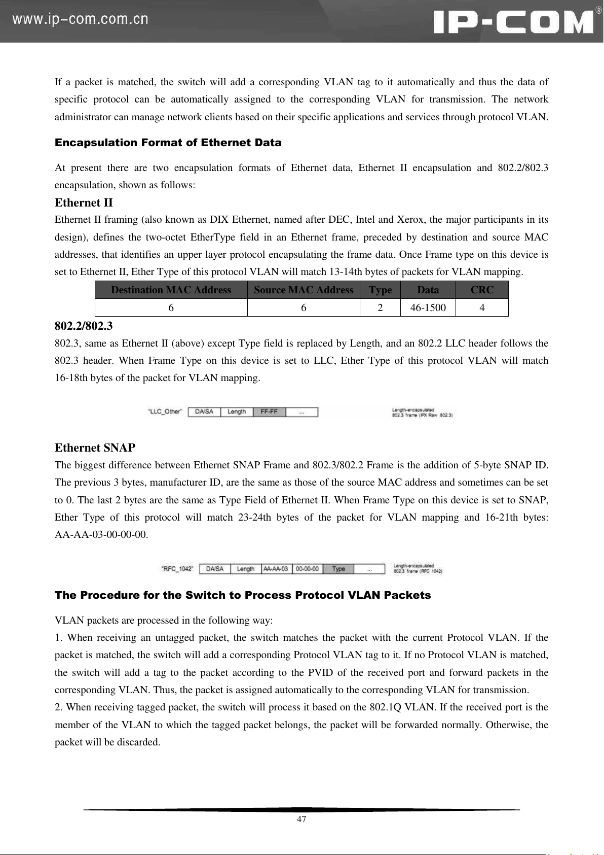
Destination MAC Address
Source MAC Address
Type
Data
CRC
6
6
2
46-1500
4
If a packet is matched, the switch will add a corresponding VLAN tag to it automatically and thus the data of
specific protocol can be automatically assigned to the corresponding VLAN for transmission. The network
administrator can manage network clients based on their specific applications and services through protocol VLAN.
Encapsulation Format of Ethernet Data
At present there are two encapsulation formats of Ethernet data, Ethernet II encapsulation and 802.2/802.3
encapsulation, shown as follows:
Ethernet II
Ethernet II framing (also known as DIX Ethernet, named after DEC, Intel and Xerox, the major participants in its
design), defines the two-octet EtherType field in an Ethernet frame, preceded by destination and source MAC
addresses, that identifies an upper layer protocol encapsulating the frame data. Once Frame type on this device is
set to Ethernet II, Ether Type of this protocol VLAN will match 13-14th bytes of packets for VLAN mapping.
802.2/802.3
802.3, same as Ethernet II (above) except Type field is replaced by Length, and an 802.2 LLC header follows the
802.3 header. When Frame Type on this device is set to LLC, Ether Type of this protocol VLAN will match
16-18th bytes of the packet for VLAN mapping.
Ethernet SNAP
The biggest difference between Ethernet SNAP Frame and 802.3/802.2 Frame is the addition of 5-byte SNAP ID.
The previous 3 bytes, manufacturer ID, are the same as those of the source MAC address and sometimes can be set
to 0. The last 2 bytes are the same as Type Field of Ethernet II. When Frame Type on this device is set to SNAP,
Ether Type of this protocol will match 23-24th bytes of the packet for VLAN mapping and 16-21th bytes:
AA-AA-03-00-00-00.
The Procedure for the Switch to Process Protocol VLAN Packets
VLAN packets are processed in the following way:
1. When receiving an untagged packet, the switch matches the packet with the current Protocol VLAN. If the
packet is matched, the switch will add a corresponding Protocol VLAN tag to it. If no Protocol VLAN is matched,
the switch will add a tag to the packet according to the PVID of the received port and forward packets in the
corresponding VLAN. Thus, the packet is assigned automatically to the corresponding VLAN for transmission.
2. When receiving tagged packet, the switch will process it based on the 802.1Q VLAN. If the received port is the
member of the VLAN to which the tagged packet belongs, the packet will be forwarded normally. Otherwise, the
packet will be discarded.
47
Page 55
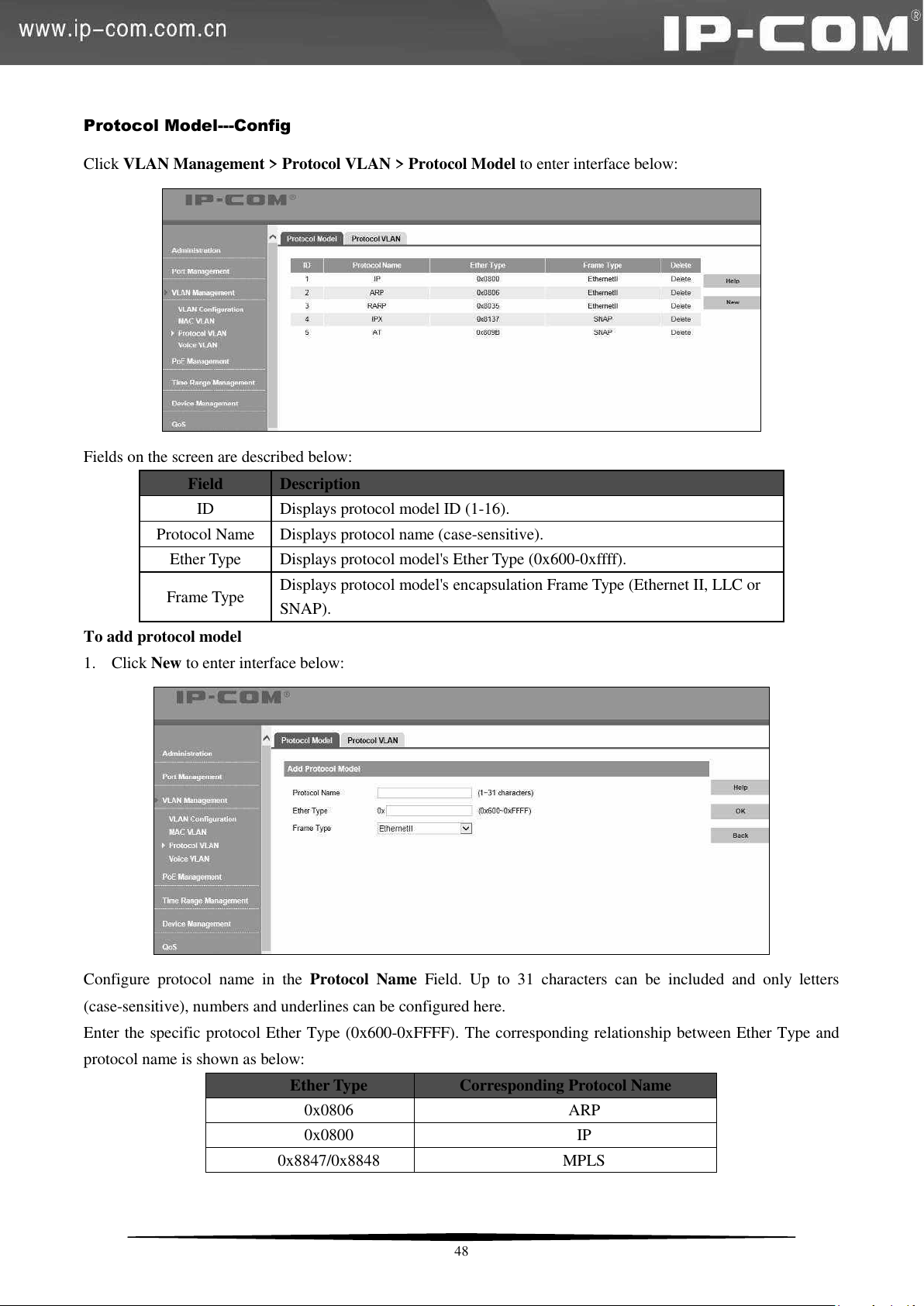
Field
Description
ID
Displays protocol model ID (1-16).
Protocol Name
Displays protocol name (case-sensitive).
Ether Type
Displays protocol model's Ether Type (0x600-0xffff).
Frame Type
Displays protocol model's encapsulation Frame Type (Ethernet II, LLC or
SNAP).
Ether Type
Corresponding Protocol Name
0x0806
ARP
0x0800
IP
0x8847/0x8848
MPLS
Protocol Model---Config
Click VLAN Management > Protocol VLAN > Protocol Model to enter interface below:
Fields on the screen are described below:
To add protocol model
1. Click New to enter interface below:
Configure protocol name in the Protocol Name Field. Up to 31 characters can be included and only letters
(case-sensitive), numbers and underlines can be configured here.
Enter the specific protocol Ether Type (0x600-0xFFFF). The corresponding relationship between Ether Type and
protocol name is shown as below:
48
Page 56
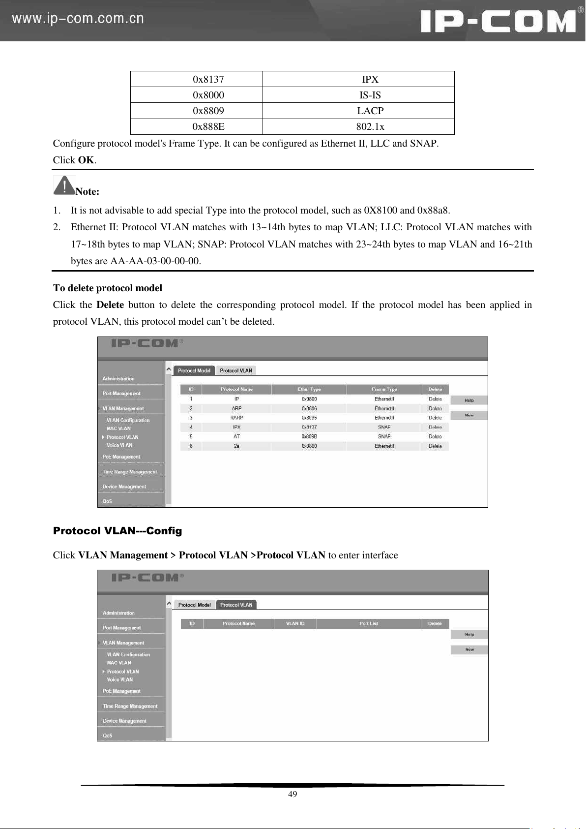
0x8137
IPX
0x8000
IS-IS
0x8809
LACP
0x888E
802.1x
Configure protocol model's Frame Type. It can be configured as Ethernet II, LLC and SNAP.
Click OK.
Note:
1. It is not advisable to add special Type into the protocol model, such as 0X8100 and 0x88a8.
2. Ethernet II: Protocol VLAN matches with 13~14th bytes to map VLAN; LLC: Protocol VLAN matches with
17~18th bytes to map VLAN; SNAP: Protocol VLAN matches with 23~24th bytes to map VLAN and 16~21th
bytes are AA-AA-03-00-00-00.
To delete protocol model
Click the Delete button to delete the corresponding protocol model. If the protocol model has been applied in
protocol VLAN, this protocol model can’t be deleted.
Protocol VLAN---Config
Click VLAN Management > Protocol VLAN >Protocol VLAN to enter interface
49
Page 57
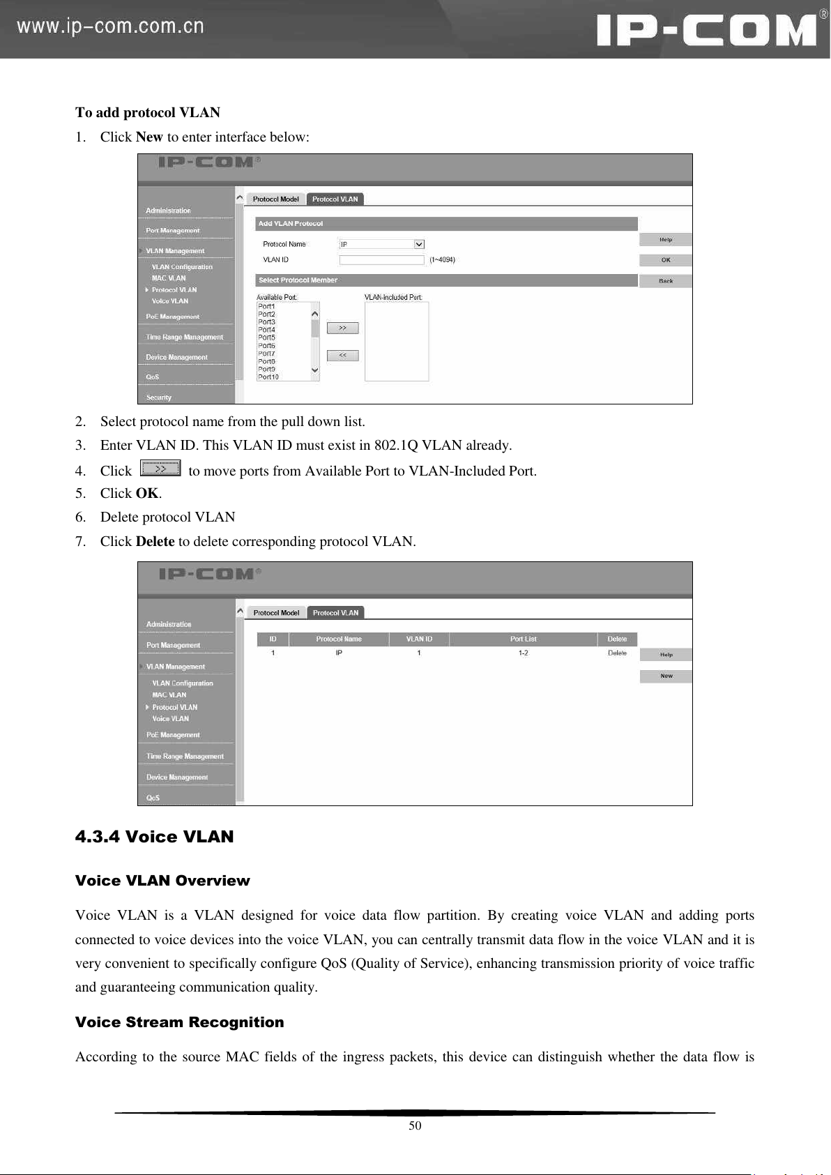
To add protocol VLAN
1. Click New to enter interface below:
2. Select protocol name from the pull down list.
3. Enter VLAN ID. This VLAN ID must exist in 802.1Q VLAN already.
4. Click to move ports from Available Port to VLAN-Included Port.
5. Click OK.
6. Delete protocol VLAN
7. Click Delete to delete corresponding protocol VLAN.
4.3.4 Voice VLAN
Voice VLAN Overview
Voice VLAN is a VLAN designed for voice data flow partition. By creating voice VLAN and adding ports
connected to voice devices into the voice VLAN, you can centrally transmit data flow in the voice VLAN and it is
very convenient to specifically configure QoS (Quality of Service), enhancing transmission priority of voice traffic
and guaranteeing communication quality.
Voice Stream Recognition
According to the source MAC fields of the ingress packets, this device can distinguish whether the data flow is
50
Page 58
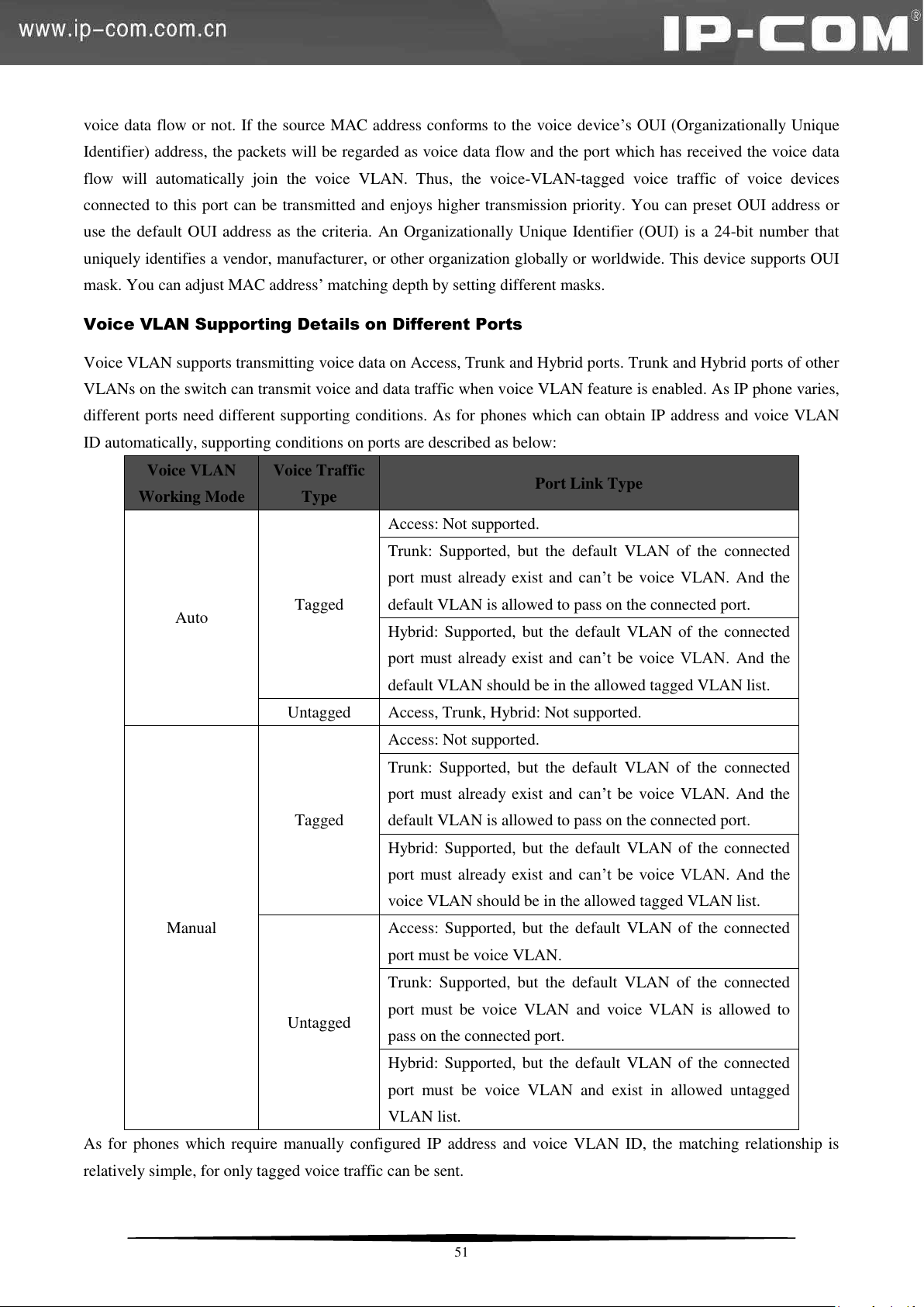
Voice VLAN
Working Mode
Voice Traffic
Type
Port Link Type
Auto
Tagged
Access: Not supported.
Trunk: Supported, but the default VLAN of the connected
port must already exist and can’t be voice VLAN. And the
default VLAN is allowed to pass on the connected port.
Hybrid: Supported, but the default VLAN of the connected
port must already exist and can’t be voice VLAN. And the
default VLAN should be in the allowed tagged VLAN list.
Untagged
Access, Trunk, Hybrid: Not supported.
Manual
Tagged
Access: Not supported.
Trunk: Supported, but the default VLAN of the connected
port must already exist and can’t be voice VLAN. And the
default VLAN is allowed to pass on the connected port.
Hybrid: Supported, but the default VLAN of the connected
port must already exist and can’t be voice VLAN. And the
voice VLAN should be in the allowed tagged VLAN list.
Untagged
Access: Supported, but the default VLAN of the connected
port must be voice VLAN.
Trunk: Supported, but the default VLAN of the connected
port must be voice VLAN and voice VLAN is allowed to
pass on the connected port.
Hybrid: Supported, but the default VLAN of the connected
port must be voice VLAN and exist in allowed untagged
VLAN list.
voice data flow or not. If the source MAC address conforms to the voice device’s OUI (Organizationally Unique
Identifier) address, the packets will be regarded as voice data flow and the port which has received the voice data
flow will automatically join the voice VLAN. Thus, the voice-VLAN-tagged voice traffic of voice devices
connected to this port can be transmitted and enjoys higher transmission priority. You can preset OUI address or
use the default OUI address as the criteria. An Organizationally Unique Identifier (OUI) is a 24-bit number that
uniquely identifies a vendor, manufacturer, or other organization globally or worldwide. This device supports OUI
mask. You can adjust MAC address’ matching depth by setting different masks.
Voice VLAN Supporting Details on Different Ports
Voice VLAN supports transmitting voice data on Access, Trunk and Hybrid ports. Trunk and Hybrid ports of other
VLANs on the switch can transmit voice and data traffic when voice VLAN feature is enabled. As IP phone varies,
different ports need different supporting conditions. As for phones which can obtain IP address and voice VLAN
ID automatically, supporting conditions on ports are described as below:
As for phones which require manually configured IP address and voice VLAN ID, the matching relationship is
relatively simple, for only tagged voice traffic can be sent.
51
Page 59
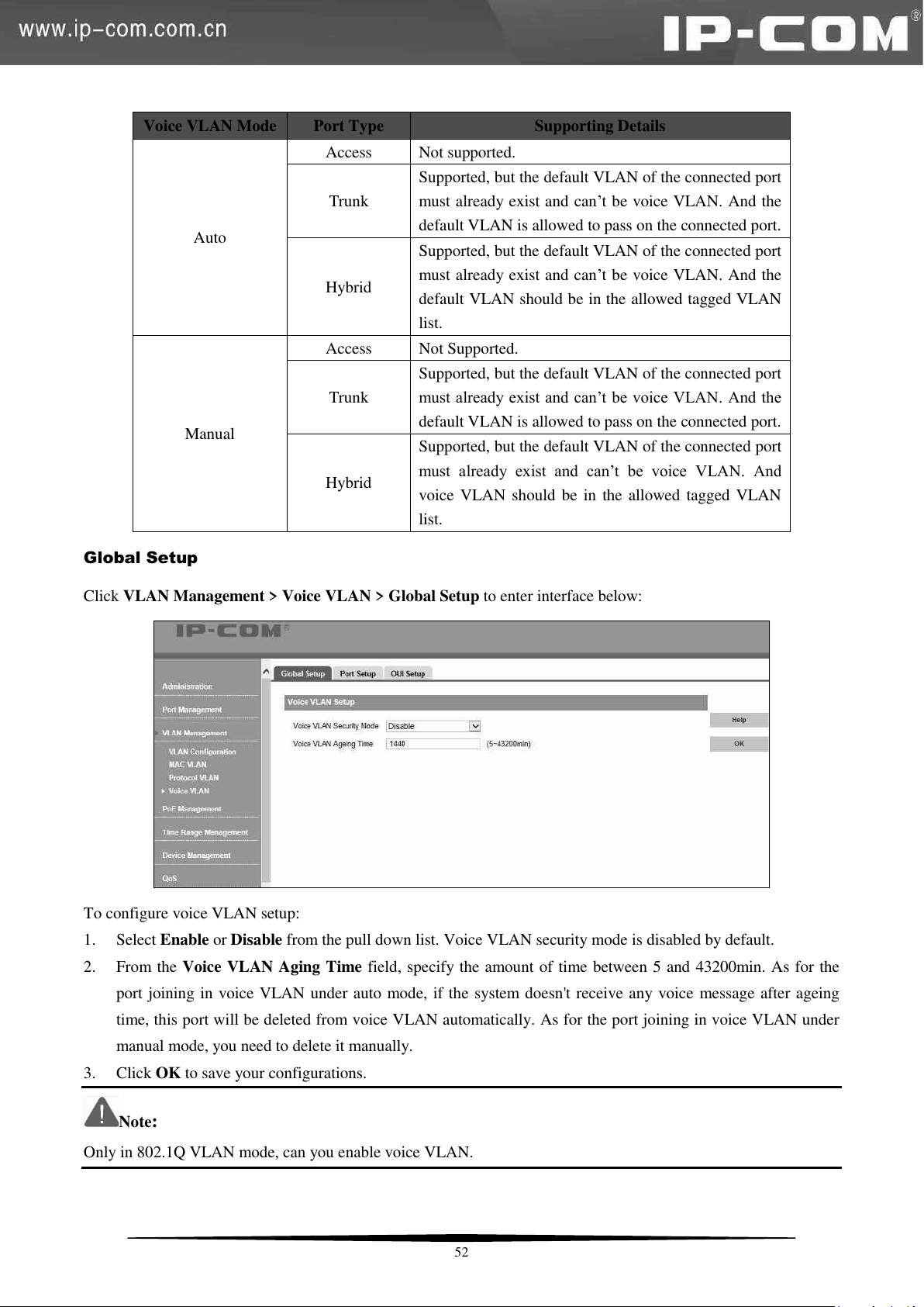
Voice VLAN Mode
Port Type
Supporting Details
Auto
Access
Not supported.
Trunk
Supported, but the default VLAN of the connected port
must already exist and can’t be voice VLAN. And the
default VLAN is allowed to pass on the connected port.
Hybrid
Supported, but the default VLAN of the connected port
must already exist and can’t be voice VLAN. And the
default VLAN should be in the allowed tagged VLAN
list.
Manual
Access
Not Supported.
Trunk
Supported, but the default VLAN of the connected port
must already exist and can’t be voice VLAN. And the
default VLAN is allowed to pass on the connected port.
Hybrid
Supported, but the default VLAN of the connected port
must already exist and can’t be voice VLAN. And
voice VLAN should be in the allowed tagged VLAN
list.
Global Setup
Click VLAN Management > Voice VLAN > Global Setup to enter interface below:
To configure voice VLAN setup:
1. Select Enable or Disable from the pull down list. Voice VLAN security mode is disabled by default.
2. From the Voice VLAN Aging Time field, specify the amount of time between 5 and 43200min. As for the
port joining in voice VLAN under auto mode, if the system doesn't receive any voice message after ageing
time, this port will be deleted from voice VLAN automatically. As for the port joining in voice VLAN under
manual mode, you need to delete it manually.
3. Click OK to save your configurations.
Note:
Only in 802.1Q VLAN mode, can you enable voice VLAN.
52
Page 60
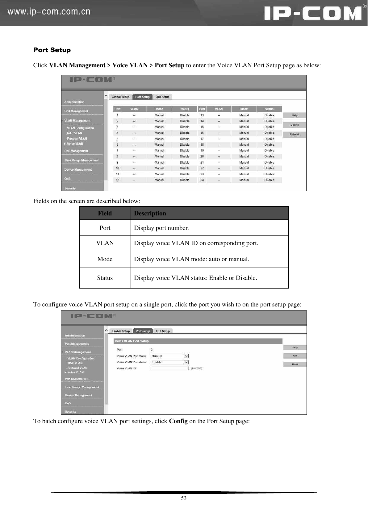
Field
Description
Port
Display port number.
VLAN
Display voice VLAN ID on corresponding port.
Mode
Display voice VLAN mode: auto or manual.
Status
Display voice VLAN status: Enable or Disable.
Port Setup
Click VLAN Management > Voice VLAN > Port Setup to enter the Voice VLAN Port Setup page as below:
Fields on the screen are described below:
To configure voice VLAN port setup on a single port, click the port you wish to on the port setup page:
To batch configure voice VLAN port settings, click Config on the Port Setup page:
53
Page 61
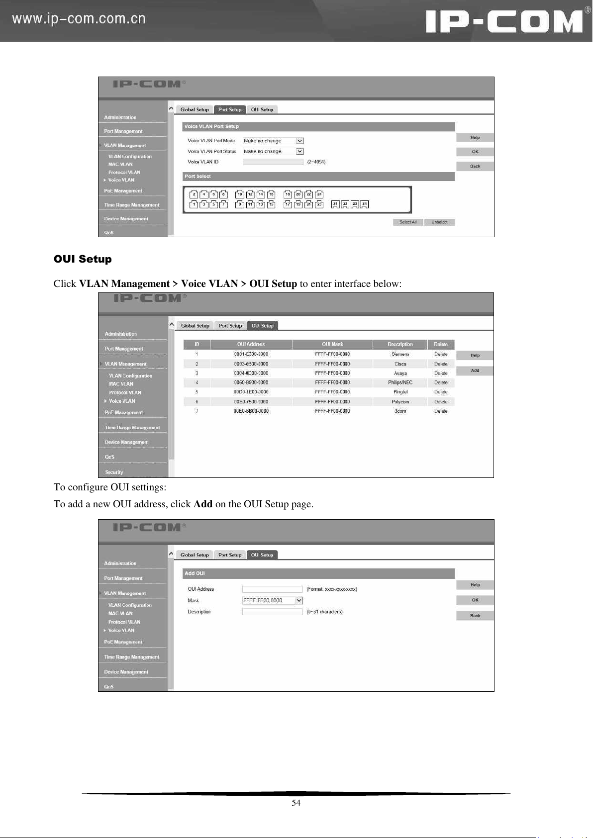
OUI Setup
Click VLAN Management > Voice VLAN > OUI Setup to enter interface below:
To configure OUI settings:
To add a new OUI address, click Add on the OUI Setup page.
54
Page 62
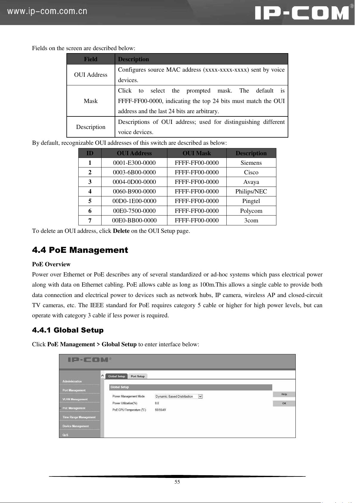
Field
Description
OUI Address
Configures source MAC address (xxxx-xxxx-xxxx) sent by voice
devices.
Mask
Click to select the prompted mask. The default is
FFFF-FF00-0000, indicating the top 24 bits must match the OUI
address and the last 24 bits are arbitrary.
Description
Descriptions of OUI address; used for distinguishing different
voice devices.
ID
OUI Address
OUI Mask
Description
1
0001-E300-0000
FFFF-FF00-0000
Siemens
2
0003-6B00-0000
FFFF-FF00-0000
Cisco
3
0004-0D00-0000
FFFF-FF00-0000
Avaya
4
0060-B900-0000
FFFF-FF00-0000
Philips/NEC
5
00D0-1E00-0000
FFFF-FF00-0000
Pingtel
6
00E0-7500-0000
FFFF-FF00-0000
Polycom
7
00E0-BB00-0000
FFFF-FF00-0000
3com
Fields on the screen are described below:
By default, recognizable OUI addresses of this switch are described as below:
To delete an OUI address, click Delete on the OUI Setup page.
4.4 PoE Management
PoE Overview
Power over Ethernet or PoE describes any of several standardized or ad-hoc systems which pass electrical power
along with data on Ethernet cabling. PoE allows cable as long as 100m.This allows a single cable to provide both
data connection and electrical power to devices such as network hubs, IP camera, wireless AP and closed-circuit
TV cameras, etc. The IEEE standard for PoE requires category 5 cable or higher for high power levels, but can
operate with category 3 cable if less power is required.
4.4.1 Global Setup
Click PoE Management > Global Setup to enter interface below:
55
Page 63
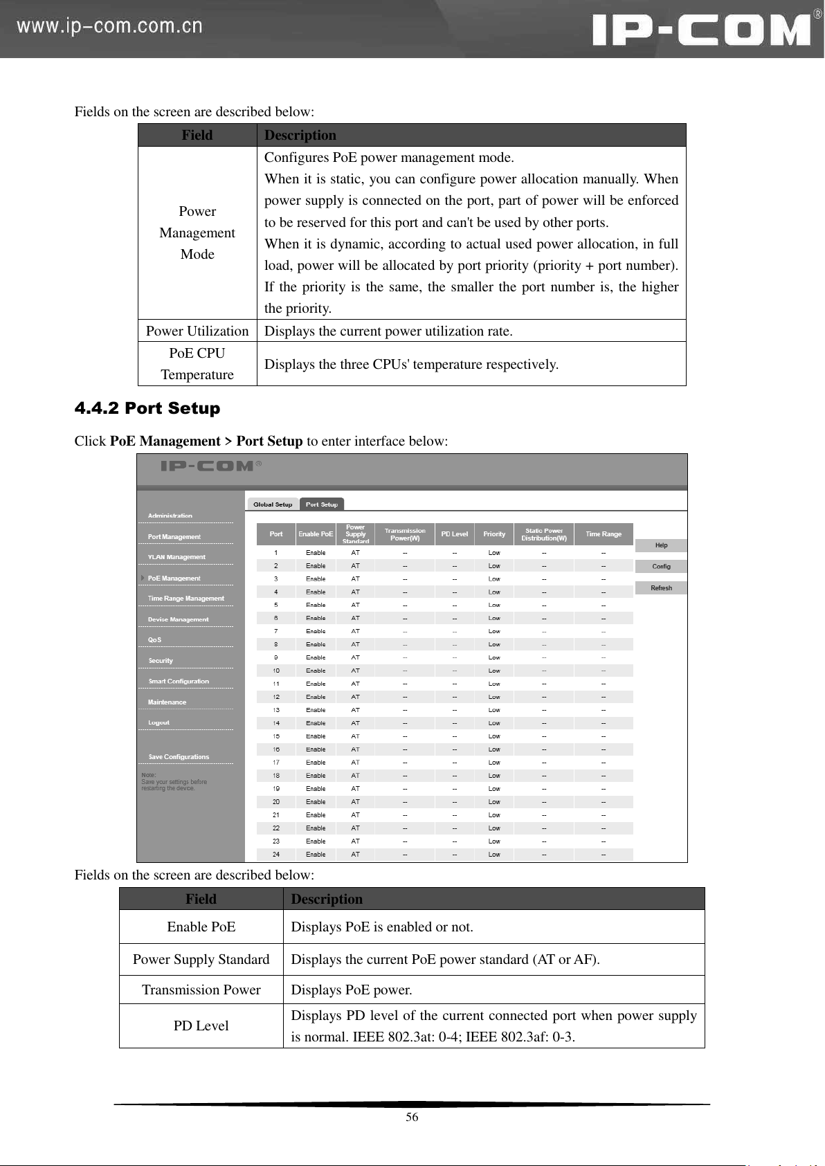
Field
Description
Power
Management
Mode
Configures PoE power management mode.
When it is static, you can configure power allocation manually. When
power supply is connected on the port, part of power will be enforced
to be reserved for this port and can't be used by other ports.
When it is dynamic, according to actual used power allocation, in full
load, power will be allocated by port priority (priority + port number).
If the priority is the same, the smaller the port number is, the higher
the priority.
Power Utilization
Displays the current power utilization rate.
PoE CPU
Temperature
Displays the three CPUs' temperature respectively.
Field
Description
Enable PoE
Displays PoE is enabled or not.
Power Supply Standard
Displays the current PoE power standard (AT or AF).
Transmission Power
Displays PoE power.
PD Level
Displays PD level of the current connected port when power supply
is normal. IEEE 802.3at: 0-4; IEEE 802.3af: 0-3.
Fields on the screen are described below:
4.4.2 Port Setup
Click PoE Management > Port Setup to enter interface below:
Fields on the screen are described below:
56
Page 64
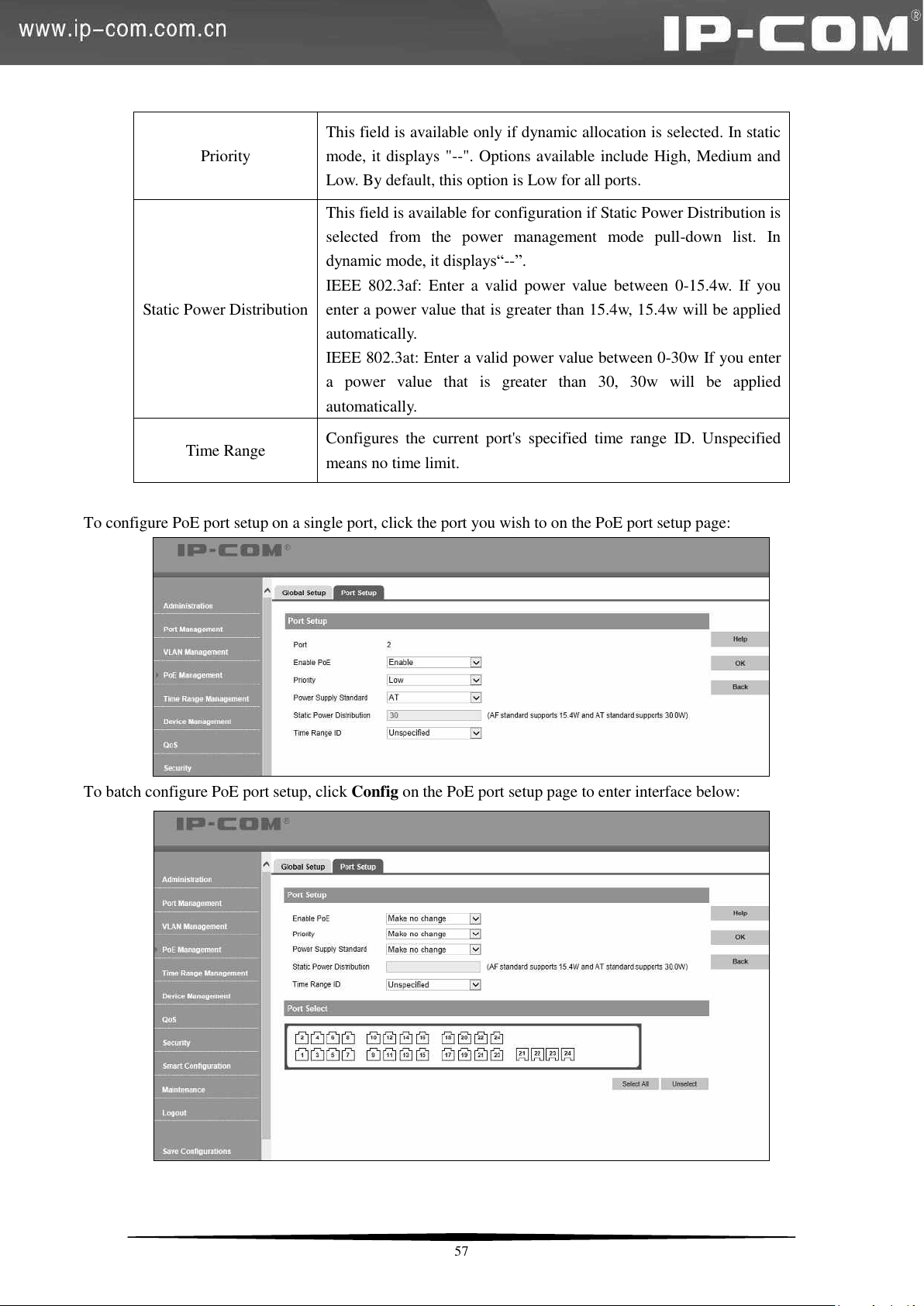
Priority
This field is available only if dynamic allocation is selected. In static
mode, it displays "--". Options available include High, Medium and
Low. By default, this option is Low for all ports.
Static Power Distribution
This field is available for configuration if Static Power Distribution is
selected from the power management mode pull-down list. In
dynamic mode, it displays―--‖.
IEEE 802.3af: Enter a valid power value between 0-15.4w. If you
enter a power value that is greater than 15.4w, 15.4w will be applied
automatically.
IEEE 802.3at: Enter a valid power value between 0-30w If you enter
a power value that is greater than 30, 30w will be applied
automatically.
Time Range
Configures the current port's specified time range ID. Unspecified
means no time limit.
To configure PoE port setup on a single port, click the port you wish to on the PoE port setup page:
To batch configure PoE port setup, click Config on the PoE port setup page to enter interface below:
57
Page 65
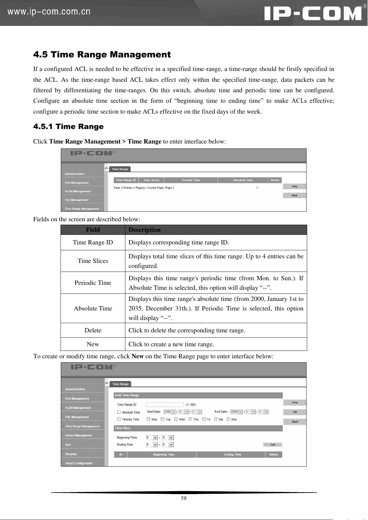
Field
Description
Time Range ID
Displays corresponding time range ID.
Time Slices
Displays total time slices of this time range. Up to 4 entries can be
configured.
Periodic Time
Displays this time range's periodic time (from Mon. to Sun.). If
Absolute Time is selected, this option will display ―--‖.
Absolute Time
Displays this time range's absolute time (from 2000, January 1st to
2035, December 31th.). If Periodic Time is selected, this option
will display ―--‖.
Delete
Click to delete the corresponding time range.
New
Click to create a new time range.
4.5 Time Range Management
If a configured ACL is needed to be effective in a specified time-range, a time-range should be firstly specified in
the ACL. As the time-range based ACL takes effect only within the specified time-range, data packets can be
filtered by differentiating the time-ranges. On this switch, absolute time and periodic time can be configured.
Configure an absolute time section in the form of ―beginning time to ending time‖ to make ACLs effective;
configure a periodic time section to make ACLs effective on the fixed days of the week.
4.5.1 Time Range
Click Time Range Management > Time Range to enter interface below:
Fields on the screen are described below:
To create or modify time range, click New on the Time Range page to enter interface below:
58
Page 66
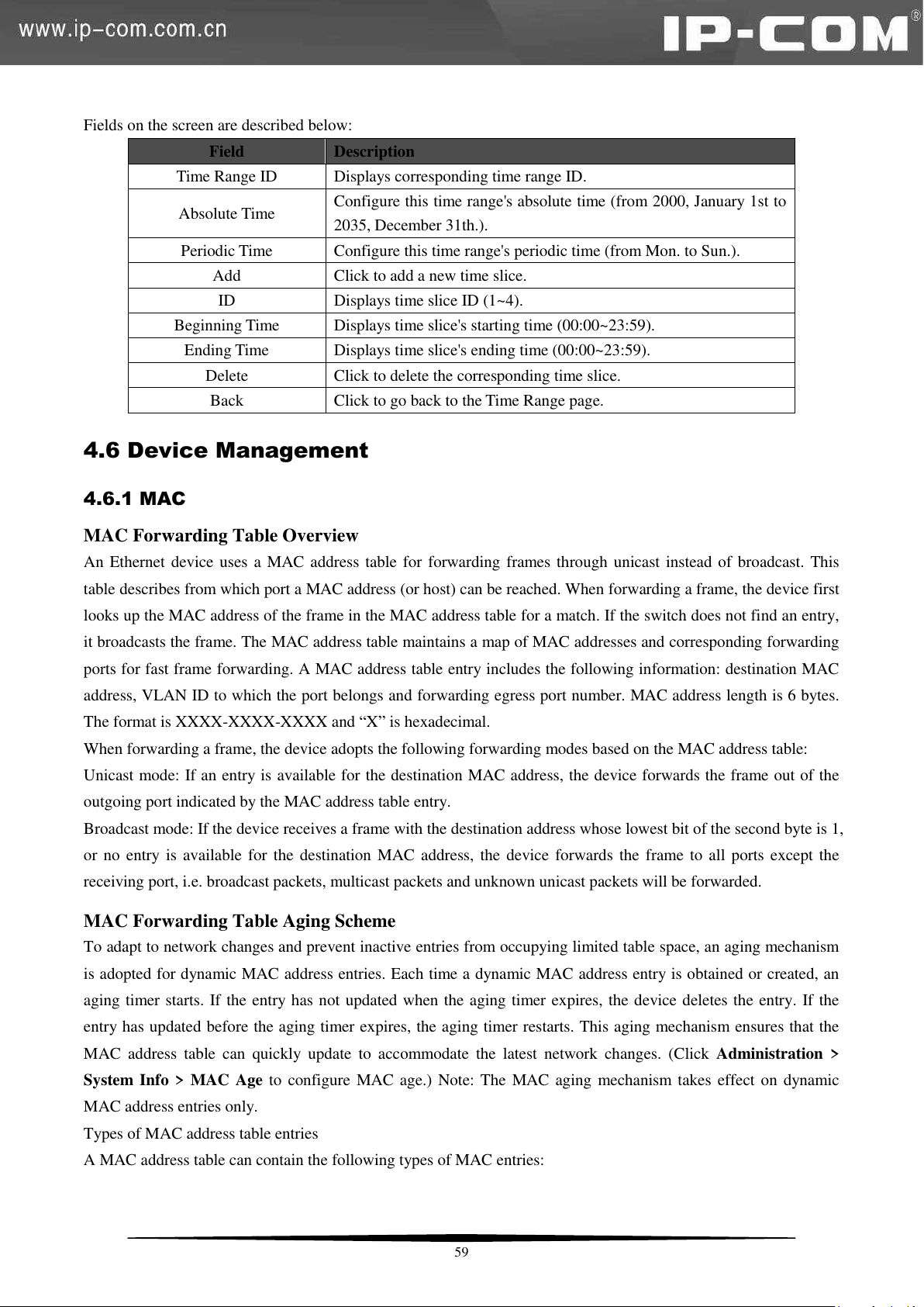
Fields on the screen are described below:
Field
Description
Time Range ID
Displays corresponding time range ID.
Absolute Time
Configure this time range's absolute time (from 2000, January 1st to
2035, December 31th.).
Periodic Time
Configure this time range's periodic time (from Mon. to Sun.).
Add
Click to add a new time slice.
ID
Displays time slice ID (1~4).
Beginning Time
Displays time slice's starting time (00:00~23:59).
Ending Time
Displays time slice's ending time (00:00~23:59).
Delete
Click to delete the corresponding time slice.
Back
Click to go back to the Time Range page.
4.6 Device Management
4.6.1 MAC
MAC Forwarding Table Overview
An Ethernet device uses a MAC address table for forwarding frames through unicast instead of broadcast. This
table describes from which port a MAC address (or host) can be reached. When forwarding a frame, the device first
looks up the MAC address of the frame in the MAC address table for a match. If the switch does not find an entry,
it broadcasts the frame. The MAC address table maintains a map of MAC addresses and corresponding forwarding
ports for fast frame forwarding. A MAC address table entry includes the following information: destination MAC
address, VLAN ID to which the port belongs and forwarding egress port number. MAC address length is 6 bytes.
The format is XXXX-XXXX-XXXX and ―X‖ is hexadecimal.
When forwarding a frame, the device adopts the following forwarding modes based on the MAC address table:
Unicast mode: If an entry is available for the destination MAC address, the device forwards the frame out of the
outgoing port indicated by the MAC address table entry.
Broadcast mode: If the device receives a frame with the destination address whose lowest bit of the second byte is 1,
or no entry is available for the destination MAC address, the device forwards the frame to all ports except the
receiving port, i.e. broadcast packets, multicast packets and unknown unicast packets will be forwarded.
MAC Forwarding Table Aging Scheme
To adapt to network changes and prevent inactive entries from occupying limited table space, an aging mechanism
is adopted for dynamic MAC address entries. Each time a dynamic MAC address entry is obtained or created, an
aging timer starts. If the entry has not updated when the aging timer expires, the device deletes the entry. If the
entry has updated before the aging timer expires, the aging timer restarts. This aging mechanism ensures that the
MAC address table can quickly update to accommodate the latest network changes. (Click Administration >
System Info > MAC Age to configure MAC age.) Note: The MAC aging mechanism takes effect on dynamic
MAC address entries only.
Types of MAC address table entries
A MAC address table can contain the following types of MAC entries:
59
Page 67
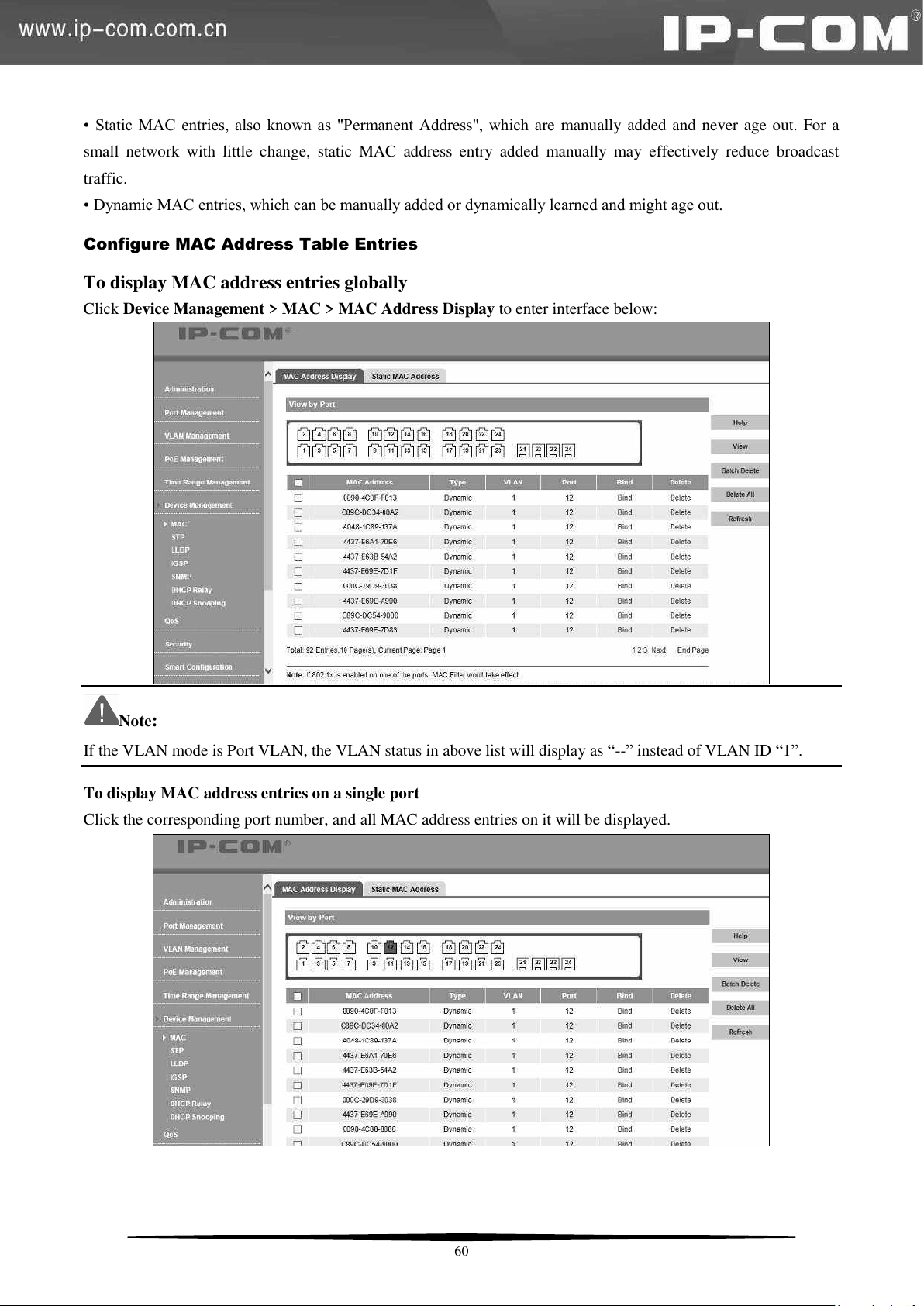
• Static MAC entries, also known as "Permanent Address", which are manually added and never age out. For a
small network with little change, static MAC address entry added manually may effectively reduce broadcast
traffic.
• Dynamic MAC entries, which can be manually added or dynamically learned and might age out.
Configure MAC Address Table Entries
To display MAC address entries globally
Click Device Management > MAC > MAC Address Display to enter interface below:
Note:
If the VLAN mode is Port VLAN, the VLAN status in above list will display as ―--‖ instead of VLAN ID ―1‖.
To display MAC address entries on a single port
Click the corresponding port number, and all MAC address entries on it will be displayed.
60
Page 68
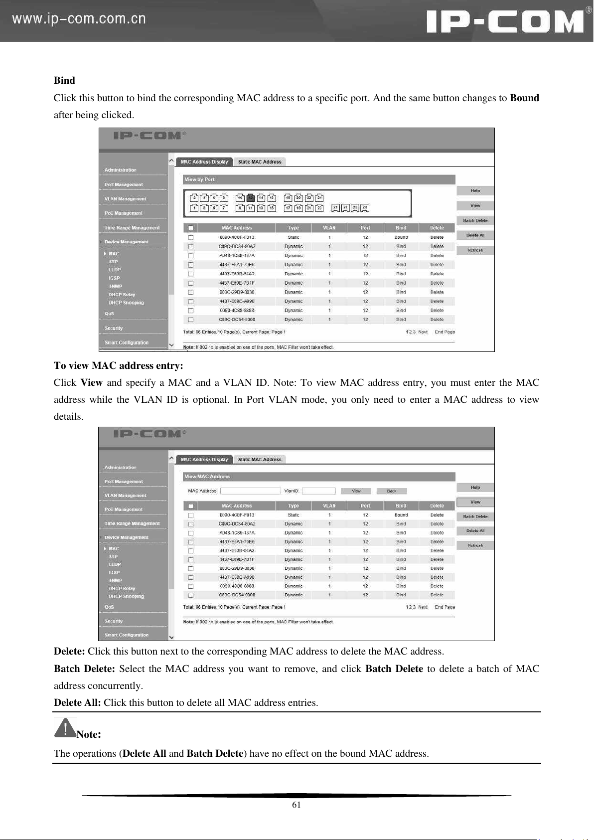
Bind
Click this button to bind the corresponding MAC address to a specific port. And the same button changes to Bound
after being clicked.
To view MAC address entry:
Click View and specify a MAC and a VLAN ID. Note: To view MAC address entry, you must enter the MAC
address while the VLAN ID is optional. In Port VLAN mode, you only need to enter a MAC address to view
details.
Delete: Click this button next to the corresponding MAC address to delete the MAC address.
Batch Delete: Select the MAC address you want to remove, and click Batch Delete to delete a batch of MAC
address concurrently.
Delete All: Click this button to delete all MAC address entries.
Note:
The operations (Delete All and Batch Delete) have no effect on the bound MAC address.
61
Page 69
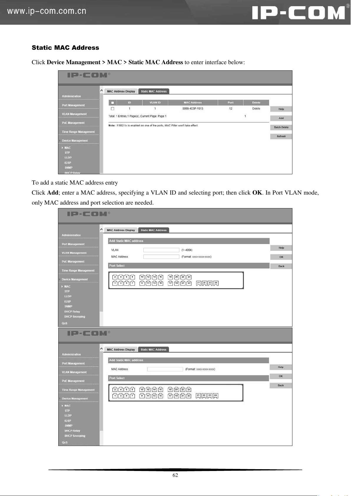
Static MAC Address
Click Device Management > MAC > Static MAC Address to enter interface below:
To add a static MAC address entry
Click Add; enter a MAC address, specifying a VLAN ID and selecting port; then click OK. In Port VLAN mode,
only MAC address and port selection are needed.
62
Page 70
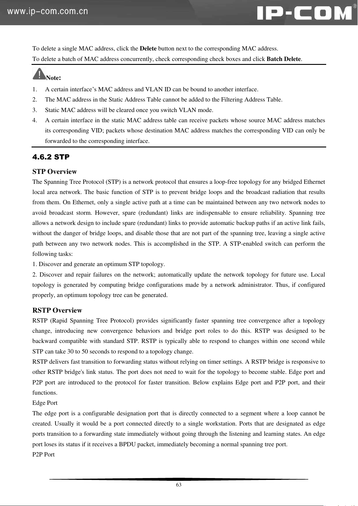
To delete a single MAC address, click the Delete button next to the corresponding MAC address.
To delete a batch of MAC address concurrently, check corresponding check boxes and click Batch Delete.
Note:
1. A certain interface’s MAC address and VLAN ID can be bound to another interface.
2. The MAC address in the Static Address Table cannot be added to the Filtering Address Table.
3. Static MAC address will be cleared once you switch VLAN mode.
4. A certain interface in the static MAC address table can receive packets whose source MAC address matches
its corresponding VID; packets whose destination MAC address matches the corresponding VID can only be
forwarded to the corresponding interface.
4.6.2 STP
STP Overview
The Spanning Tree Protocol (STP) is a network protocol that ensures a loop-free topology for any bridged Ethernet
local area network. The basic function of STP is to prevent bridge loops and the broadcast radiation that results
from them. On Ethernet, only a single active path at a time can be maintained between any two network nodes to
avoid broadcast storm. However, spare (redundant) links are indispensable to ensure reliability. Spanning tree
allows a network design to include spare (redundant) links to provide automatic backup paths if an active link fails,
without the danger of bridge loops, and disable those that are not part of the spanning tree, leaving a single active
path between any two network nodes. This is accomplished in the STP. A STP-enabled switch can perform the
following tasks:
1. Discover and generate an optimum STP topology.
2. Discover and repair failures on the network; automatically update the network topology for future use. Local
topology is generated by computing bridge configurations made by a network administrator. Thus, if configured
properly, an optimum topology tree can be generated.
RSTP Overview
RSTP (Rapid Spanning Tree Protocol) provides significantly faster spanning tree convergence after a topology
change, introducing new convergence behaviors and bridge port roles to do this. RSTP was designed to be
backward compatible with standard STP. RSTP is typically able to respond to changes within one second while
STP can take 30 to 50 seconds to respond to a topology change.
RSTP delivers fast transition to forwarding status without relying on timer settings. A RSTP bridge is responsive to
other RSTP bridge's link status. The port does not need to wait for the topology to become stable. Edge port and
P2P port are introduced to the protocol for faster transition. Below explains Edge port and P2P port, and their
functions.
Edge Port
The edge port is a configurable designation port that is directly connected to a segment where a loop cannot be
created. Usually it would be a port connected directly to a single workstation. Ports that are designated as edge
ports transition to a forwarding state immediately without going through the listening and learning states. An edge
port loses its status if it receives a BPDU packet, immediately becoming a normal spanning tree port.
P2P Port
63
Page 71
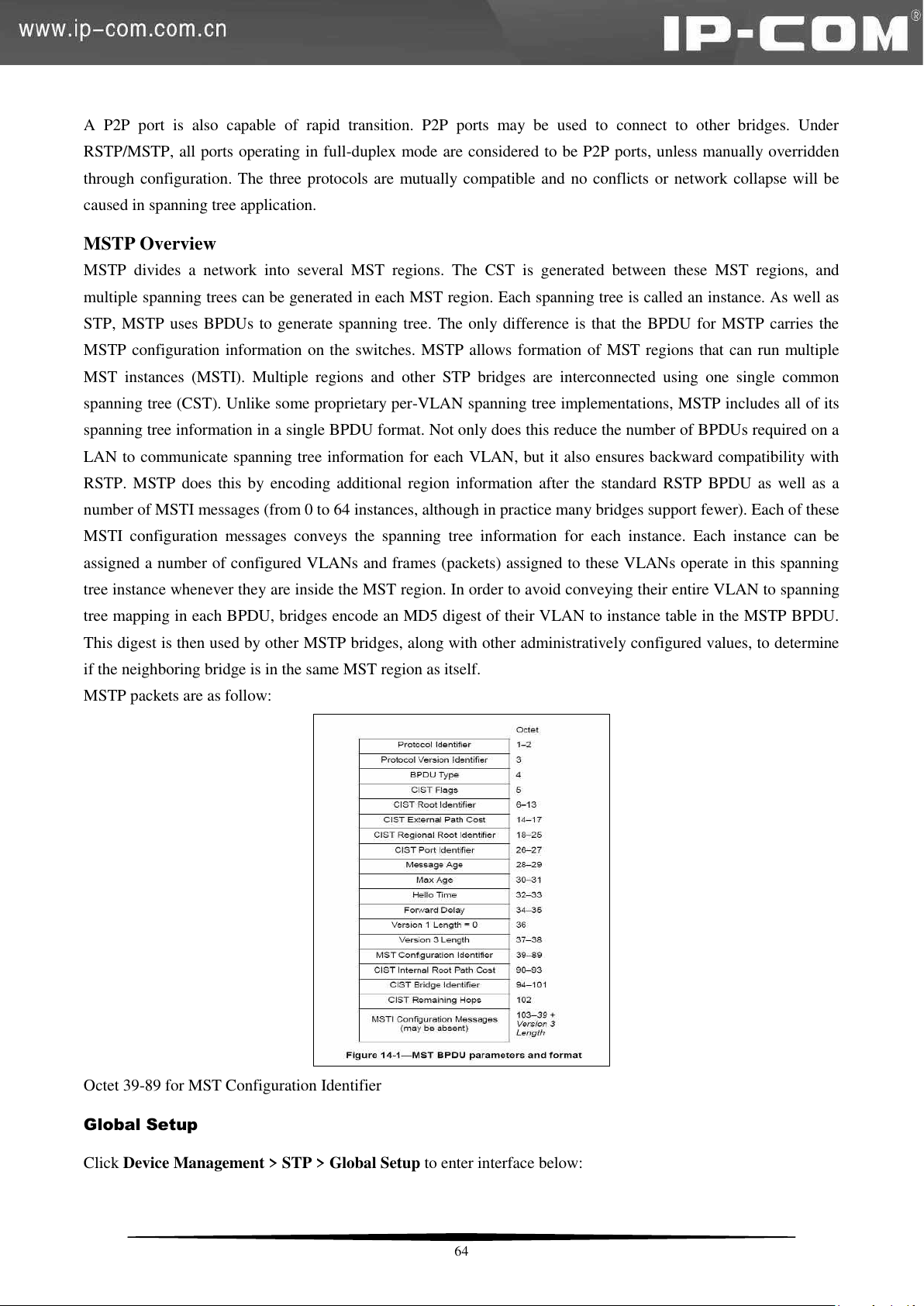
A P2P port is also capable of rapid transition. P2P ports may be used to connect to other bridges. Under
RSTP/MSTP, all ports operating in full-duplex mode are considered to be P2P ports, unless manually overridden
through configuration. The three protocols are mutually compatible and no conflicts or network collapse will be
caused in spanning tree application.
MSTP Overview
MSTP divides a network into several MST regions. The CST is generated between these MST regions, and
multiple spanning trees can be generated in each MST region. Each spanning tree is called an instance. As well as
STP, MSTP uses BPDUs to generate spanning tree. The only difference is that the BPDU for MSTP carries the
MSTP configuration information on the switches. MSTP allows formation of MST regions that can run multiple
MST instances (MSTI). Multiple regions and other STP bridges are interconnected using one single common
spanning tree (CST). Unlike some proprietary per-VLAN spanning tree implementations, MSTP includes all of its
spanning tree information in a single BPDU format. Not only does this reduce the number of BPDUs required on a
LAN to communicate spanning tree information for each VLAN, but it also ensures backward compatibility with
RSTP. MSTP does this by encoding additional region information after the standard RSTP BPDU as well as a
number of MSTI messages (from 0 to 64 instances, although in practice many bridges support fewer). Each of these
MSTI configuration messages conveys the spanning tree information for each instance. Each instance can be
assigned a number of configured VLANs and frames (packets) assigned to these VLANs operate in this spanning
tree instance whenever they are inside the MST region. In order to avoid conveying their entire VLAN to spanning
tree mapping in each BPDU, bridges encode an MD5 digest of their VLAN to instance table in the MSTP BPDU.
This digest is then used by other MSTP bridges, along with other administratively configured values, to determine
if the neighboring bridge is in the same MST region as itself.
MSTP packets are as follow:
Octet 39-89 for MST Configuration Identifier
Global Setup
Click Device Management > STP > Global Setup to enter interface below:
64
Page 72
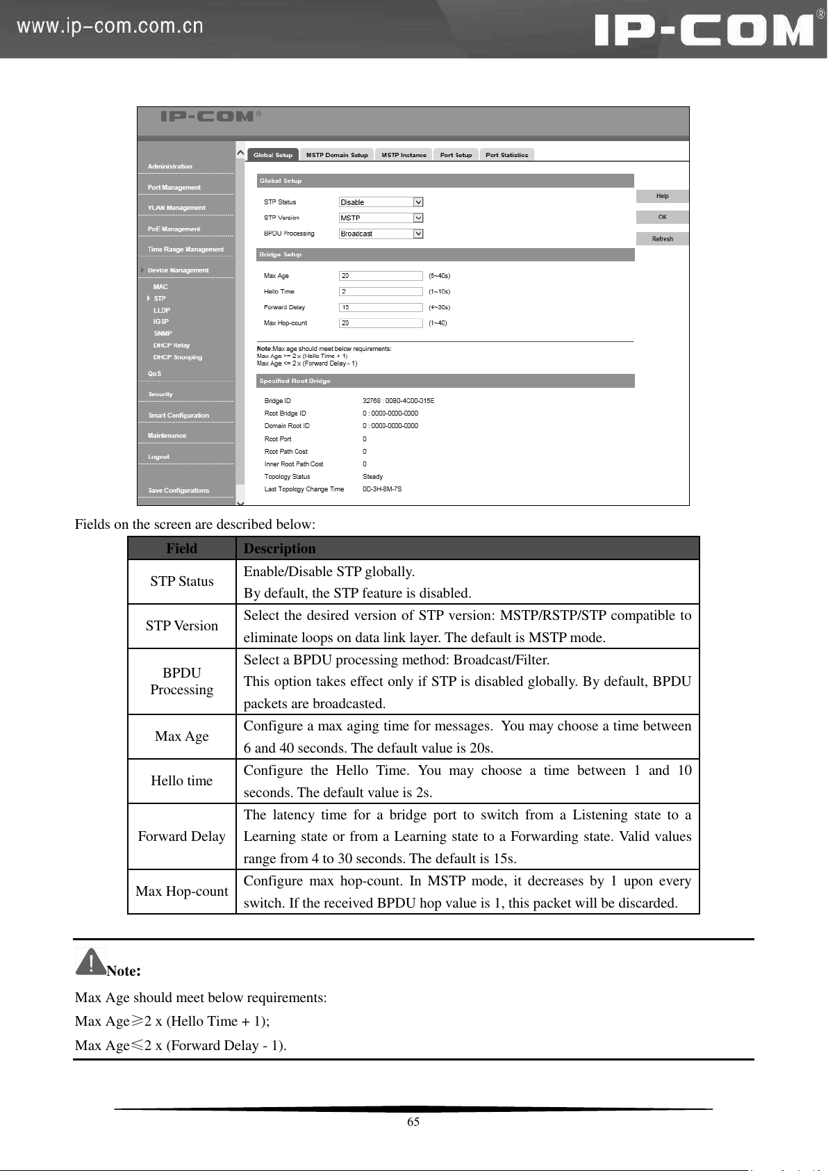
Field
Description
STP Status
Enable/Disable STP globally.
By default, the STP feature is disabled.
STP Version
Select the desired version of STP version: MSTP/RSTP/STP compatible to
eliminate loops on data link layer. The default is MSTP mode.
BPDU
Processing
Select a BPDU processing method: Broadcast/Filter.
This option takes effect only if STP is disabled globally. By default, BPDU
packets are broadcasted.
Max Age
Configure a max aging time for messages. You may choose a time between
6 and 40 seconds. The default value is 20s.
Hello time
Configure the Hello Time. You may choose a time between 1 and 10
seconds. The default value is 2s.
Forward Delay
The latency time for a bridge port to switch from a Listening state to a
Learning state or from a Learning state to a Forwarding state. Valid values
range from 4 to 30 seconds. The default is 15s.
Max Hop-count
Configure max hop-count. In MSTP mode, it decreases by 1 upon every
switch. If the received BPDU hop value is 1, this packet will be discarded.
Fields on the screen are described below:
Note:
Max Age should meet below requirements:
Max Age≥2 x (Hello Time + 1);
Max Age≤2 x (Forward Delay - 1).
65
Page 73
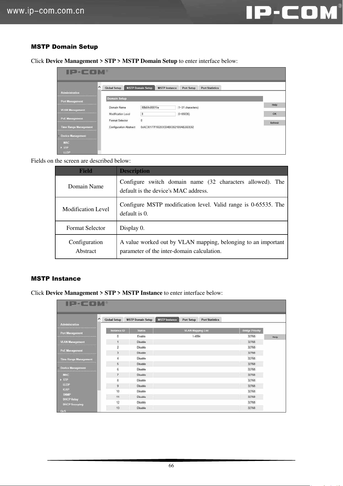
Field
Description
Domain Name
Configure switch domain name (32 characters allowed). The
default is the device's MAC address.
Modification Level
Configure MSTP modification level. Valid range is 0-65535. The
default is 0.
Format Selector
Display 0.
Configuration
Abstract
A value worked out by VLAN mapping, belonging to an important
parameter of the inter-domain calculation.
MSTP Domain Setup
Click Device Management > STP > MSTP Domain Setup to enter interface below:
Fields on the screen are described below:
MSTP Instance
Click Device Management > STP > MSTP Instance to enter interface below:
66
Page 74
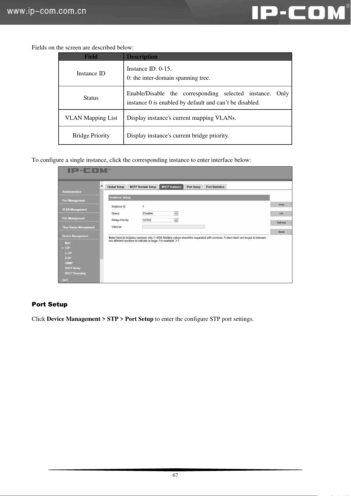
Field
Description
Instance ID
Instance ID: 0-15.
0: the inter-domain spanning tree.
Status
Enable/Disable the corresponding selected instance. Only
instance 0 is enabled by default and can’t be disabled.
VLAN Mapping List
Display instance's current mapping VLANs.
Bridge Priority
Display instance's current bridge priority.
Fields on the screen are described below:
To configure a single instance, click the corresponding instance to enter interface below:
Port Setup
Click Device Management > STP > Port Setup to enter the configure STP port settings.
67
Page 75
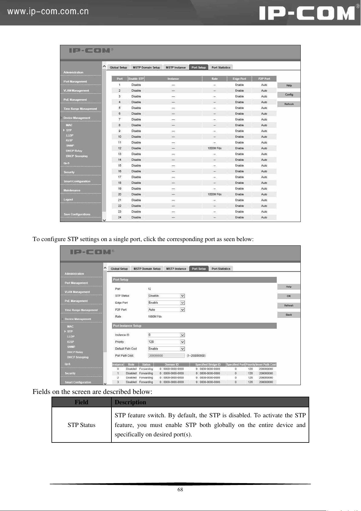
Field
Description
STP Status
STP feature switch. By default, the STP is disabled. To activate the STP
feature, you must enable STP both globally on the entire device and
specifically on desired port(s).
To configure STP settings on a single port, click the corresponding port as seen below:
Fields on the screen are described below:
68
Page 76
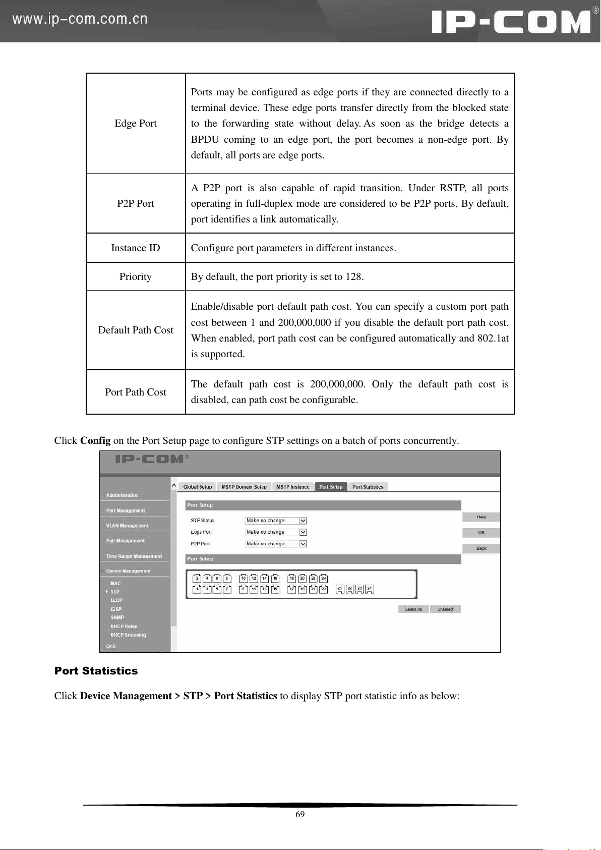
Edge Port
Ports may be configured as edge ports if they are connected directly to a
terminal device. These edge ports transfer directly from the blocked state
to the forwarding state without delay. As soon as the bridge detects a
BPDU coming to an edge port, the port becomes a non-edge port. By
default, all ports are edge ports.
P2P Port
A P2P port is also capable of rapid transition. Under RSTP, all ports
operating in full-duplex mode are considered to be P2P ports. By default,
port identifies a link automatically.
Instance ID
Configure port parameters in different instances.
Priority
By default, the port priority is set to 128.
Default Path Cost
Enable/disable port default path cost. You can specify a custom port path
cost between 1 and 200,000,000 if you disable the default port path cost.
When enabled, port path cost can be configured automatically and 802.1at
is supported.
Port Path Cost
The default path cost is 200,000,000. Only the default path cost is
disabled, can path cost be configurable.
Click Config on the Port Setup page to configure STP settings on a batch of ports concurrently.
Port Statistics
Click Device Management > STP > Port Statistics to display STP port statistic info as below:
69
Page 77
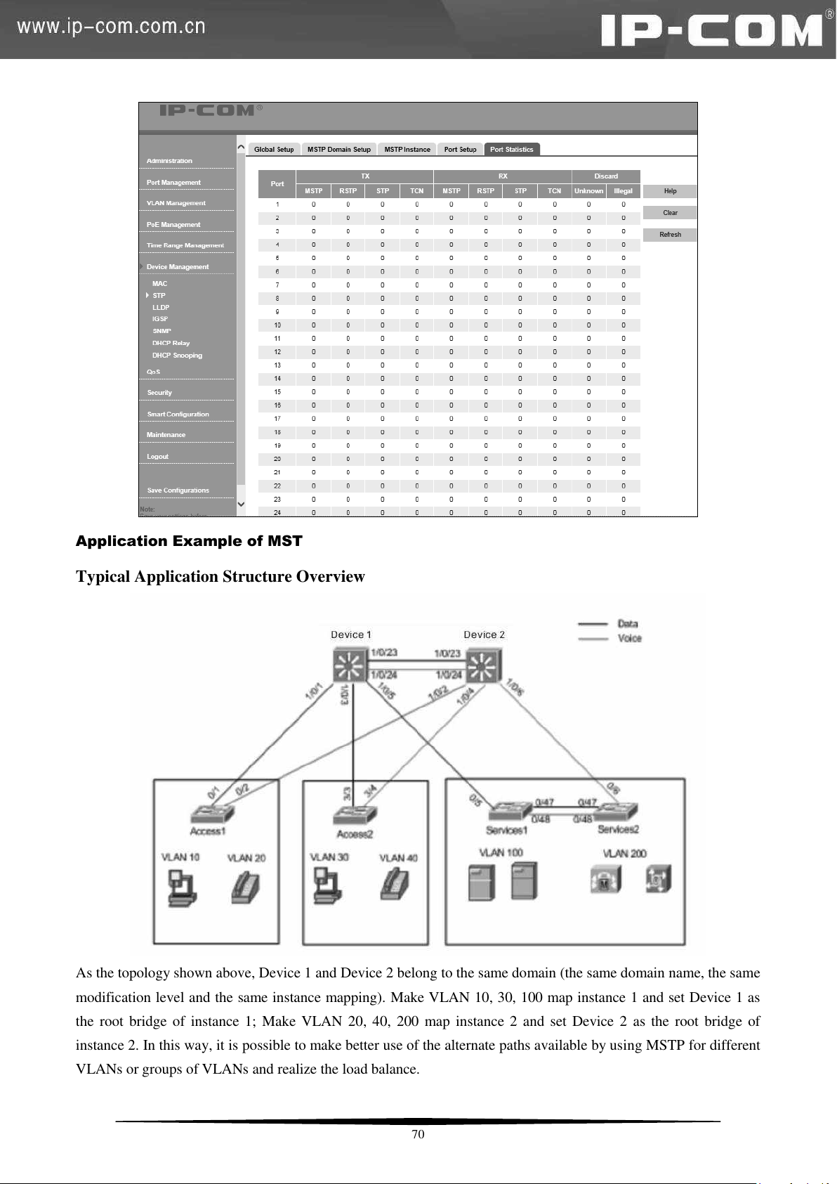
Application Example of MST
Typical Application Structure Overview
As the topology shown above, Device 1 and Device 2 belong to the same domain (the same domain name, the same
modification level and the same instance mapping). Make VLAN 10, 30, 100 map instance 1 and set Device 1 as
the root bridge of instance 1; Make VLAN 20, 40, 200 map instance 2 and set Device 2 as the root bridge of
instance 2. In this way, it is possible to make better use of the alternate paths available by using MSTP for different
VLANs or groups of VLANs and realize the load balance.
70
Page 78
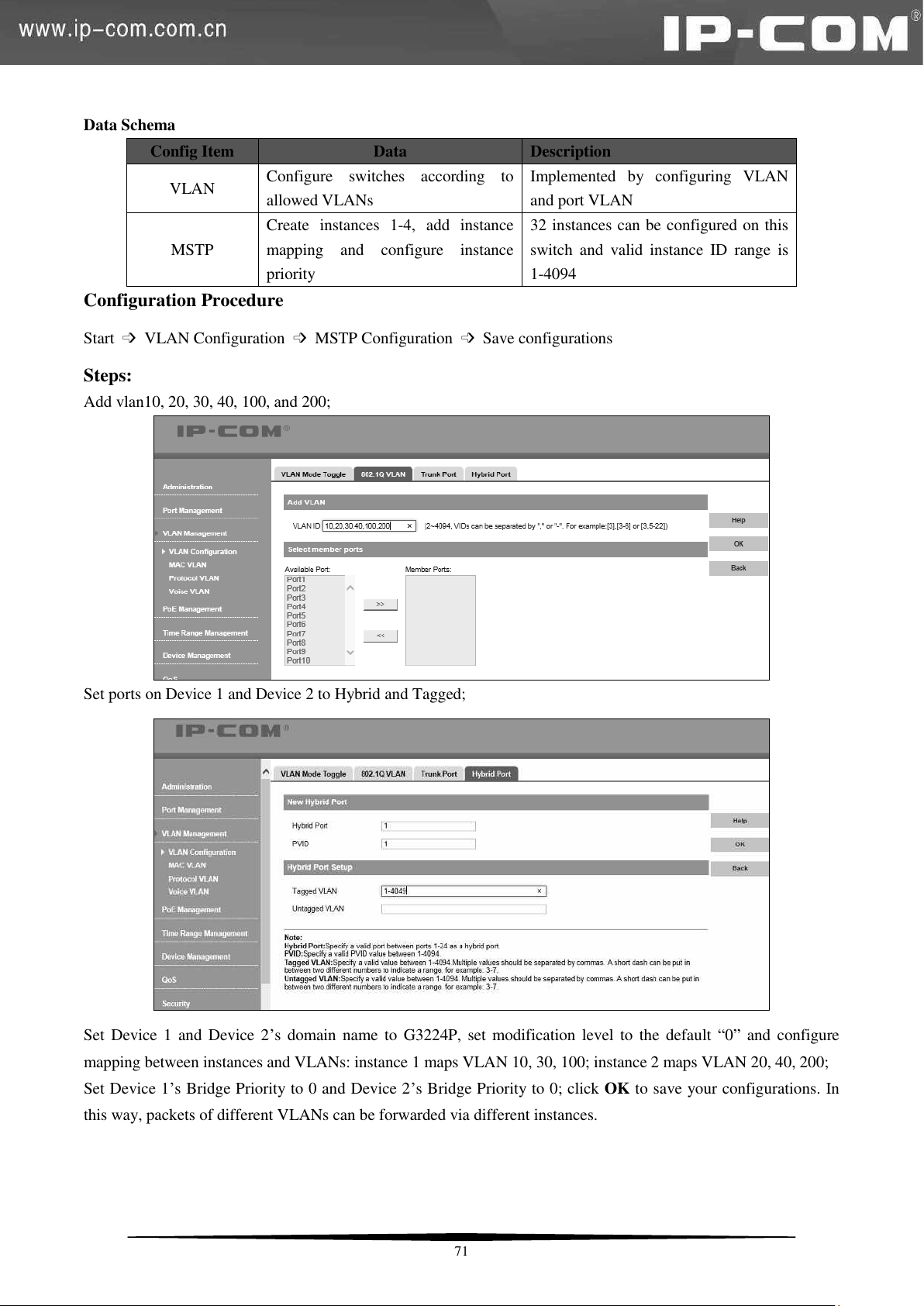
Config Item
Data
Description
VLAN
Configure switches according to
allowed VLANs
Implemented by configuring VLAN
and port VLAN
MSTP
Create instances 1-4, add instance
mapping and configure instance
priority
32 instances can be configured on this
switch and valid instance ID range is
1-4094
Data Schema
Configuration Procedure
Start ➩ VLAN Configuration ➩ MSTP Configuration ➩ Save configurations
Steps:
Add vlan10, 20, 30, 40, 100, and 200;
Set ports on Device 1 and Device 2 to Hybrid and Tagged;
Set Device 1 and Device 2’s domain name to G3224P, set modification level to the default ―0‖ and configure
mapping between instances and VLANs: instance 1 maps VLAN 10, 30, 100; instance 2 maps VLAN 20, 40, 200;
Set Device 1’s Bridge Priority to 0 and Device 2’s Bridge Priority to 0; click OK to save your configurations. In
this way, packets of different VLANs can be forwarded via different instances.
71
Page 79
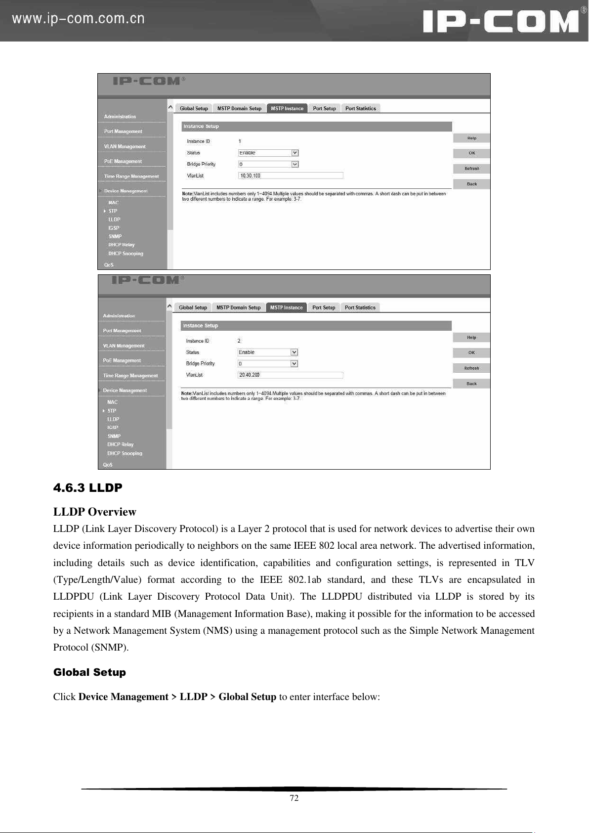
4.6.3 LLDP
LLDP Overview
LLDP (Link Layer Discovery Protocol) is a Layer 2 protocol that is used for network devices to advertise their own
device information periodically to neighbors on the same IEEE 802 local area network. The advertised information,
including details such as device identification, capabilities and configuration settings, is represented in TLV
(Type/Length/Value) format according to the IEEE 802.1ab standard, and these TLVs are encapsulated in
LLDPDU (Link Layer Discovery Protocol Data Unit). The LLDPDU distributed via LLDP is stored by its
recipients in a standard MIB (Management Information Base), making it possible for the information to be accessed
by a Network Management System (NMS) using a management protocol such as the Simple Network Management
Protocol (SNMP).
Global Setup
Click Device Management > LLDP > Global Setup to enter interface below:
72
Page 80
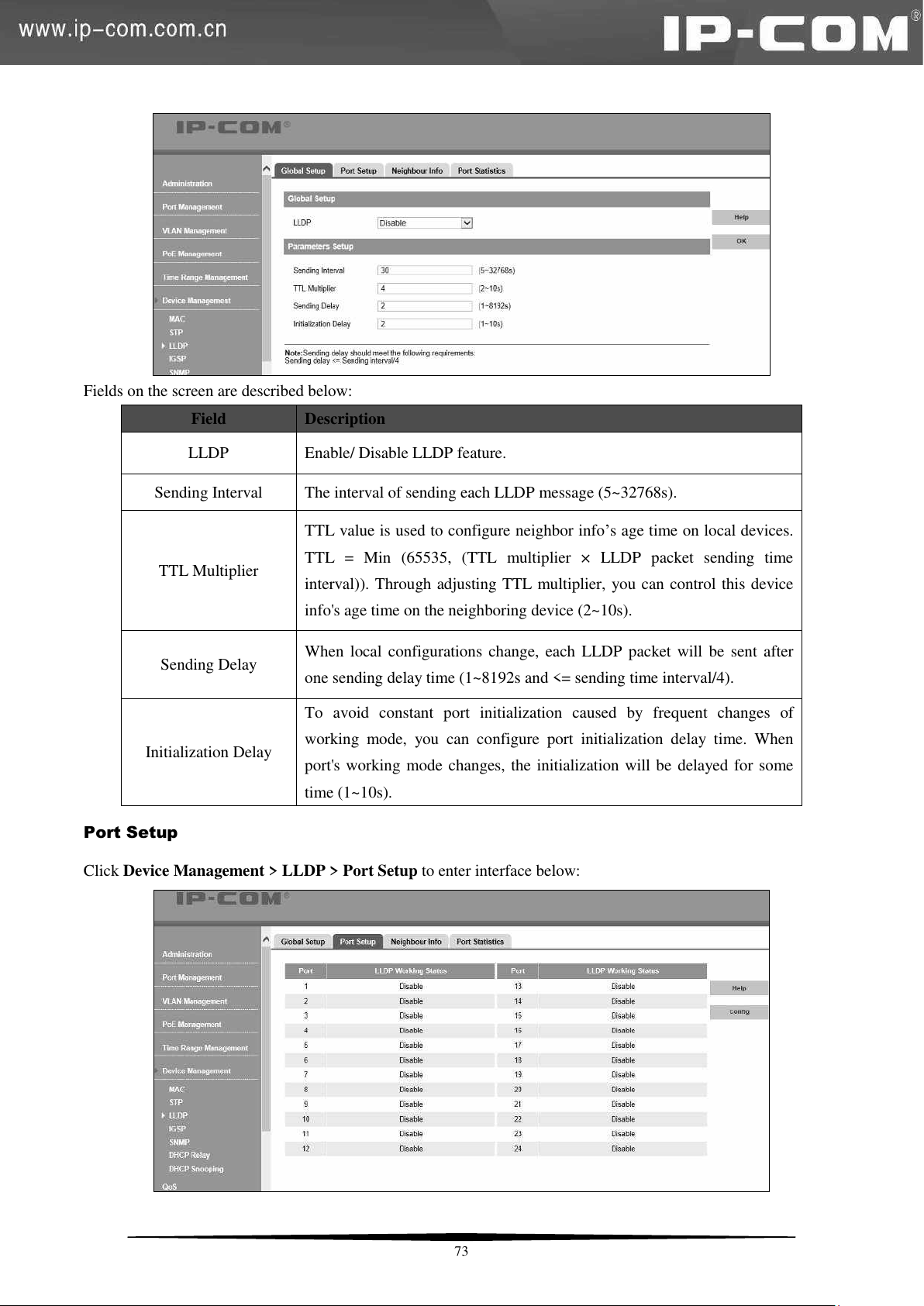
Fields on the screen are described below:
Field
Description
LLDP
Enable/ Disable LLDP feature.
Sending Interval
The interval of sending each LLDP message (5~32768s).
TTL Multiplier
TTL value is used to configure neighbor info’s age time on local devices.
TTL = Min (65535, (TTL multiplier × LLDP packet sending time
interval)). Through adjusting TTL multiplier, you can control this device
info's age time on the neighboring device (2~10s).
Sending Delay
When local configurations change, each LLDP packet will be sent after
one sending delay time (1~8192s and <= sending time interval/4).
Initialization Delay
To avoid constant port initialization caused by frequent changes of
working mode, you can configure port initialization delay time. When
port's working mode changes, the initialization will be delayed for some
time (1~10s).
Port Setup
Click Device Management > LLDP > Port Setup to enter interface below:
73
Page 81
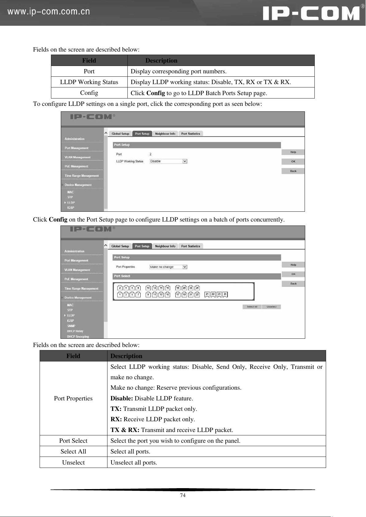
Field
Description
Port
Display corresponding port numbers.
LLDP Working Status
Display LLDP working status: Disable, TX, RX or TX & RX.
Config
Click Config to go to LLDP Batch Ports Setup page.
Field
Description
Port Properties
Select LLDP working status: Disable, Send Only, Receive Only, Transmit or
make no change.
Make no change: Reserve previous configurations.
Disable: Disable LLDP feature.
TX: Transmit LLDP packet only.
RX: Receive LLDP packet only.
TX & RX: Transmit and receive LLDP packet.
Port Select
Select the port you wish to configure on the panel.
Select All
Select all ports.
Unselect
Unselect all ports.
Fields on the screen are described below:
To configure LLDP settings on a single port, click the corresponding port as seen below:
Click Config on the Port Setup page to configure LLDP settings on a batch of ports concurrently.
Fields on the screen are described below:
74
Page 82
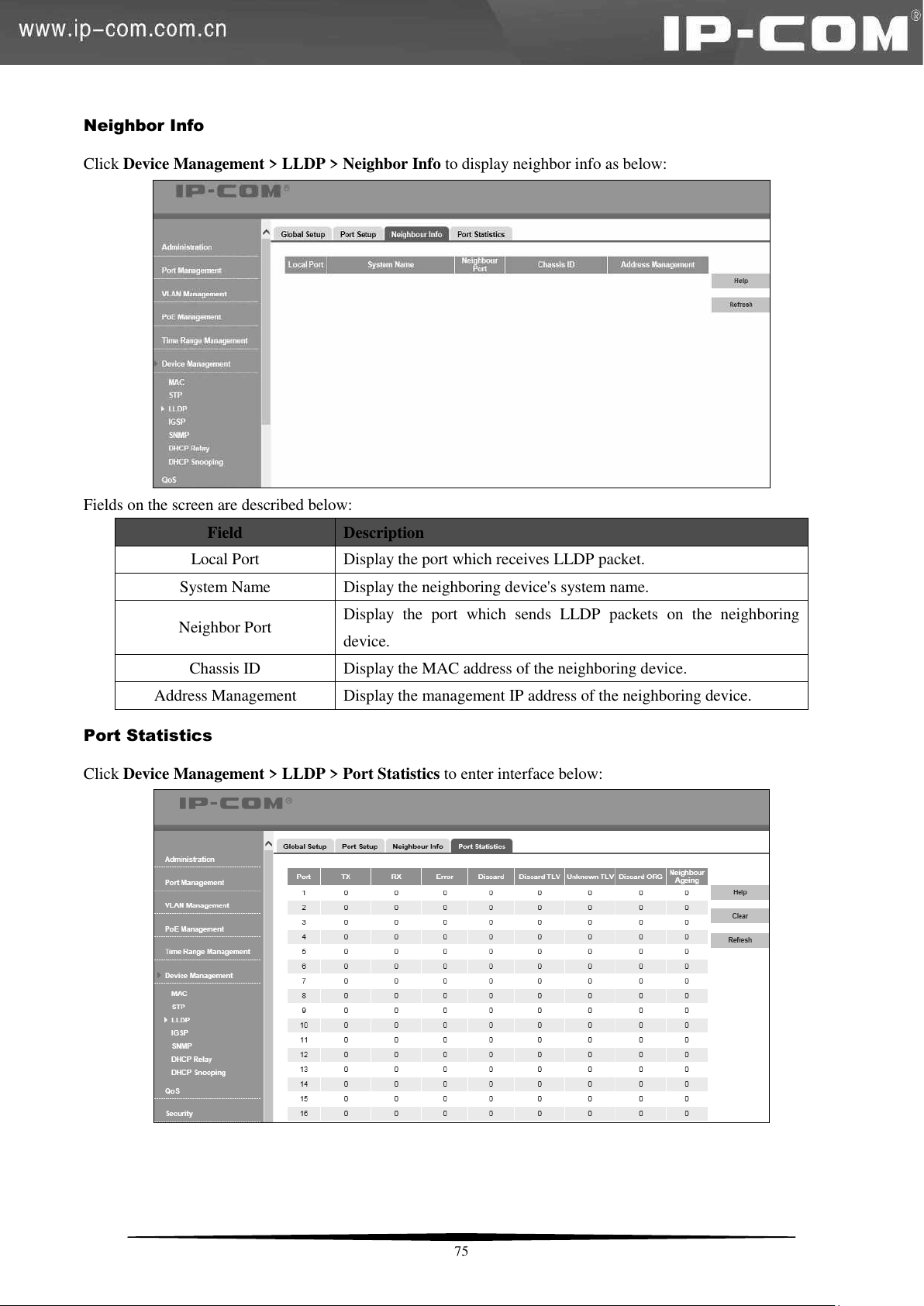
Field
Description
Local Port
Display the port which receives LLDP packet.
System Name
Display the neighboring device's system name.
Neighbor Port
Display the port which sends LLDP packets on the neighboring
device.
Chassis ID
Display the MAC address of the neighboring device.
Address Management
Display the management IP address of the neighboring device.
Neighbor Info
Click Device Management > LLDP > Neighbor Info to display neighbor info as below:
Fields on the screen are described below:
Port Statistics
Click Device Management > LLDP > Port Statistics to enter interface below:
75
Page 83
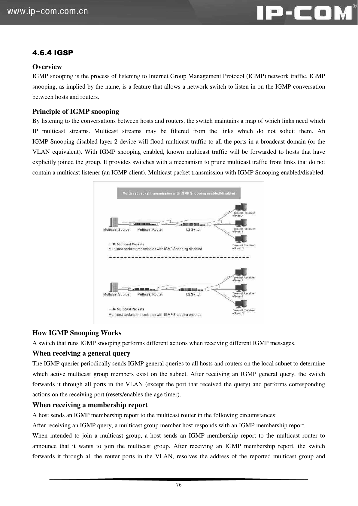
4.6.4 IGSP
Overview
IGMP snooping is the process of listening to Internet Group Management Protocol (IGMP) network traffic. IGMP
snooping, as implied by the name, is a feature that allows a network switch to listen in on the IGMP conversation
between hosts and routers.
Principle of IGMP snooping
By listening to the conversations between hosts and routers, the switch maintains a map of which links need which
IP multicast streams. Multicast streams may be filtered from the links which do not solicit them. An
IGMP-Snooping-disabled layer-2 device will flood multicast traffic to all the ports in a broadcast domain (or the
VLAN equivalent). With IGMP snooping enabled, known multicast traffic will be forwarded to hosts that have
explicitly joined the group. It provides switches with a mechanism to prune multicast traffic from links that do not
contain a multicast listener (an IGMP client). Multicast packet transmission with IGMP Snooping enabled/disabled:
How IGMP Snooping Works
A switch that runs IGMP snooping performs different actions when receiving different IGMP messages.
When receiving a general query
The IGMP querier periodically sends IGMP general queries to all hosts and routers on the local subnet to determine
which active multicast group members exist on the subnet. After receiving an IGMP general query, the switch
forwards it through all ports in the VLAN (except the port that received the query) and performs corresponding
actions on the receiving port (resets/enables the age timer).
When receiving a membership report
A host sends an IGMP membership report to the multicast router in the following circumstances:
After receiving an IGMP query, a multicast group member host responds with an IGMP membership report.
When intended to join a multicast group, a host sends an IGMP membership report to the multicast router to
announce that it wants to join the multicast group. After receiving an IGMP membership report, the switch
forwards it through all the router ports in the VLAN, resolves the address of the reported multicast group and
76
Page 84
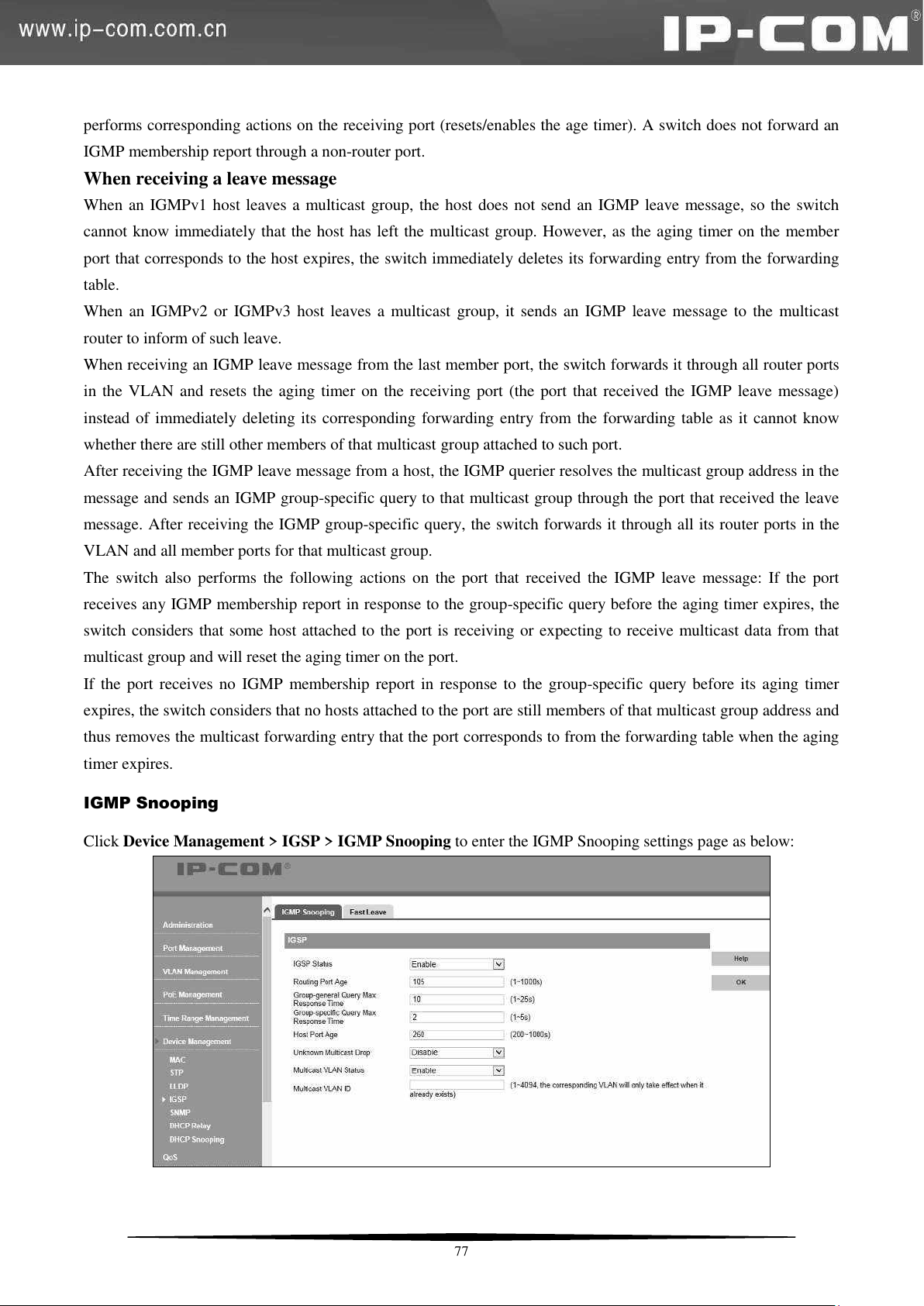
performs corresponding actions on the receiving port (resets/enables the age timer). A switch does not forward an
IGMP membership report through a non-router port.
When receiving a leave message
When an IGMPv1 host leaves a multicast group, the host does not send an IGMP leave message, so the switch
cannot know immediately that the host has left the multicast group. However, as the aging timer on the member
port that corresponds to the host expires, the switch immediately deletes its forwarding entry from the forwarding
table.
When an IGMPv2 or IGMPv3 host leaves a multicast group, it sends an IGMP leave message to the multicast
router to inform of such leave.
When receiving an IGMP leave message from the last member port, the switch forwards it through all router ports
in the VLAN and resets the aging timer on the receiving port (the port that received the IGMP leave message)
instead of immediately deleting its corresponding forwarding entry from the forwarding table as it cannot know
whether there are still other members of that multicast
group attached to such port.
After receiving the IGMP leave message from a host, the IGMP querier resolves the multicast group address in the
message and sends an IGMP group-specific query to that multicast group through the port that received the leave
message. After receiving the IGMP group-specific query, the switch forwards it through all its router ports in the
VLAN and all member ports for that multicast group.
The switch also performs the following actions on the port that received the IGMP leave message: If the port
receives any IGMP membership report in response to the group-specific query before the aging timer expires, the
switch considers that some host attached to the port is receiving or expecting to receive multicast data from that
multicast group and will reset the aging timer on the port.
If the port receives no IGMP membership report in response to the group-specific query before its aging timer
expires, the switch considers that no hosts attached to the port are still members of that multicast group address and
thus removes the multicast forwarding entry that the port corresponds to from the forwarding table when the aging
timer expires.
IGMP Snooping
Click Device Management > IGSP > IGMP Snooping to enter the IGMP Snooping settings page as below:
77
Page 85
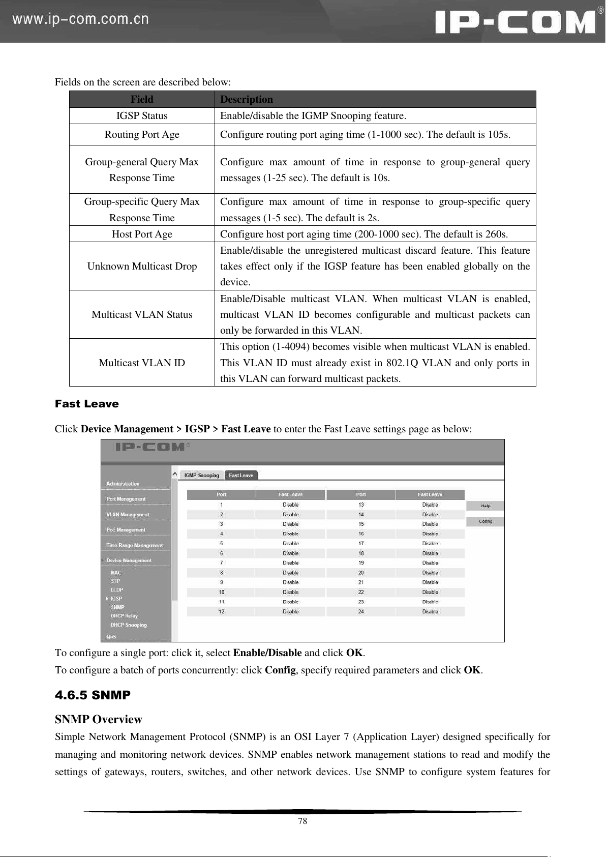
Fields on the screen are described below:
Field
Description
IGSP Status
Enable/disable the IGMP Snooping feature.
Routing Port Age
Configure routing port aging time (1-1000 sec). The default is 105s.
Group-general Query Max
Response Time
Configure max amount of time in response to group-general query
messages (1-25 sec). The default is 10s.
Group-specific Query Max
Response Time
Configure max amount of time in response to group-specific query
messages (1-5 sec). The default is 2s.
Host Port Age
Configure host port aging time (200-1000 sec). The default is 260s.
Unknown Multicast Drop
Enable/disable the unregistered multicast discard feature. This feature
takes effect only if the IGSP feature has been enabled globally on the
device.
Multicast VLAN Status
Enable/Disable multicast VLAN. When multicast VLAN is enabled,
multicast VLAN ID becomes configurable and multicast packets can
only be forwarded in this VLAN.
Multicast VLAN ID
This option (1-4094) becomes visible when multicast VLAN is enabled.
This VLAN ID must already exist in 802.1Q VLAN and only ports in
this VLAN can forward multicast packets.
Fast Leave
Click Device Management > IGSP > Fast Leave to enter the Fast Leave settings page as below:
To configure a single port: click it, select Enable/Disable and click OK.
To configure a batch of ports concurrently: click Config, specify required parameters and click OK.
4.6.5 SNMP
SNMP Overview
Simple Network Management Protocol (SNMP) is an OSI Layer 7 (Application Layer) designed specifically for
managing and monitoring network devices. SNMP enables network management stations to read and modify the
settings of gateways, routers, switches, and other network devices. Use SNMP to configure system features for
78
Page 86
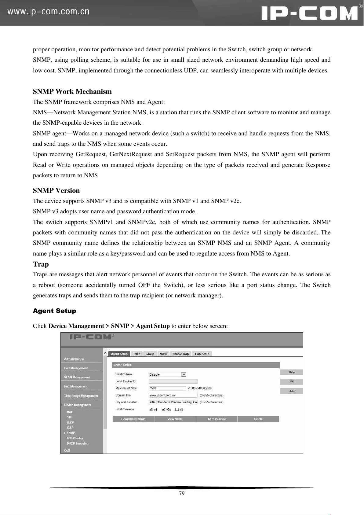
proper operation, monitor performance and detect potential problems in the Switch, switch group or network.
SNMP, using polling scheme, is suitable for use in small sized network environment demanding high speed and
low cost. SNMP, implemented through the connectionless UDP, can seamlessly interoperate with multiple devices.
SNMP Work Mechanism
The SNMP framework comprises NMS and Agent:
NMS—Network Management Station NMS, is a station that runs the SNMP client software to monitor and manage
the SNMP-capable devices in the network.
SNMP agent—Works on a managed network device (such a switch) to receive and handle requests from the NMS,
and send traps to the NMS when some events occur.
Upon receiving GetRequest, GetNextRequest and SetRequest packets from NMS, the SNMP agent will perform
Read or Write operations on managed objects depending on the type of packets received and generate Response
packets to return to NMS
SNMP Version
The device supports SNMP v3 and is compatible with SNMP v1 and SNMP v2c.
SNMP v3 adopts user name and password authentication mode.
The switch supports SNMPv1 and SNMPv2c, both of which use community names for authentication. SNMP
packets with community names that did not pass the authentication on the device will simply be discarded. The
SNMP community name defines the relationship between an SNMP NMS and an SNMP Agent. A community
name plays a similar role as a key/password and can be used to regulate access from NMS to Agent.
Trap
Traps are messages that alert network personnel of events that occur on the Switch. The events can be as serious as
a reboot (someone accidentally turned OFF the Switch), or less serious like a port status change. The Switch
generates traps and sends them to the trap recipient (or network manager).
Agent Setup
Click Device Management > SNMP > Agent Setup to enter below screen:
79
Page 87

To enable SNMP
Select Enable from the SNMP Status drop-down list.
You will see the Local Engine ID after enabling SNMP. This field is not configurable.
Specify a Max Packet Size value, the default is 1500.
Configure contact info. The default is www.ip-com.com.
Here you can specify device's physical location.
SNMP Version: Select V1, V2c or V3.
Click Add to create a community name as seen below:
Note: You must create a view before you can create a community.
Community Name: Click Standard and select public or private; click Custom and enter a community name of up
to 31 characters.
Access Right: Select Read only or Read & Write.
Click OK.
Now you can use the V1, or V2c community name to view or configure settings of nodes in the MIB.
User
Click Device Management > SNMP > User to enter the screen below:
80
Page 88
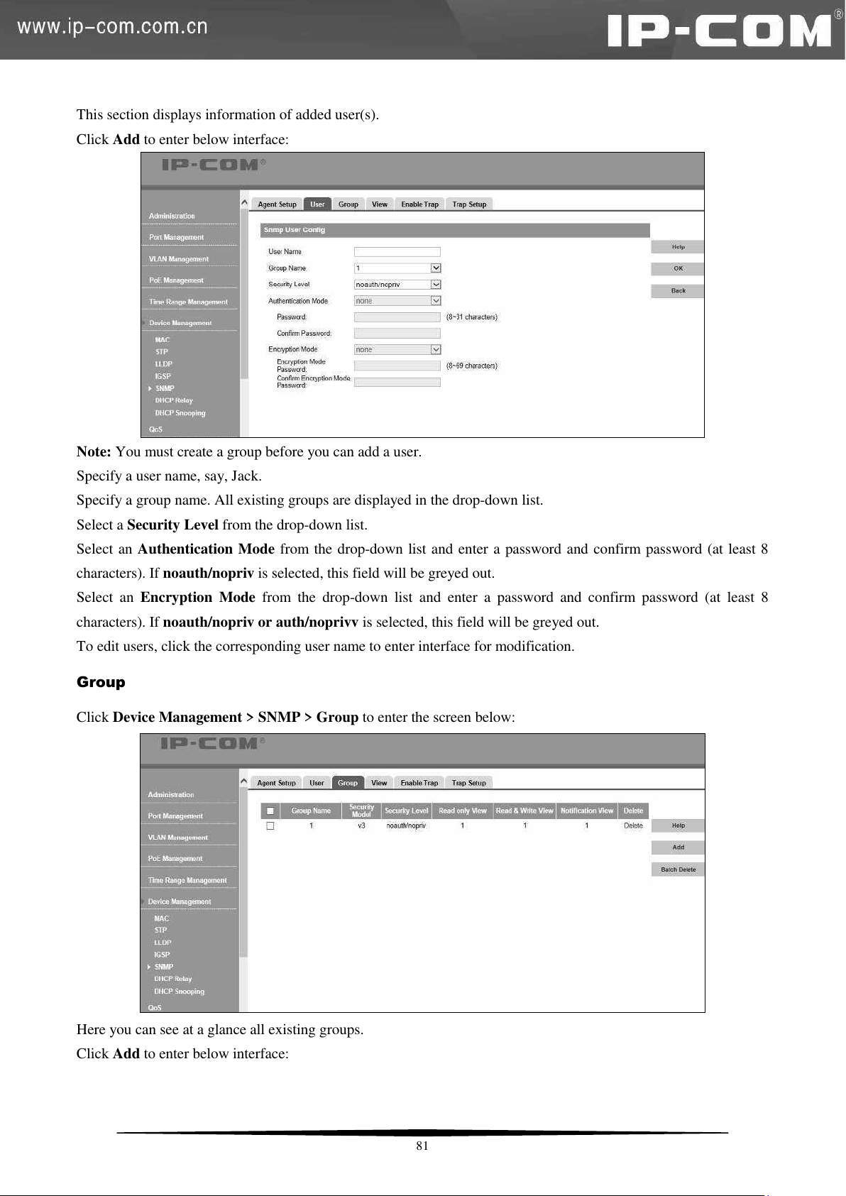
This section displays information of added user(s).
Click Add to enter below interface:
Note: You must create a group before you can add a user.
Specify a user name, say, Jack.
Specify a group name. All existing groups are displayed in the drop-down list.
Select a Security Level from the drop-down list.
Select an Authentication Mode from the drop-down list and enter a password and confirm password (at least 8
characters). If noauth/nopriv is selected, this field will be greyed out.
Select an Encryption Mode from the drop-down list and enter a password and confirm password (at least 8
characters). If noauth/nopriv or auth/noprivv is selected, this field will be greyed out.
To edit users, click the corresponding user name to enter interface for modification.
Group
Click Device Management > SNMP > Group to enter the screen below:
Here you can see at a glance all existing groups.
Click Add to enter below interface:
81
Page 89
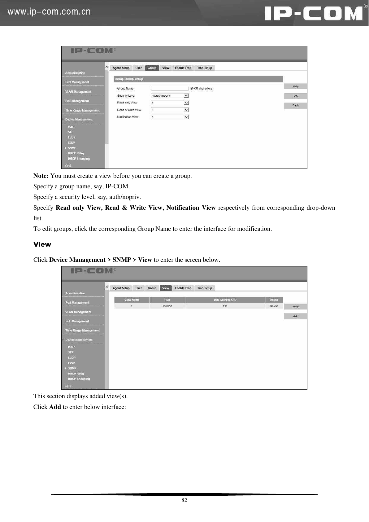
Note: You must create a view before you can create a group.
Specify a group name, say, IP-COM.
Specify a security level, say, auth/nopriv.
Specify Read only View, Read & Write View, Notification View respectively from corresponding drop-down
list.
To edit groups, click the corresponding Group Name to enter the interface for modification.
View
Click Device Management > SNMP > View to enter the screen below.
This section displays added view(s).
Click Add to enter below interface:
82
Page 90
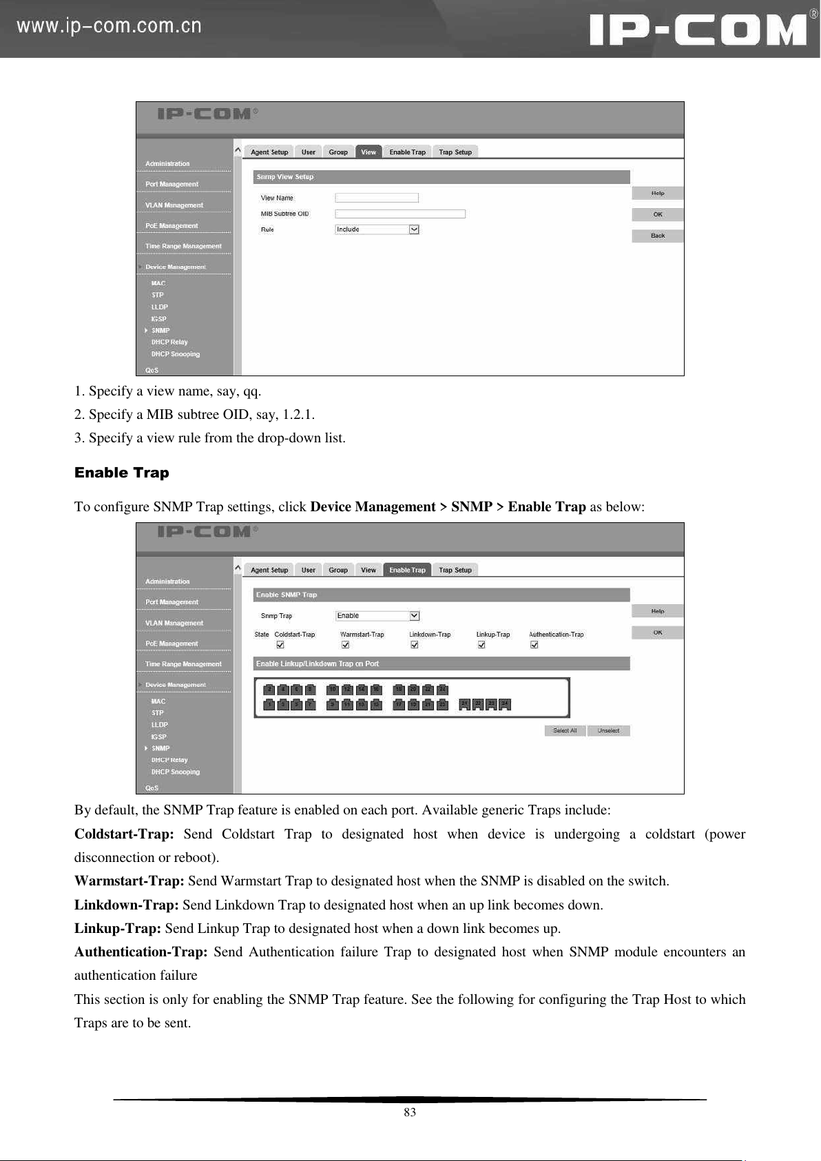
1. Specify a view name, say, qq.
2. Specify a MIB subtree OID, say, 1.2.1.
3. Specify a view rule from the drop-down list.
Enable Trap
To configure SNMP Trap settings, click Device Management > SNMP > Enable Trap as below:
By default, the SNMP Trap feature is enabled on each port. Available generic Traps include:
Coldstart-Trap: Send Coldstart Trap to designated host when device is undergoing a coldstart (power
disconnection or reboot).
Warmstart-Trap: Send Warmstart Trap to designated host when the SNMP is disabled on the switch.
Linkdown-Trap: Send Linkdown Trap to designated host when an up link becomes down.
Linkup-Trap: Send Linkup Trap to designated host when a down link becomes up.
Authentication-Trap: Send Authentication failure Trap to designated host when SNMP module encounters an
authentication failure
This section is only for enabling the SNMP Trap feature. See the following for configuring the Trap Host to which
Traps are to be sent.
83
Page 91
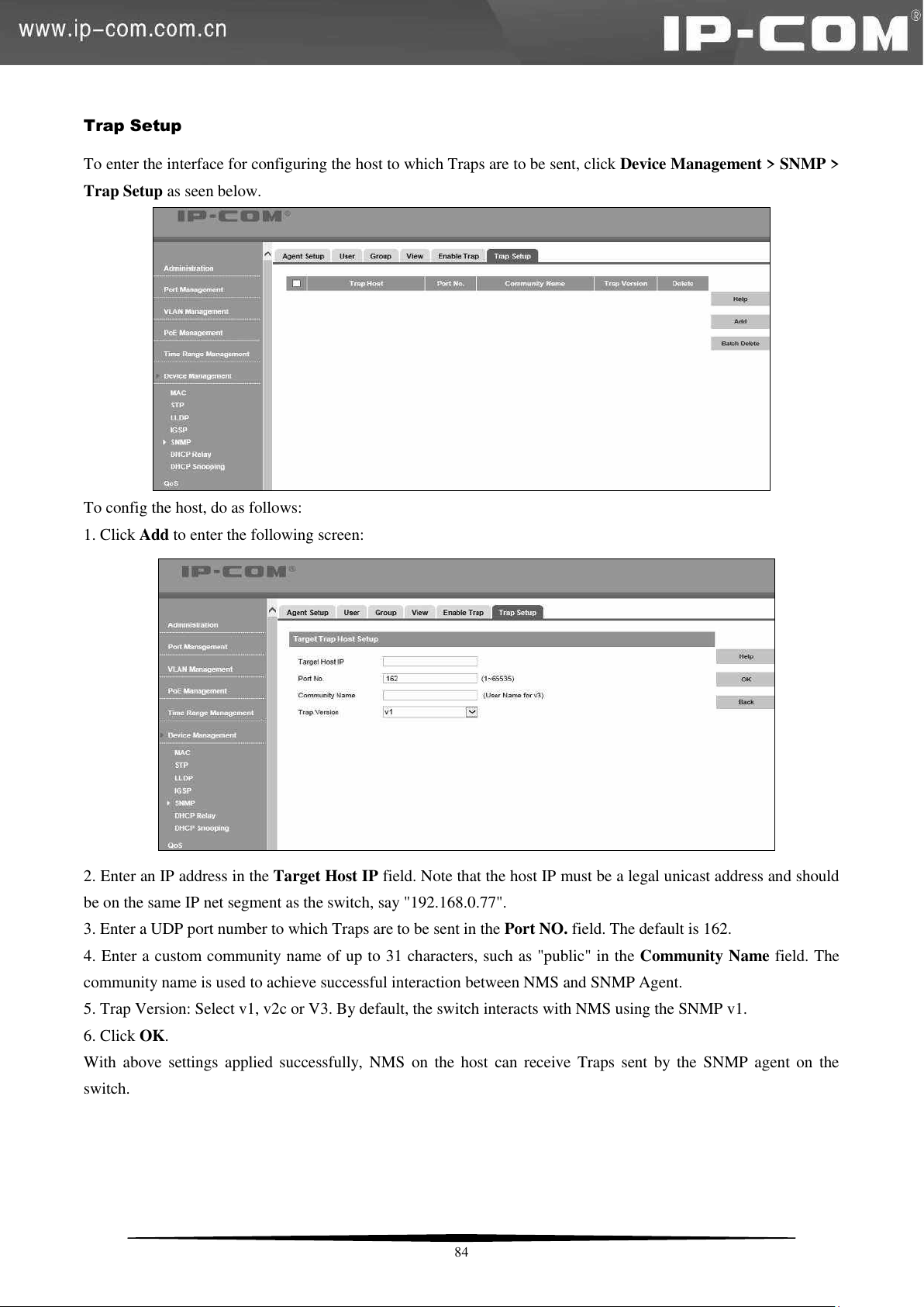
Trap Setup
To enter the interface for configuring the host to which Traps are to be sent, click Device Management > SNMP >
Trap Setup as seen below.
To config the host, do as follows:
1. Click Add to enter the following screen:
2. Enter an IP address in the Target Host IP field. Note that the host IP must be a legal unicast address and should
be on the same IP net segment as the switch, say "192.168.0.77".
3. Enter a UDP port number to which Traps are to be sent in the Port NO. field. The default is 162.
4. Enter a custom community name of up to 31 characters, such as "public" in the Community Name field. The
community name is used to achieve successful interaction between NMS and SNMP Agent.
5. Trap Version: Select v1, v2c or V3. By default, the switch interacts with NMS using the SNMP v1.
6. Click OK.
With above settings applied successfully, NMS on the host can receive Traps sent by the SNMP agent on the
switch.
84
Page 92
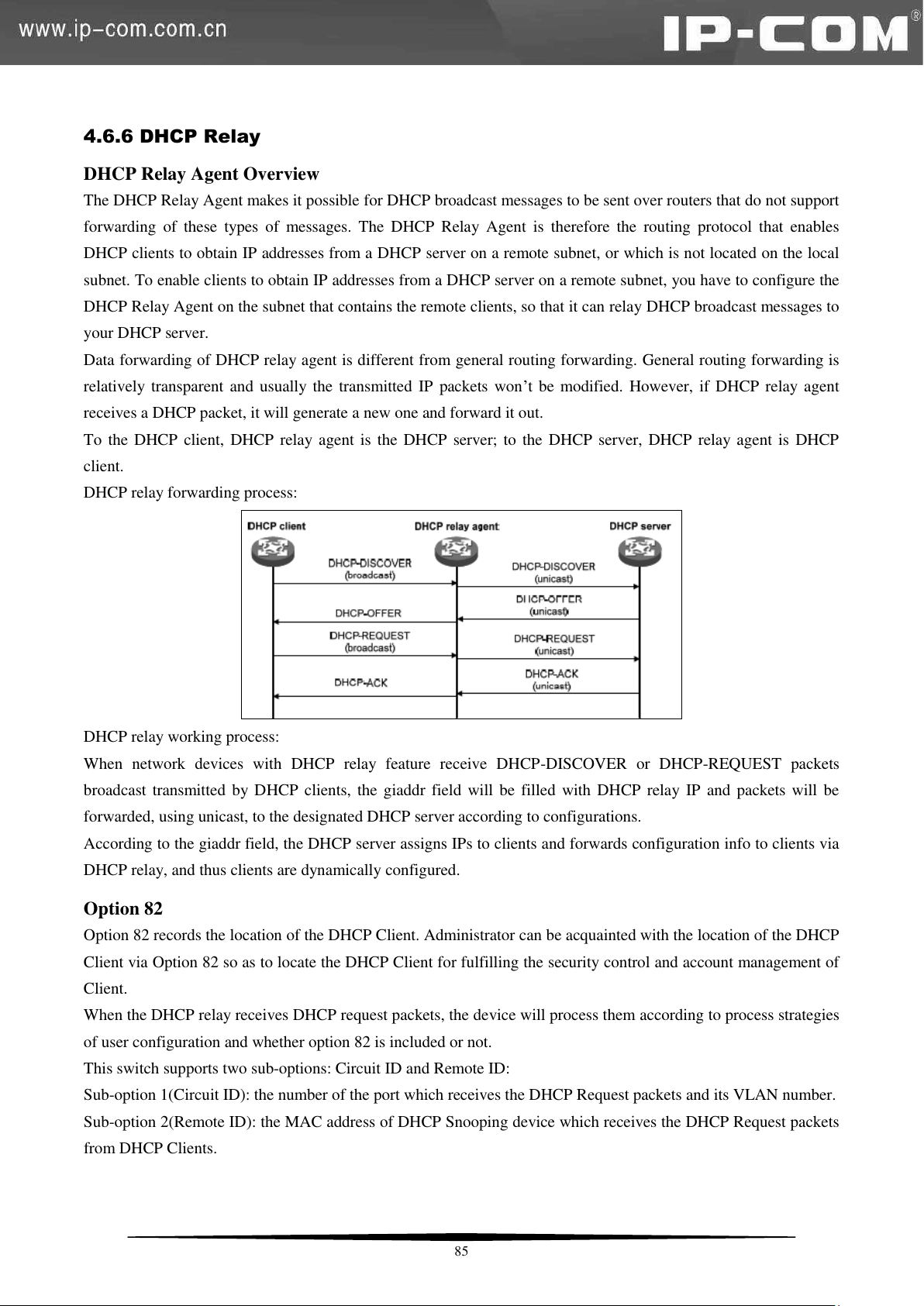
4.6.6 DHCP Relay
DHCP Relay Agent Overview
The DHCP Relay Agent makes it possible for DHCP broadcast messages to be sent over routers that do not support
forwarding of these types of messages. The DHCP Relay Agent is therefore the routing protocol that enables
DHCP clients to obtain IP addresses from a DHCP server on a remote subnet, or which is not located on the local
subnet. To enable clients to obtain IP addresses from a DHCP server on a remote subnet, you have to configure the
DHCP Relay Agent on the subnet that contains the remote clients, so that it can relay DHCP broadcast messages to
your DHCP server.
Data forwarding of DHCP relay agent is different from general routing forwarding. General routing forwarding is
relatively transparent and usually the transmitted IP packets won’t be modified. However, if DHCP relay agent
receives a DHCP packet, it will generate a new one and forward it out.
To the DHCP client, DHCP relay agent is the DHCP server; to the DHCP server, DHCP relay agent is DHCP
client.
DHCP relay forwarding process:
DHCP relay working process:
When network devices with DHCP relay feature receive DHCP-DISCOVER or DHCP-REQUEST packets
broadcast transmitted by DHCP clients, the giaddr field will be filled with DHCP relay IP and packets will be
forwarded, using unicast, to the designated DHCP server according to configurations.
According to the giaddr field, the DHCP server assigns IPs to clients and forwards configuration info to clients via
DHCP relay, and thus clients are dynamically configured.
Option 82
Option 82 records the location of the DHCP Client. Administrator can be acquainted with the location of the DHCP
Client via Option 82 so as to locate the DHCP Client for fulfilling the security control and account management of
Client.
When the DHCP relay receives DHCP request packets, the device will process them according to process strategies
of user configuration and whether option 82 is included or not.
This switch supports two sub-options: Circuit ID and Remote ID:
Sub-option 1(Circuit ID): the number of the port which receives the DHCP Request packets and its VLAN number.
Sub-option 2(Remote ID): the MAC address of DHCP Snooping device which receives the DHCP Request packets
from DHCP Clients.
85
Page 93
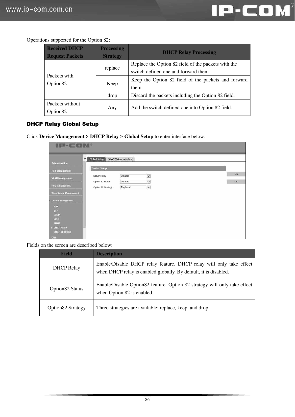
Received DHCP
Request Packets
Processing
Strategy
DHCP Relay Processing
Packets with
Option82
replace
Replace the Option 82 field of the packets with the
switch defined one and forward them.
Keep
Keep the Option 82 field of the packets and forward
them.
drop
Discard the packets including the Option 82 field.
Packets without
Option82
Any
Add the switch defined one into Option 82 field.
Field
Description
DHCP Relay
Enable/Disable DHCP relay feature. DHCP relay will only take effect
when DHCP relay is enabled globally. By default, it is disabled.
Option82 Status
Enable/Disable Option82 feature. Option 82 strategy will only take effect
when Option 82 is enabled.
Option82 Strategy
Three strategies are available: replace, keep, and drop.
Operations supported for the Option 82:
DHCP Relay Global Setup
Click Device Management > DHCP Relay > Global Setup to enter interface below:
Fields on the screen are described below:
86
Page 94
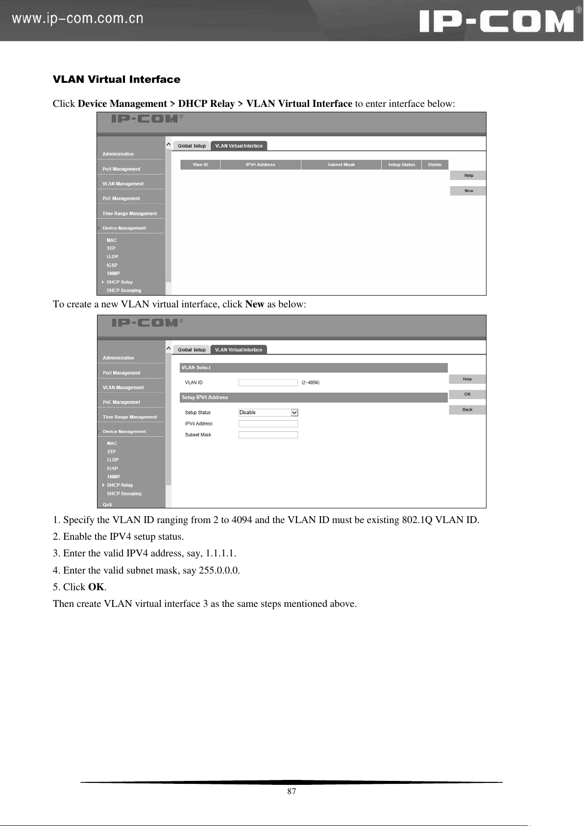
VLAN Virtual Interface
Click Device Management > DHCP Relay > VLAN Virtual Interface to enter interface below:
To create a new VLAN virtual interface, click New as below:
1. Specify the VLAN ID ranging from 2 to 4094 and the VLAN ID must be existing 802.1Q VLAN ID.
2. Enable the IPV4 setup status.
3. Enter the valid IPV4 address, say, 1.1.1.1.
4. Enter the valid subnet mask, say 255.0.0.0.
5. Click OK.
Then create VLAN virtual interface 3 as the same steps mentioned above.
87
Page 95
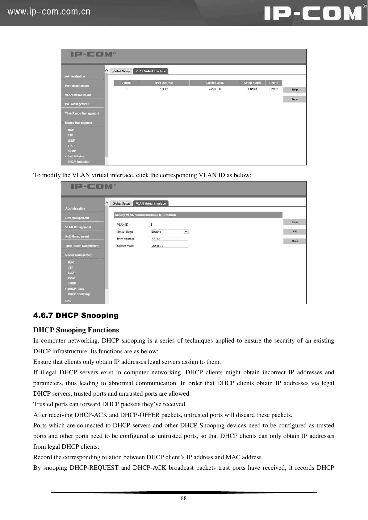
To modify the VLAN virtual interface, click the corresponding VLAN ID as below:
4.6.7 DHCP Snooping
DHCP Snooping Functions
In computer networking, DHCP snooping is a series of techniques applied to ensure the security of an existing
DHCP infrastructure. Its functions are as below:
Ensure that clients only obtain IP addresses legal servers assign to them.
If illegal DHCP servers exist in computer networking, DHCP clients might obtain incorrect IP addresses and
parameters, thus leading to abnormal communication. In order that DHCP clients obtain IP addresses via legal
DHCP servers, trusted ports and untrusted ports are allowed:
Trusted ports can forward DHCP packets they’ve received.
After receiving DHCP-ACK and DHCP-OFFER packets, untrusted ports will discard these packets.
Ports which are connected to DHCP servers and other DHCP Snooping devices need to be configured as trusted
ports and other ports need to be configured as untrusted ports, so that DHCP clients can only obtain IP addresses
from legal DHCP clients.
Record the corresponding relation between DHCP client’s IP address and MAC address.
By snooping DHCP-REQUEST and DHCP-ACK broadcast packets trust ports have received, it records DHCP
88
Page 96
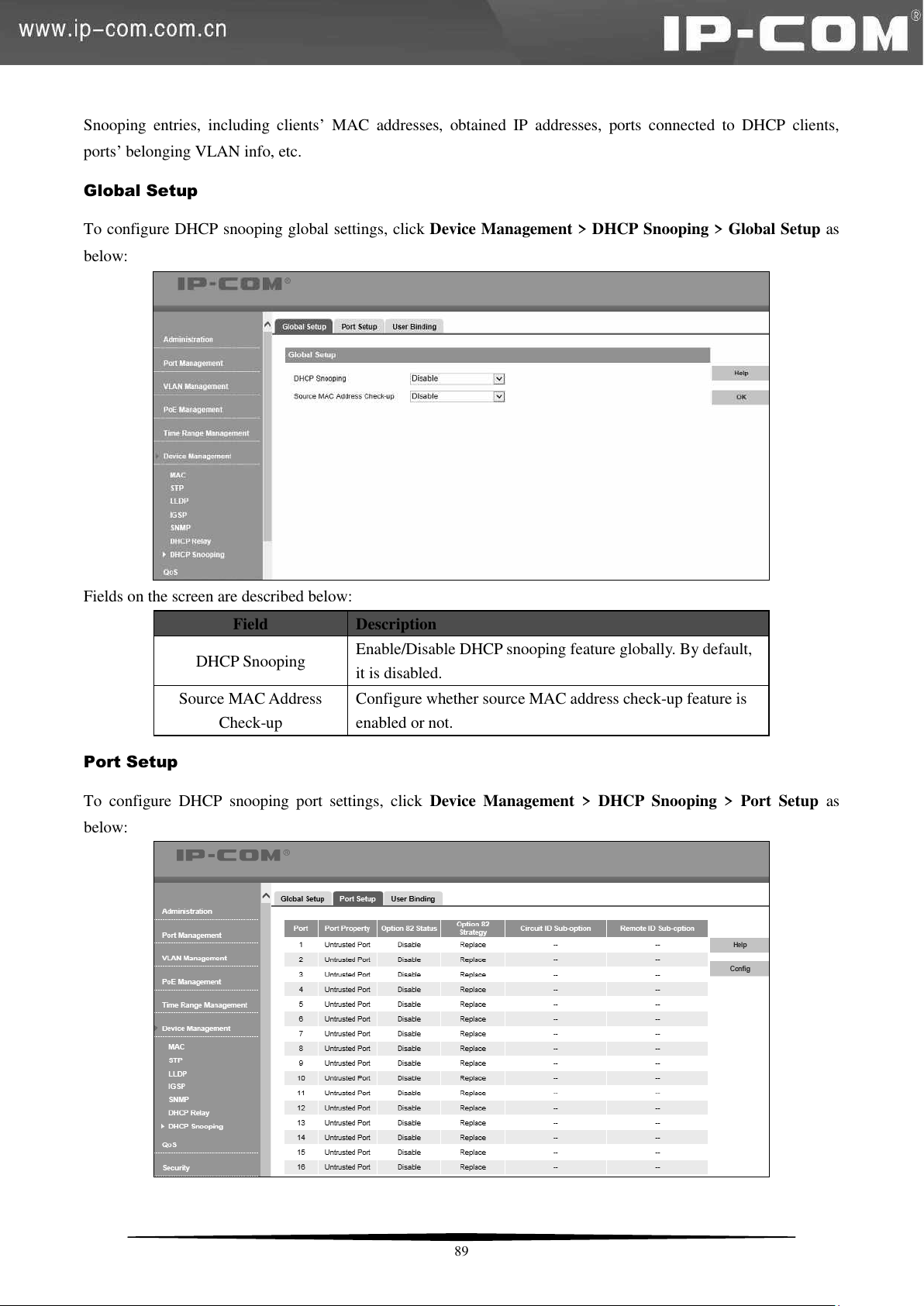
Field
Description
DHCP Snooping
Enable/Disable DHCP snooping feature globally. By default,
it is disabled.
Source MAC Address
Check-up
Configure whether source MAC address check-up feature is
enabled or not.
Snooping entries, including clients’ MAC addresses, obtained IP addresses, ports connected to DHCP clients,
ports’ belonging VLAN info, etc.
Global Setup
To configure DHCP snooping global settings, click Device Management > DHCP Snooping > Global Setup as
below:
Fields on the screen are described below:
Port Setup
To configure DHCP snooping port settings, click Device Management > DHCP Snooping > Port Setup as
below:
89
Page 97
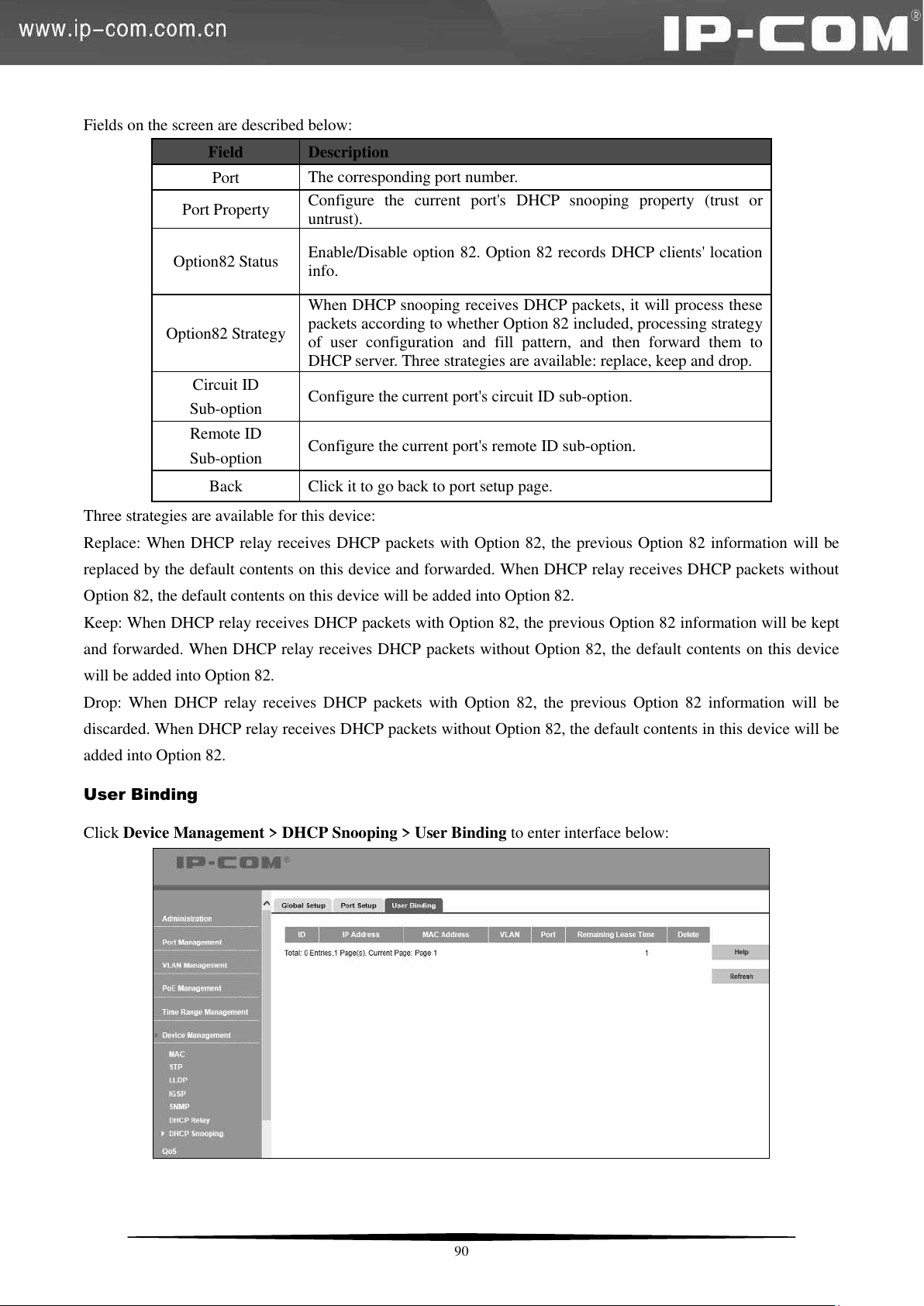
Fields on the screen are described below:
Field
Description
Port
The corresponding port number.
Port Property
Configure the current port's DHCP snooping property (trust or
untrust).
Option82 Status
Enable/Disable option 82. Option 82 records DHCP clients' location
info.
Option82 Strategy
When DHCP snooping receives DHCP packets, it will process these
packets according to whether Option 82 included, processing strategy
of user configuration and fill pattern, and then forward them to
DHCP server. Three strategies are available: replace, keep and drop.
Circuit ID
Sub-option
Configure the current port's circuit ID sub-option.
Remote ID
Sub-option
Configure the current port's remote ID sub-option.
Back
Click it to go back to port setup page.
Three strategies are available for this device:
Replace: When DHCP relay receives DHCP packets with Option 82, the previous Option 82 information will be
replaced by the default contents on this device and forwarded. When DHCP relay receives DHCP packets without
Option 82, the default contents on this device will be added into Option 82.
Keep: When DHCP relay receives DHCP packets with Option 82, the previous Option 82 information will be kept
and forwarded. When DHCP relay receives DHCP packets without Option 82, the default contents on this device
will be added into Option 82.
Drop: When DHCP relay receives DHCP packets with Option 82, the previous Option 82 information will be
discarded. When DHCP relay receives DHCP packets without Option 82, the default contents in this device will be
added into Option 82.
User Binding
Click Device Management > DHCP Snooping > User Binding to enter interface below:
90
Page 98
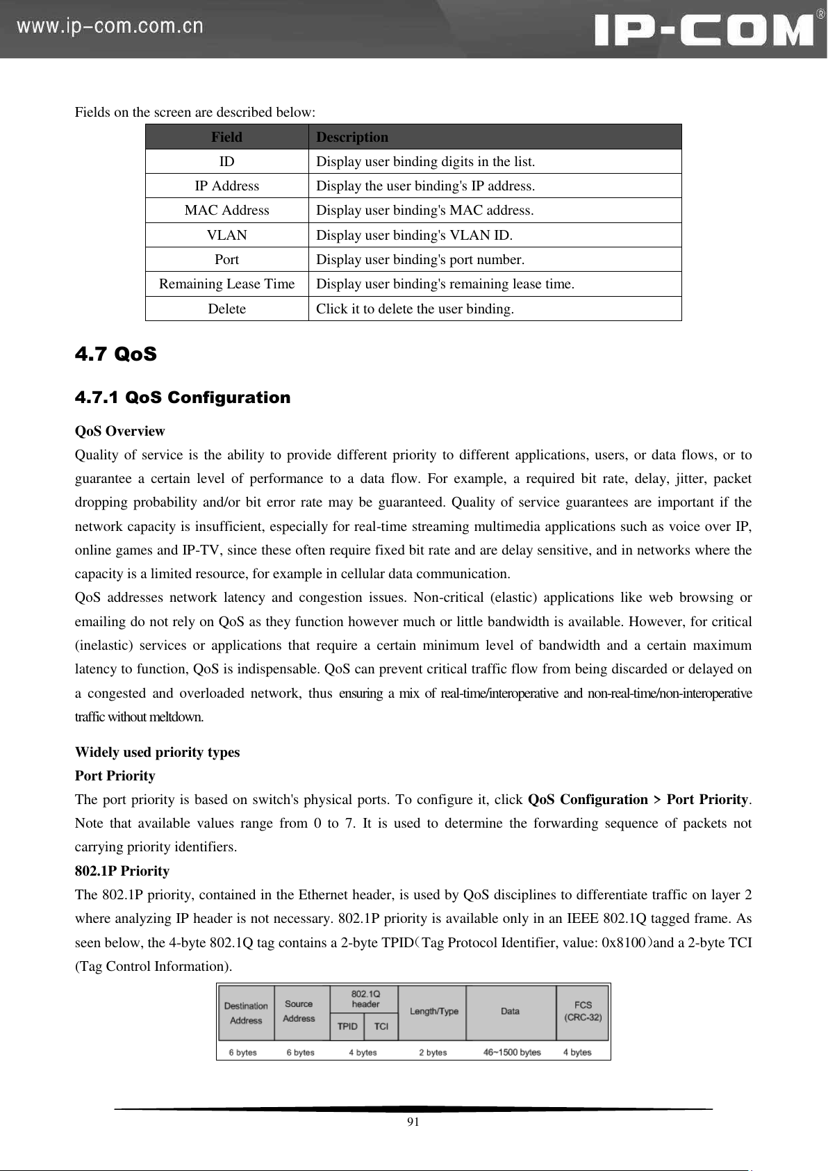
Field
Description
ID
Display user binding digits in the list.
IP Address
Display the user binding's IP address.
MAC Address
Display user binding's MAC address.
VLAN
Display user binding's VLAN ID.
Port
Display user binding's port number.
Remaining Lease Time
Display user binding's remaining lease time.
Delete
Click it to delete the user binding.
Fields on the screen are described below:
4.7 QoS
4.7.1 QoS Configuration
QoS Overview
Quality of service is the ability to provide different priority to different applications, users, or data flows, or to
guarantee a certain level of performance to a data flow. For example, a required bit rate, delay, jitter, packet
dropping probability and/or bit error rate may be guaranteed. Quality of service guarantees are important if the
network capacity is insufficient, especially for real-time streaming multimedia applications such as voice over IP,
online games and IP-TV, since these often require fixed bit rate and are delay sensitive, and in networks where the
capacity is a limited resource, for example in cellular data communication.
QoS addresses network latency and congestion issues. Non-critical (elastic) applications like web browsing or
emailing do not rely on QoS as they function however much or little bandwidth is available. However, for critical
(inelastic) services or applications that require a certain minimum level of bandwidth and a certain maximum
latency to function, QoS is indispensable. QoS can prevent critical traffic flow from being discarded or delayed on
a congested and overloaded network, thus ensuring a mix of real-time/interoperative and non-real-time/non-interoperative
traffic without meltdown.
Widely used priority types
Port Priority
The port priority is based on switch's physical ports. To configure it, click QoS Configuration > Port Priority.
Note that available values range from 0 to 7. It is used to determine the forwarding sequence of packets not
carrying priority identifiers.
802.1P Priority
The 802.1P priority, contained in the Ethernet header, is used by QoS disciplines to differentiate traffic on layer 2
where analyzing IP header is not necessary. 802.1P priority is available only in an IEEE 802.1Q tagged frame. As
seen below, the 4-byte 802.1Q tag contains a 2-byte TPID(Tag Protocol Identifier, value: 0x8100)and a 2-byte TCI
(Tag Control Information).
91
Page 99
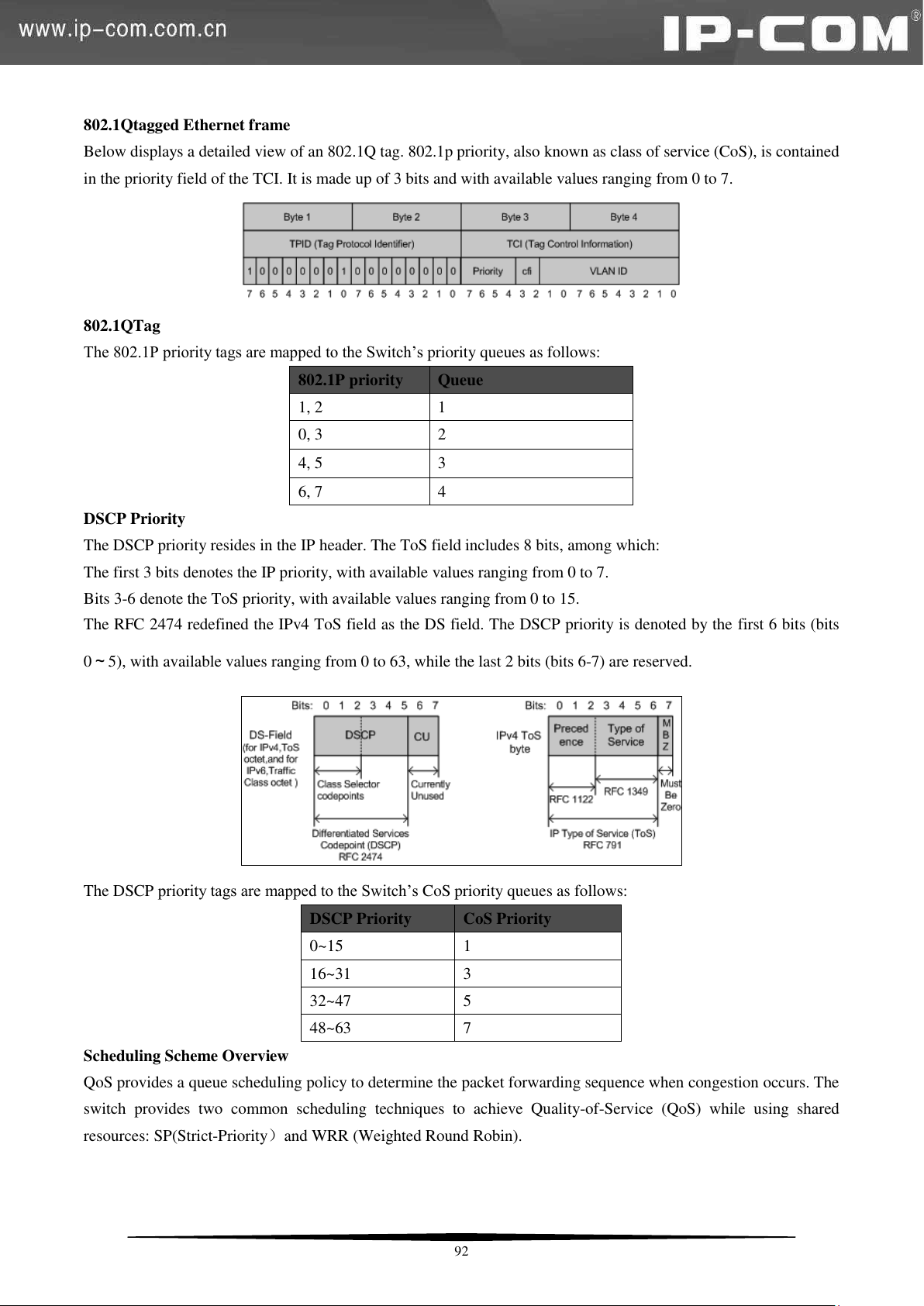
802.1P priority
Queue
1, 2
1
0, 3
2
4, 5
3
6, 7
4
DSCP Priority
CoS Priority
0~15
1
16~31
3
32~47
5
48~63
7
802.1Qtagged Ethernet frame
Below displays a detailed view of an 802.1Q tag. 802.1p priority, also known as class of service (CoS), is contained
in the priority field of the TCI. It is made up of 3 bits and with available values ranging from 0 to 7.
802.1QTag
The 802.1P priority tags are mapped to the Switch’s priority queues as follows:
DSCP Priority
The DSCP priority resides in the IP header. The ToS field includes 8 bits, among which:
The first 3 bits denotes the IP priority, with available values ranging from 0 to 7.
Bits 3-6 denote the ToS priority, with available values ranging from 0 to 15.
The RFC 2474 redefined the IPv4 ToS field as the DS field. The DSCP priority is denoted by the first 6 bits (bits
0~5), with available values ranging from 0 to 63, while the last 2 bits (bits 6-7) are reserved.
The DSCP priority tags are mapped to the Switch’s CoS priority queues as follows:
Scheduling Scheme Overview
QoS provides a queue scheduling policy to determine the packet forwarding sequence when congestion occurs. The
switch provides two common scheduling techniques to achieve Quality-of-Service (QoS) while using shared
resources: SP(Strict-Priority)and WRR (Weighted Round Robin).
92
Page 100
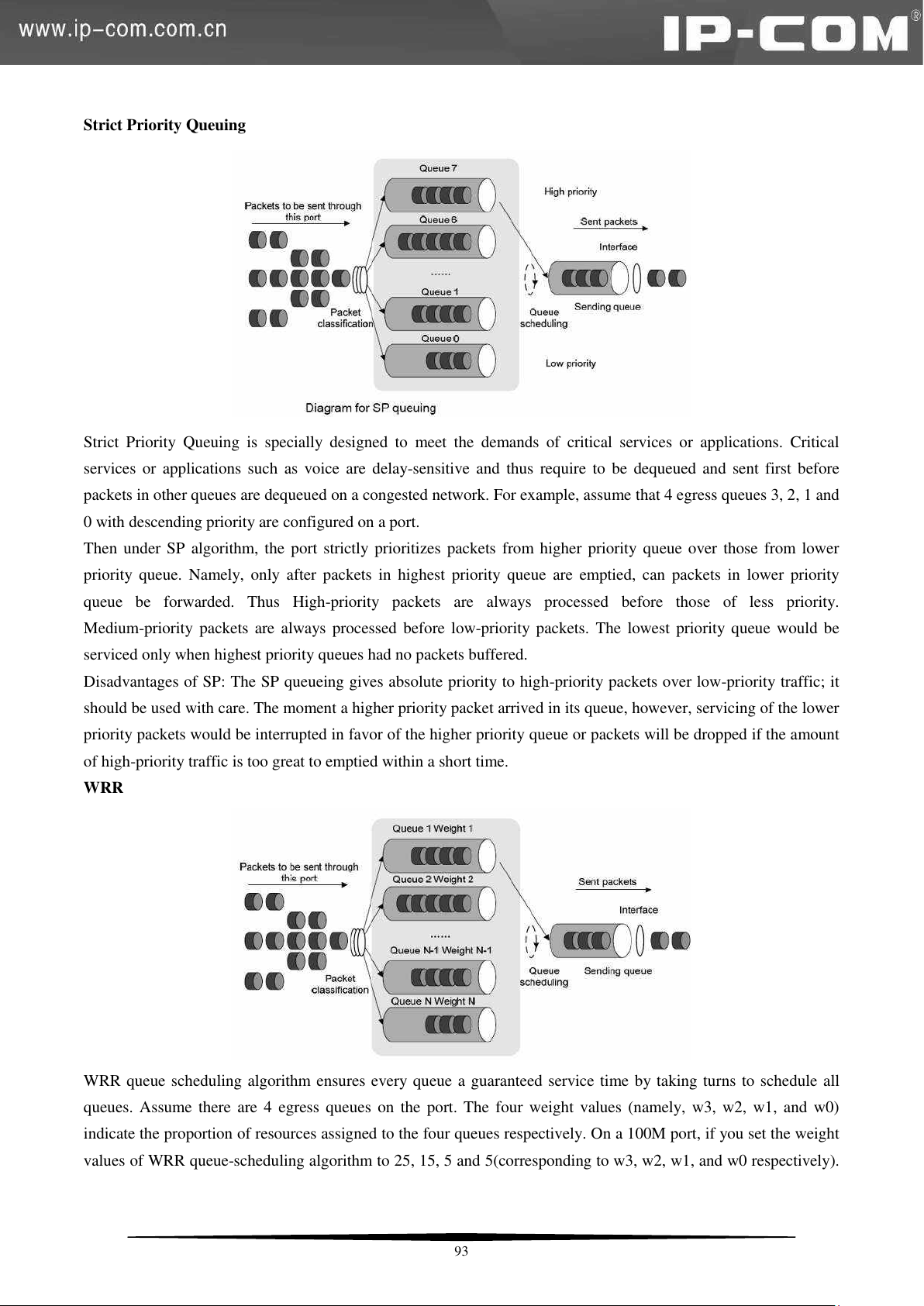
Strict Priority Queuing
Strict Priority Queuing is specially designed to meet the demands of critical services or applications. Critical
services or applications such as voice are delay-sensitive and thus require to be dequeued and sent first before
packets in other queues are dequeued on a congested network. For example, assume that 4 egress queues 3, 2, 1 and
0 with descending priority are configured on a port.
Then under SP algorithm, the port strictly prioritizes packets from higher priority queue over those from lower
priority queue. Namely, only after packets in highest priority queue are emptied, can packets in lower priority
queue be forwarded. Thus High-priority packets are always processed before those of less priority.
Medium-priority packets are always processed before low-priority packets. The lowest priority queue would be
serviced only when highest priority queues had no packets buffered.
Disadvantages of SP: The SP queueing gives absolute priority to high-priority packets over low-priority traffic; it
should be used with care. The moment a higher priority packet arrived in its queue, however, servicing of the lower
priority packets would be interrupted in favor of the higher priority queue or packets will be dropped if the amount
of high-priority traffic is too great to emptied within a short time.
WRR
WRR queue scheduling algorithm ensures every queue a guaranteed service time by taking turns to schedule all
queues. Assume there are 4 egress queues on the port. The four weight values (namely, w3, w2, w1, and w0)
indicate the proportion of resources assigned to the four queues respectively. On a 100M port, if you set the weight
values of WRR queue-scheduling algorithm to 25, 15, 5 and 5(corresponding to w3, w2, w1, and w0 respectively).
93
 Loading...