

Page 1
1250 - 1280
MANUALE ISTRUZIONI PER L’USO /
OPERATOR’S MANUAL / MANUEL D’INSTRUCTIONS /
BEDIENUNGSANLEITUNG /
MANUAL DE INSTRUCCIONES / BRUKERHÅNDBOK /
GEBRUIKERSHANDLEIDING / MANUAL DE UTILIZAÇÃO /
INSTRUKTIONSBOK / МАШИНА ДЛЯ МОЙКИ И СУШКИ ПОЛОВ
/ KULLANIM KILAVUZU
Consultare attentamente questo manuale prima di procedere a qualsiasi intervento sulla macchina
Read this manual carefully before carrying out any work on the machine
Lire attentivement ce manuel avant toute intervention sur la machine
Vorliegendes Handbuch vor jedem Eingri an der Maschine aufmerksam durchlesen
Consulte detenidamente este manual antes de llevar a cabo cualquier trabajo en la máquina
Konsulter denne håndboken nøye før du går i gang med noen som helst type inngrep på maskinen
Raadpleeg deze handleiding aandachtig alvorens met enige werkzaamheid aan de machine te beginnen
Consulte atentamente este manual antes de efectuar qualquer intervenção na máquina
Läs noggrant igenom denna handbok innan du utför något som helst ingrepp på maskinen
Внимательно ознакомьтесь с данной инструкцией до проведения любой работы с машиной
Makine ile herhangi bir işlem yapmadan önce bu kılavuzu dikkatle okuyun
Page 2

ENGLISH
(Translated instructions)
ITGB
2
Page 3

TECHNICAL CHARACTERISTICS ........................................................................4
MACHINE DIMENSIONS ........................................................................................7
SAFETY SYMBOLS ................................................................................................8
GENERAL INFORMATION ..................................................................................... 9
Purpose of this manual .................................................................................................................. 9
Identifying the machine .................................................................................................................. 9
Documentation provided with the machine ................................................................................... 10
TECHNICAL INFORMATION .................................................................................11
General description ....................................................................................................................... 11
Parts of the machine ..................................................................................................................... 11
Hazard areas................................................................................................................................. 12
Accessories ................................................................................................................................... 12
SAFETY INFORMATION .......................................................................................13
Safety precautions ........................................................................................................................ 13
MOVEMENT INSTALLATION ...............................................................................15
Lifting and transporting the packaged machine ............................................................................ 15
Delivery checks ............................................................................................................................. 15
Unpacking ..................................................................................................................................... 15
Batteries (Battery version)............................................................................................................. 15
Batteries: preparation .................................................................................................................... 16
Batteries: installation and connection............................................................................................ 16
Batteries: removal ......................................................................................................................... 17
Choosing a battery charger ........................................................................................................... 17
Preparing the battery charger ...................................................................................................... 17
Preparing the engine (Petrol and Dual Power versions) .............................................................. 17
Preparing the hydraulic circuit (Petrol and Diesel versions).......................................................... 17
Fitting the side brushes ................................................................................................................. 17
Lifting and transporting the machine ............................................................................................. 18
PRACTICAL GUIDE FOR THE OPERATOR ......................................................... 19
Preparing the machine for work .................................................................................................... 19
Controls of the Battery and Dual Power versions ......................................................................... 20
Operating the Battery and Dual Power versions ........................................................................... 22
Controls of the Petrol and Diesel versions .................................................................................... 22
Operating the Petrol and Diesel versions...................................................................................... 25
Emptying the bottom unloading debris bin .................................................................................... 26
Emptying the top unloading debris bin .......................................................................................... 27
Finishing work ............................................................................................................................... 27
Moving the machine when not in operation................................................................................... 27
PERIODS OF INACTIVITY ....................................................................................28
MAINTENANCE INSTRUCTIONS .........................................................................29
Maintenance - General rules ......................................................................................................... 29
Replacing/installing the main brush ............................................................................................. 29
Adjusting the main brush............................................................................................................... 30
Replacing/installing the side brushes ............................................................................................ 30
Adjusting the side brushes ............................................................................................................ 31
Replacing/installing the suction lter ............................................................................................. 31
Fuses: replacing ............................................................................................................................ 33
Battery maintenance and charging ............................................................................................... 34
Changing the engine oil ................................................................................................................ 34
Top up hydraulic circuit oil on PETROL and DIESEL version .......................................................35
Periodic checks ............................................................................................................................. 36
TROUBLESHOOTING ...........................................................................................37
DISPLAY ALARMS ................................................................................................ 39
TECHNICAL MENU ............................................................................................... 41
Page 4

TECHNICAL CHARACTERISTICS
BATTERY DUAL POWER PETROL DIESEL
Cleaning width mm 1100
2
Cleaning capacity per hour m
Main brush motor power W 600 - -
Side brush motor power W 90 - -
Drive motor power 450 W 98 Cm
Internal combustion engine starting W -
Internal combustion engine power W - 4100 3600 3500
Fuel tank capacity l - 3,1 3,1
Suction motor power W 260 - -
/h 3800-5600 3800-5600 3800-5600 3800-5600
3
/rpm
Panel lter shaker motor power W 90
Pocket lter shaker motor power W 110
Alternator A - 80 - -
Maximum forward speed Km/h 6.2 6.2 6.2 6.2
Maximum reverse speed Km/h 6.2 6.2 4.6 4.6
Maximum negotiable gradient % 12
Debris bin capacity (bottom unloading) l 61
Debris bin capacity (top unloading) l 56
GB
4
Page 5

Maximum debris bin capacity (top unlo-
ading)
Rear wheel diameter mm 250
Front wheel diameter mm 250
Main brush diameter mm 280
Side brush diameter mm 400
Panel lter surface area sq.m. 4
Pocket lter surface area sq.m. 4
Kg 61
Maximum bin tipping height (top unload-
ing)
Gross weight 1250 Kg 497 456 435 465
Gross weight 1280 Kg 551 510 489 519
Transported weight 1250 Kg 215 131 75 75
Transported weight 1280 Kg 215 131 75 75
Number of batteries n° 4 2 1 1
Battery voltage V 12
Individual battery capacity Ah (5h) 180 75 45
Power system voltage V 24 24 12 12
Machine dimensions (bottom unloading) mm
Machine dimensions (top unloading) mm
Battery compartment dimensions
(length, width, height)
mm 1460
X=1615
Z=905
Y=1210
X=1550
Z=905
Y1=1868
Y2=1210
mm 500X500 (305x185) x 2 / /
Packed size (length, width, height) mm 1740X1100X1410
GB
5
Page 6

Sound pressure
LpA
(dB)
70 84 82 88
Measured sound power
Guaranteed sound power
Vibration level (hand)
Measurement uncertainty, k m/sec2 1,3 1,5 1,3 1,7
Vibration level (body)
Measurement uncertainty, k m/sec2 0,3 0,3 0,3 0,3
Lwa
(dB)
Lwa,g
(dB)
HAV
m/sec2
HBV
m/sec2
82 94 94 99
83 95 95 100
2,6 3 2,5 3,3
0,5 1 0,5 0,7
Data subject to variation without warning.
GB
6
Page 7
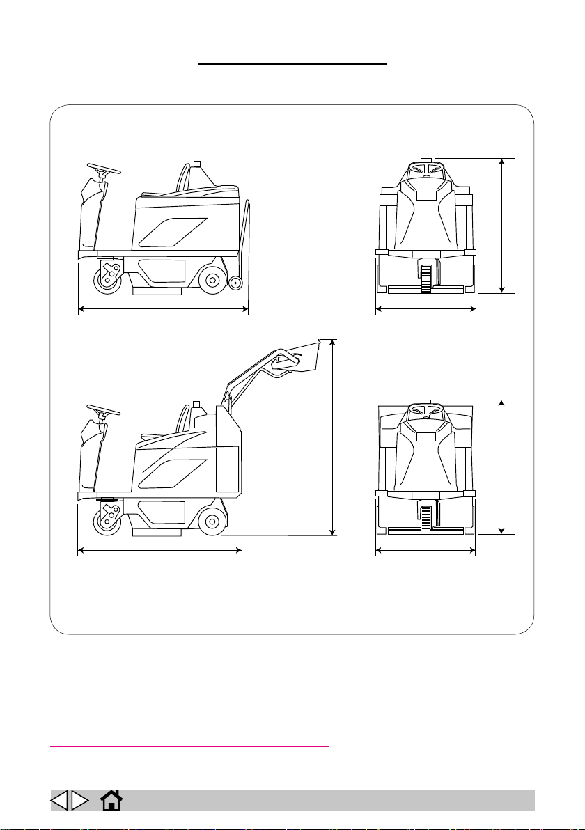
MACHINE DIMENSIONS
Y
X
X
Z
Y1
Y2
Z
X-Y-Z: See “TECHNICAL CHARACTERISTICS” table
ITGB
7
Page 8
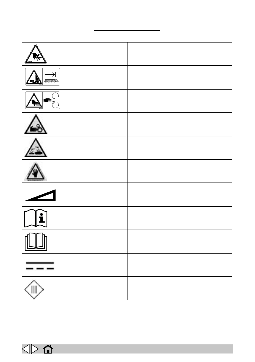
SAFETY SYMBOLS
WARNING! RISK OF CUTTING
WARNING! RISK OF CRUSHING LIMBS
WARNING! RISK OF ABRASION
WARNING! RISK OF ENTANGLEMENT
WARNING! RISK OF ACID BURNS
WARNING! RISK OF BURNS
MAXIMUM SLOPE
OPERATOR’S MANUAL, OPERATING INSTRUCTIONS
READ THE OPERATOR’S MANUAL
DIRECT CURRENT SYMBOL
INSULATION CLASS, THIS CLASSIFICATION ONLY APPLIES TO MACHINES POWERED BY BATTERIES.
GB
8
Page 9
GENERAL INFORMATION
Purpose of this manual
This manual has been written by the Manufacturer and is an integral part of the machine1.
It denes the purpose for which the machine has been designed and constructed and contains all
the information required by operators2.
In addition to this manual, which contains information for operators, other publications are available
providing specic information for maintenance personnel3.
The terms “right” and “left”, “clockwise” and “anti-clockwise” refer to the forward movement of the
machine.
Constant compliance with the instructions provided in this manual guarantees the safety of the op-
erator and the machine, ensures low running costs and high quality results and extends the working
life of the machine. Failure to follow these instructions may lead to injury to the operator or damage
to the machine, oor and environment.
Consult the table of contents at the beginning of the manual to nd the section you need rapidly.
Parts of the text requiring special attention are printed in bold and preceded by the symbols illus-
trated and described here.
Indicates the need for attention in order to avoid a series of consequences which could cau-
se death or serious injury to personnel.
! DANGER!
Indicates the need for attention in order to avoid a series of consequences which could
! WARNING!
cause injury to personnel or damage to the machine or work environment or nancial loss.
! IMPORTANT!
Important information.
In line with the company’s policy of constant product development and updating, the Manu-
facturer reserves the right to make modications without prior notice.
Although your machine may dier appreciably from the illustrations in this document, the
correctness and validity of the instructions contained in this manual are guaranteed.
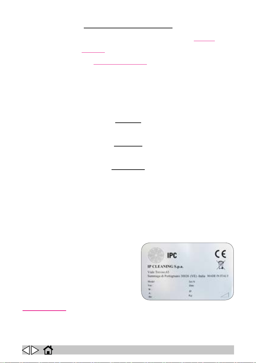
Identifying the machine
The nameplate provides the following information:
► Model
► Battery voltage
► Total rated power
► Rated current draw
► Serial number
► Year of manufacture
► IP Index of Protection
► Dry weight
► Maximum negotiable gradient
► Name of manufacturer
1 The term "machine" replaces the trade name of the machine described in this manual.
2 Persons responsible for operating the machine but not for performing maintenance operations requiring special
technical skills.
3 Persons with technical experience, training and a knowledge of applicable legislation and standards, able to perform
all necessary operations and to recognise and avoid possible risks in handling, installing, operating and maintaining the
machine.
GB
9
Page 10

Documentation provided with the machine
► Operator’s manual
► Certicate of warranty
► CE certicate of conformity
GB
10
Page 11
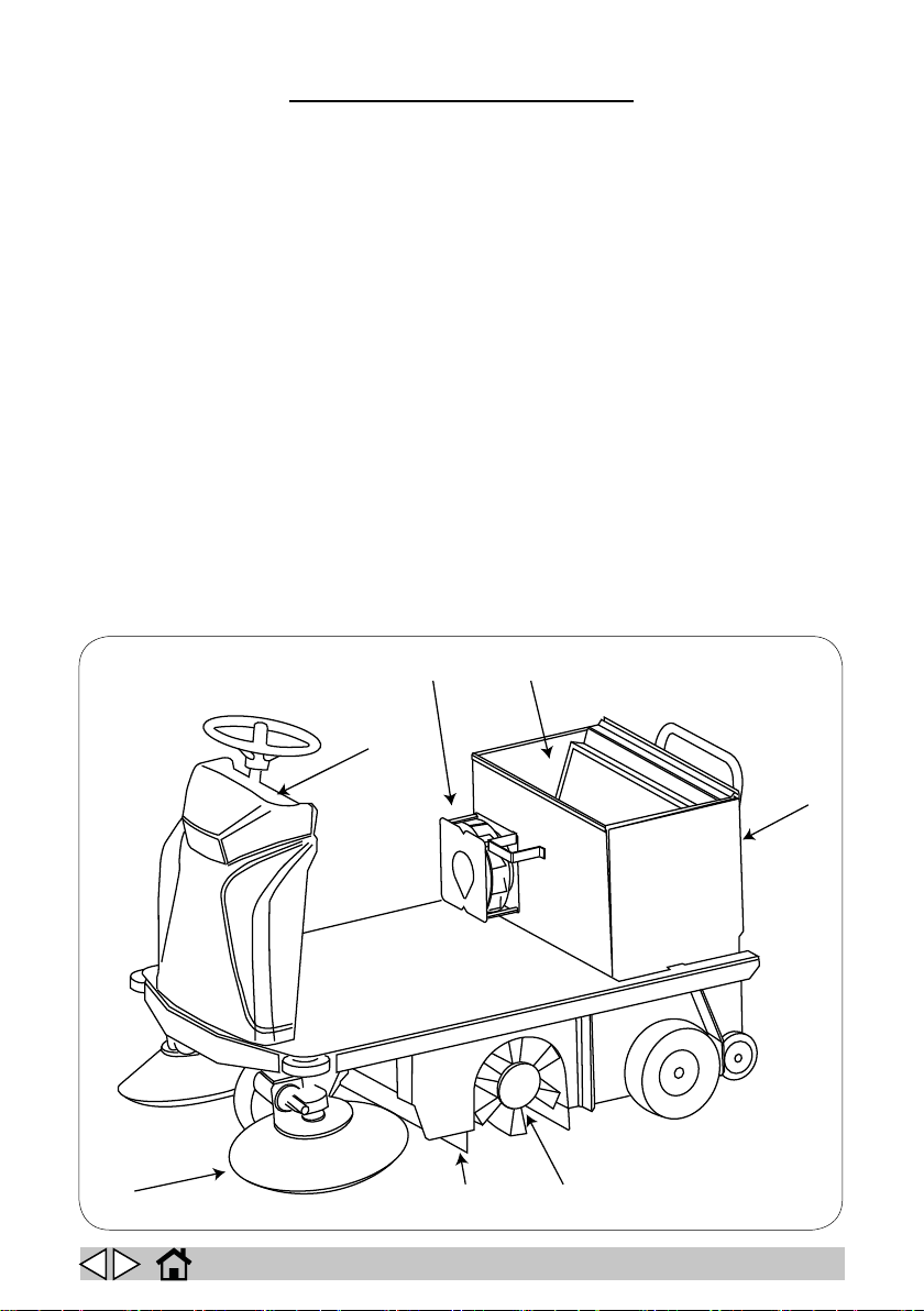
TECHNICAL INFORMATION
1
2
5
6
37
4
General description
The machine described in this manual is a motorised sweeper designed to sweep oors in civil and
industrial premises.
It may be used to clean the residues of industrial processes, dust and dirt in general on all relatively
even, at and hard surfaces such as concrete, asphalt, porcelain stoneware, ceramic tiles, sheet
metal, marble, embossed or smooth rubber or plastic mats indoors or outdoors.
Parts of the machine
The machine comprises the main parts described below (g. 1).
► Debris bin (1, g. 1). This collects the debris picked up by the main brush and dust from
the lter.
► Control panel (2, g. 1).
► Main brush (3, g. 1). This is the most important part of the machine, and transfers dust
and debris to the bin. Brushes are available in dierent hardnesses and with dierent bri-
stles to suit the type of material to be picked up.
► Side brushes (4, g. 1). These convey dust and debris towards the main brush. They only
clean edges, corners and proles.
► Suction lter (5, g. 1). This lters the air drawn in by the suction fan.
► Suction fan (6, g. 1). This enables the machine to sweep without raising dust.
► Flaps (7, g. 1). These surround the main brush and maintain the suction created by the
fan.
1
GB
11
Page 12

Hazard areas
► Control panel: risk of injury from short circuits.
► Main brush: risk of injury by rotating brush.
► Side brushes: risk of injury by rotating brushes.
► Front/rear wheels: risk of crushing between the wheels and chassis.
► Motor/engine/battery compartment: risk of injury from short circuits between battery poles;
risk of serious burns if maintenance is performed with the engine o but still hot (Petrol and
Dual Power versions).
► Debris bin: risk of crushing during lifting/lowering and rotation.
Accessories
► Soft, hard and abrasive brushes.
GB
12
Page 13

SAFETY INFORMATION
Safety precautions
Read this Operator’s Manual carefully before start-up and use and before performing any
maintenance or other work on the machine.
Rigorously follow all the instructions in this Operator’s Manual (in particular those marked
“Danger!” and “Warning!”. Also respect the safety labels applied to the machine (see the
The Manufacturer declines all liability for injury to persons or damage to property resulting
from failure to follow instructions.
When the seat cowling is raised, the gas spring (if tted) must be locked in place, turning the
green ring nut to the position marked with the closed padlock, so as to prevent the cowling
The machine must be used exclusively by persons trained in its use and/or who have demonstrated
their ability and have been expressly authorised to use it.
The machine must not be used by minors.
The machine must not be used for purposes other than those for which it was expressly designed.
Scrupulously respect all safety standards and conditions applicable to the type of building in which
the machine is to be operated (e.g.: pharmaceutical companies, hospitals, chemicals, etc.).
Do not use the machine in inadequate lighting, explosive atmospheres, on public roads, to clean dirt
that is hazardous to health (dust, gas, etc.) or in unsuitable environments.
The machine is designed to operate in temperatures between +4°C and +40°C. It can be stored in
temperatures between +0°C and +50°C when not in use.
The machine is designed to operate at relative humidity levels between 30% and 95%.
Never use the machine to clean up ammable or explosive liquids (e.g. petrol, fuel oil, etc.), acids or
solvents (e.g. paint solvents, acetone etc.) even if diluted. Never clean up burning or incandescent
objects.
Never use the machine on slopes or ramps of more than 12%. Never drive across even gentle
slopes. Always manoeuvre with care and avoid reversing. When transiting steeper ramps or slopes,
take the utmost care to prevent tipping and/or uncontrolled acceleration.
Never park the machine on a slope.
Never leave the machine unattended with the motor or engine on. Before leaving it, turn the motor
or engine o and make sure it cannot move accidentally.
Always pay attention to other people, especially children, in the place where you are working.
Children must be supervised to make sure they do not play with the machine.
The machine is not intended for use by persons (including children) with reduced physical, sensory
or mental capabilities, or lack of experience and knowledge, unless they are supervised by a person
responsible for their safety and have received instruction in the use of the machine.
Never use the machine to transport people or goods or to tow things.
Do not tow the machine.
Never rest objects of any weight on the machine for any reason.
Never obstruct the ventilation and heat dispersion openings.
Never remove, modify or circumvent safety devices.
Numerous unpleasant experiences have shown that a wide range of personal objects may cause
serious accidents. Before beginning work, remove jewellery, watches, ties, etc..
The operator must always use personal protection devices: protective apron or overalls, non-slip
waterproof shoes, rubber gloves, protective goggles and ear protectors and mask to protect the
respiratory tract.
Keep hands away from moving parts.
Make sure the power sockets used for the battery charger are connected to a suitable earth system
and protected by thermal magnetic and earth leakage breakers.
Make sure the electrical characteristics of the machine (voltage, frequency, power) given on the
! DANGER!
! WARNING!
“Safety symbols” section.
! DANGER!
from closing accidentally.
GB
13
Page 14

nameplate correspond to those of the mains electricity supply.
It is indispensable to respect the battery manufacturer’s instructions and applicable legislation. The
batteries should always be kept clean and dry to avoid surface leakage current. Protect the batter-
ies from impurities such as metal dust.
Never rest tools on the batteries as they could cause short circuits leading to explosions.
When using battery acid, always follow scrupulously the safety instructions given in the “Batteries:
preparation” section.
Battery charger ( OPTIONAL ): check the power cable regularly for damage. If the power cable is
damaged, do not use the charger.
If particularly strong magnetic elds are present, assess their possible eect on the control electron-
ics.
Never wash the machine with water jets.
In the case of malfunction and/or faulty operation, turn the machine o immediately (disconnecting
it from the mains power supply or batteries) and do not tamper with it. Contact a service centre
authorised by the Manufacturer.
The debris bin raising and release/tipping lever area is a “danger zone”. Keep away during the
relevant movements.
The motor/battery area is a “danger zone”. The machine must be o and the emergency button
pressed before access.
All maintenance operations must be performed in an adequately illuminated area and only after
disconnecting the machine from the power supply.
All work on the electrical system and all maintenance and repair operations other than those
explicitly described in this manual must be performed by specialist and experienced personnel
only.
Only use original accessories and spare parts supplied by the Manufacturer to guarantee safe and
problem-free operation of the machine. Never use parts removed from other machines or from
other kits.
The machine is designed and constructed to provide ten years’ service from the date of manufacture
shown on the nameplate. After this period, whether the machine has been used or not, it should be
disposed of according to current legislation in the country in which it is used.
It should be disconnected from the power supply, emptied of all liquids and cleaned prior to disposal.
The machine is classied as WEEE type special waste and is covered by the requirements of applicable environmental protection regulations (2002/96/EC WEEE).
The machine must be disposed of separately from ordinary waste in compliance with current legislation and standards.
If you decide to stop using the machine, remove the batteries and dispose of them through an au-
thorised recycling centre.
You should also make sure that all parts of the machine that could represent a hazard, particularly
to children, are made safe.
Alternatively, return the machine to the Manufacturer for a complete overhaul.
GB
14
Page 15

MOVEMENT INSTALLATION
Lifting and transporting the packaged machine
During all lifting operations, make sure the packaged machine is rmly secured to avoid it
tipping up or being accidentally dropped.
Always load/unload lorries in adequately illuminated areas.
The machine is packaged on a wooden pallet by the Manufacturer. It must be loaded on to the transporting vehicle using suitable equipment (see EC Directive 89/392 and subsequent amendments
and/or additions). At destination, it must be unloaded using similar means.
A fork lift truck must always be used to lift the packaged body of the machine. Handle with care to
avoid knocking or overturning the machine.
Delivery checks
When the carrier delivers the machine, make sure the packaging and machine are both whole and
undamaged. If the machine is damaged, make sure the carrier is aware of the damage and before
accepting the goods, reserve the right (in writing) to request compensation for the damage.
! WARNING!
Unpacking
When unpacking the machine, the operator must be provided with the necessary personal
protection devices (gloves, goggles, etc.) to limit the risk of injury.
Proceed as follows to unpack the machine.
► Cut and remove the plastic straps using scissors or nippers.
► Remove the cardboard packaging.
► Remove the bags from the battery compartment and check their contents:
this Operator’s Manual, the maintenance manual, declaration of conformity, certicate of
warranty; battery bridges with terminals; connector for battery charger.
Depending on the model, remove the metal brackets or cut the plastic straps xing the machine
chassis to the pallet.
Using a sloping ramp, push the machine backwards o the pallet.
Unpack the brushes from their packaging.
Clean the outside of the machine, taking care to respect safety regulations.
Once the machine is clear of the packaging, proceed to install the batteries (see the “Batteries:
installation and connection” section).
The packaging may be kept and reused to protect the machine if it is moved to another site or to a
repair workshop.
Otherwise it must be disposed o in compliance with current legislation.
! WARNING!
Batteries (Battery version)
Two dierent types of battery may be installed on these machines:
► Leak-proof tubular batteries: these require regular checks on electrolyte level. When nec-
essary, top up with distilled water until the plates are covered. Do not over-ll (5 mm max.
above the plates).
► Gel batteries: this type of battery requires no maintenance.
Battery technical characteristics must correspond to those listed in the Technical characteristics
section. The use of higher capacity batteries could seriously jeopardise manoeuvrability and lead to
the drive motor overheating. Batteries with a lower capacity and weight will require charging more
frequently.
Batteries must be kept charged, dry and clean and the connections must be kept tight.
GB
15
Page 16
Follow the instructions below to congure the machine’s software for the type of batteries
+
+
+
+
+
-
-
-
-
-
Battery
+
-
-
-
+
+
Dual Power
see the “Technical menu section”.
! IMPORTANT!
installed:
Batteries: preparation
During battery installation and any type of battery maintenance, the operator must be provided with the necessary personal protection devices (gloves, goggles overalls, etc.) to limit
the risk of injury. Keep clear of naked ames, avoid short circuiting the battery poles, avoid
Batteries are normally supplied lled with acid and ready for use.
If the batteries are dry, proceed as follows before installing them in the machine.
Remove the caps and ll all elements with sulphuric acid solution specic for batteries until the
plates are entirely covered (this requires at least a couple of passes for each element).
Leave the batteries stand for 4-5 hours to allow air bubbles to come to the surface and the plates
to absorb the electrolyte.
Make sure the level of electrolyte is still above the plates and if necessary top up with sulphuric
acid solution.
Close the caps.
Install the batteries in the machine (following the procedure described below).
Charge the batteries before starting up the machine for the rst time. Follow the instructions in the
“Battery maintenance and charging” section.
! DANGER!
sparks and do not smoke.
Batteries: installation and connection
Make sure you connect the terminals marked with a “+” to the positive poles of the battery.
Meticulously follow the instructions given below as short circuiting the batteries could
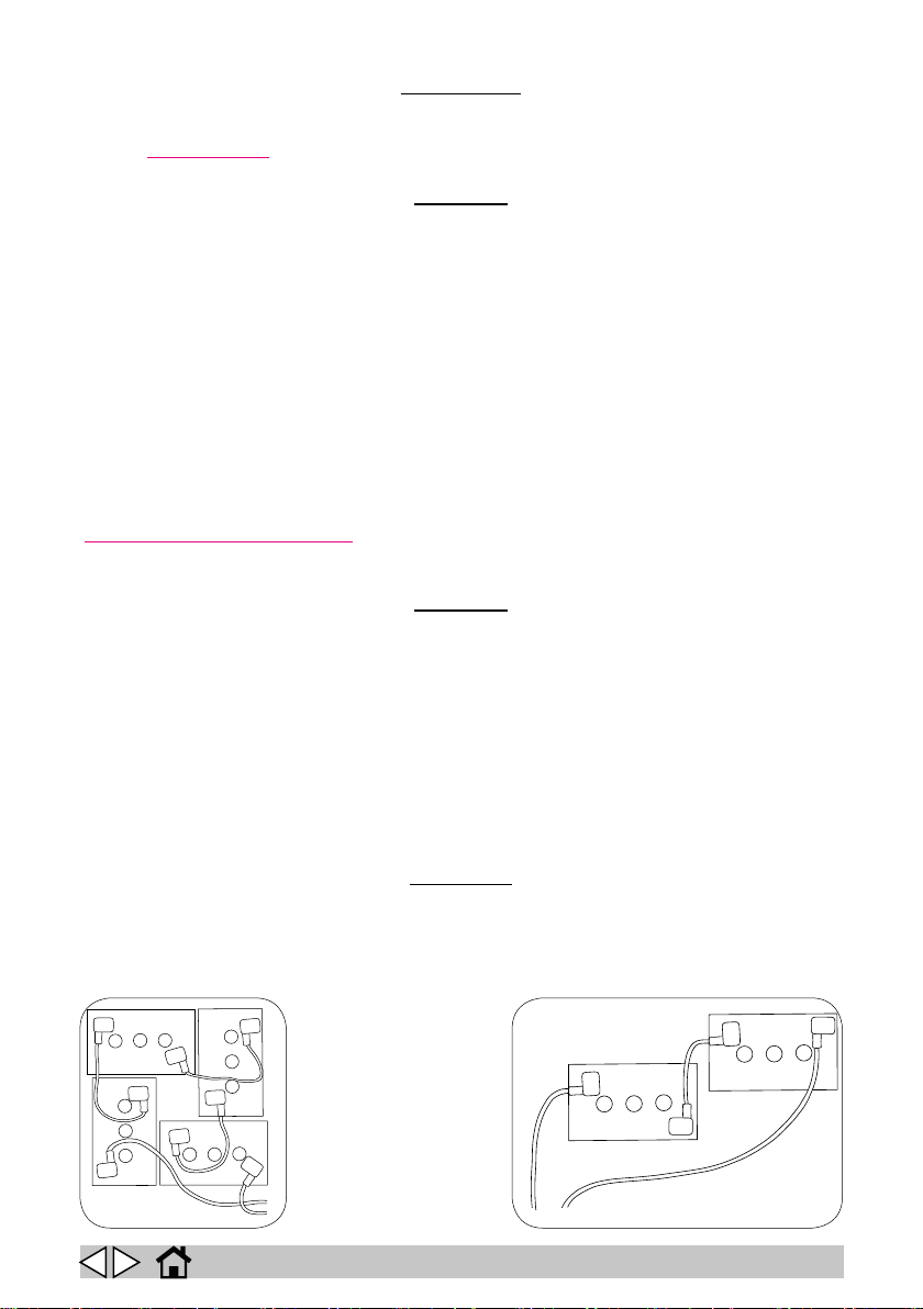
Place the batteries in the battery compartment, orienting them as shown in the drawings (gs. 2
and 3).
Referring to the cable layout shown in the above diagram, connect the battery cables and bridge
terminals to the battery poles. Arrange the cables as shown in the diagram, tighten the terminals on
the poles and coat with Vaseline.
Lower the cowling into the working position
When using the machine, follow the instructions below.
Never allow the batteries to become excessively at as this could damage them irreparably.
Check that all switches on the control panel are in the “0” (o) position.
Do not check the battery charge by sparking.
3
! DANGER!
cause them to explode.
! WARNING!
2
GB
16
Page 17

Batteries: removal
When removing the batteries, the operator must be equipped with suitable personal protection devices (gloves, goggles, overalls, safety shoes, etc.) to reduce the risk of injury. Make
sure the switches on the control panel are in the “0” position (o) and the machine is turned
o. Keep away from naked ames, do not short circuit the battery poles, do not cause sparks
and do not smoke. Proceed as follows.
► Disconnect the battery cables and bridge terminals from the battery poles.
► If necessary, remove the devices xing the battery to the base of the machine.
► Lift the batteries from the compartment using suitable lifting equipment.
! DANGER!
Choosing a battery charger
Make sure the battery charger is compatible with the batteries to be charged.
Tubular lead batteries: an automatic charger is recommended. Consult the battery charger manufacturer and manual to conrm the choice.
Gel batteries: use a charger specic for this type of battery.
Preparing the battery charger
If you wish to use a battery charger not provided with the machine, you must t it with the connector
supplied with the machine.
Proceed as follows to t the connector.
Remove about 13 mm of protective sheath from the red and black cables of the battery charger.
Insert the wires into the connector contacts and squeeze them forcefully with suitable pliers.
Respect the polarity (red wire + black wire –) when inserting the wires into the connector.
Preparing the engine (Petrol and Dual Power versions)
► Fill the fuel tank.
► Check the engine oil level.
Preparing the hydraulic circuit (Petrol and Diesel versions)
► Check the hydraulic oil level.
Fitting the side brushes
See the “Replacing/installing the side brushes” section.
GB
17
Page 18

Follow the instructions given below to congure the machine’s control software to use the
See the “Technical menu” section.
! IMPORTANT!
display language you require.
Lifting and transporting the machine
All phases of lifting and moving must be performed in an adequately illuminated environ-
ment with the adoption of the safety measures most appropriate to the situation.
The operator must always use personal protection devices.
Proceed as follows to load the machine onto a means of transport.
► Empty the debris bin.
► Remove the batteries.
► Position the machine on a pallet and x it in place with plastic straps or metal brackets.
► Lift the pallet (with the machine) using a fork lift truck and load it onto the means of trans-
port.
► Anchor the machine to the means of transport with cables connected to the pallet and to
the machine itself.
! WARNING!
GB
18
Page 19

PRACTICAL GUIDE FOR THE OPERATOR
Before starting work, wear overalls, ear protectors, non-slip and waterproof shoes, mask to
protect the respiratory tract, gloves and all other personal protection devices necessitated
Do not leave the machine unattended or parked with the key in the switch and the parking
If you are using the machine for the rst time, we recommend trying it out on a large obsta-
cle-free surface rst to acquire the necessary familiarity.
Do not use the machine to clean up wire, string, plastic straps, water or other liquids.
When picking up large but light objects (e.g. paper, leaves, etc.) raise the aps.
To avoid damaging the surface of the oor you are cleaning, avoid rotating the brushes with
Each 30 minutes of work, press the lter shaker button for 30 seconds to clean the suction
lter. During this operation, the suction fan shuts o automatically (Battery and Dual Power
Avoid passing over puddles of water. If the oor is wet, you can still use the machine, but
you must turn o the suction fan since damp/wet dirt reduces the performance of the suc-
For best results, empty the debris bin often and use the lter shaker frequently to keep the
The machine is tted with a driver detection device. It is only possible to start the machine
while seated correctly in the driving seat. The device halts the machine if you get up from
! WARNING!
by the work environment.
! WARNING!
brake o.
! IMPORTANT!
! WARNING!
! IMPORTANT!
! WARNING!
the machine stationary.
! WARNING!
versions).
! WARNING!
tion lter.
! WARNING!
lter clean.
! IMPORTANT!
the seat.
Preparing the machine for work
Proceed as follows before starting work.
► Check the battery charge level (and recharge if necessary). On Petrol and Dual Power
versions, check whether the fuel tank needs topping up.
► Make sure the debris bin is empty. If necessary, empty it.
GB
19
Page 20
Controls of the Battery and Dual Power versions
1
2
3
4
5
1
1
2
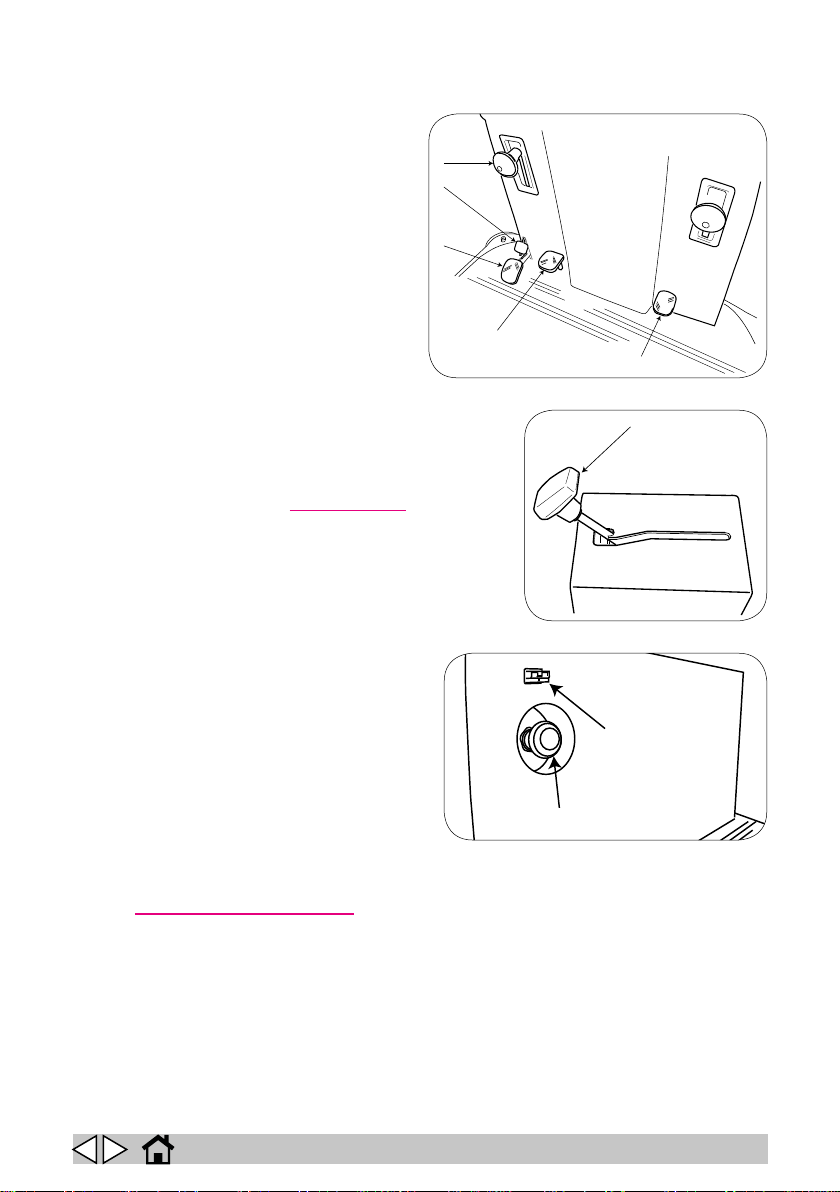
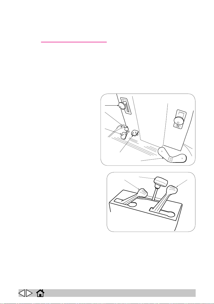
► Brake lock pedal (2, g. 4): Press
this pedal along with the service brake
pedal to engage the parking brake. To
disengage the brake lock and release
the parking brake, simply press the ser-
vice brake pedal.
► Service brake pedal (3, g. 4): Press
this pedal to stop the machine during
operation.
► Flap lift pedal (4, g. 4): Press this
pedal to lift the aps in order to pick
up large but light objects. Release the
pedal when not needed.
► Accelerator pedal (5, g. 4): Press
this pedal to control the speed of the
machine. If the accelerator pedal is released for more than three seconds while the machine is switched on, the “ AUTO POWER-OFF” function switches o all machine functions. To start again,
simply press the accelerator pedal. You can enable/
disable and change the delay for “ AUTO POWEROFF” mode from the “Technical menu”.
► Left and right side brush control lever (1, g. 4):
Push this lever down to lower the side brushes to
working position and start rotation. Raise the lever to
lift the brushes and stop rotation.
► Main brush control lever (1, g. 5): Push this lever
forwards to lower the main brush to working position
and start rotation. Raise the lever again
to lift the brushes and stop rotation on
completion of work. The suction fan starts
automatically when the main brush starts
rotating.
► Emergency stop button (1, g. 6):
Press this mushroom head button in the
event of imminent danger or need to deactivate all machine functions and dis-
connect power to the machine. Switch o
all the previously active functions (side
brushes, main brush) before resetting the
emergency stop button.
► Battery charger socket (2, g. 6): Plug the battery charger into this socket. See the
”Preparing the battery charger” section.
4
5
6
GB
20
Page 21
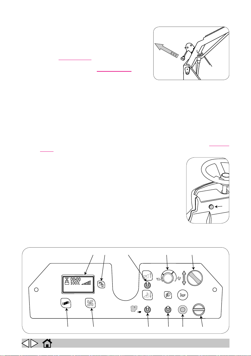
► Bin tipping lever (top unloading) (g. 7): Pull this
1
2
0
1
START
00:00
100%
1 2 3 4 5
6 7 8 9 10 11
7
lever to rotate the bin and empty its contents.
► Display (1, g. 8): This displays the current battery
charge level expressed as a percentage, logos for
active functions, an hour counter showing the total
hours of use of the machine and any active alarms,
see the “Display alarms ” section.
► Menu button (2, g. 8): On the Battery version, this
button is only active in the “Technical menu”. On the
Dual Power version, it serves to display the hours of
functioning of the engine.
► Bin up/down switch (3, g. 8): Lifts or lowers the debris bin.
► Speed control (4, g. 8): Regulates the forward and reverse speed of the machine.
► Direction selector (5, g. 8): Turn this selector to engage forward or reverse travel.
► Main switch (6, g. 8): Switches power to all machine functions on/o.
► Horn button (7, g. 8): Press to sound the horn.
► Light switch (8, g. 8): Turns the lights (OPTIONAL) on and o.
► Engine start switch (9, g. 8): Starts and shuts down the engine.
► Suction switch (10, g. 8): Switches suction on and o.
► Filter shaker button (11, g. 8): Press and hold this button for 30 seconds to shake and
clean the suction lter. As soon as the shaker motor starts, the suction and drive motors
are switched o. You can select the “automatic lter shaker” function from the “Technical
menu”. When this function is active, the lter shaker is automatically
switched on at the end of the set interval.
29
► Bin up/down movement enabling button (1, g. 29): Press this
button to enable bin movement by the bin up/down switch.
8
GB
21
Page 22
Operating the Battery and Dual Power versions
1
2
3
4
5
1
2
3
► Sit correctly in the seat.
► Turn the main switch to position “1”.
► Check that the display shows the batteries to be fully charged. Recharge if necessary. See
the “Battery maintenance and charging” section.
► Select the direction of travel with the direction selector.
► Release the parking brake.
► Lower the side brushes.
► Lower the main brush.
► Press the accelerator pedal to move o and start work.
► Press the ap lift pedal only when you need to pick up large but light objects.
► Cleaning quality depends largely on the cleanliness of the suction lter. Operate the lter
shaker at intervals suitable to the environment in which you are using the machine.
Controls of the Petrol and Diesel versions
► Brake lock pedal (2, g. 9): Press
this pedal along with the service
brake pedal to engage the parking
brake. To disengage the brake lock
and release the parking brake,
simply press the service brake
pedal.
► Service brake pedal (3, g. 9):
Press this pedal to stop the ma-
chine during operation.
► Flap lift pedal (4, g. 9): Press
this pedal to lift the aps in order to
pick up large but light objects. Release the pedal when not needed.
► Direction selector pedal (5, g.
9): Press this pedal to select the
direction and the speed of travel.
► Left and right side brush control
lever (Fig. 9-Ref. 1): Push this lever
down to lower the side brushes to the
working position. When the combus-
tion engine is running, the brush spins
continually, both in the working and
rest positions.
► Main brush control lever (Fig. 10-
Ref. 2):): Push this lever forwards to
lower the main brush to the working
position. When the combustion engine
is running, the brush spins continually,
both in the working and rest positions.
► Suction control level (1, g. 10): Adjust this lever to increase or reduce suction.
► Engine drive lever (3, g. 10): Enables/disables all functions powered by the engine.
9
10
GB
22
Page 23
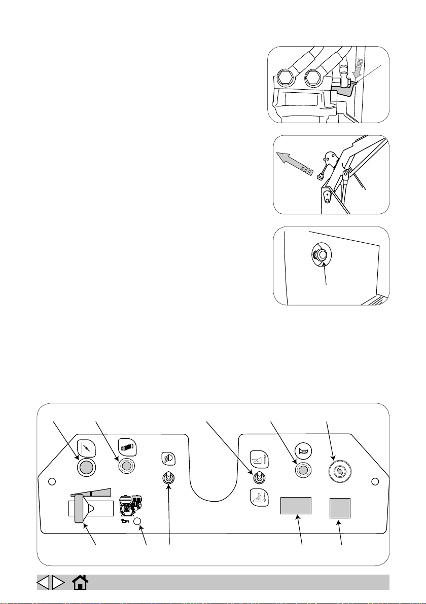
► Emergency bypass (1, g. 11): Use this lever to
O
F
F
O
N
S
T
A
R
T
2 3 4 5
6 7 8
9 10
1
1
1
move the machine with the engine o. Press in the
direction shown to disengage the hydraulic pump.
► Bin tipping lever (top unloading) (g. 7): Pull this
lever to rotate the bin and empty its contents.
► Emergency stop button (1, g. 12): Press this
mushroom head button in the event of imminent danger or need to deactivate all machine functions and
disconnect power to the machine.
► Choke (1, g. 13): Pull to engage the choke for cold
starting (PETROL VERSION).
► Filter shaker button (2, g. 13): Shut o suction with
the suction control lever and then press and hold this
button for 30 seconds to shake and clean the suction
lter.
► Bin up/down switch (3, g. 13): Lifts or lowers the
debris bin.
► Horn button (4, g. 13): Press to sound the horn.
► Main switch (5, g. 13): Switches power to all machine
functions on/o.
► Voltage indicator (6, g. 13): Shows correct electric
circuit voltage.
► Hour counter (7, g. 13): Shows machine operating
hours.
► Engine speed control lever (8, g. 13): Move this le-
ver to adjust engine speed.
11
7
12
13
GB
23
Page 24
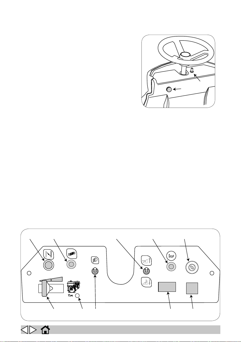
► Light switch (Fig. 13-Ref. 9): used to switch the
1
2
O
F
F
O
N
S
T
A
R
T
2 3 4 5
6 7 8
9 10
1
lights on and o (OPTIONAL)
► “Oil alert” light (Fig. 13-Ref.10): engine oil
pressure problem.
► Bin up/down movement enabling button (1,
g. 29): Press this button to enable bin move-
ment by the bin up/down switch.
29
13
GB
24
Page 25
Operating the Petrol and Diesel versions
► Sit correctly in the seat.
► Release the parking brake.
► Move the engine speed control lever to START position.
► Pull out the choke (PETROL VERSION).
► Move the engine drive lever to position 1-START and hold it there while turning the ignition
key to START position.
Do not engage the starter motor for more than ve seconds at a time. If the engine fails to
start, release the ignition key and wait ten seconds before trying again.
► Allow the ignition key to return to ON position as soon as the engine starts and release the
engine drive lever.
► Press on the direction selector pedal to move o. Press the right side to move forwards.
Press the left side to move backwards.
► Lower the side brushes.
► Lower the main brush.
► Adjust the suction control lever to obtain the required strength of suction.
► Press the ap lift pedal only when you need to pick up large but light objects.
► Cleaning quality depends largely on the cleanliness of the suction lter. Operate the lter
shaker at intervals suitable to the environment in which you are using the machine.
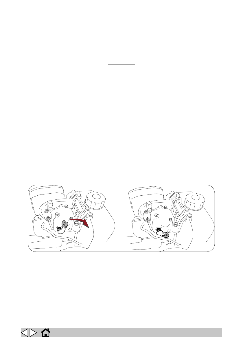
If the DIESEL engine fails to start due to a starter motor malfunction, proceed as follows:
lower the lever highlighted in the gure (Fig. 30) on the motor head and try to start the en-
! WARNING!
! WARNING!
gine again.
30
GB
25
Page 26
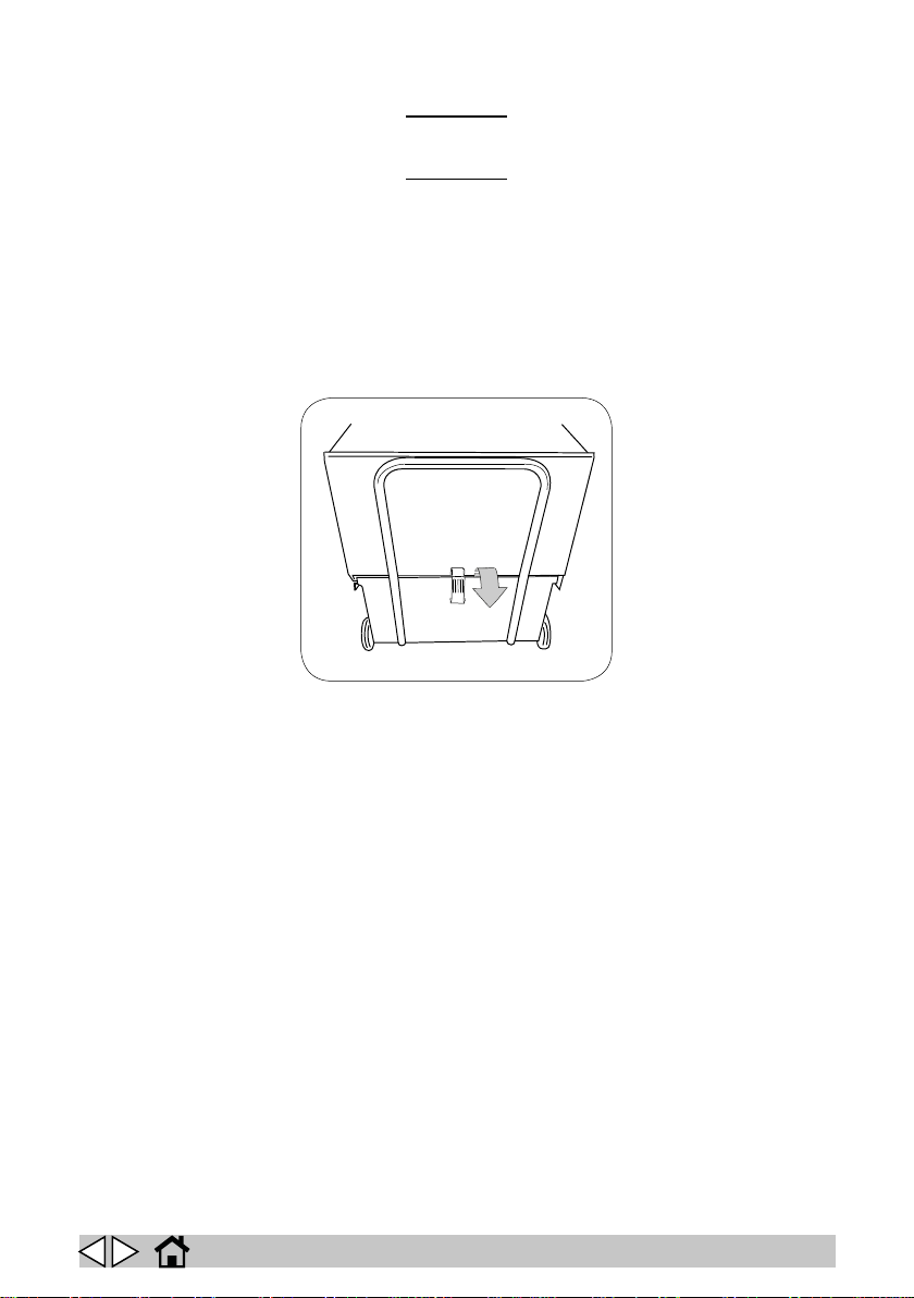
Emptying the bottom unloading debris bin
When emptying the bin, always wear a mask to protect the respiratory tract from the dust
which is always present during this operation.
Before emptying the debris bin, operate the lter shaker for 30 seconds to clean the lter
► Release the bin lock (g. 14).
► Pull out the rear bin by means of its handle.
► Take the bin (which is tted with wheels) to the rubbish collection point and empty it.
! WARNING!
! WARNING!
14
GB
26
Page 27
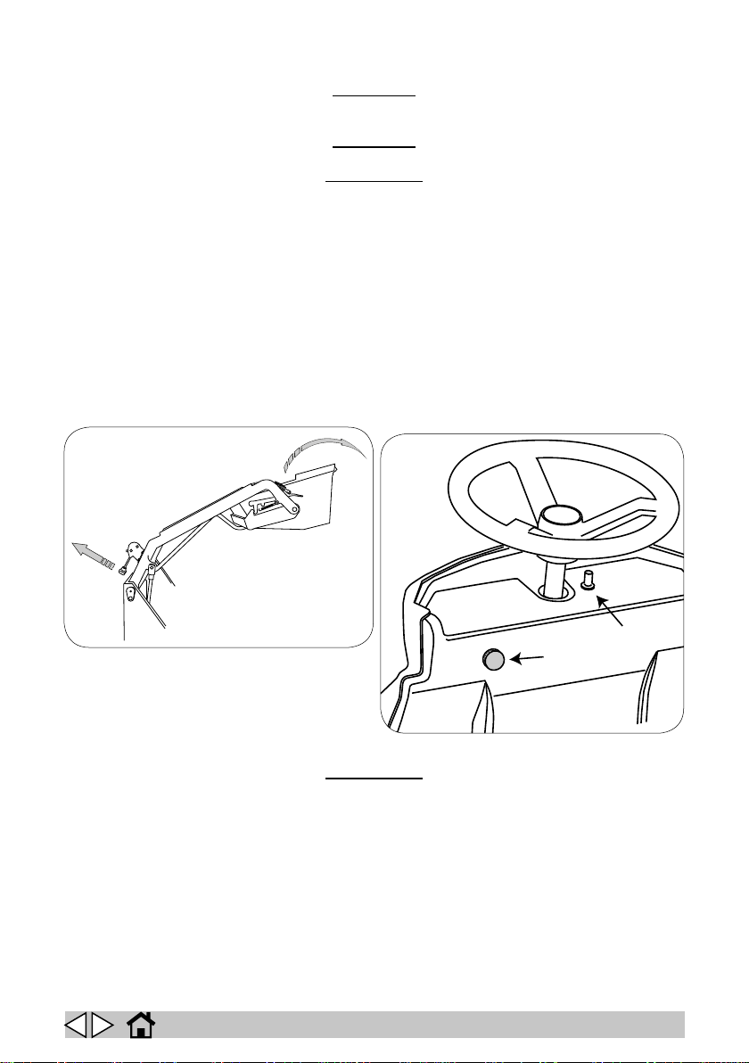
Emptying the top unloading debris bin
1
2
When emptying the bin, always wear a mask to protect the respiratory tract from the dust
which is always present during this operation.
Before emptying the debris bin, operate the lter shaker for 30 seconds to clean the lter
When you open the bin, all functions are disabled on Battery and Dual Power versions, and
the engine is also switched o on the Dual Power version.
► Press and hold the bin movement enabling button (1, g. 29) then operate the bin up/down
switch (2, g. 29) to raise the bin to the required height.
► Pull the lever (g. 7) to rotate the bin and empty its contents.
► Turn the bin back to its horizontal position.
► Press and hold the bin movement enabling button (1, g. 29) then operate the bin up/down
switch (2, g. 29) to lower the bin again.
! WARNING!
! WARNING!
! IMPORTANT!
7
29
Finishing work
Shake the lter at the end of every work session.
When you nish work, switch the machine o at the main switch, lift the side brushes and main
brush and engage the parking brake.
! IMPORTANT!
Moving the machine when not in operation
Proceed as follows to move the machine.
► Raise the side brushes.
► Raise the main brush.
► Select the direction of travel.
► Press the accelerator pedal.
GB
27
Page 28

Proceed as follows to prepare the machine for extended periods of inactivity.
PERIODS OF INACTIVITY
► Empty the debris bin.
► Clean the suction lter.
► Disconnect the machine from the power supply.
► Completely recharge the batteries and deposit them in the battery store. During long peri-
ods of inactivity, you should charge the batteries regularly (at least once every two months)
to keep them constantly at maximum charge.
If you do not charge the batteries regularly, they may be irreparably damaged.
! WARNING!
GB
28
Page 29
MAINTENANCE INSTRUCTIONS
Never perform any maintenance operations without rst disconnecting the batteries.
Maintenance of the electrical circuit and all other operations not expressly required by this
manual must be performed by specialised personnel only, in compliance with current safety
legislation and as described in the maintenance manual.
Maintenance - General rules
Performing regular maintenance according to the Manufacturer’s instructions improves performance and extends the working life of the machine.
When cleaning the machine, observe the following precautions.
► Avoid using pressure washers. Water could penetrate the electrical compartment or mo-
tors leading to damage or short circuits.
► Do not use steam to avoid the heat warping plastic parts.
► Do not use solvents or hydrocarbon based products. These can damage the cowling and
rubber components.
Replacing/installing the main brush
This operation must be performed with the machine switched o and the key removed.
Proceed as follows to replace the main brush.
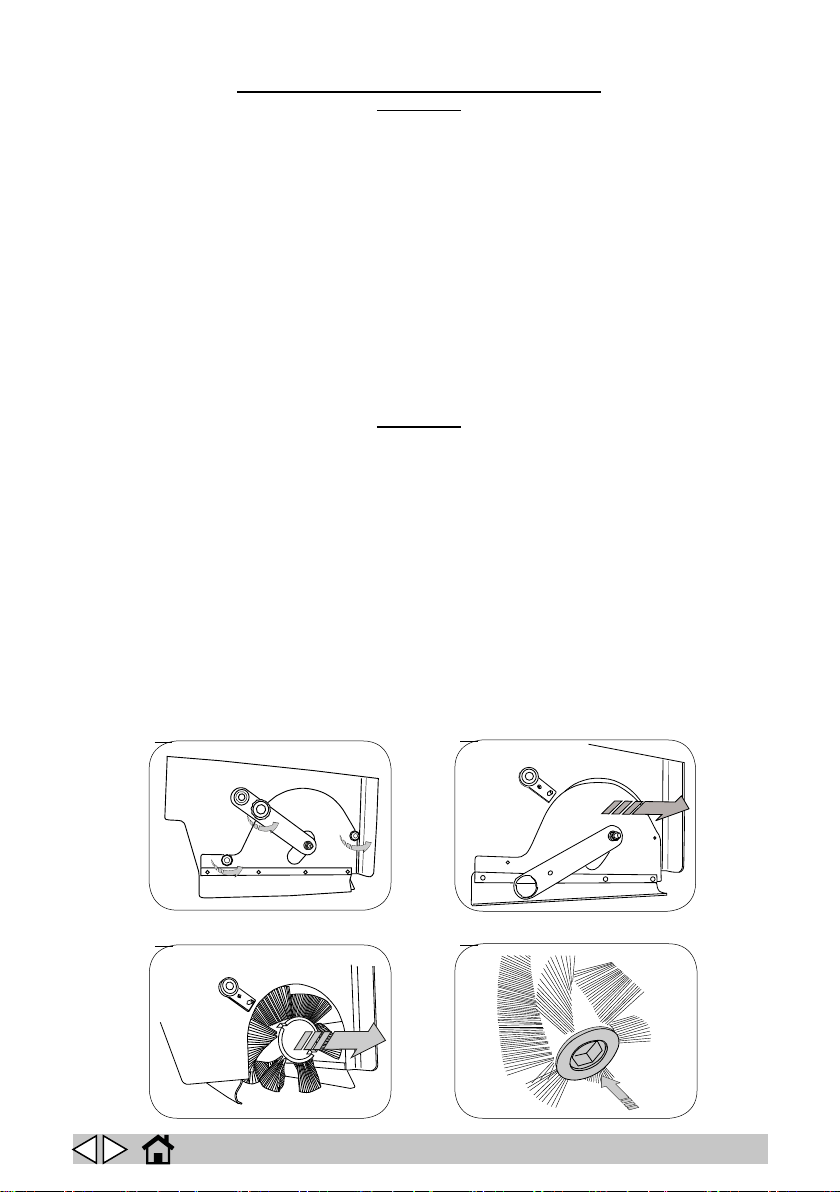
► Unscrew the knob and open the door on the left of the machine.
► Unscrew the three knobs securing the brush compartment cover (g. 15).
► Remove the brush compartment cover (g. 16).
► Pull out the brush (g. 17).
► Remove the adapter from the core of the old brush and t it to the new brush, taking care
to keep the bristles aligned in the same direction (g. 18).
► Fit the adapter with the new brush in the machine, taking care to ensure that the adapter
engages the drive hub securely. Fit the cover over the brush compartment and x it in place
with the three knobs removed previously.
! DANGER!
! DANGER!
15
17
GB
16
18
29
Page 30
Adjusting the main brush
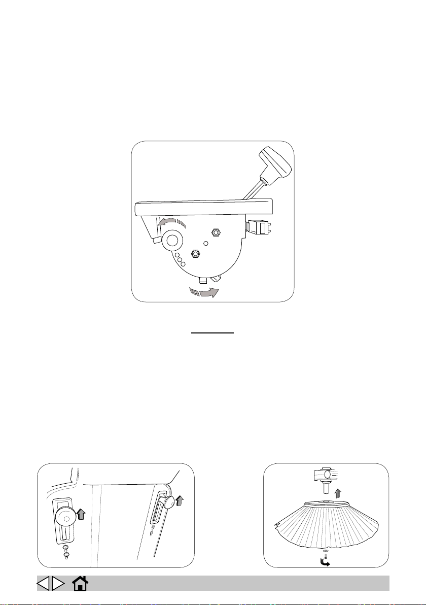
The main brush makes a major contribution to the eciency of the whole machine. Correct adjust-
ment ensures better quality cleaning in shorter times.
The machine is delivered correctly adjusted. The main brush therefore only needs further adjust-
ment when it becomes worn. Proceed as follows to adjust the main brush.
► Unscrew the knob (g. 19).
► Turn the adjuster anti-clockwise until the knob xing hole can be engaged (g. 19).
► Screw the knob back in (g. 19).
19
Replacing/installing the side brushes
! DANGER!
This operation must be performed with the machine switched o and the key removed.
For ease of transport, the side brushes are not installed on the machine when it is delivered.
Proceed as follows to install the side brushes.
► Raise the side brush holders (g. 30).
► Unscrew the screw on the side brush motor shaft (g. 20).
► Remove the keyway protector.
► Position the brush complete with ange over the motor shaft (g. 20).
► Fit and tighten the brush locking screw again (g. 20).
Repeat the above procedure to replace worn side brushes.
30 20
GB
30
Page 31
Adjusting the side brushes
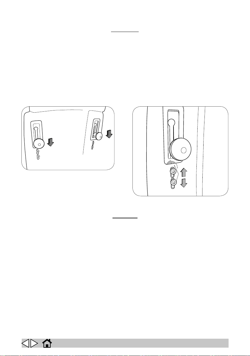
The side brushes direct dirt and debris towards the centre of the machine. The most ecient height
Never operate the machine without the side brushes installed.
for this purpose is when the side brushes gently touch the oor. Proceed as follows to increase or
reduce the pressure of the side brushes on the oor, if necessary.
► Lower the side brushes into work position (g. 21).
► Loosen the two locking screws under the brush lifting knob (g. 22).
► Manually move the brush to the required position.
► Tighten the locking screws again (g. 22).
► Return the brushes to idle position.
! WARNING!
21 22
Replacing/installing the suction lter
This operation must be performed with the machine switched o and the key removed.
The suction lter makes a major contribution to the eciency of the whole machine.
Its correct maintenance keeps the machine at maximum eciency at all times. If the sweeper begins
to raise dust as it sweeps, check the condition of the suction lter.
The suction lter can be cleaned in two ways.
Semiautomatic lter cleaning:
► This method provides a quick and easy way to keep the suction lter clean and ready for
work. Press and hold the lter shaker button for a number of seconds, then repeat four or
ve times. On Petrol and Diesel versions, shut o suction with the suction control lever
before pressing the lter shaker button.
! DANGER!
GB
31
Page 32
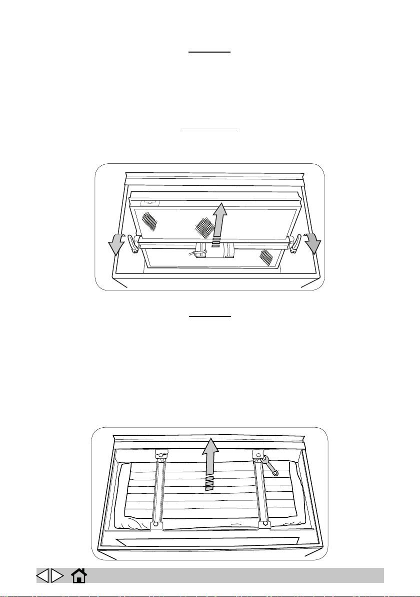
Manual cleaning of the panel lter:
FLOW
! DANGER!
This operation must be performed with the machine switched o and the key removed.
If the action of the lter shaker proves insucient, proceed as follows to clean the lter manually.
► Remove the lter compartment cover.
► Lift the two levers and remove the lter shaker bracket complete with the lter shaker mo-
tor, carefully disconnecting the power cable from the lter shaker (g. 23).
► Remove the suction lter (g. 23).
► Blow the lter clean with compressed air (maximum pressure 6 bar).
! IMPORTANT!
The lter is marked to show the correct direction for tting.
23
Manual cleaning of the pocket lter:
! DANGER!
This operation must be performed with the machine switched o and the key removed.
If the action of the lter shaker proves insucient, proceed as follows to clean the lter manually.
► Remove the lter compartment cover.
► Unscrew the four screws securing the two lter holder brackets (g. 24).
► Remove the two brackets (g. 24).
► Remove the lter, carefully disconnecting the power cable from the lter shaker (g. 24).
► Blow the lter clean with compressed air (maximum pressure 6 bar).
24
GB
32
Page 33
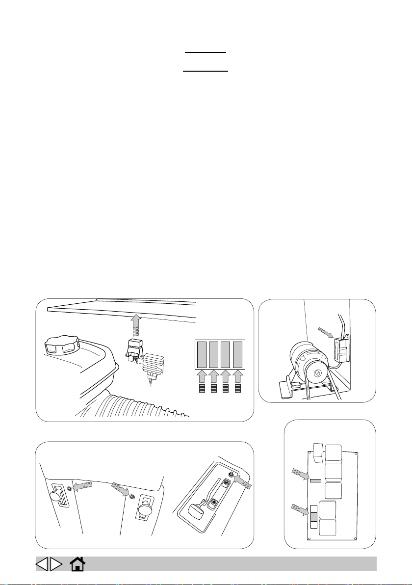
Fuses: replacing
Petrol - Diesel
21 3 4
Battery - Dual Power
Battery - Dual Power
1
2
This operation must be performed with the machine switched o and the key removed.
Never use a fuse with a higher amperage than specied.
If a fuse continues to blow, the fault in the wiring, boards (if present) or motors must be identied
and repaired: have the machine checked by qualied personnel.
DIESEL version:
(Fig. 25-Ref. 1) front light fuse (optional)
(Fig. 25-Ref. 2) blinker, buzzer, hour counter, horn and lter shaker relay coil fuse.
(Fig. 25-Ref. 3) starter motor fuse.
(Fig. 25-Ref. 4) lter shaker motor fuse.
PETROL version:
(Fig. 25-Ref. 1) lter shaker motor fuse.
(Fig. 25-Ref. 2) starter motor fuse.
(Fig. 25-Ref. 3) blinker, buzzer, hour counter, horn, lter shaker relay coil and front light fuse (op-
tional)
(Fig. 25-Ref. 4) generator fuse.
(Fig. 26), main fuse.
(Fig. 27), resettable central and side brush motor fuse, Battery and Dual Power version.
(Fig. 28-Ref. 1), lter shaker and suction motor fuse, (Fig. 28-Ref. 2) centre brush fuse, BATTERY
and DUAL POWER version.
! DANGER!
! WARNING!
25 26
27
GB
28
33
Page 34
Battery maintenance and charging
DIESEL
PETROL
DUAL POWER
The batteries give o ammable fumes. Put out all res and hot embers before checking or
Do not check the batteries by sparking.
Perform the operations described below in a ventilated area.
To avoid permanent damage to the batteries, do not run them down completely.
Charging procedure
Connect the battery charger connector to the battery wiring connector.
In the case of gel or other sealed (AGM) batteries, use a charger specic for this type of
battery only. Use of unsuitable chargers may be dangerous! If in doubt, contact your dealer.
Charge the batteries as instructed in the battery charger manual. The batteries in Battery and
Dual Power models require regular charging.
Disconnect the connectors at the end of charging.
When the machine is not being used, disconnect the batteries from the machine’s electrical
system using the emergency button..
! DANGER!
topping up the batteries.
! WARNING!
! WARNING!
!WARNING!
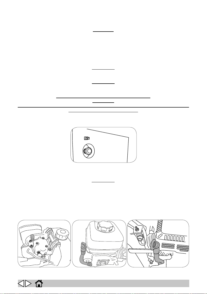
Changing the engine oil
On Dual power machines, change the engine oil when the “CHANGE ENGINE OIL” warning
appears on the display. On Petrol and Diesel machines, change the engine oil at the intervals
specied in the operation and maintenance manual provided by the engine manufacturer on
the basis of the hour counter on the machine’s dashboard. Always change engine oil with
31
the machine switched o and the engine cold.
32
! WARNING!
GB
33
34
Page 35
Check that all machine functions are disabled, then lift the top cowling. Check that the engine is not
hot enough to cause burns then proceed as follows.
► Once having identied the oil discharge hose connected to the engine, run it through the
hole on the engine compartment metal cover on the PETROL version; for the DIESEL and
DUAL POWER version, the side panel needs to be removed.
► Remove the oil level dipstick to facilitate drainage of the old oil.
► Position a suitable container under the drain pipe and unscrew the plug to let the old oil out.
► When the old oil has all drained out, t the plug back in the drain pipe and arrange the pipe
back inside the engine compartment, making sure that it does not interfere with any moving
parts.
► Pour oil into the engine through the dipstick tube (PETROL and DUAL POWER version,
Fig. 32, 33), observing the quantity specied in the engine’s manual; for the DIESEL en-
gine, pour the oil into the opening closed by the cap (Fig. 34) on the engine head, observ-
ing the quantity specied in the engine’s manual.
► Once the right quantity of new oil has been added, t the oil level dipstick and check that
the level is correct.
► Close the top cowling.
Top up hydraulic circuit oil on PETROL and DIESEL version
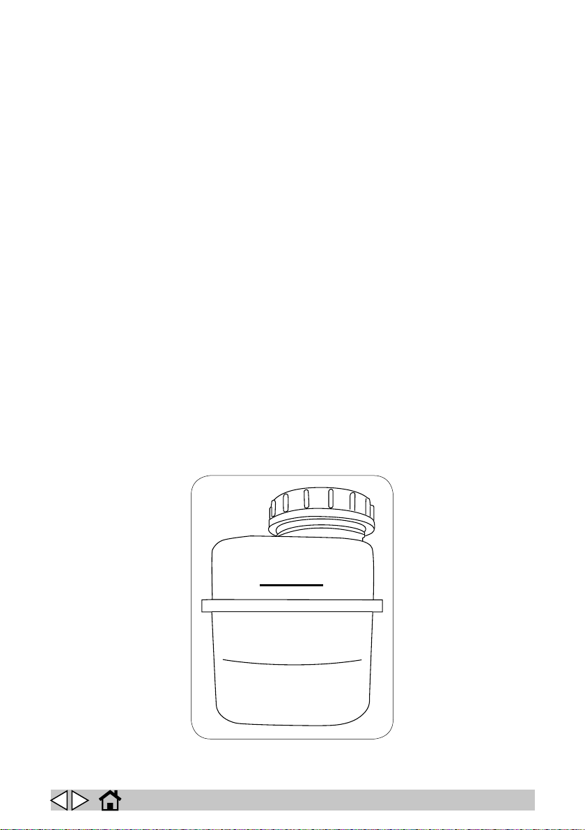
Check the oil level every 10 hours; if the level is below the minimum level indicator on the tank (Fig.
34), top up with “SAE 15 W40 Q8 T 700 I” oil.
34
OIL LEVEL
LIVELLO OLIO
GB
35
Page 36

Periodic checks
CHECK
ON DELIVERY
EVERY 10 HOURS
EVERY 50 HOURS
CHECK THE BATTERY ELECTROLYTE X X
CHECK THE HYDRAULIC OIL X X
CHECK THE CONDITION OF THE BELTS X
ADJUST THE BRAKE X
CHECK THE TIGHTNESS OF NUTS BOLTS X
CHECK THE CONDITION OF THE BRUSHES X
CHECK THE TIGHTNESS OF THE SEALS X
CHECK THE FUNCTIONING OF DEVICES X X
GREASE THE STEERING CHAIN X
EVERY 100 HOURS
GB
36
Page 37
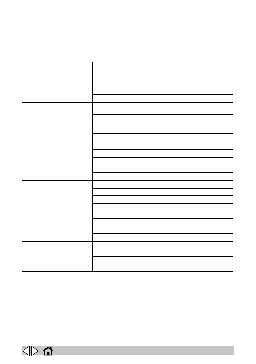
TROUBLESHOOTING
B= Battery
DP= Dual Power
P= Petrol
D= Diesel
PROBLEM CAUSE REMEDY
The machine raises dust. Filter clogged. (B,DP,P,D) Shake the lter with the lter shaker
Filter damaged. (B,DP,P,D) Replace the lter.
Filter incorrectly tted. (B,DP,P,D) Fit the lter correctly in its housing.
The machine leaves dirt on the ground. The main brush is not adjusted correctly
The main brush does not rotate. Belt broken. (B,DP,P,D) Replace.
The side brushes do not rotate. Belt broken. (P,D) Replace.
The suction motor does not work. Fuse burned out. (B,DP) Replace.
The lter shaker motor does not work. Fuse burned out. (B,DP,P,D) Replace.
or is worn. (B,DP,P,D)
The main brush has collected string or
wire. (B,DP,P,D)
The aps are damaged. (B,DP,P,D) Replace the aps.
Debris bin full. (B,DP,P,D) Empty the debris bin.
Fuse burned out. (B,DP) Replace.
Microswitch faulty. (B,DP) Replace.
Cable disconnected. (B,DP) Check.
Gearmotor faulty. (B,DP) Replace.
Cutout tripped. (B,DP) Reset.
Microswitch faulty. (B,DP) Replace.
Cable disconnected. (B,DP) Check.
Switch faulty. (B,DP) Replace.
Cable disconnected. (B,DP) Check.
Motor faulty. (B,DP) Replace.
Switch faulty. (B,DP,P,D) Replace.
Cable disconnected. (B,DP,P,D) Check.
Motor faulty. (B,DP,P,D) Replace.
and, if necessary, remove and clean it
thoroughly.
Adjust or replace the main brush as necessary.
Remove the string and wire picked up.
GB
37
Page 38
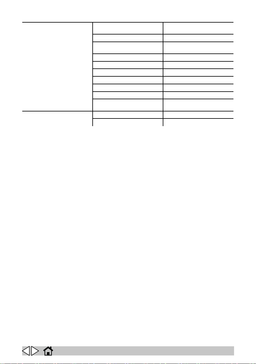
The machine won’t start. Battery terminals disconnected.
The batteries do not hold their charge. Electrolyte low. (B,DP,P,D) Top up.
(B,DP,P,D)
Batteries discharged. (B,DP,P,D) Recharge.
Emergency stop button pressed.
(B,DP,P,D)
No fuel. (DP,P,D) Top up.
No engine oil. (DP,P,D) Top up.
Driver detection device faulty. (B,DP,P,D) Replace.
Operator not correctly seated. Sit correctly in the seat.
Clutch not engaged. (P,D) Engage.
Main fuse burned out. (B,DP) Replace.
Power control board fuse burned out.
(B,DP)
Battery terminal loose. (B,DP,P,D) Tighten.
Check.
Reset.
Replace.
GB
38
Page 39

DISPLAY ALARMS
BRUSH MOTOR CUTOUT
TRIPPED
BRAKE The parking brake is engaged or the drive motor has over-
STAND-BY The driver detection microswitch is not detecting an operator.
RELEASE ACCELERATOR Incorrect starting sequence. Release the accelerator pedal
EEPROM 1 FAULT Replace the display board.
DRIVE CONTROL BOARD
CUTOUT TRIPPED
ACCELERATOR FAULT There is a problem with the accelerator cable.
MAX. SPEED POTENTIOM-
ETER FAULT
UNDERVOLTAGE FAULT Check the batteries.
The brush motor has overheated.
heated.
when starting.
The drive control board has overheated.
There is a fault in the maximum speed potentiometer cabling.
OVERVOLTAGE FAULT Check the batteries.
MAIN RELAY FAULT Replace the drive control board.
HPD Check the accelerator pedal. Switch the machine o and back
MOSFET FAULT Replace the drive control board.
EEPROM 2 FAULT Replace the drive control board.
on with the accelerator released.
GB
39
Page 40

SERVICE Call a service centre to arrange servicing.
BATTERY DISCHARGED Battery discharged.
START ENGINE Dual Power version only: start the engine to continue work.
BATTERY CHARGED Dual Power version only: batteries charged.
ALTERNATOR CUTOUT
TRIPPED
CHANGE ENGINE OIL Dual Power version only: change the engine oil.
COWLING OPEN
SWITCH OFF MOTOR/
ENGINE
Dual Power version only: the alternator has overheated.
GB
40
Page 41
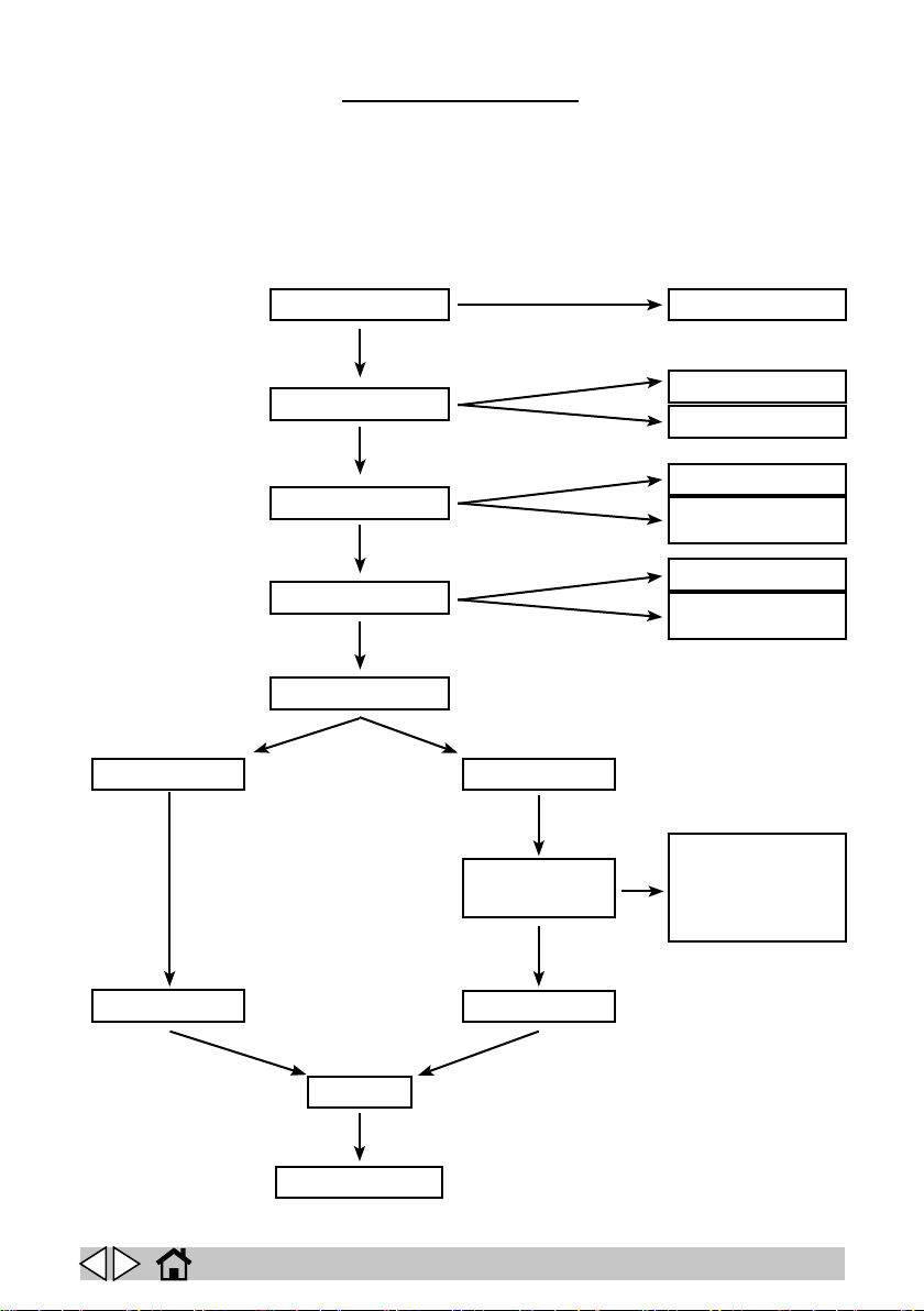
To access the technical menu, turn the main switch on then press and hold the menu and suction
TECHNICAL MENU
buttons for three seconds.
Press the “SUCTION” button to scroll up through items or increment the selected parameter value.
Press the “FILTER SHAKER” button to scroll down through items or decrement the selected pa-
rameter value.
Press the “MENU” button to select the parameter to change. The selected parameter appears in
negative.
LANGUAGE
BATTERY TYPE
AUTO POWER-OFF
FILTER SHAKER
MACHINE TYPE
BATTERY DUAL POWER
ALTERNATOR
TIME
IT, GB, ES....
ACID
GEL
OFF
TIME-OUT 0-10
SECONDS
MANUAL
AUTOMATIC 5-30
MINUTES
20-120 SECONDS
FROM ENGINE
STARTUP
EXIT
SAVE
GB
SERVICE MENUSERVICE MENU
41
Page 42
IP CLEANING S.p.A.
Sede Legale - Registered Oce
Viale Treviso n° 63 - fraz. Summaga
30026 Portogruaro (VE) ITALY
DICHIARAZIONE DI CONFORMITA’ “CE”
Dichiariamo sotto la nostra esclusiva responsabilità che il prodotto al
IT FI
quale questa dichiarazione si riferisce è conforme alle seguenti Direttive
Comunitarie:
“CE” CONFORMITY DECLARATION
We declare on our own responsibility that the product to which this
EN EL
declaration refers is in accordance with the following European
Community Directives :
DECLARATION DE CONFORMITE “CE”
Nous déclarons sous notre exclusive responsabilité que le produit
FR SK
auquel cette déclaration se réfère est conforme aux directives européen-
nes suivantes communautaire:
“CE” KONFORMITÄTSERKLÄRUNG
Auf unserer Alleinverantwortung erklären wir, daß das Produkt, auf das
DE HU
sich diese Erklärung bezieht entspricht den folgenden Richtlinien der
Europäischen Gemeinschaft :
DECLARACIÓN “CE” DE CONFORMIDAD
Bajo nuestra exlusiva responsabilidad, declaramos que el producto,
ES CS
al que esta declaraciòn se reere, es conforme con las siguientes
directivas comunitarias:
DECLARAÇÃO “CE” DE CONFORMIDADE
Declaramos sob a nossa exclusiva responsabilidade que o produto ao
PT ET
qual esta declaração se refere está em conformidade com as seguintes
directivas comunitárias:
DECLARAÇÃO “CE” DE CONFORMIDADE
Declaramos sob a nossa exclusiva responsabilidade que o produto ao
NL LT
qual esta declaração se refere está em conformidade com as seguintes
directivas comunitárias:
OVERENSSTEMMELSESERKLÆRING “CE”
Vi forsikrer under eget ansvar at folgende produkt som omfattes af
DA SL
denne erklæring er i overensstemmelse med vilkårene i folgende EU
direktiver:
FÖRSÄKRAN OM ÖVERENSSTÄMMELSE “CE”
Vi försäkrar under eget ansvar att följande produkt som omfatts av den-
SV PL
na försäkran i överensstämmelse med villkoren i följande Europeiska
gemenskapens direktiv:
BEKREFTELSE OM OVERENSSTEMMELSE “CE”
Vi forsikrer under eget ansvar at folgende produkt som omfattes av
N LV
denne bekreftelsen er i overensstemmelse med vilkärene i folgende
disse EU-direktivene:
YHDENMUKAISUUSVAKUUTUS “CE”
Vakuutamme omalla vastuulamme, että seuraava tuote jota tämä
vakuutus koskee, on yhdenmukainen seuraavassa Euroopan yhteisön
direktiivit :
Δηλώνουμε φέροντας την αποκλειστική ευθύνη ότι το προϊόν στο οποίο
αναφέρεται η δήλωση αυτή είναι σύμφωνη με τις ακόλουθες οδηγίες της
Ευρωπαϊκής Κοινότητας:
Prehlasujeme na vlastnú zodpovednosť, že výrobok, na ktorý sa
vzťahuje toto prehlásenie je zhodný s nasledujúcimi Európskeho
spoločenstva:
Saját felelősségünk alatt kijelentjük, hogy a termék, amelyre a nyilatkozat vonatkozik, megfelel az következő európai közösségi irányelvek:
Prohlašujeme výlučně na vlastní zodpovědnost, že výrobek, na který
se vztahuje toto prohlášení je ve shodě s následujícími Evropského
společenství:
Deklareerime meie ainuvastutuse juures, et see toode vastab järgmiste-
le standarditele ja Euroopa Ühenduse direktiivide:
Prisiimdami visą atsakomybę, mes pareiškiame, kad produktas, kuriam
taikoma ši deklaracija, atitinka šiuos Europos Bendrijos direktyvas:
Izjavljamo na našo odgovornost, da je izdelek, na katerega se nanaša ta
deklaracija, v skladu s sledečimi direktivami Evropske skupnosti :
Oświadczamy na naszą wyłączną odpowiedzialność, że produkt, którego dotyczy niniejsza karta gwarancyjna, jest zgodny z następującymi
dyrektywami Wspólnoty Europejskiej:
Prisiimdami visą atsakomybę, mes pareiškiame, kad produktas, kuriam
taikoma ši deklaracija, atitinka šiuos Eiropas Kopienas direktīvas:
D»lwsh snmbatÒthtaj “CE”
PREHLÁSENIE “EÚ” O ZHODNOSTI
“CE” MEGFELELŐSÉGI NYILATKOZAT
PROHLÁŠENÍ “CE” O SHODĚ
“CE” VASTAVUSDEKLARATSIOON
“CE” ATITIKTIES DEKLARACIJA
IZJAVA O SKLADNOSTI “CE”
DEKLARACJA ZGODNOŚCI “UE”
“CE” ATITIKTIES DEKLARACIJA
2006/42/CE - 2014/30/CE - 2005/88/CE - 2011/65/EU - 2014/35/CE
Norme armonizzate applicate - Applied harmonised standards: Altri standards applicati - Others applied standards:
Prodotto-Product:
MOTOSPAZZATRICE - FLOOR SWEEPER
Modello-Model-Modèle-Modell-Modelo-Modell-Malli-MonteloMudel-Modelis:
Matricola-Serial n.-Matricule-Maschinennummer-Matricula-Serienummer-Sarjanumero-Registratienummer -(Ariqmos) MhtrwonVýrobné číslo-Sorozatszám-Výrobní číslo-Seeria nr-Serijos
Nr.-Serijska številka-Nr seryjny-Serijos Nr.:
Persona autorizzata a costituire il Fascicolo Tecnico.
Person authorised to compile the Technical File.
IP CLEANING S.p.A.
Viale Treviso n° 63 - fraz. Summaga
30026 Portogruaro (VE) ITALY
Serial n°
Incollare la matricola sulla garanzia.
Coller la matricule sur la carte garantie.
Pegar la matricula en la garantia.
Registtratie-nummer op de garantie plakken.
Klistr serienummeret på garantiseddelen.
Liimaa sarjanumero takuutodistukseen.
Stik the serial number on the warranty card .
Maschinenummer auf den Garantieschein Kleben.
Cole o número de matrícula na garantia.
Klistr serienummeret pà garantiseddelen.
Kollƒste ton ariqmÒ mhtrèon sthnsh eggÚhs
Výrobné číslo nalepte na záručný list.
A sorozatszámot ragassza a garancialevélre.
Nalepit výrobní číslo na záruku.
Seerianumber tuleb kinnitada garantiikaardile.
Garantiniame pase turi būti nurodytas serijos
numeris.
Serijska številka mora biti nalepljena na garanciji.
Należy nakleić numer seryjny na kartę
gwarancyjną.
POSITION: General Manager Date: 27/08/15
NAME: Federico De Angelis Signature:
Testato - Checked - Essayé - Geprüft - Testado - Provekort - Koeajettu - Getest -
Leverans -Dokimasmeno - Vyskúšané - Bevizsgált - Testováno - Kontrollitud - Patikrinta
- Preizkušeno -Sprawdzono - Patikrinta
Il collaudatore:
Serial n°
Page 43

IP Cleaning S.p.A.
Viale Treviso 63
30026 Summaga di Portogruaro
Venezia (Italy)
T: +39 0421 205511
F: +39 0421 204227
E: www.ipcworldwide.com
W: [email protected]
PLDC02107_10
 Loading...