


nanoLTE E61 AP Hardware Installation
NANO_INST_43325 205_0.6

Notices
This document is provided to you by or on behalf of ip.access Ltd ("ip.access").
© ip.access Limited 2019.
The documentation and any software described herein and/or provided to you in conjunction with this
documentation contain proprietary and confidential information of ip.access and may only be used
subject to a license agreement containing restrictions on use and disclosure. They are also protected
by copyright, patent rights and other intellectual and industrial property laws. The information
contained in this document and any software described herein is subject to change without notice. If
you find any problems in the documentation and/or the software please report them to us in writing.
The document and/or the software are not warranted to be error-free. No right, title, license or interest
in any physically or electronically distributed materials is transferred to you by such distribution. No
part of this document and/or the software may be reproduced, displayed, copied, translated, adapted,
downloaded, electronically transmitted, used or reproduced in any form including (without limitation)
distribution or storage in a system for retrieval without our express written permission (which may be
subject to conditions).
The documentation and/or software may provide links to Web sites and access to content, products,
and services from third parties. ip.access is not responsible for the availability of, or any content
provided on, third-party Web sites. You bear all risks associated with the use of such content. If you
choose to purchase any products or services from a third party, the relationship is directly between you
and the third party. ip.access is not responsible for: (a) the quality of third-party products or services; or
(b) fulfilling any of the terms of the agreement with the third party, including delivery of products or
services and warranty obligations related to purchased products or services. ip.access is not
responsible for any loss or damage of any sort that you may incur from dealing with any third party.
ip.access is the owner of the "ip.access" trademark and all associated trade names, logos and devices
unless indicated to the contrary. Any other trademarks, logos and names appearing in this document
may be the property of their respective owners.
ip.access Limited is a Private Limited Company Registered in England and Wales
Company No. 03400157
Registered Office:
Building 2020
Cambourne Business Park
Cambourne
CB23 6DW
UK
Tel: +44 (0) 1954 713 700
Fax: +44 (0) 1954 713 799
Further company information may be found at www.ipaccess.com.

Revision History
Version Change Summary Date Author
205_0.1 First draft 12 Mar 2019 AM4
205_0.2 Update regulatory information from review feedback 14 Mar 2019 AM4
205_0.3 Update electrical safety information from review feedback 18 Mar 2019 AM4
205_0.4 Corrections from review feedback 19 Mar 2019 AM4
205_0.5 Add PSU option 22 Mar 2019 AM4
205_0.6 Minor correction 01 Apr 2019 AM4

Table of Contents
1 Introduction............................................................................................1
1.1 Overview ............................................................................................................ 1
1.2 Warnings and Regulatory Information ............................................................... 1
1.3 Related Information............................................................................................ 1
1.4 Licenses and Copyright Notices ........................................................................ 1
1.5 Terminology ....................................................................................................... 1
2 Installation Overview and Requirements ............................................ 2
2.1 Installation Tasks ............................................................................................... 2
2.1.1 Pre-Provisioning ................................................................................................... 2
2.1.2 Commissioning..................................................................................................... 2
2.1.3 Site Installation ..................................................................................................... 2
2.2 Mounting Options............................................................................................... 3
2.3 nanoLTE E61 AP Site Requirements................................................................. 3
2.3.1 General Site Installation Requirements................................................................ 3
2.3.2 AP Cooling ........................................................................................................... 4
2.3.3 Port Usage ........................................................................................................... 4
2.3.4 nanoLTE E61 AP Power Requirements ............................................................... 7
2.3.5 E61 AP Physical Requirements ........................................................................... 9
2.3.6 Thermal Protection ............................................................................................. 10
2.3.7 Backhaul (IP) Bandwidth Requirements............................................................. 10
2.3.8 E61 AP Installation Tool Requirements for Wall Mounting................................. 10
3 nanoLTE E61 AP Commissioning ......................................................11
3.1 Requirements for Commissioning with the Web Page..................................... 12
3.1.1 Information Required for Commissioning ........................................................... 12
3.1.2 Other Items for Commissioning.......................................................................... 13
3.2 Redirector First Contact and NTP Synchronisation for Software Update ........ 14
3.3 Configure a Commissioning Terminal.............................................................. 15
3.4 Access the Commissioning Web Page for the LTE AP ................................... 16
3.5 Optional - Software Download ......................................................................... 17
3.6 Configure the Connection to the NOS Server.................................................. 19
3.6.1 Static IP Configuration........................................................................................ 19
3.6.2 Configure IPsec.................................................................................................. 19
3.6.3 Configure the TR-069 Management Connection................................................ 20
3.6.4 Complete the LTE AP Commissioning ............................................................... 20
3.7 Commissioning Complete ................................................................................ 21
3.7.1 Completed On Site Commissioning ................................................................... 21
3.7.2 Completed Commissioning in Advance.............................................................. 21
4 nanoLTE E61 AP Hardware Installation............................................22
4.1 Unpack the E61 AP.......................................................................................... 22
4.2 Cable Connections........................................................................................... 23
nanoLTE E61 AP Hardware Installation
NANO_INST_43325 v205_0.6 for N4G_2.5 © ip.access Limited 2019 Page i

4.2.1 PSU and LAN ..................................................................................................... 23
4.2.2 Optional PoE+ Injectors ..................................................................................... 24
4.2.3 PoE+ Switch ....................................................................................................... 24
4.2.4 GPS Source ....................................................................................................... 24
4.3 Mount the E61 AP on a Wall or Ceiling............................................................ 25
5 Troubleshooting ..................................................................................27
5.1 E61 AP Does Not Power Up............................................................................ 27
5.2 E61 AP LEDs ................................................................................................... 27
5.3 Factory Reset................................................................................................... 30
5.3.1 E61 AP Factory Reset........................................................................................ 30
6 AP and PSU Regulatory Information ................................................. 31
6.1 Warnings and Cautions - nanoLTE E61 AP..................................................... 31
6.2 Warnings and Cautions - Optional Power Supply Unit .................................... 33
6.3 Regulatory Statements for the E61 AP............................................................ 34
6.3.1 US FCC Compliance .......................................................................................... 34
6.3.2 Safety Standards................................................................................................ 34
6.3.3 Environmental Standards ................................................................................... 34
6.3.4 RF Exposure Statement ..................................................................................... 35
6.4 Regulatory Statements for PSU....................................................................... 36
6.4.1 Output Specification ........................................................................................... 37
nanoLTE E61 AP Hardware Installation
NANO_INST_43325 v205_0.6 for N4G_2.5 © ip.access Limited 2019 Page ii

1 Introduction
The nanoLTE E61 AP from ip.access is a compact Small Cell that provides LTE TDD
capability. The E61 AP is targeted at indoor enterprise applications.
This manual provides important information on installing the E61 AP hardware.
1.1 Overview
This manual is organised as follows:
• This introduction
• An overview of E61 AP installation, including site requirements
• E61 AP hardware installation
• Troubleshooting
• Regulatory warnings and safety information
1.2 Warnings and Regulatory Information
For all warnings and regulatory information, see section 6.
1.3 Related Information
[INST_13400] AP Pre-Provisioning and Configuration (NANO_INST_13400)
[REF_11105] System Glossary (NANO_REF_11105)
[REF_43005] nanoLTE AP Open Source Software (NANO_REF_43005)
[TRB_13005] AP Troubleshooting (NANO_TRB_13005)
[21.905] Vocabulary for 3GPP Specifications (3GPP TR 21.905)
1.4 Licenses and Copyright Notices
Portions of the AP software are constructed from third-party software and open source code
and ip.access Ltd gratefully acknowledges the contributions that these libraries,
technologies and components have made to the product. Each of these is supplied under
the terms of a license agreement and these are either reproduced or referenced in
[REF_43005], in line with the stipulations of their authors.
1.5 Terminology
Common System terminology is defined in [REF_11105].
For additional terminology, see [21.905].
nanoLTE E61 AP Hardware Installation Introduction
NANO_INST_43325 v205_0.6 for N4G_2.5 © ip.access Limited 2019 Page 1

2 Installation Overview and Requirements
The topics in this section are:
• 2.1 Installation Tasks
• 2.2 Mounting Options
• 2.3 nanoLTE E61 AP Site Requirements
2.1 Installation Tasks
The tasks that must be completed to install a nanoLTE E61 AP and make it ready to provide
service are:
• Pre-Provisioning in the NOS
• Commissioning
• Site installation
These tasks can be completed in any order. In most cases, however, the most practical
approach is to pre-provision an E61 AP before commissioning and site installation.
2.1.1 Pre-Provisioning
The pre-provisioning process prepares an AP to enter service.
For information about AP pre-provisioning, see the AP Pre-Provisioning and Configuration
manual [INST_13400]. The LTE AP runs LTE AP2.5 software.
This manual has no further information on AP configuration.
2.1.2 Commissioning
The commissioning procedure prepares the E61 AP so that it is ready to connect to its
serving NOS, usually via a serving IPsec GW.
The commissioning procedure is in section 3.
2.1.3 Site Installation
Physical installation of an E61 AP at its operating site, including providing the AP with
power and a suitable network connection. The network connection provides the backhaul
path to the NOS Server and LTE Gateway, usually via an IPsec GW.
The network connection must also provide Internet access so that the E61 AP can contact
the services it needs at boot time, including NTP, the Redirector and the public CRL mirror.
If an E61 AP has been enabled for service prior to the site visit, the installation engineer can
make test calls immediately.
nanoLTE E61 AP Hardware Installation Installation Overview and Requirements
NANO_INST_43325 v205_0.6 for N4G_2.5 © ip.access Limited 2019 Page 2

2.2 Mounting Options
The E61 is designed for wall or ceiling mounting on the supplied mounting bracket.
The hardware installation procedure in section 4 is applicable to both options.
2.3 nanoLTE E61 AP Site Requirements
The basic requirements are:
• A mounting location for the E61 AP.
• Power supplied via the supplied mains adaptor unit, which requires a suitable
mains power supply point near the AP that is within reach of the adaptor’s cabling,
or via PoE+ to each Ethernet socket.
• An Ethernet cable connections to the Internet, or equivalent backhaul network.
Optionally also provide:
• A GPS source for frequency discipline.
2.3.1 General Site Installation Requirements
The more general requirements for installation are:
• A permanent means to provide power to the AP
• An Ethernet connection to the backhaul via CAT5 Ethernet cabling
• Access to a DHCP service on the backhaul to allow dynamic IP address
configuration
• Access to a DNS service on the backhaul to resolve symbolic addresses
• Access to NTP services on the backhaul to set the correct time and date each time
the AP starts up
• Internet access so that the LTE AP can connect to the Redirector
• If IPsec will be used to secure the interface across the backhaul, access to the
relevant IPsec Gateway that terminates the IPsec tunnel
• If a firewall is in place on the network an AP will use for backhaul, this must be
configured to allow traffic to and from the AP - see the port usage information in
section 2.3.3
Note: If possible, the engineer should stay on site until the AP is brought into service, ready to
make test calls to verify the AP has been configured correctly from the NOS.
nanoLTE E61 AP Hardware Installation Installation Overview and Requirements
NANO_INST_43325 v205_0.6 for N4G_2.5 © ip.access Limited 2019 Page 3

2.3.2 AP Cooling
Special attention must be given to ensure a AP will meet its air cooling requirements in its
installed location.
Take the following points into consideration for the physical location of an AP:
• The AP must be installed where there will be proper air will flow through the body
of the AP to provide cooling.
• The AP MUST NOT be installed in an enclosed space where air flow is restricted.
This includes, but is not necessarily limited to:
• Roof or ceiling spaces
• Small cabinets
• Tightly enclosed shelf spaces
2.3.3 Port Usage
This information is provided in case it is needed for configuring local on-premises
equipment, especially any hardware firewalls between the AP and the rest of the backhaul
network.
All connections are outgoing. That is, they are initiated from the AP. Port usage has some
dependency on whether or not the AP is using IPsec.
Port Usage Before IPsec
The AP can use any of the following ports before the IPsec tunnel is established:
Protocol Destination Port Use
udp 67 DHCP
udp 68 DHCP
udp 53 DNS
udp 123 NTP
tcp 443 HTTPS for connecting to the Redirector (LTE only)
tcp 80 HTTP for first CRL download for a new AP or after
Factory Reset
The AP may continue to use some of these ports outside the IPsec tunnel. For example, for
contacting NTP servers.
nanoLTE E61 AP Hardware Installation Installation Overview and Requirements
NANO_INST_43325 v205_0.6 for N4G_2.5 © ip.access Limited 2019 Page 4

AP in Commissioning Mode
When the AP is in commissioning mode after a factory reset, this is the only time that the
AP allows an inbound connection. The LTE AP takes the fixed IP address 192.168.0.10.
The AP then listens for an incoming connection to the commissioning web page:
Protocol Destination Port Use
tcp 8089 Commissioning web page
Note: The commissioning web page is only available if the LTE AP’s DOCP (obtained from the
Redirector) indicates that the LTE AP should enable the web page.
Port Usage With IPsec
With IPsec, the standard two ports are used:
Protocol Destination Port Use
udp 500 IPSec initial connection
udp 4500 IPSec operations
The AP will need to continue using these ports:
Protocol Destination Port Use
udp 53 DNS
udp 123 NTP
If the NOS is configured for HTTPS access to the Certificate Validation Service for CRL
Mirror server functionality, the AP will also need to use this port outside of the IPsec tunnel:
Protocol Destination Port Use
tcp 443 HTTPS for CRL download from the NOS
nanoLTE E61 AP Hardware Installation Installation Overview and Requirements
NANO_INST_43325 v205_0.6 for N4G_2.5 © ip.access Limited 2019 Page 5

Port Usage Without IPsec
Without IPsec, the following ports are used:
Protocol Destination Port Use
sctp 36412 SCTP connection
udp 2152 GTP to/from AP
tcp 8080 or 7547 TR-069 to the NOS (the NOS listens for TR-069
connections on both ports)
tcp 80 PM upload, software download, CRL download, AP
diag upload
This assumes the AP is on a secure network that does not need IPsec. For example, a
self-contained test network.
nanoLTE E61 AP Hardware Installation Installation Overview and Requirements
NANO_INST_43325 v205_0.6 for N4G_2.5 © ip.access Limited 2019 Page 6

2.3.4 nanoLTE E61 AP Power Requirements
Maximum expected power consumption:
• Approx 16W (Rated +12V on the DC input)
The E61 AP uses power from a suitable DC source (+12V, 1.8A rated centre positive
2.1mm jack). Use the supplied mains adaptor only.
Alternatively, provide PoE+ via the Ethernet connection. The mains power adaptor is not
required in this case.
PSU
The following 12V PSU, rated up to 30W, is included in the box with the E61 AP:
There must be a suitable mains power supply point for plugging in the power adapter. The
lead on the PSU is 1.5m long, hence the power supply point must be within 1.5m of the AP.
Note: This PSU has a maximum ambient operating temperature rating of 40°C. An alternative
PSU, part number PSAA30R-050(MOT), is available for deployments where the ambient
temperature is above 40°C. If there is a requirement to obtain the alternative PSU, contact
an ip.access representative.
nanoLTE E61 AP Hardware Installation Installation Overview and Requirements
NANO_INST_43325 v205_0.6 for N4G_2.5 © ip.access Limited 2019 Page 7

Optional PoE+ Injector
If required, this must be ordered separately.
The PoE+ injector has two Ethernet connections, one for connection to the main LAN, the
other for connection to the AP. The PoE+ injector can be located anywhere on the cable run
between the network switch and the AP, including locally at the AP or remotely at the
network switch.
The PoE+ injector is a pass-through connector for the LAN. Its function is to add PoE+ to
provide power to the AP. Therefore, the maximum cable run from the network switch to the
AP is 100m, regardless of the placement of the PoE+ injector.
The PoE+ injector supplied by ip.access complies with LPS requirements in accordance
with IEC/EN 60950-1.
nanoLTE E61 AP Hardware Installation Installation Overview and Requirements
NANO_INST_43325 v205_0.6 for N4G_2.5 © ip.access Limited 2019 Page 8

2.3.5 E61 AP Physical Requirements
An E61 AP is installed by attaching its mounting bracket to a wall or ceiling, then fitting the
AP onto the mounting bracket.
Pay attention to ensure that air can circulate freely around the unit.
It is recommended to install the AP with its front surface facing the area requiring cellular
coverage, unobstructed by walls or partitions that may cause significant RF attenuation.
Dimensions and weight with
moutning bracket
Environmental Cooling Vents on all sides must be kept clear
Height 220mm
Width 290mm
Depth 67.1mm
Approximate Weight 1.6kg
of obstructions
Operating Temperature 0°C to +45°C - wall mounted
0°C to +35°C - ceiling mounted
Operating Humidity 10 to 70% non-condensing
nanoLTE E61 AP Hardware Installation Installation Overview and Requirements
NANO_INST_43325 v205_0.6 for N4G_2.5 © ip.access Limited 2019 Page 9

2.3.6 Thermal Protection
The E61 AP may become warm during normal operation.
Ensure the AP is in a location where it will be at least 20cm away from personnel and any
items that may be heat sensitive.
2.3.7 Backhaul (IP) Bandwidth Requirements
At maximum capacity and with IPsec in use, the E61 AP requires:
• Downlink: 110Mbps
• Uplink: 10Mbps
This will provide bandwidth for 32 users.
2.3.8 E61 AP Installation Tool Requirements for Wall Mounting
To mount the bracket onto the wall:
• 4 pan head screws, size No. 6 (approx 3.5mm (0.14in) in diameter), for the AP
bracket.
• Wall plugs if required.
• Suitable drills and screwdriver.
Note: A set of 4 standard screws and 4 standard wall plugs are included with the E61 AP. The
screws and wall plugs are suitable for solid walls. It may be necessary to source alternative
fixings if they are not suitable for the type of wall material on site.
nanoLTE E61 AP Hardware Installation Installation Overview and Requirements
NANO_INST_43325 v205_0.6 for N4G_2.5 © ip.access Limited 2019 Page 10

3 nanoLTE E61 AP Commissioning
Use the procedures in this section to configure the E61 AP with the settings it needs to
establish a connection with its serving NOS Server. Once commissioning is complete, use
the NOS Client for any remaining configuration and to bring the AP into service.
There are two LTE AP commissioning methods:
• Redirector Only Commissioning
The Redirector supplies the NOS connection parameters in the DOCP. In this
case, all the LTE AP requires is a connection to the Internet so that it can connect
to the Redirector. No other commissioning activities are possible. This is the
easiest way to commission an nanoLTE E61 AP. In this case, proceed to the
hardware installation procedure in section 4.
or
• Redirector Enables the Commissioning Web Page
The Redirector supplies the AP with a DOCP that enables the built-in
commissioning web page. The AP is not provided with any of the parameters that it
needs to connect to its serving NOS (or equivalent TR-069 ACS). The parameters
must be provided via the built-in commissioning web page. In this case, follow the
procedures in the rest of this section.
The rest of this section is only applicable to commissioning with the built-in web page. If this
is not enabled, proceed to the hardware installation procedure in section 4.
When using the commissioning web page, the nanoLTE E61 AP can be commissioned
either in advance of the site visit via a commissioning computer or on site via a
commissioning laptop. The web page based procedure is identical in both cases. To allow
for both of these scenarios, the term commissioning terminal is used to refer to any laptop
or computer used for commissioning.
The topics in this section are:
• 3.1 Requirements for Commissioning with the Web Page
• 3.2 Redirector First Contact and NTP Synchronisation for Software Update
• 3.3 Configure a Commissioning Terminal
• 3.4 Access the Commissioning Web Page for the LTE AP
• 3.5 Optional - Software Download
• 3.6 Configure the Connection to the NOS Server
• 3.7 Commissioning Complete
nanoLTE E61 AP Hardware Installation nanoLTE E61 AP Commissioning
NANO_INST_43325 v205_0.6 for N4G_2.5 © ip.access Limited 2019 Page 11

3.1 Requirements for Commissioning with the Web Page
The following items are required for commissioning:
• A commissioning terminal, which can be either a desktop computer or a laptop,
with:
• OS: Windows® 7 or later
• Web browser: Microsoft Internet Explorer 7 or later
• JavaScript enabled in the web browser
• A spare connection to allow the AP to connect to the Internet - this is so that the AP
can connect to the Redirector briefly after a Factory Reset before switching the AP
over to the commissioning terminal
• A short Ethernet cable for connecting the commissioning terminal to the LTE AP
• A temporary means to provide power to the AP while it is connected to the
commissioning terminal - typically use the supplied power adaptor
• Optionally, if a software update is required, a copy of the required LTE AP software
file on the commissioning terminal - this should only be used if the LTE AP will not
be managed by the NOS, as there are additional requirements that must be met
when downloading software from an attached commissioning terminal
3.1.1 Information Required for Commissioning
Use this information to commission an LTE AP from the commissioning terminal, so that the
LTE AP can subsequently connect to its serving NOS Server.
It is possible to commission an AP before taking it on site.
For connecting to the LTE AP from the commissioning terminal:
• User name and password for the LTE AP’s web server - if necessary, contact
customer support at ip.access for the current user name and password
For commissioning the LTE AP:
• IP Address or FQDN of the serving NOS Server
• IP Address or FQDN of an NTP server
• DHCP or static IP
• If static IP is required:
• IP address for the LTE AP
•Netmask
• IP Address or FQDN of the default gateway
• IP Address or FQDN of the Primary DNS
• IPSec configuration (usually required, but see note below):
• IP Address or FQDN of the IPsec Gateway
• IP Address or FQDN of a CRL server
nanoLTE E61 AP Hardware Installation nanoLTE E61 AP Commissioning
NANO_INST_43325 v205_0.6 for N4G_2.5 © ip.access Limited 2019 Page 12

• Optionally, Traffic Selector information (IP address and subnet mask)
A traffic selector defines a range of IP addresses that are sent through the
IPSec tunnel. This allows an extra degree of control over the traffic that is
passed down the IPSec tunnel. Normally, the IPsec Gateway controls this
range and no other configuration is needed.
• NTP server address
This is the address of an NTP server from which the LTE AP can obtain its clock
time on startup. The correct clock time is required for security certificate validation.
Hence, the LTE AP must be able to access this NTP server before establishing an
IPsec tunnel and/or connecting to its serving NOS. Although APs have an
ip.access NTP server configured by default, operators are recommended to
configure APs with the address of their own first-contact NTP server.
Note: IPsec configuration is required in all cases where an AP will traverse any public or insecure
network. This is assumed to be the case in most deployments. IPsec is not necessary only
when an LTE AP can establish an end-to-end connection to the NOS and its nanoLTE GW
and/or EPC via fully secure trusted networks.
3.1.2 Other Items for Commissioning
The items in this section can only be used if the commissioning terminal is running a web
server that provides a path to any ip.access AP software download packages. That is, the
required .sdp files must be present on the commissioning terminal.
Setting up a web server for this purpose on the commissioning terminal is outside the scope
of this manual.
Software Image
If there is a requirement to update the LTE AP’s software during commissioning, the
relevant *_signed.sdp file must be present on the commissioning terminal.
In addition, the LTE AP must be able to update its clock time with NTP prior to downloading
the software. This is to ensure the LTE AP does not reject the software due to having a
clock time set that is in the past compared to the time/date stamp in the LTE AP software
load.
nanoLTE E61 AP Hardware Installation nanoLTE E61 AP Commissioning
NANO_INST_43325 v205_0.6 for N4G_2.5 © ip.access Limited 2019 Page 13

3.2 Redirector First Contact and NTP Synchronisation for Software Update
The LTE AP must be connected to the Internet at least once so that it can obtain its unique
OLM Package from the Redirector. If the LTE AP has not yet downloaded its OLM package,
it will not be possible to use the commissioning web page.
NTP synchronisation is necessary when there is also a requirement to update the LTE
software using the commissioning web page. This applies regardless of the current
software load on the LTE AP.
Note: This is not necessary when using the NOS to update the LTE AP’s software, as the LTE AP
has to use NTP to update its clock time before it connects to the NOS. For more information
about when the LTE AP uses NTP in its startup sequence, see [TRB_13005].
The LTE AP software is always code signed. The LTE AP must have an up to date clock
time so that it can verify that the time stamp in the signed software is valid. The LTE AP has
a "last known time" that it updates hourly, and the last known time is also preserved across
a reboot or factory reset. If the last known time is in the past in comparison to the time
stamp in the LTE AP software package, the AP will reject the software load.
Hence, when using the LTE AP’s commissioning web page to update the software, it is
recommended to ensure the LTE AP uses NTP to obtain the current time, so that the last
known time is up to date before starting the commissioning web page. To do this:
1) Connect the LTE AP to the Internet and reboot it. The LTE AP will automatically
update its clock time with NTP.
If the LTE AP has not yet contacted the Redirector, it will also connect to the
Redirector and obtain its unique OLM package. This enables the built-in
commissioning web page the next time that a Factory Reset is performed on the
LTE AP.
2) If updating the software from the commissioning web page, also leave the AP
switched on for at least an hour to ensure it updates its "last known time".
The AP is now ready for commissioning and will accept code signed software
downloads via the commissioning web page.
nanoLTE E61 AP Hardware Installation nanoLTE E61 AP Commissioning
NANO_INST_43325 v205_0.6 for N4G_2.5 © ip.access Limited 2019 Page 14

3.3 Configure a Commissioning Terminal
Use this procedure to configure a Windows® computer used as a commissioning terminal
so that it has an IP address in the same address space as the LTE AP.
1) Open the Windows Control Panel on the commissioning terminal.
2) Go to Network Connections.
3) Right-click the relevant Local Area Connection and select Properties.
4) In the list of items on the General tab, select Internet Protocol (TCP/IP) and then
click Properties. A dialogue similar to the following appears (this varies according
to the version of Windows):
5) If it is not possible to leave this network connection permanently configured for AP
commissioning, make a note of the current settings.
6) Click the Use the following IP address radio button.
7) Set the IP Address to 192.168.0.2.
8) Set the Subnet Mask to 255.255.255.0.
9) There is no default gateway, so ensure the default gateway address is cleared.
10) Click OK to close and save the changes in each of the two dialogues. Also close
the Control Panel.
nanoLTE E61 AP Hardware Installation nanoLTE E61 AP Commissioning
NANO_INST_43325 v205_0.6 for N4G_2.5 © ip.access Limited 2019 Page 15

3.4 Access the Commissioning Web Page for the LTE AP
The commissioning web page is only accessible after performing a factory reset. The login
prompt for this web page is available for 10 minutes, after which the LTE AP will attempt to
boot normally.
1) Plug an Ethernet cable into the AP that is connected to a network that allows the
AP to connect to the Internet.
2) Plug in the power supply unit that is in the box with the AP to a mains outlet and
the AP. The AP will start up.
3) Perform a factory reset on the LTE AP:
• Press and hold the LTE AP reset button for at least 5 seconds, then release
the reset button.
• The LTE power LED will briefly turn red as the AP reboots, and will then
return to green.
Note: See section 5.3 for more information about factory reset.
4) Make a note of the time that the factory reset was started. The login prompt for the
web commissioning page will start to be available after the AP has contacted the
Redirector and re-downloaded its OLM Package. From this point, the login prompt
will be available for 10 minutes.
5) During this interval, start a web browser on the commissioning terminal.
6) After 10 minutes from starting the factory reset, swap the AP to the Ethernet cable
that connects it directly to the commissioning terminal.
7) In the address bar of the web browser on the commissioning terminal, type in the
pre-defined static IP address and port number for the web server on the AP and
press <Enter>:
http://192.168.0.10:8089
8) A login screen should appear in the browser. If the login screen does not appear
immediately, refresh the browser screen once every 20 seconds until it appears.
nanoLTE E61 AP Hardware Installation nanoLTE E61 AP Commissioning
NANO_INST_43325 v205_0.6 for N4G_2.5 © ip.access Limited 2019 Page 16
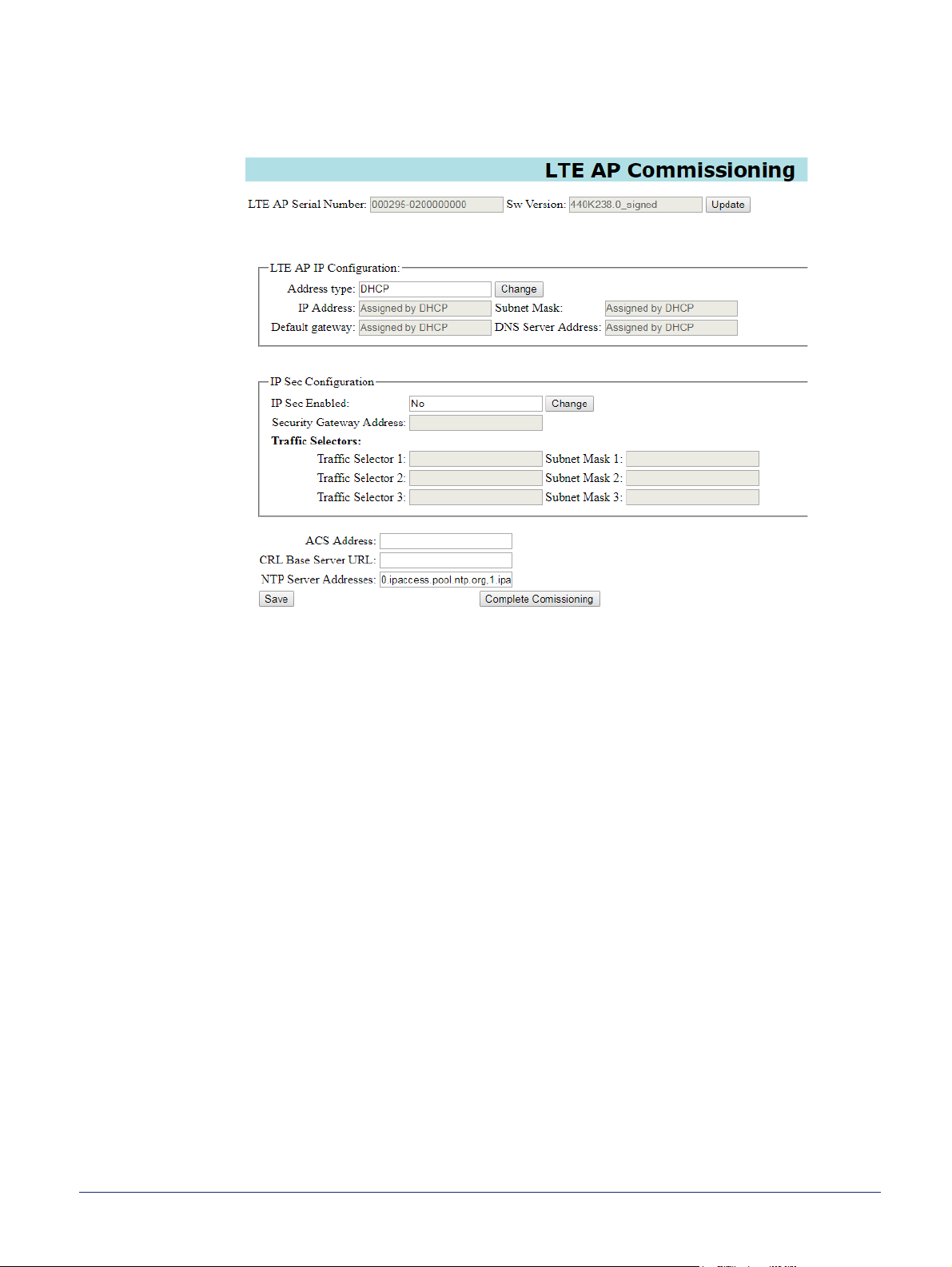
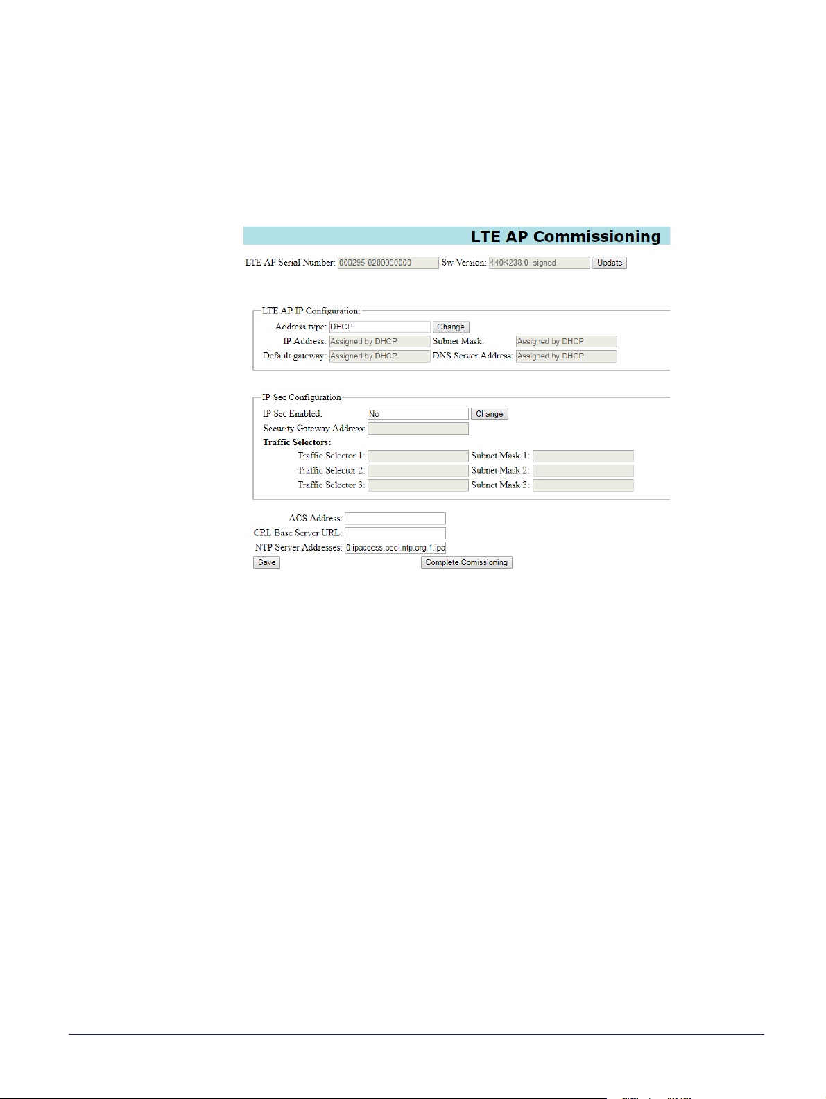
9) Enter the commissioning user name and the password (supplied separately for
security reasons). After entering the correct user name and password, the LTE AP
Commissioning page appears:
3.5 Optional - Software Download
If it is necessary to download a software package to the AP, this must be done before
configuring the connection to the NOS Server.
This can only be done if the commissioning terminal is running a web server that provides a
path to any ip.access AP software download packages. That is, the required .sdp files must
be present on the commissioning terminal.
Setting up a web server for this purpose on the commissioning terminal is outside the scope
of this manual.
Use the SW Download page to:
• Inspect the current version of software that the LTE AP is running.
• Download a new version of AP software to the LTE AP from the commissioning
terminal to the standby memory bank. The LTE AP reboots to the new version of
software when the download is complete and verified.
1) If it has not already been done (as in section 3.2), ensure the LTE AP has updated
its clock time with NTP and also updated its "last known time". This must be done
before downloading any new software to the LTE AP. To do this, connect the LTE
AP to the Internet and reboot it. The LTE AP must be left in this state for an hour to
ensure it updates its "last known time", which is preserved when the LTE AP is
restarted again to reenter the commissioning web page. Then reconnect the LTE
AP to the commissioning terminal and restart the web page.
nanoLTE E61 AP Hardware Installation nanoLTE E61 AP Commissioning
NANO_INST_43325 v205_0.6 for N4G_2.5 © ip.access Limited 2019 Page 17
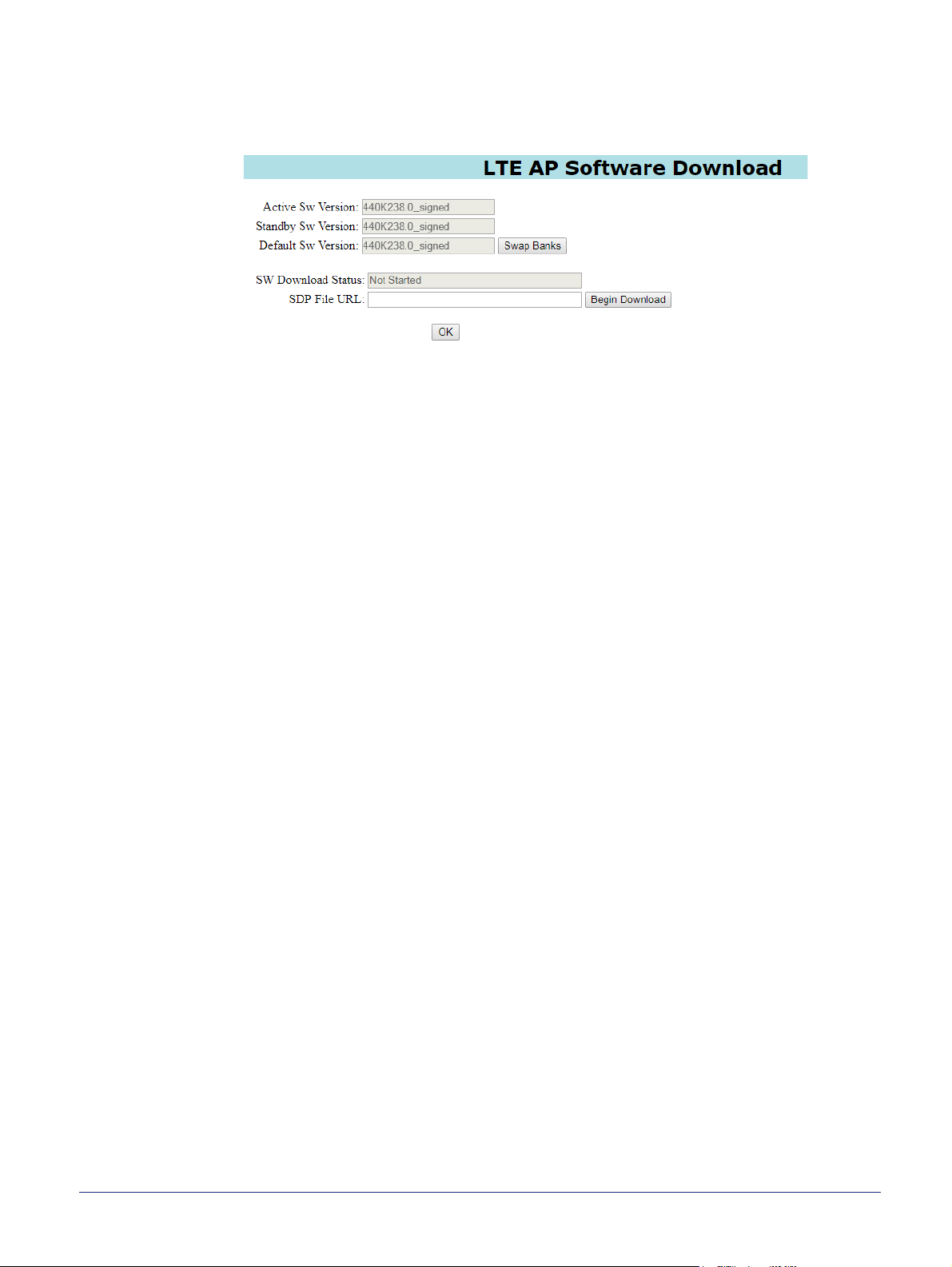
2) Near the top of the main page, click the Update button next to the current software
version. The web page for downloading software will be shown. This also provides
full details about the current software installed on the LTE AP. For example:
3) In the SDP File URL text box, enter the URL for the SDP file stored on the
commissioning terminal. For example:
http://192.168.0.2/webservername/440K007_<ver>_signed.sdp
Where <ver> is the actual build version of the required software package.
4) Click Begin Download.
5) Wait about a minute for the download to take place.
6) To restart the LTE AP from the new software just downloaded, briefly press the
corresponding reset button on the back of the AP.
7) Once the LTE AP has started, repeat the procedure in section 3.4 to perform a
factory reset and access the login prompt to login again with the commissioning
user name and password.
8) Click the SW Download link on the left.
9) Inspect the software version information to verify that the LTE AP has booted from
the downloaded software.
10) To ensure the standby bank also has the latest software version, repeat the
software download, but do not restart the LTE AP. It is not necessary to restart the
LTE AP once it is already running the updated software.
This ensures the LTE AP does not have old software on the standby bank. Hence,
if the LTE AP is commanded to switch banks, it will run up-to-date software.
nanoLTE E61 AP Hardware Installation nanoLTE E61 AP Commissioning
NANO_INST_43325 v205_0.6 for N4G_2.5 © ip.access Limited 2019 Page 18
3.6 Configure the Connection to the NOS Server
3.6.1 Static IP Configuration
Obtaining an IP address with DHCP is recommended for the E61 AP, and this is selected
by default. Only execute this section if static IP configuration is needed. Do this first.
11) If static IP is required, click the Change button next to the Address Type box.
12) Edit the IP Address, Subnet Mask, Default Gateway and DNS Server Address
parameters as needed.
3.6.2 Configure IPsec
When commissioning an LTE AP with the web page, IPsec is disabled by default.
Note: If IPsec is not required, also ensure that the LTE AP is pre-provisioned in the NOS with
IPsec turned off in the AP configuration stored in the NOS.
If IPsec is required, update the configuration as follows:
1) Click the Change button next to the IPsec Enabled box. The IPsec parameters
become available.
2) Enter the address for the IPSec Gateway and the Traffic Selector addresses and
subnet masks.
ALERT: If the IPsec connection is towards an ACME SeGW the Traffic Selector
IP Addresses and Subnet Masks must all be left as 0.0.0.0.
nanoLTE E61 AP Hardware Installation nanoLTE E61 AP Commissioning
NANO_INST_43325 v205_0.6 for N4G_2.5 © ip.access Limited 2019 Page 19

3.6.3 Configure the TR-069 Management Connection
3) Enter addresses for the NOS Server (or equivalent TR-069 ACS) in the ACS
Address field.
4) In the CRL Base Server URL, enter the URL for contacting a CRL mirror server.
Note: This is the "base URL" as the AP constructs a full URL of the CRL update
file to obtain on contacting the server.
5) In the NTP Server Addresses box, enter a comma separated list of the four valid
NTP server addresses that will be accessible to the AP via its backhaul network. If
the backhaul will use the Internet, these can be NTP servers on the public Internet.
Note: The NTP and CRL servers must be accessible to the AP on start up,
before it has established an IPsec tunnel to the IPsec Gateway.
Note: If the AP can connect to the Internet, the default "0.ipaccess.pool.ntp.org"
may only be used as an initial value. The final configuration of an
operational AP (as supplied from the NOS or other TR-069 ACS) must not
use the ip.access pool.
Note: To provide AP crystal discipline, the final configuration of the NTP servers
must comprise four stratum 1 time servers.
6) To save the configuration, click the Save button.
The settings applied on this page are retained permanently as the default set of
these parameters in the TR-196 data model, and can only be subsequently
changed on this web page from a commissioning terminal or from the Redirector
by assigning the AP to a different set of DOCP parameters.
Note: At this point it may be useful to make a note of the parameter values
entered in this screen. Alternatively, save a screenshot of the web page
(information about how to take a screenshot is outside the scope of this
manual).
3.6.4 Complete the LTE AP Commissioning
7) To start the LTE AP in normal operation mode, click Complete Commissioning.
8) Acknowledge the warning about changes in the IP configuration and click OK.
9) When the initial configuration is complete, power off the AP and disconnect it from
the commissioning terminal.
At this point, the commissioning web page is no longer accessible. If there are
configuration errors that prevent the AP connecting to its serving NOS Server, the
commissioning web page must be started again after resetting the AP with a
factory reset. See section 5.3 for factory reset instructions.
nanoLTE E61 AP Hardware Installation nanoLTE E61 AP Commissioning
NANO_INST_43325 v205_0.6 for N4G_2.5 © ip.access Limited 2019 Page 20

3.7 Commissioning Complete
Commissioning the LTE AP is now finished.
From this point on, the LTE AP must be managed from the NOS Client, via the NOS Server.
If the LTE AP has not been pre-provisioned in the NOS Server, it must be pre-provisioned
and configured before it is can enter service.
For information about LTE AP pre-provisioning, see [INST_13400].
3.7.1 Completed On Site Commissioning
If commissioning has been done on site, continue to the on-site hardware installation
procedure (section 4).
Note: The on-site network connection to the LTE AP must also allow a path to the Redirector.
3.7.2 Completed Commissioning in Advance
If commissioning has been done in advance of sending the AP on site, it is advisable to
ensure that the LTE AP will connect to its serving NOS Server prior to sending the AP on
site. To do this:
1) Verify that the LTE AP has been pre-provisioned in the serving NOS.
2) Provide the LTE AP with an appropriate network connection. If the LTE AP has
been commissioned to use IPsec, this means a network connection that will go via
the IPsec Gateway, which is likely to require connection of the LTE AP to an
external network.
Note: The network connection to the LTE AP must also allow a path to the
Redirector.
3) Power up the AP.
4) Use the NOS Client to verify that the LTE AP has connected to its serving NOS.
When the blue delta symbol against the AP object disappears this means that the
LTE AP has connected to the NOS and has also updated its configuration.
5) After verifying this, re-pack the AP so that it is ready for delivery to its intended site.
nanoLTE E61 AP Hardware Installation nanoLTE E61 AP Commissioning
NANO_INST_43325 v205_0.6 for N4G_2.5 © ip.access Limited 2019 Page 21

4 nanoLTE E61 AP Hardware Installation
The topics in this section are:
• 4.1 Unpack the E61 AP
• 4.2 Cable Connections
• 4.3 Mount the E61 AP on a Wall or Ceiling
4.1 Unpack the E61 AP
1) Unpack the AP and its accessories.
Box contents may vary, but typically the box should contain the following:
• E61 AP unit with mounting bracket attached
• Extraction tool for removing the AP from its mounting bracket
• Mains power adaptor unit
• Set of 4 screws and wall plugs for the mounting bracket
Note: The screws and wall plugs are suitable for solid walls. It may be
necessary to source alternative fixings if they are not suitable for the type
of wall material on site.
2) Check that the serial numbers on the AP unit match the label on the box.
3) Check that the items have not been damaged in transit.
For any damaged units, contact the supplier immediately for returns advice.
nanoLTE E61 AP Hardware Installation nanoLTE E61 AP Hardware Installation
NANO_INST_43325 v205_0.6 for N4G_2.5 © ip.access Limited 2019 Page 22

4.2 Cable Connections
12V PSU
Mains
Input
LAN Cable to nearest switch/gateway
(max 100m)
12V DC
Cable to AP
(Approx 1.5m)
E61 AP
Switch/Router
Backhaul
Network
The AP requires power and an Ethernet connection. These can be provided discretely from
a power adaptor (as supplied) and a standard CAT5 Ethernet cable or with a single
Ethernet cable carrying PoE+.
Two power supply modules are available from ip.access, designed for use with the
ip.access E61 AP, that are compliant with the IEEE 802.3at standard:
• Direct power from the supplied mains power adapter
• Optionally, a PoE+ injector, commonly used for single site installations, which must
be ordered separately
Alternatively, power the E61 AP from a PoE+ switch.
4.2.1 PSU and LAN
When a suitable PSU is used to power the AP the PoE+ injector unit is not needed.
However, this means that a mains socket providing power to the AP must be within reach of
the cabling included with the PSU. This is typically about 1.5m. The PSU for the E61 AP is
supplied as standard.
nanoLTE E61 AP Hardware Installation nanoLTE E61 AP Hardware Installation
NANO_INST_43325 v205_0.6 for N4G_2.5 © ip.access Limited 2019 Page 23

4.2.2 Optional PoE+ Injectors
PoE+ Injector
PoE+
Mains
Input
Maximum total cable length between nearest
switch/gateway and AP is 100m
LAN Cable to nearest
switch/gateway
Switch/Router
Backhaul
Network
LAN Cable carrying PoE+
(max 100m to the PoE+ switch/router)
PoE+ Switch/Router
Backhaul
Network
The AP can be up to 100m from the switch/gateway to the backhaul, but allow
approximately 0.1m for routing through the injectors. The injectors can be positioned
anywhere on this cable run. Hence the injectors can be at the most convenient point for
providing power, without restricting the location of the AP.
The injectors take a direct mains input using the supplied mains cable. Use a CAT5
Ethernet cable that is capable of carrying PoE+ from each injector to the AP.
E61 AP
4.2.3 PoE+ Switch
In this case, the PoE+ switch is a third-party item. The cable run from the switch to the AP
can be a full 100m.
A PoE+ switch is typically used if there are multiple APs on site and/or there is other
equipment that can take advantage of PoE+.
4.2.4 GPS Source
The E61 AP includes an MCX connector for optionally using a GPS source for frequency
discipline.
The E61 AP does not have an internal GPS antenna. Hence, to use GPS for frequency
discipline, an external source must be provided, which can be a dedicated GPS antenna or
an equivalent source such as a distributed GPS system.
E61 AP
nanoLTE E61 AP Hardware Installation nanoLTE E61 AP Hardware Installation
NANO_INST_43325 v205_0.6 for N4G_2.5 © ip.access Limited 2019 Page 24

4.3 Mount the E61 AP on a Wall or Ceiling
Note: The E61 AP should be installed in a position so that it is at least 2m away from the area
where handsets are normally used.
The location of each E61 AP should be shown on an installation floor plan produced at the
network planning stage. For example, it must take into account that all APs must be at least
2m from any mobile equipment. The network wiring must be complete before the E61 AP
can be installed. The E61 AP should be placed on a wall or ceiling at or above head height,
at a minimum height of 1.8m.
1) Remove the mounting bracket from the E61 AP. Lay the AP on a flat surface with
the mounting bracket upwards. Slide the removal tool over the central guide
groove over the fin between the bracket and the body of the unit to disengage the
locking spring, then slide the bracket to separate it from the AP. The removal tool
may be inserted from the top or bottom of the AP.
2) Position the bracket on the wall or ceiling with its flat side against the wall or
ceiling. For wall mounting, orient the clip part towards the top. Ensure the bracket
is level and sufficient clearance is maintained to allow the AP to be fitted to the
bracket.
For wall mounting, allow at least 100mm from the bracket to the top of wall, and
150mm from the side of the bracket to any side walls, as illustrated:
For ceiling mounted APs, allow 150mm clearance on all sides:
nanoLTE E61 AP Hardware Installation nanoLTE E61 AP Hardware Installation
NANO_INST_43325 v205_0.6 for N4G_2.5 © ip.access Limited 2019 Page 25

3) Mark the position of the four screw holes.
4) Drill the four holes in the positions marked previously and insert wall plugs (if
required) and fix the mounting bracket securely to the wall or ceiling.
5) Before fitting the AP onto the bracket, plug in the required cables. Plug the
Ethernet cables from a switch/gateway into the RJ45 sockets. If the Ethernet
cables do not carry PoE+, also plug the power supply into the +12V DC input. Also,
if required, connect a GPS source to the GPS port.
6) Position the E61 so that the rear lugs line up to the gaps on the side rails of the
bracket, then push the S62 AP onto the bracket and slide the AP until the retaining
spring engages the indent at the rear of the unit.
nanoLTE E61 AP Hardware Installation nanoLTE E61 AP Hardware Installation
NANO_INST_43325 v205_0.6 for N4G_2.5 © ip.access Limited 2019 Page 26

5 Troubleshooting
This section covers the following topics that may be useful for troubleshooting an E61 AP
during installation:
• 5.1 E61 AP Does Not Power Up
• 5.2 E61 AP LEDs
• 5.3 Factory Reset
5.1 E61 AP Does Not Power Up
Check the following:
• Verify the correct power supply is in use and that mains power is available.
or
• Ensure that the Ethernet socket has PoE+ (PoE Plus, not PoE) to power the AP.
5.2 E61 AP LEDs
The front of the E61 has status LEDs:
Note: The Ethernet port on the back of the E61 AP has a link activity LED that flashes when there
is activity on the network connection. The LED is always off when the network cable is
unplugged.
nanoLTE E61 AP Hardware Installation Troubleshooting
NANO_INST_43325 v205_0.6 for N4G_2.5 © ip.access Limited 2019 Page 27

The nanoLTE E61 AP has the following LEDs:
LED Colour Description
Off The S2D is not switched on.
Green The LED may be Red or Green during the first 2 seconds after
Power
Service
powering up, while the
indicates that the AP is powered up normally.
Red The LED should only be Red briefly once the 2 second
initialization period is complete. If the LED continues to stay
Red after this, this means there is a fault with the AP.
After the 2 second initialization period, if the LED turns Red
after previously turning Green, this means that there is a
hardware power fault with the AP.
Off The LTE AP is not provisioned, it has no IP address. This may
be a temporary condition when the LTE AP is switched on for
the first time, or after factory reset.
Red Service not available because the LTE AP is administratively
locked (from the NOS).
Red flashing There is an error condition. Usually this means that the cell is
also down.
E61 AP is initializing. After this, Green
Connection
Mode
Flashing green
(1800ms on, 200ms
off), Red off
Green flashing
(500ms on, 500ms
off), Red off
Green flashing(50ms
on, 50ms off), Red off
Green flashing(50ms
on, 200ms off), Red
off
Off The LTE AP does not yet have an IP address. This should
Red If this LED has previously been Green, Red means that there
Green Flashing Green indicates the LTE AP is acquiring NTP or
Green This LED will always be Green to indicate that the LTE AP is
Cell down, service not available.
Cell locked, service not available.
Normal reboot, when reset button pressed for less than 5
seconds.
Factory reset, when reset button pressed for more than 5
seconds.
change shortly after the AP is switched on.
is an error, such as the LTE AP losing its IPsec connection
with the IPsec Gateway.
connecting to its IPsec Gateway. Steady Green indicates the
LTE AP is connected to its serving IPsec Gateway.
operating in LTE TDD mode. This LED may be off or amber
temporarily during startup.
nanoLTE E61 AP Hardware Installation Troubleshooting
NANO_INST_43325 v205_0.6 for N4G_2.5 © ip.access Limited 2019 Page 28

LED Colour Description
Off The LED is Off if the AP has not yet achieved GPS lock or if
the AP has lost GPS lock.
Note: If the AP is configured to use GPS synchronisation, it
GPS
Green This LED is Green when the AP has achieved GPS lock. The
will not start transmitting if it cannot obtain GPS lock and
similarly will stop transmitting if it loses GPS lock.
E61 AP has a GPS connector on the back panel for an
external GPS antenna.
nanoLTE E61 AP Hardware Installation Troubleshooting
NANO_INST_43325 v205_0.6 for N4G_2.5 © ip.access Limited 2019 Page 29

5.3 Factory Reset
First ensure that all other possibilities have been explored and eliminated before trying to
Factory Reset the AP.
A factory reset will clear the AP’s configuration, for example as supplied to the AP by the
NOS (or TR-069 ACS if the NOS is not used). Hence the AP will be reset to the following
configuration after a factory reset:
• Factory configuration data that cannot be removed, which includes:
• The AP’s Equipment ID (EID)
• The FQDN for the ip.access NTP services hosted by ntp.org
• The FQDN of the primary ip.access CRL mirror server
5.3.1 E61 AP Factory Reset
1) Press and hold the Reset switch.
Ensure that any implement used to press the button will not cause a static
discharge that may damage components on the board.
2) Hold the Reset button for at least 5 seconds, then release the button and the AP
will perform its Factory Reset.
If the Reset Switch is pressed for less than 5 seconds, this will only reboot the AP.
3) The Service LED blinks fast (50ms on, 50ms off) until the factory reset
commences, then it blinks slowly (50ms on, 200ms off). When the factory restore
process is complete, the LED extinguishes and the AP automatically reboots.
nanoLTE E61 AP Hardware Installation Troubleshooting
NANO_INST_43325 v205_0.6 for N4G_2.5 © ip.access Limited 2019 Page 30
6 AP and PSU Regulatory Information
This chapter provides the customer with safety and regulatory warnings, cautions and
information for the ip.access Ltd range of products.
• 6.1 Warnings and Cautions - nanoLTE E61 AP
• 6.2 Warnings and Cautions - Optional Power Supply Unit
• 6.3 Regulatory Statements for the E61 AP
• 6.4 Regulatory Statements for PSU
6.1 Warnings and Cautions - nanoLTE E61 AP
Electrical Safety
CAUTION
The AP is intended for dry indoor applications only. If evidence of condensation is
present do not apply power to the AP.
CAUTION
The AP is designed to be operated as a fixed system device and must be located
away from the user. It must be mounted in a manner to ensure that all users and
bystanders are kept a minimum of 20cm away from the connected antennas at all
times.
WARNING
Do not immerse any part of the AP in water or any other liquid. Do not install or use the
AP near open water. Do not spill liquids of any type on the AP.
WARNING
Do not use liquid, solvent or aerosol cleaning agents on or near the AP.
CAUTION
To avoid the risk of fire and/or electrical shock, do not push objects through openings
into the AP. The only exception is the recess for the Reset switch.
CAUTION
Do not disassemble the AP.
CAUTION
Before connecting a power supply the AP, verify that the power supply meets the
power requirements of the AP.
CAUTION
To avoid the risk of fire and/or electrical shock, do not overload power outlets or
extension cables.
Interference with Electronic Devices
CAUTION
If using a pacemaker, ensure you are using the device in accordance with its safety
requirements with respect to RF devices. Consult your doctor if you have questions
about RF signals and your pacemaker.
nanoLTE E61 AP Hardware Installation AP and PSU Regulatory Information
NANO_INST_43325 v205_0.6 for N4G_2.5 © ip.access Limited 2019 Page 31
CAUTION
If using a hearing aid, RF devices may cause interference.
CAUTION
Unshielded electronic devices should not be used near the AP. Conversely, the AP
should not be installed adjacent to unshielded electrical or electronic devices (such as
unshielded speakers).
Other Warnings and Cautions
WARNING
Do not install the AP in a position where any connected cables may cause a tripping or
choking hazard.
WARNING
Do not install the AP on an unstable surface. All caution must be observed to prevent
the device from falling and causing injury to a person and/or damage to the device.
WARNING
The AP should not be disposed of in household waste bins. Please follow local
regulations for disposal of electronic devices.
CAUTION
Do not install the AP in a position where any connected cables may be damaged by
walking on the cables.
nanoLTE E61 AP Hardware Installation AP and PSU Regulatory Information
NANO_INST_43325 v205_0.6 for N4G_2.5 © ip.access Limited 2019 Page 32

6.2 Warnings and Cautions - Optional Power Supply Unit
This section is only applicable when the optional power supply unit (PSU) is supplied with
the E61 AP.
Electrical Safety
WARNING
Do not immerse any part of the power supply in water or any other liquid. Do not install
or use the power supply near open water. Do not spill liquids of any type on the power
supply.
WARNING
Do not use liquid, solvent or aerosol cleaning agents on or near the power supply.
CAUTION
To avoid the risk of fire and/or electrical shock, do not push objects through openings
into the power supply.
CAUTION
Do not disassemble the power supply.
CAUTION
Before using the power supply, verify that the mains voltage is within the range
specified by the voltage printed on the power supply.
CAUTION
When supplied, the PSU supplied with the AP must not be used for powering any
other equipment.
CAUTION
To avoid the risk of fire and/or electrical shock, do not overload power outlets or
extension cables.
CAUTION
When disconnecting the power supply from the mains, pull the plug. Pulling the cable
may result in damage to the cable.
Other Warnings and Cautions
WARNING
Do not install the power supply in a position where the cable may cause a tripping or
choking hazard.
WARNING
Do not install the power supply on an unstable surface. All caution must be observed
to prevent the device from falling and causing injury to a person and/or damage to the
device.
WARNING
The power supply should not be disposed of in household waste bins. Please follow
local regulations for disposal of electronic devices.
CAUTION
Do not install the power supply in a position where the cable may be damaged by
walking on the cable.
nanoLTE E61 AP Hardware Installation AP and PSU Regulatory Information
NANO_INST_43325 v205_0.6 for N4G_2.5 © ip.access Limited 2019 Page 33

6.3 Regulatory Statements for the E61 AP
6.3.1 US FCC Compliance
• FCC CFR47 Parts 15B, 2, 96
Note: Changes or modifications not expressly approved by the party responsible for compliance
may void the user's authority to operate this equipment.
Model LTE Band FCC ID
nanoLTE E61 AP Model 495X 48 (CBRS) QGGIPA495X
WARNING
This is a class B product. In a domestic environment this product may cause radio
interference in which case the user may be required to take adequate measures.
Note: This equipment has been tested and found to comply with the limits for a Class B digital
device, pursuant to part 15 of the FCC Rules. These limits are designed to provide
reasonable protection against harmful interference in a residential installation. This
equipment generates, uses and can radiate radio frequency energy and, if not installed and
used in accordance with the instructions, may cause harmful interference to radio
communications. However, there is no guarantee that interference will not occur in a
particular installation. If this equipment does cause harmful interference to radio or
television reception, which can be determined by turning the equipment off and on, the user
is encouraged to try to correct the interference by one or more of the following measures:.
• Reorient or relocate the receiving antenna.
• Increase the separation between the equipment and receiver.
• Connect the equipment into an outlet on a circuit different from that to which the
receiver is connected.
• Consult the dealer or an experienced radio/TV technician for help.
6.3.2 Safety Standards
The E61 unit has passed safety testing in accordance with IEC/UL 62368-1.
6.3.3 Environmental Standards
• Type: Indoor
• Storage: Weather Protected, Partly Temperature controlled Class 1.1 - ETSI
300-019-1-1
• Transport: Public Transport Class 2.3 - ETSI 300-019-1-2
• Operation: Partly Temperature controlled locations Class 3.2 - ETSI
300-019-1-3
nanoLTE E61 AP Hardware Installation AP and PSU Regulatory Information
NANO_INST_43325 v205_0.6 for N4G_2.5 © ip.access Limited 2019 Page 34

6.3.4 RF Exposure Statement
This equipment complies with radiation exposure limits set forth for an uncontrolled
environment and meets radio frequency (RF) Exposure Guidelines for base stations. This
equipment should be installed and operated keeping the product 20cm or more away from a
person's body.
nanoLTE E61 AP Hardware Installation AP and PSU Regulatory Information
NANO_INST_43325 v205_0.6 for N4G_2.5 © ip.access Limited 2019 Page 35

6.4 Regulatory Statements for PSU
Safety Approvals cUL/UL
SAA
CE
C-Tick
Mechanical Characteristics Length: 82.7mm (3.26in)
Width: 55mm (2.17in)
Height: 39.1mm (1.54in)
Weight: 150g (5.29oz)
PSAA30R Characteristics
AC Input Voltage Rating 100 to 240V AC
Emissions FCC Class B
EN55022 Class B
AC Input Voltage Range 90 to 264V AC
Immunity IEC61000-4-2 Level 4
IEC61000-4-3 Level 2
IEC61000-4-4 Level 2
IEC61000-4-5 Level 2
IEC61000-4-6 Level 2
IEC61000-4-8 Level 1
IEC61000-4-11
ENC61000-3-2
AC Input Frequency 47 to 63Hz
Input Current 0.8A (RMS) maximum at 120V AC
0.5A (RMS) maximum at 240V AC
Leakage Current 0.25mA maximum
Over-Voltage protection Auto restart
Inrush Current <60A for 100V AC at maximum load
<100A for 240V AC at maximum load
(Cold start at ambient 25C)
Over-Current Protection Auto-restart without damage
Short-Circuit Protection Output can be shorted without damage
Input Power Saving 0.3W maximum at no load
Dielectric Withstand (Hi-pot) Test Input to Output: 3000V AC for 1 min., 10mA
Output Efficiency >83.5% average efficiency
Insulation Resistance Input to output: 7M ohm, 500V DC
Environmental Temperature Operation 0°C to +40°C
Non-operation -25 to +75C
Humidity 20 to 90%
DC Output Connector (Barrel Type) 2.1 x 5.5 x 9.5mm Center Positive Standard
nanoLTE E61 AP Hardware Installation AP and PSU Regulatory Information
NANO_INST_43325 v205_0.6 for N4G_2.5 © ip.access Limited 2019 Page 36

AC Input Clips RPA: US
6.4.1 Output Specification
RPB: Brazil
RPC: China
RPE: Europe
RPH: Korea
RPI: India
RPK: UK
RPN: Argentina
RPS: Australia
RPX: IEC320 C8
Model DC Output
Voltage
PSAA30R-120 12V 0A 2.50A 120mV +5% V
Load
Min Max
Ripple
P-P (max)
Regulation
Line / Load
Efficiency
Level
nanoLTE E61 AP Hardware Installation AP and PSU Regulatory Information
NANO_INST_43325 v205_0.6 for N4G_2.5 © ip.access Limited 2019 Page 37
 Loading...