

Page 1

The world's most deployed picocell
ip.access Ltd
Building 2020
Cambourne Business Park
Cambourne
Cambridgeshire
CB23 6DW
United Kingdom
nanoBTS Product Description
NGSM_GST_300 1.0m0.1 CP
Page 2

REVISION HISTORY
Version Change Summary Date Author
0.1 First draft 13 Jun 2008 AM4
0.2
0.3 Updated with comments from review 13 Oct 2008 MB3
1.0 Released 21 Nov 2008 ZN1
1.0m0.1 Added 165E/F/G/H information – CP DRAFT 30 Apr 2009 ZN1
Added details of 165 Series C/D, added the Safety and
Regulatory chapter, and removed the Profile chapters.
20 Oct 2008 MB3
DOCUMENT APPROVAL
Approved by e-mail.
The information contained in this document is commercially confidential and must
not be disclosed to third parties without prior consent.
Page 3

TABLE OF CONTENTS
1 INTRODUCTION.......................................................................................................1
1.1
Overview............................................................................................................1
1.2
Related Information............................................................................................1
1.3
Terminology.......................................................................................................1
2 SERIES MEMBERS...................................................................................................4
3 HARDWARE SPECIFICATION..................................................................................5
3.1
External..............................................................................................................5
3.1.1
Appearance (Informative)...........................................................................5
3.1.2
Size, Shape and Weight.............................................................................6
3.1.3
GSM Standards..........................................................................................7
3.1.4
Environmental ............................................................................................7
3.1.5
Ethernet Interface.......................................................................................7
3.1.6
DC Power...................................................................................................8
3.1.7
TIB (Timing Interface Bus)..........................................................................8
3.1.8
Antennas..................................................................................................10
3.1.9
LED Indicator............................................................................................12
3.1.10 Labelling...................................................................................................12
3.1.11 Chassis Bond Point..................................................................................12
3.2
Internal.............................................................................................................13
3.2.1
Power Supply...........................................................................................13
3.2.2
OCXO.......................................................................................................13
3.2.3
Backhaul Sub-System..............................................................................13
3.2.4
TRX Baseband Sub-System.....................................................................14
3.2.5
Transmitter...............................................................................................14
3.2.6
Receiver - uplink.......................................................................................15
3.2.7
Receiver - downlink..................................................................................15
4 MTBF.......................................................................................................................16
5 SOFTWARE SPECIFICATION................................................................................17
5.1
Top Level Feature Overview............................................................................17
5.2
Explicitly Not Supported...................................................................................18
5.3
Standards.........................................................................................................18
5.4
Reset Behaviour...............................................................................................18
5.4.1
Boot..........................................................................................................18
nanoBTS Product Description
© ip.access Ltd
Page 4

5.5
5.6
5.7
5.8
5.4.2
Software Code Banks and Software Bank Activation................................18
5.4.3
Reset Reason...........................................................................................19
Configuration....................................................................................................19
5.5.1
DHCP.......................................................................................................19
5.5.2
Fallback OML Link....................................................................................19
5.5.3
Management Model and Attributes...........................................................19
5.5.4
Code Download........................................................................................20
Air Interface......................................................................................................21
5.6.1
Channel Combinations.............................................................................21
5.6.2
Power Control and Handover ...................................................................21
5.6.3
Cell Broadcast..........................................................................................22
5.6.4
CCCH.......................................................................................................22
5.6.5
System Information...................................................................................22
Error Handling..................................................................................................22
System Monitoring ...........................................................................................23
5.8.1
SNMP Specific Features ..........................................................................23
5.8.2
LED States...............................................................................................24
5.9
Traffic...............................................................................................................27
5.9.1
Channel Types.........................................................................................27
5.9.2
Encryption................................................................................................27
5.9.3
Traffic Frame Formats..............................................................................27
5.10 Performance ....................................................................................................27
5.11 Peripherals.......................................................................................................28
5.11.1 Backhaul ..................................................................................................28
5.12 NV Configuration..............................................................................................28
5.12.1 Parameters...............................................................................................28
5.12.2 TRX Controlled Parameters......................................................................32
5.13 Operations .......................................................................................................32
5.13.1 Network Listen..........................................................................................32
5.13.2 Normal Operation.....................................................................................33
5.14 Abis Interface (ABIS)........................................................................................35
5.14.1 Operations and Maintenance Signalling Messages ..................................35
5.14.2 RSL Signalling Messages.........................................................................36
5.14.3 User Traffic Messages..............................................................................36
5.14.4 Channel Control Messages......................................................................36
5.15 GPRS Feature Support....................................................................................37
nanoBTS Product Description
© ip.access Ltd
Page 5

6 SOFTWARE IMPLEMENTATION (INFORMATIVE).................................................38
6.1
139/140 Platform..............................................................................................38
6.2
Functional Partitioning......................................................................................39
6.3
Interprocessor Communications.......................................................................40
6.4
Process Scheduling .........................................................................................40
6.5
Interprocess Communications and Synchronisation (139/140 units).................41
7 DHCP ......................................................................................................................42
8 CUSTOMER SAFETY AND REGULATORY INFORMATION..................................51
8.1
Introduction......................................................................................................51
8.1.1
Purpose and Scope..................................................................................51
8.1.2
Terminology..............................................................................................51
8.2
Model 109 Power Supply .................................................................................51
8.2.1
109 - Handbook - Warnings and Cautions................................................51
8.2.2
109 - Handbook - FCC Text......................................................................52
8.2.3
109 - Handbook - Industry Canada text....................................................52
8.2.4
109 - Handbook - Regulatory Compliance Statement...............................52
8.3
Model 126 Ethernet Switch and Power Inserter................................................53
8.3.1
126 - Handbook - Warnings and Cautions................................................53
8.3.2
126 - Handbook - FCC Text......................................................................54
8.3.3
126 - Handbook - Industry Canada text....................................................54
8.3.4
126 - Handbook - Regulatory Compliance Statement...............................55
8.4
nanoBTS Products...........................................................................................55
8.4.1
nanoBTS - Handbook - Warnings and Cautions.......................................55
8.4.2
nanoBTS - Handbook - Parts required for each nanoBTS ........................56
8.4.3
nanoBTS - Handbook - Provision of Power to the nanoBTS.....................56
8.4.4
nanoBTS - Handbook - FCC Text.............................................................58
8.4.5
nanoBTS - Handbook - IC Text ................................................................59
8.4.6
nanoBTS - Handbook - Regulatory Compliance Statement......................59
nanoBTS Product Description
© ip.access Ltd
Page 6

1 INTRODUCTION
1.1 Overview
This product description gives the technical specification of the 165 and 139/140 series
nanoBTSs from ip.access. It describes the basic properties and functionality of the
hardware and software. It includes information on the management model supported by
the BTS. It does not go into detail on GSM service support beyond the most basic. This is
described in the range of Feature Description documents also available from ip.access.
1.2 Related Information
[GSM05.05] 3GPP TS05.05; Technical Specification Group GSM/EDGE; Radio
Access Network; Radio transmission and reception (Release 1999)
[GSM05.08] 3GPP TS05.08; Technical Specification Group GSM/EDGE; Radio
Access Network; Radio Subsystem Link Control (Release 1999)
[REF_110] nanoGSM BSS MIB Definition (NGSM_REF_110)
[INST_300] nanoBTS Installation Manual (NGSM_INST_300)
[NGSM_SOC] nanoGSM Statements of Compliance, ip.access
[NGSM_APR] nanoGSM Approvals, ip.access
1.3 Terminology
AMR Adaptive Multi-Rate
ARFCN Absolute Radio Frequency Channel Number
AWG American Wire Gauge
BA list Basestation Allocation
Backhaul
processor
BHCA Busy-Hour Call Attempts
BSC Basestation Controller
BSIC Basestation Identity Code
BTS Base Transceiver Station
CA List Channel Allocation
CBCH Cell Broadcast Channel
CCCH Common Control Channel
CEM Contract Electronics Manufacturer
CGI Cell Global Identity
Codec Coder-Decoder
Synonym for PPC in this document
nanoBTS Product Description Introduction
© ip.access Ltd Page 1
Page 7

CRC Cyclic Redundancy Check
DAC Digital to Analog Converter
DHCP Dynamic Host Configuration Protocol
DLP
Downlink Processor (baseband processor responsible for transmit
processing)
Dongle Hardware plug used to reset the BTS to factory default settings
EEPROM Electrically Erasable Programmable Read Only Memory
EFR Enhanced Full Rate (GSM Speech coding)
ESD Electro-static Discharge
FCC Federal Communications Commission
FEC Fast Ethernet Controller, or Forward Error Correction
FER Failure Event Report
FPGA Field Programming Gate Array
FR Full rate (GSM Speech coding)
GPIO General Purpose Input-Output
GPRS General Packet Radio Service
HR Half Rate (GSM Speech Codec)
HTTP Hypertext Transfer Protocol
IP Internet Protocol
LED Light Emitting Diode
MAC
Media Access Control. Signifies a particular layer in the ANSI standard
protocol model for GPRS. Also used in this document in the phrase
"MAC Address"
MAC Address
The physical (hardware) address of the Ethernet interface. Ip.access has
its own MAC address range allocated by IEEE.
MS Mobile Station (= handset + SIM)
NACK Negative Acknowledge
NCELL Neighbour Cell
NV Non-volatile
NWL Network Listen
OCXO Oven Controlled Crystal Oscillator
OEMid Original Equipment Manufacturer Identifier
OML Operations and Maintenance Link
OOL Out-of-lock
OPLL Output PLL
PA Power Amplifier (final internal amplification stage in the nanoBTS)
PCB Printed Circuit Board
PCU Packet Control Unit
PLL Phase-Locked Loop
POST Power-on Self Test
PPC Power PC (particular device used for Ethernet interface processing)
nanoBTS Product Description Introduction
© ip.access Ltd Page 2
Page 8

RACH Random Access Channel
RSL Radio Signalling Link
SABM
Set Asynchronous Block Mode (a message indicating the establishment
of the radio data link)
SACCH Slow Associated Control Channel
SCH Synchronisation Channel
SDP
Software Download Package (proprietary format for software download
to the BTS)
SI System Information
SMS-CB Short-message service – cell-broadcast
SMS-PP Short-message service – point-to-point
SNMP Simple Network Management Protocol
SoLSA Support of Local Service Area
TA
Type Approval (an obsolete term used to signify testing against the
harmonised 3GPP compliance specifications for the purposes of CE
marking)
TCU
Timing and Control Unit (a subsystem of the nanoBTS baseband
processor)
TFTP Trivial File Transfer Protocol
TIB Timing Interface Bus
TRX Transceiver
UL Underwriters Laboratory
ULM Uplink Master (baseband processor responsible for receive processing)
ULS
Uplink Slave (baseband processor – controlled by ULM – also performing
receive processing)
VBS Voice Broadcast Services
VGCS Voice Group Call Services
nanoBTS Product Description Introduction
© ip.access Ltd Page 3
Page 9

2 SERIES MEMBERS
The 165 series consists of the following products for the GSM bands shown in brackets:
• 165A (DCS 1800)
• 165B (PCS 1900)
• 165C (EGSM 900)
• 165D (GSM 850)
• 165E (DCS 1800)
• 165F (PCS 1900)
• 165G (DCS 1800)
• 165H (PCS 1900)
The 139/40 series consists of the following products for the GSM bands shown in brackets:
• 139_ (DCS 1800)
• 140_ (PCS 1900)
• 177_ (GSM 850)
• 178_ (EGSM 900)
The band designator is as used in [GSM05.05].
nanoBTS Product Description Series Members
© ip.access Ltd Page 4
Page 10
3 HARDWARE SPECIFICATION
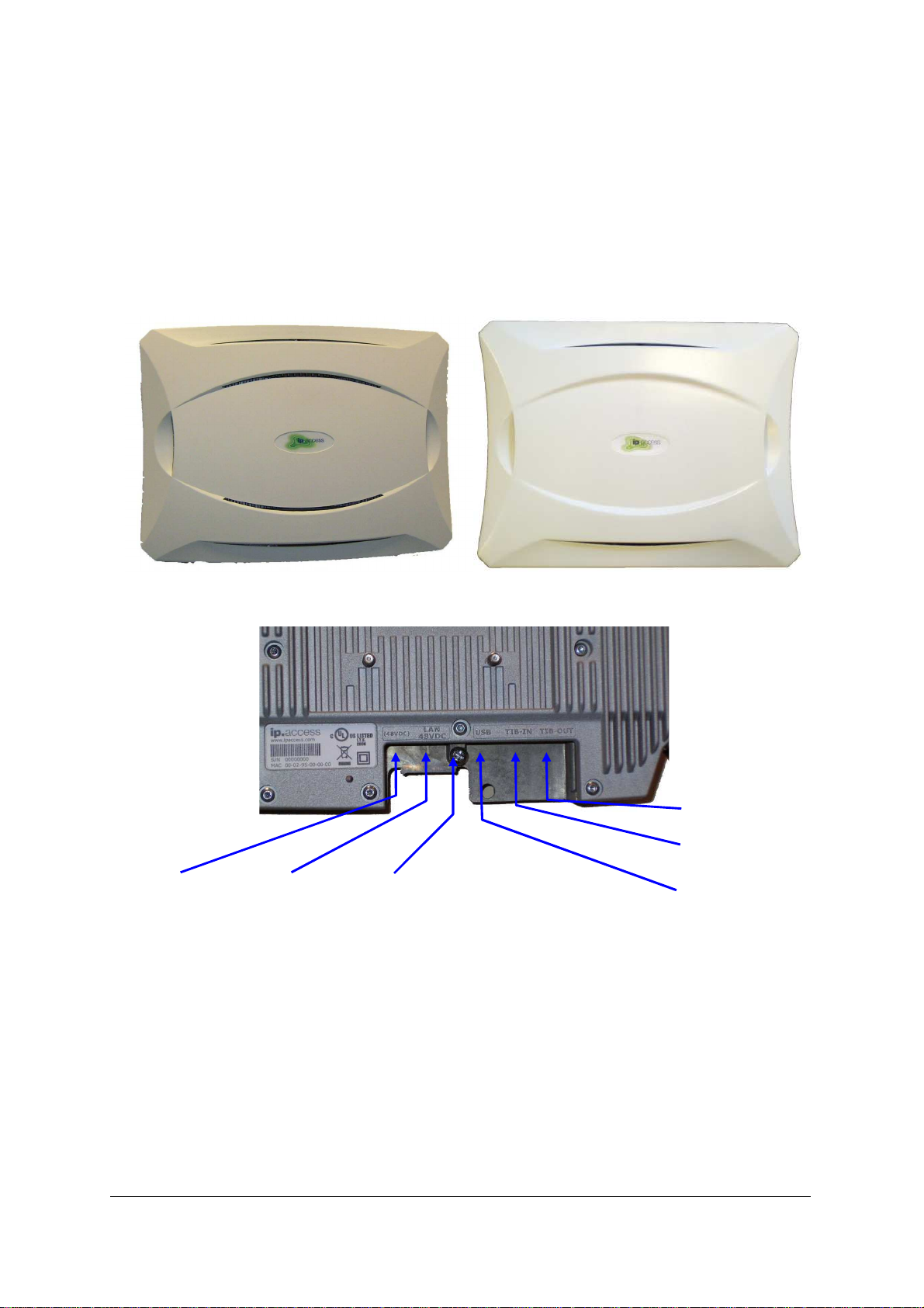
TIB in
3.1 External
3.1.1 Appearance (Informative)
The 165 series nanoBTS are shown in Figure 1 and Figure 2.
48v DC
Power Option
Figure 1 - 165A/B (EDGE) nanoBTS (left) and 165C/D/G/H (right)
Powered
Ethernet
Chassis
Bond
Figure 2 - 165 nanoBTS connectors
USB Port
(Not used)
TIB out
nanoBTS Product Description Hardware Specification
© ip.access Ltd Page 5
Page 11
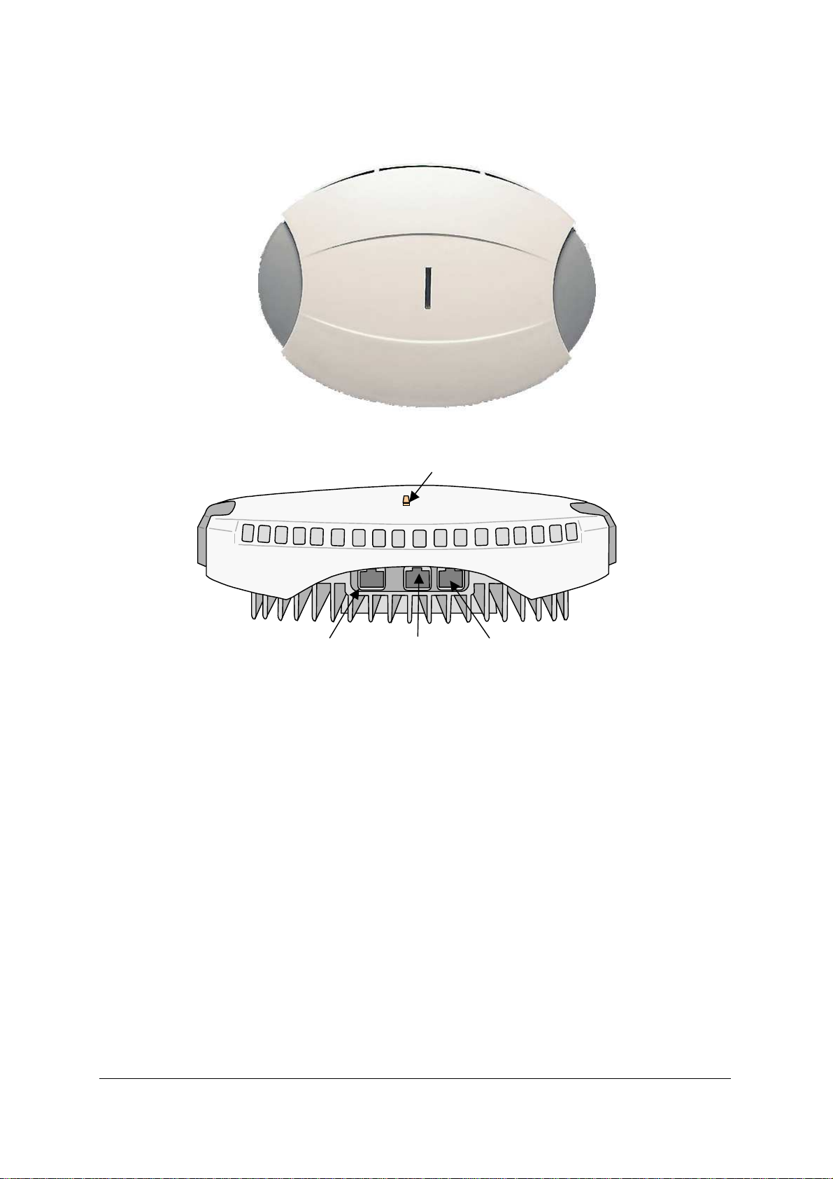
The 139/140 series nanoBTS is shown in Figure 3 and Figure 4.
Figure 3 - 139/140 nanoBTS
Status Indicator
RJ45(48Vdc)
Ethernet
Figure 4 - 139/140 nanoBTS connectors
TIB In TIB Out (26MHz)
3.1.2 Size, Shape and Weight
The 165A/B series nanoBTS fits in an envelope approximately 276mm long, 208mm wide
and 63mm deep. The plan shape is roughly rectangular. The 165C/D/G/H series nanoBTS
fits in an envelope approximately 291mm long, 222mm wide and 63mm deep. The plan
shape is roughly rectangular. These dimensions should not be used for space planning in
installation. See [INST_300] for more information on space requirements of the 165
series. The unit weighs less than 2kg. When used in multi-TRX deployments, two 165 units
may be mounted together in a "stacked" configuration (see [INST_300] for details).
The 139/140 series nanoBTS fits in an envelope approximately 275mm long, 210mm wide
and 75mm deep. The plan shape is roughly elliptical. These dimensions should not be
used for space planning in installation. See [INST_300] for more information on space
requirements of the 139 series. The unit weighs less than 3kg.
Heavy finning on the back of the unit is provided for convective cooling when vertically
mounted. When wall mounted, these fins are intended to be vertical.
nanoBTS Product Description Hardware Specification
© ip.access Ltd Page 6
Page 12

Fins are also provided on the front of the unit, normally obscured by the plastic cosmetic
cover. When ceiling mounted or in any other horizontal situation, the plastic cosmetic
cover is intended to be removed to allow airflow across the front fins.
3.1.3 GSM Standards
Standards Parts Date
3GPP 11.21 Essential Compliance v8.8.0
3GPP 05.05
EGSM, Power Class P1, as
v8.14.0
called up by 3GPP
11.21/Essential Compliance
ETS 301 489
Part 8 – specific requirements for
v1.1.1
GSM basestations
For a complete and normative statement of nanoGSM system approvals and standards
compliance, see [NGSM_SOC].
3.1.4 Environmental
Operational: Temperature
Humidity
Storage: Temperature
Humidity
Cold Start: Warm-up period from cold
Hot Start:
System reset without loss of power
supply
Standards:
ETS 300-019-1-1
ETS 300-019-1-2
ETS 300-019-1-3
-5 ~+45C ambient
5-90% non-condensing
-20 ~ +80C ambient
5-90% non-condensing
In-spec operation within 10
minutes
In-spec operation within 3
minutes
Storage Class 1.1
Transport Class 2.3
Operation Class 3.1
EN301-489-1
EMC general
EN301-489-8
EN301-502
EN60950 / IEC 60950 /UL60950 Safety
Note that the 139/140 and 165 series are not hermetically sealed.
See [NGSM_APR] for complete approvals and standards compliance documentation.
3.1.5 Ethernet Interface
The Ethernet connector is 8-way RJ-45 female (screened on the 165 C/D/G/H).
The Ethernet physical layer is 10/100baseT, full-duplex, auto-negotiate.
nanoBTS Product Description Hardware Specification
© ip.access Ltd Page 7
Page 13

3.1.6 DC Power
Power is expected by the unit on the Ethernet connector, according to IEEE802.3af option
B or A. Option A is implemented with Or-ing diodes from the unused wires, and results in
reduced supply margin and efficiency. Option B is preferred, therefore. See section 3.2.1
for more information.
The 139/140 series is designed to meet IEEE802.3af. Interoperability with 3rd party
802.3af supply equipment is not warranted. The unit is sold with its own mains power
supply (Product 109), which inserts power onto the Ethernet cable. In addition, the 165 unit
also has a separate connector for a 48V DC supply.
DC Power consumption is less than 13W.
3.1.7 TIB (Timing Interface Bus)
The TIB consists of two 10-way RJ45 connectors, a TIB-in and a TIB-out.
The TIB is required to synchronise the GSM frames between nanoBTS units acting
together as a single multi-TRX BTS. TIB-in accepts GSM-frame timing from a preceding
TRX and TIB-out generates it for the next TRX.
TIB-out
Current-mode LVDS drive, transformer coupled. Clock is
divided system clock (26MHz/16).
TIB-in
LVDS, internal termination gives typically 300mV peak-to-
peak when driven by TIB-out.
Reference Clock Input External reference clock (10MHz), with detect circuit.
Frame Sync Via removable link (for development / TA testing)
Security dongle
Support for detection of external dongle on TIB, connected
to GPIO on PPC.
Maximum TIB cable length 1.5m
Drive control
Clock output to be enabled by software. This facilitates
detecting position within a chain of BTS’s.
Serial Interface From PPC / ULM (via link on PCB).
FPGA Serial Output For development logging output (via link on PCB).
TIB Spare 1 and 2 From FPGA (via link on PCB).
Connector
10 way RJ-45 with polarisation key to prevent insertion of
standard Ethernet connector. Connectors and internal
circuitry tolerant to hot insertion, removal and reversal of TIB
in and TIB out cables.
Accessibility Accessible in-situ. No protective cover.
ESD protection
Protected to Human Body / Equipment Level discharges and
line induced surges. Protected against forced insertion of
48V Ethernet into TIB connectors, when debug links
removed.
nanoBTS Product Description Hardware Specification
© ip.access Ltd Page 8
Page 14

TIB out
1 TIB SPARE 1 (to FPGA via link on PCB)
2 TIB SPARE 2 (to FPGA via link on PCB)
3 26MHz OUT 4 26MHz OUT +
5 GSM SYNC OUT +
6 GSM SYNC OUT 7 PPC Serial interface OUT (via link on PCB)
8 PPC Serial interface IN (via link on PCB)
9 FPGA SERIAL OUT (via link on PCB)
10 Ground
TIB in
1 10MHz IN2 10MHz IN+
3 26MHz IN4 26MHz IN+
5 GSM SYNC IN+
6 GSM SYNC IN7 TRX FRAME SYNC (via PCB link)
8 Not connected
9 Security
10 Ground
nanoBTS Product Description Hardware Specification
© ip.access Ltd Page 9
Page 15
3.1.8 Antennas
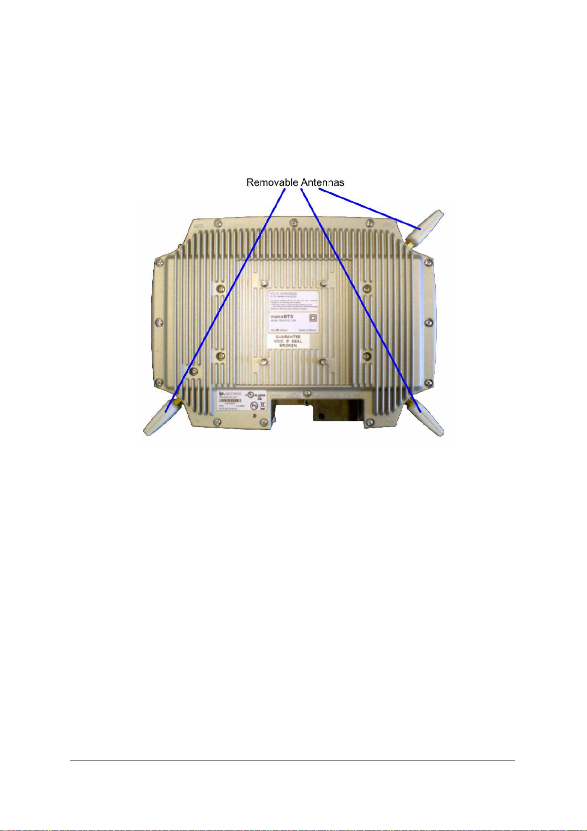
165 nanoBTS units provide SMA connectors that are exposed when the antennas are
unscrewed as illustrated in Figure 5. (The removable antennas for 165C, 165D, 165G and
165H are shown in Figure 5. The removable antennas for 165A and 165B are smaller.
165E and 165F have no removable antennas.)
Figure 5 - Removable antennas – 165 hardware
The 139/140 series is normally used with its own internal antennas, of which there is one
for transmit and one for receive. The units can be supplied with an optional external
antenna kit, which allows the unit to be connected to an external duplexer, booster system,
distributed antenna system or other external radio system (not supplied by ip.access). See
[INST_300] for more details on the external antenna kit.
Figure 6 shows the 139/140 unit with external antenna kit fitted.
The external antenna kit introduces negligible loss, so the transmitter and receiver
specifications given in sections 3.2.5, 3.2.6 and 3.2.7 apply equally at the external antenna
ports.
nanoBTS Product Description Hardware Specification
© ip.access Ltd Page 10
Page 16
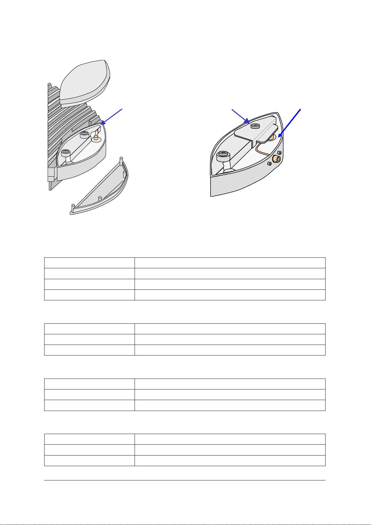
Antenna Cover
Top
Notch to aid
removal of
cover
Antenna Cover
Body
Antenna Cover
Bottom
3.1.8.1 165 Antennas
Clamp plate
Figure 6 - External antenna kit
Compression
Spring
Internal receive aerial 0 dBi nominal screw-on SMA omni-directional
Internal transmit aerial 0 dBi nominal screw-on SMA omni-directional
Internal NWL aerial 0 dBi nominal screw-on SMA omni-directional
Isolation (Tx to Rx) 30dB
3.1.8.2 139/140 Internal Antennas
Internal receive aerial 0 dBi nominal printed omni-directional
Internal transmit aerial 0 dBi nominal printed omni-directional
Isolation (Tx to Rx) 30dB
3.1.8.3 165 External Antenna Ports
Provision Remove existing antennas to expose SMA connectors
Connectors SMA female
ESD Protection None – external cavity duplexer required
3.1.8.4 139/140 External Antenna Ports
Provision Option kit – one connector each for transmit and receive
Connectors SMA female
ESD Protection None – external cavity duplexer required
nanoBTS Product Description Hardware Specification
© ip.access Ltd Page 11
Page 17

3.1.9 LED Indicator
Two LEDS are provided on the PCB. These can provide three colours (red, green,
orange) in various flash codes, as specified in section 5.8.2.
3.1.10 Labelling
TA/CE certification
Product 139
Product 165A
Product 165E
CE mark with associated devices.
(FCC not appropriate for 1800MHz devices)
Product 165G
Product 140
Product 165B
Product 165F
FCC mark with associated devices.
UL mark with associated devices.
(CE not appropriate for 1900MHz devices)
Product 165H
Product 177
Product 165D
FCC mark with associated devices.
UL mark with associated devices.
(CE not appropriate for 850MHz devices)
Product 178
Product 165C
CE mark with associated devices.
(FCC not appropriate for 900MHz devices)
Product identification
Ip.access serial number in text and bar code, product code in
text only
MAC address In text and bar code
Positioning Visible when mounted. Not positioned on front face.
OEM label Subject to separate specification and positioning
3.1.11 Chassis Bond Point
139/140 Located on rear of BTS
165 Located on front of BTS
Multi-TRX operation
Cable length
nanoBTS Product Description Hardware Specification
© ip.access Ltd Page 12
BTS’s must be connected with 16AWG bonding cables
when operated as a multi-TRX.
Maximum cable length is 1.5m. Cable length must not
exceed TIB cable length.
Page 18

3.2 Internal
3.2.1 Power Supply
Input Voltage 36-57VDC (to cover power-over-ethernet range)
Input Current max.
500mA from an input voltage of 37V. Input capacitor <180uf
when operating (less during signature detect – see below)
Efficiency min. 80%
Signature Power input signature to comply with 802.3af rel 3
V_I slope (at 2.7 to 10.1V) 23.75K to26.25K ohms
V offset <1.9V
I offset <10uA
Input capacitance 50 to 110nf
Input inductance >100uH
IEEE802.3af
Option B or A (B is preferred)
wiring
Isolation 1500V at 50-60Hz for 60S, resistance >2M ohms at 500V
Turn on Voltage <44V
Turn off Voltage >30V
48V DC Supply 165 units also have a direct DC power connector
3.2.2 OCXO
Frequency 26MHz
Accuracy (all causes)
Adjustment / calibration
±100 × 10-9 per two years
Under processor DAC control or PLL locked to a TIB input with
ability to calibrate free run frequency to a TIB input or NWL.
Adjustment DAC 12 bits +/- 0.5LSB differential non linearity
PLL Control Signals LOCKED (PLL is in lock)
XSENSE_1 (inverted PLL error analog value to ADC)
XSENSE_2 (non inverted PLL error analog value to ADC)
PLL_CE (tristates PLL to allow OCXO to free run at DAC
value)
3.2.3 Backhaul Sub-System
Processor 139/140/178: MPC855T
165: MPC875
Memory Flash 8M
SDRAM 8M
EEPROM 64kbit
nanoBTS Product Description Hardware Specification
© ip.access Ltd Page 13
50MHz core and bus (32bit A&D)
Page 19

3.2.4 TRX Baseband Sub-System
Processors Msp430 (3-off: ULM, ULS DLP) 139/140/178: ARM
139/140/178: DSP
Memory ULM SRAM 256k x 16 bit (3 wait state)
ULS SRAM 256k x 16 bit (3 wait state)
DLP SRAM 256k x 16 bit (3 wait state)
3.2.5 Transmitter
Frequency Range Maximum o/p power
139_ (DCS 1800) 1805-1880MHz +23dBm
140_ (PCS 1900) 1930-1990MHz +23dBm
177_ (GSM 850) 869-894MHz +20dBm
178_ (EGSM 900) 925-960MHz +20dBm
165A (DCS 1800) 1805-1880MHz +23dBm, +13dBm (8PSK)
165B (PCS 1900) 1930-1990MHz +23dBm, +13dBm (8PSK)
165C (EGSM 900) 925-960MHz +23dBm, +13dBm (8PSK)
165D (GSM 850) 869-894MHz +23dBm, +13dBm (8PSK)
165E (DCS 1800) 1805-1880MHz +23dBm, +13dBm (8PSK)
165F (PCS 1900) 1930-1990MHz +23dBm, +13dBm (8PSK)
165G (DCS 1800) 1805-1880MHz +23dBm, +13dBm (8PSK)
165H (PCS 1900) 1930-1990MHz +23dBm, +13dBm (8PSK)
Channel spacing 200 kHz
Static power control 6 steps (2dB each)
Dynamic power control 6 steps (2dB each)
Power level error signal Single bit – signals PA loop out of lock
OPLL unlock indicator Single bit - s/w detects unlocked condition
Note that in static power applications (single TRX and C0 carrier) the dynamic power steps
can be used statically to give a total static power control range of 12 steps of 2dB each.
nanoBTS Product Description Hardware Specification
© ip.access Ltd Page 14
Page 20

3.2.6 Receiver - uplink
Frequency range
139_ (DCS 1800) 1710-1785MHz
140_ (PCS 1900) 1850-1910MHz
177_ (GSM 850) 824-849MHz
178_ (EGSM 900) 880-915MHz
165A (DCS 1800) 1710-1785MHz
165B (PCS 1900) 1850-1910MHz
165C (EGSM 900) 880-915MHz
165D (GSM 850) 824-849MHz
165E (DCS 1800) 1710-1785MHz
165F (PCS 1900) 1850-1910MHz
165G (DCS 1800) 1710-1785MHz
165H (PCS 1900) 1850-1910MHz
Channel spacing 200 kHz
Performance Essential conformance to GSM 11.21 and GSM05.05
Diversity None
AGC Only baseband control
Gain control steps 12, digitally controlled from ULS/ULM
Gain settling time 5µs
3.2.7 Receiver - downlink
Frequency range
165E (DCS 1800) 1805-1880MHz
165F (PCS 1900) 1930-1990MHz
165G (DCS 1800) 1805-1880MHz
165H (PCS 1900) 1930-1990MHz
Channel spacing 200 kHz
Performance
139_ (DCS 1800) 1805-1880MHz
140_ (PCS 1900) 1930-1990MHz
177_ (GSM 850) 869-894MHz
178_ (EGSM 900) 925-960MHz
165A (DCS 1800) 1805-1880MHz
165B (PCS 1900) 1930-1990MHz
165C (EGSM 900) 925-960MHz
165D (GSM 850) 869-894MHz
Normal MS specifications, derated by 10dB across the
board
nanoBTS Product Description Hardware Specification
© ip.access Ltd Page 15
Page 21

4 MTBF
The 139/14- series has an MTBF greater than 120,000 hours. The 165 series has an
MTBF of approximately 100,000 hours.
nanoBTS Product Description MTBF
© ip.access Ltd Page 16
Page 22

5 SOFTWARE SPECIFICATION
5.1 Top Level Feature Overview
The nanoBTS:
• supports DHCP for IP configuration
• supports 12.21 mechanism for software upgrades
• supports a single boot code storage bank
• supports two application code storage banks
• only supports a single "base-band transceiver" GSM 12.21 managed object instance
• supports configuration of the BTS via GSM 12.21 messages
• supports the ip.access "A-bis over IP Interface"
• supports "typical" GSM BTS operations such as
• measurement pre-processing
• handover
• cell broadcast
• transmission of system information
• transmission and reception of "Full rate" or "Enhanced Full rate" speech
traffic
• transmission and reception of circuit switched data; A5/1 and/or A5/2 or "no
encryption" algorithms over the air interface
• incorporates the GPRS Packet Control Unit (PCU) to deliver GPRS service to
mobiles up to class 10 capability, with Coding Schemes 1-4. (165 with SR3 software
also supports EGPRS MCS1-9)
• supports Advanced Multi-Rate speech codec (AMR) on 165 with SR3 software
• supports the ip.access "Network Listen" feature to monitor and decode other GSM
base-stations
• performs regular monitoring of its operating conditions (e.g. temperature and
voltage) and warn an operations and maintenance system if it exceeds its operating
limits
• reports error conditions to the operations and maintenance system
• supports SNMP Gets and Traps for SNMPv2C
• controls an LED to provide feedback to the user as to the state the BTS is in
• interworks with the ip.access nanoBSC product
• stores non volatile parameters in EEPROM
These features are described in more detail in the following sections.
nanoBTS Product Description Software Specification
© ip.access Ltd Page 17
Page 23

5.2 Explicitly Not Supported
• Multi-Slot Circuit Switched Data
• EDGE on 139 series BTS (supported by 165 with SR3 software)
• Half-rate speech codec (HR)
• Advanced Multi-Rate speech codec (AMR) on 139/140 series BTS (supported by
165 with SR3 software)
• IP Security
• IP Version 6
• HTTP server
• VGCS and VBS
• SOLSA
5.3 Standards
The base software support level is 3GPP Release 99 unless otherwise stated.
5.4 Reset Behaviour
5.4.1 Boot
On Power on, the bootstrap code changes the LED to state LED_SELF_TEST (note that
this may actually mean that the LED is turned ‘off’ if the LED is disabled in EEPROM
config – see section 5.8.2.
The bootstrap code performs Power-On-Self-Test (POST) on "cold" boot (if "Disable
POST" flag is cleared in EEPROM). Warm boots do not perform POST.
The POST procedures check
• RAM on all processors
• Code Memory on all processors – checksum verification of code banks
• EEPROM Memory – checksum verification of attribute blocks
5.4.2 Software Code Banks and Software Bank Activation
nanoBTS software is stored in two banks, and the active bank is indicated by a EEPROM
switch. If the active bank POST fails, then the inactive bank will be booted – with an
associated Failure Event Report. If the inactive bank POST also fails, then the LED
indicates LED_SELF_TEST_FAILURE.
nanoTRX software is downloaded to the inactive bank using the software download tool
BtsInstaller (see [INST_300]). Software download proceeds without interrupting the
operation of the BTS. The active bank flag is then altered. The next time the BTS restarts,
the new software will be run.
nanoBTS Product Description Software Specification
© ip.access Ltd Page 18
Page 24

5.4.3 Reset Reason
If the BTS undergoes a fatal software reset of any sort, a byte indicating the "reset reason"
is stored in memory before the reset is initiated. During the reset procedure, this "reset
reason" byte is read out, and sent to the management system as a Failure Event Report.
5.5 Configuration
5.5.1 DHCP
The BTS supports the ip.access specific implementation of DHCP.
5.5.2 Fallback OML Link
The BTS supports a fallback link to its BSC, by configuring the "Primary OML Fallback
Address" and "Port" and the associated "Fallback Timeout". If the fallback address and
port are configured, then the BTS will behave as follows
• On startup, the primary, non-fallback address is repeatedly tried, until either
connection succeeds or the fallback timer expires
• If the fallback timer expires, then the fallback address is repeatedly tried, until either
connection succeeds or the fallback timer expires
• If the fallback timer expires, then the non-fallback address is tried again, and so on
If the fallback timer is zero (its default value) then the non-fallback and fallback addresses
are tried alternately.
If the fallback address and port are unconfigured, then the non-fallback address is tried
repeatedly for ever.
5.5.3 Management Model and Attributes
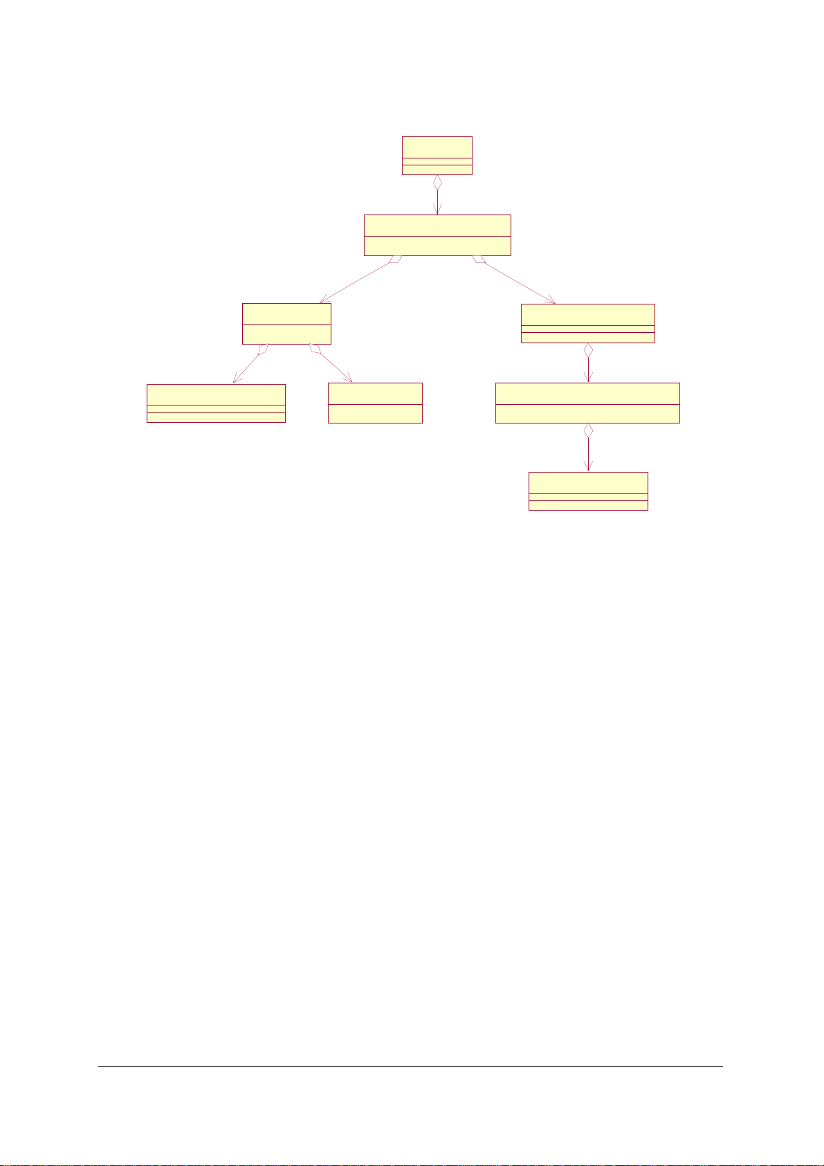
The management model is fully defined in [REF_110]. An example class tree for the
1800MHz EDGE/AMR BTS is given below.
nanoBTS Product Description Software Specification
© ip.access Ltd Page 19
Page 25
bss_001
0..2000..200
btsSiteManager_004
btsNse_002
1..11..1
gprsCellEgprs_004
0..10..1
btsNsvc_001
1..21..2
basebandTransceiver_004
1..11..1
btsEdge1800_005
1..41..4
8..88..8
channelAmr_002
Figure 7 - 1800MHz, EDGE/AMR nanoBTS management model
5.5.4 Code Download
The BTS supports code download by using the software download function of the
BtsInstaller tool (see [INST_300]).
The BTS examines the header of the downloaded file to determine if the BTS hardware is
compatible with the SW. If any part of the code download is incompatible with the
hardware, then the code download is NACK’d and the transfer is aborted, without affecting
the running or the stored code.
For DHCP triggered TFTP, once the code has been successfully downloaded and the
TFTP is complete, then the BTS shall set an internal flag (not set / get able from the
outside world) to "disable DHCP triggered TFTP on reboot" in EEPROM. The BTS shall
change the "Default" index to the index that it has just successfully downloaded. Then the
BTS should reset itself. Once reset the BTS shall clear this flag (so that on the next reboot
a DHCP triggered TFTP download is permitted) and begin executing this code.
If a code download fails or is aborted for any reason, then a Failure Event Report is sent to
the management system.
nanoBTS Product Description Software Specification
© ip.access Ltd Page 20
Page 26

5.6 Air Interface
5.6.1 Channel Combinations
The valid channel combinations on a "standalone" nanoBTS or on the Site Master TRX of
a Multi-TRX configuration are:
Timeslot Channel Types Allowed Restrictions
TS0 Full BCCH
Combined BCCH
Combined BCCH with CBCH
TS1 SDCCH/8
SDCCH/8 with CBCH Only if TS0 is Full BCCH
TCH/F, TCH/H Requires 165 BTS with SR3 software
Dynamic TCH/F, TCH/H Requires 165 BTS with SR3 software
Dynamic PDCH/TCH
PDCH
TS2-7 TCH/F, TCH/H TCH/H requires 165 BTS with SR3 software
Dynamic PDCH/TCH
PDCH
The valid channel combinations on a Slave TRX of a Multi-TRX configuration are:
Timeslot Channel Types Allowed Restrictions
TS0 and
TS2-7
TCH/F, TCH/H
Dynamic TCH/F, TCH/H
TCH/H and Dynamic TCH/H requires 165
BTS with SR3 software
TS1 SDCCH/8 Must be without CBCH
TCH/F, TCH/H TCH/H requires 165 BTS with SR3 software
Dynamic TCH/F, TCH/H Requires 165 BTS with SR3 software
The BTS supports different Training Sequence Codes (TSC) on each channel.
5.6.2 Power Control and Handover
The BTS supports MS Power Control algorithm according to [GSM05.08] annex A.
The BTS supports "Non Synchronised" handover.
The BTS does not support "Synchronised" handover of any variant.
The BTS performs Measurement Pre-processing to determine when a handover should
occur and provides an ordered candidate list of Neighbour Cells to handover to (according
to GSM 05.08 Annex A). The algorithm may be configured via "Measurement Pre-Process
defaults" message (see section 5.14.2) in which case it is enabled. Configuration is BSC
specific. Handovers can occur between different bands (e.g. 900MHz and 1800MHz).
The BTS sends RfResourceInds to monitor the background RF received power on unused
timeslots.
nanoBTS Product Description Software Specification
© ip.access Ltd Page 21
Page 27

The BTS supports the "Directed Retry" procedure on a particular MS to produce a list of
candidate NCELLs that it can be handed over to.
5.6.3 Cell Broadcast
The BTS supports the "SMS-CB Default" message
The BTS supports the "SMS-CB Normal" message
The BTS does not support the "SMS-CB Scheduled" message
The BTS does not support the CBCH Flow control. The BTS sends an 08.58 ErrorInd upon
receipt and throws a warning level FER (see section 5.7).
5.6.4 CCCH
The BTS supports Paging Re-organise and shall autonomously detect this by monitoring
the System Information.
CCCH load management is supported via configurable Load Indication Period and
Threshold attributes.
RACH load management is not supported.
Paging messages are repeated with configurable "Repeat Count" and "Repeat Period".
Paging repeats do not automatically terminate on receipt of the SABM.
5.6.5 System Information
The BTS transmits System Information (SI) messages as part of the BCCH channel (as
defined in GSM 04.08 and 05.02).
The BTS supports SI 1, 2, 2bis, 2ter, 3, 4, 5, 5bis, 5ter, 6 (on SACCH), 7, 8, 13
The BTS does not support SI 9, 10, 16, 17.
All other System Information messages are not supported.
5.7 Error Handling
All software errors generate a "Failure Event Report" (FER) with manufacturer specific
"Probable Cause". SW warnings include module and line number in the "Additional Text"
IE’s.
The BTS supports SNMP traps for all errors. Within the SNMP MIB there will be an entry of
"last reported error".
There is a HW watchdog shall reset the system in case of unhandled errors.
Fatal Software errors store the error code in memory, and send a FER after reboot.
The BTS keeps a log of the last 10 SW and the last 10 HW errors in EEPROM including
time and date of occurrence.
The BTS supports the GSM 12.21 (Version 5) "Request Outstanding Errors" procedure so
that a BSC can list the state of all possible faults.
The BTS detects the loss of Ethernet connection by sending "keep-alive pings".
nanoBTS Product Description Software Specification
© ip.access Ltd Page 22
Page 28

5.8 System Monitoring
The BTS monitors the Radio Synthesiser OPLL to ensure that it is transmitting on
frequency. This will be done once per GSM frame. If an error is detected then the BTS will
autonomously attempt to relock the OPLL. If the synthesiser does re-lock then a warning
level FER shall be sent and immediately ceased. If the synthesiser fails to lock then a
critical level FER on the radio carrier object is sent.
The BTS monitors the transmitter Power Amplifier OOL signal once per GSM Frame. If the
BTS detects that the PA OOL signal is in error then the BTS shall send a major failure FER
for the radio carrier object (the BTS does not reboot).
The BTS monitors its internal temperature. This is represented as a percentage of the
nominal operating range. If the reading exceeds the "Temperature Alarm Thresholds" that
are set in EEPROM then a FER shall be sent. It shall also send an SNMP trap. The
default alarm thresholds are 0% and 100%. The percentages can go below 0% and are
indicated as a signed number between –128% and +127%.
The BTS monitors its Input Voltage. If the result exceeds the "Voltage Alarm thresholds"
then the BTS shall send an FER. It shall also send an SNMP trap. The default alarm
thresholds are 0% and 100%.
5.8.1 SNMP Specific Features
The BTS supports SNMP v2C (Community-based) only.
The BTS supports the
• SMIv2 "Interfaces" MIB (see SMIv2 - Interfaces MIB - RFC 2233)
• SMIv2 "IP" MIB (see SMIv2 - IP MIB (IPv4) - RFC 2011)
• SMIv2 "TCP" MIB (see SMIv2 - TCP MIB - RFC 2012)
• SMIv2 "UDP" MIB (see SMIv2 - UDP MIB - RFC 2013)
• "Ethernet Interface MIB" – iso88023-csmacd group (see SNMP Ethernet Interface
(EtherLike) MIB – RFC 1643)
• SNMPv2 MIB. (see SMIv2 – SNMPv2 MIB – RFC 1907) with System group, SNMP
group and MIB Objects group.
The BTS does not support SNMP "Sets". These shall be responded with the appropriate
"SetResponse".
The BTS supports SNMP "Get", Get Next and "Get Bulk" on the supported MIBS
The BTS supports SNMP "Traps" on the supported MIBS.
The BTS supports SNMP enterprise "Traps" on all 12.21 failure event reports (except
"Warning" or "Logged Warning" level failures) as the "last reported error" in the
ip.access.v1 MIB. If the trap address is not NULL then a trap should be sent to the SNMP
management agent.
The BTS supports setting of the SNMP "Community string" EEPROM parameter via 12.21
extensions only.
The BTS supports setting of the SNMP "Community string IP address" (that shall be used
to limit SNMP gets by IP address) EEPROM parameter via 12.21 extensions only.
nanoBTS Product Description Software Specification
© ip.access Ltd Page 23
Page 29

The BTS supports setting of the SNMP "SysContact" EEPROM parameter via 12.21
extensions only.
The BTS supports setting of the SNMP "trap address" EEPROM parameter via 12.21
extensions only.
The SNMP "SysLocation" shall be derived from 12.21 "location" string stored in EEPROM.
Similarly the SNMP "SysName" shall be derived from the 12.21 "name" string stored in
EEPROM.
The BTS supports the "ipaccess.v1" enterprise MIB that includes:
• description (of hardware)
• partNumber (hardware part number)
• partNumber (software part numbers and versions)
• serial number
• date and time of manufacture
• date and time of calibration
• input voltage (Volts)
• current draw (Amps)
• temperature (˚C) – signed number
• power (Watts)
• array of alarm states (for "input voltage", "current draw", "temperature" and "power")
• last reported error
5.8.2 LED States
It is possible to Disable the LED output (using 12.21 Set NV Attributes), however for some
critical errors and for visual indication of on-site procedures (e.g. factory reset of database)
the LED will still come on (see below).
In general, the LED states have a concept of precedence. Higher priority LED states take
precedence over lower priority states.
With LED flag = ENABLED:
Table 1 - LED states when LED Enabled
State Pattern When Precedence
LED_SELF_TEST_FAILURE
LED_UNSPECIFIED_FAILURE
Red
Steady
Red
Steady
In boot or
application code
when a power on
self test fails.
On s/w fatal
errors.
1
(High)
2
LED_NO_ETHERNET
nanoBTS Product Description Software Specification
© ip.access Ltd Page 24
Orange
Slow Flash
Ethernet
disconnected.
3
Page 30

LED_DOWNLOADING_CODE
Orange
Fast Flash
Code download
procedure is in
progress.
4
LED_ESTABLISHING_OML
LED_FACTORY_RESET
LED_SELF_TEST
LED_NWL_TEST
LED_LOCKED
Orange
Slow Blink
Red
Fast Blink
Orange
Steady
Green
Fast Flash
Green
Slow Flash
OML not yet
established (via
primary or
secondary OML
port) but is needed
in order for the
BTS to become
operational.
Dongle detected
at start up and the
factory defaults
have been
applied.
From power on
until end of
backhaul power
on self-test
OML established,
NWL test in
progress
OML established,
but an MO is
locked that will
prevent C0 being
transmitted.
5
6
7
8
9
LED_OPERATIONAL
Green
Steady
Default condition if
none of the above
10
(Low)
apply.
Note: When the nanoBTS is operational, it should continue to operate even if the OML
connection is lost, and the LED should continue to show steady green.
With LED flag = DISABLED:
Table 2 - LED states when LED Disabled
State Pattern When Precedence
LED_SELF_TEST_FAILURE
Red
Steady
In boot or
application code
1
(High)
when a power on
2
3
LED_UNSPECIFIED_FAILURE
Red
Steady
LED_NO_ETHERNET Off
self test fails.
On s/w fatal
errors.
Ethernet
disconnected.
nanoBTS Product Description Software Specification
© ip.access Ltd Page 25
Page 31

LED_DOWNLOADING_CODE Off
Code download
procedure is in
progress.
4
LED_ESTABLISHING_OML Off
LED_FACTORY_RESET
Red
Fast Blink
LED_SELF_TEST Off
LED_NWL_TEST Off
LED_LOCKED Off
LED_OPERATIONAL Off
From power on
until OML
established.
Dongle detected
at start up and the
factory defaults
have been
applied.
From power on
until end of
backhaul power
on self-test.
OML established,
NWL test in
progress.
OML established,
but an MO is
locked that will
prevent C0 being
transmitted.
Default condition if
none of the above
apply.
5
6
7
8
9
10
(Low)
The non-steady LED states are defined as:
Table 3 - LED flash and blink timings
Slow Flash 1.0s 1.0s
Fast Flash 0.5s 0.5s
Slow Blink 1.9s 0.1s
Fast Blink 0.3s 0.1s
Mark Space
nanoBTS Product Description Software Specification
© ip.access Ltd Page 26
Page 32

5.9 Traffic
5.9.1 Channel Types
The BTS supports the transport of
• Full Rate (FR)
• Enhanced Full Rate (EFR) GSM speech.
• AMR full- and half-rate speech (requires 165 BTS with SR3 software)
• BS20 (14.4k) single slot circuit switched data.
• BS21-26 (up to 9600) single slot circuit switched data
• BS61 and BS81 speech-then-data and alternate-speech-and-data.
The BTS does not perform any transcoding, but it does perform rate adaption for circuit
switched calls to deliver all CSD bearers in V.110 frame format, for compatibility with the
ip.access circuitBSC.
5.9.2 Encryption
The BTS supports A5/1 and A5/2 encryption, as well as no-encryption. Some units may
not be supplied with encryption in the software load, because of export restrictions or other
reason. The BTS rejects attempts to set up channels with encryption scheme not
supported in a particular software build.
5.9.3 Traffic Frame Formats
The BTS supports the carrying of raw 64kb/s payload for circuit switched data (as PCM
may be carried by IETF standards).
The BTS supports the IETF standard frame format of RTP for Speech calls on (for AMR
see RFC3267, and RFC3551 for FR/EFR).
The BTS supports a nanoGSM-proprietary RTP payload format for multiplexed payloads
(to minimise bandwidth).
5.10 Performance
The BTS is rated to support a loading of 600 BHCA with <1% error rate of call set-up
failures, directed retries, handovers and location updates due to internal performance
constraints of the BTS.
nanoBTS Product Description Software Specification
© ip.access Ltd Page 27
Page 33
5.11 Peripherals
ILLEGAL
DEFAULTED
MODIFIED
initialise
modify
5.11.1 Backhaul
5.11.1.1 Miscellaneous
The BTS contains a Fast Ethernet Controller IC (FEC) with 10/100 mbps auto-negotiation
(auto-negotiation occurs without needing to reboot).
5.11.1.2 EEPROM Storage
The EEPROM structure is protected against bit error using a CRC check mechanism.
5.12 NV Configuration
5.12.1 Parameters
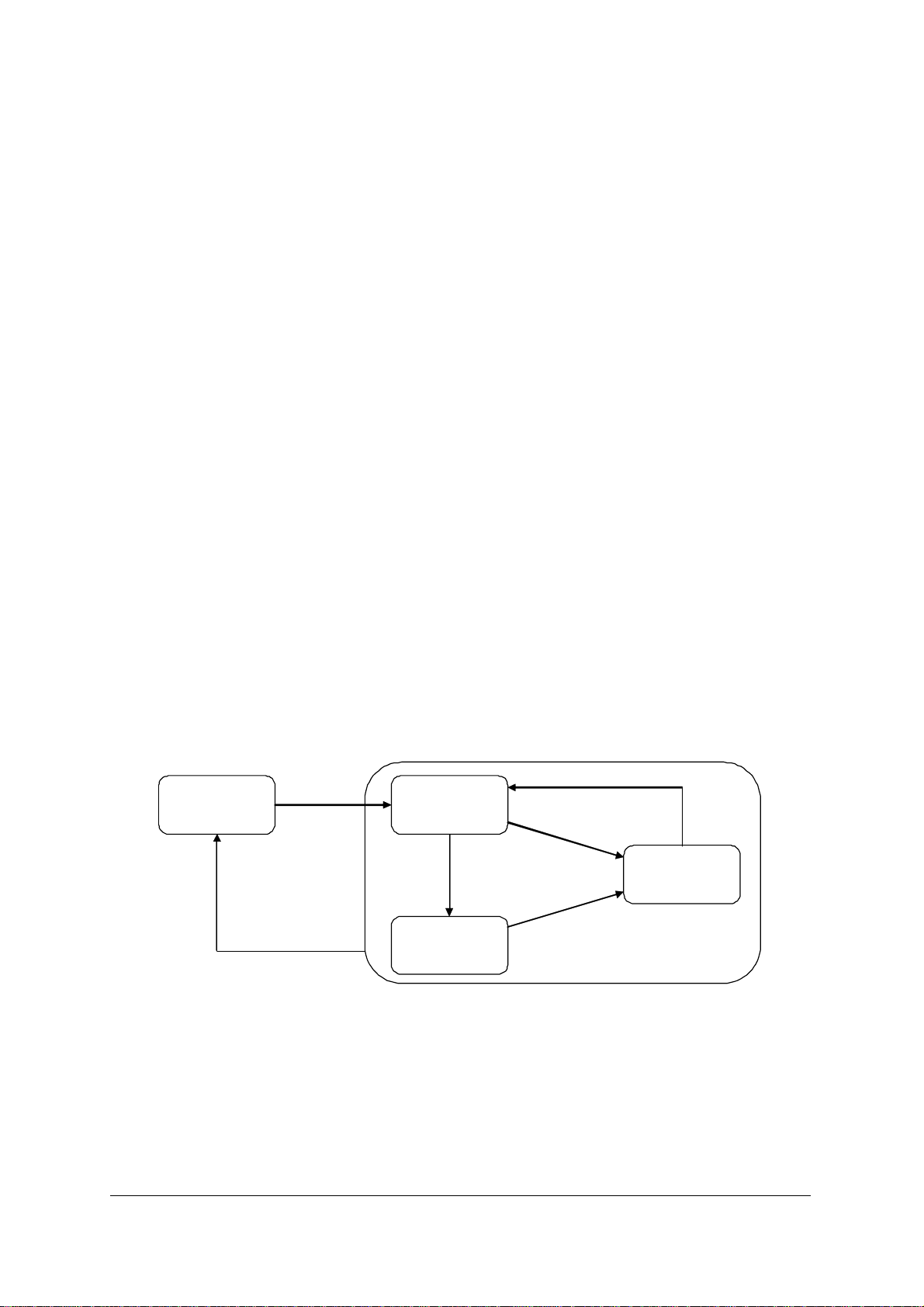
The NV management state model for each parameter is as shown in Figure 8. All
attributes are initially in the "illegal" state. This means that the store is completely invalid. If
the store is "illegal" when the software starts up then its structure is written and all
attributes are "defaulted".
Type 1 attributes will be "initialised" and cannot be "modified", for example the MAC
address. Type 2 attributes can be "modified", for example whether DHCP is enabled. To
prevent changing read-only "initialised" values, if the OEMid value is non-null (has been
"initialised") then write access to Type 1 attributes is denied. Given this model, the factory
code requirements can be achieved using a single software image and a single defined
use of the dongle.
default
corruption
INITIALISED
reset (if not retained)
modify (if retained)
Figure 8 - NV configuration model
All attributes listed in Table 4 with "Initialised? == Y" are assumed to be type 1 attributes
and cannot be overridden once OEMid has been set in the factory (except for the case of
"OCXO DAC Value" which can be adjusted using the SetNVAttributes message or as a
result of a frequency synchronisation test using NWL). For returned units in the factory, the
OemID can be overridden with a special command (see FAT_017).
nanoBTS Product Description Software Specification
© ip.access Ltd Page 28
Page 34

All other attributes are type 2. Those marked "Retained? == Y" are not reset to factory
defaults by insertion of the dongle.
If the EEPROM is deemed to be corrupt then the BTS attempts to send a FER as soon as
it connects (or is connected to) an OMC (see section 5.7). It shall also set the base-band
transceiver managed objects to "Disabled, Failed". The LED state should also be set to
"LED_FACTORY_RESET".
Note: Not all NV parameters are available for use by end-customers. Some are
reserved for factory or other internal ip.access use.
Note: The presence of an NV flag does not indicate support of a feature of the same
name.
Table 4 - NV Attributes
Attribute Default Value Initialised? Retained?
MAC Address 00:02:95:00:00:00
PCB Assembly Part
"108_029"
Number
PCB Assembly Issue "X"
HW/SW
0x02
Compatibility
CEM Id 0xFF
CEM Serial Number " "
IPA Serial Number " "
OEM Id 0xFF
Date and Time of
01/01/1900 00:00:00
Manufacture
Date and Time of
01/01/1900 00:00:00
Calibration
OCXO Slope 0x0000
Y N/A
Y N/A
Y N/A
Y N/A
Y N/A
Y N/A
Y N/A
Y N/A
Y N/A
Y N/A
Y N/A
Max OCXO Current
1000
Y N/A
(mA)
Default Gateway 0.0.0.0
Subnet mask 0.0.0.0
IP Address 0.0.0.0
Primary OML Link IP
0.0.0.0
N N
N N
N N
N N
Address
Primary OML Port 0
nanoBTS Product Description Software Specification
© ip.access Ltd Page 29
N N
Page 35

Secondary OML Link
IP Address
0.0.0.0
N N
Secondary OML Port 0
Flags 1 – Static
FALSE
Interface IP Config
Flags 1 – Static IP
FALSE
Gateway Config
Flags 1 – Static
FALSE
Primary OML Config
Flags 1 – Dhcp TRUE
Flags 1 – LED TRUE
Flags 1 – Alarm
TRUE
Thresholds NV
Flags 2 – Secondary
TRUE
OML Enable
Flags 2 –
FALSE
Diagnostics Enable
Flags 2 – CLI Enable FALSE
Flags 2 – HTTP
FALSE
Enable
N N
N N
N N
N N
N N
N N
N N
N N
N N
N N
N N
Flags 2 – POST
FALSE
Enable
Flags 2 – SNMP
TRUE
Enable
OCXO DAC Value 0x0000
Input Supply Voltage
100
Thresh Max Percent
Input Supply Voltage
0
Thresh Min Percent
BTS internal
100
Temperature Max
Percent
BTS internal
0
Temperature Min
Percent
Input Supply Current
100
Thresh Max Percent
Input Supply Current
0
Thresh Min Percent
Input Supply Power
100
Thresh Max Percent
N N
N N
Y Y
N N
N N
N N
N N
N N
N N
N N
nanoBTS Product Description Software Specification
© ip.access Ltd Page 30
Page 36

Input Supply Power
Thresh Min Percent
0
N N
BTS Location " "
BTS Name " "
Site Id 0xFFFF
BTS Id 0xFF
TRX Id 0xFF
In Service Time 0
Primary OML
0.0.0.0
fallback address
Primary OML
0
fallback port
SNMP community
"public"
string
SNMP Trap Address 0.0.0.0
SNMP Trap Port 0
N N
N N
N N
N N
N N
N Y
N N
N N
N N
N N
N N
SNMP Manager
0.0.0.0
N N
Address
SNMP System
"Not Known"
N N
Contact
Note: "OEM Id" is defaulted with its null value 0xFF.
Note: "Date and Time of Calibration" is re-initialised whenever a full calibration is
performed.
Note: "Subnet mask" is defaulted with its null value – if IP Address is configured and
subnet mask is null then use a class mask appropriate for this address.
Note: "Primary OML Link IP Address" is initialised with its null value. The software
must prevent attempts to use this address (NULL value) when connecting to
servers.
Note: "Primary OML IP Port" is initialised with its null value. When booting with this null
value, the software will choose an appropriate vendor specific value.
Note: "Flags 1 – Dhcp" is not directly settable. If any of the three static IP config flags
(interface, gateway or OML) are false then this is true, otherwise it is false.
Note: "Flags 1 – Alarm Thresholds NV" is not directly settable. If any of the voltage,
current, power or temperature thresholds are set, then this is true, otherwise it is
false.
Note: "BTS Name" is defaulted with its null value. If the software detects this null value
then it uses the value "nbts-" concatenated with the "-" separated MAC address.
nanoBTS Product Description Software Specification
© ip.access Ltd Page 31
Page 37

5.12.2 TRX Controlled Parameters
Attribute Default Value Notes
TRX database schema
TX Power ramps 13 levels, 32 x UInt16
TX Scale factors 13 levels, UInt16 for each level
TX Frequency compensation 12 ARFCN’s, UInt16 for each ARFCN
TX DC Offsets 0x0, 0x0 2 x SInt16
RXGainControlNormal
(i.e. uplink receiver)
RXGainControNWL
(i.e. downlink receiver)
RxAccurateGainNormal
(i.e. uplink receiver)
RxAccurateGainNWL
(i.e. downlink receiver)
RxFreqCompNormal
26 AGC steps, UInt16 for each step
26 AGC steps, UInt16 for each step
26 AGC steps, UInt16 for each step
26 AGC steps, UInt16 for each step
12 ARFCN’s, SInt16 for each ARFCN
(i.e. uplink receiver)
RxFreqCompNWL
12 ARFCN’s, SInt16 for each ARFCN
(i.e. downlink receiver)
RxDC Offsets 0x0, 0x0 2 x SInt16
5.13 Operations
5.13.1 Network Listen
The BTS supports
• the "Channel Usage" test to determine received power on requested ARFCNs.
• the "BCCH Channel Usage" test to determine if the channel contains a FCH and
SCH channel. It reports report the power level, BSIC, frame and sub-frame offset if a
BCCH is detected.
• the "BCCH Info" test. It decodes SI1 to determine the CA list and SI3 to determine
the CGI (Cell Global Identity). It captures SI2, SI2-bis, SI2-ter and sends them as
entire SI messages in the result. The test may take up to 35 seconds to pick up all of
the system information types off-air.
• the "Frequency Synchronisation" test to measure the frequency offset of other
basestations with respect to its own OCXO setting. For each ARFCN it reports a
frequency quality metric and the offset in ppb’s. When the frequency error is such
that the BTS can measure a coarse frequency offset from the FCH, but cannot
decode the SCH (because the DSP equaliser cannot resolve the frequency offset) it
reports an error with a frequency quality of "0".
nanoBTS Product Description Software Specification
© ip.access Ltd Page 32
Page 38

• the "Beacon mode" test to enable other basestations to monitor it. This test is
configurable to set the BSIC, ARFCN and transmit power to be used. The test
continues until a "Stop Test" request is made. The transmitted BCCH information
marks the cell as "barred" for all access types.
NWL tests will take the BTS out of service for the duration of the test. The BTS will restart
service after the test is complete. A state change event report is generated at the
beginning and end of the test.
5.13.2 Normal Operation
After boot-up and POST (if enabled), the BTS attempts to connect to Primary OML (as
indicated in IP and Port number settings in database).
Once connection is established, it uses "heart-beat" connection message as defined in the
ip.access Abis Over IP specification to detect if connection has gone down.
The BTS starts up a second OML server (if enabled in NV Config flag F9). It uses the
second OML port specified in NV, or if this is NULL then assume a default of 3006. If the
second oml IP address field is not NULL then it should reject connections from IP
addresses that are not the same. SW activation can occur on either primary or secondary
OML.
On loss of the second OML client the BTS does not reboot. Interrupted procedures are
terminated and do not take effect.
Once the BTS has established any OML connection it performs a "SW Activation Request"
for the Site Object.
Once the BTS has performed the "SW Activation" for the Site object it performs a "SW
Activation Request" for the Baseband Transceiver Object.
Once the BTS has performed the "SW Activation" for the Baseband Transceiver object it
will perform a "SW Activation Request" for the BTS object.
Once the BTS has performed the "SW Activation" for the BTS object it performs a "SW
Activation Request" for the Radio Carrier Object.
The BTS shall send "State Change Event Report" messages at the appropriate times (as
defined in GSM 12.21) whenever the managed object state changes.
5.13.2.1 SW Activation Procedure
The HW Configuration attribute in the SW Activate Request is the same for all objects, and
is the same as would be obtained by sending a Get Attributes message to an object.
The SW Configuration attribute includes at least one SW Description for each type of
image that it is dependent on, excluding boot code.
Note: The boot code has already finished executing by the time software activation
occurs, so there is no need to activate it.
If, when an object sends a SW Activate Request, a version of an image that it depends on
has already been activated, it only includes that version’s SW Description, otherwise it
includes a SW Description for each version of the image that is available for activation.
If the same software version is in both banks, then both banks shall be reported where
applicable (see above).
nanoBTS Product Description Software Specification
© ip.access Ltd Page 33
Page 39

Note that the value of the SW Configuration attribute in a SW Activate Request message
sent by an object is therefore not the same as that of the SW Configuration attribute
obtained by sending a Get Attributes message to the object. i.e. the SW Configuration
Attribute reported as a response to the "GetAttributes" message includes the "Boot
application"; the "Boot application" is not included in "SW Activate Request" messages.
Where a SW Activate Request contains more than one SW Description for a given image
type, the first one is the "default" image. An image can be selected (eg. under user control)
as the default image by sending a manufacturer-defined operations and maintenance
message, "Set Default SW" to the nanoBTS.
Note: The term "Boot" in "Set Default SW" does not refer to the nanoBTS’s boot code
image, it refers to the (backhaul and TRX) software that the nanoBTS should run
by default the next time it is rebooted.
The BTS expects to receive a SW Activate message in response to each SW Activate
Request that it sends. The SW Activate message may contain 0, 1, or more SW
Descriptions – and each of these must have been present in the corresponding SW
Activate Request message. If it contains no SW Descriptions, the object to which it is sent
will default to activating the most sensible default set of software. If it contains more than
one SW Description, they should be such that they can all be activated (for example, there
should not be more than one version for a given File Id).
Each managed object as defined in GSM 12.21 (Site Manager, BTS, Baseband
Transceiver, Radio Carrier, and Channel) has a SW Configuration attribute, which is a list
of one or more SW Description attributes. In the nanoBTS, each object’s SW Configuration
will contain a SW Description for each version of each of the images on which the object
depends. (An object depends on a software image if the physical item that it represents
requires the image to be executed before it can provide any service.)
Each 12.21 managed object has a HW Configuration attribute, which is a list of one or
more HW Description attributes. In the case of the nanoBTS, each object’s HW
Configuration attribute will contain exactly one HW Description, which will have the same
value for all objects. This HW Description relates to the PCB assembly inside the
nanoBTS.
The BTS’s Site Manager object sends a SW Activate Request containing a SW Description
for each backhaul software image that is present. The first (and perhaps only) of these
refers to the backhaul software that is currently running.
The BTS expects the BSC to send a SW Activate message containing either no SW
Descriptions, or one SW Description. If there is no SW Description or there is one and it
refers to the version of backhaul software that the BTS is currently executing, that is
marked as having been activated, and the procedure continues. If there is one SW
Description and it refers to the version of backhaul software in the other bank, the BTS
marks that version as the default, and restarts itself. On restart, the BTS executes the
version marked as the default, and repeats the software activation procedure. Note that it
shall not send anything else to indicate that it had to reboot (such as a FER). This time, the
Site Manager’s SW Activate Request message will include the SW Description for the
backhaul software that is now executing before the SW Description for the version that it
was previously executing.
nanoBTS Product Description Software Specification
© ip.access Ltd Page 34
Page 40

The BTS’s Baseband Transceiver object sends a SW Activate Request containing a SW
Description for the backhaul software image that was activated on the Site Manager
object, plus a SW Description for each TRX software image that is present. The BTS
expects the BSC to send a SW Activate message, which may contain no, one, or two, SW
Descriptions. If there is no SW Description, the nanoBTS will activate the "default" TRX
device software. If there is a SW Description for the backhaul, it must match that which
was sent in the SW Activate Request. If there is a SW Description for the TRX software,
the nanoBTS will load the specified version onto the TRX device and execute it.
The nanoBTS’s BTS object sends a SW Activate Request containing a SW Description for
the backhaul software image that was activated on the Site Manager object. The BSC
should send a SW Activate message to the BTS object containing either no SW
Descriptions, or the one SW Description that was in the SW Activate Request. In either
case the procedure continues. If the BSC sends a SW Activate message in response that
does not match any of its SW Descriptions then the BTS shall N’ACK the message.
The BTS’s Radio Carrier object sends a SW Activate Request containing one SW
Description for the backhaul software image that was activated on the Site Manager object
and one for the TRX software that was activated on the Baseband Transceiver object. The
BSC should send a SW Activate message to the BTS object containing either no SW
Descriptions, or one or both of the SW Descriptions that were in the SW Activate Request.
In either case, this is the end of the software activation procedure, and the other
procedures associated with starting up the BTS can be carried out.
5.14 Abis Interface (ABIS)
The BTS conforms to the ip.access Abis Over IP specification.
5.14.1 Operations and Maintenance Signalling Messages
The BTS supports Abis messages according to the ip.access Abis Over IP specification
and as clarified below on both primary and secondary OML links.
The BTS initiates the "Primary OML Establishment" procedure to the defined
"primaryomlipport" parameter in EEPROM configuration. If this is set to the NULL value
(see section 5.12) then the BTS shall use the vendor specific port number as defined in the
software build (IPA BSC = 3002).
The BTS supports the "Connect IP Signalling" message according to the ip.access Abis
Over IP specification.
The BTS supports the "Set Default SW" message according to the ip.access Abis Over IP
specification. This has the effect of adjusting the EEPROM parameter so that on the next
reboot the BTS will boot the specified Backhaul Index (see section 5.4.1). It will also use
the "default" set indexes (for Backhaul and TRX) as its first preference offered to the BSC
in the SW Activation procedures.
On receipt of new configuration the BTS will immediately use the configuration for the
NVConfig Flags F7-F9. Note that in the case of F9 (Second OML Enable) that this does
not disconnect current connections, but stops new connections.
The BTS will adjust the Frequency control immediately upon receipt of new configuration
of the "Frequency Control" IE.
nanoBTS Product Description Software Specification
© ip.access Ltd Page 35
Page 41

The BTS does not immediately use the new Primary OML or Secondary OML
Configuration if a connection has already been established. It shall use the configuration
for all new connections.
The BTS does not immediately action receipt of configuration of new IP Configuration
(either from the "IP Interface Config" or "IP Gateway Config"). A reboot is always required.
The BTS immediately actions receipt of configuration of new BTS Location.
The BTS does not immediately use new Unit Id configuration (BTSid and TRXid). A reboot
is always required. For single TRX configuration, the TrxId is always be 0.
The BTS supports setting of the "Name" field.
The BTS supports the extension to the "SetBTSAttribute" message for paging
configuration. Note that the defaults are hard coded and cannot be adjusted in NV
configuration.
The BTS supports the Set Alarm Thresholds with the behaviour as defined in the ip.access
Abis Over IP specification. Note that the behaviour depends on the NVConfig flag F8
("SetAlarmThresholds").
The BTS supports the "Perform test" message for starting NWL tests according to the
ip.access Abis Over IP specification.
The BTS supports the "Get Attribute" message as defined in the ip.access Abis Over IP
specification and not as per GSM 12.21 V5.0.0.
The BTS supports the "Reinitialise" message.
5.14.2 RSL Signalling Messages
The BTS uses the "Measurement Pre-processing Defaults" messages for configuration of
the Measurement Pre-processing algorithm (according to the ip.access Abis Over IP
specification). The BTS should accept this message at any time and apply new defaults for
new dedicated connections. The BTS or any sub-object does not need to be locked for this
to take effect.
5.14.3 User Traffic Messages
The BTS supports RTP Traffic format as defined in the ip.access Abis Over IP
specification.
The BTS does not support the Traffic Frame Synchronisation Procedure.
5.14.4 Channel Control Messages
The BTS supports the "Heartbeat" procedure according to the ip.access Abis Over IP
specification. The BTS requires the Identity Request Message over TCP or UDP. The
BTS shall respond to a UDP message to the well-known "second omlipport" number
(3006).
Upon heartbeat failure of OML, the BTS shall try to carry on if already operating, keep
trying to reopen the connection. Messages should be discarded as required to avoid
overflow (e.g. whenever connect returns a failure, discard any queue and immediately
retry, if too many things queue whilst awaiting connection, discard as required).
Upon heartbeat failure of RSL, the BTS shall disable the relevant TRX, dropping calls and
clearing up as required, (it should act as if locked and then immediately unlocked again).
nanoBTS Product Description Software Specification
© ip.access Ltd Page 36
Page 42

Keep trying to connect, send an alarm to the operations and maintenance, resume normal
operations as soon as link is restored.
5.15 GPRS Feature Support
The BTS supports
• Gb over IP, with NS frames being transported over UDP/IP.
• Mobiles up to multislot class 10.
• All coding schemes, CS1 through CS4, with link adaptation. MCS1 through MCS9 is
also supported on the 165 BTS with SR3.0 or later software
• Air interface timeslots may be configured statically for GPRS or dynamically for
GPRS. In the latter case the timeslots may be used as either TCH or GPRS
according to traffic patterns
• NC mode 0.
• MAC dynamic uplink allocation
• Circuit mode paging during GPRS transfer
• MAC 2 phase access
nanoBTS Product Description Software Specification
© ip.access Ltd Page 37
Page 43
6 SOFTWARE IMPLEMENTATION (INFORMATIVE)
OCXO
RX TX
PHY
6.1 139/140 Platform
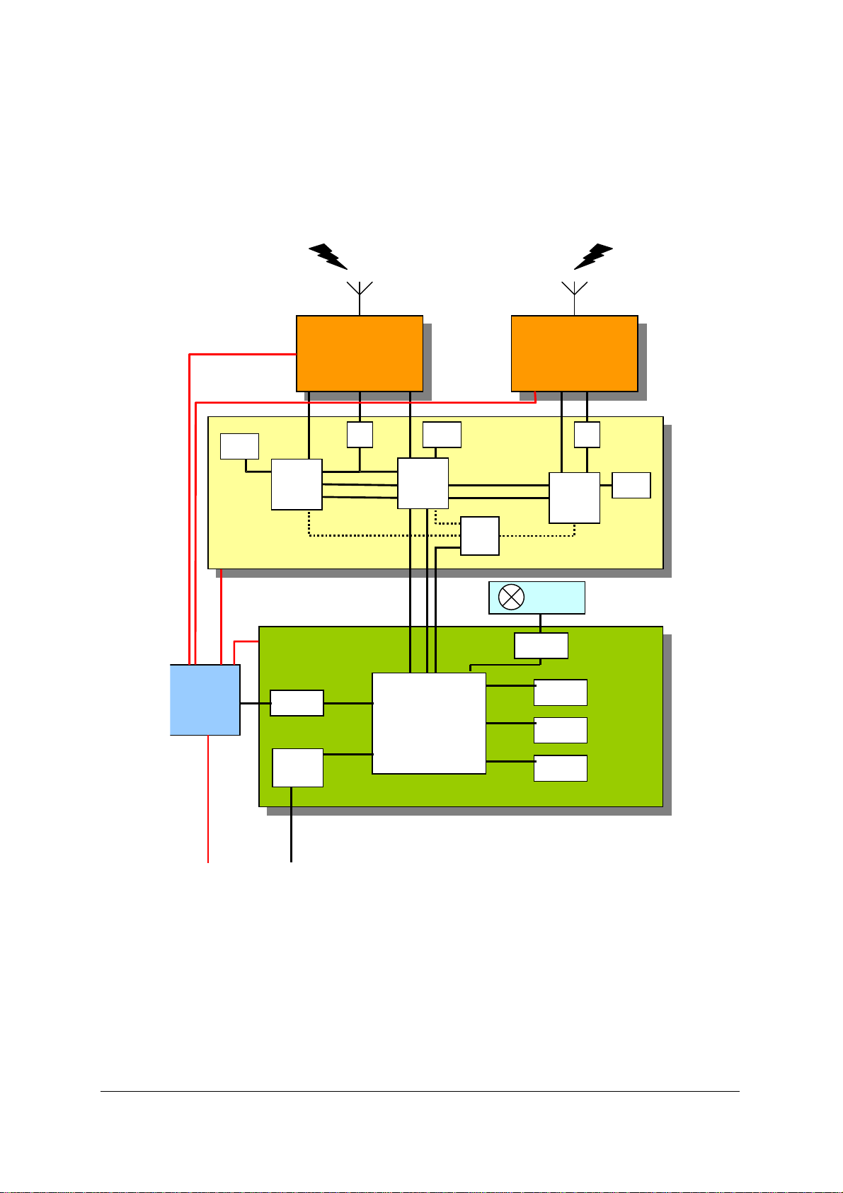
The hardware platform for the BTS is shown in Error! Reference source not found..
SRAM
TRX Device
PSU
48v
AGC
ULS
Backhaul
ADC
VBC
Reset
Async
SRAM
AGC
SYNTH
ULM
Power PC
HDLC
FPGA
Reset
Async
DAC
SDRAM
FLASH
EEPROM
SYNTH
VBC
DLP
SRAM
Ethernet
Figure 9 - Internal architecture of the 139/140 nanoBTS
It consists of three handset baseband devices (ADmsp430), a general purpose
communications processor (MPC855T), and an FPGA based interprocessor
communications buffer and synchronisation channel.
The ADmsp430 device consists of an ARM7 microcontroller, a Viterbi coprocessor, a
ciphering engine, timing and control logic (the TCU), and an Analog Devices 21B series
DSP device. The ARM7 runs AMX with application code written in ANSI C. The DSP runs
native assembler.
nanoBTS Product Description Software Implementation (informative)
© ip.access Ltd Page 38
Page 44

The MPC855T device runs the Nucleus operating system which includes TCP, UDP, IP,
ICMP, SNMP, and all MPC855T device drivers (as part of the Board Support Package).
Other application code is developed internally by ip.access, written in ANSI C.
The FPGA is responsible for managing interprocessor communications buffers. An HDLC
controller is implemented within it, which communicates directly to a similar sub-system in
the MPC855T.
The FPGA also implements GSM frame level synchronisation between the three
ADmsp430 devices.
6.2 Functional Partitioning
Broadly speaking, the GSM air interface functionality is managed by the three ADmsp430
devices, designated the ULM (uplink master), ULS (uplink slave) and DLP (downlink
processor). These are collectively known as the TRX. The Ethernet interface is managed
by the MPC855T, designed the BH (backhaul) processor.
The major functional elements within the nanoBTS are partitioned as follows
Function and sub-function Processor
GSM L1 Receive, including
soft-decision equalisation,
Even slots ULM
Odd slots ULS
de-interleave, channel
decoding and deciphering
GSM L1 transmit, including
All slots DLP
ciphering, channel coding,
interleave
GSM L2 processing,
DLP
including BCCH scheduling
GPRS PCU RLC/MAC BH
GPRS L1 TRX
GPRS Gb BSSGP and NS/IP BH
Operations and
Management Link (OML)
Processing
Abis/IP messages terminate
in the BH and generate
device driver calls as
BH
required
Radio Signalling Link (RSL)
Processing
RSL (GSM8.58) messages BH
Embedded GSM4.08
messages
TRX (for onward
transmission to MS)
Non-volatile storage BH
Code download
BH
management
IP stack and applications
DHCP, ICMP, TCP, RTP,
BH
RTCP, UDP
nanoBTS Product Description Software Implementation (informative)
© ip.access Ltd Page 39
Page 45

6.3 Interprocessor Communications
Secure communications within the nanoBTS are implemented as follows
BH to TRX
HDLC framing including checksum generation and checking
performed in MPC855T and FPGA
Intra-TRX (GSM L2) Messages carried and routed through the FPGA
ARM7 to DSP Dual-port memory interface
ARM7 to Synthesiser
DMA
programming registers
6.4 Process Scheduling
For software tasks running on the ARM7 and MPC855T cores, software processes are
scheduled either
• Asynchronously by the OS running on that processor, or
• Synchronously from interrupts generated by the underlying hardware devices or DSP
Software tasks running on the DSP are scheduled synchronously and deterministically
using interrupts generated by the TCU. DSP tasks are divided into frame-based and
block-based tasks. Frame based tasks have the highest priority, and include
• Burst data read and write
• Modulation and demodulation
• Equalisation, channel decode and deinterleave
• Receiver gain control
• Synthesiser programming
• Transmitter dynamic power control
Note that frame-based tasks occur every timeslot boundary.
nanoBTS Product Description Software Implementation (informative)
© ip.access Ltd Page 40
Page 46

Block based tasks execute every four frames, again, at the conclusion of each timeslot and
include
• L2 block transfer from DLP
• Channel coding and interleaving
• Viterbi decoding of soft-decision results from equaliser
• L2 block transfer to ULM/ULS
Block based tasks run at lower priority than frame based tasks, and are usually interrupted
by them.
6.5 Interprocess Communications and Synchronisation
(139/140 units)
Software processes within the ARM7 and MPC855T processors communicate with each
other exclusively using messages written to and read from OS maintained inter-process
message queues. Other methods of interprocess communications (such as semaphores
or shared memory) are not used.
The one exception to this rule is the communication between DSP and ARM. Software
running on the DSP core reads its data on interrupt generated by the TCU from dual-port
memory shared with the ARM.
nanoBTS Product Description Software Implementation (informative)
© ip.access Ltd Page 41
Page 47

7 DHCP
If EEPROM is corrupt the BTS will
assume a default MAC Address
within the manufacturer range.
START
MAC
N
Address in
valid
range ?
Validate MAC Address in EEPROM against
ip.access assigned Manufacturer's range.
Set Default MAC
Address
None/not
fixed
DHCP-
DISCOVER
Set Ts
SELECTING
NOTES
=====
1) All message transmissions have retransmission applied as required
in the RFCs.
2) nanoBTS has non-volatile storage for:
a) IP Address, Subnet & Static IP Interface IP config flag
b) Default Gateway & Static IP Gateway config flag. Previous versions
of this spec referred to a "Router" - this should be treated synomously
with "Gateway"
c) VSI (Primary & Secondary OML IP Address & Port, etc) & Static VSI
config flag (when clear VSI is requested), VCI is always sent
d) DHCP enable flag
3) The nanoBTS should only let the above config flags be set (i.e.
"static" or "disabled") if a corresponding value(s) is already known.
4) The optional restart REQUEST is not supported.
5) The Multicast Discovery method is not supported.
Y
Validate
stored Config
IP
address ?
VALIDATION RULES (in order):
============================
1) If IP Address not class A, B or C, clear IP Address
2) If IP address not set and 'static Interface IP Config' flag set, clear flag
3) If 'static IP Gateway Config' flag set but not 'static Interface IP Config'
flag, clear 'static IP Gateway Config' flag.
4) If Subnet Mask unset, use default mask for IP Address class (A, B or C)
5) If Default Gateway not in same subnet as IP address, clear 'static IP
Gateway Config' flag (if set) and Default Gateway IP address
Fixed
(static Interface IP Config
& IP address valid)
Set i/f IP Address
(with known or
default IP config)
AWAITING
GATEWAY
IP
Gateway
Config
known &
fixed ?
N
DHCP-
INFORM
Set Ti
CONFIG
Y
Request missing IP
Gateway Config & VSI (if
non static VSI config)
1
Figure 10 - START state
nanoBTS Product Description DHCP
© ip.access Ltd Page 42
Page 48
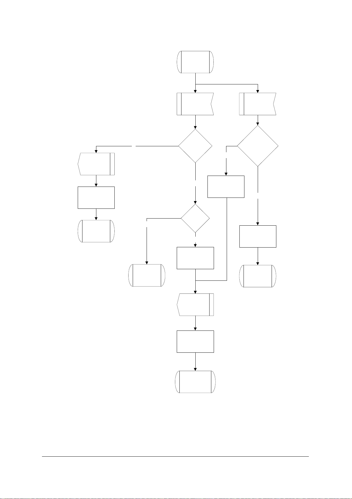
SELECTING
DHCP-
DISCOVER
Set Ts
SELECTING
Ts Expiry
retrans-
N
N
missions
finished ?
Y
Any saved
offers ?
Y
Select offer
N
Reset Ts
DHCP-
OFFER
Is
!("Static VSI
Config") &
VSI was not
received ?
Y
Save offer
START
DHCP-
REQUEST
Set Tr
REQUESTING
SELECTING
Figure 11 - SELECTING state
nanoBTS Product Description DHCP
© ip.access Ltd Page 43
Page 49
REQUESTING
DHCP-NACK
START
N
DHCP-
DECLINE
DHCP-ACK
Reset Tr
Perform Check of
IP Address
(e.g. ARP)
IP Address
Acceptable
?
Y
Set & save "i/f IP
Config"
Set & save "IP
Gateway Config"
Save VSI if
present AND
static VSI config
flag NOT set
Set T1 & T2 &
Lease Timer
Tr Expiry
retrans-
missions
finished ?
Y
START
N
DHCP-
REQUEST
Set Tr
REQUESTING
Use the VERY long lease
time (126 years!) to
change to static config
1
Figure 12 - REQUESTING state
nanoBTS Product Description DHCP
© ip.access Ltd Page 44
Page 50
1
Static
VSI
Y
Y
config?
N
DHCP
VSI
supplied
?
N
BOUND
DHCP-
INFORM
Set Ti
AWAITING
DHCP VSI
For VSI
only
Figure 13 - Connector '1'
nanoBTS Product Description DHCP
© ip.access Ltd Page 45
Page 51
BOUND
unicast to leasing
server
(includes request
for VSI options)
T1 Expiry
Set Tr
((Remaining time
to T2)/2)
DHCP-
REQUEST
RENEWING
NOTES
Lease Expiry
Remove i/f IP
Address
START
1) T1, T2 & Lease Timer are not running if using a fixed
IP Address
Design assumes that
T1 expiry time < T2 expiry timer < Lease expiry time
2) If the VSI is known, it should be used to attempt to
contact the BSC (even if it is known from a previous
config).
3) If no VSI is known, the BTS should passively await
configuration through the BTS A-bis port.
Figure 14 - BOUND state
nanoBTS Product Description DHCP
© ip.access Ltd Page 46
Page 52
RENEWING
DHCP-ACK
Set T1 & T2 &
Lease Timer
Any
Config
Changed?
5
Y
Update saved IP
Address and IP
Config + any VSI
updates
Tr Expiry
DHCP-
REQUEST
Set Tr
((Remaining time
toT2)/2)
RENEWING
DHCP spec says "inform
the user" - attempt to send
Warning FER if connected
to an OML system.
Unicast
T2 Expiry
DHCP-
REQUEST
Set Tr
((Remaining time
to Lease expiry)/2)
REBINDING
Broadcast
Lease
Expired
Remove i/f IP
Address
START
DHCP-NACK
Remove i/f IP
N
BOUND
Address
Apply "IP Config"
& "IP Gateway
Config"
Effectively, this means a
BTS reboot to reset the IP
stack - means address will
be re-acquiredand as
DHCP state will be back to
START.
Figure 15 - RENEWING state
nanoBTS Product Description DHCP
© ip.access Ltd Page 47
Page 53
REBINDING
N
Set Tr
((Remaining time
to Lease expiry)/2)
DHCP-
REQUEST
Broadcast
REBINDING
Tr Expiry
retrans-
missions
finished ?
Y
Any saved
offers ?
Y
Select offer
DHCP-ACK
N
Wait for
Lease expiry
Is
!("Static VSI
Config") &
VSI was not
received ?
Y
Save offer
N
Reset Tr
5
DHCP-NACK
Remove i/f IP
Address
START
Lease
Expired
N
Any saved
offers ?
Y
Select offer
5
5
REBINDING
Figure 16 - REBINDING state
nanoBTS Product Description DHCP
© ip.access Ltd Page 48
Page 54
AWAITING
GATEWAY
CONFIG
Ti Expiry
retrans-
Y
Set & Save
missing "IP
Gateway Config"
to defaults
1 1
missions
finished ?
N
DHCP-
INFORM
Set Ti
DHCP-ACK
Reset Ti
Set & save "IP
Gateway Config"
Save VSI if
present AND
"Static VSI Config"
flag NOT set
AWAITING
GATEWAY
CONFIG
Figure 17 - AWAITING GATEWAY CONFIG state
nanoBTS Product Description DHCP
© ip.access Ltd Page 49
Page 55

AWAITING
DHCP VSI
Y
BOUND
Ti Expiry
retrans-
missions
finished ?
N
N
DHCP-
INFORM
Set Ti
Set Ti
AWAITING
DHCP VSI
AWAITING
DHCP VSI
DHCP-ACK
Reset Ti
Includes
VSI ?
Save VSI
BOUND
Figure 18 - AWAITING DHCP VSI state
nanoBTS Product Description DHCP
© ip.access Ltd Page 50
Page 56

8 CUSTOMER SAFETY AND REGULATORY INFORMATION
8.1 Introduction
8.1.1 Purpose and Scope
This section provides the customer with safety and regulatory warnings, cautions and
information.
Products covered are the model 108, 110, 139, 140, 165 and 178 range of nanoBTSs,
model 109 and 126 power supplies.
8.1.2 Terminology
UL Underwriters Laboratories
FCC Federal Communications Commission
IC Industry Canada
CE European Union
8.2 Model 109 Power Supply
8.2.1 109 - Handbook - Warnings and Cautions
This document is written in English.
Please request a copy in your local language if required.
This product is only intended to power products approved by IP Access.
Ensure that only IP Access products are connected to an Ethernet circuit enabled
for 48V operation. This also applies to outlets remote from the unit.
For indoor use only, output cabling is SELV / LAN for indoor routing only.
Do not cover casing or otherwise impede cooling.
Do not apply power to unit if there is any evidence of condensation.
Do not open casing as mains voltages may be present within the unit.
90 to 264VAC input is via a 2 pin IEC C7 (figure 8) connector. Inlet cable
assembly must carry a suitable local approval (e.g. UL marked for US and
Canadian markets).
nanoBTS Product Description Customer safety and regulatory information
© ip.access Ltd Page 51
Page 57

PSU109 – Environmental Specification
• −10 °C to +45 °C ambient operating temperature.
• This product has been listed by UL for use in a 25 °C ambient.
• −20 to +80 °C ambient storage temperature.
• 5 to 95% RH non-condensing humidity.
8.2.2 109 - Handbook - FCC Text
WARNING
This is a class B product. In a domestic environment this product may cause radio
interference, in which case the user may be required to take adequate measures.
Federal Communications Commission
Note: This equipment has been tested and found to comply with the limits for a class B
digital device, pursuant to part 15 of the FCC rules. These limits are designed to provide
reasonable protection against harmful interference when the equipment is operated in a
commercial environment. This equipment generates, uses, and can radiate radio
frequency energy and, if not installed and used in accordance with the instruction manual,
may cause harmful interference to radio communications. Operation of this equipment in a
residential area is likely to cause harmful interference in which case the user will be
required to correct the interference at his own expense.
8.2.3 109 - Handbook - Industry Canada text
This Class B digital apparatus complies with Canadian ICES-003.
Cet appareil numériqué de la classe B est conformé à la norme NMB-003 du Canada.
8.2.4 109 - Handbook - Regulatory Compliance Statement
EMC Standards
• EN 55022 and EN55024 (CE marked)
• FCC Part 15 class B
• ICES-003
Safety Standards
• EN60950 (CE marked)
• UL60950 Listed (File number E231617) (USA and Canada)
"Hereby, ip.access declares that this Ethernet Power Inserter is in compliance with the
essential requirements and other relevant provisions of Directives 73/23/EEC and
89/336/EEC."
nanoBTS Product Description Customer safety and regulatory information
© ip.access Ltd Page 52
Page 58

The PSU109 is supplied by Poly-Products Industries, model number ILA1711112.
A copy of regulatory compliance documentation may be obtained in writing from:
"IP access Ltd, Building 2020, Cambourne Business Park, Cambourne, Cambridge, CB23
6DW, UK".
8.3 Model 126 Ethernet Switch and Power Inserter
8.3.1 126 - Handbook - Warnings and Cautions
This document is written in English.
Please request a copy in your local language if required.
This product is only intended to power products approved by IP Access.
Ensure that only IP Access approved products are connected to an Ethernet
circuit enabled for 48V operation, this also applies to outlets remote from the unit.
To be located in a restricted access location only (accessible to maintenance
personnel only).
For indoor use only, output cabling is SELV / LAN for indoor routing only.
Do not block ventilation holes or otherwise impede cooling.
Refer to National Engineering Code (USA). Wiring methods must be in
accordance with NEC Article 300.
When rack mounting, secure via front panel plate with 4 bolts and ensure that no
additional load is placed upon the caseworks (e.g. heavy objects on top).
When rack mounting, ensure that the internal rack temperature does not exceed
the rating of this product.
Do not apply power to unit if there is any evidence of condensation.
Do not open casing as mains voltages may be present within the unit.
AC inlet cable must carry suitable local approval (e.g. UL marking for US and
Canadian markets).
nanoBTS Product Description Customer safety and regulatory information
© ip.access Ltd Page 53
Page 59

126 - Input Power Source Specification
• Unit may be powered via AC or DC (not both).
• 90 to 132 and 180 to 264VAC (auto-ranging) via an IEC C13 connector. 135W, 2A
rating.
• 47 to 57V DC via screw terminals on the front panel. 115W 3A rating. The installer
must ensure that this supply connection is fused externally at 5A and provision is
made for an external disconnection device.
• Appliance must be earthed, either via the mains connector (mains operation) or
screw terminal on the front panel (DC operation).
126 – Environmental Specification
• −5 °C to +45 °C ambient operating temperature.
• −20 to +80 °C ambient storage temperature.
• 5 to 95% RH non-condensing humidity.
8.3.2 126 - Handbook - FCC Text
WARNING
This is a class A product. In a domestic environment this product may cause radio
interference, in which case the user may be required to take adequate measures.
Federal Communications Commission
Note: This equipment has been tested and found to comply with the limits for a class A
digital device, pursuant to part 15 of the FCC rules. These limits are designed to provide
reasonable protection against harmful interference when the equipment is operated in a
commercial environment. This equipment generates, uses, and can radiate radio
frequency energy and, if not installed and used in accordance with the instruction manual,
may cause harmful interference to radio communications. Operation of this equipment in a
residential area is likely to cause harmful interference in which case the user will be
required to correct the interference at his own expense.
8.3.3 126 - Handbook - Industry Canada text
This Class A digital apparatus complies with Canadian ICES-003.
Cet appareil numériqué de la classe A est conformé à la norme NMB-003 du Canada.
nanoBTS Product Description Customer safety and regulatory information
© ip.access Ltd Page 54
Page 60

8.3.4 126 - Handbook - Regulatory Compliance Statement
The nanoBTS conforms to the following regulatory standards.
EMC Standards
• EN 55022 and EN55024 (CE marked)
• FCC Part 15 class A
• ICES-003
Safety Standards
• EN60950 (CE marked)
• IEC 60950
• UL60950 Listed (File number E230296) (USA and Canada)
• CB certificate (DK-7033)
"Hereby, ip.access declares that this Ethernet Switch / Power Inserter is in compliance
with the essential requirements and other relevant provisions of Directives 73/23/EEC and
89/336/EEC."
A copy of regulatory compliance documentation may be obtained in writing from:
"IP access Ltd, Building 2020, Cambourne Business Park, Cambourne, Cambridge, CB23
6DW, UK".
8.4 nanoBTS Products
8.4.1 nanoBTS - Handbook - Warnings and Cautions
This system is designed to be operated indoors as a fixed system device and
must be located either on or near the ceiling away from the user. It must be
mounted in a manner to ensure that all users and bystanders are kept a minimum
of 20cm away from the integral antennas at all times.
Do not touch or move the antenna(s) while the unit is transmitting or receiving.
Do not hold any component containing a radio such that the antenna is very close
to or touching any exposed parts of the body, especially the face or eyes while
transmitting.
In most parts of the world, regulatory approval(s) are needed before the nanoBTS
is operated.
Do not connect any device other than the nanoBTS to any RJ45 socket that has
been enabled for nanoBTS connection (i.e. 48Vdc operation).
nanoBTS Product Description Customer safety and regulatory information
© ip.access Ltd Page 55
Page 61

The nanoBTS is intended for dry indoor applications only. If evidence of
condensation is present do not apply power to the nanoBTS.
The nanoBTS must only be powered using an ip.access model 109 PSU (PPI
part number ILA1711112) or ip.access model 126 Ethernet switch and power
inserter (unless prior written approval is obtained from IP Access). Model 165
BTS’s may also be powered by a direct 48V connection using a PSU specified in
writing by IP Access Ltd.
PSUs supplied by ip.access must not be used for powering any other equipment
(unless carried out in a manner having prior written approval from IP Access).
TIB ports on the NanoBTS may only be connected with ip.access supplied cables
with part numbers 139-040, 139-041, 139-042, 139-043 or 165-076.
Fitting external antenna or antenna cabling to the BTS invalidates the type
approval, CE marking and UL listing referred to herein (unless carried out in a
manner having prior written approval from IP Access).
Maximum cable length from the Ethernet Hub, Switch or PSU is limited to 100m.
8.4.2 nanoBTS - Handbook - Parts required for each nanoBTS
• WALL FIXINGS: These are not normally provided as part of the NanoBTS but should
be suitable for the wall material and weight of the NanoBTS (2.7kg). Suggested
materials are 4 x 30mm no.10 woodscrews or M5 bolts and wall plugs (if required).
• PSU.
• nanoBTS complete with mounting bracket.
• RJ45-RJ45 connecting leads.
8.4.3 nanoBTS - Handbook - Provision of Power to the nanoBTS
Power for the nanoBTS may be inserted at either the RJ45 outlet or at the output of the
last Ethernet switch/hub/router etc. see figure below.
nanoBTS Product Description Customer safety and regulatory information
© ip.access Ltd Page 56
Page 62
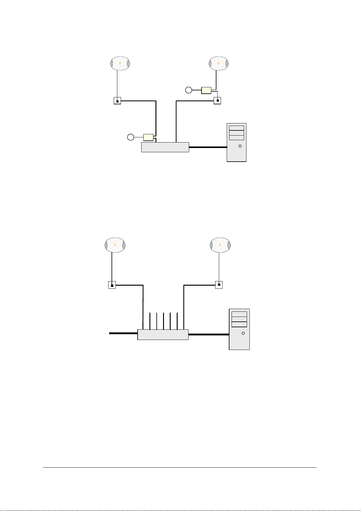
RJ45
nanoBTS
(48v)
PSU θθθθ
~
Ethernet Switch
nanoBTS
PSU φφφφ
~
RJ45
θθθθ PSU located at the switch
BSC
φφφφ PSU located at nanoBTS
When using the ip.access model 126A Ethernet Switch and Power Inserter, external PSU’s
are not required, the nanoBTS is connected locally or via site cabling to the powered ports
of the 126.
nanoBTS (max qty 7)
RJ45
(48v)
~
RJ45
Ethernet
(48V)
126A Ethernet Switch
and 48V Power Inserter
BSC
8.4.3.1 nanoBTS - Handbook - Installing the PSU at the Ethernet switch
If the 109 PSU is located at the patch panel /output port of the Ethernet switch, it is
important that the 109 PSU is connected exactly as illustrated below (failure to do so may
cause damage to the switch). Ensure that the 109 PSU is placed in a location that is
ventilated and that the connection leads provide no safety hazard.
nanoBTS Product Description Customer safety and regulatory information
© ip.access Ltd Page 57
Page 63
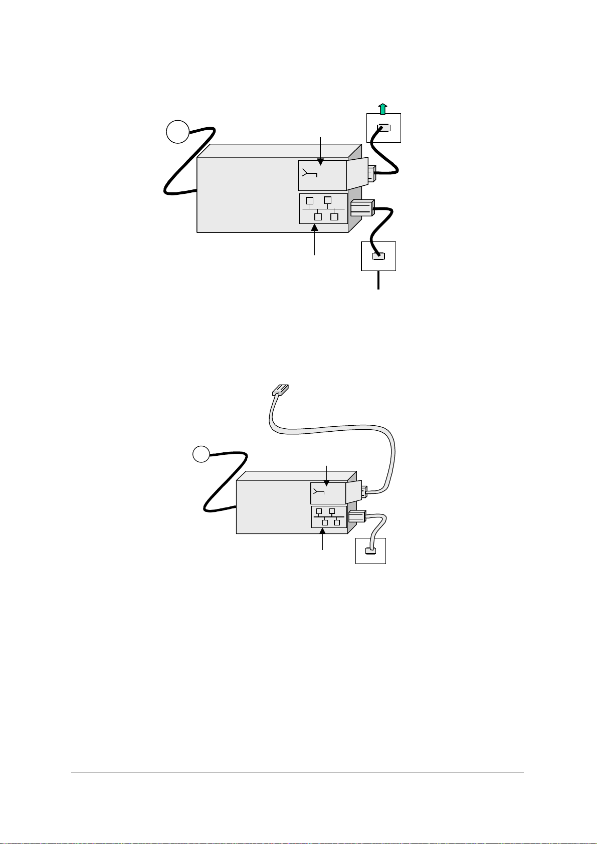
110-230Vac
Cable to nanoBTS
~
Connection to nanoBTS
48Vdc
c
d
!
V
8
4
PSU
RJ45
Connection to LAN
Ethernet Switch
8.4.3.2 nanoBTS - Handbook - Installing the PSU at the nanoBTS
Ensure that the 109 PSU is placed in a location that is ventilated and that the connection
leads provide no safety hazard.
110-230Vac
~
Connection to nanoBTS
48Vdc
PSU
Connection to LAN
c
d
!
V
8
4
RJ45
8.4.4 nanoBTS - Handbook - FCC Text
Standards
• FCC Rule 47 Parts 2, 15, 24
Note: Changes or modifications not expressly approved by the party responsible for
compliance may void the user's authority to operate this equipment.
Model 110 nanoBTS has FCC ID QGGM180TVX
Model 140 nanoBTS has FCC ID QGGKU02ZZT
nanoBTS Product Description Customer safety and regulatory information
© ip.access Ltd Page 58
Page 64

Model 165B nanoBTS has FCC ID QGGKU02ZZP
Model 165D nanoBTS has FCC ID QGGKU02ZZR
Model 165F nanoBTS has FCC ID QGGKU02ZZP
Model 165H nanoBTS has FCC ID QGGKU02ZZS
Federal Communications Commission
Note: This equipment has been tested and found to comply with the limits for a class A
digital device, pursuant to part 15 of the FCC rules. These limits are designed to provide
reasonable protection against harmful interference when the equipment is operated in a
commercial environment. This equipment generates, uses, and can radiate radio
frequency energy and, if not installed and used in accordance with the instruction manual,
may cause harmful interference to radio communications. Operation of this equipment in a
residential area is likely to cause harmful interference in which case the user will be
required to correct the interference at his own expense.
8.4.5 nanoBTS - Handbook - IC Text
Standards
• RSS133 issue 2
Note: Changes or modifications not expressly approved by the party responsible for
compliance may void the user's authority to operate this equipment.
Model 110 nanoBTS has IC (Industry Canada) ID 4644A-M180TVX
Model 140 nanoBTS has IC (Industry Canada) ID 4644A-KU02ZZT
Model 165B nanoBTS has IC (Industry Canada) ID 4644A-KU02ZZP
Model 165D nanoBTS has IC (Industry Canada) ID 4644A-KU02ZZR
Model 165F nanoBTS has IC (Industry Canada) ID 4644A-KU02ZZP
8.4.6 nanoBTS - Handbook - Regulatory Compliance Statement
The nanoBTS conforms to the following regulatory standards:
Type Approvals
• GSM essential requirements under article 3.2 of the R&TTE directive ETSI EN 301
502. CE Marking (CE0168).
• FCC - see above.
• IC – see above.
EMC Standards
• ETSI EN 301 489-1 and –8, ETSI EN 301 502.
• FCC - see above.
• IC – see above.
nanoBTS Product Description Customer safety and regulatory information
© ip.access Ltd Page 59
Page 65

Environmental Standards
• ETS 300 019.
Safety Standards
• EN60950 (CE Marking)
• IEC 60950
• UL60950 Listed (file number E230296, USA and Canada)
• CB Certificate
"Hereby, ip.access declares that this NanoBTS is in compliance with the essential
requirements and other relevant provisions of Directive 1999/5/EC."
A copy of regulatory compliance documentation may be obtained in writing from:
"IP access Ltd, Building 2020, Cambourne Business Park, Cambourne, Cambridge, CB23
6DW, UK".
nanoBTS Product Description Customer safety and regulatory information
© ip.access Ltd Page 60
 Loading...