


nano3GAP Installation Manual
N3G_INST_300 2.0
ip.access Ltd
Building 2020
Cambourne Business Park
Cambourne
Cambridgeshire CB23 6DW
United Kingdom
www.ipaccess.com

Revision History
Version Change Summary Date Author
0.1 First draft 29 Apr 09 ZN1
0.2 Updated from feedback 06 May 09 ZN1
0.3 Updated from further feedback 07 May 09 ZN1
0.4 Updated from review comments 08 May 09 ZN1
0.5 Added license texts, updated with minor comments 12 May 09 ZN1
0.6 Updated the instructions on deployment commissioning 05 Jun 09 ZN1
0.7 Updated with input from System Testing 24 Jul 09 ZN1
0.8 Updated from feedback from System Testing 27 Jul 09 ZN1
0.9 Added instructions to changing the IP configuration of the
27 Jul 09 ZN1
commissioning PC
0.10 Implemented review comments 28 Jul 09 ZN1
0.11 Minor corrections before approval 29 Jul 09 ZN1
1.0 Released for N3G_1.1 29 Jul 09 ZN1
1.1 Added information on type approval and EMC standards
28 Aug 09 ZN1
Updated information on electrical ratings and PSUs
1.2 Implemented review comments 28 Aug 09 ZN1
2.0 Released for N3G_1.1_UPGRADE 28 Aug 09 ZN1
Approved by e-mail.
The information contained in this manual is commercially confidential and must not be
disclosed to third parties without prior consent.
nano3GAP Installation Manual
© ip.access Ltd

Table of Contents
1 Introduction ..................................................................................................... 1
1.1 Installation Overview ......................................................................................... 1
1.2 Related Information...........................................................................................1
1.3 Terminology ...................................................................................................... 2
2 Installation Requirements .............................................................................. 3
2.1 nano3GAP Site Requirements .......................................................................... 3
2.1.1 nano3GAP-4 Site Requirements............................................................................ 3
2.2 Installation Tool Requirements ......................................................................... 6
2.3 Information Needed for Installation ................................................................... 7
2.3.1 Network Information ............................................................................................... 7
2.3.2 AP Configuration File ............................................................................................. 7
3 nano3GAP Hardware Installation .................................................................. 8
3.1 Warnings and Regulatory Information .............................................................. 8
3.2 Hardware Installation - nano3GAP-4 ................................................................ 8
3.2.1 Unpacking the nano3GAP-4 .................................................................................. 8
3.2.2 Mounting the nano3GAP-4..................................................................................... 8
4 Deployment Commissioning of the nano3GAP .........................................11
4.1 Configure the IP Settings of the Provisioning Laptop ..................................... 11
4.2 Configure the Connection to the AP ............................................................... 12
4.3 Set the IP Configuration of the AP .................................................................. 14
5 Configuration of the nano3GAP-4 from the OMC-R................................... 15
5.1 Start the OMC-R Client ................................................................................... 15
5.2 Download the Latest nano3GAP-4 Software Image ....................................... 17
5.3 Create an Attribute Configuration File for the AP............................................ 17
5.4 Download the Attribute Configuration to the AP ............................................. 18
5.5 Perform AP-specific Configuration .................................................................. 18
5.6 Bring the AP into Service ................................................................................ 18
6 Troubleshooting............................................................................................ 19
6.1 Internet Connection Problems ........................................................................ 19
6.2 LED Status Indicators ..................................................................................... 19
6.3 Factory Reset.................................................................................................. 20
nano3GAP Installation Manual
© ip.access Ltd

7 nano3GAP and PSU Regulatory Information .............................................21
7.1 Warnings and Cautions................................................................................... 21
7.2 Regulatory Statements ................................................................................... 22
7.2.1 Type Approval and EMC Standards .................................................................... 22
7.2.2 Safety Standards.................................................................................................. 23
8 Appendices.................................................................................................... 24
8.1 Appendix A - Example AP Configuration File ................................................. 24
8.2 Appendix B - Licenses and Copyright Notices ................................................ 25
8.2.1 asn1c.................................................................................................................... 25
8.2.2 bash...................................................................................................................... 25
8.2.3 BusyBox ............................................................................................................... 25
8.2.4 cramfs................................................................................................................... 25
8.2.5 dropbear ............................................................................................................... 26
8.2.6 glibc ...................................................................................................................... 26
8.2.7 gmp ...................................................................................................................... 26
8.2.8 ipkg....................................................................................................................... 26
8.2.9 iproute2 ................................................................................................................ 26
8.2.10 iptables................................................................................................................. 26
8.2.11 libcurl.................................................................................................................... 26
8.2.12 libgcc .................................................................................................................... 27
8.2.13 libpcap.................................................................................................................. 27
8.2.14 libxml2 .................................................................................................................. 27
8.2.15 Linux Kernel ......................................................................................................... 27
8.2.16 mtd.utils................................................................................................................ 27
8.2.17 ncurses................................................................................................................. 28
8.2.18 NTP daemon........................................................................................................ 28
8.2.19 pcre ...................................................................................................................... 28
8.2.20 procps................................................................................................................... 30
8.2.21 SSL Stack............................................................................................................. 30
8.2.22 StrongSwan.......................................................................................................... 30
8.2.23 TCL....................................................................................................................... 30
8.2.24 tcpdump................................................................................................................ 31
8.2.25 thttpd .................................................................................................................... 31
8.2.26 U-Boot .................................................................................................................. 31
8.2.27 zlib........................................................................................................................ 31
8.2.28 General Licenses ................................................................................................. 31
nano3GAP Installation Manual
© ip.access Ltd

1 Introduction
The ip.access nano3GAP-4 is an indoor pico-class base station.
This document provides the reader with all the necessary information required to install the
ip.access nano3GAP-4. The document provides step-by-step instructions for hardware
installation, PSU Installation, and configuration steps required to bring the nano3GAP-4
into service.
The AP can be configured with a static IP address or it can obtain its IP address
dynamically via DHCP. The AP-AC connection can be configured to be secure (via IPSec)
or unsecured.
1.1 Installation Overview
The principal activities for installing and commissioning a nano3GAP are:
1) Install the nano3GAP hardware and power it up (installation engineer on site,
section 3).
Commission the nano3GAP for connecting to an AC and OMC-R (installation
2)
engineer on site, section 4).
Configure the nano3GAP from the OMC-R to bring it to into service (OAM
3)
engineer remotely from the NOC, section 5).
1.2 Related Information
[GST_100] nano3G System Overview Manual (N3G_GST_100)
[GST_120] nano3G System Planning and Provisioning Manual (N3G_GST_120)
[GST_300] nano3GAP Product Description (N3G_GST_300)
[GST_400] nano3G OMC-R Product Description (N3G_GST_400)
[INST_200] Nano3G AC Installation Manual (N3G_INST_200)
[INST_400] nano3G OMC-R Installation Manual (N3G_INST_400)
[OPM_300] nano3GAP Operations Manual (N3G_OPM_300)
[OPM_410] nano3G OMC-R Client Operations Manual (N3G_OPM_410)
[OPM_430] nano3G OAM File Server Operations Manual (N3G_OPM_430)
[REF_105] nano3G System Glossary (N3G_REF_105)
[REF_150] Iu+ Networking Reference Manual (N3G_REF_150)
[21.905] Vocabulary for 3GPP Specifications, 3rd Generation Partnership Project
nano3GAP Installation Manual Introduction
© ip.access Ltd Page 1

1.3 Terminology
For standard nano3G System terminology, see [REF_105].
For additional standard GSM terminology, see [21.905].
nano3GAP Installation Manual Introduction
© ip.access Ltd Page 2

2 Installation Requirements
2.1 nano3GAP Site Requirements
2.1.1 nano3GAP-4 Site Requirements
The nano3GAPs are installed in retail or small office environments. In summary, each AP
will require:
• One of:
o A suitable mains power supply point within [1.5] metres of the intended AP
site.
o Power over Ethernet (where mains power is remote).
• An Ethernet connection that provides an IP address (via static addressing or via
DHCP) and a route to the public Internet. A DNS service is also required to
resolve symbolic addresses.
• Site for wall mounting or a stable free-standing position.
• Cat5 cable.
2.1.1.1 Power
Maximum expected power consumption: 13 Watts (Rated 9VDC 1450mA)
The nano3GAP-4 supports the following power and Ethernet cabling options at a site:
• Direct power from a power adapter
• Power-over-Ethernet
o from a POE switch
o from a POE inserter
nano3GAP Installation Manual Installation Requirements
© ip.access Ltd Page 3
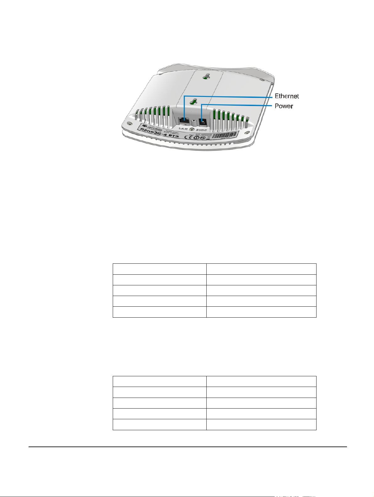
The connections are shown in the figure below.
nano3GAP-4 Ethernet and power connections
The power adapter, as well as the POE inserter and splitter supplied by ip.access comply
with LPS requirements in accordance with IEC/EN 60950-1.
Power Adapter
A suitable mains power supply point into which the power adapter for the AP can be
plugged. This should be within [1.5] metres of the intended installation position of the AP.
Only use the power adapter supplied by ip.access to power the AP:
ip.access part number EPS1173R
manufactured by Dee Van Enterprise Co Ltd.
model DSA-20P-10
input 100-240V ~ 50/60Hz 0.7A
output +9VDC 1.67A
Power over Ethernet
POE comprises of a power inserter and a splitter. The power inserter is positioned close to
the Internet connection, while the splitter is positioned close to the AP.
Only use the POE inserter supplied by ip.access:
ip.access part number 109A
manufactured by PPI Co Ltd
model ILA1711112
input 100/230V ~ 60/50Hz 0.5/0.25A
output 48VDC 0.38A
nano3GAP Installation Manual Installation Requirements
© ip.access Ltd Page 4
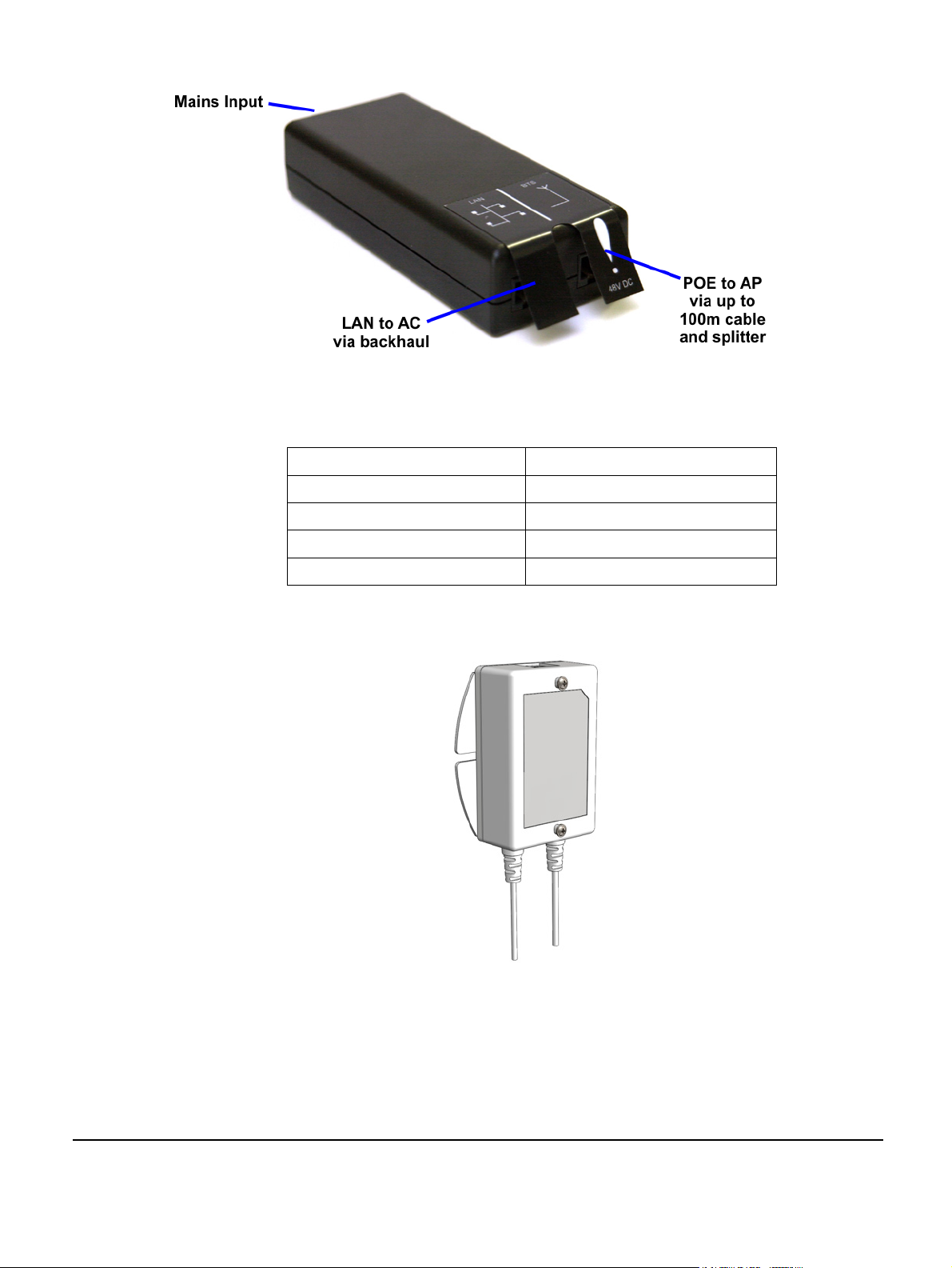
POE inserter
Only use the POE splitter supplied by ip.access:
ip.access part number 222A
manufactured by MIT
model MIT-061-1209-IP
input 48VDC 0.35A
output 9VDC 1.33A
POE splitter
nano3GAP Installation Manual Installation Requirements
© ip.access Ltd Page 5

2.1.1.2 Physical
The nano3GAP may be installed in the following ways:
• free-standing on a flat stable surface (section 3.2.2.1)
•
attached to a wall or partition using the two screws which engage in keyhole slots
in the rear surface of the AP (section 3.2.2.2)
•
attached to a POE splitter using the two screws which engage in keyhole slots in
the rear surface of the AP; the POE splitter in turn attaches to a wall or partition
using two screws (section 3.2.2.3)
Attention sh
ould also be paid to ensuring free air circulation around the unit. The unit must
be vertical.
It is recommended that the AP is installed with its front surface facing the area requiring
cellular coverage, unobscured by walls or partitions that may have significant RF
attenuation.
Dimensions and
Weight
Height 176 mm (without stand)
193mm (with stand)
Width 170 mm
Depth 51 mm
Approximate Weight 0.42 Kg (AP only)
Environmental
Cooling Vents on the back at top and bottom
Operating Temperature 0°C to 40°C
Operating Humidity 10 to 70% non-condensing
2.1.1.3 IP Bandwidth Requirements
At maximum capacity, a 4-Channel nano3GAP will require:
• downlink: at least 5Mbps
• uplink: 512kbps
This will deliver up to 4 voice calls and HSDPA services up to 3.6Mbps.
2.2 Installation Tool Requirements
• To mount the POE splitter or the AP onto the wall:
o 2 self tapping pan head screws, size No. 6 (approx 3.5mm (0.14in) in
diameter)
o suitable drills, screwdriver, etc.
• Provisioning laptop:
o OS: Windows XP
o web browser: Microsoft Internet Explorer 7
nano3GAP Installation Manual Installation Requirements
© ip.access Ltd Page 6

o JavaScript enabled in the web browser
2.3 Information Needed for Installation
2.3.1 Network Information
Installation Engineer:
• subnet information: the installation laptop and the nano3GAP-4 to be configured
must be on the same subnet
• username and password for the AP web server
• address of the security gateway
• address of the serving 3G AC
• ID of this AP on the serving 3G AC
• CRL and NTP server addresses
• DHCP or static IP
• if IPSec is used: Traffic Selector information (IP address and subnet mask)
NOC Engineer:
• Username and password to the OMC-R
• The valid URL to the latest AP software image on the OAM File Server
• Configuration file to be used in the OMC-R Load Attributes Wizard (nano3GAP-4s
hold the master copy of their own configuration and are not pre-provisioned via
the OMC-R)
• Configuration data for the AP:
o MCC
o MNC
o LAC
o SAI
o SAC/LAC
o UARFCN
o Scrambling code
o RNC ID
o RAC
2.3.2 AP Configuration File
Create a separate attributes file for each AP to commission (section 5.3).
nano3GAP Installation Manual Installation Requirements
© ip.access Ltd Page 7

3 nano3GAP Hardware Installation
This section documents the procedure used to install the nano3GAP-4 hardware and
physical connections together with applying the base software configuration.
3.1 Warnings and Regulatory Information
For all warnings and regulatory information, refer to section 7.
3.2 Hardware Installation - nano3GAP-4
3.2.1 Unpacking the nano3GAP-4
1) Unpack the nano3GAP-4, the stand and the POE splitter unit.
Note: No screws are supplied to mount the AP or the splitter unit.
2) Check that the items have not been damaged in transit.
Any damaged units should be returned to the supplier.
3.2.2 Mounting the nano3GAP-4
Note: The nano3GAP-4 should be installed in a position so that it is at least 2m away from the
area where handsets are normally used.
The nano3GAP-4 can be mounted in the following ways:
• on a stand
• directly onto the wall at or above head height
• onto the splitter unit at or above head height
The nano3GAP-4 has 2 holes at the back for the latter two mounting options:
nano3GAP Installation Manual nano3GAP Hardware Installation
© ip.access Ltd Page 8

3.2.2.1 Mounting the nano3GAP-4 on a Stand
1) Plug the Ethernet cable and the power cable into the AP.
2) Slide the AP onto the stand.
3) Place the stand with the AP onto a stable flat surface.
nano3GAP-4 mounted on a stand
3.2.2.2 Mounting the nano3GAP-4 directly onto the wall
1) Drill two holes 70mm (2.76in) apart vertically for the two screws.
2) Insert wall plugs (if required) and secure the screws leaving approximately 3mm
(0.12in) clearance between the screw heads and the wall.
3) Plug the Ethernet cable and the power cable into the AP.
4) Slide the AP onto the 2 screws.
nano3GAP-4 mounted directly on the wall
nano3GAP Installation Manual nano3GAP Hardware Installation
© ip.access Ltd Page 9

3.2.2.3 Mounting the nano3GAP-4 onto the splitter unit on the wall
1) Secure the splitter unit to the wall using two screws.
Ensure that the Ethernet socket is at the top.
2) Plug the Ethernet cable into the splitter unit.
3) Plug the Ethernet cable and the power cable coming from the splitter unit into the
AP.
4) Mount the AP onto the 2 screws that are already fixed onto the splitter unit.
nano3GAP-4 mounted on the POE splitter
nano3GAP Installation Manual nano3GAP Hardware Installation
© ip.access Ltd Page 10
4 Deployment Commissioning of the nano3GAP
Deployment commissioning is performed typically on site, with a provisioning laptop.
The nano3GAP-4 must be in factory reset status for the commissioning. For instructions on
performing a factory reset, see section 6.3.
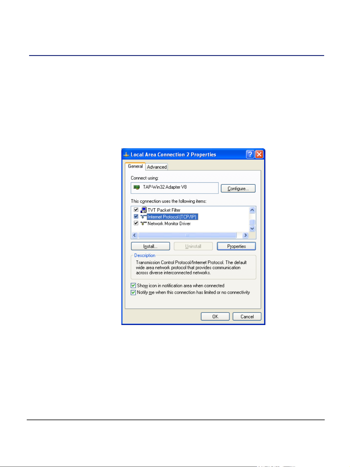
4.1 Configure the IP Settings of the Provisioning Laptop
1) Open the control panel on the laptop.
2) Select Network Connections, select the relevant Local Area Connection, then
right-click Properties.
The following Dialog box appears:
nano3GAP Installation Manual Deployment Commissioning of the nano3GAP
© ip.access Ltd Page 11
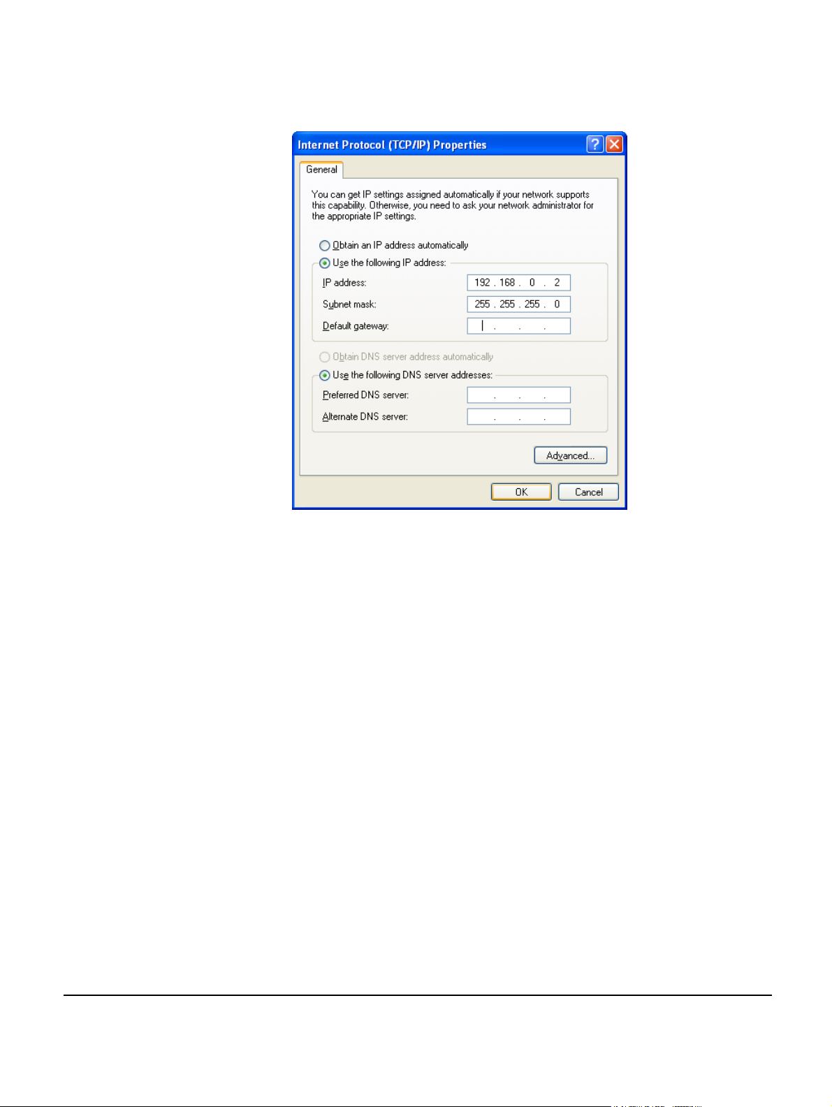
3) Select Internet Protocol (TCP/IP) and then click Properties.
The following Dialog box appears:
4) Change the properties to Use the following IP address.
5) Set the IP Address to 192.168.0.2.
6) Set the Subnet Mask to 255.255.255.0.
Note: The provisioning laptop and the AP must be in the same subnet.
7) Click OK and close the two dialog boxes.
4.2 Configure the Connection to the AP
8) Connect the AP to the Ethernet interface of the provisioning laptop via an
Ethernet cable.
9) Apply power to the AP.
10) Start a web browser on the laptop.
11) Enter the pre-defined static IP address for the web server: 192.168.0.1.
A login screen appears.
nano3GAP Installation Manual Deployment Commissioning of the nano3GAP
© ip.access Ltd Page 12
12) Enter the commissioning username and the password (supplied separately).
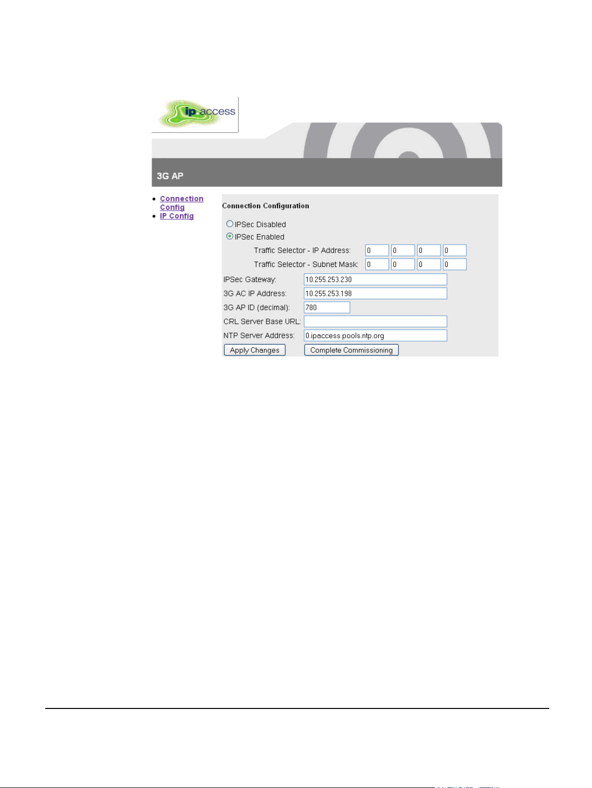
The default page (Connection Configuration) appears.
13) Edit the configuration information:
It is recommended to leave the default NTP server address as default.
Note: The CRL Server Base URL is embedded in the IPSec Gateway address
in the current release. Therefore, this field will be left empty.
14) Save the configuration by clicking Apply Changes.
15) Start the AP in normal operation mode by clicking Complete Commissioning.
16) When the initial configuration is completed, power off the AP and disconnect it
from the laptop.
17) Mount the AP at its intended location, see section 3.2.2.
Connect the AP to the operator network and apply power.
18)
The AP performs its normal, deployed mode start-up and connects to its host AC:
During this procedure, the nano3GAP-4 obtains network time and day information
from the NTP server and – if IPSec is in use – it establishes an IPSec tunnel to
the Security Gateway.
From this point on, the AP can be managed from the OMC-R. It is now ready for initial
configuration by NOC engineers, see section 5.
nano3GAP Installation Manual Deployment Commissioning of the nano3GAP
© ip.access Ltd Page 13
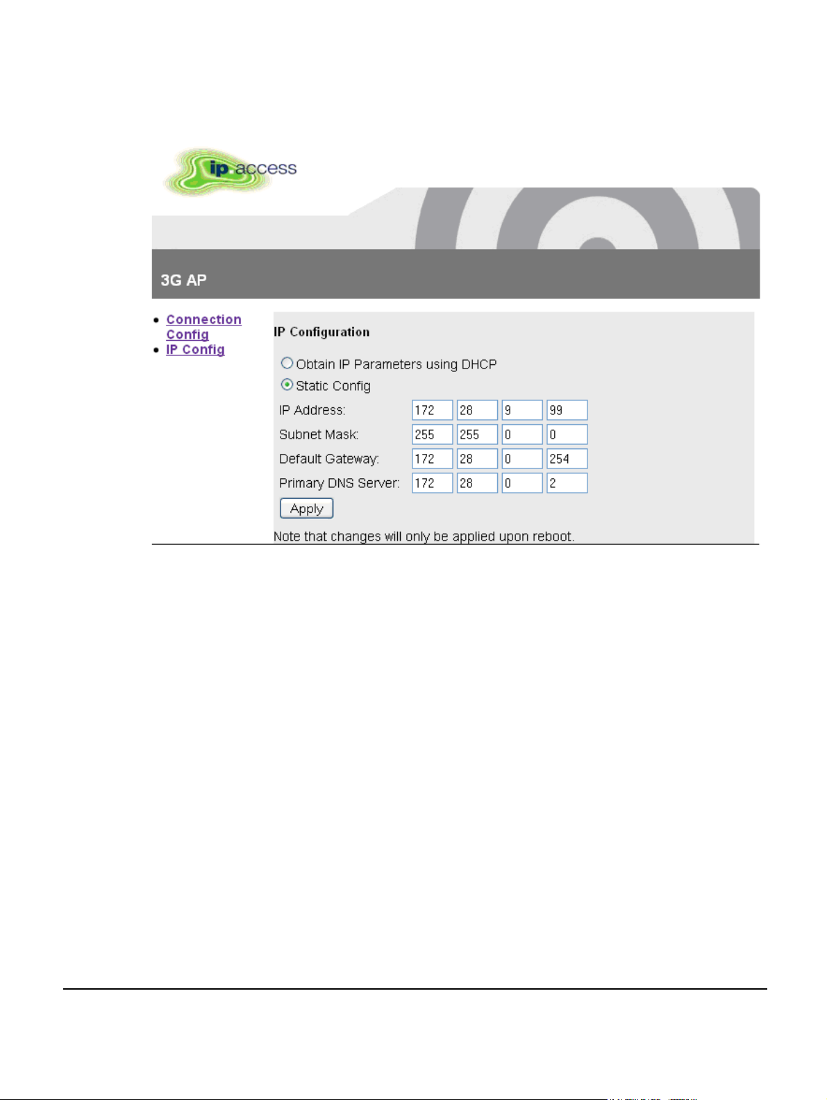
4.3 Set the IP Configuration of the AP
19) Click the IP Config link on the left of the screen.
20) Edit the parameters as needed and then click Apply.
21) Click the Connection Config link on the left of the screen and then click
Complete Commissioning.
22) Read the warning and click OK to complete commissioning.
nano3GAP Installation Manual Deployment Commissioning of the nano3GAP
© ip.access Ltd Page 14

5 Configuration of the nano3GAP-4 from the OMC-R
The nano3GAP-4 needs to be configured before it is brought into service. The NOC
engineer must perform the configuration via the OMC-R Client.
5.1 Start the OMC-R Client
The OMC-R Server provides a web page to start the OMC-R Client.
1) Start a web browser application.
2) Enter the URL for the OMC-R server’s web page as:
http://<server-hostname>/omcr
Where <server-hostname> is the fully qualified hostname of the OMC-R server.
Note: This assumes that DNS is correctly configured on the management
network: the OMC-R server can be found by using its host name from
client computers on the same network.
Note: If a redundant configuration is used, the IP address entered here is a
virtual IP address that will ensure that the connection to the active OMCR Server can be set up without further actions from the client.
3) Press the Enter key and the OMC-R web page will appear.
nano3GAP Installation Manual Configuration of the nano3GAP-4 from the OMC-R
© ip.access Ltd Page 15

4) If it has not been installed on the client computer, click the link to download and
install the Java runtime (JRE version 1.5) for Windows®. This will allow a
Windows® client computer to run the OMC-R Client.
Note: When installed on Windows®, the JRE may automatically update to
version 1.6. The OMC-R Client will operate correctly with JRE 1.6.
However, do not install any version later than 1.6 (or allow JRE to be
automatically updated; for example, decline the update if prompted). The
Java Control Panel may be used to disable automatic updates and/or
disable usage of JRE versions later than 1.6.
5) The OMC-R Client is automatically installed when it is started. Click the link or
icon for Start 3G OMC-R Client.
If this is the first time the OMC-R Client has been started from this client
computer, or if the client version on the OMC-R Server has been updated, the
client application will download (which also installs the application).
If a security warning appears about verification of the digital signature for the
application, click the Run button.
6) The OMC-R Client will initialize and connect to the OMC-R Server. A login prompt
will appear. The first time the client is used from a particular computer, the User
name will be set to the log in ID used for the current session on the client
computer.
7) Enter the username and password, then click OK. The user name will be
remembered at the next login.
8) The OMC-R Client will initialize and connect to the OMC-R Server. The following
screen appears:
nano3GAP Installation Manual Configuration of the nano3GAP-4 from the OMC-R
© ip.access Ltd Page 16

9) Double-click through the tree (Management Views > Configuration Management)
to navigate to the AP to configure.
5.2 Download the Latest nano3GAP-4 Software Image
If the AP already has the latest software version, skip this section.
The latest software image is downloaded to the AP from the OAM File Server. For
instructions about how the software images are uploaded to the OAM File Server, see
[OPM_430].
Make sure that you have the URL to the latest software image file (SDP file)
10)
stored on the OAM File Server.
11) Select the AP in the OMC-R Client.
12) Right-click the AP, select Actions and then Perform Software Download.
13) In the Perform Software Download Actions window, enter the URL of the latest
SDP file.
14) Select whether the image file should be downloaded only, or it should be
swapped with the older image file, and whether the older image file should be
removed from the standby folder on the AP.
15) Click Finish.
The download in progress is indicated by the flashing network LED on the AP.
16) Monitor the 3G AP Admin Package of the AP object in the OMC-R Client.
17) When the standby software version is the version of the downloaded image, rightclick the AP, select Action, and then select Swap Default Software.
18) Right-click the AP object again and then select Reinitialize.
19) Wait for the AP to be shown as connected to the OMC-R.
20) In the 3G AP Admin Package of the AP object, check that the Active Software
Version is that of the new SDP.
5.3 Create an Attribute Configuration File for the AP
The attributes to configure a nano3G-4 AP are stored in a text file. The file can be created
and edited manually in any text editor. For a sample file, see section 8.1.
To create th
21) Log in to the OMC-R (see section 5.1).
22)
23) Save the file under a new name.
e configuration file by using an existing one:
Start the OMC-R Load Attributes Wizard: right-click on any existing AP object in
the OMC-R Client and then select Save Attributes to File.
24) Edit the file in a text editor.
nano3GAP Installation Manual Configuration of the nano3GAP-4 from the OMC-R
© ip.access Ltd Page 17

5.4 Download the Attribute Configuration to the AP
25) Ensure that the attribute configuration file is available on the configuration PC or
at a location reachable from the configuration PC. For information on the AP
configuration file, see section 8.1.
26)
Log in to the OMC-R (see section 5.1).
Start the OMC-R Load Attributes Wizard: right-click on the AP object in the OMC-
27)
R Client and then select Load Attributes From File.
28) Browse to the configuration file and click Apply to load and apply the
configuration settings.
If any of the loaded values are inconsistent with the current state of the AP or if
any of the values are illegal, the wizard displays a warning.
5.5 Perform AP-specific Configuration
29) Perform any AP-specific configurations. In particular, check and modify the
attributes of the following packages as needed:
o Network Listen Control Package
Note: Ensure that the Neighbour List Population attribute is set to Static
Only.
Note: Ensure that the Scan Interval attribute in the package RF Scan Control
is set so that the NWL scan does not disrupt the service. Scheduled NWL
scans should be timed for low-usage time slots. NWL scans can be also
disabled by setting the Scan Interval attribute to 0. In this case, the NWL
scan can be run manually at any time, see the next step.
o Cell Package
o NAS Package
o Location Package
30) Run a Network Listen scan: right-click the AP object, select Actions and then
select Start Sequential NWL Scan.
31) Ensure that the oscillator frequency is correct: select Actions and then select
Apply Frequency Correction.
5.6 Bring the AP into Service
32) Unlock the AP to bring it into service.
The AP now has the latest software image and is ready for service.
nano3GAP Installation Manual Configuration of the nano3GAP-4 from the OMC-R
© ip.access Ltd Page 18

6 Troubleshooting
6.1 Internet Connection Problems
If static IP addressing is disabled and DHCP is in use, the nano3GAP-4 expects to be
automatically provided with an IP address by the broadband router every time it starts.
Ensure that the DHCP service is enabled on the broadband router.
6.2 LED Status Indicators
The following table shows the meaning of the state LED under normal and fault conditions.
Off The nano3GAP-4 is not switched on.
Power
Green The nano3GAP-4 is powered up normally.
Flashing green Self-test is running.
Red There is a fault with the nano3GAP-4.
Note: At power-up, this LED will light solid red by default.
Network
Service
Off Unable to detect a network. This is usually because there is no
network cable connected, or there is no network connection at the
other end of the cable (for example, the router or broadband modem
may have failed or may not be switched on).
Green The 100Mbps connection is OK.
Flashing green Indicates activity on the network at 100Mbps speed (that is, the
nano3GAP-4 is sending and/or receiving data across the LAN).
Amber The 10Mbps connection is OK.
Flashing amber Indicates activity on the network at 10Mbps speed (that is, the
nano3GAP-4 is sending and/or receiving data across the LAN).
Note: This LED is driven by Ethernet hardware.
Off The nano3GAP-4 is not provisioned, it has no IP address. This may
be a temporary condition when you switch on the AP for the first
time, or after you have performed a factory reset.
Green The nano3GAP-4 is provisioned and unlocked.
Flashing green (slow) The nano3GAP-4 is provisioned and locked.
Flashing green (fast) Software download is in progress to the nano3GAP-4.
nano3GAP Installation Manual Troubleshooting
© ip.access Ltd Page 19

6.3 Factory Reset
Factory reset can help in case the AP does not connect. The AP configuration will need to
be redone manually, see section 4.2.
To perform factory reset, press the fa
ctory reset button and hold it for more than 10
seconds.
When the button is initially pressed, the LED will blink fast (50ms on:50ms off) for 5
seconds, then it will start to blink slowly (200ms on: 200ms off). When the factory restore
process has completed, the LED will extinguish and the AP will automatically reboot, take
the fixed IP address and enable the web interface for configuration (see section 4).
nano3GAP Installation Manual Troubleshooting
© ip.access Ltd Page 20

7 nano3GAP and PSU Regulatory Information
This chapter provides the customer with safety and regulatory warnings, cautions and
information for the ip.access Ltd range of products.
7.1 Warnings and Cautions
Electrical Safety
CAUTION
The nano3GAP-4 is intended for dry indoor applications only. If evidence of
condensation is present do not apply power to the nano3GAP-4.
WARNING
Do not immerse any part of the nano3GAP-4 or its power supply in water or any
other liquid. Do not install or use the nano3GAP-4 or its power supply near open
water. Do not spill liquids of any type on the nano3GAP-4 or its power supply.
WARNING
Do not use liquid, solvent or aerosol cleaning agents on or near the nano3GAP-
4 or its power supply.
CAUTION
To avoid the risk of fire and/or electrical shock, do not push objects through
openings into the nano3GAP-4 or its power supply (except when operating the
Reset switch on the nano3GAP-4).
CAUTION
Do not disassemble the nano3GAP-4 or its power supply.
CAUTION
The nano3GAP-4 must only be powered using the ip.access power supply
provided for use with the nano3GAP-4.
CAUTION
Before using the power supply, verify that the mains voltage is within the range
specified by the voltage printed on the power supply.
CAUTION
The PSU supplied with the nano3GAP-4 must not be used for powering any
other equipment.
CAUTION
To avoid the risk of fire and/or electrical shock, do not overload power outlets or
extension cables.
CAUTION
When disconnecting the power supply from the mains, pull the plug. Pulling the
cable may result in damage to the cable.
nano3GAP Installation Manual nano3GAP and PSU Regulatory Information
© ip.access Ltd Page 21
Interference with Electronic Devices
CAUTION
If using a pacemaker, ensure you are using the device in accordance with its
safety requirements with respect to RF devices. Consult your doctor if you have
questions about RF signals and your pacemaker.
CAUTION
If using a hearing aid, RF devices may cause interference.
CAUTION
Unshielded electronic devices should not be used near the nano3GAP-4.
Conversely, the nano3GAP-4 should not be installed adjacent to unshielded
electrical or electronic devices (such as unshielded speakers).
Other Warnings and Cautions
WARNING
Do not install the nano3GAP-4 in a position where the power supply cable or
network cable may cause a tripping or choking hazard.
WARNING
Do not install the nano3GAP-4 or the power supply on an unstable surface. All
caution must be observed to prevent the device from falling and causing injury
to a person and/or damage to the device.
WARNING
The nano3GAP-4 should not be disposed of in household waste bins. Please
follow local regulations for disposal of electronic devices.
CAUTION
Do not install the nano3GAP-4 in a position where the power supply cable or
network cable may be damaged by walking on the cables.
CAUTION
Do not attempt to fit an external antenna or antenna cabling to the nano3GAP-4.
7.2 Regulatory Statements
7.2.1 Type Approval and EMC Standards
• FCC CFR47 Parts 15B, 27
Note: Changes or modifications not expressly approved by the party responsible for compliance
may void the user's authority to operate this equipment.
Model nano3G 219C has FCC ID QGGIPA219C
nano3GAP Installation Manual nano3GAP and PSU Regulatory Information
© ip.access Ltd Page 22

WARNING
This is a class B product. In a domestic environment this product may cause
radio interference in which case the user may be required to take adequate
measures.
Federal Communications Commission
Note: This equipment has been tested and found to comply with the limits for a class B digital
device, pursuant to part 15 of the FCC rules. These limits are designed to provide
reasonable protection against harmful interference when the equipment is operated in a
commercial environment. This equipment generates, uses, and can radiate radio
frequency energy and, if not installed and used in accordance with the instruction manual,
may cause harmful interference to radio communications. Operation of this equipment in a
residential area is likely to cause harmful interference in which case the user will be
required to correct the interference at his own expense.
7.2.2 Safety Standards
• IEC 60950-1:2005 (2nd Edition) and EN 60950-1:2006
The power adapter, as well as the POE inserter and splitter supplied by ip.access comply
with LPS requirements in accordance with IEC/EN 60950-1.
nano3GAP Installation Manual nano3GAP and PSU Regulatory Information
© ip.access Ltd Page 23

8 Appendices
8.1 Appendix A - Example AP Configuration File
A configuration file with the object name and the objects instance (relative distinguished
name) must be created for each AP to be commissioned. For instructions to use the
configuration file, see section 5.3.
The file has
to conform to the following syntax:
• all non-comment lines are of the form <name>=<value>
• comment lines begin with the hash character (#)
• attribute types are as follows:
o integer tos=0
o enumeration t300=T300_4000_MSEC
o array ascPersistenceScalingFactors=[6,6,6,6,6,6]
o boolean soipHeartbeatEnabled=true
o structure cellBroadcastMessage={50,GSM_DEFAULT,”oyster 3G”}
o string “HMAC-SHA1”
o set alarmFilter=()
# Instance for the AP to be modified
Object=apNano_001
ObjectInstance=ROOT#0;AC_CONNECTION#12007;RNS#0;AP_CONTROLLER#
0;AP_CONNECTION#31;AP#0
# Cell Package
rncIdentity=139
# NAS Package
mcc="159"
mnc="12"
sac=1
saiLac=1
# Network Listen Control Package
lacRacCandidateList=({15912,(99)})
rfParamsCandidateList=({1062,437,1})
rssiScanBands=({BAND_NAME_UMTS_BAND_04_NO_SPOT,()})
# end of file
Parameter Description
Object
nano3GAP Installation Manual Appendices
© ip.access Ltd Page 24
ID of the AP

ObjectInstance
rncIdentity
Mcc
Mnc
Sac
saiLac
lacRacCandidateList
rfParamsCandidateList
rssiScanBands
Relative Distinguished Name
ID of the AC
Mobile Country Code
Mobile Network Code
Service Access Code
SAC Location Area Code
LAC and RAC list
Radio Frequency parameter list
Scanning frequency bands for received signal strength
indication
8.2 Appendix B - Licenses and Copyright Notices
Portions of the AP are constructed from third-party software and open source code and
ip.access ltd gratefully acknowledges the contributions that these libraries, technologies
and components have made to the product. Each of these is supplied under the terms of a
license agreement and these are either reproduced or referenced below in line with the
stipulations of their authors.
8.2.1 asn1c
asn1c by Lev Walkin (vlm@lionet.info) is covered by a BSD-type license:
See the file "COPYING" in the source package
8.2.2 bash
bash by GNU is covered by the GNU GPL Version 2, as reproduced in section 8.2.28.1.
8.2.3 BusyBox
BusyBox by BusyBox.net is covered by the GNU GPL Version 2, as reproduced in section
8.2.28.1.
8.2.4 cramfs
cramfs by SourceForge(cramfs) is covered by the GNU GPL Version 2, as reproduced in
section 8.2.28.1.
nano3GAP Installation Manual Appendices
© ip.access Ltd Page 25
 Loading...