

Page 1

Operating Manual
Process photometer
for free chlorine and pH value
AQUACON PH-CL
(PC- Cabinet)
May 2011
Fillerkampsweg 1 – 5 • 31832 Springe OT Eldagsen • Tel.: 0049(0)5044/887-0 (Fax: -99)
E-Mail: [email protected] Internet: http://www.iotronic.de
Page 2

AQUACON PH-CL (PC Cabinet)
Technical Information
Page 2
May 2011
Page 3

AQUACON PH-CL (PC Cabinet)
Technical Information
Page 1
1 GENERAL GUIDELINES FOR SAFETY 3
2 PRINCIPLE OF OPERATION 4
3 DESCRIPTION OF THE PROCESS PHOTOMETER 4
3.1 Analytical Part 7
3.2 Measurement and Control 7
3.3 Operation and Measurement Security 8
3.4 Automatic Operation 9
3.5 Manual Operation 10
3.6 Display/Set Parameters 11
3.6.1 Limit Value 1 pH 12
3.6.2 Limit Value 2 pH 12
3.6.3 Limit Function pH 13
3.6.4 Limit Value 1 Cl2 13
3.6.5 Limit Value 2 Cl2 13
3.6.6 Limit Function Cl2 13
3.6.7 Sampling Intervall 13
3.6.8 Titer/Calibration factor 14
3.6.9 Rinsing time 14
3.6.10 Reagent Volume 14
3.6.11 Analog Output setting (mode) 14
4 SWITCHING FUNCTIONS OF THE AQUACON PH-CL 15
4.1 External Switching 15
4.2 Display in the standby mode 15
4.3 Analysis state relay 15
4.4 Limit Value Relay K2 and K3 16
4.5 Alarm Limit Relay 16
May 2011
Page 4

AQUACON PH-CL (PC Cabinet)
Technical Information
Page 2
4.6 Current Output 16
5 START-UP AND MAINTENANCE INSTRUCTIONS 17
5.1 Connection of sample water 17
5.2 Connection of reagent, bleeding of pumps and tubes 17
5.3 Replenishment of Reagent 17
5.4 Changing of Tube box 18
5.5 Recalibration of the Process analyzer 18
5.6 Maintenance interval 18
5.7 Shut down procedure 18
6 ALARM MESSAGES 19
7 TECHNICAL DATA 19
8 SPECIFICATIONS 20
9 CONNECTION DIAGRAM 20
9.1 Set 0/4 - 20 mA-Output 20
9.2 Connections 21
9.3 Installation 22
10 APPENDIX 23
10.1 Analysis cycle AQUACON PH-CL 23
10.2 Spare part and consumable item list 24
11 TROUBLESHOOTING GUIDE 25
May 2011
Page 5
AQUACON PH-CL (PC Cabinet)
Technical Information
Page 3
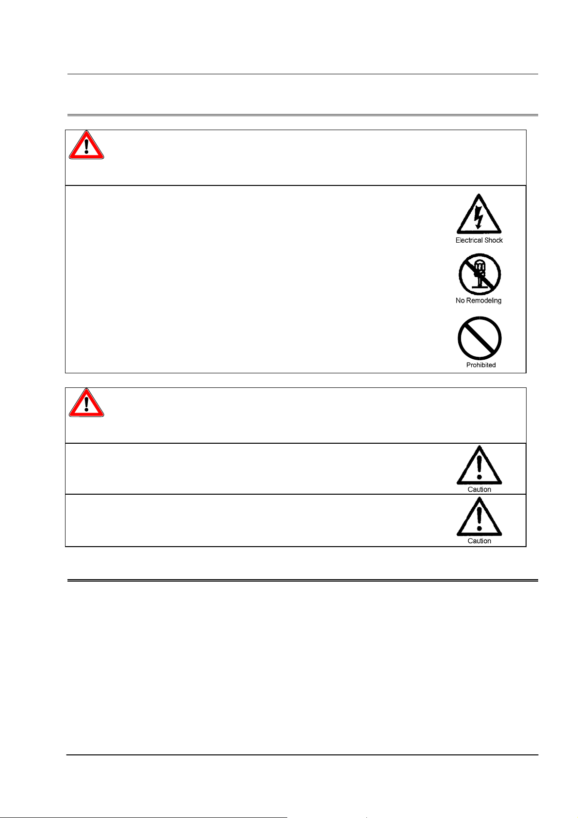
1 General Guidelines for Safety
WARNING
Turn off the power supply.
Working without disconnecting the power supply may cause an electrical
shock. Before engaging upon any working procedures make sure to
disconnect the power supply.
No remodelling !
Never remodel an analyzer. Otherwise, a serious accident may result.
IOTRONIC will not be responsible for any accident or damage of any kind
which is caused by the user remodelling the analyzer.
Operating site must be free of water and humidity
The analytical instrument is not designed to be water-proof or dust-proof.
The use of the analyzer in places where water splashes or humidity is high
may result in an electrical shock or short-circuit.
CAUTION !
Specified power only
Do not operate the analyzer on voltage which is not specified on the label
on the right side of the transmitter housing. Failure to do so can result in
damage or fire. Only the specified power level is to be applied.
Do not damage or change power cable !
Do not scratch, damage, process, or pull the power cable forcibly. Nonobservance could cause a fire or an electrical shock.
(Non-observance or misapplication of the contents
of the “Warning” section could lead to serious
accident, including death or injury)
(Non-observance or misapplication of the
contents of the “Caution” section could lead to
serious physical injury to the user or serious
damage to the product.)
Notes on operation
z
Dropping the device or subjecting it to strong impacts may result in
faulty performance. Handle the analyzer with care.
z
Select an installation site convenient for future maintenance and
inspection, and fix the device carefully so that it is free of vibrations.
May 2011
Page 6

AQUACON PH-CL (PC Cabinet)
Technical Information
Page 4
2 Principle of Operation
The process photometer AQUACON PH-CL performs a discontinuous photometric determination of
the concentration of free chlorine and of the pH value. The measurements are performed one after the
other. The entire operation, which includes filling and rinsing of the measuring cuvette, is controlled
by a microprocessor.
PH value:
A special indicator reagent is added via a peristaltic pump and mixed with the water sample in the
measuring chamber. The color formed as a result of the reaction is detected by the monochromatic
photometric detection system built into the measuring chamber. The measured absorbance is a
function of the pH value.
Free chlorine:
A special developed reagent based on N-N-Diethyl-p-phenylendiaminsulfat (DPD) and a buffering
solution are added via a peristaltic pump and mixed with the water sample in the measuring chamber.
The color formed as a result of the reaction is detected by the monochromatic photometric detection
system built into the measuring chamber. The measured absorbance is a function of the free chlorine
concentration. With this method, the concentration of free chlorine (Cl2), hypochlorous (HOCl),
hypochlorite (OCl-) is measured.
The measurement results for pH value and free chlorine concentration are displayed on the
touchscreen.
3 Description of the Process Photometer
The process photometer is delivered completely mounted in a polycarbonate wall cabinet, ready for
installation. This includes all the components for sample and drain connection, measurement chamber,
reagent pumps, display and connections for remote display and control. All functions of the process
photometer can be operated via touchscreen.
May 2011
Page 7
AQUACON PH-CL (PC Cabinet)
Technical Information
Page 5
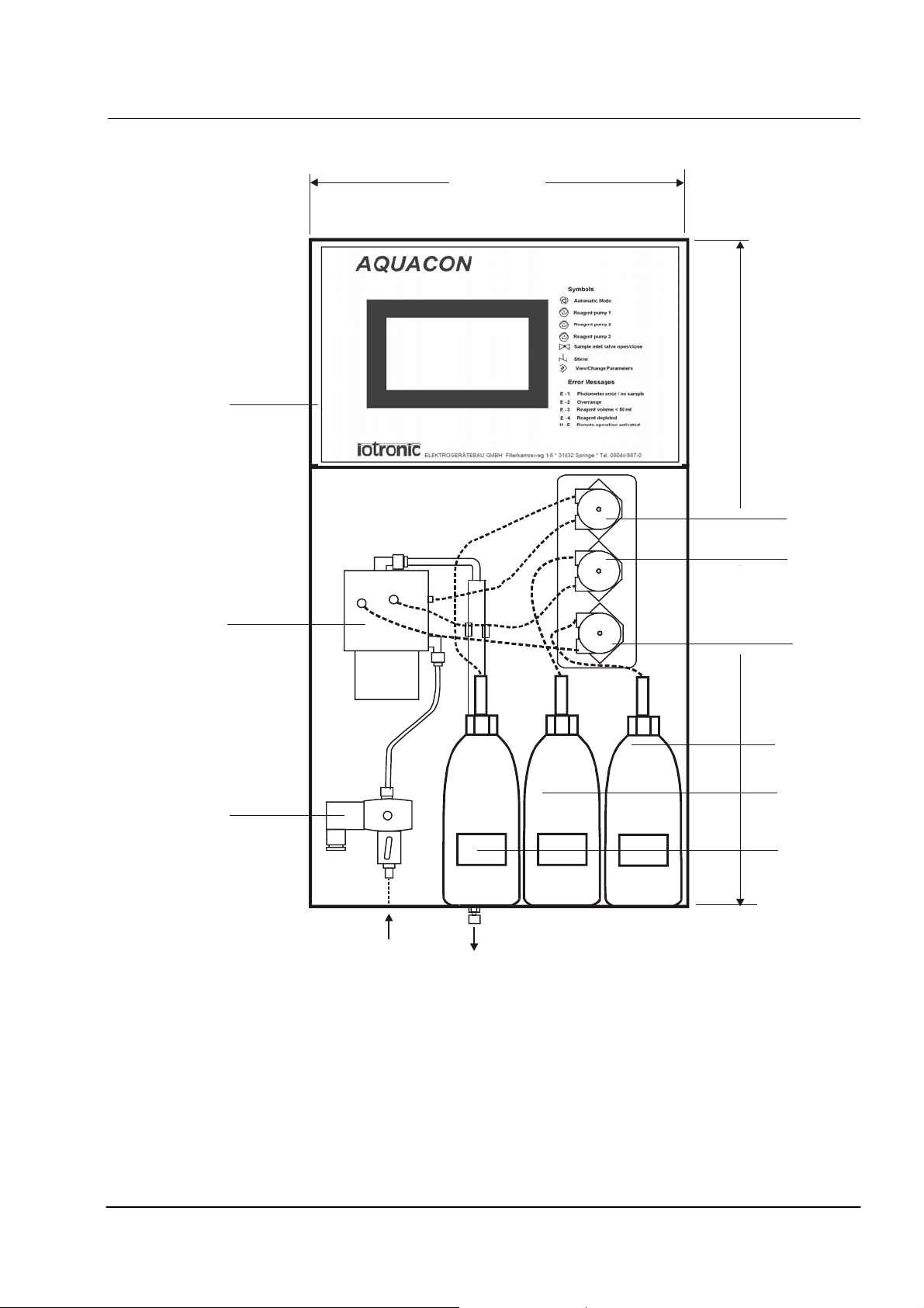
View of the process photometer AQUACON PH-CL
300
AQUACON FE10
1
Automatic Operation
Manual Operation
Mode is selected for the following
drives by pressing the appropiate
key in th e top row
Reagent pump 1+2 on/ off
Reagent pump 3 on/off
Sample Inlet valve open/close
Stirrer on/off
View/Change Parameters
Mode is selected
and contents of parameter 3 to -
are viewed sequentially by
repeated pressing of this key
Alters contents of displayed
parameter
Return to AUTOMATIC mode
1+2 3
Operating Mode /
Parameter
ppb
OPERATING MODE /
PARAMETER DISPLAY
Operating Mode:
Standby
0
Analyzing
1
Manual
2
Display / Set Parameters:
3
Limit value
4
Alarm value
5
Start value for 20 mA Output
6
End value for 20 mA Output
7
Sampli ng int erval (m in)
8
Calibration factor
9
Rinse time (sec)
-
Reagent volume (ml)
Error Messages
Photometer error / Loss
E - 1
of sample
Overrange
E - 2
Reagent volume < 50 ml
E - 3
Reagent depleted
E - 4
Remote operation activated
H - E
2
3
Sample
inlet
Sample
outlet
6
0
0
0
0
7
6
5
4
9
8
7
1 Transmitter
2 Measuring chamber
3 Sample inlet valve
4,5,6 Reagent tube pump
7 Reagent 1 vessel (500 ml)
8 Reagent 2 vessel (250 ml)
9 Reagent 3 vessel (250 ml)
May 2011
Page 8
AQUACON PH-CL (PC Cabinet)
Technical Information
Page 6
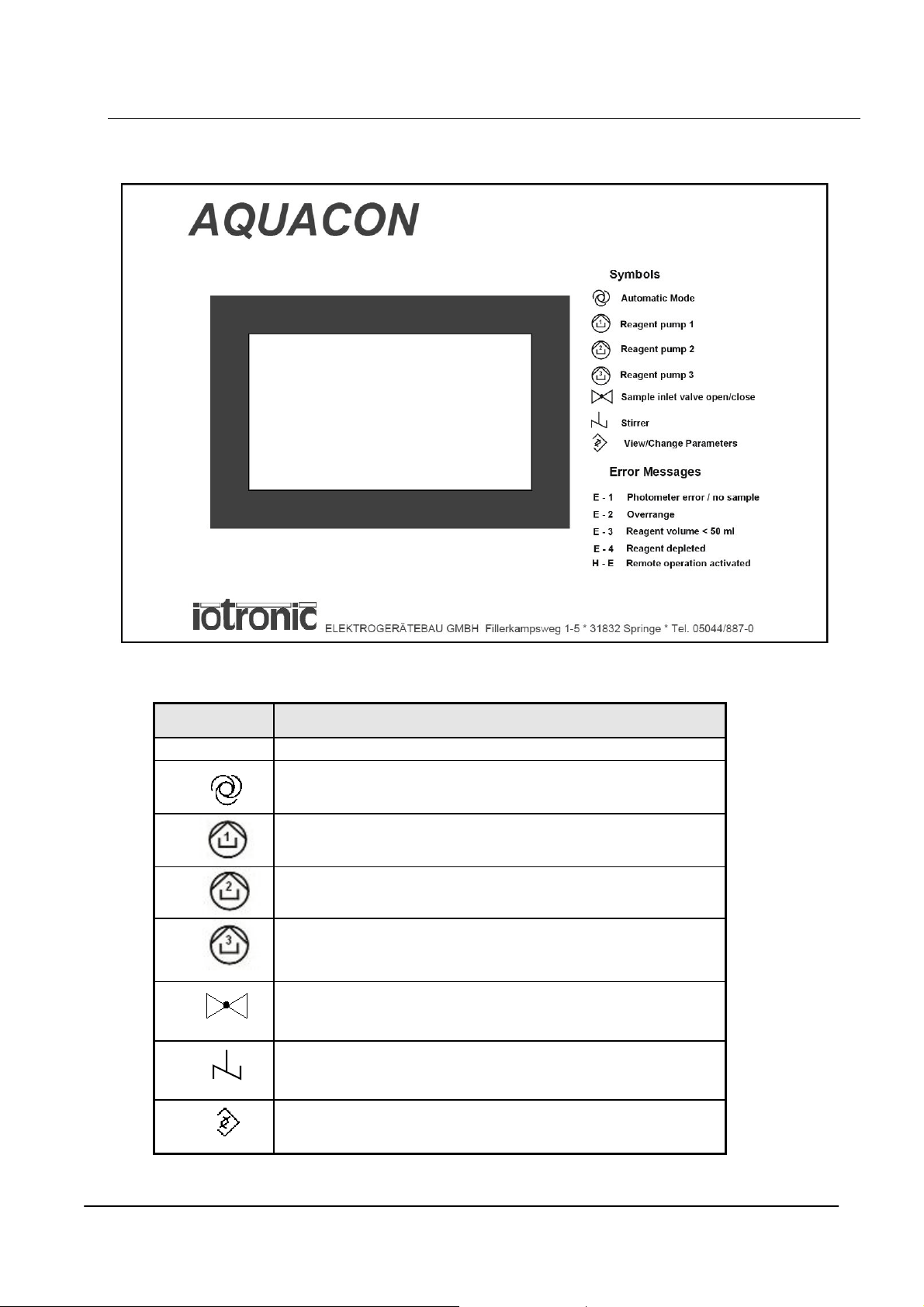
AQUACON PH-CL Display and Keyboard
Symbol Function
Select Automatic Mode, start an analysis
Reagent pump 1 on/off
Reagent pump 2 on/off
Reagent pump 3 on/off
Sample inlet valve open/close
Stirrer on/off
View / Change parameters
Explanation of Symbols
May 2011
Page 9

AQUACON PH-CL (PC Cabinet)
Technical Information
Page 7
3.1 Analytical Part
The transmitter of the process photometer AQUACON PH-CL is contained in a compact housing and
includes the microprocessor which recognizes the absorbance (extinction), displays the final
calculated result on a touch screen and controls the operation of the process photometer with respect
to sampling, rinsing of the measurement chamber, dosing of the reagent and surveillance of the
photodetection system.
3.2 Measurement and Control
Inside the control unit of the analyzer, there is one limit value relay (K2) for the pH value and one
limit value relay (K3) for the free chlorine. Both relays can be operated in min function mode or in
max function mode. For both relay, 2 limit values (limit value 1 and limit value 2) can be
parametrized.
Min function:
If the limit function of the relay K2 or K3 is set as min function, the appropriate relay will be activated
if the measured value is lower than the set limit value 1 for this relay. The relay will be deactivated if
the measured value is higher than the set limit value 2 for this relay.
Max function:
If the limit function of the relay K2 or K3 is set as max function, the appropriate relay will be
activated if the measured value is higher than the set limit value 2 for this relay. The relay will be
deactivated if the measured value is lower than the set limit value 1 for this relay.
In addition, two 0/4 - 20 mA current outputs deliver a signal which is proportional to the measured
values for pH and free chlorine (see chapter 9.1). The start value and the end value of the output range
are fixed for both parameters .
All user-defined settings are maintained during power failure to the instrument.
May 2011
Page 10

AQUACON PH-CL (PC Cabinet)
Technical Information
Page 8
3.3 Operation and Measurement Security
When the end-user defined maximum alarm value is exceeded or when an error occurs (ERROR E-1
to ERROR E-4) the alarm relay will activate.
The actual reagent volume of reagent 1 is calculated by the microprocessor and is corrected for usage
after each analysis. Once the calculated remaining reagent volume falls below the factory-
predetermined value of 50 ml, an alarm message (ERROR E-3) is displayed on the touchscreen and
the alarm relay (found on the transmitter terminal connector) is activated. The remaining 50 ml
reagent is sufficient for appr. 92 analysis. Should this alarm be ignored and the reagent is depleted, a
second alarm message (ERROR E-4) is displayed on the touchscreen, subsequent relay activation is
initiated by the process photometer AQUACON PH-CL and the analyzer stops.
The optical transparency of the measurement cuvette is measured at the start of each analysis. An
automatic zero adjustment takes place before each measurement to compensate colored or turbid
samples or discoloration/contamination of the cuvette windows.
Once the factory-predetermined limit to the zero adjustment is exceeded, another alarm message
(ERROR E-1) is displayed on the touchscreen, the alarm relay is activated and the analysis cycle is
interrupted. In the event of sample failure, the photometer will detect this and display the alarm
message ERROR E-1 on the touchscreen, activate the alarm relay and interrupt the measurement.
When the sample interval defined by the end-user has elapsed, the process photometer will
automatically resume measurement as normal and repeat the procedure until sample flow is re-
established.
The analysis cycle may be interrupted at any stage by touching the button ”Hand” or the button
”Param” on the touchscreen. The process photometer remains in manual operation mode until the
automatic mode is selected by pressing the appropriate symbol or touch button.
May 2011
Page 11
AQUACON PH-CL (PC Cabinet)
Technical Information
Page 9
3.4 Automatic Operation
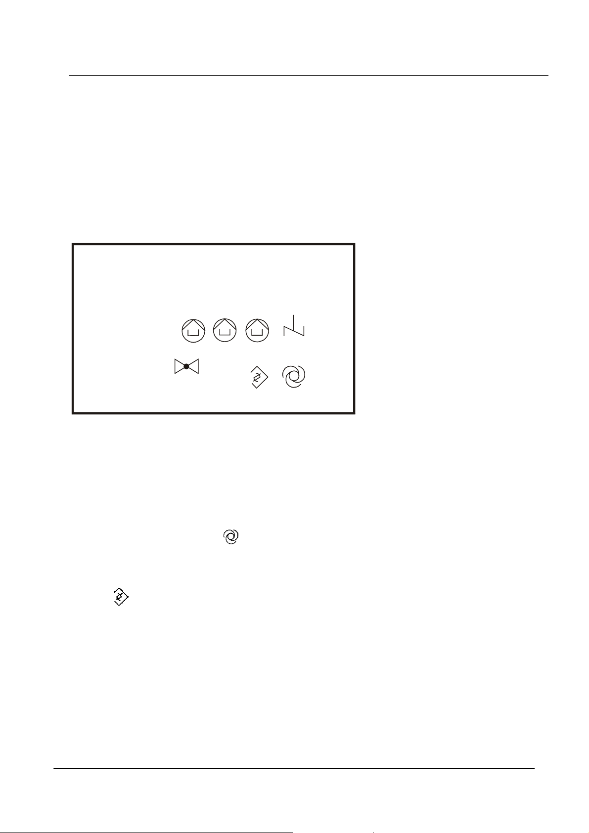
The process photometer will automatically carry out an analysis once the ”Start” button is pressed.
On the return of power, following a power failure, the process photometer will automatically enter the
automatic mode and starts a measurement. This is displayed as state ”MEASURING”.
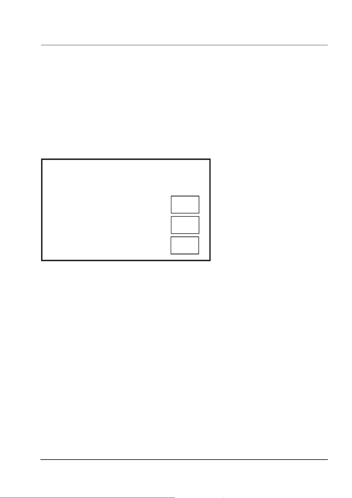
On the touchscreen, the last actual measured values for the pH value and for free chlorine are
displayed. Below the last measured value, the set parameters for the first limit values (LV 1 pH, LV 1
CL2) and for the second limit values (LV 2 pH, LV 2 CL2) are displayed. This values can be
parametrized by the end-user (see chapter 3.6).
AQUACON PH-CL
State: MEASURING
pH: 7,40
Start
Cl2: 0,10 ppm
Hand
LV 1 pH: 7.20
LV 1 Cl2: 0.60
The automatic analysis cycle can be interrupted at any stage by touching the button ”Hand” or the
button ”Param” on the touchscreen (see 3.5). After the finish of the analysis, the new measured value
will be displayed on the touchscreen and the analyzer state is changed to ”STANDBY”.
When the upper measurement range is exceeded, the alarm message “ERROR E-2” is displayed
as state on the touchscreen and the alarm relay is activated.
LV 2 pH: 7.60
LV 2 Cl2: 0.60
Param
May 2011
Page 12
AQUACON PH-CL (PC Cabinet)
Technical Information
Page 10
3.5 Manual Operation
Manual operation of the process photometer is useful for maintenance, commissioning of the analyzer
and when correction of alarm conditions during normal operation occur.
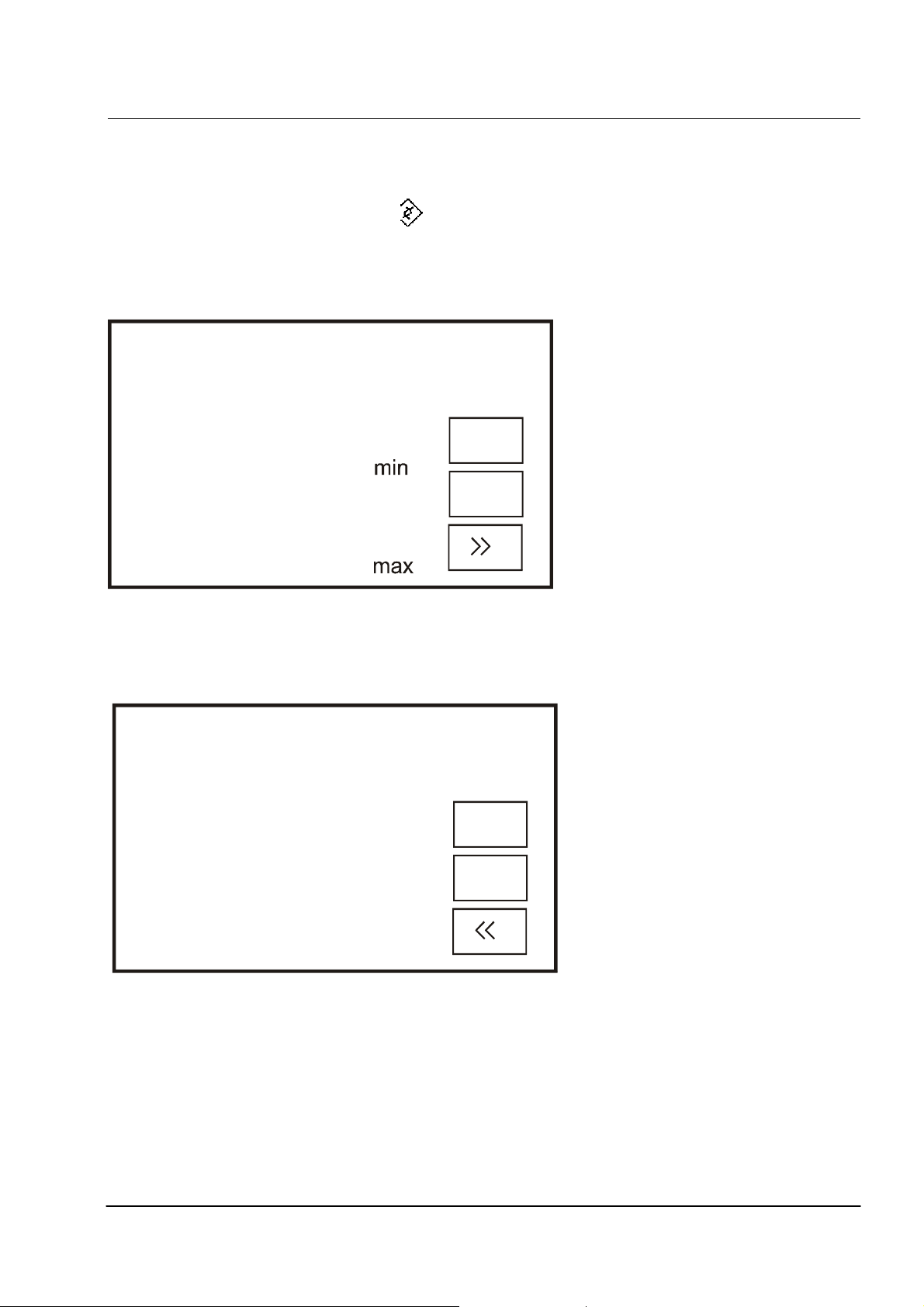
Manual operation of the process photometer is effected by pressing the button ”Hand” on the
touchscreen. During the internal zero adjustment of the photometer short delays can occur. Automatic
operation is interrupted and the screen displays the manual mode (state: MANUAL). Simultaneously,
the actual absorbance (extinction) value is displayed in the upper display.
AQUACON PH-CL
State: MANUAL
Valve
1
2
0,050
3
Pump 1
Pump 2
Pump 3
Stirrer
During manual operation, the pumps, the sample inlet valve and the stirrer can be
activated/deactivated by touching the appropriate symbols. The active part will be displayed with
inverse letters.
During manual operation, the mode can be switched to automatic mode and an analysis can be
started by touching the symbol .
During manual operation, the mode can be switched to parameter mode by touching the
symbol
May 2011
Page 13
AQUACON PH-CL (PC Cabinet)
Technical Information
Page 11
3.6 Display/Set Parameters
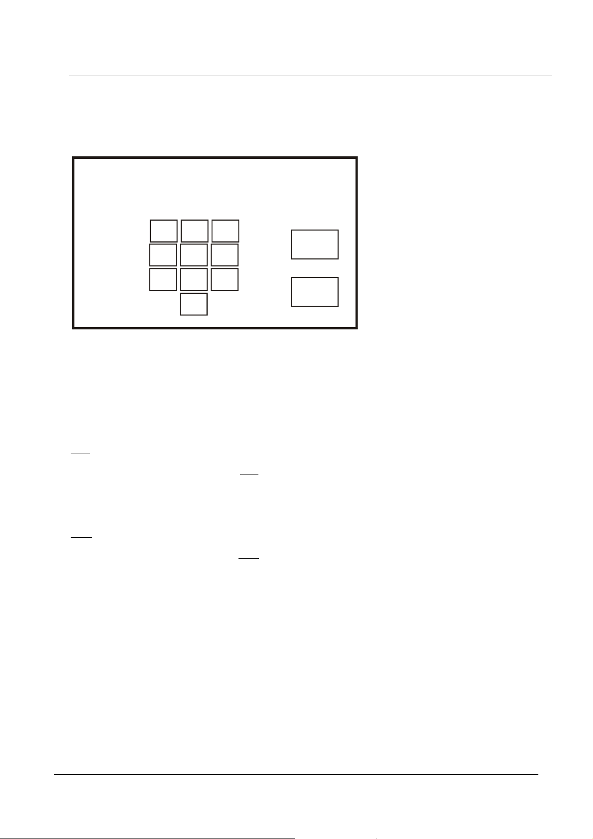
The parameter mode can be activated from automatic mode by touching the button ”Param” or from
manual mode by touching the symbol
In parameter mode, a new screen will be displayed which shows the parameters Limit value 1 pH,
Limit value 2 pH, Limit function pH, Limit value 1 Cl2, Limit value 2 Cl2 and Limit function Cl2.
AQUACON PH-CL
Limit value 1 pH:
Limit value 2 pH:
7.20
7.60
Start
Limit function pH:
Limit value 1 Cl2:
Limit value 2 Cl2:
0.30
0.60
Hand
Limit function Cl2:
By touching the button ” >>” , a second screen will be displayed with the parameters Sampling
interval, Calibration factor, Rinse time, Reagent volume and Output mode.
AQUACON PH-CL
Sampling interval: 10
Calib. factor: 1.00
Start
Rinse time: 15
Hand
Reagent volume: 250
Output mode: 4-20 mA
By touching the button ” << ” , the first parameter screen will be displayed again.
All parameters are set to a certain value (factory settings), but can also be parametrized by the end-
user (see the following chapters 3.6.1 – 3.6.11).
May 2011
Page 14
AQUACON PH-CL (PC Cabinet)
Technical Information
Page 12
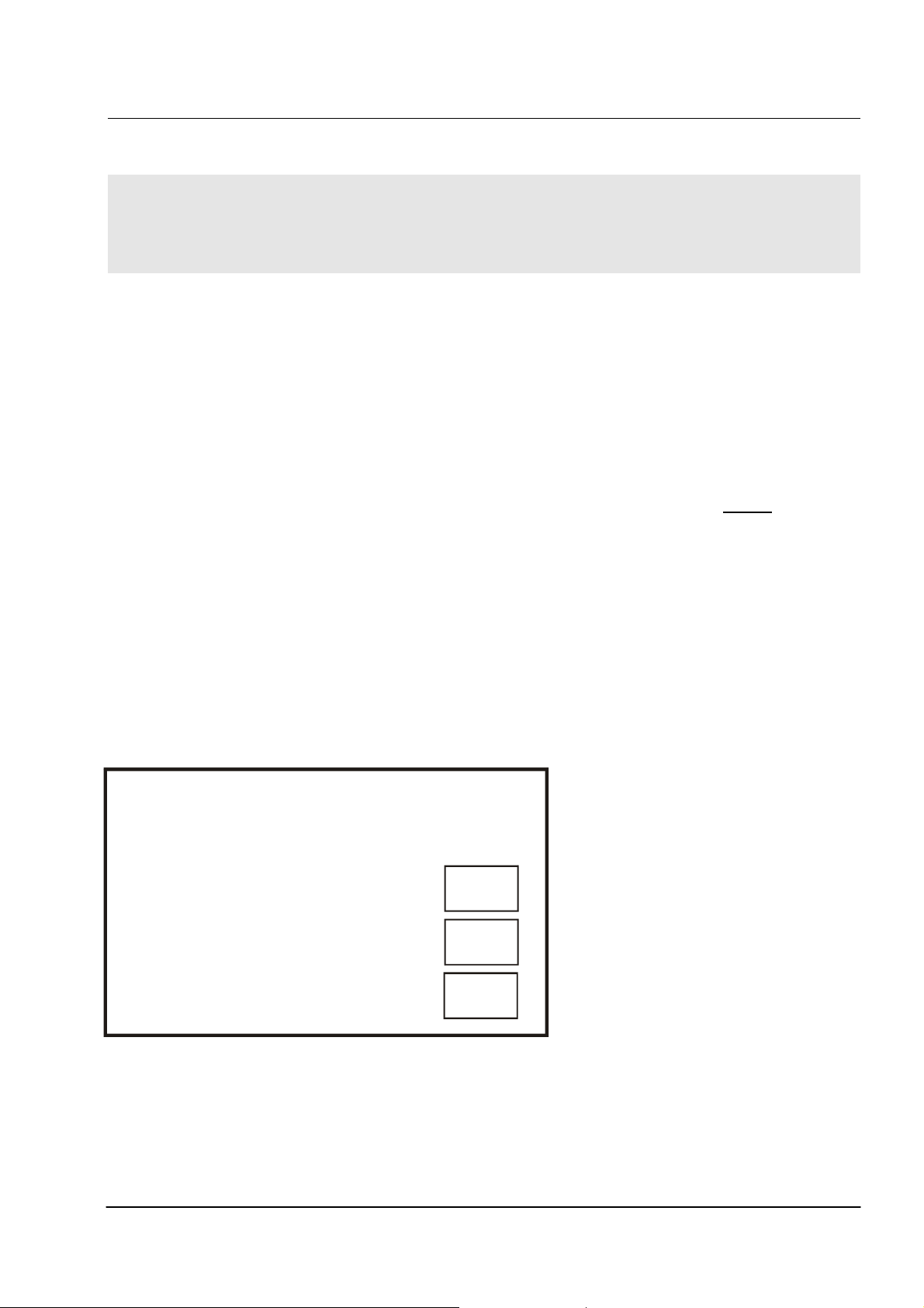
To change the parameters, the corresponding values must be touched. Then, a parameter specific
screen opens where the new parameter values can be typed by touching the figures (except
parameters Output mode, Limit function pH, Limit function Cl2).
AQUACON PH-CL
Calib. factor 1.00
123
Save
4
5
6
78
9
Clear
0
To leave the screen and confirm/safe the new parameter value, the button ”Save” must be touched.
To leave the screen without saving, the button ”Clear” must be touched.
3.6.1 Limit Value 1 pH
Min function:
If the limit function pH is set as min function, the appropriate relay K2 will be activated if the
measured value is lower than the set limit value 1 (LV 1 pH) for this relay. The relay will be
deactivated if the measured value is higher than the set limit value 2 (LV 2 pH) for this relay.
Max function:
If the limit function pH is set as max function, the appropriate relay K2 will be activated if the
measured value is higher than the set limit value 2 (LV 2 pH) for this relay. The relay will be
deactivated if the measured value is lower than the set limit value 1 (LV 1 pH) for this relay.
The limit value 1 pH is set factory-predetermined to 7.20 pH A value between 6.80 and 8.80 may be
chosen, but only values within the measurement range of the analyzer are useful.
3.6.2 Limit Value 2 pH
The limit value 2 pH is set factory-predetermined to 7.60 ppm. A value between 6.80 and 8.80 may be
chosen, but only values within the measurement range of the analyzer are useful.
The set limit value 2 pH must be higher than the set limit value 1 pH.
May 2011
Page 15

AQUACON PH-CL (PC Cabinet)
Technical Information
Page 13
3.6.3 Limit Function pH
The parameter limit function pH defines the function of the limit value relay K2 for the pH analysis. It
can be set to min function or to max function.
This parameter is set factory-predetermined to min. It can be changed by touching the appropriate
field on the touchscreen. No further confirmation is required.
3.6.4 Limit Value 1 Cl2
Min function:
If the limit function Cl2 is set as min function, the appropriate relay K3 will be activated if the
measured value is lower than the set limit value 1 (LV 1 Cl2) for this relay. The relay will be
deactivated if the measured value is higher than the set limit value 2 (LV 2 Cl2) for this relay.
Max function:
If the limit function Cl2 is set as max function, the appropriate relay K3 will be activated if the
measured value is higher than the set limit value 2 (LV 2 Cl2) for this relay. The relay will be
deactivated if the measured value is lower than the set limit value 1 (LV 1 Cl2) for this relay.
The limit value 1 Cl2 is set factory-predetermined to 0.30 ppm. A value between 0.00 and 9.99 may
be chosen, but only values within the measurement range of the analyzer are useful.
3.6.5 Limit Value 2 Cl2
The limit value 2 Cl2 is set factory-predetermined to 0.60 ppm. A value between 0.00 and 9.99 may
be chosen, but only values within the measurement range of the analyzer are useful.
The set limit value 2 Cl2 must be higher than the set limit value 1 Cl2.
3.6.6 Limit Function Cl2
The parameter limit function Cl2 defines the function of the limit value relay K3 for the chlorine
analysis. It can be set to min function or to max function.
This parameter is set factory-predetermined to min. It can be changed by touching the appropriate
field on the touchscreen. No further confirmation is required.
3.6.7 Sampling Intervall
The sampling interval between two automatically initiated samples may be programmed. The factory-
predetermined sample interval is set to 10 min. A values between 1 and 99 min. may be chosen.
May 2011
Page 16

AQUACON PH-CL (PC Cabinet)
Technical Information
Page 14
3.6.8 Titer/Calibration factor
The process photometer AQUACON PH-CL may be re-calibrated by entering a titer/calibration
factor (see chapter 5.5). A value between 0.00 and 9.99 may be chosen.
3.6.9 Rinsing time
The measuring chamber is rinsed for 15 seconds before an analysis takes place. The preset rinsing
time may be altered by the end-user. A value between 15 and 99 seconds may be chosen.
Important:
Depending on the length of the sample inlet tube and the water flow rate, the rinsing time should be
long enough to flush the sample lines and fill the measuring cuvette with fresh sample. A tube
length of max. 5 m is recommended between sample valve and the analyzer.
3.6.10 Reagent Volume
The remaining reagent volume of the reagent 1 is calculated and stored in memory by the
microprocessor. A value between 0 and 999 ml may be chosen.
3.6.11 Analog Output setting (mode)
Two analog current signal (0/4 - 20 mA), proportional to the measured values for pH and for free
chlorine, may be directed from the process photometer AQUACON PH-CL to remote
recording/controlling devices. The mode of both analog outputs can be parametrized by the end-
user. The mode of the analog output can switched from 0-20 mA to 4-20 mA by touching of the
corresponding value on the touchscreen. No further confirmation is required. The start and end
values are fixed and cannot be parametrized. They are set to 0.00 and 8.80 for the pH analysis and
to 0.00 and 2.00 for the chlorine analysis.
The automatic operation mode starts again when the button ”Start” is touched.
May 2011
Page 17
AQUACON PH-CL (PC Cabinet)
Technical Information
Page 15
4 Switching Functions of the AQUACON PH-CL
CAUTION:
Before opening the cover below the process photometer display, the AQUACON PH-CL must
be disconnected from the mains supply.
4.1 External Switching
The process photometer PH-CL has a potential-free input contact which may be used to control the
instrument from a remote position/device. When the input contact is closed the process photometer
will automatically carry out an analysis, when the input contact is open the process photometer
completes the actual analysis and stops. When the limit relay is activated and the process photometer
is stopped by a remote position/device the limit relay will be inactivated after 15 minutes.
The process analyzer is delivered with bridged external switching contact into female. For using
external switching contact remove this bridge! During the interval between two analyses the process
photometer may be activated by a short off/on impulse of the external contact.
4.2 Display in the standby mode
In the standby mode the display will show “H-E” and the last measured value (the value that was
determined in that analysis before that one that was terminated by opening the external contact)
when the external contact is open.
AQUACON PH-CL
State: STANDBY
H - E
pH: 7,40
Start
Cl2: 0,10 ppm
Hand
LV 1 pH: 7.20
LV 2 pH: 7.60
LV 1 Cl2: 0.60
When an error message occurs this will be displayed additional to “H-E”.
4.3 Analysis state relay
The analysis state relay K 1 is activated during the time when the analyzer operates an analysis.
May 2011
LV 2 Cl2: 0.60
Param
Page 18

AQUACON PH-CL (PC Cabinet)
Technical Information
Page 16
4.4 Limit Value Relay K2 and K3
Inside the control unit of the analyzer, there is one limit value relay (K2) for the pH value and one
limit value relay (K3) for the free chlorine. Both relays can be operated in min function mode or in
max function mode. For both relay, 2 limit values (limit value 1 and limit value 2) can be
parametrized.
Min function: If the limit function of the relay K2 or K3 is set as min function, the appropriate relay
will be activated if the measured value is lower than the set limit value 1 for this relay. The relay will
be deactivated if the measured value is higher than the set limit value 2 for this relay.
Max function: If the limit function of the relay K2 or K3 is set as max function, the appropriate relay
will be activated if the measured value is higher than the set limit value 2 for this relay. The relay will
be deactivated if the measured value is lower than the set limit value 1 for this relay.
4.5 Alarm Limit Relay
The potential-free alarm relay is activated when an alarm is exceeded within the process photometer.
The alarm is caused by an error in the optical system, when the measurement range is exceeded or
when the reagent volume falls below than 50 ml. The appropriate alarm message will be displayed as
”ERROR E-1, ERROR E-2, ERROR E-3” or ”ERROR E-4” (see also chapter 6).
4.6 Current Output
The process photometer AQUACON PH-CL delivers a current output, 0 or 4 to 20 mA, which is
proportional to the measurement range selected by the end-user (see chapter 9.1). This current output
may be used as input to remote recording devices, for data processing, controlling functions etc. The
current output is independent of resistance load up to a value of 500 ohm. The start and end value of
the current output signal can be set by the user within the measurement range.
Don’t connect any external voltage to the connections of the current
output. Failure to observe this information could result in damage to the
equipment.
See above, " 3.6.3 Setting the Analog Output". To avoid resolution losses of the current output signal
the user defined measuring range should be > 6 % of the total measurement range. The start value
should be lower than the end value. Setting the start value higher than end value results in a constant
output of 20 mA. Similarly, setting the end value lower than that of the start value results in a constant
0 or 4 mA output.
May 2011
Page 19

AQUACON PH-CL (PC Cabinet)
Technical Information
Page 17
5 Start-up and Maintenance Instructions
CAUTION:
As soon as the analyzer is connected to the main supply, automatic operation commences. This is
required for automatic restart of the analyzer in the event of a power failure. At start-up, it is
necessary to access the Manual Operating mode by touching the ”Hand” button as soon as the
analyzer is connected to main supply and is operational.
5.1 Connection of sample water
1. Connect inlet and outlet connectors (6/4; 8/6) max. length 5 m
2. Connect power supply to device
Caution: see label on the housing for specified voltage
3. Select the sample inlet valve to “open” (press button on the touchscreen)
4. Carefully open the manually-operated valve beneath the solenoid operated valve to set the
sample flow (20-30 l/h)
Caution: Maximum sample pressure 10 bar!
5.2 Connection of reagent, bleeding of pumps and tubes
1. Open the reagent vessel top.Ensure that the pump tube is installed and the pump head is screwed
down.
2. Switch on the stirrer (button ) and the first pump (button ) in order to fill the suction-
lances and pressure-tubes (Sign:the extinction in the display is rising).
3. After filling the tubes switch off the pump and stirrer.
4. If there is a second or third reagent avaible, repeat step 1-3 with this reagents.
5. Rinse the measuring chamber by activating the sample inlet valve (button ) and stirrer
(button ) in order to wash out the reagent entered while filling the tubes
6. Select automatic operation (button ). The device now operates in automatic mode and start
the measurement.
Perform 2 to 3 analyses. Regard correct filling by observing the measurement outlet tube with
the selected sample flow conditions. When satisfied that the system is performing correctly,
the parameter settings may be carried out prior to automatic operation
5.3 Replenishment of Reagent
The reagent bottle may be replaced, after setting the analyzer to manual mode. Now the volume of
reagent must be entered in “Param” mode step to 250 (if the volume of reagent 1 is 250 ml) or to
500 (if the volume of reagent 1 is 500 ml). See also chapter 3.6.7.
Important:
The handling with chemical standards and reagents can be dangerous. Before the reagent bottles are
connected or replaced, it is necessary to read their specific MSDS (material safety data sheets).
May 2011
Page 20

AQUACON PH-CL (PC Cabinet)
Technical Information
Page 18
5.4 Changing of Tube box
Replacement of the complete tube-box by pressing the brackets at the sides,take off the old box and
give up a new box.
Important:
All tube boxes must be replaced after consumption of 5 bottles reagent or latest after 6
months.
5.5 Recalibration of the Process analyzer
Under normal conditions, a re-calibration of the process analyzer is not required since the reagent to
sample ratio have been correctly determined at the time of manufacture. However should the need
arise to verify the process analyzer, a standard solution may be introduced. In the unlikely event of a
deviation from the introduced standard (incorrect reagent strength, pump tube aging, incorrect pump
tube, contaminated measuring cell), a titer/calibration factor may be calculated as follows:
titer/calibration factor = Standard solution value : Measured value
Should the titer/calibration factor deviate by more than 20 % from 1, then a change of the tube box
or a cleaning of the measurement chamber is maybe necessary.
5.6 Maintenance interval
A maintenance of the analyzer should be made after 5 consumed reagent bottles or latest after 6
month. A maintenance should include at least an optical control of the analyser, a function control
and a change of the tube boxes. If necessary, the maintenance should also include a cleaning of the
measurement chamber and of the injectors for the tube connection at the measurement chamber.
5.7 Shut down procedure
If the analyzer is shut down for an extended period of time, all reagents and samples should be
removed out of tubings and the measurement chamber, and all tubings and the measurement
chamber should be cleaned and flushed with deionized water.
May 2011
Page 21

AQUACON PH-CL (PC Cabinet)
Technical Information
Page 19
6 Alarm Messages
Message in
Description ACTION
display
ERROR E -1
Error in the optical system; the
analyzer operation is interrupted:
- contaminated cuvette windows
- defective light source
- defective photodetector
- no sample (NB Most likely cause of
failure!)
ERROR E -2 Measurement range exceeded
ERROR E - 3 Reagent volume has dropped below
the factory preset value of 50 ml. The
operation of the analyzer remains
unaffected until reagent is depleted.
ERROR E - 4 Reagent depleted. The analyzer results
are no longer valid.
H -E Remote operation activated
Check sample inlet valve, clean
the measuring chamber, call
maintenance service.
Verify if chlorine concentration
or pH value is too high. Check
stirrer function.
Replace reagent soon.
Replace reagent.
7 Technical Data
Current output 2 x 0/4 - 20 mA, max. load 500 ohm
Display 240 x 128 dots, Touchscreen
Relays
External Switching potential-free contact, 18 V DC, ca. 4 mA
Power Supply 110 - 230 V -- 50/ 60 Hz
Power Consumption approx. 16 VA
Dimensions 640 x 315 x 190 mm (H x W x D)
Protection IP 65 (transmitter housing)
Connections Plugs with circular connection 1,5 mm
Temperature 5° to 45°C, at consumption of reagents within 6 months
Since it is company policy to continuously improve its product range, we reserve the right to
make changes in the product design without notification to its users
1 x Alarm relay, potential-free 230 V/50 Hz, 3A
2 x Limit relay, potential-free 230 V/50 Hz, 3A
1 x Analysis state relay, potential-free 230 V/50 Hz, 3A
2
May 2011
Page 22

AQUACON PH-CL (PC Cabinet)
Technical Information
Page 20
8 Specifications
Parameter pH value and free chlorine
Description
Typical Applications
Method of working
Measuring Range
Resolution
Accuracy
Reproducibility
Zero-point Stability
Number of samples
Sample
Operating Pressure
Temperature
Sample Volume
Sample Condition
Chemical Demands
Drain
Reagents
Number
Storage Temperature
Usage/analysis
Reagent volume
Suitable for analysis
Analysis
Cycle (approx.)
Sample interval
Automatic microprocessor controlled analyser for the photometric
determination of pH value and free chlorine in water
AQUACON PH-CL
Control and supervision of chlorine plants and swimming pools
Photometric measurement of free chlorine (DPD method)
Photometric measurement of the pH value with indicator
pH: 6,80 – 8,80
Cl2: 0,02 – 2,00 ppm
0,01 pH
0,01 ppm
2 % of end value (Cl2)
+/- 0,2 pH
1 % of end value (Cl2)
+/- 0,05 pH
automatic readjustment
1
0,1 - 10 bar
5 - 30 °C
25 ml per analysis (without rinsing volume)
clear, filtrated
pH 6,80 – 8,80
without pressure
3
5 – 25 °C (avoid light)
appr. 0,54 ml / 0,27 ml / 0,27 ml
500 / 250 / 250 ml
appr. 925
3 min (excl. rinsing time)
1 min - 99 min
9 Connection Diagram
9.1 Set 0/4 - 20 mA-Output
The 0/4 – 20 mA output can be set by changing the appropriate parameters (see chapter 3.6.3).
May 2011
Page 23
AQUACON PH-CL (PC Cabinet)
Technical Information
Page 21
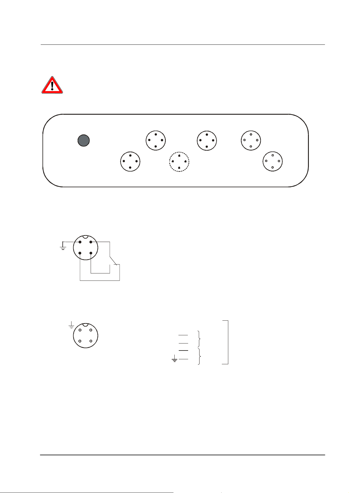
9.2 Connections
In – and outputs are available at circular connectors at the top of the device.
CAUTION: technical data !
power supply
(Male)
PE
3
K2
K1 K3 option
1
2
K1 / K2 / alarm
alarm external start
0/4-20 mA recorder
(Female)
1
3
Power supply Power supply (110 - 230 V, 50/60 Hz) PE protection earth
K1 Analysis status signal K2 Limit value relay 1(for pH value)
external start potential-free input contact alarm Alarm limit relay
20 mA recorder 1
20 mA recorder 2
2
0/4 – 20 mA output (max. load 500 Ω)
0/4 – 20 mA output (max. load 500 Ω)
external start: pin 1 / 2
recorder 1 : pin 1
pin 2
recorder 2 : pin 3
(optional)
pin
caution !
+
20 mA
+
20 mA
-
K3 Limit value relay 2 (for Cl2)
do not connect any voltage
to these terminals
May 2011
Page 24
AQUACON PH-CL (PC Cabinet)
Technical Information
Page 22
9.3 Installation
WARNING
Only Qualified Personnel !
Only Specified Power Supply !
See required power supply as noted on instrument.
Observe local regulations!
Install a power supply that can be disconnected (plug, switch).
Take care for use of the protective covers for not used connectors.
Do not install measuring-or control cables in parallel or close distance in the same cable guide with
power supply.
May 2011
Page 25
AQUACON PH-CL (PC Cabinet)
Technical Information
Page 23
10 Appendix
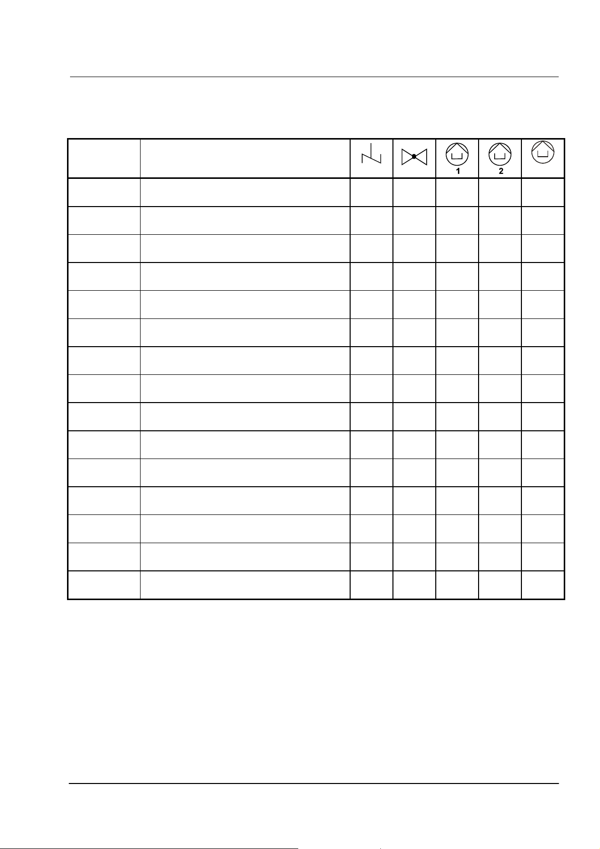
10.1 Analysis cycle AQUACON PH-CL
Length Operation
15 -99 s Rinsing X
10 s Degasification X
~ 40 s Automatic zero adjustment
2 s Dosing of Reagent 1 X X
15 s Stirring X
10 s Measurement pH value
35 Rinsing X
10 s Degasification X
~ 40 s Automatic zero adjustment
1 s Dosing of Reagent 2 X X
3
1 s Dosing of Reagent 3 X X
3 s Mixing X
10 s Measurement free chlorine
20 s Rinsing X X
1 - 99 min. Break time
May 2011
Page 26
AQUACON PH-CL (PC Cabinet)
Technical Information
Page 24
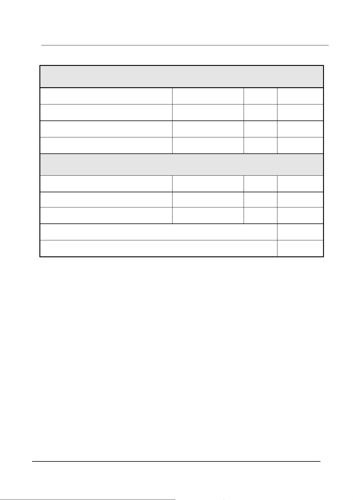
10.2 Spare part and consumable item list
Consumable item Term Quantity Order No
Reagent 1 for AQUACON PH-CL PH80 500 ml 101 3180 01
Reagent 2 for AQUACON PH-CL CL-R1001 250 ml 101 2725 01
Reagent 3 for AQUACON CHLOR CL-R1002 250 ml 102 2725 01
Tube - box SK10 1 piece 121 0037 01
Spare parts Order No
Transmission pressure tubing PT10 1 m 121 0014 01
Tube pump SP10-2 1 piece 121 0008 02
Magnetic valve type 1 2/2 way (brass)
Magnetic stirring bar for measuring chamber 121 0044 01
Glass measuring cuvette 121 0045 01
Basic equipment of consumables are included in price
MV01-G 1 piece 121 0004 02
May 2011
Page 27

AQUACON PH-CL (PC Cabinet)
Technical Information
Page 25
11 Troubleshooting Guide
Problem Reason
On pressing the “automatic
operation” key switch, the analyzer
does not enter automatic analysis
cycle.
The analyzer continuously displays
setpoint overrange
The values displayed are erratic
even though the actual measured
variable is constant
A calibration factor differing
widely from 1.00 must be used to
achieve correct results
Pumps or solenoid operated valves
do not operate in manual mode
• The contact bridge for external switch function (see 4.1) is not installed or
has no contact switch.
“H-E” appears in the display.
Solution: install bridge
• The measurement chamber is empty (i.e. no sample) or the sample is strongly
coloured or contaminated.
“ERROR E-1” appears in the display. The analyzer will automatically reenter the measurement cycle following the sample interval and reset the
alarm
Solution: clean the measurement cuvette with 10% hydrochloric acid, check
sample flow, check optical components (open measurement chamber and set
analyzer to manual operation. The displayed absorption should increase
when the optical path is restricted by an opaque object)
• Reagent is depleted or incorrect reagent volume entered.
“ERROR E-4” appears in the display.
Solution: Replace reagent if depleted and reset reagent volume to the correct
volume via parameter input..
• The setpoint selected is below the measured value.
“ERROR E-2” appears in the display.
Solution: Verify the measured value by alternative analysis
Increase setpoint value
• Reagent container is not opened to atmosphere.
Vacuum drawn on the reagent vessel.
Solution: Open the reagent bottle cap to release vacuum. Do not retighten.
• Magnetic stirrer immobilised
Solution: Open the measurement cuvette. Stirrer is switched on by manual
operation. Check that the magnetic follower is not jammed by loosening
gently with a glass stirring rod.
Increase the motor voltage by adjusting the appropriate potentiometer in the
terminal box.
If the problem is not rectified, call Service.
• Reagent tubing is kinked or the feed tube in the reagent container is pushed
against the bottom of the vessel.
Solution: Straighten all tubes and tilt feed tube away from the bottom of the
reagent container
• Sample pressure is too low to effectively flush the measuring cuvette after
analysis
The cuvette does not overflow or overflows very slowly during flushing
cycle.
Solution: Increase the sample pressure to above 0.1 bar.
Open sample inlet valve to allow 100 - 200 ml water flow per analysis cycle..
• Reagent is contaminated, reagent has expired, pump tube has exceeded.
Solution: replace reagent; replace pump tubing.
• a limited number of electromechanical drives may be simultaneously selected
to prevent electrical overload.
Solution: Switch off other electromechanical drives and try again.
May 2011
 Loading...