

Page 1
Serial488A, Serial488A/OEM, Serial488A/512K
User’s Manual
IOtech, Inc.
25971 Cannon Road
Cleveland, OH 44146
Phone: (440) 439-4091
Fax: (440) 439-4093
E-mail: sales@iotech.com
Internet: http://www.iotech.com
Serial488A, Serial488A/OEM,
Serial488/512K User’s Manual
p/n
SERIAL488/A-901, Rev 2.3
© 1998 by IOtech, Inc. — Printed in the United States of America
Page 2
Warranty
Your IOtech warranty is as stated on the product warranty card. You may contact IOtech by
phone, fax machine, or e-mail in regard to warranty-related issues.
Phone: (440) 439-4091, fax: (440) 439-4093, email:
sales@iotech.com
Limitation of Liability
IOtech, Inc. cannot be held liable for any damages resulting from the use or misuse of this
product.
Copyright, Trademark, and Licensing Notic e
All IOtech documentation, software, and hardware are copyright with all rights reserved. No
part of this product may be copied, reproduced or transmitted by any mechanical,
photographic, electronic, or other method without IOtech’s prior written consent. IOtech
product names are trademarked; other product names, as applicable, are trademarks of their
respective holders. All supplied IOtech software (including miscellaneous support files,
drivers, and sample programs) may only be used on one installation. You may make archival
backup copies.
FCC Statement
IOtech devices emit radio frequency energy in levels compliant with Federal Communications
Commission rules (Part 15) for Class A devices. If necessary, refer to the FCC booklet How To Identify
and Resolve Radio-TV Interference Problems (stock # 004-000-00345-4) which is available from the
U.S. Government Printing Office, Washington, D.C. 20402.
CE Notice
Many IOtech products carry the CE marker indicating they comply with the safety and emissions
standards of the European Community. As applicable, we ship these products with a Declaration of
Conformity stating which specifications and operating conditions apply.
Warnings and Cautions
Refer all service to qualified personnel. This caution symbol warns of possible personal injury or
equipment damage under noted conditions. Follow all safety standards of professional practice and the
recommendations in this manual. Using this equipment in ways other than described in this manual can
present serious safety hazards or cause equipment damage.
This warning symbol is used in this manual or on the equipment to warn of possible injury or death from
electrical shock under noted conditions.
This ESD caution symbol urges proper handling of equipment or components sensitive to damage from
electrostatic discharge. Proper handling guidelines include the use of grounded anti-static mats and wrist
straps, ESD-protective bags and cartons, and related procedures.
Specifications and Calibration
Specifications are subject to change without notice. Significant changes will be
addressed in an addendum or revision to the manual.
hardware products to published specifications. Periodic hardware calibration is not covered
under the warranty and must be performed by qualified personnel as specified in this manual.
Improper calibration procedures may void the warranty.
As applicable, IOtech calibrates its
Quality Notice
IOtech has maintained ISO 9001 certification since 1996. Prior to shipment, we thoroughly test our
products and review our documentation to assure the highest quality in all aspects. In a spirit of
continuous improvement, IOtech welcomes your suggestions.
Page 3

Introduction
1.1 Description
The
Serial488A, Serial488A/OEM
provide transparent communication from a serial computer to an IEEE 488 printer,
plotter or other device. They also can be used to control a serial device, such as a
printer or terminal, from an IEEE 488 host computer.
As a serial to IEEE 488 converter, it receives data from a serial host then
automatically performs the bus seq uences necessary to send this data to t he IEEE 488
device. If desired, data can be requested from the IEEE 488 device and returned to the
host.
As an IEEE 488 to serial converter, it functions as a peripheral to an IEEE 488
controller. Data received from the controller is sent to the serial device, and data
received from the serial device is buffered for transmission to the IEEE 488 controller.
The converter can inform the host, by the serial poll status byte, that it has received
data from the serial device.
The
Serial488A
422 devices by positioning configuration jumpers located within the unit. Both
devices can communicate at selectable baud rates up to 57600 baud.
and
Serial488A/OEM
and
Serial488/512K
can communicate with RS-232 and RS-
Bus Converters
The
Serial488/512K
rates up to 19200 baud.
This manual will refer to all three interfaces as the
between the
applicable.
Serial488A, Serial488A/OEM
can communicate with RS-232 devices at selectable baud
. Differences
and
Serial488/512K
Serial488A
will be noted where
1.1
Page 4

1.2 Serial488 and Serial488A Differences
The
Serial488A
is both a hardware and firmware upgrade to the
Serial488
When issuing product improvements, we try to maintain transparent compatibility.
Occasionally this is not possible. You should note the following differences between
the two products.
1. The
Serial488
characters. The
allocated fixed serial and IEEE input buffers of 4000
Serial488A
utilizes a 32,000 character buffer which is
dynamically allocated to the serial and IEEE input buffers as required.
Refer to Section 4.2 for more details
2. The
Serial488A
has the ability to output RS-232 or RS-422 levels. The
levels used are internally selectable. Refer to Section 2.8 for details.
3. As a peripheral, the
Serial488A
's serial poll status byte has been
changed to include status of the serial handshake. Other minor changes
have also been included. Refer to Section 4.4 for a complete description
of the serial poll status byte.
4. The internal switch settings for baud rate have been adjusted to include
57600 baud. Refer to Section 2.3 for the new switch settings.
.
1.3 Serial488A, Serial488A/OEM and Serial488/512K Differences
1. The
Serial488A
and
Serial488A/OEM
utilize a 32,000 character buffer
which is dynamically allocated to the serial and IEEE input buffers as required. The
Serial488/512K
utilizes a 512,000 character buffer which is dynamically allocated to
the serial and IEEE input buffers as required.
2. The
RS-422 levels. The
3. The
Serial488A
Serial488/512K
Serial488A
up to 57600 baud. The
and
Serial488A/OEM
can only operate at RS-232 levels.
and
Serial488A/OEM
Serial488/512K
have the ability to output RS-232 or
can operate at selectable baud rates
can operate at selectable baud rates up to
19200 baud.
1.2
Page 5

1.4 Available Accessories
Additional accessories that can be ordered for the
CA-7-1
CA-7-2
CA-7-3
CA-7-4
CA-11
CA-21
CA-22
CA-23
CN-20
CN-22
CN-23
ABC488
Rack488-3
Rack488-4
140-0920
Serial488A
include:
1.5 foot IEEE 488 Cable
6 foot IEEE 488 Cable
6 foot shielded IEEE 488 Cable
6 foot reverse entry IEEE 488 Cable
12 foot IBM PC/XT/PS2 to Serial488A RS-232 Cable
12 foot Macintosh II/SE/Plus to Serial488A RS-232 Cable
12 foot Macintosh 512K to Serial488A RS-232 Cable
12 foot IBM AT to Serial488A RS-232 Cable
Right Angle IEEE 488 adapter, male and female
IEEE 488 Multi-tap bus strip, four female connectors in parallel
IEEE 488 panel mount feed-through connector, male and female
IEEE 488 ABC switch
5-1/4" by 19" rack mount for one
5-1/4" by 19" rack mount for two
Serial488A
Serial488A
s
Instruction Manual
1.3
Page 6
Specifications
Do not use this interface outdoors! The interface is intended for indoor use only! Outdoor
conditions could result in equipment failure, bodily injury or death!
If equipment is used in any manner not specified in this manual, the protection provided by the
equipment may be impaired. Please read this manual carefully.
Do not connect AC line power directly to the Serial488A. Direct AC connection will damage the
equipment.
Serial488A
:$51,1*
:$51,1*
&$87,21
IEEE 488
&$87,21
The IEEE 488 terminal must only be used to control a non-isolated IEEE 488 system. The
common mode voltage (cable shell to earth) must be zero.
Terminal Installation Category:
Standard: Not Applicable CE: Category 1
Implementation: C1, C2, C3, C4 and C28 controller subsets.(Serial to IEEE)
SH1, AH1, T6, TE0, L4, LE0, SR1, RL0, PP0, DC1, DT0, E1.
Terminators: Selectable CR, LF, LF-CR and CR-LF with EOI.
Connector: Standard IEEE 488 connector with metric studs.
Serial Interface
Terminal Installation Category:
Standard: Not Applicable CE: Category 1
EIA RS-232C: AB, BA, BB, CA, CB
EIA RS-422A: Balanced voltage on TxD and RxD.
Character Set: Asynchronous bit serial.
Output Voltage: ±5 volts min (RS-422A). 5 volts typical (RS-232C).
Input Voltage: ±3 volts min.; ±15v max.
Baud Rate: Selectable 110, 300, 600, 1200, 1800, 2400, 3600, 4800, 7200,
9600, 19,200 and 57,600.
1.4
Page 7

Data Format: Selectable 7 or 8 data bits; 1 or 2 stop bits; odd, even, mark,
space and no parity on transmit.
Duplex: Full with Echo/No Echo.
Serial Control: Selectable CTS/RTS or XON/XOFF.
Terminators: Selectable CR, LF, LF-CR and CR-LF.
Connector: 25-pin Sub-D male. DCE Configured.
General
Terminal Installation Category:
Standard: Not Applicable
CE: Category 1 for all terminals.
Data Buffer: 32,000 characters dynamically allocated.
Indicators: LEDs for IEEE Talk and Listen, Serial Send and Receive, and
Power.
Power: An external power supply is provided with the Serial488A.
Input is 105 to 125VAC; 50 to 60 Hz, 10 VA Maximum.
Dimensions: 188mm deep x 140mm wide x 68mm high (7.39" x 5.5" x
2.68").
Weight: 1.55 kg. (3.6 lbs).
Operating Environment:
Standard: Indoor use, 0° to 50°C; 0 to 70% R.H. to 35°C.
Linearly derate 3% R.H./°C from 35° to 50°C.
CE: Indoor use at altitudes below 2000m, 0° to 40°C; 80% maximum
RH up to 31°C decreasing linearly 4% RH/°C to 40°C.
Controls: Power Switch (external), IEEE and Serial parameter switches
(internal). Jumper selection of RS-232 or RS-422 operation
(internal).
*Specifications subject to change without notice
1.5
.
Page 8

Serial488A/OEM
IEEE 488
Implementation: C1, C2, C3, C4 and C28 controller subsets.(Serial to IEEE)
SH1, AH1, T6, TE0, L4, LE0, SR1, RL0, PP0, DC1, DT0, E1.
Terminators: Selectable CR, LF, LF-CR and CR-LF with EOI.
Connector: Standard IEEE 488 connector with metric studs.
Serial Interface
EIA RS-232C: AB, BA, BB, CA, CB
EIA RS-422A: Balanced voltage on TxD and RxD.
Character Set: Asynchronous bit serial.
Output Voltage: ±5 volts min (RS-422A). 5 volts typical (RS-232C).
Input Voltage: ±3 volts min.; ±15v max.
Baud Rate: Selectable 110, 300, 600, 1200, 1800, 2400, 3600, 4800, 7200,
9600, 19,200 and 57,600.
Data Format: Selectable 7 or 8 data bits; 1 or 2 stop bits; odd, even, mark,
space and no parity on transmit.
Duplex: Full with Echo/No Echo.
Serial Control: Selectable CTS/RTS or XON/XOFF.
Terminators: Selectable CR, LF, LF-CR and CR-LF.
Connector: 25-pin Sub-D male. DCE Configured.
General
Data Buffer: 32,000 characters dynamically allocated.
Indicators: LEDs for IEEE Talk and Listen, Serial Send and Receive, and
Power.
Power: User supplied +5 volts ±0.25% at 1 amp. Mating power
connector with 8 inch leads provided.
Dimensions: 205mm deep x 115mm wide x 28mm high (8" x 4.5" x 1.1").
Weight: 0.23kg. (0.5 lbs.)
Environment: 0° - 50°C; 0 to 70% R.H. to 35°C. Linearly derate
3% R.H./°C from 35° to 50°C.
Controls: IEEE and Serial parameter switches. Jumper selection of
RS-232 or RS-422 operation.
*Specifications subject to change without notice
.
1.6
Page 9

Serial488/512K
IEEE 488-1978
Implementation: C1, C2, C3, C4 and C28 controller subsets.(Serial to IEEE)
SH1, AH1, T6, TE0, L4, LE0, SR1, RL0, PP0, DC1, DT0, E1.
Terminators: Selectable CR, LF, LF-CR and CR-LF with EOI.
Connector: Standard IEEE 488 connector with metric studs.
Serial Interface.
EIA RS-232C: AB, BA, BB, CA, CB
Character Set: Asynchronous bit serial.
Output Voltage: 5 volts typical (RS-232C).
Input Voltage: ±3 volts min.; ±15v max.
Baud Rate: Selectable 110, 300, 600, 1200, 1800, 2400, 3600, 4800, 7200,
9600, and 19,200.
Data Format: Selectable 7 or 8 data bits; 1 or 2 stop bits; odd, even, mark,
space and no parity on transmit.
Duplex: Full with Echo/No Echo.
Serial Control: Selectable CTS/RTS or XON/XOFF.
Terminators: Selectable CR, LF, LF-CR and CR-LF.
Connector: 25-pin Sub-D male. DCE Configured.
General
Data Buffer: 512,000 characters.
Indicators: LEDs for IEEE Talk and Listen, Serial Send and Receive, and
Power.
Power: 105-125V or 210-250V; 50-60 Hz, 10 VA Max.
Dimensions: 188mm deep x 140mm wide x 68mm high (7.39" x 5.5" x
2.68").
Weight: 1.95 kg. (4.35 lbs).
Environment: 0° - 50°C; 0 to 70% R.H. to 35°C. Linearly derate
3% R.H./°C from 35° to 50°C.
Controls: Power Sw itch (external)
IEEE and Serial parameter switches (internal).
*Specifications subject to change without notice
.
1.7
Page 10

1.6 Abbreviations
The following IEEE 488 abbreviations are used throughout this manual.
addr n IEEE bus address "n"
ATN Attention line
CA Controller Active
CO Controller
CR Carriage Return
data Data String
DCL Device Clear
GET Group Execute Trigger
GTL Go To Local
LA Listener Active
LAG Listen Address Group
LF Line Feed
LLO Local Lock Out
MLA My Listen Address
MTA My Talk Address
PE Peripheral
PPC Parallel Poll Configure
PPU Parallel Poll Unconfigure
SC System Controller
SDC Selected Device Clear
SPD Serial Poll Disable
SPE Serial Poll Enable
SRQ Service Request
TA Talker Active
TAD Talker Address
TCT Take Control
term Terminator
UNL Unlisten
UNT Untalk
* Unasserted
1.8
Page 11

Getting Started
2.1 Inspection
The
Serial488A
prior to shipment. When you receive the interface, carefully unpack all items from the
shipping carton and check for any obvious signs of physical damage which may have
occurred during shipment. Immediately report any such damage found to the shipping
agent. Remember to retain all shipping materials in the event that shipment back to
the factory becomes necessary.
Every
Every
Serial488A
•
Serial488A
•
140-0920
•
Power Supply
Serial488A/OEM
was carefully inspected, both mechanically and electrically,
is shipped with the following....
IEEE 488 Bus Converter
Instruction Manual
9 Volt Regulated
TR-2; 115V or
TR-2E; 220V
is shipped with the following....
Every
•
Serial488A/OEM
•
140-0920
Serial488/512K
•
Serial488/512K
•
140-0920
•
Power Supply
IEEE 488 Bus Converter
Instruction Manual
is shipped with the following....
IEEE 488 Bus Converter
Instruction Manual
9 Volt Regulated
TR-2; 115V or
TR-2E; 220V
2.1
Page 12

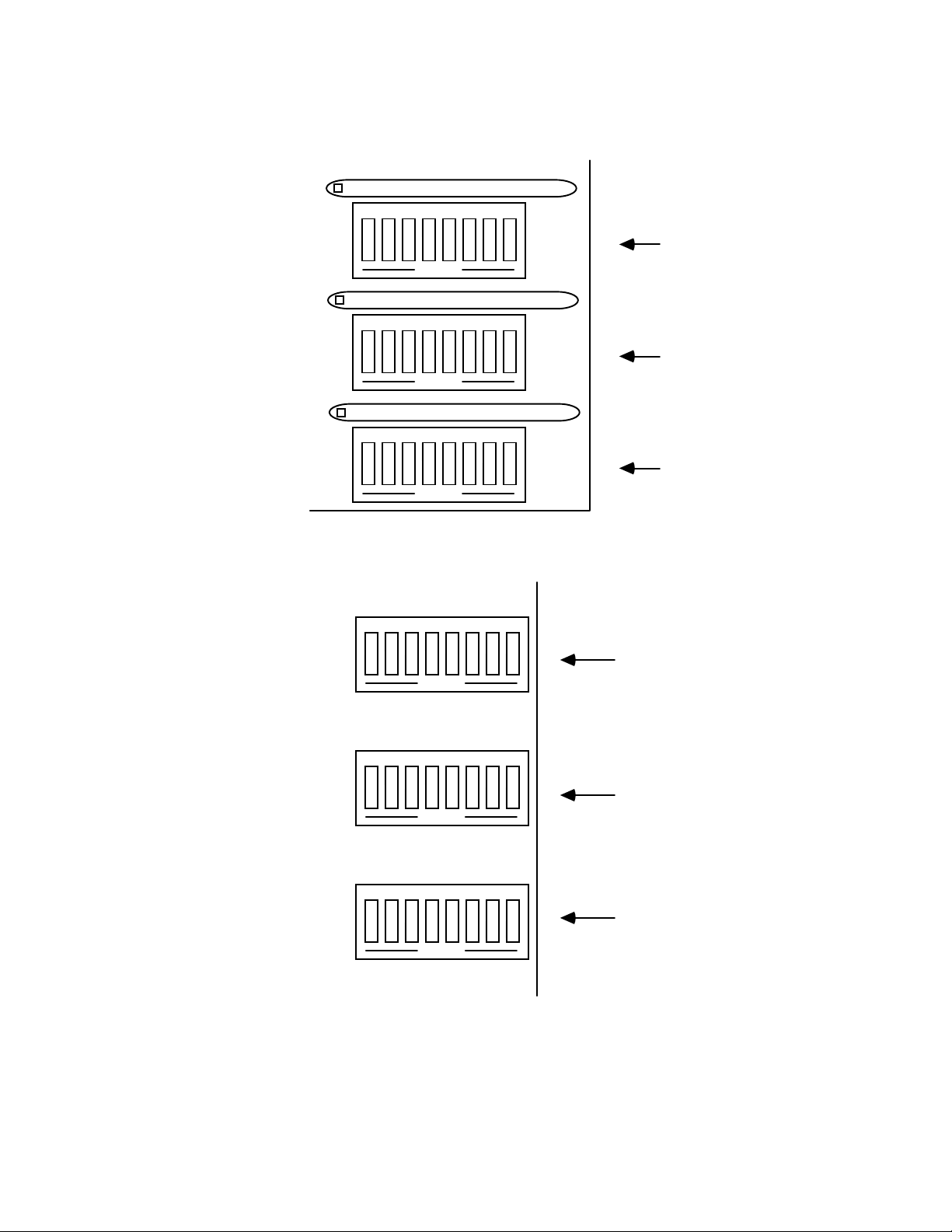
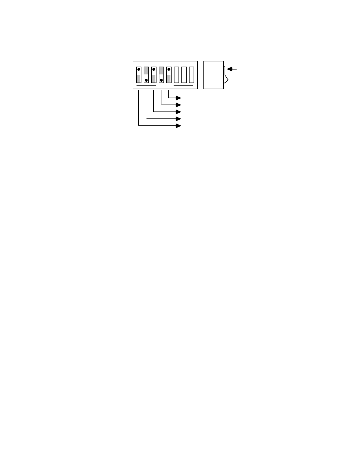
2.2 Configuration
Three DIP switches internal to the
Serial488A
set the configuration of the
interface. NOTE: Selectable functions are read ONLY at power-on and should only
be set prior to applying power to the interface. The following figures illustrate the
factory default settings which are:
Serial Port: IEEE:
9600 Baud Mode = IEEE 488 Controller
8 Data Bits Address = 10
2 Stop Bits Bus Terminator = LF; EOI Disabled
No Parity Talk-back on Terminator Enabled
Serial Terminator = LF Talk-back on Time Out Enabled
Echo Disabled
RTS/CTS Handshake
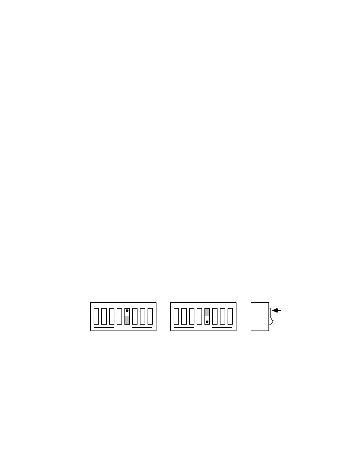
SW3 Factory Default Settings
IEEE Addr
IEEE Term
EOI
12345678
SW3
OPEN
10
LF
Disabled
Switch
DOT
Side
View
2.2
Page 13
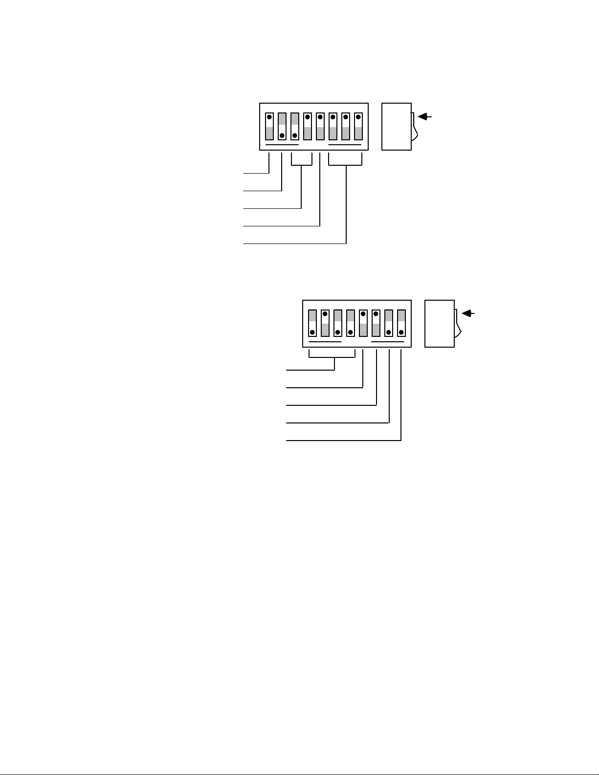
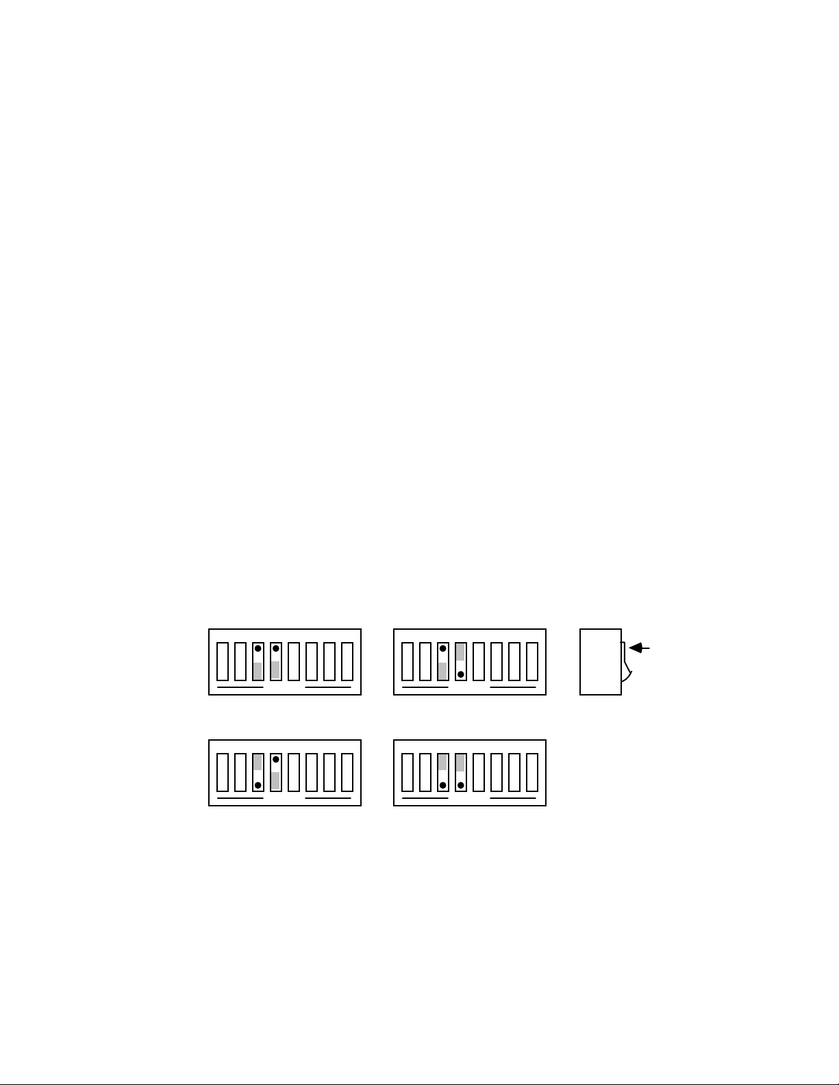
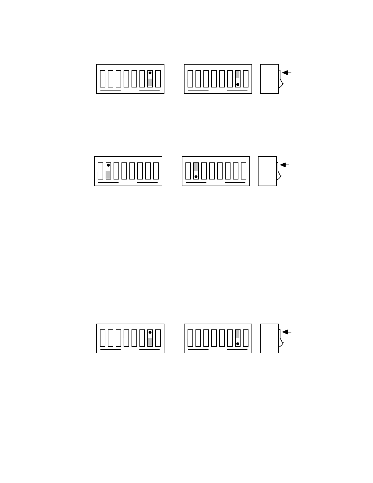
SW2 Factory Default Settings
Mode
Talk Back on Time Out
Serial Term
Echo
Parity
Handshake
Word Length
Talk Back on Term
12345678
SW2
OPEN
C
Enabled
LF
No Echo
No Parity
SW1 Factory Default Settings
12345678
Baud Rate
Stop Bits
SW1
9600
RTS/CTS
8 Data Bits
Enabled
2 Stop Bits
OPEN
Switch
DOT
Side
View
DOT
Switch
Side
View
The following drawings show the locations of switches SW1, SW2, and SW3 for
the
Serial488A, Serial488A/OEM
the
Serial488A
and the
Serial488/512K
and the
Serial488/512K
is referred to as the I/O board.
2.3
. The top circuit board in
Page 14
Serial488A Switch Location - I/O Board
12345678
OPEN
12345678
OPEN
12345678
S203
SW2 SW3
S202
SW3
SW2
SW1
OPEN
S201
Serial488A/OEM Switch Location
S101
12345678
SW1
OPEN
SW-6-8
S102
12345678
SW2
OPEN
SW-6-8
S103
12345678
SW3
SW1
OPEN
SW-6-8
2.4
Page 15

Serial488/512K SW1, SW2 Location - I/O Board
12345678
SW2
SW-6-8
12345678
OPEN
IC-39
74HCT244
C-5-.1
RN-1-10K
SW1
OPEN
SW-6-8
Serial488/512K SW3 Location - Motherboard
12345678
OPEN
SW3
S102
2.5
Page 16

Note that the
the
Serial488A
Serial488A
is designed to allow an RS-232 computer to communicate with an
comes configured as an IEEE controller. In t his mod e
IEEE peripheral such as a plotter. This controller mode is described in detail in
Section 3
.
The
Serial488A
peripheral, the
Serial488A
device. The peripheral mode of operation is described in detail in
may also be configured as an IEEE peripheral. As an IEEE
allows an IEEE controller to commun icate with an RS-232
Section 4
.
To modify any of these defaults, follow this simple procedure: Disconnect the
power supply from the AC line and from the interface. Disconnect any IEEE or serial
cables prior to disassembly.
WARNING
Never open the Serial488A case while it is
connected to the AC line. Failure to observe this
warning may result in equipment failure,
personal injury or death.
Place the interface upside down on a flat surface. Remove the four (4) screws
located near the rubber feet. Return the interface to the upright position and carefully
remove the top cover. Modify those parameters which are appropriate for your
installation and then carefully re-assemble the interface using the reverse of the
procedure described.
2.3 Serial Port Settings
The first parameters to configure are those that correspond to the RS-232 port.
These include baud rate, word length, number of stop bits, parity selection and type of
RS-232 handshake. Each of these are described in the following sections.
2.3.1 Serial Baud Rate Selection
Baud rate defines the number of serial bits per second transferred into
and out of the RS-232 interface. SW1-1 through SW1-4 determine the
serial baud rate. The factory default baud rate is 9600 baud. Baud rates
may be selected from 110 to 57600 baud (110 to 19200 for the
Serial488/512K
).
2.6
Page 17
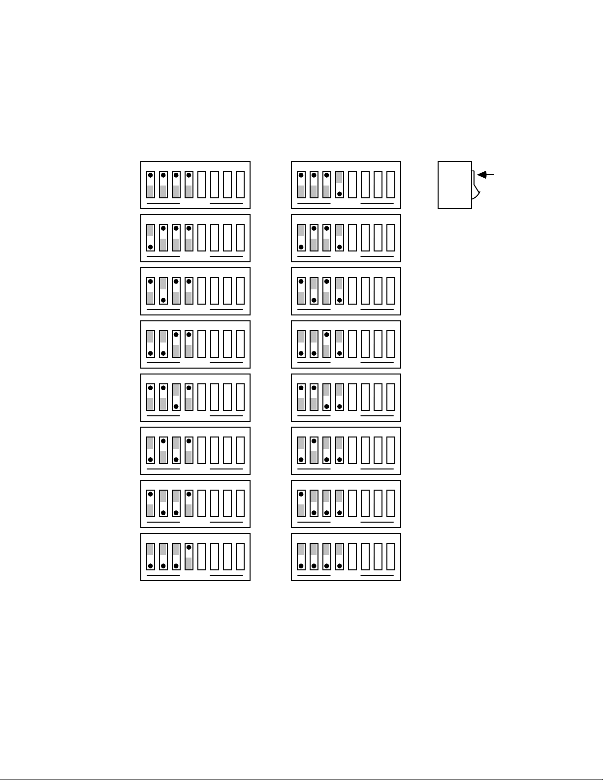
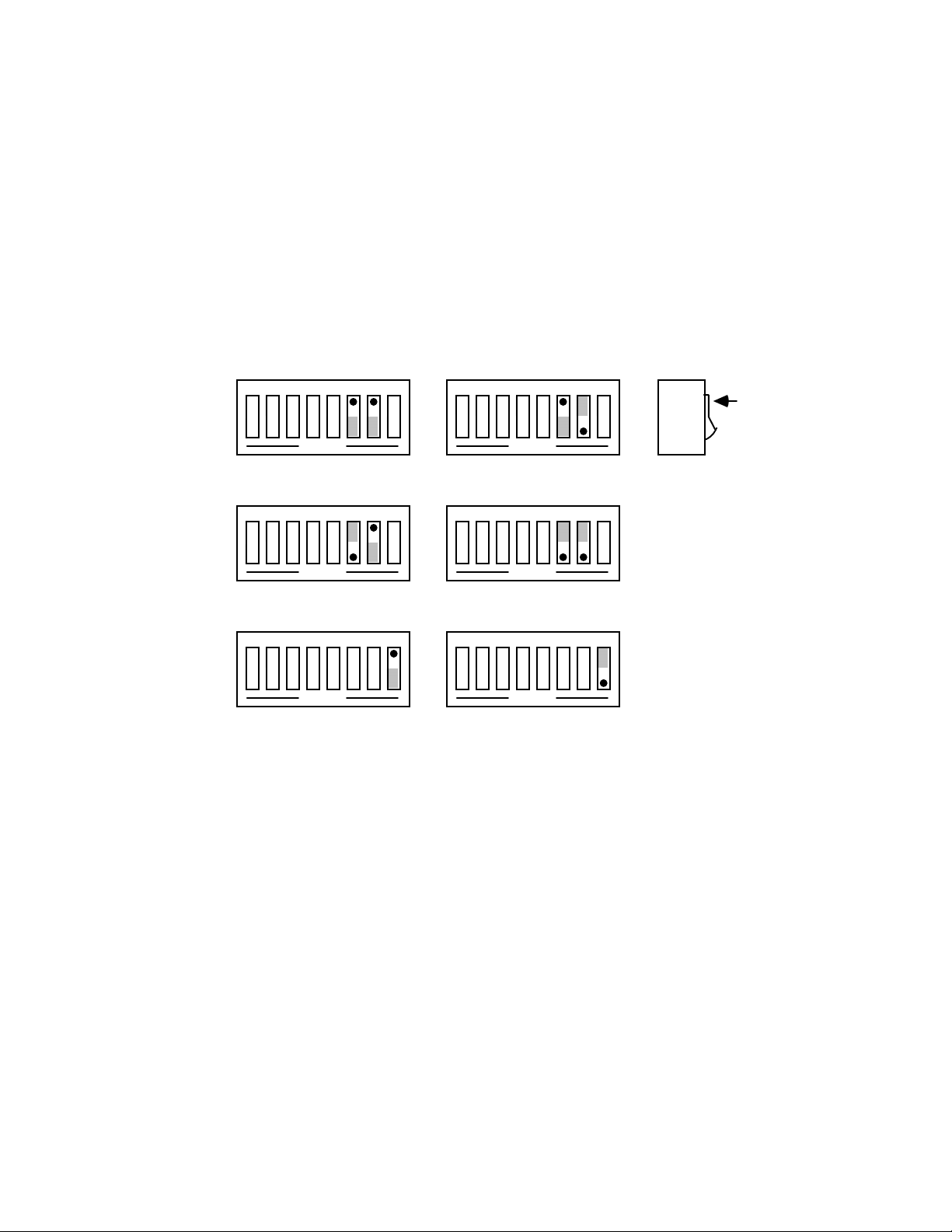
Refer to the following diagram for specific baud rates. Note: on the
Serial488/512K
selecting 57600 baud will have the same effect as selecting 19200 baud.
SW1 View for Serial Baud Rate Selection
,
12345678
110 1800
OPEN
12345678
110 2400
OPEN
12345678
110 3600
OPEN
12345678
135 4800
OPEN
12345678
150 7200
OPEN
12345678
12345678
OPEN
12345678
OPEN
12345678
OPEN
12345678
OPEN
12345678
OPEN
12345678
Switch
Side
View
DOT
300 9600
OPEN
12345678
600 19200
OPEN
12345678
1200 57600
OPEN
OPEN
12345678
OPEN
12345678
OPEN
2.7
Page 18
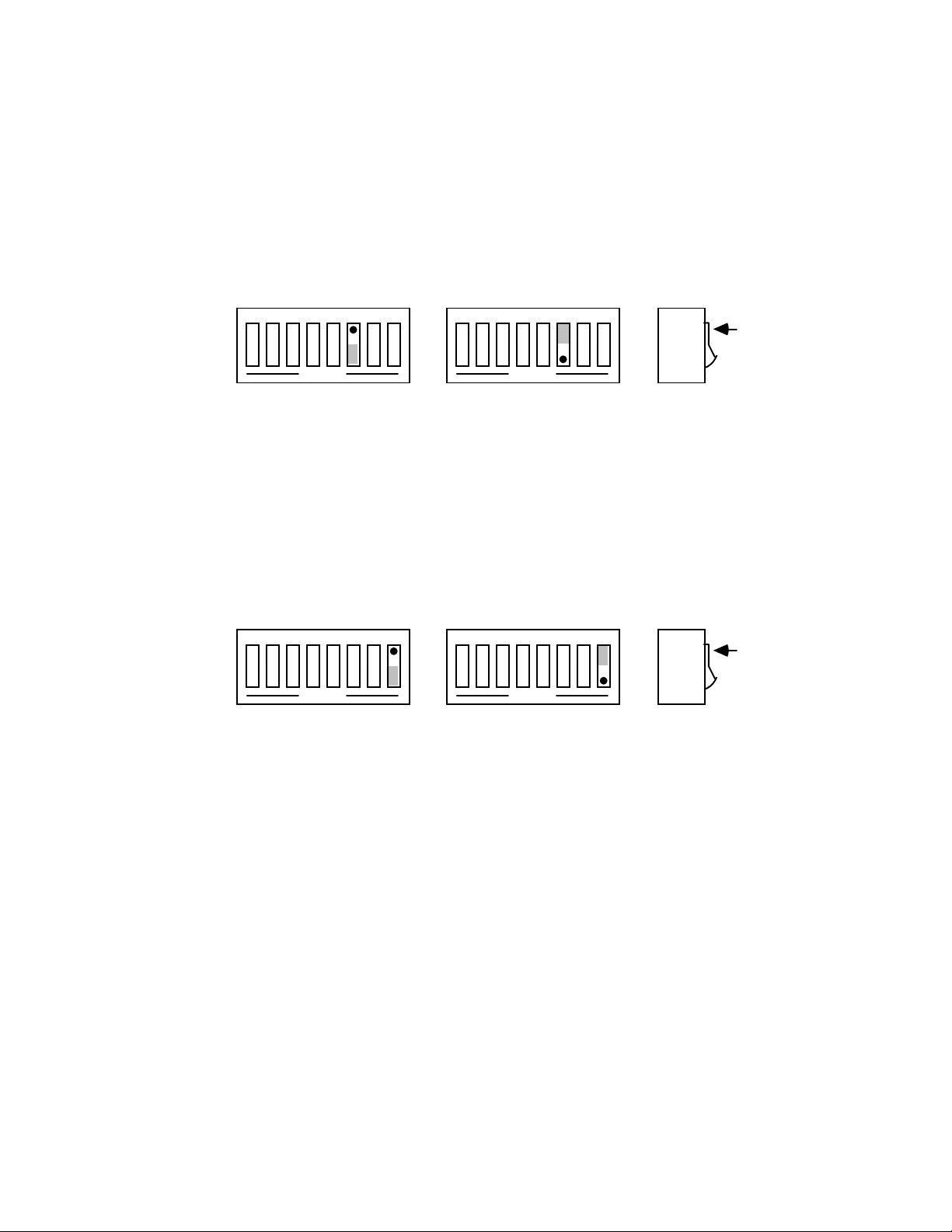
2.3.2 Serial Word Length Selection - Data Bits
SW1-6 determines the number of data bits, often referred to as word
length, for each serial character transmitted or received. The factory default
is 8 data bits.
SW1 View of Serial Word Length (Data Bits) Selection
12345678
OPEN
12345678
OPEN
Switch
Side
View
DOT
8 Data Bits 7 Data Bits
2.3.3 Serial Stop Bit Selection
Switch SW1-8 determines the number of stop bits contained in each
serial character transmitted and received. The factory default is 2 stop bits.
SW1 View for Serial Stop Bit Selection
12345678
OPEN
12345678
1 Stop Bit 2 Stop Bits
Switch
Side
View
OPEN
DOT
2.3.4 Serial Parity Selection
Serial Parity is selected with S2-6 through S2-8. The
Serial488A
generates the selected parity during serial transmissions but it does not
check parity on data that is received. The factory default is parity disabled.
2.8
Page 19
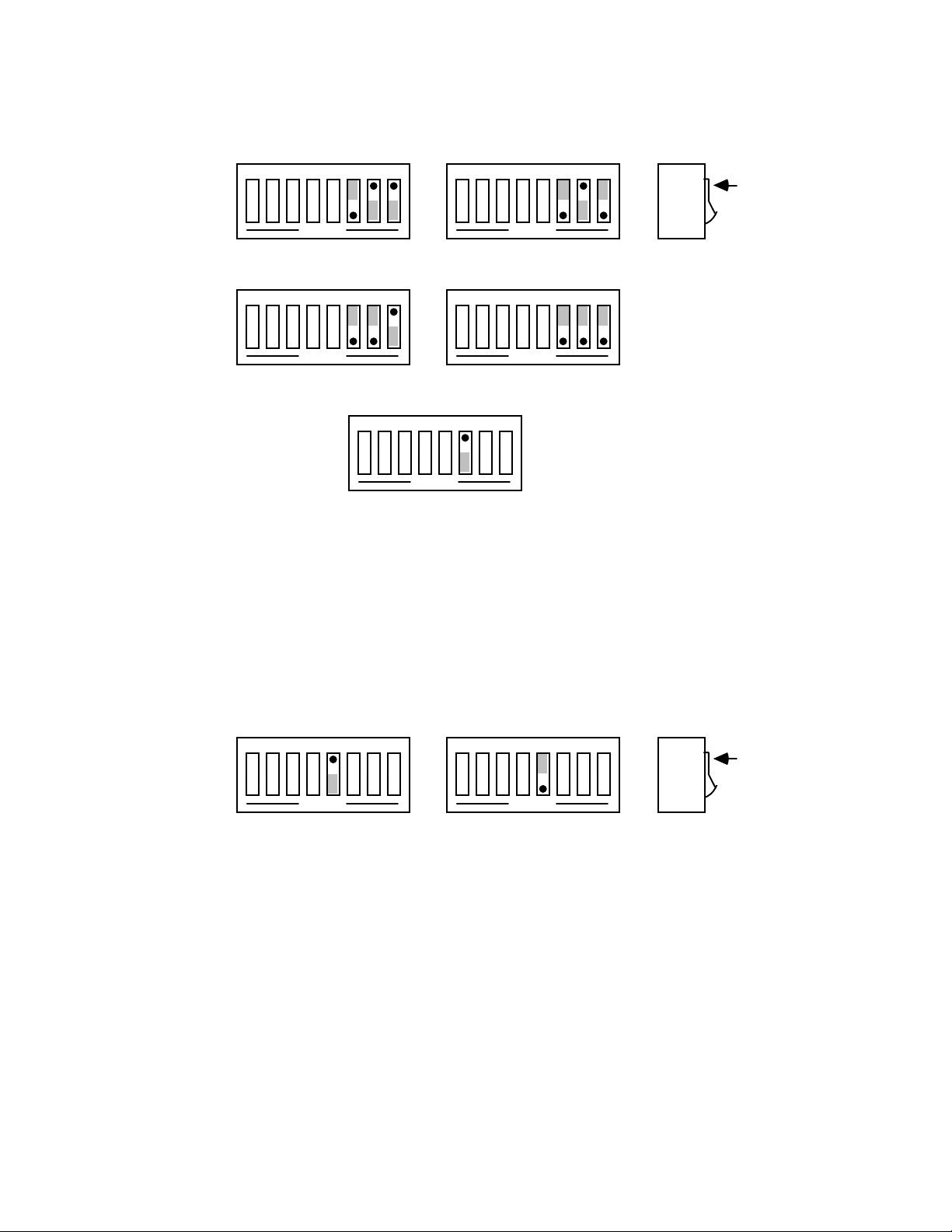
SW2 View for Serial Parity Selection
12345678
OPEN
Odd Parity Mark Parity
12345678
OPEN
Even Parity Space Parity
12345678
Parity Disabled
2.3.5 Serial Echo Selection
12345678
OPEN
12345678
OPEN
OPEN
Switch
DOT
Side
View
Serial data sent to the
Serial488A
will be echoed back to the serial
host if SW2-5 is set to the open position. Factory default is Echo Disabled.
12345678
OPEN
Echo Disabled Echo Enabled
SW2 View for Echo Selection
12345678
OPEN
Switch
DOT
Side
View
2.9
Page 20
2.3.6 Serial Handshake Selection
Switch SW1-5 is used to select between hardware [
software [
With
Xon/Xoff
Xon/Xoff
] serial handshake control.
, the
Serial488A
issues an
Xoff
RTS/CTS
character [ASCII value
] or
of $13] when its buffer memory is near full. When issued, there is greater
than 1000 character locations remaining to protect against buffer overrun.
When it is able to accept more information it issues an
[ASCII value of $11]. The
Serial488A
from the serial host it is communicating with.
becomes inactive when
Xon/Xoff
set to an active high state. The
is enabled. The
CTS
also accepts
Xon/Xoff
RTS/CTS
output is, however,
RTS
input is not used for this handshake
Xon
serial control
character
on transmit
and may be left floating (unconnected).
With
RTS/CTS
, the
Serial488A
un-asserts
(low) when its buffer
RTS
memory is near full. When un-asserted, there is greater than 1000 character
locations remaining to protect against buffer overrun. When it is able to
accept more information it asserts (high)
transmit data to the serial host if it detects the
RTS
CTS
. The
Serial488A
will not
input un-asserted (low)
when configured for this hardware handshake.
The factory default serial control is hardware,
SW1 View for Serial Handshake Selection
12345678
OPEN
RTS/CTS Xon/Xoff
12345678
OPEN
RTS/CTS
Switch
Side
View
.
DOT
2.10
Page 21
2.4 Terminator Selection
The
Serial488A
can be configured to provide RS-232 to IEEE 488 and IEEE
488 to RS-232 terminator substitution. This is useful when interfacing an RS-232
device which only issues carriage return [CR] as an output terminator to an IEEE
controller which expects a carriage return followed by a line feed [CR-LF].
In the above example, the serial terminator should be selected for CR Only while
the IEEE terminator is set to CR-LF. When a serial CR character is received, it is
discarded and substituted with an IEEE CR-LF. In the IEEE to RS-232 direction, the
IEEE CR is unconditionally discarded. Upon receipt of the IEEE LF, a serial CR is
substituted.
The
Serial488A
can be made totally data transparent by setting both the serial
and IEEE terminators to be CR Only or LF Only.
2.4.1 Serial Terminator Selection
SW2-3 and SW2-4 select the serial terminators for the serial input and
output. The factory default is LF Only.
SW2 View for Serial Terminator Selection
12345678
OPEN
CR Only LF-CR
12345678
OPEN
LF Only CR-LF
12345678
OPEN
12345678
OPEN
Switch
DOT
Side
View
2.11
Page 22
2.4.2 IEEE Bus Terminator Selection
SW3-6 through SW3-8 set the IEEE bus terminators used for data sent
or received by the
Serial488A
. EOI, a line used to signal the end of a
multiple character bus transfer, may also be enabled. If enabled, EOI is
asserted when the last selected bus terminator is sent. Factory default is LF
Only with EOI disabled.
SW3 View for IEEE Bus Terminator Selection
12345678
12345678
12345678
EOI Disabled EOI Enabled
2.5 Mode Selection
12345678
OPEN
OPEN
CR Only LF-CR
12345678
OPEN
OPEN
LF Only CR-LF
12345678
OPEN
OPEN
Switch
DOT
Side
View
SW2-1 sets the major operating mode of the
Serial488A.
The
IEEE Controller
(RS-232 to IEEE Converter) mode allows a serial host device to send data to a single
IEEE bus peripheral. Applications include interfacing a listen-only or addressable
IEEE printer/plotter to a serial printer port. Refer to
Section 3
for more detailed
information on the controller mode of operation.
2.12
Page 23
The
Peripheral
controller. Data whi ch is sent b y the IEEE control ler to t he
mode is used when interfacing a serial device to an IEEE
Serial488A
is transmitted
out its serial port. Data received from the serial device is buffered by the
until read by the IEEE controller. Refer to
Section 4
for more detailed information on
the peripheral mode of operation.
Serial488A
The factory default is the
IEEE Controller
mode, an RS-232 to IEEE converter.
SW2 View for Mode Selection
12345678
OPEN
Controller Mode Peripheral Mode
12345678
OPEN
Switch
Side
View
DOT
2.6 IEEE Address Selection
SW3-1 through SW3-5 select the IEEE bus address of the
the
IEEE Peripheral
mode. These same switches are used in the
Serial488A
IEEE Controller
mode to select the address of the device that will be controlled. [Refer to
when in
Sections 4
and 3 respectively for additional information]. The address is selected by simple
binary weighting with SW3-1 being the least significant bit and SW3-5 the most
significant. The factory default is address 10.
Listen Only
the
Serial488A
is a special type of
Peripheral
accepts all data transmitted on the bus, ignoring any bus addressing,
and transfers it out its serial port. The
Serial488A
operation. In the
is set to
Listen Only
Listen Only
mode by
mode
setting its ad dress to 31. If the IEEE address is set to 31 in the pe ripheral mode, it is
adjusted to 30.
2.13
Page 24
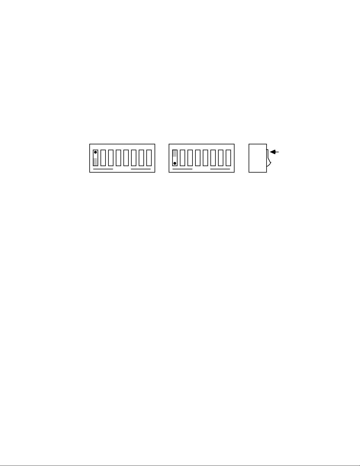
SW3 View for IEEE Address Selection
12345678
0
1
OPEN
0 x 16
1 x 8
0 x 4
1 x 2
0 x 1
+
Switch
Side
View
= 0
= 8
= 0
= 2
= 0
DOT
IEEE Address = 10
2.7 Feature Selections
The functions of the remaining switches are dependent on the mode selected. A
brief description of each of these features follows. You should refer to the listed
sections for additional information.
2.7.1 Controller Features
In the
IEEE Controller
(RS-232 to IEEE 488 Converter) mode, SW17 is used to determine whether the interface should, after sending the IEEE
bus terminators, address the attached bus device to talk. The factory default
is
Talk-back On Terminator
SW2-2 selects whether the
bus device to talk when the
device. The factory default is
Refer to
Section 3
for complete details on these features.
enabled.
Serial488A
Serial488A
should address the attached
has nothing more to send to that
Talk-back On Time Out
enabled.
2.14
Page 25
SW1 View for Controller Talk-Back on Terminator Selection
12345678
OPEN
Talk Back on
Terminator Disabled
SW2 View for Controller Talk-Back on Time-Out Selection
12345678
OPEN
Talk Back on
Time Out Disabled
2.7.2 Peripheral Features
12345678
OPEN
Talk Back on
Terminator Enabled
12345678
OPEN
Talk Back on
Time Out Enabled
Switch
DOT
Side
View
DOT
Switch
Side
View
In the
IEEE Peripheral
enables the interface to assert the
(IEEE 488 to RS-232 converter) mode, SW1-7
IEEE bus interface line to indicate
SRQ
that it has received the last switch selected serial terminator character from
the serial device.
SW1 View for Peripheral SRQ on Last Serial Terminator
12345678
OPEN
SRQ on Last
Terminator Disabled
12345678
OPEN
SRQ on Last
Terminator Enabled
Switch
Side
View
DOT
2.15
Page 26
2.8 Serial Interface
The
Serial488A
and
Serial488A/OEM
have the ability to output signal levels
that are compatible with either RS-232 or RS-422. An internal DIP shorting plug
determines which electrical specification is chosen. If the interface is to be connected
to an IBM PC/XT/AT/PS2 or compatible, the RS-232 level should be selected. If it
will be connected to a Macintosh 512K/Plus/SE/II, the RS-422 level should be used.
For connection to other computers, refer to the manufacturer's manual to determine
which levels are supported.
2.8.1 RS-232/RS-422 Signal Level Selection
The
Serial488A
's and
Serial488A/OEM
's factory default signal levels
are compatible with RS-232. To select RS-422 levels, carefully remove the
8 position shorting plug with a small flat blade screwdriver from it's socket.
Install the DIP jumper into the adjacent socket making certain that all of
the pins on the shorting plug are inserted correctly. The following diagrams
show which socket the jumper must be inserted for the desired operation.
RS-232 Signal Levels Selected - Serial488A
Shorting Plug
J205
RS-422 RS-232
J206
2.16
Page 27

RS-232 Signal Levels Selected - Serial488A/OEM
J106
RS-232
J105
RS-422
Shorting Plug
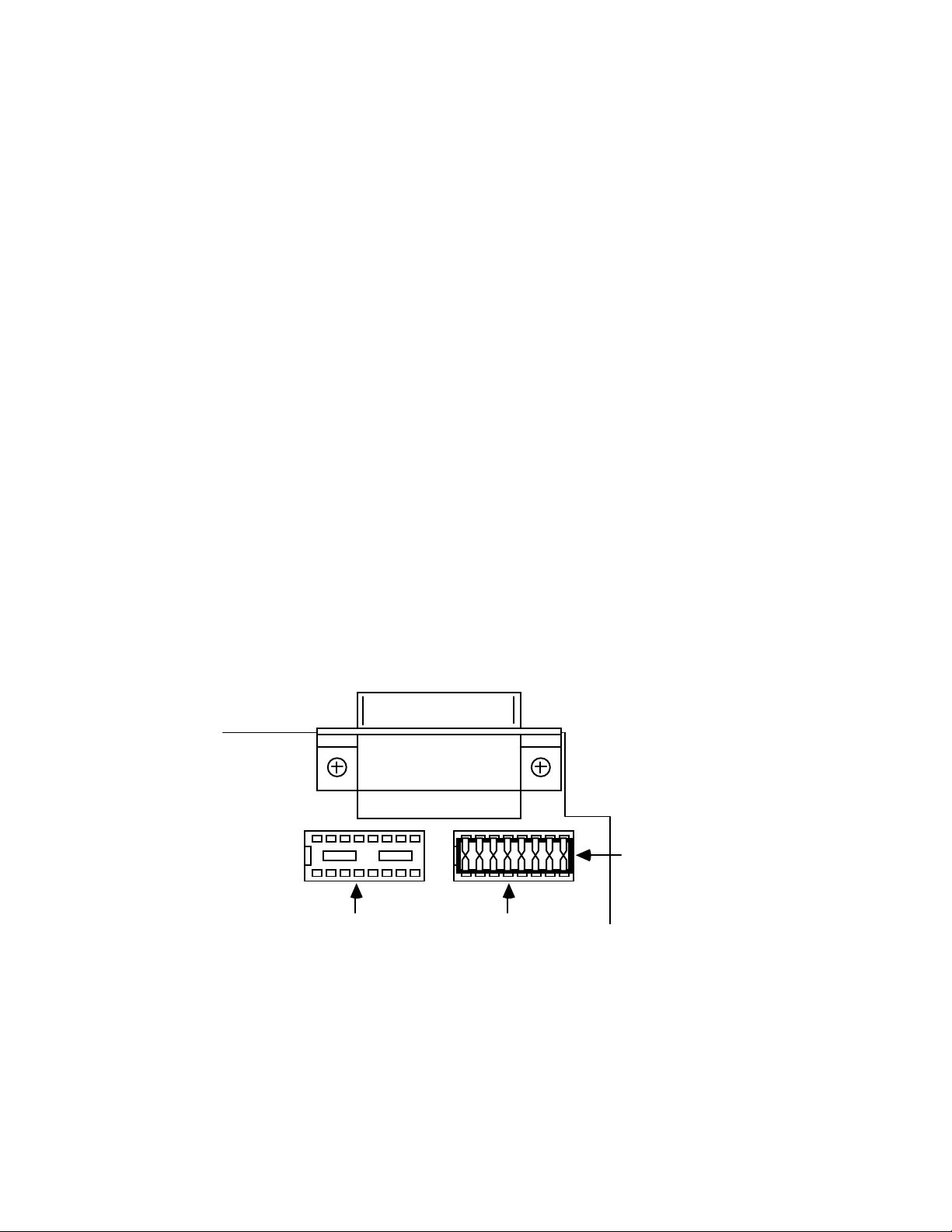
2.8.2 Serial Signal Descriptions
The
Serial488A
is equipped with a standard DB-25S connector on its
rear panel and requires a standard DB-25P mating connector. The
Serial488A
communications, which means the
's connector is configured as DCE type equipment for RS-232
Serial488A
always transmits data on
Pin 3 and receives data on Pin 2. The following list describes the RS-232
and RS-422 signals provided on the
Serial488/512K
does not support RS-422 communication, the pins labeled
Serial488A
. Note: since the
+TxD and +RxD are not used. Any reference to RS-422 communication
does not apply to the
Serial488/512K
.
2.17
Page 28

Rear View of the Serial488A's Serial Connector
+VTEST
GND
13
25
-RxD Receive Data - Input - Pin 2
This pin accepts serial data sent by the RS-232 or RS-422 host.
The serial data is expected with the word length, baud rate, stop
bits and parity selected by the internal switches. The signal level is
low true.
-TxD Transmit Data - Output - Pin 3
This pin transmits serial data to the RS-232 or RS-422 host. The
serial data is sent with the word length, baud rate, stop bits and
parity selected by the internal switches. The signal level is low
true.
CTS
RTS
+VTEST
+TXD
-RXD
-TXD
+RXD
1
14
CTS Clear To Send - Input - Pin 4
The
Serial488A
input is used as a hardware handshake line to prevent the
CTS
from transmitting serial data when the RS-232 host is
not ready to accept it. When
the internal switches, the
while this line is un-asserted (low). If the RS-232 host is not
TxD
Serial488A
capable of driving this line it can be connected to the
(Pin 6) of the
line is not tested to determine if it can transmit data.
CTS
Serial488A
. If
2.18
RTS/CTS
will not transmit data out
Xon/Xoff
handshake is selected on
Vtest
output
handshake is selected, the
-
Page 29

RTS Request To Send - Output - Pin 5
The
output is used as a hardware handshake line to prevent
RTS
the RS-232/RS-422 host from transmitting serial data if the
Serial488A
is not ready to accept it. When
is selected on the internal switches, the
output high when there are greater than 1000 character
RTS
locations available in its internal buffer. If the number of available
locations drops to less than 1000, the
(low) this output. If
Xon/Xoff
handshake is selected, the
will be permanently driven active high.
Vtest Test Voltage - Output - Pin 6
This pin is connected to +5 volts through a 1K• resistor. It is also
common to Vtest on pin 9.
Gnd Ground - Pin 7
This pin sets the ground reference point for the other RS-232
inputs and outputs.
RTS/CTS
Serial488A
Serial488A
handshake
will drive the
will un-assert
line
RTS
Vtest Test Voltage - Output - Pin 9
This pin is connected to 5 volts through a 1K• resistor. It is also
common to Vtest on pin 6.
+RxD Receive Data Plus - Input - Pin 14
This pin accepts serial data sent by the RS-422 host. The serial
data is expected with the word length, baud rate, stop bits and
parity selected by the internal switches. The signal level is high
true and only connected to this pin when RS-422 operation is
selected. It is 180° out of phase with
-RxD
+TxD Transmit Data Plus - Output - Pin 16
This pin transmits serial data to the RS-422 host. The serial data
is sent with the word length, baud rate, stop bits and parity
selected by the internal switches. The signal level is high true and
only connected to this pin when RS-422 operation is selected. It is
180° out of phase with
-TxD
.
.
2.19
Page 30

2.8.3 Serial Cable Wiring Diagrams
If a cable was not purchased with the interface, the following diagrams
will be helpful in making your own cable. Simple soldering skills and an
attention to detail will ensure successful construction.
Macintosh to Serial488A Wiring Diagram (RS-422)
Macintosh to Serial488A
DB-9 Male DB-25 Male
RTS
CTS
-TxD
Gnd
-RxD
+TxD
+RxD
6
7
5
3
9
4 14 +Rxd
8 16 +Txd
4
CTS
5
RTS
2
-RxD
7
Gnd
3
-Txd
Macintosh Plus/SE/II to Serial488A Wiring Diagram (RS-422)
Macintosh II/SE/Plus to Serial488A
Mini DIN8 Male DB-25 Male
RTS
CTS
-TxD
1
2
3
4
CTS
5
RTS
2
-RxD
Gnd
-RxD
+TxD
+RxD
4
5
6 14 +Rxd
8 16 +Txd
2.20
7
Gnd
3
-Txd
Page 31

IBM PC/XT/PS2 to Serial488A Wiring Diagram (RS-232)
IBM PC/XT/PS2 to Serial488A
DB-25 Female DB-25 Male
-TxD
-RxD
RTS
CTS
DSR
Gnd
2
3
4
5
6
2
3
4
5
6
-RxD
-TxD
CTS
RTS
Vtest
7 7 Gnd
IBM AT to Serial488A Wiring Diagram (RS-232)
IBM AT to Serial488A
DB-9 Female DB-25 Male
DCD
-RxD
-TxD
DTR
1
2
3
3
-TxD
2
-RxD
4
Gnd
DSR
RTS
CTS
5
7
Gnd
6
7
8
4 CTS
5 RTS
Note: Standard AT 9 Pin to 25 Pin adapter cables are not wired as shown above and will
not work with the Serial488A.
2.21
Page 32

2.9 General Operation
Refer to the following sections for specific operational modes. This sub-section
gives a general test of functionality. After setting the power on defaults and
reassembling the
Serial488A
, plug the power supply connector into the rear jack on
the interface.
CAUTION
Never install the power supply into the interface
while it is connected to AC line power. Failure
to observe this caution may result in damage to
the Serial488A.
WARNING
The power supply provided with the interface is
intended for INDOOR USE ONLY. Failure to
observe this warning could result in equipment
failure, personal injury or death.
After installing the power supply connector into the interface, plug the power
supply into AC line power. Place the rear panel power switch in the ON [1] position.
All the front panel indicators should light momentarily while the
Serial488A
performs
an internal ROM and RAM self check. At the end of this self check all indicators
except
POWER
should turn off.
If there is an error in the ROM checksum, all of the LEDs will remain on.
Flashing LEDs indicates a RAM failure. Should such an error occur, turn the rear
panel switch to the OFF [0] position and retry the above procedure.
When the
Serial488/512K
is first powered on, it performs a self test which lasts
approximately 15 seconds. The front panel LED's will flash while the self test is
performed. If the unit is functional, all LED's except power should turn off after the
self test is completed. If one or more LED's remains flashing, refer to the Hardware
Fault Identification Table to determine the cause of error.
2.22
Page 33

Hardware Fault Identification Table - Serial488/512K
Error Talk Listen Empty Full Power
No Error off off on off on
No Error--Listen Only off on on off on
No Power off off off off off
Program Rom on on on on on
Ram - U209 blink off off off on
Ram - U210 blink off on off on
Ram - U211 blink off off on on
Ram - U212 blink off on on on
Ram - U213 blink on off off on
Ram - U214 blink on on off on
Ram - U215 blink on off on on
Ram - U216 blink on on on on
Ram - U208 off off off blink on
Ram - U201 off off on blink on
Ram - U202 off on off blink on
Ram - U203 off on on blink on
Ram - U204 on off off blink on
Ram - U205 on off on blink on
Ram - U206 on on off blink on
Ram - U207 on on on blink on
Logic Error blink blink blink blink on
2.23
Page 34

If the front panel indicators do not flash and the
POWER
indicator does not
remain lit there may not be any power supplied to the interface. In this event, check
the AC line and the rear panel connection of the power supply for proper installation.
If the problem is unresolved, refer to the
Service Information
section of this manual.
If proper operation is obtained, connect an interface cable to the rear of the
Serial488A
for connecting IEEE bus instruments, the
[ 25-Pin Sub-D ]. Connect the other end to the host's serial port. Except
Serial488A
is installed and ready to use.
WARNING
The Serial488A makes its earth ground
connection through the serial interface cable. It
should only be connected to IEEE bus devices
after being first connected to the host. Failure to
do so may allow the Serial488A to float to a bus
device test voltage. This could result in damage
to the interface, personal injury or death.
2.24
Page 35

Controller Operation
3.1 Controller Mode (Serial to IEEE) Operation
The
IEEE Controller
send data to a single IEEE bus peripheral or to multiple peripherals if they occupy the
same bus address. Applications include interfacing a listen-only or addressable IEEE
printer/plotter to a serial printer port.
Once the
input data. When received, it addresses the selected IEEE device to listen with the
following bus sequence:
The data received from the serial host is placed into a circular serial input buffer.
Simultaneously, characters are removed from that buffer and sent to the IEEE bus
device. The serial terminator(s), if present, are not sent. Instead, the IEEE terminators
are substituted and sent in their place.
So long as the serial input buffer is not empty, the
send data from it to the IEEE bus device. If the serial input buffer becomes emptied,
the
Serial488A
features is enabled. This allows the
devices, such as plotters or instruments, that return status and other information to the
host computer.
Serial488A
will command the IEEE bus device to talk if one of the talk back
mode allows a serial RS-232 or RS-422 host device to
has initialized itself after power-on, it waits for serial
ATN•UNL,MTA,LAG,*ATN
will continue to
Serial488A
Serial488A
to be used as a controller with
When the
bus sequence:
The
Serial488A
until the last selected IEEE terminator is detected. The IEEE bus terminators are
replaced by the serial terminators and these are then sent to the serial host.
Serial488A
then accepts data from the IEEE device an d ret u rn s i t to t h e ho s t
addresses the IEEE bus d ev ice t o t alk i t us es t he fo l l owi ng
ATN•UNL,MLA,TAG,*ATN
3.1
Page 36

If the IEEE device has been addressed to talk but does not respond or finish
transmission by the time additional characters are received into the circular serial
input buffer, the talk sequence will be aborted to allow additional serial information to
be sent to the IEEE device.
3.2 Serial and IEEE Terminator Substitution
The
Serial488A
can be configured to provide serial to IEEE 488 and IEEE 488 to
serial terminator substitution. This is useful when interfacing a serial host which only
issues carriage return [CR] as an output terminator to an IEEE peripheral which
expects a carriage return followed by a line feed [CR-LF].
In this previous example, the serial terminator should be selected for CR Only
while the IEEE terminato r is set for CR-LF. When a s erial CR character is received it
is discarded and substituted with an IEEE CR followed by an IEEE LF. In the IEEE to
serial direction, the IEEE CR is unconditionally discarded. Upon receipt of the IEEE
LF a serial CR is substituted.
The
Serial488A
can be made totally data transparent by setting both the serial
and IEEE terminators t o be CR Only or LF Only. Refer to Section 2 fo r the proper
switch settings for both the IEEE and serial terminators.
3.3 IEEE Address Selection
SW3-1 through SW3-5 select the IEEE bus address of the IEEE peripheral the
Serial488A
device that will be controlled, not the address of the
Serial488A
will be communicating with. These switches set the address of the IEEE
Serial488A
. The address of the
is automatically adjusted so that address conflicts will not occur. The
address is selected by simple binary weighting with SW3-1 being the least significant
bit and SW3-5 the most significant. If address 31 (reserved on the IEEE bus) is
selected in the controller mode, address 30 is assigned as the device it will be
communicating with. The following figure shows the IEEE address selection of 10.
3.2
Page 37

SW3 View for IEEE Address Selection
12345678
0
1
OPEN
0 x 16
1 x 8
0 x 4
1 x 2
0 x 1
+
Switch
Side
View
= 0
= 8
= 0
= 2
= 0
DOT
IEEE Address = 10
3.4 Talk Back Features
Two different switch selectable talk back features are included to provide bidirectional communication with the IEEE device. Whether either talk back feature
should be enabled is dependent on the application.
3.4.1 Talk Back On Terminator
SW1-7 is used to determine whether the interface should address the
attached bus device to talk after sending the selected IEEE bus
terminator(s). This feature is commonly used to provide bi-directional
communication wit h a si ngl e IEEE ins trumen t. Talk back will on ly occu r i f
there is no serial dat a to output to the IEEE device. The fact ory default is
Talk-back On Terminator
enabled.
SW1 View for Talk-Back on Terminator Selection
12345678
OPEN
Talk Back on
Terminator Disabled
12345678
OPEN
Talk Back on
Terminator Enabled
Switch
Side
View
DOT
3.3
Page 38

When the serial input buffer becomes empty, the
Serial488A
checks
the last characters sen t to the IEEE b us device. If th ese were the IEEE bus
terminators and
Talk-Back on Terminator
device is addressed to talk. Any data received by the
is enabled, the IEEE bus
Serial488A
from the
bus device is sent to the serial host.
When the last IEEE bus t erminator is detected from the IEEE d evice,
the
Serial488A
disables the device from sending additional information by
asserting Attention (ATN) on the bus.
If the IEEE device does not responded or finish transmission by the
time additional characters are received into the serial input buffer, the talk
sequence will be aborted to allow additional serial information to be sent to
the IEEE device.
The following is an example of how this feature can be used to
communicate with a single IEEE instrument. The program example is
written in Basic on an IBM PC or compatible and communicates with a
Keithley Model 196 DMM.
10 '
20 ' Example Program using Serial488A with
25 ' the Talk Back on Terminator Feature Enabled to
30 ' Communicate with a Keithley Model 196 DMM
40 '
50 ' Open Basic's serial communications port
60 OPEN "COM1: 9600,N,8,2" AS 1
70 ' Set the Model 196 DMM to the 30VDC range
80 PRINT #1,"F0R3X"; ' The ; suppresses terminators
90 ' Request 10 Readings from 196"
100 FOR N = 1 to 10
110 PRINT #1,"" ' Output terminator
120 LINE INPUT #1, A$ ' Get Reading from 196
130 PRINT A$ ' print it on the screen
140 NEXT N
150 END
3.4
Page 39

3.4.2 Talk Back On Time Out
SW2-2 selects whether the
bus device to talk when the
Serial488A
Serial488A
should address the attached
has no more serial data to send.
This feature relies on time and not on terminators. Its use is primarily for
simulating a serial plotter from an IEEE 488 [HP-IB] plotter. The factory
default is
Talk-back On Time Out
enabled.
SW2 View for Talk-Back on Time-Out Selection
12345678
OPEN
Talk Back on
Time Out Disabled
If
Talk-Back on Time-Out
12345678
OPEN
Talk Back on
Time Out Enabled
is enabled, then
Switch
Side
View
Serial488A
DOT
waits
approximately 100 milliseconds after it detects its serial input buffer is
empty. If no serial character has been received by the end of this time, the
IEEE bus device is addressed to talk. The choice of talk-back modes
depends strongly on the type of device and software being used. For most
plotter applications the
Talk-back on Time-Out
feature should be
enabled.
When the last IEEE bus t erminator is detected from the IEEE d evice,
the
Serial488A
disables the device from sending additional information by
asserting Attention (ATN) on the bus. If the IEEE device does not respond
or finish transmission by the time additional characters are received into
the serial input buffer, the talk sequence will be aborted to allow additional
serial information to be sent to the IEEE device.
Most IEEE 488 plotters will not respond to the talk address sequence
with output data unless there has been a specific device dependent
command sent to tell them what to say. If they have not been told what to
say, they say nothing.
3.5
Page 40

The following is an example of how this feature can be used to
communicate with an IEEE plotter. The program example is written in
Basic on an IBM PC or compatible. It turns the PC into a dumb serial
terminal. When a key is pressed on the keyboard, the character is
transmitted out of the serial (COM1) port. Any serial data which is
received from the port is printed on the display.
10 ' Dumb Terminal Program for the Serial488A
20 ' This Program allows direct interaction
between
30 ' the IBM-PC and an IEEE plotter through the
40 ' Serial488A. The Serial488A must have talk
back
50 ' on time out enabled.
60 'Open the serial communications port
70 OPEN "COM1: 9600,n,8,2,cs,ds" AS 1
80 ' Display any data received from the COM1 port
90 IF LOC(1) THEN PRINT INPUT$(LOC(1),1);: GOTO 90
100 ' Transmit key presses to the COM1 port and
screen
110 K$=INKEY$
120 PRINT #1,K$; : PRINT K$;
130 GOTO 90 ' Do it again
Enter the program into the computer and run it. The example below shows
how to test the
Serial488A
's operation with a Hewlett Packard 7470A
plotter. Other IEEE plotters are similar but you should refer to the plotter's
programming manual for the proper command syntax. Notice the
Serial488
's front panel LEDs as you type the plotter commands.
Type the following HPGL output identify command on the keyboard.....
OI;
The plotter (HP 7470A) should immediately respond with.....
7470A
By typing the following HPGL command on the keyboard, the plotter
should respond by retrieving its pen, drawing a line and returning the pen.
SP1;PA1000,1000;PD;PA1000,6000;PU;SP0;
3.6
Page 41

3.5 Plotter Applications
To use the
Serial488A
to interface an HP-IB plotter to a serial computer port,
you will need the following information about your system.
1. The serial data format that the application (plotting or graphics)
program expects the plotter to communicate with. These parameters
include baud rate, word length, stop bits, parity and serial control.
Some programs allow these parameters to be selected by the user.
Other graphics programs depend on the RS-232 version of the plotter
defaults. Usually, Hewlett Packard plotters use 9600 baud, 7 data bits,
1 stop bit, even parity and Xon/Xoff serial control. Since these
plotters are available with serial interfaces, the operator's manual of
your IEEE plotter should contain this information.
2. The IEEE bus address of your plotter. This address is usually set by a
DIP switch located on the rear of the plotter. The first five switches set
the address which, for Hewlett Packard plotters, is usually address 5.
Refer to the plotter's operator's manual for exact information.
Set the
Serial488A
's internal DIP switches to match the parameters determined
above. Other parameters which should be selected include…
1. Talk Back on Terminator Enabled.
2. Talk Back on Time Out Enabled.
3. Serial Terminators set to CR Only.
4. IEEE Terminators set to CR Only with EOI enabled.
3.7
Page 42

An IBM PC based Graphics System
The following shows the
Serial488A
's internal switch settings required to use a
Hewlett Packard 7580A plotter with AutoCad™ from AutoDesk on an IBM PC or
compatible. Because PC and compatibles output RS-232 levels, the shorting DIP
jumper should be set to the RS-232 position (J206).
Selecting RS-232 Signal Levels - Serial488A
Shorting Plug
J205
RS-422 RS-232
J206
3.8
Page 43

Selecting RS-232 Signal Levels - Serial488A/OEM
J106
RS-232
RS-422
Shorting Plug
J105
3.9
Page 44

Serial488A Settings For Use With HP 7580A Plotter on an IBM PC
SW3
EOI
5
CR Only
Enabled
IEEE Addr
IEEE Term
Mode
Talk Back on Time Out
Serial Term
Echo
Parity
12345678
OPEN
12345678
SW2
OPEN
C
Enabled
CR
No Echo
Even
Switch
DOT
Side
View
DOT
Switch
Side
View
Baud Rate
Handshake
Word Length
Talk Back on Terminator
Stop Bits
12345678
SW1
OPEN
9600
Xon/Xoff
7 Data Bits
Enabled
1 Stop Bit
Switch
DOT
Side
View
3.10
Page 45

When using the
Serial488A
with plotting programs on the Macintosh™
computer with graphic drivers such as MacPlot™, some serial data format parameters
are user modifiable. The following is a partial MacPlot configuration screen which
allows selection of baud rate, stop bits and parity. With this driver, the word length is
fixed to 7 data bits with Xon/Xoff serial control. These non-modifiable defaults are
plotter dependent. Refer to the plotter or driver manual for the defaults of the specific
plotter.
For this example, 57600 baud with one stop bit and no parity has been chosen
for the serial data format.
MacPlot™ Configuration Screen
3.11
Page 46

A Macintosh based Graphics System
The Macintosh computer outputs RS-422 levels. Because of this, the internal
DIP shorting jumper is set to the RS-422 position (J205).
Selecting RS-422 Signal Levels - Serial488A
Shorting Plug
J205
RS-422 RS-232
J206
3.12
Page 47

Selecting RS-422 Signal Levels - Serial488A/OEM
J106
RS-232
J105
RS-422
Shorting Plug
3.13
Page 48

The following illustrates the
Serial488A
's internal switch settings for use with
MacPlot utilizing the previously described format.
Serial488A Settings For Use With HP 7580A Plotter on a Macintosh
SW3
EOI
5
CR
Enabled
IEEE Addr
IEEE Term
Mode
Talk Back on Time Out
Serial Term
Echo
Parity
12345678
OPEN
12345678
SW2
OPEN
C
Enabled
CR
No Echo
No Parity
Switch
DOT
Side
View
DOT
Switch
Side
View
Baud Rate
Handshake
Word Length
Talk Back on Terminator
Stop Bits
12345678
SW1
OPEN
57600
Xon/Xoff
7 Data Bits
Enabled
1 Stop Bit
3.14
Switch
DOT
Side
View
Page 49

After configuration, turn on the plotter and the
Serial488A
. The
Serial488A
's
front panel LEDs should all light momentarily while it performs an internal ROM and
RAM test. All LEDs should go out except for the Powe r and Talk LED. The Talk LED
indicates that the
Serial488
has detected the plotter on the IEEE bus and has
addressed it to listen.
When the serial host begins to send the
Serial488
data, the Receive LED will
flash. If it does not, this indicates that the interface is not receiving data from the serial
host. Verify the cables are connected properly and the serial cable wiring. Verify the
serial data format, word length, stop bits and parity.
3.6 Printer Applications
Most of the information given for plotter applications applies to applications for
interfacing IEEE 488 printers to a serial host. Some high end printers have a
secondary command setting which must be disabled for the
them. The
Serial488
does not use secondary commands to control IEEE peripherals,
Serial488A
to control
such as printers or plotters. Refer to the printer's instruction manual if the is a question
as to whether the printer requires secondary commands.
3.15
Page 50

Peripheral Operation
4.1 Peripheral Mode Operation
This mode of operation is useful in interfacing a serial device, such as a serial
printer, plotter or i nstrument, to an IEEE contro ller. Data which is sent b y the IEEE
controller to the
received from the serial device is buffered by the
controller. The
32,000 bytes of data from both the IEEE input and the serial input. The
Serial488/512K
serial input.
Serial488A
Serial488A
can buffer 512,000 bytes of data from both the IEEE input and the
is buffered and transmitted out its serial port. Data
until read by the IEEE
can buffer approximately
and the
Serial488A
Serial488A/OEM
The
Serial488A
its buffer memory is full. It does this by preventing completion of the bus
handshaking sequences. It will also request that additional serial data not be sent by
negating its Request To Send (
character. The serial handshake used is dependent on the handshake selection (Refer
to
Section 2
4.2 Serial and IEEE Input Buffers
Memory in the
IEEE input buffers. This allows for the most efficient partitioning of memory for any
given application.
At power on, or device clear, each buffer is allocated a 128 byte mini-buffer or
queue. When the serial input [or IEEE input] requires more buffer space, additional
queues are allocated. When a queue is empty, it is released from the input buffers so
that it may be re-allocated when, and where, required.
).
will refuse to accept more data from the IEEE controller when
Serial488A
) output or by transmitting the
RTS
is dynamically allocated for the serial input and
Xoff
ASCII
There are approximately 250 available queues in the
Serial488A/OEM
continually allocated and released as required by the serial and IEEE input. Of the 250
available queues, 240 are issued without regard to controlling the receipt of additional
serial or IEEE input data.
for a total of 32,000 bytes of buffer (character) space. Queues are
4.1
Serial488A
and the
Page 51

When the serial input buffer requests one of the last 10 queues (1280 character
locations left), it signals the serial host that it should stop sending data. This is
accomplished by either un-asserting RTS or issuing "Xoff", depending on which serial
handshake control has been switch selected. When more than 10 queues become
available, it asserts RTS or issues "Xon".
The IEEE bus input signals that the IEEE input (or serial output) buffer is full
when the number of queues available drops below 10 (1280 character locations left).
When the number of available queues drops to 4 or less (512 character locations left),
the IEEE interface of the
Serial488A
stops accepting data from the bus. This bus
hold-off will only occur until additional queues (greater than 4) become available. At
that time it will resume accepting bus data.
4.3 IEEE Data Transfers
The following methods may be used by the IEEE controller when sending data
to the
Serial488A
:
4.3.1 Blind Bus Data Transfers
If the IEEE controller does not mind waiting an indefinite time for
data space in the buffer to become available, the data can simply be sent to
the
Serial488A
controller is blind as to whether or not the
. This is referred to as blind data transfers because the IEEE
Serial488A
is capable of
accepting data. In this case, the bus controller's output data transfer will be
held off by the
Serial488A
if it is unable to buffer the data. It will resume
accepting IEEE input data when memory becomes available. This type of
control might be appropriate in a single user environment.
To illustrate how this would appear, let's assume the
Serial488A
is
connected to a serial device which will accept data at 1200 baud or 110
bytes per second. The IEEE bus controller is capable of sending data to the
Serial488A
at a rate of 5000 bytes per second. The data would be
transferred on the bus at 5000 characters per second for slightly over six
seconds, filling over 31,000 locations. At that time, the IEEE input would
hold off additional data transfers until 128 characters are sent out the serial
port at rate of 110 characters per second. This 110 cps would then become
the average bus data acceptance rate of the
Serial488A
.
If the controller is set to detect a data time-out error, then it will do so
if the
Serial488A
holds off IEEE input data transfers for too long. The
4.2
Page 52

error can be used to alert the operator to the problem, such as a printer out
of paper, so that it can be corrected. If the controller then restarts
transmission exactly where it left off, no data will be lost.
If data is requested by the controller and no serial input data is
available in the
Serial488A
, the bus will hang until serial data is received.
If no serial data is received it will hang forever or until the controller times
out.
4.3.2 Controlled Bus Data Transfers
If the controller must avoid waiting for the serial device, it can 'serial
poll' the
Serial488A
. Serial poll is a method by which the controller can
inquire the internal status of the interface without disturbing any data being
transferred, slowing data transfers or locking up the bus. You should refer
to the programming manual of your controller to determine the method of
performing serial polls.
When serial polled, the
Serial488A
provides eight bits of status
information to the controller. The most significant bit [DIO8] of the
Serial488A
's serial poll byte is set to a logic "1" when the IEEE input
buffer is NOT EMPTY. The term NOT EMPTY is used to signify that not
all of the previous data sent to the interface has been transmitted to the
serial device. If it is NOT EMPTY, the controller may avoid sending any
more data to the
Serial488A
. If this bit is a logic "0", then the serial device
has accepted all previous data and the IEEE controller may send more.
Another bit [DIO4] of the Serial Poll byte is used to indicate
additional information concerning the IEEE input buffer. This bit is set to
a logic "1" when there is 1280 or less locations in the buffer for data. It is
cleared, set to a logic "0", when there is greater than 1280 locations
available. This bit is referred to as the IEEE input buffer FULL bit.
4.3
Page 53

When serial data is received, DIO5 of the Serial Poll byte is set, '1', to
indicate to the IEEE controller that the serial input buffer is NOT EMPTY.
If set, it indicates that at least one character is available in the serial input
buffer to be read by the IEEE controller. Once all of the serial input data is
read by the IEEE controller this bit is reset.
The
Serial488A
receives the last serial terminator. To enable this feature, the
switch, located on the internal switch bank of SW1, must be enabled.
SRQ
When enabled, the
can generate a request for service on the bus when it
Peripheral
Serial488A
will assert the IEEE b us
line and set
SRQ
serial poll status bits DIO7 and DIO3 when the last serial terminator is
detected. The IEEE controller must perform a serial poll on t he interface to
clear the
SRQ
. If the
Peripheral SRQ
switch is in the disabled position,
there will still be an indication in the serial poll status byte that the last
serial input terminator was received, but
service request (
SRQ
).
Serial488A
will not generate a
SW1 View For Selecting SRQ on Last Terminator
12345678
OPEN
SRQ on Last
Terminator Disabled
12345678
OPEN
SRQ on Last
Terminator Enabled
Switch
Side
View
DOT
4.4 Serial Poll Status Byte Register
The following shows and describes the serial poll status information provided by
the
Serial488A
.
DIO8 IEEE Input Buffer NOT Empty
This bit is set when the IEEE input buffer contains one or more
data bytes which have not been sent out the serial port. It is
cleared, set to "0", when the buffer is empty.
4.4
Page 54

Serial Poll Status Byte
1428163264128
DIO8 DIO7 DIO6 DIO5 DIO4 DIO3 DIO2 DIO1
ce - rsv bit
ffer Not Empt y
Serial Handsh ake
Not Used - Al ways '0'
Request Servi
IEEE Input Bu
Serial Input Buffer Not Em pty
IEEE Input Bu ffer Full
DIO7 rsv
This bit is defined by the IEEE 488 Specification and is used to
indicate to the bus controller that the
that requested service. It is cleared when the interface is serial
polled by the controller.
DIO6 Not Defined - Always "0"
DIO5 Serial Input Buffer NOT EMPTY
This bit is set when the serial input buffer contains one or more
data bytes which have not been sent out the IEEE bus. It is
cleared, set to "0", when the buffer is empty.
Last Serial I nput Terminat or
Serial488A
Not Used - Al ways '0'
is the bus device
4.5
Page 55

DIO4 IEEE Input Buffer Full
When this bit is set, it indicates that the
the controller on subsequent data transfers. The interface may
continue to accept an additional 512 characters but this is
dependent on the serial input buffer size.
DIO3 Received Last Serial Terminator
This bit is set [1] when the
Serial488A
terminator at its serial input. It remains set as long as there is at
least one serial terminator in the serial input buffer. If the
Peripheral SRQ
feature is enabled, the
request for service by asserting the
bit [DIO7]. The
bit is cleared, along with the
rsv
serial polled by the controller. If there are additional serial
terminators in the serial input buffer,
SRQ
line and
bit when the last IEEE 488 bus terminator is sent
rsv
to the IEEE 488 controller.
DIO2 Serial Handshake
This bit indicates the present state of the serial handshake. If it is
set to "1", the serial device connected to the
of accepting serial data. If "0", the RTS line is unasserted, if
configured for hardware handshake, or the "Xoff" character has
been received, if configured for Xon/Xoff software handshake.
Serial488A
detects the last serial
Serial488A
line and also set the
SRQ
SRQ
Serial488A
will reassert the
Serial488A
may hold off
will issue a
rsv
line, when
is capable
DIO1 Not Used - Always "0"
4.5 Use of Serial and Bus Terminators
The
Serial488A
can be configured to provide RS-232 to IEEE 488 and IEEE
488 to RS-232 terminator substitution. This is useful when interfacing a serial device,
which only issues carriage retu rn [CR] as an output terminator, to an IEEE controller,
which expects a carriage return followed by a line feed [CR-LF].
4.6
Page 56

In the previous example, the serial terminator should be selected for CR Only
with the IEEE terminator set to CR-LF. When a serial CR character is received it is
discarded and substituted with an IEEE CR followed by an IEEE LF. In the IEEE to
serial direction, the IEEE CR is unconditionally discarded. Upon receipt of the IEEE
LF, a serial CR is substituted.
The
Serial488A
can be made totally data transparent by setting both the serial
and IEEE terminators to be CR Only or LF Only. The choice of appropriate
terminators may be determined by inspection of the serial device and IEEE controller's
instruction manuals. For selection of the
should refer to
Section 2
of this manual.
Serial488A
's serial and bus terminators you
4.6 IEEE 488 Bus Implementation
The
Serial488A
implements many of the capabilities defined by the IEEE 488
1978 specification. These are discussed in the following sections. The bus uniline and
multiline commands that the
Remote Enable
Go to Local
Group Execute Trigger
Local Lockout
Take Control
Parallel Poll
Parallel Poll Configure
Parallel Poll Unconfigure
Parallel Poll Disable
Serial488A
does not support or respond to include:
(REN)
(GTL)
(GET)
(LLO)
(TCT)
(PP)
(PPC)
(PPU)
(PPD)
4.6.1 My Talk Address
When the
Serial488A
(MTA)
is addressed to talk, it retrieves data from the
serial input buffer and outputs it to the IEEE 488 bus. It substitutes the
selected IEEE bus terminators for the received serial terminators. The
Serial488A
will continue to output serial input buffer data as long as the
IEEE controller allows.
4.6.2 My Listen Address
(MLA)
4.7
Page 57

When the
Serial488A
is addressed to listen, it accepts data from the
active talker and outputs this data through the serial interface. It substitutes
the selected serial terminators for the received IEEE bus terminators.
4.6.3 Device Clear
Device Clear resets the
buffers. Any pending data and Service Requests (
(DCL and SDC)
Serial488A
's IEEE input and serial input
), including the
SRQ
information they convey, are lost.
4.6.4 Interface Clear
IFC places the
(IFC)
Serial488A
in the Talker/Listener Idle State. It clears
any pending requests for service (SRQ). The condition which caused the
SRQ remains unmodified.
4.6.5 Serial Poll Enable
When Serial Poll Enabled, the
(SPE)
Serial488A
sets itself to respond to a
serial poll with its serial poll status byte if addressed to talk. When the
serial poll byte is accepted by the controller, any pending
cleared. The
Serial488A
will continue to try to output its serial poll
SRQ
s are
response until it is 'Serial Poll Disabled' by the controller.
4.6.6 Serial Poll Disable
Disables the
Serial488A
controller.
(SPD)
from responding to serial polls by the
4.8
Page 58

4.6.7 Unlisten
(UNL)
UNL places the
4.6.8 Untalk
UNT places the
Serial488A
(UNT)
Serial488A
in the Listener Idle State.
in the Talker Idle State.
4.7 IEEE Address Selection
SW3-1 through SW3-5 select the IEEE bus address of the
the
IEEE Peripheral
Serial488A
mode. The address is selected by simple binary weighting with
when in
SW3-1 being the least significant bit and SW3-5 the most significant. The following
figure shows the IEEE address of the
Serial488A
set to 10.
SW3 View for IEEE Address Selection
12345678
0
1
OPEN
Switch
Side
View
DOT
0 x 16
1 x 8
0 x 4
1 x 2
0 x 1
IEEE Address = 10
= 0
= 8
= 0
= 2
= 0
+
4.7.1 Listen Only Mode
Listen Only
Only
mode the
is a special type of
Serial488A
accepts all data transmitted on the bus and
transfers it out its serial port. The
Peripheral
Serial488A
operation. In the
is set to
Listen Only
by setting its address to 31 (switches SW3-1 through SW3-5 all open).
Listen
mode
4.9
Page 59

4.8 IEEE to Serial Applications
The following program uses a
Serial488A
as an interface to a serial instrument
or host computer. The IEEE controller is an IBM PC running GWBasic with the
IOtech Personal488™ controller package. Communications are provided under direct
interaction from the keyboard.
In this program example, key p resses are detected and sent via th e IEEE bus to
the
Serial488A
characters are buffered by the
. The character is then sent to the serial device. Any incomming serial
Serial488A
. The
Serial488A
is polled by the controller
for any data in the serial input buffer. When data is detected, it is read by the
controller one charact er at a time and print ed on the PC's s creen. The IEEE addr ess of
the
Serial488A
is 10.
10 ' Open Driver488 Files and initialize
20 OPEN "\DEV\IEEEOUT" FOR OUTPUT AS 1
30 IOCTRL #1,"BREAK"
40 PRINT #1,"RESET"
50 OPEN "\DEV\IEEEIN" FOR INPUT AS 2
60 ' Look for PC Key Press
70 K$ = INKEY$
80 IF K$="" THEN GOTO 110
90 ' Output Key Press to Serial488A
100 PRINT #1,"OUTPUT 10;";K$;
110 ' Test for Serial data
120 PRINT #1,"SPOLL 10" : INPUT #2,SPOLL
130 IF NOT (SPOLL AND 16) THEN GOTO 70
140 ' Enter One Byte From Serial488A and print it
150 PRINT #1,"ENTER 10 #1" : S$ = INPUT$(1,1) : PRINT
S$;
160 GOTO 120 ' Try for more
4.10
Page 60

IEEE 488 Primer
5.1 HISTORY
The
IEEE 488
Institute of Electrical and Electronic Engineers in 1975 and revised in 1978. The
Serial488A
Prior to the adoption of this standard, most instrumentation manufacturers
offered their own versions of computer interfaces. This placed the burden of system
hardware design on the end user. If his application required the products of several
different manufacturers, then he might need to design several different hardware and
software interfaces. The popularity of the
eneral Purpose Interface Bus or
G
electrical and mechanical interface as well as the data transfer and control protocols.
The use of the
design of the interface to design of the high level software that is specific to the
measurement application.
5.2 GENERAL STRUCTURE
The main purpose of the
devices. A device can either be an instrument or a computer. Before any information
transfer can take place, it is first necessary to specify which will do the talking (send
data) and which devices will be allowed to listen (receive data). The decision of who
will talk and who will listen usually falls on the
on, the
conforms to this most recent revision designated
Active Controller
bus is an instrumentation communication bus adopted by the
IEEE 488-1978
interface (sometimes called the
which is, at power
IEEE 488
.
IEEE 488
GPIB
standard has moved the responsibility of the user from
GPIB
is to transfer information between two or more
) is due to the total specification of the
System Controller
.
The
System Controller
committee, only one person may speak at a time and the chairman is responsible for
recognizing members and allowing them to have their say. On the bus, the device
which is recognized to speak is the
time if the information transferred is to be clearly understood by all. The act of "giving
the floor" to that device is called
not attend the meeting, or if other matters require his attention, he can appoint an
acting chairman to take control of the proceedings. For the
the
Active Controller
At a committee meeting, everyone present usually listens. This is not the case
with the
GPIB
. The
.
Active Controller
is similar to a committee chairman. On a well run
Active Talker
Addressing to Talk
selects which devices will listen and
5.1
. There can only be one Talker at a
. If the committee chairman can
GPIB
, this device becomes
Page 61

commands all other devices to ignore what is being transmitted. A device is instructed
to listen by being
Listener
. Devices which are to ignore the data message are instructed to
Addressed to Listen
. This device is then referred to as an
Unlisten
Active
.
The reason some devices are instructed to
Unlisten
is quite simple. Suppose a
college instructor is presenting the day's lesson. Each student is told to raise their
hand if the instructor has exceeded their ability to keep up while taking notes. If a
hand is raised, the instructor stops his discussion to allow the slower students the time
to catch up. In this way, the instructor is certain that each and every student receives
all the information he is trying to present. Since there are a lot of students in the
classroom, this exchange of information can be very slow. In fact, the rate of
information transfer is no faster than the rate at which the slowest note-taker can keep
up. The instructor, though, may have a message for one particular student. The
instructor tells the rest of the class to ignore this message (
Unlisten
) and tells it to that
one student at a rate which he can understand. This information transfer can then
happen much quicker, because it need not wait for the slowest student.
The
GPIB
called
handshaking
For data transfer on the
a)
Unlisten
b) Designate who will
c) Designate all the devices who are to
devices to
transfers information in a similar way. This method of data transfer is
. More on this later.
IEEE 488
, the
Active Controller
must…
all devices to protect against eavesdroppers.
listen
by
talk
addressing
.
a device to
listen
by
.
talk
addressing
those
d) Indicate to all devices that the data transfer can take place.
5.2
Page 62

Device 1
System Controller
Able to Talk,
Listen, and Control
Device 2
DMM
Able to Talk
and Listen
Device 3
Printer
Only Able to Listen
To Other Devices
Data Bus
Data Byte
Transfer
Control
General
Interface
Management
Device 4
Frequency Counter
Only Able to Talk
IEEE 488 Bus Structure
Figure 5.1
5.3
DIO1-8
}
DAV
NRFD
NDAC
IFC
ATN
SRQ
REN
EOI
Page 63

5.3 SEND IT TO MY ADDRESS
In the previous discussion, the terms
Listen
were used. These terms require some clarification.
The
IEEE 488
standard permits up to 15 devices to be configured within one
Addressed to Talk
and
Addressed to
system. Each of these devices must have a unique address to avoid confusion. In a
similar fashion, every building in town has a unique address to prevent one home from
receiving another home's mail. Exactly how each device's address is set is specific to
the product's manufacturer. Some are set by DIP switches in hardware, others by
software. Consult the manufacturer's instructions to determine how to set the address.
Addresses are sent with
Controller
Address
. These commands include
(MTA),
Talk Address Group
universal (multiline
My Listen Address
(TAG), and
) commands from the
(MLA),
Listen Address Group
Active
My Talk
(LAG).
5.4 BUS MANAGEMENT LINES
Five hardware lines on the
lines are often referred to as
GPIB
uniline
are used for bus management. Signals on these
(single line) commands. The signals are active
low, i.e. a low voltage represents a logic "1" (asserted), and a high voltage represents a
logic "0" (unasserted).
5.4.1 Attention (ATN)
is one of the most important lines for bus management. If
ATN
Attention is asserted, then the information contained on the data lines is to be
interpreted as a multiline command. If it is not, then that information is to be
interpreted as data for the
Active Listener
s. The
Active Controller
is the
only bus device that has control of this line.
5.4
Page 64

5.4.2 Interface Clear (IFC)
The
line is used only by the
IFC
System Controller
. It is used to place
all bus devices in a known state. Although device configurations vary, the
command usually places the devices in the Talk and Listen Idle states
IFC
(neither
Active Talker
nor
Active Listener
).
5.4.3 Remote Enable (REN)
When the
System Controller
will respond to remote operation. Generally, the
issued before any bus programming is attempted. Only the
Controller
has control of the
Remote Enable
sends the
REN
line.
command, bus devices
command should be
REN
System
5.4.4 End or Identify (EOI)
The
The device that is sending the data asserts
data byte. The
line is used to signal the last byte of a multibyte data transfer.
EOI
during the transfer of the last
EOI
signal is not always necessary as the end of the data may
EOI
be indicated by some special character such as carriage return.
The
Active Controller
simultaneously asserting
also uses
and
EOI
ATN
to perform a
EOI
.
5.4.5 Service Request (SRQ)
When a device desires the immediate attention of the
it asserts
. It is then the Controller's responsibility to determine which
SRQ
device requested service. This is accomplished with a
Parallel Poll
.
Parallel Poll
by
Active Controller
Serial Poll
or a
5.5
Page 65

5.5 HANDSHAKE LINES
The
GPIB
uses three handshake lines in an "I'm ready - Here's the data - I've got
it" sequence. This handshake protocol assures reliable data transfer, at the rate
determined by the slowest Listener. One line is controlled by the Talker, while the
other two are shared by all Active Listeners. The handshake lines, like the other
IEEE 488
lines, are active low.
5.5.1 Data Valid (DAV)
The
DAV
NDAC
is asserted (active low) which indicates that all Listeners have
accepted the previous data byte transferred. The
the bus and waits until
Addressed Listeners are ready to accept the information. When
NDAC
are in the proper state, the
line is controlled by the
NRFD
is unasserted (high) which indicates that all
Talker
Talker
asserts
. The
Talker
DAV
Talker
verifies that
then outputs data on
NRFD
and
( active low) to
indicate that the data on the bus is valid.
5.5.2 Not Ready for Data (NRFD)
This line is used by the
Listeners
ready to accept new data. The
to inform the
Talker
must wait for each
Talker
when they are
Listener
to
unassert this line (high) which they will do at their own rate when they are
ready for more data. This assures that all devices that are to accept the
information are ready to receive it.
5.5.3 Not Data Accepted (NDAC)
The
NDAC
to the
Talker
information. Each device releases
NDAC
will not go high until the slowest Listener has accepted the data byte.
line is also controlled by the
Listeners
. This line indicates
that each device addressed to listen has accepted the
NDAC
(high) at its own rate, but the
5.6
Page 66

DIO1-8
(composite)
1st Data Byte 2nd Data Byte
DAV
Source
NRFD
Acceptor
NDAC
Acceptor
Ready
Accept
Valid Not
All
None
None
Ready
Accept
All
Valid
All
Ready
None
Accept
Valid
Not
Valid
None
Ready
All
Accept
IEEE Bus Handshaking
5.6 DATA LINES
The
GPIB
These eight data lines use the convention of
provides eight data lines for a bit parallel/byte serial data transfer.
DIO1
through
DIO8
instead of the binary
designation of D0 to D7. The data lines are bidirectional and are active low.
5.7 MULTILINE COMMANDS
(bus) commands are sent by the
asserted. These commands include addressing commands for talk, listen,
with
Multiline
ATN
Untalk and Unlisten.
5.7.1 Go To Local (GTL)
This command allows the selected devices to be manually controlled.
($01)
Active Controller
over the data bus
5.7
Page 67

5.7.2 Listen Address Group (LAG)
There are 31 (0 to 30) listen addresses associated with this group. The 3
most significant bits of the data bus are set to 001 while the 5 least
significant bits are the address of the device being told to listen.
5.7.3 Unlisten (UNL)
This command tells all bus devices to Unlisten. The same as
Unaddressed to Listen. ($3F)
5.7.4 Talk Address Group (TAG)
There are 31 (0 to 30) talk addresses associated with this group. The 3
most significant bits of the data bus are set to 010 while the 5 least
significant bits are the address of the device being told to talk.
5.7.5 Untalk (UNT)
This command tells bus devices to Untalk. The same as Unaddressed to
Talk. ($5F)
5.7.6 Local Lockout (LLO)
Issuing the
command prevents manual control of the instrument's
LLO
functions. ($11)
5.7.7 Device Clear (DCL)
This command causes all bus devices to be initialized to a pre-defined
or power up state. ($14)
5.8
Page 68

5.7.8 Selected Device Clear (SDC)
This causes a single device to be initialized to a pre-defined or power up
state. ($04)
5.7.9 Serial Poll Disable (SPD)
The
command disables all devices from sending their Serial Poll
SPD
status byte. ($19)
5.7.10 Serial Poll Enable (SPE)
A device which is Addressed to Talk will output its Serial Poll status
byte after
is sent and
SPE
is unasserted. ($18)
ATN
5.7.11 Group Execute Trigger (GET)
This command usually signals a group of devices to begin executing a
triggered action. This allows actions of different devices to begin
simultaneously. ($08)
5.7.12 Take Control (TCT)
This command passes bus control responsibilities from the current
Controller
to another device which has the ability to control. ($09)
5.7.13 Secondary Command Group (SCG)
These are any one of the 32 possible commands (0 to 31) in this group.
They must immediately follow a talk or listen address. ($60 to $7F)
5.9
Page 69

5.7.14 Parallel Poll Configure (PPC)
This configures devices capable of performing a
which data bit they are to assert in response to a
Parallel Poll
Parallel Poll
. ($05)
as to
5.7.15 Parallel Poll Unconfigure (PPU)
This disables all devices from responding to a
Parallel Poll
. ($15)
5.8 MORE ON SERVICE REQUESTS
Most of the commands covered, both uniline and multiline, are the responsibility
of the
Active Controller
to send and the bus devices to recognize. Most of these
happen routinely by the interface and are totally transparent to the system
programmer. Other commands are used directly by the user to provide optimum
system control. Of the uniline commands,
is very important to the test system
SRQ
and the software designer has easy access to this line by most devices. Service
Request is the method by which a bus device can signal to the
Controller
that an
event has occurred. It is similar to an interrupt in a microprocessor based system.
Most intelligent bus peripherals have the ability to assert
. A DMM might
SRQ
assert it when its measurement is complete, if its input is overloaded or for any of an
assortment of reasons. A power supply might
This is a powerful bus feature that removes the burden from the
to periodically inquire, "Are you done yet?". Instead, the
if its output has current limited.
SRQ
System Controller
Controller
says, "Do what I
told you to do and let me know when you're done" or "Tell me when something is
wrong."
Since
is a single line command, there is no way for the
SRQ
Controller
to
determine which device requested the service without additional information. This
information is provided by the multiline commands for
Serial Poll
and
Parallel Poll
.
5.10
Page 70

5.8.1 Serial Poll
Suppose the
Controller
let's assume there are several devices which could assert
Controller
issues an
SPE
receives a service request. For this example,
. The
SRQ
(Serial Poll enable) command to each device
sequentially. If any device responds with DIO7 asserted it indicates to the
Controller
that it was the device that asserted
bits will indicate why the device wanted service. This
. Often times the other
SRQ
Serial Polling
sequence, and any resulting action, is under control of the software
designer.
5.8.2 Parallel Poll
The
Parallel Poll
is another way the
Controller
can determine which
device requested service. It provides the who but not necessarily the why.
When bus devices are configured for Parallel Poll, they are assigned one bit
on the data bus for their response. By using the Status bit, the logic level of
the response can be programmed to allow logical OR/AND conditions on
one data line by more than one device. When
Controller
Controller
(under user's software) conducts a
must then analyze the eight bits of data received to determine
the source of the request. Once the source is determined, a
is asserted, the
SRQ
Parallel Poll
Serial Poll
. The
might be used to determine the why.
Of the two polling types, the
Serial Poll
is the most popular due to its ability to
determine the who and why. In addition, most devices support
5.11
Serial Poll
only.
Page 71

Service Information
6.1 Factory Service
f problems are encountered in using the
I
the factory. Many problems can be resolved by discussing the problems with our
applications department. If the problem cannot be solved by this method, you will be
instructed as to the proper return procedure.
6.2 Theory of Operation
The Heart of the
bytes of firmware EPROM [U102 (2764)] and 32K bytes of static RAM [U103
(58256)]. A Versatile Interface Adapter [U104 (65B22)] is used to generate real-time
interrupts for the firmware operating system.
The front panel annunciators are also driven by U104 through an inverter [U113
(74LS04)]. The IEEE 488 bus interface is accomplished by a TMS9914A [U106]
controller with drivers U107 and U108. The serial interface is provide by the UART
[6551 (U105)]. If RS-232 levels are chosen, they are provided by the RS-232
transceiver (U209). If RS-422 levels are selected, the differential driver [26LS30
(U207)] and receiver [26LS33 (U208)] are used.
Serial488A
is a 6809 microprocessor [U101] supported by 8K
Serial488A
you should first telephone
The internal DIP switches [SW1, SW2 and SW3] are read via 74HCT244 tri-state
buffers [U201, U202 and U203]. Power is supplied by an external unregulated 9 volt
wall mount supply. Regulation to the required +5 volts is provided by U206 [7805].
6.1
Page 72

Decoding of the microprocessor address space is accomplished with a
Programmable Logic Array [U110 (16L8)]. The Memory space allocation is
Address Device Part Number Function
$0000-$7FFF U103 58258 Static RAM
$A000-$A007 U106 9914A IEEE Controller
$A800-$A807 U105 6551 UART
$B000-$B00F U104 65B22 VIA
$B800 U201 74HCT244 SW1 (S201)
$B801 U202 74HCT244 SW2 (S202)
$B802 U203 74HCT244 SW3 (S203)
$E000-$FFFF U102 2764 Programmed EPROM
6.2
Page 73

6.3 Serial488A Mother Board Component Layout
C118
Y101
C104
D101
U104
U105
R101
C103
C102
C117
U103
U102
D102
D106
C105
C110
J104
D105
C113
U110
U113
D104
D103
R104
C101
C106
C107
U106
U101
U107
R102
C108
U108
C124
+
+
J101
6.3
Page 74

6.4 Serial488A I/O Board Component Layout
CN-11
BLK
RED
R205
P204
U201
C201
R201
12345678
SW-201
OPEN
OPEN
C205
U205
C210
U206
C206
U202
SW-202
U203
C202
R202
12345678
SW-203
OPEN
C212
C203
R203
12345678
+
C211
+ +
U209
C213
+
C214
R206
J205
J206
C207
U208U207
R207
S205
C208
J204
14
1
J203
CN-8-25
J202
S201
S202
S203
SW1 SW2 SW3
6.4
C209
CA-19-8
13
25
Page 75

6.5 Replaceable Parts List - Serial488A
Schematic Part Number Description
C101-C108 C-5-.1 Ceramic, 25v
C110,C113 C-5-.1 Ceramic, 25v
C117,C118 C-5-15p Ceramic, 25v
C124 C-2-10 Electrolytic, 25v
C211-C214 C-2-10 Electrolytic - 25v
C201-C203 C-5-.1 Ceramic, 25v
C205-C209 C-5-.1 Ceramic, 25v
C210 C-5-1 Ceramic, 25v
D101 RF-1 Small Signal Diode
D102-D106 DD-2 Red PC Mount
J101 CN-2 IEEE 488 Connector
J104 CN-5-13 13 x 2 0.1" Header
J201 CN-11 9 Volt Power Jack
J204 CN-8-25 PC Mount Female DB-25
J205 CA-19-8 8 Pos. DIP Jumper
P204 CA-6 26 Conductor Ribbon Assembly
R101 R-1-68K 68KΩ, 1/4w carbon
R102 RN-4-4.7K 4.7KΩ x 7 SIP
R104 RN-2-470 470Ω x 5 SIP
R201-R203 RN-1-10K 10KΩ x 9 SIP
R205 R-2-39 39Ω, 1w carbon
R206 R-1-100 100Ω, 1/4w carbon
R207 R-1-1K 1KΩ, 1/4w carbon
S201-S203 SW-6-8 8 Pole DIP
S205 SW-11 8 Pole DT Push Push
U101 IC-1 MC68B09P Microprocessor
U102 Serial488A-600 Programmed EPROM
U103 IC-78 84256-15 32K x 8 CMOS SRAM
U104 IC-23 65B22 Versitile Interface Adapter
U105 IC-16 R6551AP UART
U106 IC-3 TMS9914ANL IEEE Controller
U107 IC-4 SN75160BN IEEE Driver
U108 IC-5 SN75162BN IEEE Driver
U110 Macro488-601 Programming Equation - 16L8 PAL
U113 IC-33 74LS04 Hex Inverter
U201-U203 IC-39 74HCT244 Octal Buffer
U205 IC-21 SN74LS139 Dual Decoder
U206 IC-30 LM7805CT Regulator - +5v
U207 IC-38 26LS30 RS-423 Driver
U208 IC-36 26LS33 RS-422 Receiver
U209 IC-82 LT1081 RS-232 Transceiver
Y101 CR-4 7.3728 MHz Crystal
6.5
Page 76

Page 77

6.7 Serial488A/OEM Mechanical Dimensions
2.975
1.125
2 3 2
R
S
0.050
Mounting
C
Holes
7.80
7.60
0.156 Dia [4 Places]
0.050
I
E E E
Holes
Mounting
4 8 8
4.10
4.30
2.97
6.7
1.13
0.20
DATUM 'B'
0.20
DATUM 'A'
Page 78

IEEE Connector Mounting & Hole Punch Out
G
dia. 2
places
0.320
PCB
ABCDEFG
1.842 0.921 1.578
C
D
C
L
C
L
B
A
0.789 0.640 0.320 0.194
Note: Does not imply orientation
0.200 Radius typ
F
E
10° typ
6.8
Page 79

6.8 Replaceable Parts List - Serial488A/OEM
Schematic Part Number Description
C101-C114 C-5-.1 Ceramic, 25v
C116-C118 C-5-.1 Ceramic, 25v
C119,C120 C-5-15p Ceramic, 25v
C121-C125 C-2-10 Electrolytic - 25v
C126 C-5-1 Ceramic, 25v
D101 RF-1 Small Signal Diode
D102-D106 DD-2 Red PC Mount
J101 CN-2 IEEE 488 Connector
J102 CN-5-12 12 x 2 0.1" Header
J103 CN-32-2 2 Position power connector
J104 CN-8-25 PC Mount Female DB-25
J105 CA-19-8 8 Pos. DIP Jumper
R101 RN-4-4.7K 4.7KΩx 7 SIP
R102 R-1-68K 68KΩ, 1/4w carbon
R103 R-1-1K 1KΩ, 1/4w carbon
R104 RN-2-470 470Ω x 5 SIP
R105 R-1-100 100Ω, 1/4w carbon
R106-R108 RN-1-10K 10KΩ x 9 SIP
S101-S103 SW-6-8 8 Pole DIP
U101 IC-1 MC68B09P Microprocessor
U102 Serial488A-600 Programmed EPROM
U103 IC-78 84256-15 32K x 8 CMOS SRAM
U104 IC-23 65B22 Versitile Interface Adapter
U105 IC-16 R6551AP UART
U106 IC-3 TMS9914ANL IEEE Controller
U107 IC-4 SN75160BN IEEE Driver
U108 IC-5 SN75162BN IEEE Driver
U109 Macro488-601 Programming Equation - 16L8 PAL
U110 IC-33 74LS04 Hex Inverter
U111 IC-21 SN74LS139 Dual Decoder
U112-U114 IC-39 74HCT244 Octal Buffer
U116 IC-38 26LS30 RS-423 Driver
U117 IC-36 26LS33 RS-422 Receiver
U118 IC-82 LT1081 RS-232 Transceiver
Y101 CR-4 7.3728 MHz Crystal
6.9
Page 80

6.9 Serial488/512K Motherboard Component Layout
DD-2
D102
DD-2
D106
DD-2
D105
C-5-.1
DD-2
D104
D103
DD-2
SW-6-8
C-5-15p
C118
Y101
C-5-.1
C101
C106
C-5-.1
C104
C-5-.1
D101
RF-1
C-5-.1
CR-4
U104
U105
R101
C103
C-5-.1
C102
C117
SO-1-40
R-1-68K
U103
U102
U101
RN-4-4.7K
SO-1-28
SO-1-28
SO-1-28
SO-1-40
6522
IC-23
6551
IC-16
84256
IC-78
R102
C-2-10
C124
C-5-.1
C105
C-5-.1
C110
+
+
J104
U110
C114
C-5-.1
C119 C121
U113
C113
CN-5-13
SO-1-20
16L8 PAL
Macro488-601
LT1081
IC-82
++
++
C-2-10 (4)
74LS04
IC-33
C120C122
R104
R103 RN-1-10K
RN-2-470
OPEN
S102
C-5-1
Jumper
12
3
4
5
678
C123
SW3
R106
6.10
R-1-1K
Page 81

6.10 Serial488/512K I/O Board Component Layout
.33
.33
.33
.33
.33
.33
.33
SW1
41256-15
SW-6-8
OPEN
SO-1-40
.33
C-2-100
+
+
U216
1
234
5
6
7
8
U207
41256-15
.33
U215
41256-15
RN-1-10K
C-5-.1
41256-15
.33
41256-15
SW-6-8
IC-39
74HCT244
68B09
IC-1
U206
U214
OPEN
SW2
U205
41256-15
.33
U213
41256-15
1
234
5
6
7
8
41256-15
.33
41256-15
RN-1-10K
74HCT244
C-5-.1
U204
U212
IC-39
U203
41256-15
.33
U211
41256-15
IC-32
74LS373
C-5-.1
IC-48
74HCT240
U202
41256-15
.33
U210
41256-15
74HCT240
IC-48
U201
41256-15
.33
U209
41256-15
RN-3-47
.33
41256-15
IC-48
74HCT240
U208
RN-3-47
IC-48
74HCT240
C-5-.1
C-5-.1
C-5-.1
75160
IC-4
C-5-.1
TMS9914ANL
IC-3
CN-2
75162
IC-5
J101
74LS138
74LS08
C-5-.1
C-5-.1C-5-.1
IC-8
C-5-.1
IC-49
74LS139
74LS04
C-5-.1
C-5-.1
IC-21
IC-33
C-5-.1
C-5-.1
74HCT00
C-5-.1
IC-34
6.11
Page 82

6.11 Replaceable Parts List - Serial488/512K
Schematic Part Number Description
C101-C105 C-5-.1 0.1µF, 25v ceramic
C110 C-5-.1 0.1µF, 25v ceramic
C113,C114 C-5-.1 0.1µF, 25v ceramic
C117,C118 C-5-15p 15pF, ceramic
C119-C122 C-2-10 10µF, 25v electrolytic
C123 C-5-1 1µF, 25v ceramic
C124 C-2-10 10µF, 25v electrolytic
C201-C216 C-5-.33 0.33µF, 25v ceramic
C217-C232 C-5-.1 0.1µF, 25v ceramic
C233 C-2-100 100µF, 25v electrolytic
D101 RF-1 1N914 diode
D102-D106 DD-1 LED, Dialight #550-2406
J101 CN-11 Power Connector SWCR #712A
J102 CN-19-25 25 Pin Sub-D Female
J103 CN-2 IEEE Connector
J202-J203 CA-20 20 Circuit Jumper Cable
R101 R-1-68K 68KΩ, 1/4w, 10% carbon
R102 RN-4-4.7K 4.7KΩ x 7 SIP Network
R103 RN-1-10K 10KΩ X 9 SIP Network
R104 RN-2-470 470Ω X 5 SIP Network
R106 R-1-1K 1KΩ, 1/4w, 10% carbon
R201-R202 RN-3-47 47Ω X 8 DIP Network
R204,R205 RN-1-10K 10KΩ x 9 SIP Network
S101 SW-8 Power Switch
S102 SW-6-8 8 pole DIP switch
S201,S202 SW-6-8 8 pole DIP switch
U102 IC-10 2764-35 EPROM
U103 IC-78 84256 CMOS RAM
U104 IC-23 6522 VIA
U105 IC-16 6551 UART
U110 Macro488-601 Programmed 16L8 PAL
U113 IC-33 74LS04
U114 IC-82 LT1081
6.12
Page 83

Schematic Part Number Description
U201-U216 IC-46 256K DRAM 150NS
U217 IC-50 74LS373 Octal Tri-State D
U218 ,U219 IC-14 74HCT244 Octal Buffer
U220-U223 IC-48 74HCT240 Inverting Buffer
U224 IC-1 MC68B09 Microprocessor
U225 IC-34 74HCTOO Quad NAND
U226 IC-21 74LS139 Dual Decoder
U227 IC-8 74LS138 Decoder
U228 IC-3 TMS9914ANL
U229 IC-33 74LS04 Hex Inverter
U230 IC-49 74LS08 Quad AND Gate
U231 IC-5 75162 IEEE Driver
U232 IC-4 75160 IEEE Driver
Y101 CR-5 8.000 MHz Crystal
TR-4 Power Supply ; 115V AC
TR-4E Power Supply ; 220V AC
6.13
Page 84

Sample Programs
10 REM *** DUMB TERMINAL PROGRAM FOR THE Serial488A
20 REM *** Running under IBM Basica
30 REM *** This Program allows direct interaction between the
40 REM *** IBM-PC and an IEEE bus device through the Serial488A.
50 REM *** The Serial488A must be configured as the IEEE bus
60 REM *** controller and have talk back on terminator enabled.
70 REM ***
80 REM ***
90 REM ***
100 CLS
110 ' Open the serial communications port and set the serial parameters
120 OPEN "COM1: 9600,n,8,2,cs,ds" AS 1
130 ' Display any characters received from the COM1 port
140 IF LOC(1) THEN PRINT INPUT$(LOC(1),1);
150 ' Transmit any key presses from keyboard to the COM1 port and to the screen
160 K$=INKEY$
170 PRINT #1,K$; : PRINT K$;
180 GOTO 140 ' Do it again
A.1
Page 85

Appendix B Character Codes and IEEE Multiline Messages
$00 $10 $20 $30 $40 $50 $60 $70
0
NUL
$01 $11 $21 $31 $41 $51 $61 $71
1
SOH
GTL LLO
$02 $12 $22 $32 $42 $52 $62 $72
2
STX
$03 $13 $23 $33 $43 $53 $63 $73
3
ETX
$04 $14 $24 $34 $44 $54 $64 $74
4
EOT
SDC DCL
$05 $15 $25 $35 $45 $55 $65 $75
5
ENQ
PPC PPU
$06 $16 $26 $36 $46 $56 $66 $76
6
ACK
$07 $17 $27 $37 $47 $57 $67 $77
7
BEL
$08 $18 $28 $38 $48 $58 $68 $78
8
BS
GET SPE
$09 $19 $29 $39 $49 $59 $69 $79
9
HT
TCT SPD
$0A $1A $2A $3A $4A $5A $6A $7A
10
LF
$0B $1B $2B $3B $4B $5B $6B $7B
11
VT
$0C $1C $2C $3C $4C $5C $6C $7C
12
FF
$0D $1D $2D $3D $4D $5D $6D $7D
13
CR
$0E $1E $2E $3E $4E $5E $6E $7E
14
SO
$0F $1F $2F $3F $4F $5F $6F $7F
15
SI
ACG UCG
DLE
DC1
DC2
DC3
DC4
NAK
SYN
ETB
CAN
EM
SUB
ESC
FS
GS
RS
US
16
00
17
01
18
02
19
03
20
04
21
05
22
06
23
07
24
08
25
09
26
10
27
11
28
12
29
13
30
14
31
15
SP
%
&
32
16
33
!
17
34
"
18
35
#
19
36
$
20
37
21
38
22
39
'
23
40
(
24
41
)
25
42
*
26
43
+
27
44
,
28
45
-
29
46
.
30
47
/
UNL
48 64 80 96 112
0
1
2
3
4
5
6
7
8
9
:
;
<
=
>
?
@
00
49
65
A
01
50
66
B
02
51
67
C
03
52
68
D
04
53
69
E
05
54
70
F
06
55
71
G
07
56
72
H
08
57
73
I
09
58
74
J
10
59
75
K
11
60
76
L
12
61
77
M
13
62
78
N
14
63
79
O
15
16
17
18
19
20
21
22
23
24
25
26
27
28
29
30
UNT
Q
R
U
V
W
X
Y
P
81
SCG
`
SCG
97
a
SCG
82
SCG
98
b
SCG
83
S
SCG
84
T
SCG
85
SCG
99
c
SCG
100
d
SCG
101
e
SCG
86
SCG
102
f
SCG
87
SCG
103
g
SCG
88
SCG
104
h
SCG
89
SCG
105
i
SCG
90
Z
SCG
91
[
SCG
92
\
SCG
93
]
SCG
94
^
SCG
95
_
SCG
SCG
106
j
SCG
107
k
SCG
108
l
SCG
109
m
SCG
110
n
SCG
111
o
SCG
p
113
q
114
r
115
s
116
t
117
u
118
v
119
w
120
x
121
y
122
z
123
{
124
|
125
}
126
~
127
DEL
LAG TAG SCG
ACG = Addressed Command Group
UCG = Universal Command Group
LAG = Listen Address Group
TAG = Talk Address Group
SCG = Secondary Command Group
B.1
 Loading...