


 Loading...
Programmer’s Manual
Producing Custom Software for Data Acquisition Systems
IOtech
25971 Cannon Road
Cleveland, OH 44146-1833
Phone: (440) 439-4091
Fax: (440) 439-4093
E-mail (Product Information): sales@iotech.com E-mail (Technical Support): productsupport@iotech.com Internet: www.iotech.com
Programmer’s Manual
Producing Custom Software for Data Acquisition Systems
p/n 1008-0901 Rev. 10.4
*372195A-01*
372195A-01
© 2003 through 2007 by IOtech |
958293 |

Documents Related to Daq Products
Note: During software installation, Adobe® PDF versions of user’s manuals will automatically install onto your hard drive as a part of product support. The default location is in the Programs group, which can be accessed from the Windows Desktop. Initial navigation is as follows:
Start [Desktop “Start” pull-down menu]
Programs
IOtech DaqX Software
You can also access the PDF documents directly from the data acquisition CD by using the <View PDFs> button located on the opening screen.
Refer to the PDF documentation for details regarding hardware and software pertinent to your data acquisition system.
A copy of the Adobe Acrobat Reader® is included on your CD. The Reader provides a means of reading and printing the PDF documents. Note that hardcopy versions of the manuals can be ordered from the factory.

How to use this Manual
This manual is for individuals who write their own programs. If you prefer to use existing out-of-the box software such as DaqView, ViewXL, DASYLab, SnapMaster, you do not need to read this manual.
This manual explains how to program data acquisition systems using various APIs. The programming languages used in the examples are C/C++ and Visual Basic. In addition to the information in this manual, you need to refer to your hardware user’s manual. It may be helpful to read the DaqView user’s manual to appreciate how a user-friendly data acquisition system looks from the user’s point of view. You may also need to consult documentation pertaining to your specific computer system and programming environment.
In regard to this manual, you should read chapter 1, and then refer to additional chapters that are relevant to your programming environment.
The manual is organized as follows:
1.Introduction - The manual begins with an overview of issues related to data acquisition programming and takes a look at the options available for making the task as easy as possible.
2.API Programming – General Models – discusses aspects of the data acquisition environment, provides several API models and a summary of selected API functions. The chapter includes a section entitled, Seven Easy Steps to Data Acquisition.
3.Using Multiple Devices
4.Daq API Command Reference
Appendix A – Appendix Removed. Outdated material.
Appendix B, Using Borland C++
Appendix C, Custom OEM Installation, explains the procedures required for custom reseller hardware and driver installation and distribution.
Appendix D, daq9513… Commands, this appendix only applies to DaqBook/100 Series, DaqBook/200 Series, DaqBoard/100 Series and DaqBoard/200 Series devices. The appendix includes an API programming model for 9513 counter-timer chip devices and includes API reference material for the daq9513… command prototypes.
Note: During software installation, Adobe® PDF versions of user manuals will automatically install onto your hard drive as a part of product support. The default location is in the Programs directory, which can be accessed from the Windows Desktop. Refer to the PDF documentation for details regarding both hardware and software.
A copy of the Adobe Acrobat Reader® is included on your CD. The Reader provides a means of reading and printing the PDF documents. Note that hardcopy versions of the manuals can be ordered from the factory.
Reference Note: The readme.file on your install CD-ROM identifies the location of program examples that are included on the CD.
Programmer’s Manual |
908494 |
vii |

This page is intentionally blank.
viii |
908494 |
Programmer’s Manual |

Table of Contents
1- Introduction
API Features......1-1 |
|
Language Support...... |
1-2 |
Driver Installation...... |
1-2 |
A Note Regarding API Command
Applicability …… 1-3
2- API Programming - General Models
Data Acquisition Environment……2-1
Application Programming Interface (API) ……2-1 Hardware Capabilities and Constraints……2-1 Signal Environment……2-2
Seven Easy Steps to Data Acquisition …… 2-2
Models
Initialization and Error Handling……2-9 One-Step Command Acquisitions ……2-11 Counted Acquisitions Using Linear Buffers…2-12 Indefinite Acquisition, Direct-To-Disk Using
Circular Buffers……2-14 Analog Output……2-16
Generating DAC FIFO Waveforms …2-18 Digital I/O on P2……2-19
Using DBK Card Calibration Files……2-20 Zero Compensation……2-23
Linear Conversion……2-25
3- Using Multiple Devices
Overview…… 3-1
Asynchronous Operation ……3-1
Synchronous Operation ……3-1
Asynchronous Operation of Multiple
Devices …… 3-1
Synchronous Operation of Multiple
Devices ……3-3
Internal Clock Method…… 3-4
Master Clock Method…… 3-5
External Clock Method……3-7
4 - API Command Reference
Overview …… 4.1-1 |
|
|
Command Information Layout...... |
4.1-2 |
|
Predefined Parameter Definitions...... |
4.1-4 |
|
Mask and Flag Definitions......4.1-6 |
|
|
Setting/Constructing Mask & Flag Values.... |
4.1-6 |
|
Reading/Interpreting Mask & Flag Values.... |
4.1-7 |
|
API Commands
Alphabetic Listing...... |
4.1-8 |
Grouped by Function......4.1-9 |
|
The API Commands, In Detail......4.1-13 |
|
API Error Codes...... |
4.7-1 |
Appendix A – Removed, Outdated Material
Appendix B – Using Borland C++
Appendix C – Custom OEM Installation
Appendix D – daq9513… Commands
Glossary
Reference Note:
The readme.file on your install CD provides the location of program examples that are included on the CD.
Programmer’s Manual |
908494 |
ix |

This page is intentionally blank.
x |
908494 |
Programmer’s Manual |

Introduction |
1 |
API Features...... 1-1 |
|
Language Support...... |
1-2 |
Driver Installation...... |
1-2 |
A Note Regarding Devices and API Command Applicability …… 1-3 |
|
Reference Note:
Your companion user’s manual discusses hardware installation and setup, theory of operation, troubleshooting, and ready-to-run software. If you plan to use DaqView software [shipped with Daq device products], or you plan to use other ready-to-run software such as DASYLab or SnapMaster, you will not need to use this manual.
Programmers can use the Applications Program Interface (API) to customize software. To create effective programs, programmers must be familiar with the hardware and operation as described in the previous chapters of this document.
Note: The readme files on the install CD-ROM will keep you up-to-date as APIs continue to evolve.
Note: Daq PCMCIA is not supported under Windows95/NT drivers. This manual serves both novice and experienced programmers.
•As a tutorial - The Programming Models chapter explains how to combine commands to do useful work in a typical data acquisition environment. Program excerpts illustrate concepts and can be modified as needed to use in your programs.
•As a reference – A great portion of the manual pertains to API commands. API definitions and parameter values are important to ensure proper syntax, and that software functions perform as intended.
Reference Note:
This manual contains no computer programming tutorials.
You may need to consult additional documentation.
API Features
The install CD-ROM includes several “drivers” to accommodate various programming environments.
The API has several features:
•Multi-device - can concurrently handle up to 4 devices of the Daq device family
•Larger buffer - can handle up to 2 billion samples at a time
•Enhanced acquisition and trigger modes
•Direct-to-disk capabilities
•Wait-on-event features
•Uses multi-tasking advantages of Windows 95/98/Me/NT/2000/XP
Programmer’s Manual |
908494 |
Introduction 1-1 |
Language Support
The following three languages are supported:
C/C++ |
Visual Basic |
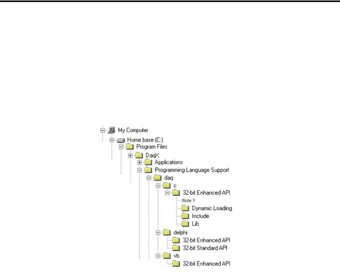
The Programming Language Support folder is located in your installation directory.
You can access program-related files from Windows Explorer.
If you used the install default directory setting, the support folder will be located under a program folder name (such as DaqX) under the Program Files folder on the C: drive. The figure below illustrates the default install location for your C/C++ and Visual Basic (VB) programming language support.
In the illustration, the 32-Bit Enhanced API folder (for C/C++ support) has been expanded to reveal its contents.
Default Install Locations for Programming Language Support
Note 1: In addition to folders labeled “Dynamic Loading,” “Include,” and “Lib,” the 32-bit Enhanced API folder includes program examples for primary data acquisition units (main units) and for DBKs.
1-2 Introduction |
908494 |
Programmer’s Manual |

Driver Installation
Driver installation uses a 32-bit setup on a Windows 95/98/Me or Windows NT/2000/XP system. When run, the setup routine will automatically detect the correct operating system and will install the appropriate driver.
A Note Regarding Devices and API Command Applicability
API commands cannot be used universally with all products. For example, a command that pertains only to analog output is of no use to a device that does not support analog I/O, or to a device that supports analog input, but not analog output. Thus it is important that you understand the features and capabilities of your hardware before using API Commands. Prior awareness can save a great deal of programming time and avoid possible frustration.
One category of functionality that sometimes causes confusion is that of waveform/pattern output. The following table indicates which of the 4 types of waveform output apply to various product groups. Waveform output definitions follow the table.
Waveform/Pattern Output Device Capabilities
Product * |
Static |
Dynamic |
Waveform |
Streamed Digital |
|
Waveform |
Waveform |
Output from |
Pattern Output |
|
|
|
Disk |
|
|
|
|
|
|
DaqBoard/500 Series |
Yes |
No |
No |
No |
|
|
|
|
|
DaqBoard/1000 Series |
Yes |
Yes |
Yes |
No |
|
|
|
|
|
DaqBoard/2000 Series |
Yes |
Yes |
Yes |
Yes |
|
|
|
|
|
DaqBook/2000 Series |
Yes |
No |
No |
No |
|
|
|
|
|
DaqLab/2000 Series |
Yes |
No |
No |
No |
|
|
|
|
|
DaqScan/2000 Series |
Yes |
No |
No |
No |
|
|
|
|
|
/3000 Series Devices |
Yes |
Yes |
Yes |
Yes |
|
|
|
|
|
*Not all devices in a series have static waveform output capability. The feature is only present for devices that have built-in DAC channel output circuitry, or if the device has a DBK46 option installed. Consult your specific hardware documentation for detailed information.
Static Waveform: Data is downloaded to the internal memory on the device and then played out from the device’s internal memory. Once the waveform output is downloaded and initiated additional output updates from the PC cannot be performed. However the waveform can be played out indefinitely from the internal memory on the device.
Dynamic Waveform: Data is downloaded to the device and can be continuously updated by the PC while the waveform output is active. Updates to the output can come from PC memory or from a file.
Programmer’s Manual |
908494 |
Introduction 1-3 |

Waveform Output from Disk: Uses dynamic waveform output to continuously update outputs from a file. The file is on a PC, which contains waveform output values, as defined by the user.
Streamed Digital Pattern Output: This output can be via P3 pins, BNC connectors, or SCSI III, depending on the device. The feature allows streaming continuous digital data to the device’s 16-bit P3 digital port [or to designated BNC connectors, if applicable]. Data can be streamed from either PC memory or from a file. The rate at which streamed output is updated is dictated by the current DAC waveform output clock source. Digital data streaming can be performed by itself or in concert with analog waveform output generation.
Become familiar with your system components prior to writing a program. Know the capabilities of each device.
TIP: Prior to writing a program, review the product specifications [found in your device hardware manual]. The specifications often make it obvious as to which API Commands could not possibly apply. In addition, the programmer needs to be aware of specification limits when entering values.
1-4 Introduction |
908494 |
Programmer’s Manual |
API Programming - General Models |
2 |
|
|
Data Acquisition Environment……2-1
Application Programming Interface (API) ……2-1
Hardware Capabilities and Constraints……2-1
Signal Environment……2-2
Seven Easy Steps to Data Acquisition …… 2-2
Models
Initialization and Error Handling……2-9
One-Step Command Acquisitions ……2-11
Counted Acquisitions Using Linear Buffers…2-12
Indefinite Acquisition, Direct-To-Disk Using Circular Buffers……2-14
Analog Output……2-16
Generating DAC FIFO Waveforms ……2-18
Digital I/O on P2……2-19
Using DBK Card Calibration Files……2-20
Zero Compensation……2-23
Linear Conversion……2-25
Reference Note:
Specific Daq Device and DBK program examples are included on the install CD.
The install CD readme.file states the location of the examples.
This chapter shows how to combine API functions to perform typical tasks. Depending on your level of programming expertise, once you understand how the API works in conjunction with the hardware you can begin creating custom data acquisition programs.
This chapter is divided into two primary sections, as follows:
•Data Acquisition Environment outlines related concepts and defines Daq device capabilities the programmer must work with (the API, hardware features, and signal management).
•The Models section explains the sequence and type of operations necessary for data acquisition. Some models are provided in Visual Basic, while others appear in C/C++ code. These models provide the software building blocks to develop more complex and specialized programs.
Data Acquisition Environment
To write effective data acquisition software, programmers must understand:
•Software tools (the API documented in this manual and the programming language—you may need to consult documentation for your chosen language)
•Hardware capabilities and constraints
•General concepts of data acquisition and signal management
Application Programming Interface (API)
The API includes all the software functions needed for building a data acquisition system with the hardware described in this manual. The API Command Reference section of this manual includes details regarding how each function is used (parameters, hardware applicability, etc). In addition, you may need to consult your language and computer documentation.
Hardware Capabilities and Constraints
To program the system effectively, you must understand your Daq device and DBK hardware capabilities. Obviously you cannot program the hardware to perform beyond its design and specifications, but you also want to take full advantage of the system’s power and features. In the User’s Manual, you may need to refer to sections that describe your hardware’s capability. In addition, you may need to consult your computer documentation. In some cases, you may need to verify the hardware setup, use of channels, and signal conditioning options (some hardware devices have jumpers and DIP switches that must match the programming, especially as the system evolves).
Programmer’s Manual |
988594 |
API Programming, General Models 2-1 |
Signal Environment
Important data acquisition concepts for programmers are listed below and are discussed in your device user’s manual.
•Channel Identification
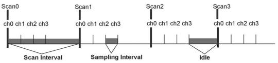
•Scan Rates and Sequencing. With multiple scans, the time between scans becomes a parameter. This time can be a constant or can be dependent upon a trigger.
•Counter/Timer Operation
•Triggering Options. Triggering starts the A/D conversion. The trigger can be an external analog or TTL trigger, or a program controlled software trigger.
Parameters in the various A/D routines include: number of channels, number of scans, start of conversion triggering, timing between scans, and mode of data transfer. Up to 512 A/D channels can be sampled in a single scan. These channels can be consecutive or nonconsecutive with the same or different gains. The scan sequence makes no distinction between local and expansion channels.
Seven Easy Steps to Data Acquisition
The sections that follow this one demonstrate various methods for designing and developing a data acquisition application. Though these models vary widely in their purpose and individually can seem quite complex most all employ a basic framework that is repeated elsewhere in other models. This section will discuss the basic framework required to develop a simple data acquisition application. The basic framework outlined here will be a re-occuring theme through most, if not all, the subsequent programming models.
Each data acquisition task can be broken down into the following basic elements:
1.Configuring Channels – What Type of Channels? How Many?
2.Configuring Acquisition Events – How Should the Acquisition Start and Stop?
3.Setting the Acquisition Rate – How Fast Should the Channels be Scanned?
4.Setting up the Buffer Model – How Should the Data be Stored?
5.Arming the Acquisition and Starting the Transfer
6.Triggering the Acquisition
7.Monitoring the Acquisition and Receiving Data
While this basic framework is not comprehensive, it does provide a basic model and a theory of operation from which to start developing your data acquisition application. Provided with each step is a description of the task and its general function, as well as representative code snippets from which an application can be developed and a table of related API functions which may be used to implement the step.
1. Configure Channels – What Type of Channels? How Many?
Every data acquisition has one or more channels from which data is to be acquired. The channels to be scanned comprise the channel scan configuration. Channels are added to the channel scan sequence in the order that they are programmed. Even if some channels are repeated in the channel scan sequence they are added to the channel scan sequence in the programmed location.
NOTE: Hereafter, the term Channel Scan (or Scan) refers to the entirety of the channel scan sequence configuration. In other words, a Channel Scan (Scan) is comprised of all the channels programmed into the channel scan sequence.
2-2 |
API Programming, General Models |
988594 |
Programmer’s Manual |
Here we are only configuring channels on the main unit. If configuring DBK expansion options each DBK channel needs to be programmed into the channel scan sequence. You may also need to set more specific channel configuration options. For this, refer to the sections regarding your specific DBK expansion card.
The following shows how to program the channel scan sequence.
DaqAdcGain |
gains[CHANCOUNT] = {DgainX1, DgainX2, DgainX8, DgainX4}; |
||
DWORD |
channels[CHANCOUNT] = {0,1,2,3}; |
||
DWORD |
flags[CHANCOUNT] = |
{DafAnalog|DafBipolar,DafAnalog|DafUnipolar, |
|
|
|
DafAnalog|DafBipolar, DafAnalog|DafUnipolar}; |
|
err = daqAdcSetScan(handle, channels, gains, flags,CHANCOUNT); |
|||
|
|
||
Related API’s* |
Description |
||
|
|
||
DaqAdcSetScan |
Performs basic channel scan sequence configuration, sets up |
||
|
|
|
channel scan information |
|
|
|
|
DaqAdcSetMux |
|
Same as daqAdcSetScan but sets all channels to the same |
|
|
|
|
configuration parameters |
|
|
||
DaqAdcSetOption |
Used to configure more complex configuration options for |
||
|
|
|
individual channels |
|
|
||
DaqAdcExpSetBank |
Used to setup channel banks/blocks for use with DBK |
||
|
|
|
expansion |
|
|
|
|
*See the API Command Reference chapter for detailed information.
2. Configure Acquisition Events – How Should the Acquisition Start and Stop?
In this section we describe how to configure the Starting and Stopping Events for your acquisition. Each acquisition needs to have well defined Start and Stop Events. A Start Event can be as simple as start the acquisition immediately upon arming. An acquisition Stop Event can be as simple as Stop upon disarming the acquisition. The number and type of start and stop events is dependent upon the capabilities of the data acquisition device and vary from product to product. Acquisitions may also be defined with pre-trigger data. The amount of pre-trigger data can vary.
err = daqAdcSetAcq(handle, DaamNShot, 0,SCANS);
err = daqSetTriggerEvent(handle,DatsSoftware, NULL,NULL,NULL,NULL,NULL, DaqStartEvent);
err = daqSetTriggerEvent(handle,DatsScanCount,NULL,NULL, NULL,NULL,NULL,NULL, DaqStopEvent);
Related API’s* |
Description |
|
|
daqAdcSetAcq |
Configures acquisition modes as well as pre and post trigger |
|
scan counts |
|
|
daqSetTriggerEvent |
Configures Start/Stop Trigger Events. |
|
|
daqAdcSetTrig |
Used to configure Start Trigger Event |
|
|
daqAdcCalcTrig |
Used to calculate Analog level in A/D counts for use in |
|
daqAdcSetTrig |
|
|
*See the API Command Reference chapter for detailed information.
Programmer’s Manual |
988594 |
API Programming, General Models 2-3 |
3. Set the Acquisition Rate – How Fast Should Channels be Scanned?
In this section we describe how to configure the rate at which data is acquired for your acquisition. Here the acquisition rate refers to the rate at which channel scans are acquired. Depending upon which API is used the acquisition scan rate can be selected by either frequency or period/interval. Note that the rate being programmed is the rate at which the entire channel scan is paced. For all Daq devices the scan pacing can be derived from either an internal clock or an external clock driven by an input controlled by an external source. The between-channel sampling interval is normally a fixed interval depending upon the type of device used. Daq devices are normally fixed at 10us sampling interval. The between-channel sampling interval for /2000 Series devices is software selectable for either 5us or 10us.
err = daqAdcSetFreq(handle, 1000.0);
Related API’s* |
Description |
|
|
daqAdcSetFreq |
Sets the acquisition rate for both pre-trigger and post-trigger |
|
acquisitions in Hz based off of the internal pacer clock of the device |
|
|
daqAdcGetFreq |
Returns the current acquisition rate setting. |
|
|
DaqAdcSetClockSource |
Sets the acquisition base clock source to either the internal pacer or |
|
to an external clock source. |
|
|
daqAdcSetRate |
Allows setting pre and post-trigger scan rates in either period or |
|
frequency format (pre-trigger rate cannot be set for most Daq |
|
device products, for Daq device products pre-trigger rate will follow |
|
post-trigger rate). This command may also be used to return |
|
current pre-trigger and post-trigger rate settings. |
|
|
*See the API Command Reference chapter for detailed information.
4. Setting up the Data Buffer Model – How Should the Data be Stored?
In this section we describe how to configure the buffer model to be used for the acquisition. There are two basic buffer models from which to choose; the User Buffer Model and the Driver Buffer Model.
The User Buffer Model allows the user or application to allocate a buffer and pass the information describing the location and disposition of the buffer down to the driver so that the driver can place collected data into the buffer. However, the User Buffer Model requires that the maintenance of the buffer and buffer pointers be performed by the user or application. When using the User Buffer Model the application can query the driver as to the total amount of data that has been transferred into the buffer but the user/application is responsible for maintaining and updating the current read and write pointers into the buffer. The User Buffer Model can employ either linear or circular buffers depending on the needs of the application.
The Driver Buffer Model the user/application to hand off responsibility of buffer management to the driver.
WORD buffer[SCANS * CHANCOUNT];
err = daqAdcTransferSetBuffer(handle, buffer,SCANS, DatmDriverBuffer);
2-4 |
API Programming, General Models |
988594 |
Programmer’s Manual |
User Buffer Model Operation
The User Buffer Model allows the user to specify either a linear buffer or circular buffer mode.
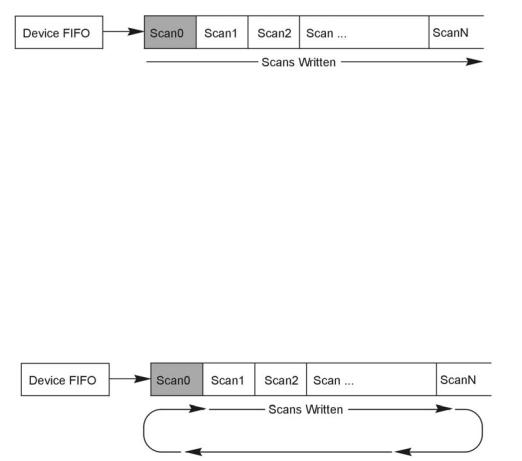
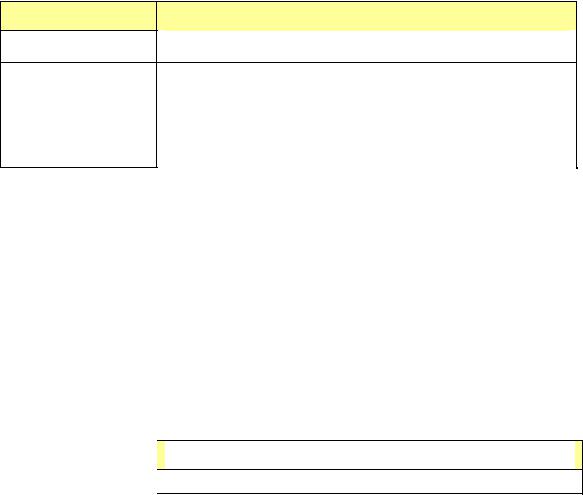
When the linear buffer mode is selected the driver will start filling the buffer from the beginning of the buffer with the newest available scans. Once the entire buffer has been filled to the number of scans specified the driver will stop writing scan data to the buffer even though the acquisition may continue.
In the User Buffer Linear mode the driver will stop writing data to the user buffer once the total number of scans requested has been satisfied. If the acquisition continues to run after this point scan data will accumulate in the device FIFO until another buffer (or the same buffer) transfer has been started or the device FIFO overruns. The implication of this is that when using linear buffers it is important to make sure that a buffer transfer remains active during the course of the acquisition or data loss may result. In other words, if the acquisition continues past the end of the specified buffer another transfer (into the same or a different buffer) must immediately be initiated. While it is possible to ping pong linear buffers in this manner it is not the recommended. Linear buffers should normally be used only when a predetermined number of scans are to be collected for the acquisition. In this case the buffer scan length should be set to to be the same size as the aggregate scan size [of the total acquisition]. For more information about starting transfers see Step 5.
The User Buffer Model also has a Circular Buffer Mode. In the circular buffer mode the driver will continue to write scan data into the User Buffer until the acquisition terminates on its own or is aborted by the user/application. Unlike the Linear Buffer model when the end of the user buffer is reached the driver will continue to write scan data starting at the beginning of the buffer.
When using the Circular Buffer mode the application does not need to make sure that there is always a buffer ready to take the scan data because the driver simply continues to fill the specified buffer and, when necessary, will begin writing data at the beginning of the buffer. This model ensures that a device FIFO overrun never occurs because the driver always has place to store the data (as long as the interface is capable of the required throughput). The application is required to monitor the transfer and remove and/or process data as it becomes available (See Step 7 on monitoring and receiving scan data). However a User Buffer overrun may occur if the controlling application cannot keep up in processing or removing the data from the buffer. Therefore the application should allocate a large enough buffer to alleviate any processing or other latencies that may be present in the system or the application. If making the buffer larger does not alleviate user buffer overrun problems then it may be necessary to upgrade the PC to a higher performance unit. The type of upgrade required will be highly dependent upon the nature of the application as well as operating environment in general. For instance, if taking data to disk then a faster HD and controller may be required. If mathematical manipulation of the data is taking place then a faster CPU may be in order. If graphics or video are used intensively then the solution may be a higher performance video card. It is important to remember that the application and other tasks within the system can have an impact on the overall performance of the data acquisition process.
Programmer’s Manual |
988594 |
API Programming, General Models 2-5 |
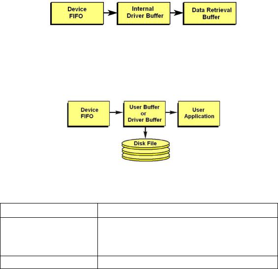
Driver Buffer Model Operation
The Driver Buffer Model allows the flexibility of the User Buffer Model in Circular mode without the complication of having to manage the circular buffer at the application level. In fact, the Buffer Model is simply a special case of the circular buffer mode in that the driver handles the details of managing the circular buffer and “hands off” scan data to the application only when the application requests it. The scan data is handed off to the application in easy to use and manipulate linear buffers.
For more information on retrieving scan data from the Driver Buffer refer to Step 7, Monitor the Acquisition and Receive the Data.
Storing Data to Disk
Either buffer model allows the data to be streamed to a disk file in parallel to the transfer into the User or Driver Buffer. To enable this the daqAdcSetDiskFile function needs to be invoked before the acquisition is armed. When using this feature the scan data can be; appended to a current file, overwrite a current file or create a new file.
With either the User Buffer Model or the Driver Buffer Model the driver performs the transfer automatically. The format of the data in the disk file being written will be the same at it appears in the buffer. This will normally be raw scan data. No header or channel configuration information is stored in the raw data file.
Related API’s* |
Description |
|
|
daqAdcTransferSetBuffer Sets up the scan data buffer for the transfer. The buffer can be configured for either User Buffer or Driver Buffer modes. When User Buffer mode is selected the buffer can be set up to be either linear or circular in nature. The size of the scan data buffer (in scans) is also set here.
daqAdcSetDiskFile |
Sets ups and enables taking the transfer scan data to a disk file. |
*See the API Command Reference chapter for detailed information.
5. Arming the Acquisition and Starting the Transfer
Once the acquisition has been completely configured the acquisition can be armed. Arming the acquisition means that device will be configured according to the previous steps already outlined and the acquisition will taken from an “idle” to an “active” state. Once in the “active” state the acquisition may begin looking for the Trigger Event or begin collecting pre-trigger data (if pre-trigger has been configured). It is important to examine error return codes from the daqAdcArm command. The daqAdcArm command examines the entire configuration for any potential acquisition parameter conflicts.
err = daqAdcTransferStart(handle); err = daqAdcArm(handle);
2-6 |
API Programming, General Models |
988594 |
Programmer’s Manual |
It is good practice to enable the transfer of data into the buffer first by calling daqAdcTransferStart command. This will ensure that a transfer is active and that the data buffer is ready to receive data so that when the acquisition is triggered the scan data can be immediately placed into the data buffer. Once the daqAdcArm command has been successfully invoked a trigger may occur at any time (obviously, once the trigger condition has been satisfied).
Related API’s*
daqAdcTransferStart
daqAdcArm
Description
Enables scan data transfer into the buffer specified by the daqAdcTransferSetBuffer command.
Arms the acquisition. This command is a pivotal command around which the entire acquisition is configured. Once invoked this command not only arms the acquisition it configures the acquisition according to the acquisition configuration parameters set by prior commands. It is here where any potential configuration conflicts are flagged. Therefore it is important to check return codes from this command.
*See the API Command Reference chapter for detailed information.
6. Triggering the Acquisition
Once the acquisition has been armed it may be triggered at any time unless a pre-trigger data has been requested. If pre-trigger data has been requested the trigger event detection will be deferred until at least the specified amount of pre-trigger data has been collected. Any trigger event that occurs before the specified pre-trigger amount has been collected will be ignored.
This deferring of the detection of the trigger event until the specified amount of pre-trigger data has been collected ensures that the acquisition will produce, at minimum, the requested pre-trigger amount.
The trigger event can be one of any valid trigger events for which the device is capable. For more information on which trigger events your device is capable of detecting please refer to the daqSetTriggerEvent command in the API definition.
Every device can be triggered via software:
err = daqAdcSoftTrig(handle);
Related API’s* |
|
Description |
|
|
|
daqAdcSoftTrig |
Triggers the acquisition if software triggering is enabled. |
|
*See the API Command Reference chapter for detailed information.
7. Monitoring the Acquisition and Receiving Data
During the acquisition it may be necessary to monitor the progress of the acquisition and to collect the data and process it. The daqAdcTransferGetStat function returns a total transfer scan count as will as acquisition and transfer state information. Interpretation of the information returned greatly depends on the the buffer model selected as well as whether or not the buffer was set to linear or circular mode operation.
DWORD active,retCount;
DaqAdcTransferGetStat(handle,&active,&retCount);
The active parameter returns state information. The individual bits returned in this parameter indicate the current state of both the acquisition and the transfer. The retCount parameter returns a total running count of the amount of data transferred thus far. The following sections show how to interpret this data:
Programmer’s Manual |
988594 |
API Programming, General Models 2-7 |
Monitoring User Buffer Model Transfers
The User Buffer Model allows the user to specify either a linear buffer or circular buffer mode.
When the linear buffer mode is selected the driver will start filling the buffer from the beginning of the buffer of size n (scans) with the newest available scans. Once the entire buffer has been filled to the number of scans specified by n the driver will stop writing scan data to the buffer even though the acquisition may continue.
For monitoring progress into a linear User Buffer, the retCount parameter will return the current location (in scans) of the write pointer. This location indicates the next scan to be written as well as representing the total number of scans acquired thus far. For instance, if retCount = m then scan0 through scanm-1 can be processed.
The User Buffer Model also has a Circular Buffer Mode. In the circular buffer mode the driver will continue to write scan data into the User Buffer until the acquisition terminates on its own or is aborted by the user/application. Unlike the Linear Buffer model when the end of the user buffer is reached the driver will continue to write scan data starting at the beginning of the buffer.
When using the Circular Buffer mode the application does not need to make sure that there is always a buffer ready to take the scan data because the driver simply continues to fill the specified buffer and, when necessary, will begin writing data at the beginning of the buffer. This model ensures that a device FIFO overrun never occurs because the driver always has place to store the data (as long as the interface is capable of the required throughput).
The application is required to monitor the transfer and remove and/or process data as it becomes available (See Step 7 on monitoring and receiving scan data). However a User Buffer overrun may occur if the controlling application cannot keep up in processing or removing the data from the buffer. Therefore the application should allocate a large enough buffer to alleviate any processing or other latencies that may be present in the system or the application.
If making the buffer larger does not alleviate user buffer overrun problems then it may be necessary to upgrade the PC to a higher performance unit. The type of upgrade required will be highly dependent upon the nature of the application as well as operating environment in general. For instance, if taking data to disk then a faster HD and controller may be required.
If mathematical manipulation of the data is taking place then a faster CPU may be in order. If graphics or video are used intensively then the solution may be a higher performance video card. It is important to remember that the application and other tasks within the system can have an impact on the overall performance of the data acquisition process.
2-8 |
API Programming, General Models |
988594 |
Programmer’s Manual |
Monitoring and Receiving Driver Buffer Model Data
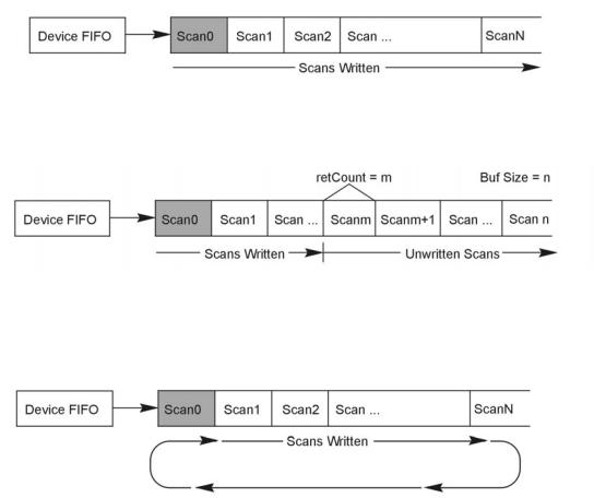
The Driver Buffer Model allows the flexibility of the User Buffer Model in Circular mode without the complication of having to manage the circular buffer at the application level. In fact, the Buffer Model is simply a special case of the circular buffer mode in that the driver handles the details of managing the circular buffer and “hands off” scan data to the application only when the application requests it. The scan data is handed off to the application in easy to use and manipulate linear buffers. Once handed off the data is removed from the Driver Buffer permanently. In other words requesting data from the Driver Buffer is a destructive read operation.
Upon request the Driver Buffer Model allows the application to request data from the internal Driver Buffer as follows:
•Return Scan Data Available Returns any unread scan data that is available in the Driver Buffer up to the requested amount. The application must ensure that it has enough space in the User Request Buffer to store any amount of unread scan data that may be present in the Driver Buffer up to the amount requested.
•Wait Until the Requested Amount is Available Waits until the requested amount is available in the Driver Buffer. When the amount of scan data available is greater than or equal to the amount requested the Driver Buffer will return the amount requested.
•Do Not Wait Until the Requested Amount is Available Upon receipt of the request if the amount of scan data available in the Driver Buffer is not greater than or equal to the amount requested then the Driver Buffer will return no scan data. If the amount requested is available at the time of the request the driver buffer will return the amount requested.
Models
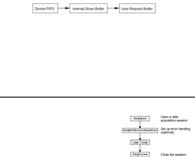
Initialization and Error Handling
This section demonstrates how to initialize the Daq device and use various methods of error handling. Most of the example programs use similar coding as detailed in the following VB example. Functions used include:
•VbdaqOpen&(daqName$)
•VbdaqSetErrorHandler&(errHandler&)
•VbdaqClose&(handle&)
All Visual Basic programs should include the DaqX.bas file into their project. The DaqX.bas file provides the necessary definitions and function prototyping for the DAQX driver DLL.
handle& = VBdaqOpen&(“DaqBook0”) ret& = VBdaqClose&(handle&)
The Daq device is opened and initialized with the daqOpen function. daqOpen takes one parameter— the name of the device to be opened. The device name can be accessed and changed via the Daq* Configuration utility located in the operating system’s Control Panel (see following figure).
Programmer’s Manual |
988594 |
API Programming, General Models 2-9 |
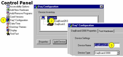
Accessing and Changing a Device Name Using the Control Panel
To change a device name by going through the Control Panel you:
(1)Go to the Control Panel and select “Daq* Configuration.
(2)Double-Click on the applicable device.
(3)Highlight the existing name and type in the new one. Then click the “OK” button, not shown.
The daqOpen call, if successful, will return a handle to the opened device. This handle may then be used by other functions to configure or perform other operations on the device. When operations with the device are complete, the device may then be closed using the daqClose function. If the device could not be found or opened, daqOpen will return -1.
The DAQX library has a default error handler defined upon loading. However; if it is desirable to change the error handler or to disable error handling, then the daqSetErrorHandler function may be used to setup an error handler for the driver. In the following example the error handler is set to 0 (no handler defined), which disables error handling.
ret& = VBdaqSetErrorHandler&(0&)
If there is a Daq device error, the program will continue. The function’s return value (an error number or 0 if no error) can help you debug a program.
If (VBdaqOpen&(“DaqBook0”) < 0) Then
“Cannot open DaqBook0”
Daq device functions return daqErrno&.
Print “daqErrno& : ”; HEX$(daqErrno&)
End If
The next statement defines an error handling routine that frees us from checking the return value of every Daq device function call. Although not necessary, this sample program transfers program control to a userdefined routine when an error is detected. Without a Daq device error handler, Visual Basic will receive and handle the error, post it on the screen and terminate the program. Visual Basic provides an integer variable (ERR) that contains the most recent error code. This variable can be used to detect the error source and take the appropriate action.
The function daqSetErrorHandler tells Visual Basic to assign ERR to a specific value when a Daq device error is encountered. The following line tells Visual Basic to set ERR to 100 when a Daq device error is encountered. (Other languages work similarly; refer to specific language documentation as needed.)
handle& = VBdaqOpen&(“DaqBook0”)
ret& = VBdaqSetErrorHandler&(handle&, 100) On Error GoTo ErrorHandler
The On Error GoTo command (in Visual Basic) allows a user-defined error handler to be provided, rather than the standard error handler that Visual Basic uses automatically. The program uses On Error GoTo to transfer program control to the label ErrorHandler if an error is encountered.
2-10 |
API Programming, General Models |
988594 |
Programmer’s Manual |
Daq device errors will send the program into the error handling routine. This is the error handler. Program control is sent here on error.
ErrorHandler:
errorString$ = "ERROR in ADC1"
errorString$ = errorString$ & Chr(10) & "BASIC Error :" + Str$(Err)
If Err = 100 Then errorString$ = errorString$ & Chr(10) & "DaqBook Error : " + Hex$(daqErrno&)
MsgBox errorString$, , "Error!" End Sub
One-Step Command Acquisitions
This section shows the use of several one-step analog input routines. These commands are easier to use than low-level commands but are less flexible in regard to scan configuration. These commands provide a single function call to configure and acquire analog input data. This example demonstrates the use of the 4 Daq device’s one-step ADC functions. Functions used include:
•VBdaqAdcRd&(handle&,chan&, sample%, gain&)
•VBdaqAdcRdN&(handle&,chan&, Buf%(), count&, trigger%, level%, freq!, gain&,flags&)
•VBdaqAdcRdScan&(handle&,startChan&, endChan&, Buf%(), gain&, flags&)
•VBdaqAdcRdScanN&(handle&,startChan&
,endChan&, Buf%(), count&, triggerSource&, level%, freq!, gain&, flags&)
This program will initialize the Daq device hardware, then take readings from the analog input channels in the base unit (not the expansion cards). For transporting data in and out of the Daq device driver, arrays are dimensioned.
Dim sample%(1), buf%(80), handle&, ret&, flags&, gain&
The following code assumes that the Daq device has been successfully opened and the handle& value is a valid handle to the device. All the following one-step functions define the channel scan groups to be analog unipolar input channels. Specifying this configuration uses the DafAnalog and the DafUnipolar values in the flags parameter. The flags parameter is a bit-mask field in which each bit specifies the characteristics of the channel(s) specified. In this case, the DafAnalog and the DafUnipolar values are added together to form the appropriate bit mask for the specified flags parameter.
The next line requests 1 reading from 1 channel with a gain of ×1. The variable DgainX1& is actually a defined constant from DaqX.bas, included at the beginning of this program.
Note: DafSigned does not work in conjunction with DaqBook/100.
ret& = VBdaqAdcRd&(handle& 0, sample%(0), DgainX1&, DafAnalog&+DafUnipolar&+DafSigned&)
Print Format$“& ####”; “Result of AdcRd:”; sample%(0)
The next line requests 10 readings from channel 0 at a gain of ×1, using immediate triggering at 1 kHz.
ret& = VBdaqAdcRdN&(handle&,0, buf%(), 10, DatsImmediate&, 0, 1000!, DgainX1&, DafAnalog&+DafUnipolar&)
Print “Results of AdcRdN: ”; For x& = 0 To 9
Print Format$ “#### ”; buf%(x&); Next x&
Programmer’s Manual |
988594 |
API Programming, General Models 2-11 |

The program will then collect one sample of channels 0 through 7 using the VBdaqAdcRdScan function.
ret& = VBdaqAdcRdScan&(handle&,0, 7, buf%(), DgainX1&, DafAnalog&+DafUnipolar&)
Print “Results of AdcRdscan:” For x& = 0 To 7
Print Format$“& # & ####”; “Channel:”; buf%(x); “Data:”; buf%(x) Next x&: Print
Counted Acquisitions Using Linear Buffers
This section sets up an acquisition that collects post-trigger A/D scans. This particular example demonstrates the setting up and collection of a fixed-length A/D acquisition in a linear buffer.
First, the acquisition is configured by setting up the channel scan group configuration, the acquisition frequency, the acquisition trigger and the acquisition mode. When configured, the acquisition is then armed by calling the daqAdcArm function.
At this point, the Daq device trigger is armed and A/D acquisition will begin upon trigger detection. If the trigger source has been configured to be DatsImmediate&, A/D data collection will begin immediately.
This example will retrieve 10 samples from channels 0 through 7, triggered immediately with a 1000 Hz sampling frequency and unity gain. Functions used include:
•VBdaqAdcSetMux&(handle&, startChan&, endChan&, gain&, flags&)
•VBdaqAdcSetFreq&(handle&,freq!)
•VBdaqAdcSetTrig&(handle&, triggerSource&, rising&, level%, hysteresis%,channel&)
•VBdaqAdcSetAcq&(handle&,mode&,preTrigCount&,postTrigCount&)
•VBdaqAdcTransferSetBuffer&(handle&,buf%(), scanCount&, transferMask&)
•VBdaqAdcTransferStart&(handle&)
•VBdaqAdcWaitForEvent&(handle&,daqEvent&)
This program will initialize the Daq device hardware, then take readings from the analog input channels in the base unit (not the expansion cards). The functions used in this program are of a lower level than those used in the previous section and provide more flexibility.
Dim buf%(80), handle&, ret&, flags&
The following function defines the channel scan group. The function specifies a channel scan group from channel 0 through 7 with all channels being analog unipolar input channels with a gain of ×1. Specifying this configuration uses DgainX1 in the gain parameter and the DafAnalog and the DafUnipolar values in the flags parameter. The flags parameter is a bit-mask field in which each bit specifies the characteristics of the specified channel(s). In this case, the DafAnalog and the DafUnipolar values are added together to form the appropriate bit mask for the specified flags parameter.
ret& = VBdaqAdcSetMux&(handle&,0, 7, DgainX1&, DafAnalog&+DafUnipolar&)
2-12 |
API Programming, General Models |
988594 |
Programmer’s Manual |
Next, set the internal sample rate to 1 kHz.
ret& = VBdaqAdcSetFreq&(handle&,1000!)
The acquisition mode needs to be configured to be fixed length acquisition with no pre-trigger scan data and 10 scans of post-trigger scan data. The mode is set to DaamNShot&, which will configure the acquisition as a fixed-length acquisition that will terminate automatically upon the satisfaction of the posttrigger count of 10.
ret& = VBdaqAdcSetAcq&(handle&,DaamNShot&, 0, 10)
The acquisition begins upon detection of the trigger event. The trigger event is configured with daqAdcSetTrig. The next line defines the trigger event (to be the immediate trigger source) that will start the acquisition immediately. The variable DatsImmediate& is a constant defined in DaqX.bas. Since the trigger source is configured as immediate, the other trigger parameters are not needed.
ret& = VBdaqAdcSetTrig&(handle&,DatsImmediate&, 0, 0, 0, 0)
A buffer now is configured to hold the A/D data to be acquired. Since this is to be a fixed length transfer to a linear buffer, the buffer cycle mode should be turned off with DatmCycleOff&. For efficiency, block update mode is specified with DatmUpdateBlock&. The buffer size is set to 10 scans.
Note: the user-defined buffer must have been allocated with sufficient storage to hold the entire transfer prior to invoking the following line.
ret& = VBdaqAdcTransferSetBuffer&(handle&,buf%(), 10, DatmUpDateBlock&+DatmCycleOff&)
With all acquisition parameters being configured, the acquisition can now be armed. Once armed, the acquisition will begin immediately upon detection of the trigger event. As in the case of the immediate trigger, the acquisition will begin immediately upon execution of the daqAdcArm function.
ret& = VBdaqAdcArm&(handle&)
After setting up and arming the acquisition, the data is immediately ready to be collected. Had the trigger source been anything other than immediate, the data would only be ready after the trigger had been satisfied. The following line initiates an A/D transfer from the Daq device to the defined user buffer.
ret& = VBdaqAdcTransferStart&(handle&)
Wait for the transfer to complete in its entirety, then proceed with normal application processing.
This can be accomplished with the daqWaitForEvent command. The daqWaitForEvent allows the application processing to become blocked until the specified event has occurred. DteAdcDone, indicates that the event to wait for is the completion of the transfer.
ret& = VBdaqWaitForEvent(handle&,DteAdcDone&)
At this point, the transfer is complete; all data from the acquisition is available for further processing.
Print “Results of Transfer”
For i& = 0 To 10
Print "Scan "; Format$(Str$(i& + 1), "00"); " -->";
For k& = k& To k& + 7
Print Format$(IntToUint&(buf%(k&)), "00000"); " ";
Next k&
Next i&
Programmer’s Manual |
988594 |
API Programming, General Models 2-13 |

Indefinite Acquisition, Direct-To-Disk Using Circular Buffers
This program demonstrates the use of circular buffers in cycle mode to collect analog input data directly to disk. In cycle mode, this data transfer can continue indefinitely. When the transfer reaches the end of the physical data array, it will reset its array pointer back to the beginning of the array and continue writing data to it. Thus, the allocated buffer can be used repeatedly like a FIFO buffer.
The API has built-in direct-to-disk functionality. Therefore, very little needs to be done by the application to configure direct-to-disk operations.
First, the acquisition is configured by setting up the channel scan group configuration, the acquisition frequency, the acquisition trigger and the acquisition mode. Once configured, the transfer to disk is set up and the acquisition is then armed by calling the daqAdcArm function.
At this point, the Daq device trigger is armed and A/D acquisition to disk will begin immediately upon trigger detection.
This example will retrieve an indefinite amount of scans for channels 0 through 7, triggered via software with a 3000 Hz sampling frequency and unity gain. Functions used include:
•VBdaqAdcSetScan&(handle&, startChan&, endChan&, gain&, flags&)
•VBdaqAdcSetFreq&(handle&,freq!)
•VBdaqAdcSetTrig&(handle&, triggerSource&, rising&, level%, hysteresis%,channel&)
•VBdaqAdcSetAcq&(handle&,mode&,preTrigCount&,postTrigCount&)
•VBdaqAdcTransferSetBuffer&(handle&,buf%(), scanCount&, transferMask&)
•VBdaqAdcTransferStart&(handle&)
•VBdaqAdcTransferGetStat&(handle&,status&,retCount&)
•VBdaqAdcWaitForEvent&(handle&,daqEvent&)
•VBdaqAdcSetDiskFile&(handle&,filename$,openMode&,preWrite&)
This program will initialize the Daq device hardware, then take readings from the analog input channels in the base unit (not the expansion cards) and store them to disk automatically. The following lines demonstrate channel scan group configuration using the daqAdcSetScan command.
Note: flags may be channel-specific.
2-14 |
API Programming, General Models |
988594 |
Programmer’s Manual |
Dim handle&, |
ret&, channels&(8), |
gains&(8) flags&(8) |
|
Dim |
buf%(80000), active&, count& |
‘ In scans |
|
Dim |
bufsize& |
= 10000 |
|
'Define arrays of channels and gains : 0-7 , unity gain For x& = 0 To 7
channels&(x&) = x& gains&(x&) = DgainX1&
flags&(x&) = DafAnalog& + DafSingleEnded& + DafUnipolar& Next x&
'Load scan sequence FIFO
ret& = VBdaqAdcSetScan&(handle&,channels&(), gains&(), flags&(), 8)
Next, set the internal sample rate to 3 kHz.
ret& = VBdaqAdcSetFreq&(handle&,3000!)
The acquisition mode needs to be configured to be fixed-length acquisition with no pre-trigger scan data and 10 scans of post-trigger scan data. The mode is set to DaamInfinitePost&, which will configure the acquisition as having indefinite length and, as such, will be terminated by the application. In this mode, the preand post-trigger count values are ignored.
ret& = VBdaqAdcSetAcq&(handle&,DaamInfinitePost&, 0, 0)
The acquisition begins upon detection of the trigger event. The trigger event is configured with daqAdcSetTrig. The next line defines the trigger event to be the immediate trigger source which will start the acquisition immediately. The variable DatsSoftware& is a constant defined in DaqX.bas. Since the trigger source is configured as immediate, the other trigger parameters are not needed.
ret& = VBdaqAdcSetTrig&(handle&,DatsSoftware&, 0, 0, 0, 0)
A buffer now is configured to hold the A/D data to be acquired. This buffer is necessary to hold incoming A/D data while it is being prepared for disk I/O. Since this is to be an indefinite-length transfer to a circular buffer, the buffer cycle mode should be turned on with DatmCycleOn&. For efficiency, block update mode is specified with DatmUpdateBlock&. The buffer size is set to 10,000 scans. The buffer size indicates only the size of the circular buffer, not the total number of scans to be taken.
ret& = VBdaqAdcTransferSetBuffer&(handle&,buf%(), bufsize&, DatmUpDateBlock&+DatmCycleOn&)
Now the destination disk file is configured and opened. For this example, the disk file is a new file to be created by the driver. After the following line has been executed, the specified file will be opened and ready to accept data.
ret& = VBdaqAdcSetDiskFile&(handle&,”c:dasqdata.bin”, DaomCreateFile&, 0)
With all acquisition parameters being configured and the acquisition transfer to disk configured, the acquisition can now be armed. Once armed, the acquisition will begin immediately upon detection of the trigger event. As in the case of the immediate trigger, the acquisition will begin immediately upon execution of the daqAdcArm function.
ret& = VBdaqAdcArm&(handle&)
After setting up and arming the acquisition, data collection will begin upon satisfaction of the trigger event. Since the trigger source is software, the trigger event will not take place until the application issues the software trigger event. To prepare for the trigger event, the following line initiates an A/D transfer from the Daq device to the defined user buffer and, subsequently, to the specified disk file. No data is transferred at this point, however.
ret& = VBdaqAdcTransferStart&(handle&)
The transfer has been initiated, but no data will be transferred until the trigger event occurs. The following line will signal the software trigger event to the driver; then A/D input data will be transferred to the specified disk file as it is being collected.
ret& = VBdaqAdcSoftTrig&(handle&)
Programmer’s Manual |
988594 |
API Programming, General Models 2-15 |
Both the acquisition and the transfer are now currently active. The transfer to disk will continue indefinitely until terminated by the application. The application can monitor the transfer process with the following lines of code:
acqTermination& = 0 Do
‘ Wait here for new data to arrive
ret& = VBdaqWaitForEvent(handle&,DteAdcData&)
‘ New data has been transferred - Check status
ret& = VBdaqAdcTransferGetStat&(handle&,active&,retCount&)
‘Code may be placed here which will process the buffered data or
‘perform other application activities
‘
‘At some point the application needs to determine the event on which
‘the direct-to-disk acquisition is to be halted and set the
‘acqTermination flag.
Loop While acqTermination& = 0
At this point the application is ready to terminate the acquisition to disk. The following line will terminate the acquisition to disk and will close the disk file.
ret& = VBdaqAdcDisarm&(handle&)
The acquisition as well as the data transfer has been stopped. We should check status one more time to get the total number of scans actually transferred to disk.
ret& = VBdaqAdcTransferGetStat(handle&,active&,retCount&)
The specified disk file is now available. The retCount& parameter will indicate the total number of scans transferred to disk.
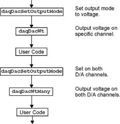
Analog Output
The program DACEX1.BAS shows how to output analog voltages on analog output channels 0 and 1. These commands only have to be issued one time unless a related parameter is explicity changed. The output voltages will be sustained. This example demonstrates the use of the two digital-to- analog converters (values used assume bipolar mode). Functions used include:
•VBdaqDacSetOutputMode&(ha ndle&, DddtLocal&, 0, DdomVoltage&)
•VBdaqDacWt&(handle&, deviceType&, chan&, dataVal%)
•VBdaqDacWtMany&(handle,
deviceTypes&(),chans&(),
dataVals&())
2-16 |
API Programming, General Models |
988594 |
Programmer’s Manual |
Assuming the voltage reference is connected to the internal default of 5 V, the next function will set channel 0 to an output voltage of 5 V. The values are set for a digital-to-analog converter with 16 bit resolution; 65535 represents full-scale. Channel 1 is equal to 0.
ret& = VBdaqDacSetOutputMode&(handle&, DddtLocal&, 0, DdomVoltage&) ret& = VBdaqDacWt&(handle&, DddtLocal, 0, 65535)
The daqDacWtMany writes to both analog outputs simultaneously. The following lines sets channel 0 to 5 V and channel 1 to 2.5 V. At full-scale, a digital value of 65535 corresponds to 5 V; a digital value of 49152 corresponds to ½ of 5 V.
Dim deviceTypes&(1) Dim chans&(1)
Dim dataVals%(1)
The VBdaqSetOutputMode puts the channel in a voltage mode.
ret& = VBdaqSetOutputMode&(handle&, DddtLocal&, 0, DdomVoltage&) ret& = VBdaqSetOutputMode&(handle&, DddtLocal&, 1, DdomVoltage&) deviceTypes&(0) = DddtLocal&
deviceTypes&(1) = DddtLocal& chans&(0) = 0
chans&(1) = 1 dataVals&(0) = 65535 dataVals&(1) = 49152
ret& = VBdaqDacWtMany&(handle&, deviceTypes&(), chans&(), dataVals&(),2)
The following sets the outputs to 0 V.
Dim deviceTypes&(1) Dim chans&(1)
Dim dataVals%(1) deviceTypes&(0) = DddtLocal& deviceTypes&(1) = DddtLocal& chans&(0) = 0
chans&(1) = 1 dataVals&(0) = 32768 dataVals&(1) = 32768
ret& = VBdaqDacSetOutputMode&(handle&, DddtLocal&, 0, DdomVoltage&) ret& = VBdaqDacSetOutputMode&(handle&, DddtLocal&, 1, DdomVoltage&) ret& = VBdaqDacWtMany&(handle&, deviceTypes&(), chans&(), dataVals&(),2)
Programmer’s Manual |
988594 |
API Programming, General Models 2-17 |

Generating DAC FIFO Waveforms
This program demonstrates the use of the DAC FIFO to generate waveforms. The DAC is configured for output on both channels, and the user waveform is constructed. Output begins after the waveform is assigned to a channel. At this point, the program continues while the waveforms are generated.
The following example shows how to generate a pre-defined waveform using these functions:
•VBdaqDacWaveSetTrig&(handle&, deviceType&, chan&, triggerSource&, rising%)
•VBdaqDacWaveSetClockSource&(handle&, deviceType&, chan&, clockSource&)
•VBdaqDacWaveSetFreq&(handle&, deviceType&, chan&, freq!)
•VBdaqDacWaveSetMode&(handle&, deviceType&, chan&, mode&, updateCount&)
•VBdaqDacWaveSetBuffer&(handle&, deviceType&, chan&, buf%(), scanCount&, transferMask&)
•VBdaqDacWaveSetPredefWave&(handle&, deviceType&, chan&, waveType&, amplitude&, offset&, dutyCycle&, phaseShift&)
•VBdaqDacWaveArm&(ByVal handle&, ByVal deviceType&)
When using the pre-defined waveform generation, program the waveform parameters common to both channels. The double star (**) indicates the value must be the same on both channels of a DaqBoard.
For chan = 0 To 1 Step 1
' set the output mode to static waveform
ret& = VBdaqDacSetOutputMode&(handle&, DddtLocal&, chan&, DdomStaticWave&)
' The trigger source must be set to immediate for static waveform.**
err& = VBdaqDacWaveSetTrig&(handle&, DddtLocal&, chan&, DdtsImmediate&, 1)
' set the internal dac clock
ret& = VBdaqDacWaveSetClockSource&(handle&, DddtLocal&, chan&, DdcsDacClock&)
' the frequency of the internal clock. **
ret& = VBdaqDacWaveSetFreq&(handle&, DddtLocal&, chan&, 10!)
' must be infinite for static mode
ret& = VBdaqDacWaveSetMode&(handle&, DddtLocal&, chan&, DdwmInfinite&, 0) Next chan
'buffer cylce on, retransmit mode. **
'update count is the buffer length. **
ret& = VBdaqDacWaveSetBuffer&(handle&, DddtLocal&, chan&, buf0%(), updateCount&, DdtmCycleOn&)
' set the buffer for channel 1 |
|
buf1%(), |
||
ret& = VBdaqDacWaveSetBuffer&(handle&, DddtLocal&, chan&, |
||||
updateCount&, DdtmCycleOn&) |
|
|
||
' program the waveform parameters specific |
to dac channel |
0 |
||
ret& = VBdaqDacWaveSetPredefWave&(handle&, |
DddtLocal&, 0, |
DdwtTriangle&, |
||
32768, 32768, |
90, |
0) |
|
|
' program the waveform parameters specific |
to dac channel |
1 |
||
ret& = VBdaqDacWaveSetPredefWave&(handle&, |
DddtLocal&, 1, |
DdwtSquare&, |
||
32768, 32768, |
40, |
0) |
|
|
'buffer must be configured before the arm command is called. All channels
'will be armed.
ret& = VBdaqDacWaveArm(handle&, DddtLocal&)
2-18 |
API Programming, General Models |
988594 |
Programmer’s Manual |
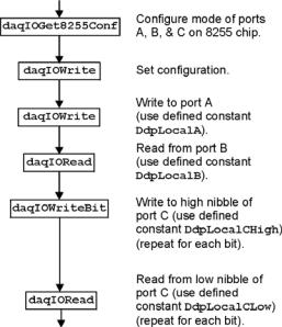
Digital I/O on P2
This program demonstrates the functions controlling digital I/O on the P2 connector of the device. First, the 3 digital ports on the 8255 are configured as input, output, or both in the case of port C; then, appropriate I/O commands are issued. Functions used include:
•VBdaqIOReadBit&(handle&, devType&, devPort&, whichDevice&, whichExpPort&, bitNum&, bitValue&)
•VBdaqIORead&(handle&, devType&, devPort&, whichDevice&, whichExpPort&, value&)
•VBdaqIOWriteBit&(handle&, devType&, devPort&, whichDevice&, whichExpPort&, bitNum&, bitValue&)
•VBdaqIOWrite&(handle&, devType&, devPort&, whichDevice&, whichExpPort&, value&)
•VBdaqIOGet8255Conf&(handle&, portA&, portB&, portCHigh&, portCLow&, config&)
Dim config&, byteVal&, bitVal&, x%
Dim buf(10) As Byte, active&, retCount& handle& = VBdaqOpen&(“DaqBook0”)
ret& = VBdaqSetErrorHandler&(handle&, 100) On Error GoTo ErrorHandlerDIG1
ret& = VBdaqIOGet8255Conf&(handle&, 0, 1, 0, 1, config&)
The function daqIOGet8255Conf returns the appropriate configuration value to use in daqIOWrite. As shown above, the handle of the opened Daq device is the first parameter passed. The second, third, fourth, and fifth parameters respectively indicate: the 8255 port A value, the port B value, the high-nibble value of port C, and the low-nibble value of port C. The values for the parameters passed in the call shown above will return the configuration value (port A = OUTPUT, port B = INPUT, port C / high nibble = output, port C / low nibble = INPUT) in the config& parameter, which matches the current configuration of the 8255.
The daqIOWrite function writes the obtained configuration value to the selected port.
ret& = VBdaqIOWrite&(handle&, DiodtLocal8255&, Diodp8255IR&, 0, 0,_ config&)
Write hex 55 to port A on the Daq device’s base unit.
ret& = VBdaqIOWrite&(handle&, DiodtLocal8255&, Diodp8255A&, 0, 0,_ &H55)
Read port B and put the value into the variable byteVal%.
ret& = VBdaqIORead&(handle&, DiodtLocal8255&, Diodp8255B&, 0, 0,_ byteVal&) Print "The value on digital port B : &H"; Hex$(byteVal&): Print
The following lines write to the high nibble of port C.
ret& = VBdaqIOWriteBit&(handle&,DiodtLocal8255&,Diodp8255CHigh&,0,_ 0,0,1) ret& = VBdaqIOWriteBit&(handle&,DiodtLocal8255&,Diodp8255CHigh&,0,_ 0,1, 0) ret& = VBdaqIOWriteBit&(handle&,DiodtLocal8255&,Diodp8255CHigh&,0,_ 0, 2, 1) ret& = VBdaqIOWriteBit&(handle&,DiodtLocal8255&,Diodp8255CHigh&,0,_ 0, 3, 0) Print "The high nibble of digital port C set to : 0101 (&H5)": Print
The next lines read the low nibble of port C on the base unit.
Programmer’s Manual |
988594 |
API Programming, General Models 2-19 |

For |
x% = 0 To 3 |
Diodp8255CLow&, |
ret& |
= VBdaqIOReadBit&(handle&, DiodtLocal8255&,_ |
|
0, 0, x%, bitVal&) |
Hex$(bitVal&) |
|
Print "The value on bit "; x%; " of digital port C : &H";_ |
||
Next x% |
|
|
Using DBK Card Calibration Files
Software calibration functions are designed to adjust Daq device readings to compensate for gain and offset errors. Calibration constants are calculated at the factory by measuring the gain and offset errors of a card at each programmable gain setting. These constants are stored in a calibration text file that can be read by a program at runtime. This allows new boards to be configured for calibration by updating this calibration file rather than recompiling the program. Calibration constants and instructions are shipped with the related DBK boards. Programs like DaqView support this calibration and use the same constants.
The calibration operation removes static gain and offset errors that are inherent in the hardware. The calibration constants are measured at the factory and do not change during the execution of a program. These constants are different for each card and programmable-gain setting; they may even be different for each channel, depending on the design of the expansion card.
Note: DBK19 is shipped with calibration constants. Other cards use on-board potentiometers to perform hardware calibration.
The calibration process has 3 steps:
•Initialization consists of reading the calibration file.
•Setup describes the characteristics of the data to be calibrated.
•Conversion does the actual calibration of the data.
[MAIN]
32760,32769
32801,32750
32740,32777
32810,32768
[EXP3]
32780,32779
32800,32756
32768,32780
32750,32742
[EXP5]
32752,32764
32783,32757
32749,32767
32777,32730
Function prototypes, return error codes, and parameter definitions are located in the DAQX.H header file for C (or similar files for other languages).
Cards that support the calibration functions are shipped with a diskette containing a calibration constants file. The name of the file will be the serial number of the card shipped with it. This file holds the calibration constants for each programmablegain setting of that card. These constants should be copied to a calibration text file (DAQBOOK.CAL) located in the same directory as the program performing the calibration.
To set up the calibration file, perform the following steps:
2-20 |
API Programming, General Models |
988594 |
Programmer’s Manual |
Loading...