

Page 1

Programmer’s Manual
Producing Custom Software for Data Acquisition Systems
IOtech
25971 Cannon Road
Cleveland, OH 44146-1833
Phone: (440) 439-4091
E-mail (Product Information): sales@iotech.com
E-mail (Technical Support): productsupport@iotech.com
Programmer’s Manual
Producing Custom Software
for Data Acquisition Systems
p/n 1008-0901 Rev. 10.4
Fax: (440) 439-4093
Internet: www.iotech.com
*372195A-01*
372195A-01
© 2003 through 2007 by IOtech 958293
Page 2

Documents Related to Daq Products
Note: During software installation, Adobe® PDF versions of user’s manuals will
automatically install onto your hard drive as a part of product support. The
default location is in the Programs group, which can be accessed from the
Windows Desktop. Initial navigation is as follows:
Start [Desktop “Start” pull-down menu]
⇒ Programs
⇒ IOtech DaqX Software
You can also access the PDF documents directly from the data acquisition CD
by using the <View PDFs> button located on the opening screen.
Refer to the PDF documentation for details regarding hardware and software
pertinent to your data acquisition system.
®
A copy of the Adobe Acrobat Reader
provides a means of reading and printing the PDF documents. Note that
hardcopy versions of the manuals can be ordered from the factory.
is included on your CD. The Reader
Page 3

How to use this Manual
This manual is for individuals who write their own programs. If you prefer to use existing out-of-the box
software such as DaqView, ViewXL, DASYLab, SnapMaster, you do not need to read this manual.
This manual explains how to program data acquisition systems using various APIs. The programming
languages used in the examples are C/C++ and Visual Basic. In addition to the information in this manual,
you need to refer to your hardware user’s manual. It may be helpful to read the DaqView user’s manual to
appreciate how a user-friendly data acquisition system looks from the user’s point of view. You may also
need to consult documentation pertaining to your specific computer system and programming environment.
In regard to this manual, you should read chapter 1, and then refer to additional chapters that are relevant to
your programming environment.
The manual is organized as follows:
1. Introduction - The manual begins with an overview of issues related to data acquisition
programming and takes a look at the options available for making the task as easy as possible.
2. API Programming – General Models – discusses aspects of the data acquisition environment,
provides several API models and a summary of selected API functions. The chapter includes a
section entitled, Seven Easy Steps to Data Acquisition.
3. Using Multiple Devices
4. Daq API Command Reference
Appendix A – Appendix Removed. Outdated material.
Appendix B, Using Borland C++
Appendix C, Custom OEM Installation, explains the procedures required for custom reseller hardware
and driver installation and distribution.
Appendix D, daq9513… Commands, this appendix only applies to DaqBook/100 Series, DaqBook/200
Series, DaqBoard/100 Series and DaqBoard/200 Series devices. The appendix includes an
API programming model for 9513 counter-timer chip devices and includes API reference
material for the daq9513… command prototypes.
®
Note:
During software installation, Adobe
PDF versions of user manuals will automatically
install onto your hard drive as a part of product support. The default location is in the
Programs directory, which can be accessed from the Windows Desktop. Refer to the
PDF documentation for details regarding both hardware and software.
®
A copy of the Adobe Acrobat Reader
is included on your CD. The Reader provides
a means of reading and printing the PDF documents. Note that hardcopy versions of
the manuals can be ordered from the factory.
Reference Note: The readme.file on your install CD-ROM identifies the location of
program examples that are included on the CD.
Programmer’s Manual 908494 vii
Page 4

This page is intentionally blank.
viii 908494 Programmer’s Manual
Page 5

Table of Contents
1- Introduction
API Features......1-1
Language Support......1-2
Driver Installation......1-2
A Note Regarding API Command
Applicability …… 1-3
2- API Programming - General Models
Data Acquisition Environment……2-1
Application Programming Interface (API) ……2-1
Hardware Capabilities and Constraints……2-1
Signal Environment……2-2
Seven Easy Steps to Data Acquisition …… 2-2
Models
Initialization and Error Handling……2-9
One-Step Command Acquisitions ……2-11
Counted Acquisitions Using Linear Buffers…2-12
Indefinite Acquisition, Direct-To-Disk Using
Circular Buffers……2-14
Analog Output……2-16
Generating DAC FIFO Waveforms …2-18
Digital I/O on P2……2-19
Using DBK Card Calibration Files……2-20
Zero Compensation……2-23
Linear Conversion……2-25
4 - API Command Reference
Overview …… 4.1-1
Command Information Layout......4.1-2
Predefined Parameter Definitions......4.1-4
Mask and Flag Definitions......4.1-6
Setting/Constructing Mask & Flag Values....4.1-6
Reading/Interpreting Mask & Flag Values....4.1-7
API Commands
Alphabetic Listing......4.1-8
Grouped by Function......4.1-9
The API Commands, In Detail......4.1-13
API Error Codes......4.7-1
Appendix A – Removed, Outdated Material
Appendix B – Using Borland C++
Appendix C – Custom OEM Installation
Appendix D – daq9513… Commands
3- Using Multiple Devices
Overview…… 3-1
Asynchronous Operation ……3-1
Synchronous Operation ……3-1
Asynchronous Operation of Multiple
Devices …… 3-1
Synchronous Operation of Multiple
Devices ……3-3
Internal Clock Method…… 3-4
Master Clock Method…… 3-5
External Clock Method……3-7
Reference Note:
The readme.file on your install CD provides the location of program examples that are included on the CD.
Glossary
Programmer’s Manual 908494 ix
Page 6

This page is intentionally blank.
x 908494 Programmer’s Manual
Page 7

Introduction 1
API Features...... 1-1
Language Support...... 1-2
Driver Installation...... 1-2
A Note Regarding Devices and API Command Applicability …… 1-3
Reference Note:
Your companion user’s manual discusses hardware installation and setup, theory of
operation, troubleshooting, and ready-to-run software. If you plan to use DaqView software
[shipped with Daq device products], or you plan to use other ready-to-run software such as
DASYLab or SnapMaster, you will not need to use this manual.
Programmers can use the Applications Program Interface (API) to customize software. To
create effective programs, programmers must be familiar with the hardware and operation as
described in the previous chapters of this document.
Note: The readme files on the install CD-ROM will keep you up-to-date as APIs continue to
evolve.
Note: Daq PCMCIA is not supported under Windows95/NT drivers.
This manual serves both novice and experienced programmers.
• As a tutorial - The Programming Models chapter explains how to combine commands to
do useful work in a typical data acquisition environment. Program excerpts illustrate
concepts and can be modified as needed to use in your programs.
• As a reference – A great portion of the manual pertains to API commands. API
Reference Note:
This manual contains no computer programming tutorials.
You may need to consult additional documentation.
API Features
The install CD-ROM includes several “drivers” to accommodate various programming
environments.
The API has several features:
• Multi-device - can concurrently handle up to 4 devices of the Daq device family
• Larger buffer - can handle up to 2 billion samples at a time
• Enhanced acquisition and trigger modes
• Direct-to-disk capabilities
• Wait-on-event features
• Uses multi-tasking advantages of Windows 95/98/Me/NT/2000/XP
definitions and parameter values are important to ensure proper syntax, and that
software functions perform as intended.
Programmer’s Manual 908494 Introduction 1-1
Page 8
Language Support
The following three languages are supported:
C/C++ Visual Basic
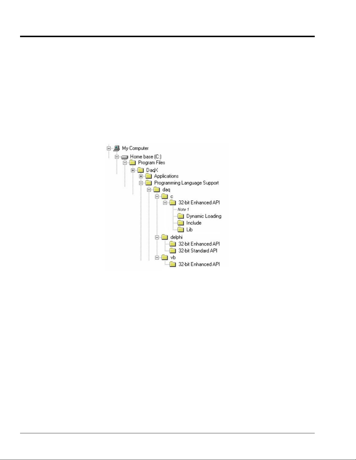
The Programming Language Support folder is located in your installation directory.
You can access program-related files from Windows Explorer.
If you used the install default directory setting, the support folder will be located under a program
folder name (such as DaqX) under the Program Files folder on the C: drive. The figure below
illustrates the default install location for your C/C++ and Visual Basic (VB) programming language
support.
In the illustration, the 32-Bit Enhanced API folder (for C/C++ support) has been expanded to reveal
its contents.
Default Install Locations for Programming Language Support
Note 1: In addition to folders labeled “Dynamic Loading,” “Include,” and “Lib,”
the 32-bit Enhanced API folder includes program examples for primary
data acquisition units (main units) and for DBKs.
1-2 Introduction 908494 Programmer’s Manual
Page 9
Driver Installation
Driver installation uses a 32-bit setup on a Windows 95/98/Me or Windows NT/2000/XP
system. When run, the setup routine will automatically detect the correct operating system
and will install the appropriate driver.
A Note Regarding Devices and API Command Applicability
API commands cannot be used universally with all products. For example, a command that
pertains only to analog output is of no use to a device that does not support analog I/O, or to
a device that supports analog input, but not analog output. Thus it is important that you
understand the features and capabilities of your hardware before using API Commands. Prior
awareness can save a great deal of programming time and avoid possible frustration.
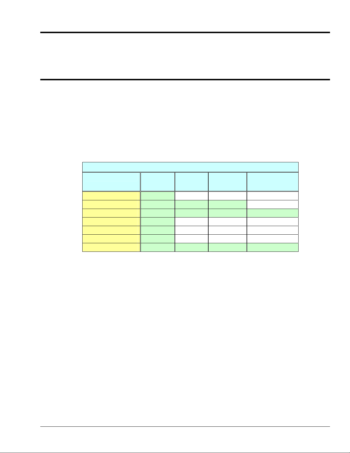
One category of functionality that sometimes causes confusion is that of waveform/pattern
output. The following table indicates which of the 4 types of waveform output apply to various
product groups. Waveform output definitions follow the table.
Waveform/Pattern Output Device Capabilities
Product * Static
DaqBoard/500 Series Yes No No No
DaqBoard/1000 Series Yes Yes Yes No
DaqBoard/2000 Series Yes Yes Yes Yes
DaqBook/2000 Series Yes No No No
DaqLab/2000 Series Yes No No No
DaqScan/2000 Series Yes No No No
/3000 Series Devices Yes Yes Yes Yes
Waveform
* Not all devices in a series have static waveform output capability. The feature is only
present for devices that have built-in DAC channel output circuitry, or if the device has
a DBK46 option installed.
Consult your specific hardware documentation for detailed
information.
Static Waveform: Data is downloaded to the internal memory on the device and then played
out from the device’s internal memory. Once the waveform output is downloaded and
initiated additional output updates from the PC cannot be performed. However the waveform
can be played out indefinitely from the internal memory on the device.
Dynamic Waveform: Data is downloaded to the device and can be continuously updated by
the PC while the waveform output is active. Updates to the output can come from PC memory
or from a file.
Dynamic
Waveform
Waveform
Output from
Disk
Streamed Digital
Pattern Output
Programmer’s Manual 908494 Introduction 1-3
Page 10

Waveform Output from Disk: Uses dynamic waveform output to continuously update
outputs from a file. The file is on a PC, which contains waveform output values, as defined by
the user.
Streamed Digital Pattern Output: This output can be via P3 pins, BNC connectors, or SCSI
III, depending on the device. The feature allows streaming continuous digital data to the
device’s 16-bit P3 digital port [or to designated BNC connectors, if applicable]. D ata can be
streamed from either PC memory or from a file. The rate at which streamed output is updated
is dictated by the current DAC waveform output clock source. Digital data streaming can be
performed by itself or in concert with analog waveform output generation.
Become familiar with your system components prior to writing a
program. Know the capabilities of each device.
TIP: Prior to writing a program, review the product specifications [found
in your device hardware manual]. The specifications often make it
obvious as to which API Commands could not possibly apply. In
addition, the programmer needs to be aware of specification limits when
entering values.
1-4 Introduction 908494 Programmer’s Manual
Page 11

API Programming - General Models 2
Data Acquisition Environment……2-1
Application Programming Interface (API) ……2-1
Hardware Capabilities and Constraints……2-1
Signal Environment……2-2
Seven Easy Steps to Data Acquisition …… 2-2
Models
Initialization and Error Handling……2-9
One-Step Command Acquisitions ……2-11
Counted Acquisitions Using Linear Buffers…2-12
Indefinite Acquisition, Direct-To-Disk Using Circular Buffers……2-14
Analog Output……2-16
Generating DAC FIFO Waveforms ……2-18
Digital I/O on P2……2-19
Using DBK Card Calibration Files……2-20
Zero Compensation……2-23
Linear Conversion……2-25
Reference Note:
Specific Daq Device and DBK program examples are included on the install CD.
The install CD readme.file states the location of the examples.
This chapter shows how to combine API functions to perform typical tasks. Depending on your
level of programming expertise, once you understand how the API works in conjunction with
the hardware you can begin creating custom data acquisition programs.
This chapter is divided into two primary sections, as follows:
• Data Acquisition Environment outlines related concepts and defines Daq device
capabilities the programmer must work with (the API, hardware features, and signal
management).
• The Models section explains the sequence and type of operations necessary for data
acquisition. Some models are provided in Visual Basic, while others appear in C/C++
code. These models provide the software building blocks to develop more complex
and specialized programs.
Data Acquisition Environment
To write effective data acquisition software, programmers must understand:
• Software tools (the API documented in this manual and the programming language—you
may need to consult documentation for your chosen language)
• Hardware capabilities and constraints
• General concepts of data acquisition and signal management
Application Programming Interface (API)
The API includes all the software functions needed for building a data acquisition system with
the hardware described in this manual. The API Command Reference section of this manual
includes details regarding how each function is used (parameters, hardware applicability, etc).
In addition, you may need to consult your language and computer documentation.
Hardware Capabilities and Constraints
To program the system effectively, you must understand your Daq device and DBK hardware
capabilities. Obviously you cannot program the hardware to perform beyond its design and
specifications, but you also want to take full advantage of the system’s power and features.
In the User’s Manual, you may need to refer to sections that describe your hardware’s
capability. In addition, you may need to consult your computer documentation. In some
cases, you may need to verify the hardware setup, use of channels, and signal conditioning
options (some hardware devices have jumpers and DIP switches that must match the
programming, especially as the system evolves).
Programmer’s Manual 988594 API Programming, General Models 2-1
Page 12

Signal Environment
Important data acquisition concepts for programmers are listed below and are discussed in
your device user’s manual.
• Channel Identification
• Scan Rates and Sequencing. With multiple scans, the time between scans becomes a
parameter. This time can be a constant or can be dependent upon a trigger.
• Counter/Timer Operation
• Triggering Options. Triggering starts the A/D conversion. The trigger can be an
external analog or TTL trigger, or a program controlled software trigger.
Parameters in the various A/D routines include: number of channels, number of scans, start of
conversion triggering, timing between scans, and mode of data transfer. Up to 512 A/D
channels can be sampled in a single scan. These channels can be consecutive or nonconsecutive with the same or different gains. The scan sequence makes no distinction
between local and expansion channels.
Seven Easy Steps to Data Acquisition
The sections that follow this one demonstrate various methods for designing and developing a
data acquisition application. Though these models vary widely in their purpose and
individually can seem quite complex most all employ a basic framework that is repeated
elsewhere in other models. This section will discuss the basic framework required to develop a
simple data acquisition application. The basic framework outlined here will be a re-occuring
theme through most, if not all, the subsequent programming models.
Each data acquisition task can be broken down into the following basic elements:
1. Configuring Channels – What Type of Channels? How Many?
2. Configuring Acquisition Events – How Should the Acquisition Start and Stop?
3. Setting the Acquisition Rate – How Fast Should the Channels be Scanned?
4. Setting up the Buffer Model – How Should the Data be Stored?
5. Arming the Acquisition and Starting the Transfer
6. Triggering the Acquisition
7. Monitoring the Acquisition and Receiving Data
While this basic framework is not comprehensive, it does provide a basic model and a theory
of operation from which to start developing your data acquisition application. Provided with
each step is a description of the task and its general function, as well as representative code
snippets from which an application can be developed and a table of related API functions
which may be used to implement the step.
1. Configure Channels – What Type of Channels? How Many?
Every data acquisition has one or more channels from which data is to be acquired. The
channels to be scanned comprise the channel scan configuration. Channels are added to the
channel scan sequence in the order that they are programmed. Even if some channels are
repeated in the channel scan sequence they are added to the channel scan sequence in the
programmed location.
NOTE: Hereafter, the term Channel Scan (or Scan) refers to the entirety of the channel scan
sequence configuration. In other words, a Channel Scan (Scan) is comprised of all the
channels programmed into the channel scan sequence.
2-2 API Programming, General Models 988594 Programmer’s Manual
Page 13
Here we are only configuring channels on the main unit. If configuring DBK expansion options
each DBK channel needs to be programmed into the channel scan sequence. You may also
need to set more specific channel configuration options. For this, refer to the sections
regarding your specific DBK expansion card.
The following shows how to program the channel scan sequence.
DaqAdcGain gains[CHANCOUNT] = {DgainX1, DgainX2, DgainX8, DgainX4};
DWORD channels[CHANCOUNT] = {0,1,2,3};
DWORD flags[CHANCOUNT] = {DafAnalog|DafBipolar,DafAnalog|DafUnipolar,
DafAnalog|DafBipolar, DafAnalog|DafUnipolar};
err = daqAdcSetScan(handle, channels, gains, flags,CHANCOUNT);
Related API’s* Description
DaqAdcSetScan
DaqAdcSetMux
DaqAdcSetOption
DaqAdcExpSetBank
*See the API Command Reference chapter for detailed information.
Performs basic channel scan sequence configuration, sets up
channel scan information
Same as daqAdcSetScan but sets all channels to the same
configuration parameters
Used to configure more complex configuration options for
individual channels
Used to setup channel banks/blocks for use with DBK
expansion
2. Configure Acquisition Events – How Should the Acquisition Start and Stop?
In this section we describe how to configure the Starting and Stopping Events for your
acquisition. Each acquisition needs to have well defined Start and Stop Events. A Start Event
can be as simple as start the acquisition immediately upon arming. An acquisition Stop Event
can be as simple as Stop upon disarming the acquisition. The number and type of start and
stop events is dependent upon the capabilities of the data acquisition device and vary from
product to product. Acquisitions may also be defined with pre-trigger data. The amount of
pre-trigger data can vary.
err = daqAdcSetAcq(handle, DaamNShot, 0,SCANS);
err = daqSetTriggerEvent(handle,DatsSoftware, NULL,NULL,NULL,NULL,NULL,
DaqStartEvent);
err = daqSetTriggerEvent(handle,DatsScanCount,NULL,NULL,
NULL,NULL,NULL,NULL, DaqStopEvent);
Related API’s* Description
daqAdcSetAcq
daqSetTriggerEvent
daqAdcSetTrig
daqAdcCalcTrig
*See the API Command Reference chapter for detailed information.
Configures acquisition modes as well as pre and post trigger
scan counts
Configures Start/Stop Trigger Events.
Used to configure Start Trigger Event
Used to calculate Analog level in A/D counts for use in
daqAdcSetTrig
Programmer’s Manual 988594 API Programming, General Models 2-3
Page 14

3. Set the Acquisition Rate – How Fast Should Channels be Scanned?
In this section we describe how to configure the rate at which data is acquired for your
acquisition. Here the acquisition rate refers to the rate at which channel scans are acquired.
Depending upon which API is used the acquisition scan rate can be selected by either
frequency or period/interval. Note that the rate being programmed is the rate at which the
entire channel scan is paced. For all Daq devices the scan pacing can be derived from either
an internal clock or an external clock driven by an input controlled by an external source. The
between-channel sampling interval is normally a fixed interval depending upon the type of
device used. Daq devices are normally fixed at 10us sampling interval. The between-channel
sampling interval for /2000 Series devices is software selectable for either 5us or 10us.
err = daqAdcSetFreq(handle, 1000.0);
Related API’s* Description
daqAdcSetFreq
daqAdcGetFreq
DaqAdcSetClockSource
daqAdcSetRate
*See the API Command Reference chapter for detailed information.
Sets the acquisition rate for both pre-trigger and post-trigger
acquisitions in Hz based off of the internal pacer clock of the device
Returns the current acquisition rate setting.
Sets the acquisition base clock source to either the internal pacer or
to an external clock source.
Allows setting pre and post-trigger scan rates in either period or
frequency format (pre-trigger rate cannot be set for most Daq
device products, for Daq device products pre-trigger rate will follow
post-trigger rate). This command may also be used to return
current pre-trigger and post-trigger rate settings.
4. Setting up the Data Buffer Model – How Should the Data be Stored?
In this section we describe how to configure the buffer model to be used for the acquisition.
There are two basic buffer models from which to choose; the User Buffer Model and the Driver
Buffer Model.
The User Buffer Model allows the user or application to allocate a buffer and pass the
information describing the location and disposition of the buffer down to the driver so that the
driver can place collected data into the buffer. However, the User Buffer Model requires that
the maintenance of the buffer and buffer pointers be performed by the user or application.
When using the User Buffer Model the application can query the driver as to the total amount
of data that has been transferred into the buffer but the user/application is responsible for
maintaining and updating the current read and write pointers into the buffer. The User Buffer
Model can employ either linear or circular buffers depending on the needs of the application.
The Driver Buffer Model the user/application to hand off responsibility of buffer management
to the driver.
WORD buffer[SCANS * CHANCOUNT];
err = daqAdcTransferSetBuffer(handle, buffer,SCANS, DatmDriverBuffer);
2-4 API Programming, General Models 988594 Programmer’s Manual
Page 15
User Buffer Model Operation
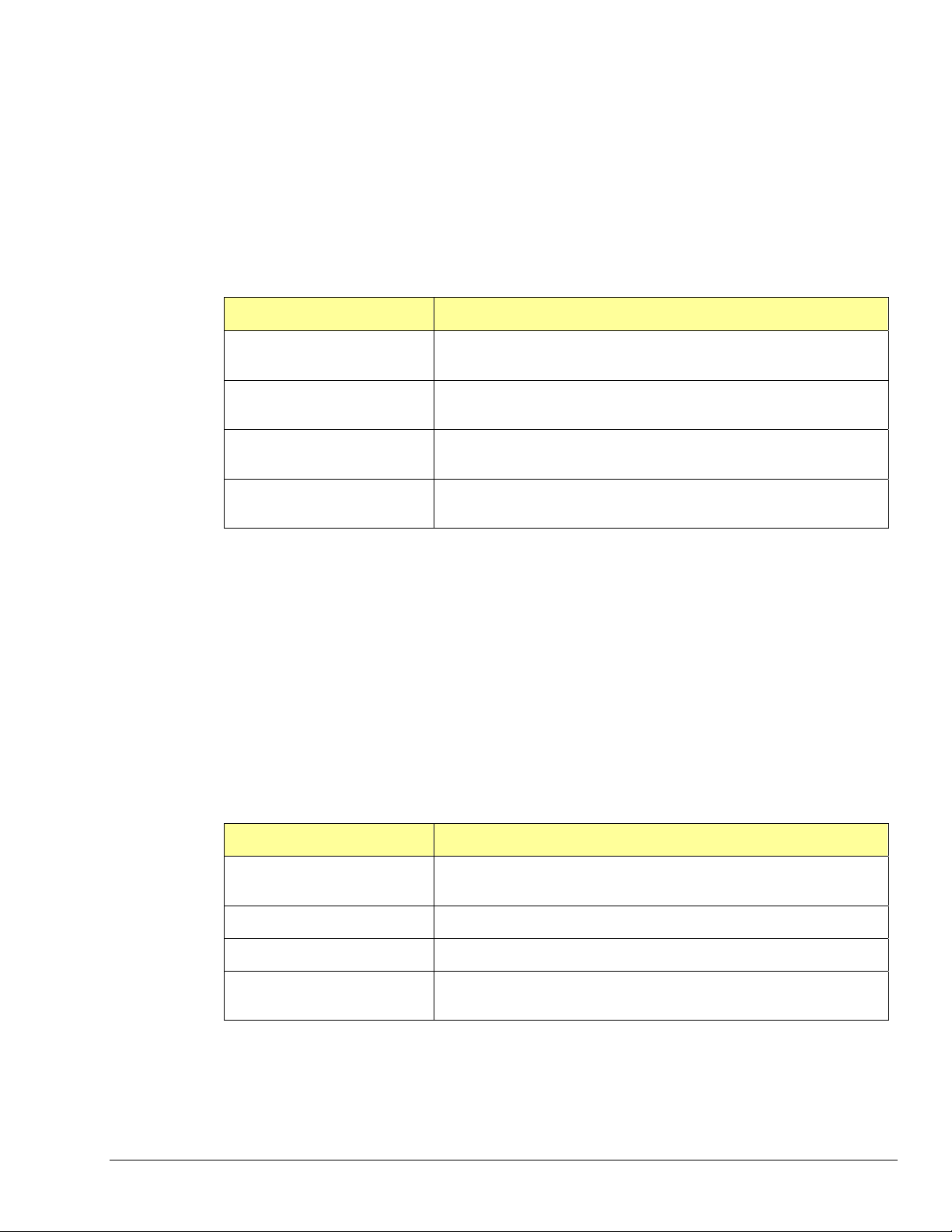
The User Buffer Model allows the user to specify either a linear buffer or circular buffer mode.
When the linear buffer mode is selected the driver will start filling the buffer from the
beginning of the buffer with the newest available scans. Once the entire buffer has been filled
to the number of scans specified the driver will stop writing scan data to the buffer even
though the acquisition may continue.
In the User Buffer Linear mode the driver will stop writing data to the user buffer once the
total number of scans requested has been satisfied. If the acquisition continues to run after
this point scan data will accumulate in the device FIFO until another buffer (or the same
buffer) transfer has been started or the device FIFO overruns. The implication of this is that
when using linear buffers it is important to make sure that a buffer transfer remains active
during the course of the acquisition or data loss may result. In other words, if the acquisition
continues past the end of the specified buffer another transfer (into the same or a different
buffer) must immediately be initiated. While it is possible to ping pong linear buffers in this
manner it is not the recommended. Linear buffers should normally be used only when a
predetermined number of scans are to be collected for the acquisition. In this case the buffer
scan length should be set to to be the same size as the aggregate scan size [of the total
acquisition]. For more information about starting transfers see Step 5.
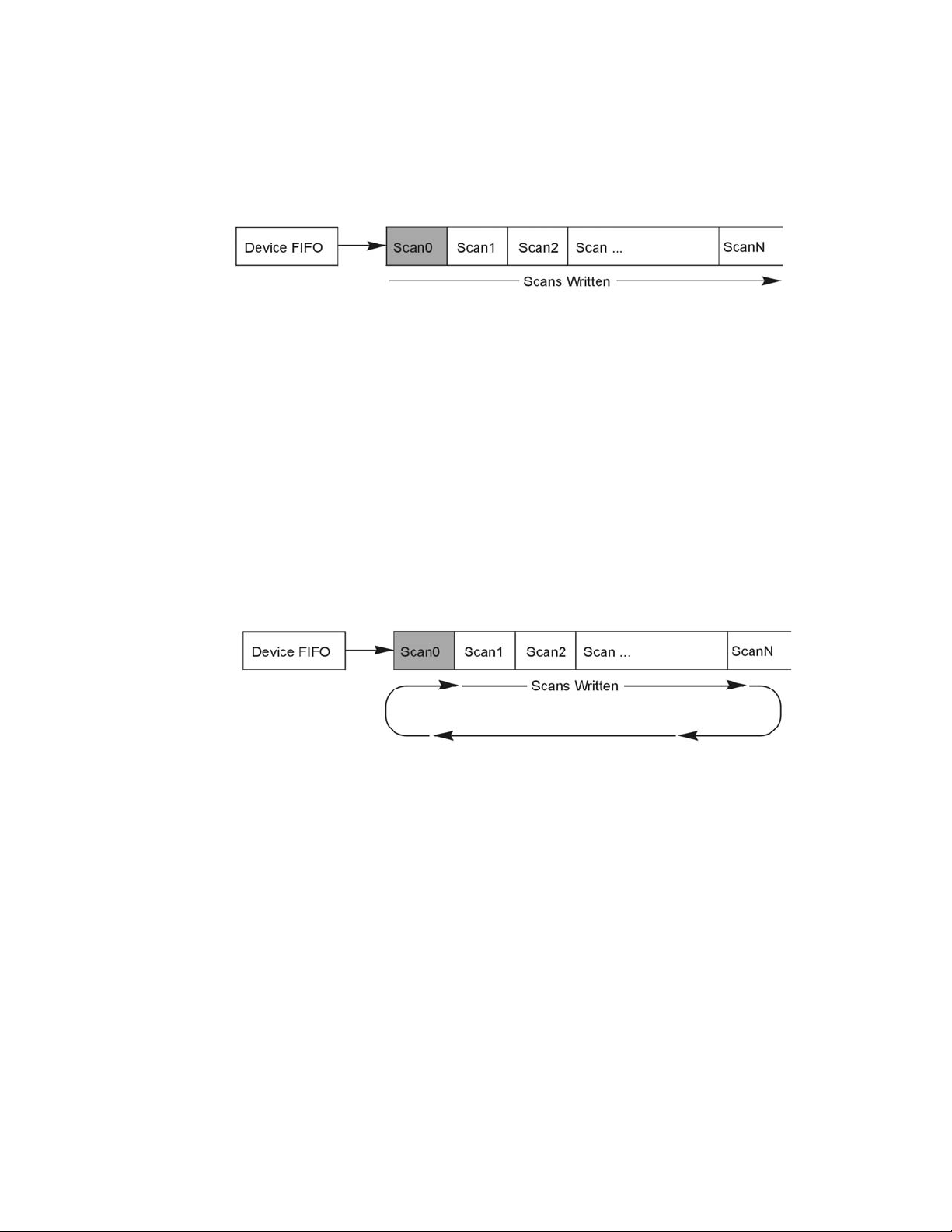
The User Buffer Model also has a Circular Buffer Mode. In the circular buffer mode the driver
will continue to write scan data into the User Buffer until the acquisition terminates on its own
or is aborted by the user/application. Unlike the Linear Buffer model when the end of the user
buffer is reached the driver will continue to write scan data starting at the beginning of the
buffer.
When using the Circular Buffer mode the application does not need to make sure that there is
always a buffer ready to take the scan data because the driver simply continues to fill the
specified buffer and, when necessary, will begin writing data at the beginning of the buffer.
This model ensures that a device FIFO overrun never occurs because the driver always has
place to store the data (as long as the interface is capable of the required throughput). The
application is required to monitor the transfer and remove and/or process data as it becomes
available (See Step 7 on monitoring and receiving scan data). However a User Buffer overrun
may occur if the controlling application cannot keep up in processing or removing the data
from the buffer. Therefore the application should allocate a large enough buffer to alleviate
any processing or other latencies that may be present in the system or the application. If
making the buffer larger does not alleviate user buffer overrun problems then it may be
necessary to upgrade the PC to a higher performance unit. The type of upgrade required will
be highly dependent upon the nature of the application as well as operating environment in
general. For instance, if taking data to disk then a faster HD and controller may be required.
If mathematical manipulation of the data is taking place then a faster CPU may be in order. If
graphics or video are used intensively then the solution may be a higher performance video
card. It is important to remember that the application and other tasks within the system can
have an impact on the overall performance of the data acquisition process.
Programmer’s Manual 988594 API Programming, General Models 2-5
Page 16
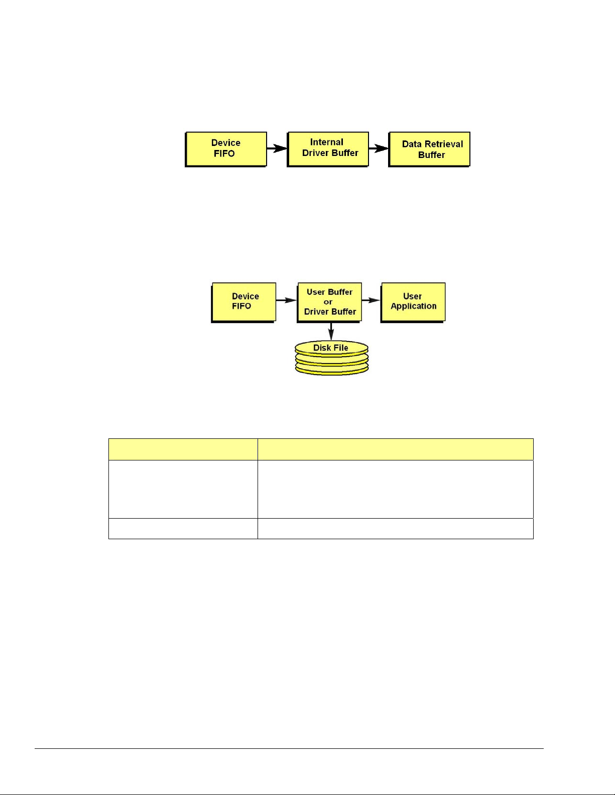
Driver Buffer Model Operation
The Driver Buffer Model allows the flexibility of the User Buffer Model in Circular mode without
the complication of having to manage the circular buffer at the application level. In fact, the
Buffer Model is simply a special case of the circular buffer mode in that the driver handles the
details of managing the circular buffer and “hands off” scan data to the application only when
the application requests it. The scan data is handed off to the application in easy to use and
manipulate linear buffers.
For more information on retrieving scan data from the Driver Buffer refer to Step 7, Monitor
the Acquisition and Receive the Data.
Storing Data to Disk
Either buffer model allows the data to be streamed to a disk file in parallel to the transfer into
the User or Driver Buffer. To enable this the daqAdcSetDiskFile function needs to be invoked
before the acquisition is armed. When using this feature the scan data can be; appended to a
current file, overwrite a current file or create a new file.
With either the User Buffer Model or the Driver Buffer Model the driver performs the transfer
automatically. The format of the data in the disk file being written will be the same at it
appears in the buffer. This will normally be raw scan data. No header or channel configuration
information is stored in the raw data file.
Related API’s* Description
daqAdcTransferSetBuffer
daqAdcSetDiskFile
Sets up the scan data buffer for the transfer. The buffer can be
configured for either User Buffer or Driver Buffer modes. When
User Buffer mode is selected the buffer can be set up to be
either linear or circular in nature. The size of the scan data
buffer (in scans) is also set here.
Sets ups and enables taking the transfer scan data to a disk file.
*See the API Command Reference chapter for detailed information.
5. Arming the Acquisition and Starting the Transfer
Once the acquisition has been completely configured the acquisition can be armed. Arming
the acquisition means that device will be configured according to the previous steps already
outlined and the acquisition will taken from an “idle” to an “active” state. Once in the “active”
state the acquisition may begin looking for the Trigger Event or begin collectin g pre-trigger
data (if pre-trigger has been configured). It is important to examine error return codes from
the daqAdcArm command. The daqAdcArm command examines the entire configuration for
any potential acquisition parameter conflicts.
err = daqAdcTransferStart(handle);
err = daqAdcArm(handle);
2-6 API Programming, General Models 988594 Programmer’s Manual
Page 17
It is good practice to enable the transfer of data into the buffer first by calling daqAdcTransferStart
command. This will ensure that a transfer is active and that the data buffer is ready to receive data so
that when the acquisition is triggered the scan data can be immediately placed into the data buffer. Once
the daqAdcArm command has been successfully invoked a trigger may occur at any time (obviously, once
the trigger condition has been satisfied).
Related API’s* Description
daqAdcTransferStart
Enables scan data transfer into the buffer specified by the
daqAdcTransferSetBuffer command.
daqAdcArm
Arms the acquisition. This command is a pivotal command around
which the entire acquisition is configured. Once invoked this
command not only arms the acquisition it configures the
acquisition according to the acquisition configuration parameters
set by prior commands. It is here where any potential
configuration conflicts are flagged. Therefore it is important to
check return codes from this command.
*See the API Command Reference chapter for detailed information.
6. Triggering the Acquisition
Once the acquisition has been armed it may be triggered at any time unless a pre-trigger data
has been requested. If pre-trigger data has been requested the trigger event detection will be
deferred until at least the specified amount of pre-trigger data has been collected. Any trigger
event that occurs before the specified pre-trigger amount has been collected will be ignored.
This deferring of the detection of the trigger event until the specified amount of pre-trigger
data has been collected ensures that the acquisition will produce, at minimum, the requested
pre-trigger amount.
The trigger event can be one of any valid trigger events for which the device is capable. For
more information on which trigger events your device is capable of detecting please refer to
the daqSetTriggerEvent command in the API definition.
Every device can be triggered via software:
err = daqAdcSoftTrig(handle);
Related API’s* Description
daqAdcSoftTrig
Triggers the acquisition if software triggering is enabled.
*See the API Command Reference chapter for detailed information.
7. Monitoring the Acquisition and Receiving Data
During the acquisition it may be necessary to monitor the progress of the acquisition and to
collect the data and process it. The daqAdcTransferGetStat function returns a total transfer
scan count as will as acquisition and transfer state information. Interpretation of the
information returned greatly depends on the the buffer model selected as well as whether or
not the buffer was set to linear or circular mode operation.
DWORD active,retCount;
DaqAdcTransferGetStat(handle,&active,&retCount);
The active parameter returns state information. The individual bits returned in this parameter
indicate the current state of both the acquisition and the transfer. The retCount parameter
returns a total running count of the amount of data transferred thus far. The following
sections show how to interpret this data:
Programmer’s Manual 988594 API Programming, General Models 2-7
Page 18
Monitoring User Buffer Model Transfers
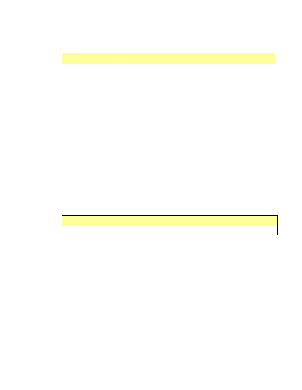
The User Buffer Model allows the user to specify either a linear buffer or circular buffer mode.
When the linear buffer mode is selected the driver will start filling the buffer from the
beginning of the buffer of size n (scans) with the newest available scans. Once the entire
buffer has been filled to the number of scans specified by n the driver will stop writing scan
data to the buffer even though the acquisition may continue.
For monitoring progress into a linear User Buffer, the retCount parameter will return the
current location (in scans) of the write pointer. This location indicates the next scan to be
written as well as representing the total number of scans acquired thus far. For instance, if
retCount = m then scan0 through scanm-1 can be processed.
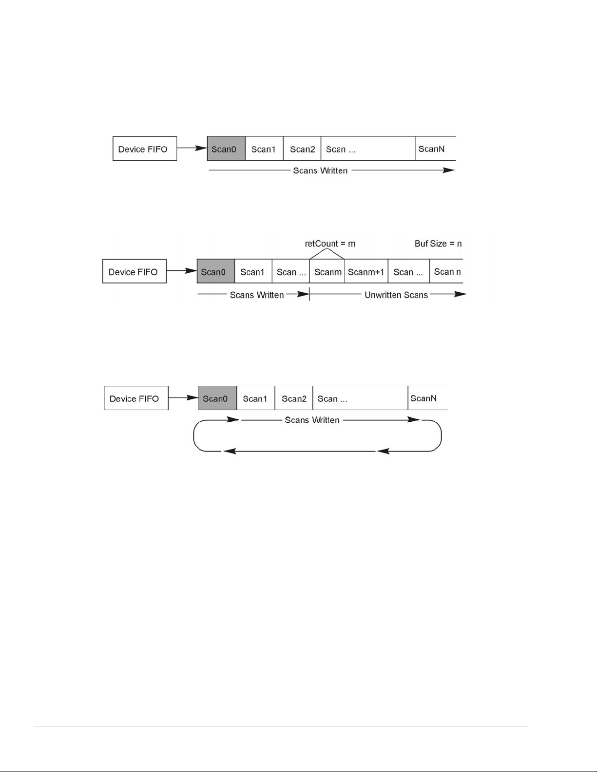
The User Buffer Model also has a Circular Buffer Mode. In the circular buffer mode the driver
will continue to write scan data into the User Buffer until the acquisition terminates on its own
or is aborted by the user/application. Unlike the Linear Buffer model when the end of the user
buffer is reached the driver will continue to write scan data starting at the beginning of the
buffer.
When using the Circular Buffer mode the application does not need to make sure that there is
always a buffer ready to take the scan data because the driver simply continues to fill the
specified buffer and, when necessary, will begin writing data at the beginning of the buffer.
This model ensures that a device FIFO overrun never occurs because the driver always has
place to store the data (as long as the interface is capable of the required throughput).
The application is required to monitor the transfer and remove and/or process data as it
becomes available (See Step 7 on monitoring and receiving scan data). However a User
Buffer overrun may occur if the controlling application cannot keep up in processing or
removing the data from the buffer. Therefore the application should allocate a large enough
buffer to alleviate any processing or other latencies that may be present in the system or the
application.
If making the buffer larger does not alleviate user buffer overrun problems then it may be
necessary to upgrade the PC to a higher performance unit. The type of upgrade required will
be highly dependent upon the nature of the application as well as operating environment in
general. For instance, if taking data to disk then a faster HD and controller may be required.
If mathematical manipulation of the data is taking place then a faster CPU may be in order. If
graphics or video are used intensively then the solution may be a higher performance video
card. It is important to remember that the application and other tasks within the system can
have an impact on the overall performance of the data acquisition process.
2-8 API Programming, General Models 988594 Programmer’s Manual
Page 19
Monitoring and Receiving Driver Buffer Model Data
The Driver Buffer Model allows the flexibility of the User Buffer Model in Circular mode without
the complication of having to manage the circular buffer at the application level. In fact, the
Buffer Model is simply a special case of the circular buffer mode in that the driver handles the
details of managing the circular buffer and “hands off” scan data to the application only when
the application requests it. The scan data is handed off to the application in easy to use and
manipulate linear buffers. Once handed off the data is removed from the Driver Buffer
permanently. In other words requesting data from the Driver Buffer is a destructive read
operation.
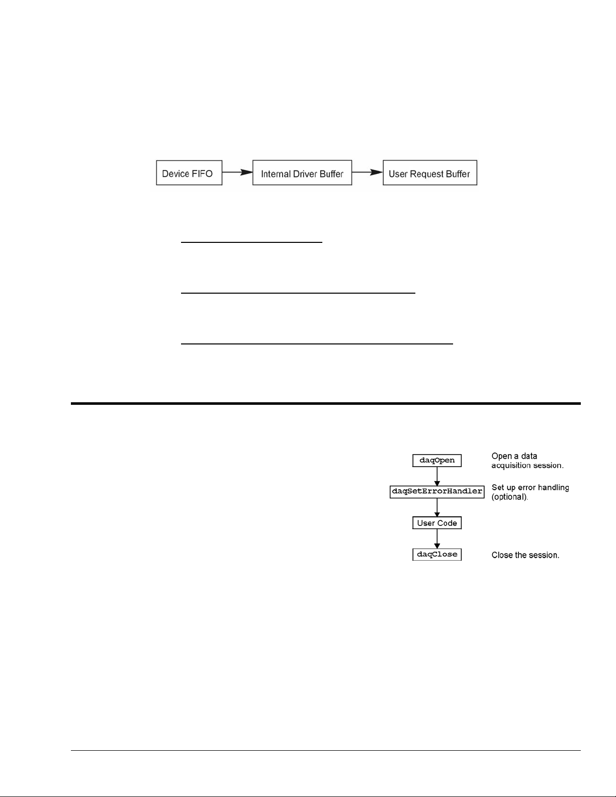
Upon request the Driver Buffer Model allows the application to request data from the internal
Driver Buffer as follows:
• Return Scan Data Available Returns any unread scan data that is available in the
Driver Buffer up to the requested amount. The application must ensure that it has
enough space in the User Request Buffer to store any amount of unread scan data that
may be present in the Driver Buffer up to the amount requested.
• Wait Until the Requested Amount is Available Waits until the requested amount
is available in the Driver Buffer. When the amount of scan data available is greater
than or equal to the amount requested the Driver Buffer will return the amount
requested.
• Do Not Wait Until the Requested Amount is Available Upon receipt of the request
if the amount of scan data available in the Driver Buffer is not greater than or equal to
the amount requested then the Driver Buffer will return no scan data. If the amount
requested is available at the time of the request the driver buffer will return the
amount requested.
Models
Initialization and Error Handling
This section demonstrates how to initialize the Daq
device and use various methods of error handling. Most
of the example programs use similar coding as detailed in
the following VB example. Functions used include:
• VbdaqOpen&(daqName$)
• VbdaqSetErrorHandler&(errHandler&)
• VbdaqClose&(handle&)
All Visual Basic programs should include the DaqX.bas
file into their project. The DaqX.bas file provides the
necessary definitions and function prototyping for the
DAQX driver DLL.
handle& = VBdaqOpen&(“DaqBook0”)
ret& = VBdaqClose&(handle&)
The Daq device is opened and initialized with the
daqOpen function. daqOpen takes one parameter—
the name of the device to be opened. The device name can be accessed and changed via the Daq*
Configuration utility located in the operating system’s Control Panel (see following figure).
Programmer’s Manual 988594 API Programming, General Models 2-9
Page 20
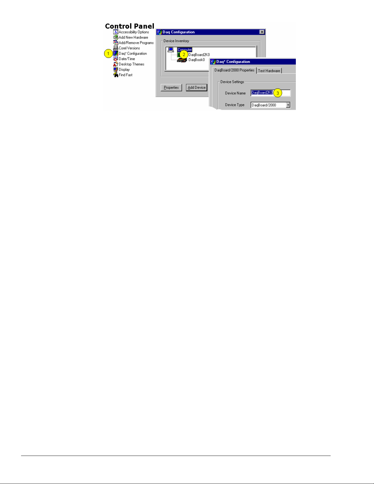
Accessing and Changing a Device Name Using the Control Panel
To change a device name by going through the Control Panel you:
(1) Go to the Control Panel and select “Daq* Configuration.
(2) Double-Click on the applicable device.
(3) Highlight the existing name and type in the new one. Then click the “OK” button, not shown.
daqOpen call, if successful, will return a handle to the opened device. This handle may then be used
The
by other functions to configure or perform other operations on the device. When operations with the
device are complete, the device may then be closed using the
be found or opened,
daqOpen will return -1.
daqClose function. If the device could not
The DAQX library has a default error handler defined upon loading. However; if it is desirable to change
the error handler or to disable error handling, then the
setup an error handler for the driver. In the following example the error handler is set to
daqSetErrorHandler function may be used to
0 (no handler
defined), which disables error handling.
ret& = VBdaqSetErrorHandler&(0&)
If there is a Daq device error, the program will continue. The function’s return value (an error number or 0
if no error) can help you debug a program.
If (VBdaqOpen&(“DaqBook0”) < 0) Then
“Cannot open DaqBook0”
Daq device functions return daqErrno&.
Print “daqErrno& : ”; HEX$(daqErrno&)
End If
The next statement defines an error handling routine that frees us from checking the return value of every
Daq device function call. Although not necessary, this sample program transfers program control to a userdefined routine when an error is detected. Without a Daq device error handler, Visual Basic will receive
and handle the error, post it on the screen and terminate the program. Visual Basic provides an integer
variable (ERR) that contains the most recent error code. This variable can be used to detect the error
source and take the appropriate action.
The function
daqSetErrorHandler tells Visual Basic to assign ERR to a specific value when a Daq
device error is encountered. The following line tells Visual Basic to set ERR to 100 when a Daq device
error is encountered. (Other languages work similarly; refer to specific language documentation as
needed.)
handle& = VBdaqOpen&(“DaqBook0”)
ret& = VBdaqSetErrorHandler&(handle&, 100)
On Error GoTo ErrorHandler
The On Error GoTo command (in Visual Basic) allows a user-defined error handler to be provided,
rather than the standard error handler that Visual Basic uses automatically. The program uses
to transfer program control to the label ErrorHandler if an error is encountered.
GoTo
2-10 API Programming, General Models 988594 Programmer’s Manual
On Error
Page 21

Daq device errors will send the program into the error handling routine. This is the error h andler. Program
control is sent here on error.
ErrorHandler:
errorString$ = "ERROR in ADC1"
errorString$ = errorString$ & Chr(10) & "BASIC Error :" + Str$(Err)
If Err = 100 Then errorString$ = errorString$ & Chr(10) & "DaqBook Error
: " + Hex$(daqErrno&)
MsgBox errorString$, , "Error!"
End Sub
One-Step Command Acquisitions
This section shows the use of several one-step analog
input routines. These commands are easier to use than
low-level commands but are less flexible in regard to
scan configuration. These commands provide a single
function call to configure and acquire analog input data.
This example demonstrates the use of the 4 Daq device’s
one-step ADC functions. Functions used include:
• VBdaqAdcRd&(handle&,chan&, sample%,
gain&)
• VBdaqAdcRdN&(handle&,chan&, Buf%(),
count&, trigger%, level%, freq!,
gain&,flags&)
• VBdaqAdcRdScan&(handle&,startChan&,
endChan&, Buf%(), gain&, flags&)
• VBdaqAdcRdScanN&(handle&,startChan&
, endChan&, Buf%(), count&,
triggerSource&, level%, freq!,
gain&, flags&)
This program will initialize the Daq device hardware,
then take readings from the analog input channels in the
base unit (not the expansion cards). For transporting data
in and out of the Daq device driver, arrays are
dimensioned.
Dim sample%(1), buf%(80), handle&,
ret&, flags&, gain&
The following code assumes that the Daq device has been successfully opened and the
handle& value is a
valid handle to the device. All the following one-step functions define the channel scan groups to be
analog unipolar input channels. Specifying this configuration uses the
values in the
characteristics of the channel(s) specified. In this case, the
flags parameter. The flags parameter is a bit-mask field in which each bit specifies the
DafAnalog and the DafUnipolar values are
added together to form the appropriate bit mask for the specified
The next line requests 1 reading from 1 channel with a gain of ×1. The variable
DafAnalog and the DafUnipolar
flags parameter.
DgainX1& is actually a
defined constant from DaqX.bas, included at the beginning of this program.
Note:
DafSigned does not work in conjunction with DaqBook/100.
ret& = VBdaqAdcRd&(handle& 0, sample%(0), DgainX1&,
DafAnalog&+DafUnipolar&+DafSigned&)
Print Format$“& ####”; “Result of AdcRd:”; sample%(0)
The next line requests 10 readings from channel 0 at a gain of ×1, using immediate triggering at 1 kHz.
ret& = VBdaqAdcRdN&(handle&,0, buf%(), 10, DatsImmediate&, 0, 1000!,
DgainX1&, DafAnalog&+DafUnipolar&)
Print “Results of AdcRdN: ”;
For x& = 0 To 9
Print Format$ “#### ”; buf%(x&);
Next x&
Programmer’s Manual 988594 API Programming, General Models 2-11
Page 22
The program will then collect one sample of channels 0 through 7 using the VBdaqAdcRdScan function.
ret& = VBdaqAdcRdScan&(handle&,0, 7, buf%(), DgainX1&,
DafAnalog&+DafUnipolar&)
Print “Results of AdcRdscan:”
For x& = 0 To 7
Print Format$“& # & ####”; “Channel:”; buf%(x); “Data:”; buf%(x)
Next x&: Print
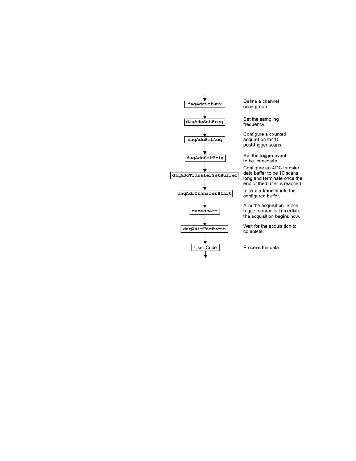
Counted Acquisitions Using Linear Buffers
This section sets up an acquisition that
collects post-trigger A/D scans. This
particular example demonstrates the setting
up and collection of a fixed-length A/D
acquisition in a linear buffer.
First, the acquisition is configured by
setting up the channel scan group
configuration, the acquisition frequency,
the acquisition trigger and the acquisition
mode. When configured, the acquisition is
then armed by calling the
function.
At this point, the Daq device trigger is
armed and A/D acquisition will begin upon
trigger detection. If the trigger source has
been configured to be
A/D data collection will begin
immediately.
daqAdcArm
DatsImmediate&,
This example will retrieve 10 samples from
channels 0 through 7, triggered
immediately with a 1000 Hz sampling
frequency and unity gain. Functions used
include:
• VBdaqAdcSetMux&(handle&, startChan&, endChan&, gain&, flags&)
• VBdaqAdcSetFreq&(handle&,freq!)
• VBdaqAdcSetTrig&(handle&, triggerSource&, rising&, level%,
hysteresis%,channel&)
• VBdaqAdcSetAcq&(handle&,mode&,preTrigCount&,postTrigCount&)
• VBdaqAdcTransferSetBuffer&(handle&,buf%(), scanCount&, transferMask&)
• VBdaqAdcTransferStart&(handle&)
• VBdaqAdcWaitForEvent&(handle&,daqEvent&)
This program will initialize the Daq device hardware, then take readings from the analog input channels in
the base unit (not the expansion cards). The functions used in this program are of a lower level than those
used in the previous section and provid e more flexibility.
Dim buf%(80), handle&, ret&, flags&
The following function defines the channel scan group. The function specifies a channel scan group from
channel 0 through 7 with all channels being analog unipolar input channels with a gain of ×1. Specifying
this configuration uses
flags parameter. The flags parameter is a bit-mask field in which each bit specifies the
in the
characteristics of the specified channel(s). In this case, the
added together to form the appropriate bit mask for the specified
ret& = VBdaqAdcSetMux&(handle&,0, 7, DgainX1&, DafAnalog&+DafUnipolar&)
DgainX1 in the gain parameter and the DafAnalog and the DafUnipolar values
DafAnalog and the DafUnipolar values are
flags parameter.
2-12 API Programming, General Models 988594 Programmer’s Manual
Page 23

Next, set the internal sample rate to 1 kHz.
ret& = VBdaqAdcSetFreq&(handle&,1000!)
The acquisition mode needs to be configured to be fixed length acquisition with no pre-trigger scan data
and 10 scans of post-trigger scan data. The mode is set to
DaamNShot&, which will configure the
acquisition as a fixed-length acquisition that will terminate automatically upon the satisfaction of the posttrigger count of 10.
ret& = VBdaqAdcSetAcq&(handle&,DaamNShot&, 0, 10)
The acquisition begins upon detection of the trigger event. The trigger event is configured with
daqAdcSetTrig. The next line defines the trigger event (to be the immediate trigger source) that will
start the acquisition immediately. The variable
DatsImmediate& is a constant defined in DaqX.bas.
Since the trigger source is configured as immediate, the other trigger parameters are not needed.
ret& = VBdaqAdcSetTrig&(handle&,DatsImmediate&, 0, 0, 0, 0)
A buffer now is configured to hold the A/D data to be acquired. Since this is to be a fixed length transfer
to a linear buffer, the buffer cycle mode should be turned off with
update mode is specified with
DatmUpdateBlock&. The buffer size is set to 10 scans.
DatmCycleOff&. For efficiency, block
Note: the user-defined buffer must have been allocated with sufficient storage to hold the entire transfer
prior to invoking the following line.
ret& = VBdaqAdcTransferSetBuffer&(handle&,buf%(), 10,
DatmUpDateBlock&+DatmCycleOff&)
With all acquisition parameters being configured, the acquisition can now be armed. Once armed, the
acquisition will begin immediately upon detection of the trigger event. As in the case of the immediate
trigger, the acquisition will begin immediately upon execution of the
ret& = VBdaqAdcArm&(handle&)
daqAdcArm function.
After setting up and arming the acquisition, the data is immediately ready to be collected. Had the trigger
source been anything other than immediate, the data would only be ready after the trigger had been
satisfied. The following line initiates an A/D transfer from the Daq device to the defined user buffer.
ret& = VBdaqAdcTransferStart&(handle&)
Wait for the transfer to complete in its entirety, then proceed with normal application processing.
This can be accomplished with the
application processing to become blocked until the specified event has occurred.
daqWaitForEvent command. The daqWaitForEvent allows the
DteAdcDone, indicates
that the event to wait for is the completion of the transfer.
ret& = VBdaqWaitForEvent(handle&,DteAdcDone&)
At this point, the transfer is complete; all data from the acquisition is available for further processing.
Print “Results of Transfer”
For i& = 0 To 10
Print "Scan "; Format$(Str$(i& + 1), "00"); " -->";
For k& = k& To k& + 7
Print Format$(IntToUint&(buf%(k&)), "00000"); " ";
Next k&
Print
Next i&
Programmer’s Manual 988594 API Programming, General Models 2-13
Page 24
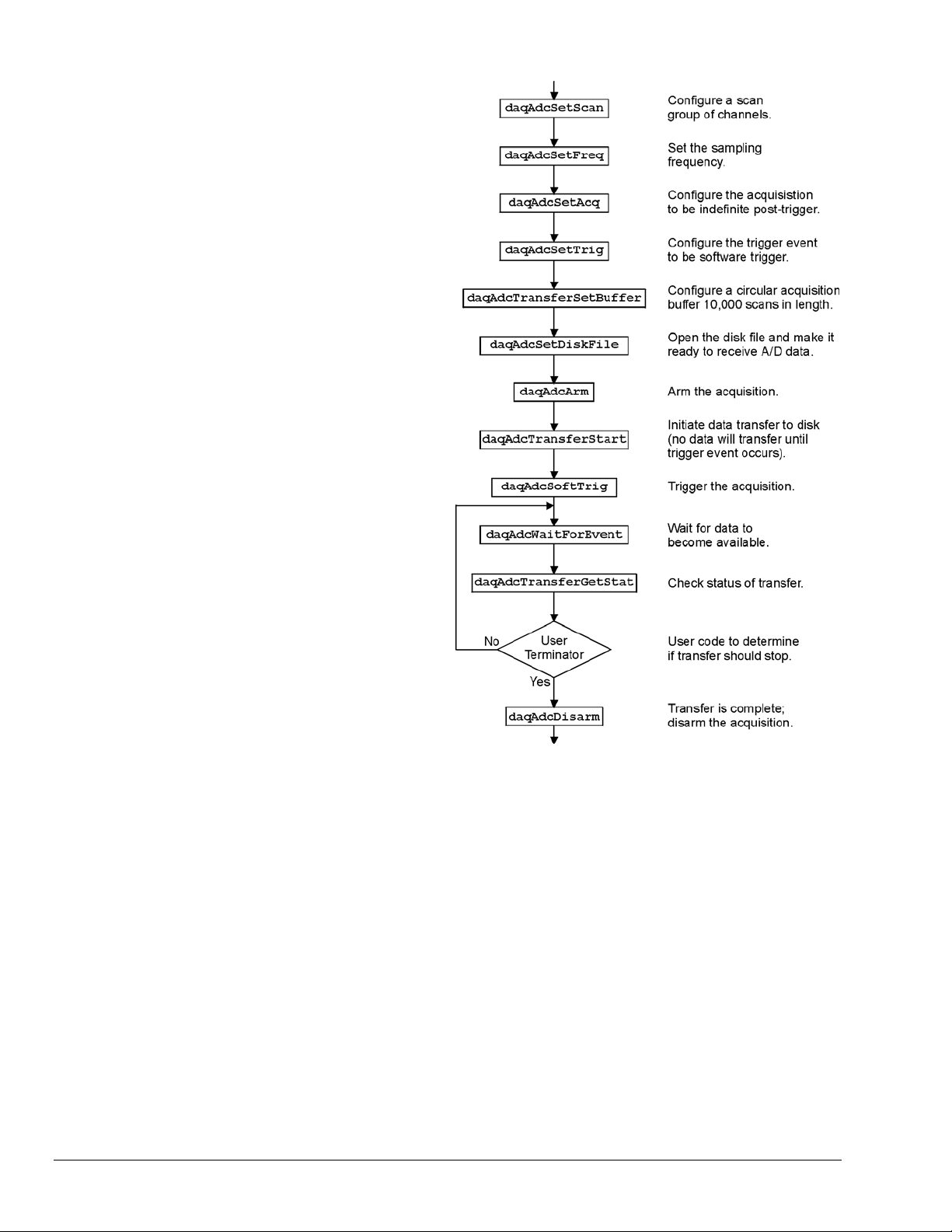
Indefinite Acquisition, Direct-To-Disk Using Circular Buffers
This program demonstrates the use of
circular buffers in cycle mode to collect
analog input data directly to disk. In cycle
mode, this data transfer can continue
indefinitely. When the transfer reaches the
end of the physical data array, it will reset
its array pointer back to the beginning of
the array and continue writing data to it.
Thus, the allocated buffer can be used
repeatedly like a FIFO buffer.
The API has built-in direct-to-disk
functionality. Therefore, very little needs
to be done by the application to configure
direct-to-disk operations.
First, the acquisition is configured by
setting up the channel scan group
configuration, the acquisition frequency,
the acquisition trigger and the acquisition
mode. Once configured, the transfer to
disk is set up and the acquisition is then
armed by calling the
daqAdcArm function.
At this point, the Daq device trigger is
armed and A/D acquisition to disk will
begin immediately upon trigger detection.
This example will retrieve an indefinite
amount of scans for channels 0 through 7,
triggered via software with a 3000 Hz
sampling frequency and unity gain.
Functions used include:
• VBdaqAdcSetScan&(handle&, startChan&, endChan&, gain&, flags&)
• VBdaqAdcSetFreq&(handle&,freq!)
• VBdaqAdcSetTrig&(handle&, triggerSource&, rising&, level%,
hysteresis%,channel&)
• VBdaqAdcSetAcq&(handle&,mode&,preTrigCount&,postTrigCount&)
• VBdaqAdcTransferSetBuffer&(handle&,buf%(), scanCount&, transferMask&)
• VBdaqAdcTransferStart&(handle&)
• VBdaqAdcTransferGetStat&(handle&,status&,retCount&)
• VBdaqAdcWaitForEvent&(handle&,daqEvent&)
• VBdaqAdcSetDiskFile&(handle&,filename$,openMode&,preWrite&)
This program will initialize the Daq device hardware, then take readings from the analog input channels in
the base unit (not the expansion cards) and store them to disk automatically. The following lines
demonstrate channel scan group configuration using the
daqAdcSetScan command.
Note: flags may be channel-specific.
2-14 API Programming, General Models 988594 Programmer’s Manual
Page 25

Dim handle&, ret&, channels&(8), gains&(8) flags&(8)
Dim buf%(80000), active&, count&
Dim bufsize& = 10000 ‘ In scans
' Define arrays of channels and gains : 0-7 , unity gain
For x& = 0 To 7
channels&(x&) = x&
gains&(x&) = DgainX1&
flags&(x&) = DafAnalog& + DafSingleEnded& + DafUnipolar&
Next x&
' Load scan sequence FIFO
ret& = VBdaqAdcSetScan&(handle&,channels&(), gains&(), flags&(), 8)
Next, set the internal sample rate to 3 kHz.
ret& = VBdaqAdcSetFreq&(handle&,3000!)
The acquisition mode needs to be configured to be fixed-length acquisition with no pre-trigger scan data
and 10 scans of post-trigger scan data. The mode is set to
DaamInfinitePost&, which will configure the
acquisition as having indefinite length and, as such, will be terminated by the application. In this mode, the
pre- and post-trigger count values are ignored.
ret& = VBdaqAdcSetAcq&(handle&,DaamInfinitePost&, 0, 0)
The acquisition begins upon detection of the trigger event. The trigger event is configured with
daqAdcSetTrig. The next line defines the trigger event to be the immediate trigger source which will
start the acquisition immediately. The variable
DatsSoftware& is a constant defined in DaqX.bas. Since
the trigger source is configured as immediate, the other trigger parameters are not needed.
ret& = VBdaqAdcSetTrig&(handle&,DatsSoftware&, 0, 0, 0, 0)
A buffer now is configured to hold the A/D data to be acquired. This buffer is necessary to hold incoming
A/D data while it is being prepared for disk I/O. Since this is to be an indefinite-length transfer to a
circular buffer, the buffer cycle mode should be turned on with
update mode is specified with
DatmUpdateBlock&. The buffer size is set to 10,000 scans. The buffer
DatmCycleOn&. For efficiency, block
size indicates only the size of the circular buffer, not the total number of scans to be taken.
ret& = VBdaqAdcTransferSetBuffer&(handle&,buf%(), bufsize&,
DatmUpDateBlock&+DatmCycleOn&)
Now the destination disk file is configured and opened. For this example, the disk file is a new file to be
created by the driver. After the following line has been executed, the specified file will be o pened and
ready to accept data.
ret& = VBdaqAdcSetDiskFile&(handle&,”c:dasqdata.bin”, DaomCreateFile&, 0)
With all acquisition parameters being configured and the acquisition transfer to disk configured, the
acquisition can now be armed. Once armed, the acquisition will begin immediately upon detection of the
trigger event. As in the case of the immediate trigger, the acquisition will begin immediately upon
execution of the daqAdcArm function.
ret& = VBdaqAdcArm&(handle&)
After setting up and arming the acquisition, data collection will begin upon satisfaction of the trigger event.
Since the trigger source is software, the trigger event will not take place until the application issues the
software trigger event. To prepare for the trigger event, the following line initiates an A/D transfer from
the Daq device to the defined user buffer and, subsequently, to the specified disk file. No data is
transferred at this point, however.
ret& = VBdaqAdcTransferStart&(handle&)
The transfer has been initiated, but no data will be transferred until the trigger event occurs. The following
line will signal the software trigger event to the driver; then A/D input data will be transferred to the
specified disk file as it is being collected.
ret& = VBdaqAdcSoftTrig&(handle&)
Programmer’s Manual 988594 API Programming, General Models 2-15
Page 26
Both the acquisition and the transfer are now currently active. The transfer to disk will continue
indefinitely until terminated by the application. The application can monitor the transfer process with the
following lines of code:
acqTermination& = 0
Do
‘ Wait here for new data to arrive
ret& = VBdaqWaitForEvent(handle&,DteAdcData&)
‘ New data has been transferred - Check status
ret& = VBdaqAdcTransferGetStat&(handle&,active&,retCount&)
‘ Code may be placed here which will process the buffered data or
‘ perform other application activities
‘
‘ At some point the application needs to determine the event on which
‘ the direct-to-disk acquisition is to be halted and set the
‘ acqTermination flag.
Loop While acqTermination& = 0
At this point the application is ready to terminate the acquisition to disk. The following line will terminate
the acquisition to disk and will close the disk file.
ret& = VBdaqAdcDisarm&(handle&)
The acquisition as well as the data transfer has been stopped. We should check status one more time to get
the total number of scans actually transferred to disk.
ret& = VBdaqAdcTransferGetStat(handle&,active&,retCount&)
The specified disk file is now available. The
retCount& parameter will indicate the total number of scans
transferred to disk.
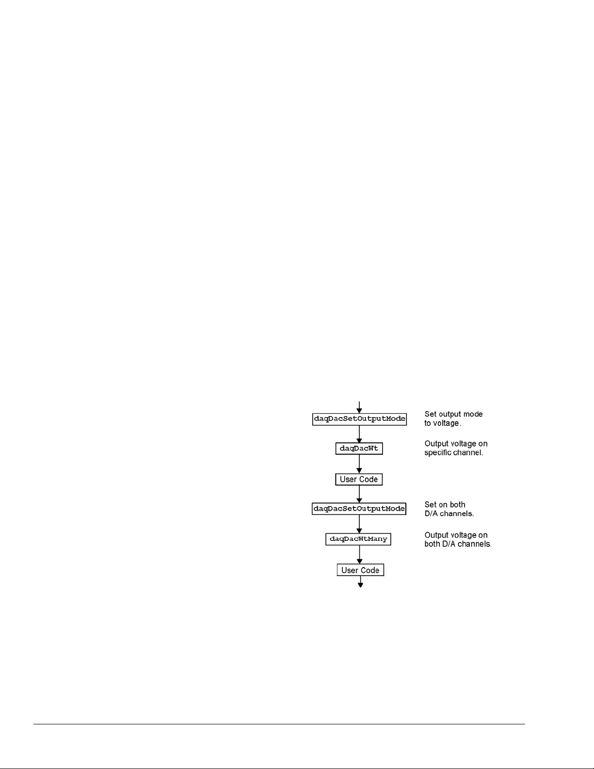
Analog Output
The program DACEX1.BAS shows how to
output analog voltages on analog output
channels 0 and 1. These commands only
have to be issued one time unless a related
parameter is explicity changed. The output
voltages will be sustained. This example
demonstrates the use of the two digital-toanalog converters (values used assume
bipolar mode). Functions used include:
• VBdaqDacSetOutputMode&(ha
ndle&, DddtLocal&, 0,
DdomVoltage&)
• VBdaqDacWt&(handle&,
deviceType&, chan&,
dataVal%)
• VBdaqDacWtMany&(handle,
deviceTypes&(),chans&(),
dataVals&())
2-16 API Programming, General Models 988594 Programmer’s Manual
Page 27

Assuming the voltage reference is connected to the internal default of 5 V, the next function will set
channel 0 to an output voltage of 5 V. The values are set for a digital-to-analog converter with 16 bit
resolution; 65535 represents full-scale. Channel 1 is equal to 0.
ret& = VBdaqDacSetOutputMode&(handle&, DddtLocal&, 0, DdomVoltage&)
ret& = VBdaqDacWt&(handle&, DddtLocal, 0, 65535)
The daqDacWtMany writes to both analog outputs simultaneously. The following lines sets channel 0 to 5
V and channel 1 to 2.5 V. At full-scale, a digital value of 65535 corresponds to 5 V; a digital value of
49152 corresponds to ½ of 5 V.
Dim deviceTypes&(1)
Dim chans&(1)
Dim dataVals%(1)
The VBdaqSetOutputMode puts the channel in a voltage mode.
ret& = VBdaqSetOutputMode&(handle&, DddtLocal&, 0, DdomVoltage&)
ret& = VBdaqSetOutputMode&(handle&, DddtLocal&, 1, DdomVoltage&)
deviceTypes&(0) = DddtLocal&
deviceTypes&(1) = DddtLocal&
chans&(0) = 0
chans&(1) = 1
dataVals&(0) = 65535
dataVals&(1) = 49152
ret& = VBdaqDacWtMany&(handle&, deviceTypes&(), chans&(), dataVals&(),2)
The following sets the outputs to 0 V.
Dim deviceTypes&(1)
Dim chans&(1)
Dim dataVals%(1)
deviceTypes&(0) = DddtLocal&
deviceTypes&(1) = DddtLocal&
chans&(0) = 0
chans&(1) = 1
dataVals&(0) = 32768
dataVals&(1) = 32768
ret& = VBdaqDacSetOutputMode&(handle&, DddtLocal&, 0, DdomVoltage&)
ret& = VBdaqDacSetOutputMode&(handle&, DddtLocal&, 1, DdomVoltage&)
ret& = VBdaqDacWtMany&(handle&, deviceTypes&(), chans&(), dataVals&(),2)
Programmer’s Manual 988594 API Programming, General Models 2-17
Page 28
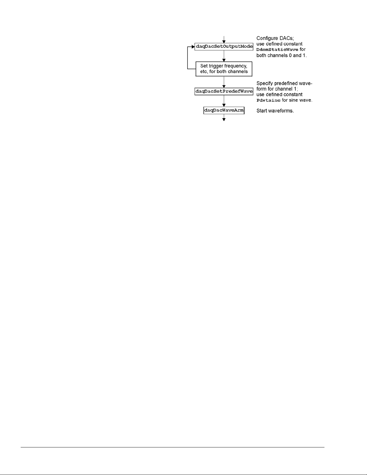
Generating DAC FIFO Waveforms
This program demonstrates the use of the
DAC FIFO to generate waveforms. The
DAC is configured for output on both
channels, and the user waveform is
constructed. Output begins after the
waveform is assigned to a channel. At this
point, the program continues while the
waveforms are generated.
The following example shows how to
generate a pre-defined waveform using
these functions:
• VBdaqDacWaveSetTrig&(handle&, deviceType&, chan&, triggerSource&,
rising%)
• VBdaqDacWaveSetClockSource&(handle&, deviceType&, chan&, clockSource&)
• VBdaqDacWaveSetFreq&(handle&, deviceType&, chan&, freq!)
• VBdaqDacWaveSetMode&(handle&, deviceType&, chan&, mode&, updateCount&)
• VBdaqDacWaveSetBuffer&(handle&, deviceType&, chan&, buf%(), scanCount&,
transferMask&)
• VBdaqDacWaveSetPredefWave&(handle&, deviceType&, chan&, waveType&,
amplitude&, offset&, dutyCycle&, phaseShift&)
• VBdaqDacWaveArm&(ByVal handle&, ByVal deviceType&)
When using the pre-defined waveform generation, program the waveform parameters common to both
channels. The double star (**) indicates the value must be the same on both channels of a DaqBoard.
For chan = 0 To 1 Step 1
' set the output mode to static waveform
ret& = VBdaqDacSetOutputMode&(handle&, DddtLocal&, chan&, DdomStaticWave&)
' The trigger source must be set to immediate for static waveform.**
err& = VBdaqDacWaveSetTrig&(handle&, DddtLocal&, chan&, DdtsImmediate&, 1)
' set the internal dac clock
ret& = VBdaqDacWaveSetClockSource&(handle&, DddtLocal&, chan&,
DdcsDacClock&)
' the frequency of the internal clock. **
ret& = VBdaqDacWaveSetFreq&(handle&, DddtLocal&, chan&, 10!)
' must be infinite for static mode
ret& = VBdaqDacWaveSetMode&(handle&, DddtLocal&, chan&, DdwmInfinite&, 0)
Next chan
' buffer cylce on, retransmit mode. **
' update count is the buffer length. **
ret& = VBdaqDacWaveSetBuffer&(handle&, DddtLocal&, chan&, buf0%(),
updateCount&, DdtmCycleOn&)
' set the buffer for channel 1
ret& = VBdaqDacWaveSetBuffer&(handle&, DddtLocal&, chan&, buf1%(),
updateCount&, DdtmCycleOn&)
' program the waveform parameters specific to dac channel 0
ret& = VBdaqDacWaveSetPredefWave&(handle&, DddtLocal&, 0, DdwtTriangle&,
32768, 32768, 90, 0)
' program the waveform parameters specific to dac channel 1
ret& = VBdaqDacWaveSetPredefWave&(handle&, DddtLocal&, 1, DdwtSquare&,
32768, 32768, 40, 0)
' buffer must be configured before the arm command is called. All channels
' will be armed.
ret& = VBdaqDacWaveArm(handle&, DddtLocal&)
2-18 API Programming, General Models 988594 Programmer’s Manual
Page 29
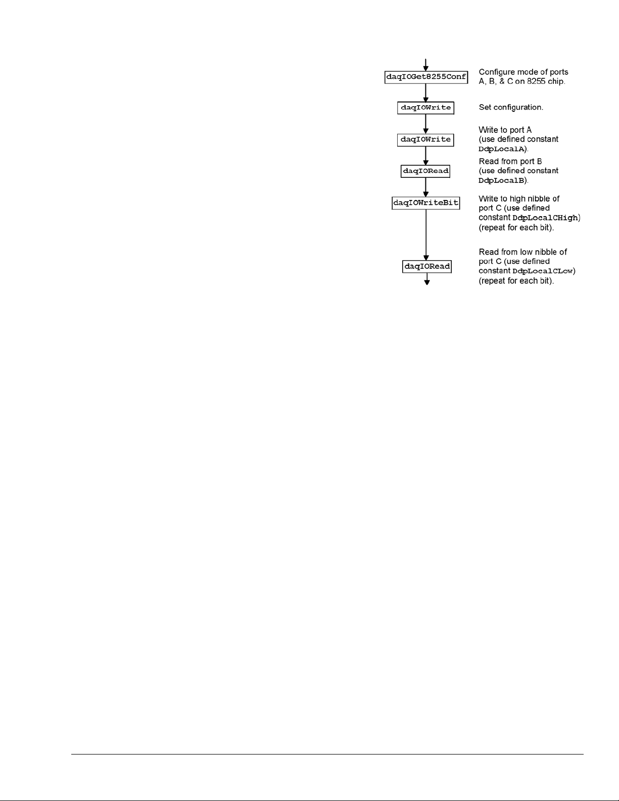
Digital I/O on P2
This program demonstrates the functions
controlling digital I/O on the P2 connector of the
device. First, the 3 digital ports on the 8255 are
configured as input, output, or both in the case of
port C; then, appropriate I/O commands are
issued. Functions used include:
• VBdaqIOReadBit&(handle&,
• VBdaqIORead&(handle&,
• VBdaqIOWriteBit&(handle&,
• VBdaqIOWrite&(handle&,
• VBdaqIOGet8255Conf&(handle&,
The function daqIOGet8255Conf returns the appropriate configuration value to use in daqIOWrite. As
shown above, the handle of the opened Daq device is the first parameter passed. The second, third, fourth,
and fifth parameters respectively indicate: the 8255 port A value, the port B value, the high-nibble value of
port C, and the low-nibble value of port C. The values for the parameters passed in the call shown above
will return the configuration value (port A = OUTPUT, port B = INPUT, p ort C / high nibble = output, port
C / low nibble = INPUT) in the config& parameter, which matches the current configuration of the 8255.
devType&, devPort&,
whichDevice&, whichExpPort&,
bitNum&, bitValue&)
devType&, devPort&,
whichDevice&, whichExpPort&,
value&)
devType&, devPort&,
whichDevice&, whichExpPort&,
bitNum&, bitValue&)
devType&, devPort&,
whichDevice&, whichExpPort&,
value&)
portA&, portB&, portCHigh&,
portCLow&, config&)
Dim config&, byteVal&, bitVal&, x%
Dim buf(10) As Byte, active&, retCount&
handle& = VBdaqOpen&(“DaqBook0”)
ret& = VBdaqSetErrorHandler&(handle&, 100)
On Error GoTo ErrorHandlerDIG1
ret& = VBdaqIOGet8255Conf&(handle&, 0, 1, 0, 1, config&)
The daqIOWrite function writes the obtained configuration value to the selected port.
ret& = VBdaqIOWrite&(handle&, DiodtLocal8255&, Diodp8255IR&, 0, 0,_ config&)
Write hex 55 to port A on the Daq device’s base unit.
ret& = VBdaqIOWrite&(handle&, DiodtLocal8255&, Diodp8255A&, 0, 0,_ &H55)
Read port B and put the value into the variable b yteVal%.
ret& = VBdaqIORead&(handle&, DiodtLocal8255&, Diodp8255B&, 0, 0,_ byteVal&)
Print "The value on digital port B : &H"; Hex$(byteVal&): Print
The following lines write to the high nibble of port C.
ret& = VBdaqIOWriteBit&(handle&,DiodtLocal8255&,Diodp8255CHigh&,0,_ 0,0,1)
ret& = VBdaqIOWriteBit&(handle&,DiodtLocal8255&,Diodp8255CHigh&,0,_ 0,1, 0)
ret& = VBdaqIOWriteBit&(handle&,DiodtLocal8255&,Diodp8255CHigh&,0,_ 0, 2, 1)
ret& = VBdaqIOWriteBit&(handle&,DiodtLocal8255&,Diodp8255CHigh&,0,_ 0, 3, 0)
Print "The high nibble of digital port C set to : 0101 (&H5)": Print
The next lines read the low nibble of port C on the base unit.
Programmer’s Manual 988594 API Programming, General Models 2-19
Page 30
For x% = 0 To 3
ret& = VBdaqIOReadBit&(handle&, DiodtLocal8255&,_ Diodp8255CLow&,
0, 0, x%, bitVal&)
Print "The value on bit "; x%; " of digital port C : &H";_ Hex$(bitVal&)
Next x%
Using DBK Card Calibration Files
Software calibration functions are designed
to adjust Daq device readings to
compensate for gain and offset errors.
Calibration constants are calculated at the
factory by measuring the gain and offset
errors of a card at each programmable gain
setting. These constants are stored in a
calibration text file that can be read by a
program at runtime. This allows new
boards to be configured for calibration by
updating this calibration file rather than
recompiling the program. Calibration
constants and instructions are shipped with
the related DBK boards. Programs like
DaqView support this calibration and use
the same constants.
The calibration operation removes static
gain and offset errors that are inherent in
the hardware. The calibration constants
are measured at the factory and do not
change during the execution of a program.
These constants are different for each card
and programmable-gain setting; they may
even be different for each channel,
depending on the design of the expansion
card.
Note: DBK19 is shipped with calibration constants. Other cards use on-board potentiometers to perform hardware
calibration.
The calibration process has 3 steps:
• Initialization consists of reading the calibration file.
• Setup describes the characteristics of the data to be calibrated.
• Conversion does the actual calibration of the data.
[MAIN]
32760,32769
32801,32750
32740,32777
32810,32768
[EXP3]
32780,32779
32800,32756
32768,32780
32750,32742
[EXP5]
32752,32764
32783,32757
32749,32767
32777,32730
Function prototypes, return error codes, and parameter definitions are located in the
DAQX.H header file for C (or similar files for other languages).
Cards that support the calibration functions are shipped with a diskette containing a
calibration constants file. The name of the file will be the serial number of the card
shipped with it. This file holds the calibration constants for each programmablegain setting of that card. These constants should be copied to a calibration text file
(DAQBOOK.CAL) located in the same directory as the program performing the
calibration.
To set up the calibration file, perform the following steps:
2-20 API Programming, General Models 988594 Programmer’s Manual
Page 31

1. Locate the diskette containing the calibration constants file.
2. Configure the card according to instructions found in the DBK documentation (included on your CD,
or in hardcopy).
3. Edit the calibration file, DAQBOOK.CAL, using a text editor.
4. Add the card number information within brackets, as listed in the calibration file.
5. Add the calibration constants immediately after the card number. (These should be entered in the
order given in the calibration file.)
6. Repeat steps 4 and 5 for each card.
7. Verify that no two cards are configured with the same card/channel number.
The table shows an example of a calibration file for configuring the main Daq device unit and two DBK19
cards connected to Daq device expansion channels 3 and 5.
The initialization function for reading in the calibration constants from the calibration text file is
daqReadCalFile. The C language version of daqReadCalFile is similar to other languages and works as
follows:
The filename with optional path information of the calibration file. If calfile is NULL or empty (“”), the
default calibration file DAQBOOK.CAL will be read. This function is usually called once at the beginning
of a program and will read all the calibration constants from the specified file. If calibration constants for a
specific channel number and gain setting are not contained in the file, ideal calibration constants will be
used (essentially not calibrating that channel). If an error occurs while trying to open the calibration file,
ideal calibration constants will be used for all channels and a non-zero error code will be returned by the
daqReadCalFile function.
Once the calibration constants have been read from the cal file, they can be used by the
daqCalConvert functions. The daqCalSetup function will configure the order and type of data to be
daqCalSetup and
calibrated. This function requires data to be from consecutive channels configured for the same gain,
polarity, and channel type. The calibration can be configured to use only the gain calibration constant and
not the offset constant. This allows the offset to be removed at runtime using the zero compensation
functions described later in this section.
In this example, several Daq device channels will be read and calibrated. This example assumes the
calibration file has been created according to the initializing calibration constants section of this chapter.
Expansion cards can perform the same type of calibration if the calibration constants are available for the
card and a specified channel number. First list the configuration:
Channel Channel Type
0 Voltage1 @ X1 gain
1 Voltage2 @ X2 gain
2 Voltage3 @ X2 gain
3 Voltage4 @ X2 gain
Now specify the scan (the sequence of channel numbers and gains that are to be gathered as one burst of
readings). In this example, all the channels at each gain will be read together (in consecutive order) to
make the calibration easier.
Scan
Position
0 Voltage1 @ X1 gain 0 DgainX1
1 Voltage2 @ X2 gain 1 DgainX2
2 Voltage3 @ X2 gain 2 DgainX2
3 Voltage4 @ X2 gain 3 DgainX2
Channel Type Channel Gain
Code
Programmer’s Manual 988594 API Programming, General Models 2-21
Page 32

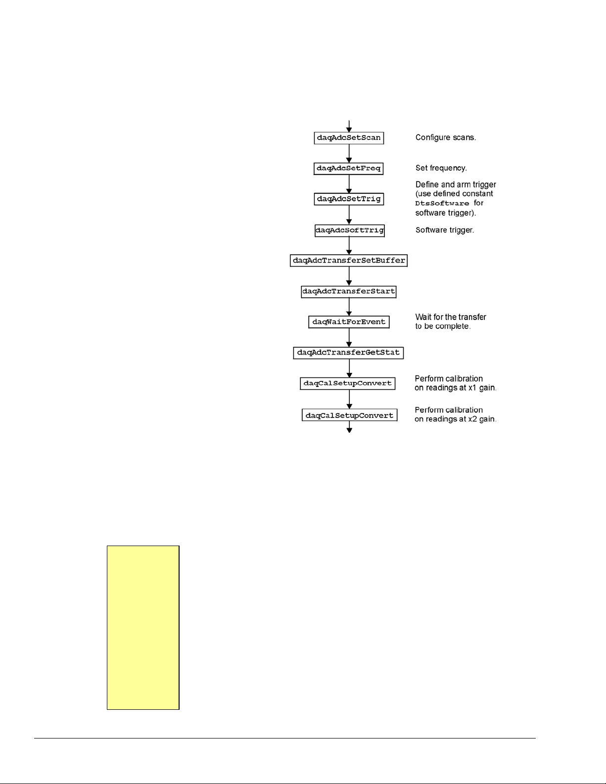
Now configure the Daq device with this information, and read 5 scans of data:
Dim chans&(4), gains&(4), buf%(20)
handle& = VBdaqOpen&(“DaqBook0”)
' Set array of channels and gains
chans&(0) = 0
gains&(0) = DgainX1&
chans&(1) = 1
gains&(1) = DgainX2&
chans&(2) = 2
gains&(2) = DgainX2&
chans&(3) = 3
gains&(3) = DgainX2&
' Load scan sequence FIFO :
ret& = VBdaqAdcSetScan&(handle&, chans&(), gains&(), 4)
' Set Clock
ret& = VBdaqAdcFreq&(handle&, 10)
' Define and arm trigger :
ret& = VBdaqAdcSetTrig&(handle&, DtsSoftware&, 0, 0, 0, 0)
' Trigger
ret& = VBdaqAdcSoftTrig&(handle&)
' Read the data
‘ 5 indicates the number of scans
‘ single mode for scans less than 500
ret& = VBdaqAdcTransferSetBuffer&(handle&, buf%(), 5, DatmCycleOff& +
DatmSingleMode&)
ret& = VBdaqAdcTransferStart&(handle&)
‘specifies to wait for the transfer to be complete
ret& = VBdaqWaitForEvent&(handle&, DteAdcDone&)
ret& = VBdaqAdcTransferGetStat&(handle&, active&, retCount&)
' Print the first scan of unconverted data
PRINT "Before Calibration:"
PRINT "Channel 0 at x1 gain: "; buf%(0)
PRINT "Channel 1 at x2 gain: "; buf%(1)
PRINT "Channel 2 at x2 gain: "; buf%(2)
PRINT "Channel 3 at x2 gain: "; buf%(3)
'Perform zero compensation on readings sampled at x1 gain
ret& = VBdaqCalSetupConvert&(handle&, 4, 0, 1, 0, DgainX1&, 0, 1, 0, buf%(),
5)
'Perform zero compensation on readings sampled at x2 gain
ret& = VBdaqCalSetupConvert&(handle&, 4, 1, 3, 0, DgainX2&, 1, 1, 0, buf%(),
5)
' Print the first scan of converted data
PRINT "After Calibration:"
PRINT "Channel 0 at x1 gain: "; buf%(0)
PRINT "Channel 1 at x2 gain: "; buf%(1)
PRINT "Channel 2 at x2 gain: "; buf%(2)
PRINT "Channel 3 at x2 gain: "; buf%(3)
2-22 API Programming, General Models 988594 Programmer’s Manual
Page 33

Zero Compensation
Zero compensation removes offset errors
while a program is running. This is useful
in systems where the offset of a channel
may change due to temperature changes,
long-term drift, or hardware calibration
changes. Reading a shorted channel on the
same card at the same gain as the desired
channel removes the offset at run-time.
Note: Zero compensation is not available
for all expansion cards. The DBK19 has
channel 1 permanently shorted for zero
compensation; other cards require a
channel to be shorted manually.
The zero-compensation functions require a
shorted channel and a number of other
channels to be sampled from the same card
at the same gain as the shorted channel.
These functions will work with cards
(such as the DBK12, DBK13, and DBK19)
that have one analog path from the input to
the A/D converter. Other cards do not
support the zero compensation functions
because they have offset errors unique to
each channel. The DBK19 is designed
with channel 1 already shorted for
performing zero compensation.
The
daqZeroSetup function configures the location of the shorted channel and the channels to be zeroed
within a scan, the size of the scan, and the number of readings to zero compensate. (This function does not
do the conversion.) A non-zero return value indicates an invalid parameter error.
In this example, several Daq device channels will be read using various gains and zero-compensated to
remove any offset errors. This example assumes that channel 0 of the Daq device has been manually
shorted. Expansion cards could perform the same type of zero compensation as this example by shorting a
channel on the expansion card and specifying card channel numbers. First list the configuration:
Channel Channel Type
0 Shorted Channel
1 Voltage1 @ X1 gain
2 Voltage2 @ X2 gain
3 Voltage3 @ X2 gain
4 Voltage4 @ X2 gain
Now specify the scan, the sequence of channel numbers, and gains that are to be gathered as one burst of
readings. In this example, we will first read the shorted channel at each gain that we plan on using, in this
case ×1 and ×2. All the channels at each gain will be read together to make the actual zero compensation
easier.
Scan
Position
0 Shorted Channel @ X1 0 DgainX1
1 Shorted Channel @ X2 0 DgainX2
2 Voltage1 @ X1 gain 1 DgainX1
3 Voltage2 @ X2 gain 2 DgainX2
4 Voltage3 @ X2 gain 3 DgainX2
5 Voltage4 @ X2 gain 4 DgainX2
Channel Type Channel Gain
Code
Programmer’s Manual 988594 API Programming, General Models 2-23
Page 34

Public Sub ZeroComp()
' Performs zero compensation on ADCs readings
Const ScanLength& = 6 'Total channels per scan
Const ScanCount& = 5 'Number of scans to acquire
Dim chan&(ScanLength), gain&(ScanLength)
Dim flag&(ScanLength), buf%(ScanLength * ScanCount)
Dim ret&, daqHandle&
daqHandle& = VBdaqOpen&("daqbook0")
' Channel zero must be shorted to ground
' Use DafClearLSNibble flag to clear 4 least significant
' bits when using 12-bit A/D converters
chan&(0) = 0: gain&(0) = DgainX1&: flag&(0) = DafBipolar& +
DafClearLSNibble&
chan&(1) = 0: gain&(1) = DgainX2&: flag&(1) = DafBipolar& +
DafClearLSNibble&
chan&(2) = 1: gain&(2) = DgainX1&: flag&(2) = DafBipolar& +
DafClearLSNibble&
chan&(3) = 2: gain&(3) = DgainX2&: flag&(3) = DafBipolar& +
DafClearLSNibble&
chan&(4) = 3: gain&(4) = DgainX2&: flag&(4) = DafBipolar& +
DafClearLSNibble&
chan&(5) = 4: gain&(5) = DgainX2&: flag&(5) = DafBipolar& +
DafClearLSNibble&
ret& = VBdaqAdcSetScan&(daqHandle&, chan&(), gain&(), flag&(), ScanLength)
ret& = VBdaqAdcSetTrig&(daqHandle&, DatsImmediate&, 1, 0, 0, 0)
ret& = VBdaqAdcSetAcq&(daqHandle&, DaamNShot&, 0, ScanCount)
ret& = VBdaqAdcSetClockSource&(daqHandle&, DacsAdcClock&)
ret& = VBdaqAdcSetFreq&(daqHandle&, 100!)ret& =
VBdaqAdcTransferSetBuffer&(daqHandle&, buf%(), ScanCount, DatmCycleOff& +
DatmUpdateSingle&)
ret& = VBdaqAdcTransferStart&(daqHandle&)
ret& = VBdaqAdcArm&(daqHandle&)
ret& = VBdaqWaitForEvent&(daqHandle&, DteAdcDone&)
' Print the first scan of unconverted data
Print "Channel zero shorted to ground"
Print "Channel 0 at X1 gain: "; IntToUint(buf%(0))
Print "Channel 0 at X2 gain: "; IntToUint(buf%(1))
Print
Print "Before zero compensation"
Print "Channel 1 at X1 gain: "; IntToUint(buf%(2))
Print "Channel 2 at X2 gain: "; IntToUint(buf%(3))
Print "Channel 3 at X2 gain: "; IntToUint(buf%(4))
Print "Channel 4 at X2 gain: "; IntToUint(buf%(5))
Print
' Perform zero compensation on readings sampled at x1 gain.
' 1 reading at position 2. Zero reading at position 0.
ret& = VBdaqZeroSetupConvert&(ScanLength, 0, 2, 1, buf%(), ScanCount)
' Perform zero compensation on readings sampled at x2 gain.
' 3 readings at position 3. Zero reading at position 1.
ret& = VBdaqZeroSetupConvert&(ScanLength, 1, 3, 3, buf%(), ScanCount)
' Print the first scan of converted data
Print "After zero compensation"
Print "Channel 1 at X1 gain: "; IntToUint(buf%(2))
Print "Channel 2 at X2 gain: "; IntToUint(buf%(3))
Print "Channel 3 at X2 gain: "; IntToUint(buf%(4))
Print "Channel 4 at X2 gain: "; IntToUint(buf%(5))
Print
' Close the device
ret& = VBdaqClose&(daqHandle&)
End Sub
Function IntToUint(intval As Integer) As Long
' Converts 16-bit signed integer to unsigned long integer
If 0 <= intval Then
2-24 API Programming, General Models 988594 Programmer’s Manual
Page 35

IntToUint = intval
Else
IntToUint = 65535 + CLng(intval) + 1
End If
End Function
Linear Conversion
Several DBKs use conversions from A/D
readings to corresponding values that are a
linear (straight-line) relationship. (Nonlinear relationships for RTDs and
thermocouples require special conversion
functions—refer to the Thermocouple and
RTD Linearization section later in this
chapter.) The linear conversion functions
are built into the API.
Six parameters are used to specify a linear
relationship: the A/D input range
(minimum and maximum values), and the
transducer input signal level and output
voltage at two points in the range.
Three functions are used to perform linear
conversions: daqCvtLinearSetup,
daqCvtLinearConvert, and
daqCvtLinearSetupConvert. These
functions are defined in the following
pages. After their definitions, parameter
examples and a program example show
how they work.
DBK7, programmed for 50 to 60 Hz:
Measurement Signal Voltage
1 50 Hz -5 V
2 60 Hz +5 V
The DBK7 output range is from -5 V to +5 V, and the Daq device must be configured for bipolar operation
at a gain of ×1 for the DBK7 channels. Thus, the input range -5 V to +5 V corresponds to the ADmin and
ADmax settings. When a DBK7 programmed for a 50 to 60 Hz range measures a 50 Hz input signal, it
outputs -5 V. With a 60 Hz input signal, it outputs +5 V. Thus, signal1 is 50, voltage1 is -5, signal2 is 60,
and voltage2 is 5.
Pressure-transducer:
Measurement Signal Voltage
1 0 psi 1 mV
2 1000 psi 4 mV
Assume that a pressure transducer outputs 1 to 4 mV to represent 0 to 1000 psi, and that a DBK13 with a
gain of ×1000 is used with a Daq device in bipolar mode to measure the signal. In bipolar mode, at a gain
of 1000, the analog signal input range is -5 to 5 mV and the output range from the DBK13 is -5 to 5 Volts.
Thus, ADmin is -5.000, and ADmax is 5.000. A pressure of 0 psi generates an output of 1 mV, and 1000
psi generates 4 mV. Thus signal1 is 0, voltage1 is 1.000, signal2 is 1000 and voltage2 is 4.000.
This program uses the linear conversion functions to convert voltage readings from a DBK7 frequency-tovoltage card and a DBK13 voltage input card with a pressure transducer to actual frequencies (Hz) and
pressures (psi).
Programmer’s Manual 988594 API Programming, General Models 2-25
Page 36

End Sub
Public Sub LinearConvert()
Dim buffer1%(80), buffer2%(80), flags&(3), hz!(20), psi!(10)
Dim ret&, handle&, chan&, x%
' Initialize DaqBook
handle& = VBdaqOpen&("DaqBook0")
'Set Channel 16 to be a DBK7. This will configure and auto'calibrate all channels on the DBK7 which includes channels
'16,17,18, and 19. This step not required for a DBK13
ret& = VBdaqAdcExpSetBank(handle&, 16, DbankDbk7&)
'Set channel option common to all DBK7 channels.
'This step not required by a DBK13.
For chan& = 16 To 19
ret& = VBdaqAdcExpSetChanOption(handle&, chan&, DcotDbk7Slope&, 1)
ret& = VBdaqAdcExpSetChanOption(handle&, chan&, DcotDbk7DebounceTime&,
DcovDbk7DebounceNone&)
ret& = VBdaqAdcExpSetChanOption(handle&, chan&, DcotDbk7MinFreq&, 50!)
ret& = VBdaqAdcExpSetChanOption(handle&, chan&, DcotDbk7MaxFreq&, 60!)
Next chan&
'Channel configuration:
'DaqBook Channels 16, 17: DBK7 channels 0,1
'DaqBook Channel 32: DBK13 channel 0
'Configure the pacer clock, arm the trigger, and acquire 10
'scans. The gain setting of Dbk7X1 (X1 gain) will be applied
'to all channels. The acquisition frequency is set to 100 Hz.
'All channels are unsigned - bipolar.
ret& = VBdaqAdcRdScanN&(handle&, 16, 17, buffer1%(), 10, DatsAdcClock&, 0,
0, 100!, Dbk7X1&, DafUnsigned& + DafBipolar&)
'Now do the same for the DBK13 channel, using gain Dbk13X1000
ret& = VBdaqAdcRdN(handle, 32, buffer2%(), 10, DatsAdcClock&, 0, 0, 100!,
Dbk13X1000&, DafUnsigned& + DafUnipolar&)
'Convert channels 16 and 17 to Hertz where -5 volts corresponds
'to 50 Hz and 5 volts corresponds to 60 Hz.
ret& = VBdaqCvtLinearSetupConvert(2, 0, 2, 50!, -5!, 60!, 5!, 1, buffer1%(),
10, hz!(), 20)
'Convert channel 32 to PSI where 1mV corresponds to 0 PSI and
'4 mV corresponds to 1000 PSI. DBK13 channel 0 has 1000x gain,
'so 1mV at Dbk13 input gives 1V output at DaqBook input.
ret& = VBdaqCvtLinearSetupConvert(1, 0, 1, 0!, 1!, 1000!, 4!, 1, buffer2%(),
10, psi!(), 10)
'Print results
Print "Results:"
For x = 0 To 9
Print Format(hz!(x * 2), "#0.00 Hz "); Format(hz!(x * 2 + 1), "#0.00 Hz
"); Format(psi(x), "0000.0 psi")
Next x
ret& = VBdaqClose(handle&)
2-26 API Programming, General Models 988594 Programmer’s Manual
Page 37

Using Multiple Devices 3
Overview…… 3-1
Asynchronous Operation ……3-1
Synchronous Operation ……3-1
Asynchronous Operation of Multiple Devices …… 3-1
Synchronous Operation of Multiple Devices ……3-3
Internal Clock Method…… 3-4
Master Clock Method…… 3-5
External Clock Method……3-7
Overview
This chapter applies to all devices that can be used with the DaqX API. The purpose of this
chapter is to show how devices can be used concurrently in either a synchronous or
asynchronous fashion. Devices that have the ability to trigger from an external source or be
clocked by an external source have the ability to be used in a synchronized system.
Asynchronous Operation
Asynchronous operation of devices is defined as the inability to synchronize the input of data
between separate main unit devices. Data acquired with the devices is independent and the
time-skew between devices is non-deterministic.
In the following sections, both synchronous and asynchronous operation will be covered.
However, since synchronous operation requires more care in configuration most of the
remaining material in the chapter will cover synchronous operation of multiple devices.
For either synchronous or asynchronous operation modes device configuration and data
handling is very similar to the single device scenario. The DaqX API is a handle based API.
This means that each device session has a handle assigned to it when it is opened. This
device handle is then used to configure and acquire data from a device by referencing the
device handle when calling the appropriate DaqX API functions.
Synchronous Operation
Synchronous operation of devices is defined as having the ability to synchronize the input of
data between separate main unit devices. Data between devices is not time-skewed or the
time-skew between devices is deterministic.
Asynchronous Operation of Multiple Devices
All DaqX compatible devices may be run concurrently in an asynchronous manner. When
using the devices concurrently in an asynchronous manner the programming and data
collection techniques are very similar to the single device Here, the triggering events, stop
events and clocking of the input can be different between the devices.
As mentioned above, the DaqX API is a handle-based API. A handle-based API is an API which
assigns a unique handle to each device in use. As in the single device scenario, each device
needs to be opened using the daqOpen function. Each device should be opened using the
alias name given to the device in the Daq Configuration Utility located in the Control Panel of
WindowsNT/2000/XP operating system. As each device is opened a new, unique handle for
each device is generated and returned by the daqOpen function. The handle is a unique
identifier for each device and should be used when referencing DaqX functions for the device.
Using this model, each device needs to be uniquely configured using the appropriate handle
for the device. The acquisition of the data for each device also is managed independently for
each device. The diagram below shows how the application should operate with two devices
(designated as Device0 and Device1).
Programmer’s Manual 908494 Using Multiple Devices 3-1
Page 38

Using this model, each device needs to be opened and a device handle assigned. Here the
Controlling Process would open each device session according to the device inventory list (this
can be interrogated by inspecting the device inventory in the Daq Configuration utility located
in the Control Panel of the operating system). The Control Process would then pass each
device handle to the appropriate Device Process so that each device process can configure
the device and acquire data from the device.
Note: While the above diagram does indicate the division of responsibilities within the
application, the application may be organized in any fashion desirabl e. The individual
processes need not be separate tasks or threads in order for the multi-device model to
work well.
For discussion purposes, the responsibilities of the Controlling Process are as follows:
1. For each device, open the device session and retrieve the device handle (see daqOpen).
2. Pass each device handle to the appropriate Device Process so that the Device Process can
configure the acquisition for its device.
3. Process any data returned from each Device Process and update any outputs required.
4. Optionally, write the input data for each device to disk.
Each device process is responsible for performing the following steps in order:
1. Configure the channel scan group for the device including expansion channels (see
daqAdcSetScan for channel scan group configuration details).
2. Configure the acquisition clocking or rate to be used (see daqAdcSetRate and
daqAdcSetClockSource for details on scan rate clocking configurations).
3. Configure the acquisition mode to set pre-trigger, post-trigger and update mode ( see
daqAdcSetAcq for details on configuring acquisition mode parameters).
4. Configure the means by which the acquisition should start and terminate by configuring
the Trigger and Stop Events. (see daqSetTriggerEvent for more details on configuring
the Trigger and Stop Events).
5. Configure the buffer model to be used for the device. (see daqAdcTransferSetBuffer for
more details on configuration of the buffer model.
6. Initiate a transfer from the device (see daqAdcTransferStart) and arm the device to
detect the trigger event (see daqAdcArm ).
7. Monitor the status of the input data transfer and the acquisition (see
daqAdcTransferGetStat) and optionally pass data back to the Controlling Process.
Since this section deals with asynchronous operation, each device may be independently
programmed with respect to steps 1-7. When the devices are independently programmed
each device may take on separate acquisition settings such as Trigger/Stop Events, Pre/PostTrigger modes and buffer model settings. Independent device operation also implies that the
data acquired from the different devices cannot be temporally correlated. As such, data from
each device should be handled separately in either separate data buffers in memory or
separate disk files. Sections to follow illustrate using multiple devices in a synchronized
manner.
3-2 Using Multiple Devices 908494 Programmer’s Manual
Page 39

Synchronous Operation of Multiple Devices
The following sections describe methods for synchronizing input data with multiple DaqX compatible
devices. Three synchronization methods will be discussed:
o Internal Clock Method
o Master Clock Method
o External Clock Method
The synchronization method available depends upon the device, i.e., its ability to be externally triggered
or externally clocked. The following table shows the capabilities of each device as well as the physical
location of the external trigger and pacer input/output clocks.
Device External TTL Trigger External Acquisition
WaveBook/512 Yes (pin 13 on DB25F) No NA No
WaveBook/516 Yes (pin 13 on DB25F) Yes (pin 20 on DB25F) 1us (1MHz) No
DaqBooks Yes (P1; pin 25) No NA No
Daq PC-Card Yes (P1; pin 25) No NA No
DaqBoard(ISA) Yes (P1; pin 25) No NA No
TempBook Yes No NA No
DaqBoard/500 Series Yes (pin 6 on SCSI ;
DaqBoard/1000 Series Yes (pin 6 on SCSI ;
DaqBoard/2000 Series1
DaqBoard/2000c Series1
DaqBook/2000 Series Yes (P1; pin 25) Note 3 Yes (P1; pin 20) Note 3 5us (200kHz) Yes (P1; pin 20) Note 3
DaqScan/2000 Series Yes (P1; pin 25) Yes (P1; pin 20) 5us (200kHz) Yes (P1; pin 20)
DaqLab/2000 Series Yes (P1; pin 25) Yes (P1; pin 20) 5us (200kHz) Yes (P1; pin 20)
DaqBoard/3000 Series Yes (pin 6 on SCSI;
Synchronization Methods Available
Device Internal Clock
WaveBook/512 Yes No No
WaveBook/516 Yes Slave only Yes
DaqBooks Yes No No
Daq PC Card Yes No No
DaqBoard(ISA) Yes No No
TempBook Yes No No
DaqBoard/500 Series Yes No Yes
DaqBoard/1000 Series Yes Master or Slave Yes
DaqBoard/2000 Series Note 1 Yes Master or Slave Yes
cPCI DaqBoard/2000c Series Note 1 Yes Master or Slave Yes
DaqBook/2000 Series Yes Master or Slave Yes
DaqScan/2000 Series Yes Master or Slave Yes
DaqLab/2000 Series Yes Master or Slave Yes
DaqBoard/3000 Series Yes Master or Slave Yes
TTLTRG on TB-100)
TTLTRG on TB-100)
Yes (P1; pin 25)
Yes (P1; pin 25)
TTLTRG on TB-100)
Note 2
Note 2 Yes (P1; pin 20) Note 2 5us (200kHz) Yes (P1; pin 20) Note 2
Method
Pacer Clock
Yes (pin 2 on SCSI ;
XAPCR on TB-100)
Yes (pin 2 on SCSI ;
XAPCR on TB-100)
Yes (P1; pin 20) Note 2 5us (200kHz) Yes (P1;pin 20) Note 2
Yes (pin 2 on SCSI ;
XAPCR on TB-100)
Master Clock
Method
Notes:
1 Excludes DaqBoard/2003 and cPCI DaqBoard/2003c.
2 The P1 connector for DaqBoard/2000 Series and DaqBoard/2000c Series boards is obtained by connecting a
DBK200 Series option to the board’s P4 connector.
3 DaqBook/2020 has a BNC connector for External TTL Trigger and a BNC connector for the external pacer clock.
These BNC connectors are in addition to P1 connector pins 25 and 20.
Min. External
Clock Interval
5us (200kHz) Yes (pin 2 on SCSI ;
5us (200kHz) Yes (pin 2 on SCSI ;
1us (1MHz) Yes (pin 2 on SCSI ;
External Clock
Method
Acquisition Pacer
Clock Output
XAPCR on TB-100)
XAPCR on TB-100)
XAPCR on TB-100)
Programmer’s Manual 908494 Using Multiple Devices 3-3
Page 40

4 Due to processing latencies, no software trigger sources should be used when attempting to do synchronous
device acquisitions. When doing synchronous acquisitions the valid trigger modes are limited to External TLL,
Analog Hardware, and Immediate trigger sources.
Internal Clock Method
This method synchronizes the devices by sharing the same external trigger event. The external trigger
event can be either External TTL or Analog Hardware. In this method, each device still runs
independently on its own internal acquisition pacer clock but the acquisition on each device is initiated
through the same external trigger event. Using this method it is important that all the devices internal pacer
clocks are to the same rate (or at least evenly divisible by the highest rate) in order to ensure that the input
data can be temporally correlated.
As mentioned above, the DaqX API is a handle-based API. A handle-based API is an API which assigns a
unique handle to each device in use. As in the single device scenario, each device needs to be opened
using the daqOpen function. Each device should be opened using the alias name given to the device in
the Daq Configuration Utility located in the Control Panel of WindowsNT/2000/XP operating system. As
each device is opened a new, unique handle for each device is generated and returned by the daqOpen
function. The handle is a unique identifier for each device and should be used when referencing DaqX
functions for the device.
Using this model, each device needs to be configured using the appropriate handle for the device. Some
configuration parameters may differ but some parameters need to be configured specifically for this
method. Using this model, each device needs to be uniquely configured using the appropriate handle for
the device. The acquisition of the data for each device also is managed independently for each device.
The diagram below shows how the application should operate with two devices.
Using this model, each device needs to be opened and a device handle assigned. Here the Controlling
Process would open each device session according to the device inventory list (this can be interrogated by
inspecting the device inventory in the Daq Co nfiguration utility located in the Control Panel o f the
operating system). The Control Process would then pass each device handle to the appropriate Device
Process.
Note: While the above diagram does indicate the division of responsibilities within the application, the
application may be organized in any fashion desirable. The individual processes need not be
separate tasks or threads in order for the multi-device model to work well.
For discussion purposes, the responsibilities of the Controlling Process are as follows:
1. For each device, open the device session and retrieve the device handle (see daqOpen).
2. Pass each device handle to the appropriate Device Process so that the Device Process can configure
the acquisition for its device.
3. Interleave the data from each Device Process and update any outputs as required.
4. Optionally, write the input data from the devices and write the input data for each device to disk.
3-4 Using Multiple Devices 908494 Programmer’s Manual
Page 41

Each device process is responsible for performing the following steps (in order):
1. Configure the channel scan group for the device including expansion channels (see daqAdcSetScan
for channel scan group configuration details).
2. Configure the acquisition for internal pacing and set the rate to be the same for all devices. (see
daqAdcSetRate and daqAdcSetClockSource for details on scan rate clocking
configurations).
3. Configure the acquisition mode to be a counted acquisition (DaamNShot) and set no pre-trigger and
set the post-trigger count to be the same for all devices ( see daqAdcSetAcq for details on
configuring acquisition mode parameters).
4. Configure the trigger event to be External TTL (DatsExternalTTL) or Hardware Analog
(DatsHardwareAnalog) and the set the sensitivity to be (rising, falling…) the same for all devices.
Set the Stop Event to be counted (DatsScanCount). See daqSetTriggerEvent for more
details on configuring the Trigger and Stop Events.
5. Configure the buffer model to be used for the device. (see daqAdcTransferSetBuffer for more
details on configuration of the buffer model.
6. Initiate a transfer from the device (see daqAdcTransferStart) and arm the device to detect the
trigger event (see daqAdcArm ).
7. Monitor the status of the input data transfer and the acquisition (see daqAdcTransferGetStat)
and optionally pass data back to the Controlling Process.
Since this section deals with synchronous operation, each device may be independently programmed with
respect to steps 1, 5, 6 and 7. However, steps 2 through 4 need to be set as specified.
Note: In order for this method to work properly the actual acquisition scan rate settings need to be the
same for all devices. Be sure to check that the actual scan rates set are equal for all devices (see
daqAdcSetRate and daqAdcGetFreq for more information on retrieving the actual scan rate
programmed for each device.
Master Clock Method
This method synchronizes the devices by setting all devices to run off a clock generated by a pre-selected
Master device. Here the Master device is configured for internal clocking of the acquisition pacer clock.
This pacer clock is then output by the Master device to the Slave devices that use the clock for acquisition
pacing. In this method, each Slave device is configured for external acquisition pacing and set for
immediate trigger. The Master device may be set for Analog Hardware, External TTL Level or immediate
triggering. Once armed, the Master device will not drive the pacer clock output until the trigger event
occurs. Likewise, the Slave units will not begin acquiring data until the external pacer clock pulses are
generated (even though they were set to trigger immediately. When using this method it is important to
ensure that the Master clock output is no faster than the largest minimum clock source for any of the Slave
devices.
As mentioned above, the DaqX API is a handle-based API. A handle-based API is an API that assigns a
unique handle to each device in use. As in the single device scenario, each device needs to be opened
using the daqOpen function. Each device should be opened using the alias name given to the device in
the Daq Configuration Utility located in the Control Panel of WindowsNT/2000/XP operating system. As
each device is opened a new, unique handle for each device is generated and returned by the daqOpen
function. The handle is a unique identifier for each device and should be used when referencing DaqX
functions for the device.
Using this model, each device needs to be configured using the appropriate handle for the device. Some
configuration parameters may differ but some parameters need to be configured specifically for this
method.
Using this model, each device needs to be uniquely configured using the appropriate handle for the
device. The acquisition of the data for each device also is managed independently for each device.
Programmer’s Manual 908494 Using Multiple Devices 3-5
Page 42

The diagram below shows how the application should operate.
Using this model, each device needs to be opened and a device handle assigned. Here the Controlling
Process would open each device session according to the device inventory list (this can be interrogated by
inspecting the device inventory in the Daq Co nfiguration utility located in the Control Panel o f the
operating system). The Control Process would then pass each device handle to the appropriate Device
Process.
Note: While the above diagram does indicate the division of responsibilities within the application, the
application may be organized in any fashion desirable. The individual processes need not be
separate tasks or threads in order for the multi-device model to work well.
Note: To ensure proper synchronization always configure the Slave devices before configuring the Master
device.
For discussion purposes, the responsibilities of the Controlling Process are as follows:
1. For each device, open the device session and retrieve the device handle (see daqOpen).
2. Pass each device handle to the appropriate Device Process so that the Device Process can configure
the acquisition for its device.
3. Interleave the data from each Device Process and update any outputs as required.
4. Optionally, write the input data from the devices and write the input data for each device to disk.
Each Slave Device Process should configure the Slave device(s) by performing the following steps in the
order show:
1. Configure the channel scan group for the device including expansion channels (see daqAdcSetScan
for channel scan group configuration details).
2. Configure the acquisition for external pacing (see daqAdcSetClockSource for details on scan
rate clocking configurations).
3. Configure the acquisition mode to be a counted acquisition (DaamNShot) and set no pre-trigger and
set the post-trigger count to be the same for all Slave devices ( see daqAdcSetAcq for details on
configuring acquisition mode parameters).
4. Configure the trigger event to be immediate (DatsImmediate ). Set the Stop Event to be counted
(DatsScanCount) (see daqSetTriggerEvent for more details on configuring the Trigger and
Stop Events).
5. Configure the buffer model to be used for the device. (see daqAdcTransferSetBuffer for more
details on configuration of the buffer model.
6. Initiate a transfer from the device (see daqAdcTransferStart) and arm the device to detect the
trigger event (see daqAdcArm ).
7. Monitor the status of the input data transfer and the acquisition (see daqAdcTransferGetStat)
and optionally pass data back to the Controlling Process.
Since this method is a synchronous operation, each device may be independently programmed with respect
to steps 1, 5, 6 and 7. However, steps 2 through 4 need to be set as specified.
3-6 Using Multiple Devices 908494 Programmer’s Manual
Page 43

The Master Device Process should configure the Master Device by performing the following steps
(in order):
1. Configure the channel scan group for the device including expansion channels (see daqAdcSetScan
for channel scan group configuration details).
2. Configure the acquisition for internal pacing. This setting will be the pacer clock setting for all
devices in the system. (see daqAdcSetRate and daqAdcSetClockSource for details on scan
rate clocking configurations).
3. Configure the acquisition mode to be a counted acquisition (DaamNShot) and set no pre-trigger and
set the post-trigger count to be the same for all devices ( see daqAdcSetAcq for details on
configuring acquisition mode parameters).
4. Configure the trigger event to be Analog Hardware (DatsHardwareAnalog) or External TTL
(DatsExternalTTL) if the acquisition is to begin on the detection of an external event. If it is
desirable, however, to trigger the acquisition immediately then use an immediate trigger
(DatsImmediate). Set the Stop Event to be counted (DatsScanCount). See
daqSetTriggerEvent for more details on configuring the Trigger and Stop Events.
5. Configure the buffer model to be used for the device. (see daqAdcTransferSetBuffer for more
details on configuration of the buffer model.
6. Initiate a transfer from the device (see daqAdcTransferStart) and arm the device to detect the
trigger event (see daqAdcArm ).
7. Monitor the status of the input data transfer and the acquisition (see daqAdcTransferGetStat)
and optionally pass data back to the Controlling Process.
Since this method is a synchronous operation, each device may be independently programmed with respect
to steps 1, 5, 6 and 7. However, steps 2 through 4 need to be set as specified.
External Clock Method
This method synchronizes the devices by sharing the same external clock source. In this method, each
device will pace its acquisition on the same external TTL clock source. Here, the external clock source
provided can be no faster than the largest of the minimum external clock interval on the system (see
previous table).
As mentioned above, the DaqX API is a handle-based API. A handle-based API is an API which assigns a
unique handle to each device in use. As in the single device scenario, each device needs to be opened
using the daqOpen function. Each device should be opened using the alias name given to the device in
the Daq Configuration Utility located in the Control Panel of WindowsNT/2000/XP operating system. As
each device is opened a new, unique handle for each device is generated and returned by the daqOpen
function. The handle is a unique identifier for each device and should be used when referencing DaqX
functions for the device.
Using this model, each device needs to be configured using the appropriate handle for the device. Some
configuration parameters may differ but some parameters need to be configured specifically for this
method.
Using this model, each device needs to be uniquely configured using the appropriate handle for the
device. The acquisition of the data for each device also is managed independently for each device.
The following diagram shows how the application should operate for two devices.
Programmer’s Manual 908494 Using Multiple Devices 3-7
Page 44

Using this model, each device needs to be opened and a device handle assigned. Here the Controlling
Process would open each device session according to the device inventory list (this can be interrogated by
inspecting the device inventory in the Daq Co nfiguration utility located in the Control Panel o f the
operating system). The Control Process would then pass each device handle to the appropriate Device
Process.
Note: While the above diagram does indicate the division of responsibilities within the application, the
application may be organized in any fashion desirable. The individual processes need not be
separate tasks or threads in order for the multi-device model to work well.
For discussion purposes, the responsibilities of the Controlling Process are as follows:
1. For each device, open the device session and retrieve the device handle (see daqOpen).
2. Pass each device handle to the appropriate Device Process so that the Device Process can configure
the acquisition for its device.
3. Interleave the data from each Device Process and update any outputs as required .
4. Optionally, write the input data from the devices and write the input data for each device to disk.
Each Device Process should configure its device by performing the following steps (in order):
1. Configure the channel scan group for the device including expansion channels (see daqAdcSetScan
for channel scan group configuration details).
2. Configure the acquisition for external pacing. (see daqAdcSetClockSource for details on scan
rate clocking from an external source).
3. Configure the acquisition mode to be a counted acquisition (DaamNShot) and set no pre-trigger and
set the post-trigger count to be the same for all devices ( see daqAdcSetAcq for details on
configuring acquisition mode parameters).
4. Configure the trigger event to be Analog Hardware (DatsHardwareAnalog) or External
TTL(DatsExternalTTL) if the acquisition is to begin on the detection of an external event. If it is
desirable, however, to trigger the acquisition immediately then use an immediate trigger
(DatsImmediate). Set the Stop Event to be counted (DatsScanCoun). See
daqSetTriggerEvent for more details on configuring the Trigger and Stop Events.
5. Configure the buffer model to be used for the device. (see daqAdcTransferSetBuffer for more
details on configuration of the buffer model.
6. Initiate a transfer from the device (see daqAdcTransferStart) and arm the device to detect the
trigger event (see daqAdcArm ).
Monitor the status of the input data transfer and the acquisition (see daqAdcTransferGetStat)
7.
and optionally pass data back to the Controlling Process.
Since this method is a synchronous operation, each device may be independently programmed with respect
to steps 1, 5, 6 and 7. However, in steps 2 through 4, configurations must be as specified.
3-8 Using Multiple Devices 908494 Programmer’s Manual
Page 45

Daq API Command Reference 4
Overview …… 4.1-1
Command Information Layout......4.1-2
Predefined Parameter Definitions......4.1-4
Mask and Flag Definitions......4.1-6
Setting/Constructing Mask and Flag Values......4.1-6
Reading/Interpreting Mask and Flag Values ......4.1-7
API Commands
Alphabetic Listing......4.1-8
Grouped by Function......4.1-9
The API Commands, In Detail......4.2-1
API Error Codes......4.7-1
Overview
This chapter details the particular commands used to program Daq device applications. The first section of this
chapter describes briefly the layout of the API Command entries, and is followed by two useful reference
sections—first, a table describing the naming conventions of the predefined parameter values, and second, a
section breifly describing the use of mask and flag values. After this, two tables of contents are offered: an
alphabetical listing of the API commands, and a listing of API commands grouped into catagories of similar
function. The API command entries begin after the table of contents, and are themselves arranged in
alphabetical order. Following the commands, the API Error Code table is included, detailing the meaning of
possible error return messages.
Note: The term “DaqBoard/2000 Series” refers to both the PCI and compact PCI (cPCI) versions of the boards, unless
otherwise stated. For example: The use of “DaqBoard/2001” refers to both the DaqBoard/2001 and to the
cPCI DaqBoard/2001c.
Programmer’s Manual 938395 Daq API Command Reference 4.1-1
Page 46

Command Information Layout Note: The “daqAPICommand” name, used below, is for illustrative purposes only.
daqAPICommand {the API Command name, often referred to as a “Function”}
{related commands, if applicable} Also See: daqAPICommand2, daqAPICommand3
Format
daqAPICommand(parameter1, parameter2, parameter3)
Purpose
daqAPICommand does …. {this is a brief description of the command’s purpose}.
Parameter Summary
Parameter Type Description
parameter1 DataTypeA
parameter2 DataTypeB
parameter3 DataTypeC
Parameter Values
parameter1: valid value range for parameter1
parameter2: valid value range for parameter2
parameter3: valid value range for parameter3
Briefly states the function of parameter1.
Briefly states the function of parameter2.
Briefly states the function of parameter3.
Parameter Type Definitions
Description Description
ParamValue1
ParamValue2
ParamValue3
Describes result of setting DataTypeA to parameter value 1
Describes result of setting DataTypeA to parameter value 2
Describes result of setting DataTypeA to parameter value 3
Returns
ReturnMessage1 Return Message definition
“Returns” lists possible return messages that could result from the use of the command. An error
message is a return; and all Error information can be found in the Daq Error Table. Not that some
commands have no returns.
Function Usage
The function usgage section provides additional information about the various parameters and their
possible values. The information usually expands upon that which is presented in the Parameter
Summary and Parameter Values tables. For clarity, this section may include sub-sections which discuss
groups of parameters; such as parameters that deal with input and output, or parameters which must be
used together to accomplish a result (such as a parameter which arms a counter, and another that
configures the counter’s starting value). The Function Usage subsections may also discuss broader Daq
programming concepts.
Data Type Definitions -DataTypeA
4.1-2 Daq API Command Reference 938395 Programmer’s Manual
Page 47

Prototypes
The prototypes section contains examples in C/C++ or VisualBasic. Examples follow.
C/C++
daqAPIcommand(DataTypeA parameter1, DataTypeB parameter2, DataTypeC
parameter3, TypeD parameter4, Type5 parameter5);
Visual BASIC
VBdaqAPICommand&(DataTypeA parameter1&, DataTypeB parameter2&,
DataTypeC parameter3&,)
Program References
This section gives a list of programs which use the function. Programs are separated by a comma and
space.
C/C++ programs end in “.CPP”; for example:
VisualBasic programs end in “.FRM” and are followed by “(VB)” for easy recognition;
for example:
Note that program references are not included with every function.
DAQEX.FRM (VB)
DAQADCEX01.CPP
Programmer’s Manual 938395 Daq API Command Reference 4.1-3
Page 48

Predefined Parameter Definitions
Many of the predefined parameter values available in the DaqX header files (.h, .bas, .pas) follow a naming
convention based upon the type of function or operation they are affecting. These conventions usually take the
form of a prefix on the parameter value’s name.
Prefix Data Type Meaning
Derr… DaqError
Dte… DaqTransferEvent
Dwm… DaqWaitMode
Dhi… DaqHardwareInfo
Ddi… DaqInfo
Dds… DaqDetectSensor
Dhef… DaqHardwareExtFeatures
DaqProtocol DaqProtocol
Daet… DaqAdcExpType
Doct… DaqAdcExpType
Dmct… DaqAdcExpType
Dcot… DaqOptionType
Ddcot… DaqOptionType
Dmot… DaqOptionType
Dbot… DaqOptionType
Dcof… DaqChanOptionFlagType
Dcov… DaqChanOptionValue
Dgain… DaqAdcGain
Pgain… DaqAdcGain
Tgain… DaqAdcGain
Wgc… DaqAdcGain
Dbk… DaqAdcGain
Tbk… DaqAdcGain
Daf… DaqAdcFlag
Dar… DaqAdcRange
DaqType… DaqChannelType
Dats… DaqAdcTriggerSource
Dets… DaqEnhTrigSensT
Error return code defintions
Acqusition transfer data transfer event definitions
Wait mode definitions for acquisition transfer
events
Hardware information parameter definitions
General Daq and expansion device information
definitions
Sensor detection definitions
Extended hardware features not available in base
type such as I/O and memory module support
Protocol definition for the hardware interface
available for the device
Analog expansion unit bank type definitions for
smart DBK cards (DBK4, DBK7, DBK5,DBK2,
DBK50 etc)
Analog option unit type definit i ons for WBK option
cards (WBK11,WBK12,WBK13 etc)
Analog module unit type definitions for WBK
modules (WBK10,WBK14,WBK15,WBK16 etc)
Channel option type definitions for WBK card
options
Option type defnitions for DBK card options
Option type definitions for WBK expansion
modules
Option type definitions for base (main) unit
WaveBooks
Flag to indicate whether to apply the option to the
channel specified or the entire module defined by
the channel
Option value definitions for DB K a n d WBK option
types
Base (main) unit analog gain codes for
DaqBook/DaqBoard products
Base (main) unit analog gain codes for PersonalDaq
products
Base (main) unit analog gain codes for TempBook
products
Analog gain codes for WaveBook products
Analog gain codes for DaqBook/DaqB oar d DB K
expansion modules
Analog gain codes for TempBook Thermocouple
channels
Channel definition flags use to configure basic
channel types
A/D range definitions
DBK channel type definitions
Acquition trigger event (start/stop) source
definitions
Defines trigger sensitivities according to the trigger
source definition (rising/falling, above/below etc)
4.1-4 Daq API Command Reference 938395 Programmer’s Manual
Page 49

Prefix Data Type Meaning
Dacs… DaqAdcClockSource
Darm… DaqAdcRateMode
Daas… DaqAdcAcqState
Daam… DaqAdcAcqMode
Daom… DaqAdcOpenMode
Datm… DaqAdcTransferMask
Daaf… DaqAdcActiveFlag
Dabtm… DaqAdcBufferXferMask
Dardf… DaqAdcRawDataFormatT
Daca… DaqAdcCvtAction
Dddt… DaqDacDeviceType
Ddom… DaqDacOutputMode
Ddts… DaqDacTriggerSource
Ddcs… DaqDacClockSource
Ddwm… DaqDacWaveformMode
Ddwt… DaqDacWaveType
Ddtm… DaqDacTransferMask
Ddwdf… DaqDacWaveFileDataForm
at
Ddaf… DaqDacActiveFlag
Dcal… DcalType
Dci… DaqCalInputT
Dctt… DaqCalTableTypeT
Dco… DaqCalOperationT
Dcopt… DaqCalOptionT
Diodt… DaqIODeviceType
Diodp… DaqIODevicePort
Dioep… DaqIOExpansionPort
Dc0c… DaqCntr0Config
Diooc… DaqIOOperationCode
Dtod… Daq9513TimeOfDay
Dgc… Daq9513GatingControl
Dcs… Daq9513CountSource
Doc… Daq9513OutputControl
Dmcc… Daq9513MultCtrCommand
Dtst… DaqTestCommand
Acquisition clock (pacing) source definitions
Rate mode selection (Period, Frequency, External
etc)
Acquisition state for which the function or
operation is to apply (Pre-trigger, Post-trigger, etc)
Defines the valid acquisition modes for the device
(counted, infinite, pre and post trigger, re-arm)
Defines acquisition to file open modes (append,
create, write)
Defines acqusition and transfer events
Defines acquisition transfer and acquistion states
and events
Defines acqusition data buffer allocation and usage
Defines raw format types
Defines conversion actions
Defines D/A converter device types
Defines D/A converter output modes such as direct
(DC) and static/dynamic waveform modes
Defines trigger event definitions
Defines clock source types for waveform output to
a D/A channel
Defines waveform output modes (static, dynamic,
from file)
Defines predefined waveform types
Defines waveform output events
Defines the data file format types for waveform
output from file
Defines waveform transfer and waverform states
and events
Defines calibration operation for the specified
channel on the device
Defines calibration input channel source
Defines calibration table selections (Factory/User)
Defines calibration operations available for a
calabrating a device
Defines the calibration options
Defines I/O device types
Defines Local I/O ports
Defines Expansion I/O ports
Configuration parameters for Counter 0
Defines I/O operation codes
Defines time of day parameters for programming
time-of-day on 9513
Defines Gating Control parameters for 9513
counters
Defines counter source for 9513 counter channel
Defines timer output control definitions for 9513
Defines multi-counter commands for 9513
Defines test types for device testing
Programmer’s Manual 938395 Daq API Command Reference 4.1-5
Page 50

Mask and Flag Definitions
There are a number of parameter types which represent bit-masked values. These bit-masks are used to
represent complex settings or states which may not be easily represented by a single value. These parameter
data types can be identified by the postfix …Flag or …Mask in the data type name. Special care should be
execercised when using these types since one parameter value can represent a number of different states or
conditions. These parameter types have a set of pre-defined bit-mask enumerations which represent indvidual
states or conditions. These pre-defined enumerations can be found with the …Flag and …Mask type
definitions found in the DaqX header files (DaqX.c, DaqX.bas, DaqX.pas)
Setting/Constructing Mask and Flag Values
Mask and Flag parameter values can be constructed by “adding” the desired flags together: The following
illustrates how to do this in C/C++ and Visual Basic:
C/C++
Value =
channelFlags = DafAnalog + DafBipolar + DafUnsigned; // C language
example
Visual Basic
Value = Flag1 + Flag2 + Flag3 + … Flagn ‘ Visual Basic
format
channel Flags& = DafAnalog& + DafBipolar& + DafUnsigned& ‘ Visual Basic
example
An equivalent method is to logically “or” the flags together. See language documentation to use the “or”ing
method.
Flag1 + Flag2 + Flag3 + … Flagn; // C language format
4.1-6 Daq API Command Reference 938395 Programmer’s Manual
Page 51

Reading/Interpreting Mask and Flag Values
Reading and interpretting mask and flag parameters returned by the DaqX driver can be a bit trickier. What is
needed here is to logically “and” the flags that are of interest with the flags returned from the DaqX API.
Those flag bits which are set (bit value =1 )
C/C++
Flags = Flag1 + Flag2 + Flag3 + … Flagn; // C language format
If ((Flags & returnedFlags) == Flags) ; // C language format
{
// Code for flagsSet conditio n
} else {
// Code for flags NOT set condition
}
// C Language Example
acqFlags = DaafTriggered + DaafAcqActive; // C language
example
if ((acqFlags & acqReturned) == acqFlags) {
{
printf(“Acquisition has been triggered and post-trigger data is being acquired\n”);
} else {
if (acqReturned & DaafAcqActive) {
printf(“ Acquistion is active but has not been triggered\n”);
} else {
printf(“Acquisition is not active\n”);
}
}
Visual Basic
Value = Flag1 + Flag2 + Flag3 + … Flagn ‘ Visual Basic format
channel Flags& = DafAnalog& + DafBipolar& + DafUnsigned& ‘ Visual Basic
example
Programmer’s Manual 938395 Daq API Command Reference 4.1-7
Page 52

API Commands, Alphabetic Listing
daqAdcArm
daqAdcBufferRotate
daqAdcCalcTrig
daqAdcDisarm
daqAdcExpSetBank
daqAdcGetFreq
daqAdcGetScan
daqAdcRd
daqAdcRdN
daqAdcRdScan
daqAdcRdScanN
daqAdcSetAcq
daqAdcSetClockSource
daqAdcSetDataFormat
daqAdcSetDiskFile
daqAdcSetFreq
daqAdcSetMux
daqAdcSetRate
daqAdcSetScan
daqAdcSetSetpoints
daqAdcSetTrig
daqAdcSetTrigEnhanced
daqAdcSoftTrig
daqAdcTransferBufData
daqAdcTransferGetStat
daqAdcTransferSetBuffer
daqAdcTransferStart
daqAdcTransferStop
daqAutoZeroCompensate
daqCalClearCalTable
daqCalConvert
daqCalGetCalEquation
daqCalGetConstants
daqCalPerformSelfCal
daqCalSaveCalTable
daqCalSaveConstants
daqCalSelectCalTable
daqCalSelectInputSignal
daqCalSetCalEquation
daqCalSetCalPoints
daqCalSetConstants
daqCalSetup
daqCalSetupConvert
daqClose
daqCreateDevice
daqCvtChannelType
daqCvtHardwareType
daqCvtLinearConvert
daqCvtLinearSetup
daqCvtLinearSetupConvert
daqCvtRawDataFormat
daqCvtRtdConvert
daqCvtRtdSetup
daqCvtRtdSetupConvert
daqCvtSetAdcRange
daqCvtTCConvert
daqCvtTCConvertF
daqCvtTCSetup
daqCvtTCSetupConvert
daqCvtTCSetupConvertF
daqDacSetOutputMode
daqDacTransferGetStat
daqDacTransferStart
daqDacTransferStop
daqDacWaveArm
daqDacWaveDisarm
daqDacWaveGetFreq
daqDacWaveSetBuffer
daqDacWaveSetClockSource
daqDacWaveSetDiskFile
daqDacWaveSetFreq
daqDacWaveSetMode
daqDacWaveSetPredefWave
daqDacWaveSetTrig
daqDacWaveSetUserWave
daqDacWaveSoftTrig
daqDacWt
daqDacWtMany
daqDefaultErrorHandler
daqDeleteDevice
daqFormatError
daqGetChannelType
daqGetDeviceCount
daqGetDeviceInfo
daqGetDeviceInventory
daqGetDeviceList
daqGetDeviceProperties
daqGetDriverVersion
daqGetHardwareInfo
daqGetHardwareType
daqGetInfo
daqGetLastError
daqIOGet8255Conf
daqIORead
daqIOReadBit
daqIOWrite
daqIOWriteBit
daqOnline
daqOpen
daqProcessError
daqReadCalFile
daqSetDefaultErrorHandler
daqSetErrorHandler
daqSetOption
daqSetTimeout
daqSetTriggerEvent
Note: for 9513 chip-based devices refer to Appendix D.
daqTest
daqWaitForEvent
daqWaitForEvents
daqZeroConvert
daqZeroSetup
daqZeroSetupConvert
4.1-8 Daq API Command Reference 938395 Programmer’s Manual
Page 53

API Commands, Grouped by Function
Many API commands cannot be used universally across all products. For example, a command
that pertains only to analog output is of no use to a device that does not support analog I/O.
Thus it is important to understand the features and capabilities of your hardware before using
API Commands. Prior awareness can save a great deal of programming time and sidestep
possible frustration.
General Commands Calibration, Intialization, Handling, Getting Information …
Functional Category Command
Calibration
(Software Calibration)
Error Handling
daqCalClearCalTable
daqCalConvert
daqCalGetCalEquation
daqCalGetConstants
daqCalPerformSelfCal
daqCalSaveCalTable
daqCalSaveConstants
daqCalSelectCalTable
daqCalSelectInputSignal
daqCalSetCalEquation
daqCalSetCalPoints
daqCalSetConstants
daqCalSetup
daqCalSetupConvert
daqReadCalFile
daqDefaultErrorHandler
daqFormatError
daqGetLastError
daqProcessError
daqSetDefaultErrorHandler
daqSetErrorHandler
Event Handling
daqSetTimeout
daqWaitForEvent
daqWaitForEvents
Get Information, Utility Function
(also see “Initialization, Device Initialization” )
daqGetChannelType
daqGetDriverVersion
daqGetHardwareInfo
daqGetHardwareType
daqGetInfo
Table Continued . . .
Programmer’s Manual 938395 Daq API Command Reference 4.1-9
Page 54

General Commands, continued
Initialization (Device Initialization)
daqClose
daqCreateDevice
daqDeleteDevice
daqGetDeviceCount
daqGetDeviceInfo
daqGetDeviceInventory
daqGetDeviceList
daqGetDeviceProperties
daqOnline
daqOpen
Read/Write, General I/O
Test
daqIOGet8255Conf
daqIORead
daqIOReadBit
daqIOWrite
daqIOWriteBit
daqTest
Conversion Commands Conversions and Zero Offset
Functional Category Command
Calibration
Convert Type and Sub Type to String
Data Format
Linear Conversion
See “General Commands”
daqCvtChannelType
daqCvtHardwareType
daqAdcSetDataFormat
daqCvtRawDataFormat
daqCvtSetAdcRange
daqCvtLinearConvert
daqCvtLinearSetup
daqCvtLinearSetupConvert
RTD Conversion
Thermocouple Conversion
Zero Offset
4.1-10 Daq API Command Reference 938395 Programmer’s Manual
daqCvtRtdConvert
daqCvtRtdSetup
daqCvtRtdSetupConvert
daqCvtTCConvert
daqCvtTCConvertF
daqCvtTCSetup
daqCvtTCSetupConvert
daqCvtTCSetupConvertF
daqAutoZeroCompensate
daqZeroConvert
daqZeroSetup
daqZeroSetupConvert
Page 55

ADC Commands Scan Settings, Expansion, Data Transfer, Triggering …
Functional Category Command
Arm and Disarm
Buffer Manipulation
Data Transfer
without Buffer Allocation
Direct-to-Disk
Expansion Configuration, ADC
Scan
Count, Rate, Source
daqAdcArm
daqAdcDisarm
daqAdcBufferRotate
daqAdcTransferBufData
daqAdcTransferGetStat
daqAdcTransferSetBuffer
daqAdcTransferStart
daqAdcTransferStop
daqAdcSetDiskFile
daqAdcExpSetBank
daqSetOption
daqAdcGetFreq
daqAdcGetScan
daqAdcSetAcq
daqAdcSetClockSource
daqAdcSetFreq
daqAdcSetMux
daqAdcSetRate
daqAdcSetScan
Scanning, One-Step
Setpoints (Configuring Setpoints)
Applies to /3000 Series Devices Only
Trigger
Programmer’s Manual 938395 Daq API Command Reference 4.1-11
daqAdcRd
daqAdcRdN
daqAdcRdScan
daqAdcRdScanN
daqAdcSetSetpoints
daqAdcCalcTrig
daqAdcSetTrig
daqAdcSetTrigEnhanced
daqAdcSoftTrig
daqSetTriggerEvent
Page 56

DAC Waveform Commands Settings, Data Transfer, Waveform Control …
Functional Category Command
Arm and Disarm
Buffer Management
Data Transfer [of Dynamic Waveform]
Output Mode
Trigger
Update Rate
and Count
daqDacWaveArm
daqDacWaveDisarm
daqDacWaveSetBuffer
daqDacWaveSetDiskFile
daqDacWaveSetPredefWave
daqDacWaveSetUserWave
daqDacTransferGetStat
daqDacTransferStart
daqDacTransferStop
daqDacSetOutputMode
daqDacWt
daqDacWtMany
daqDacWaveSetTrig
daqDacWaveSoftTrig
daqDacWaveGetFreq
daqDacWaveSetClockSource
daqDacWaveSetFreq
daqDacWaveSetMode
Global Configuration
Voltage Output Mode
Voltage Output Mode
4.1-12 Daq API Command Reference 938395 Programmer’s Manual
Page 57

daqAdcArm
Format
daqAdcArm(DaqHandleT handle);
Purpose
daqAdcArm arms an ADC acquisition by enabling the currently defined ADC configuration for an
acquisition.
Parameter Summary
Parameter Type Description
handle DaqHandleT
Parameter Values
handle: obtained from the daqOpen function
Returns
DaqError See Daq Error Table
For more details on error messages, please refer to the Daq Error Table.
Also See: daqAdcDisarm
Handle to the device for which the configured ADC acquisition is to be
armed
Function Usage
ADC acquisition will occur when the trigger event (as specified by daqAdcSetTrig) is satisfied. The ADC
acquisition configuration must be specified prior to the daqAdcArm function. For a previously configured
acquisition, the daqAdcArm function will use the specified parameters. If no previous configuration was
given, or it is desirable to change any or all acquisition parameters, then those functions (relating to the desired
ADC acquisition configuration) must be issued prior to calling daqAdcArm. As a general rule the following
needs to be done before arming the acquisition:
Configure the channels to be scanned (daqAdcSetScan
Configure the acquisition rate or frequency (
Configure the acquisition mode (
Configure the acquisition buffer (
Enable the data transfer (
Any errors in these pre-requisites are deferred to the daqAdcArm call.
, daqAdcSetMux, daqSetOption)
daqAdcSetFreq, daqAdcSetRate)
daqAdcSetAcq)
daqAdcTransferSetBuffer)
daqAdcTransferStart)
The daqAdcArm function can not be used in conjunction with daqAdcRd… functions .
These functions are single step functions and automatically arm the device.
The device acquisition configuration is programmed into the device upon execution of the
daqAdcArm function. Consequently, some errors in programming the acquisition
configuration will be reported upon return of this function.
For more information on acquisition setup, see Seven Easy Steps to Data Acquisition in
Chapter 2.
Programmer’s Manual 908594 Daq API Command Reference 4.2-1
Page 58

Prototypes
C/C++
daqAdcArm(DaqHandleT handle);
Visual BASIC
VBdaqAdcArm&(ByVal handle&)
Program References
DAQADCEX1.CPP, DAQADCEX02.CPP, DAQADCEX03.CPP, DAQADCEX04.CPP,
DAQADCEX05.CPP, DAQADCEX06.CPP, DAQADCEX07.CPP, DBK04EX.CPP, DBK07EX.CPP,
DBK08EX.CPP, DBK09EX.CPP, DBK12_13EX.CPP, DBK15EX.CPP, DBK16EX.CPP,
DBK17EX.CPP, DBK18EX.CPP, DBK19EX.CPP, DBK42EX.CPP, DBK43EX.CPP,
DBK44EX.CPP, DBK45EX.CPP, DBK50EX.CPP, DBK51EX.CPP, DBK52EX.CPP,
DBK54EX.CPP, DAQADCEX07.CPP, DAQEX.FRM (VB)
4.2-2 Daq API Command Reference 988594 Programmer’s Manual
Page 59

daqAdcBufferRotate
Also See: daqAdcTransferGetStat,
daqAdcTransferSetBuffer
Format
daqAdcBufferRotate(handle, buf, scanCount, chanCount, retCount)
Purpose
daqAdcBufferRotate linearizes a circular buffer acquired via a transfer in cycle mode.
Parameter Summary
Parameter Type Description
handle DaqHandleT
buf PWORD
scanCount DWORD
chanCount DWORD
retCount DWORD
Parameter Values
handle: obtained from the daqOpen function
buf: must be a valid pointer to memory whose size is at least equal to
(scanCount * chanCount * 2)
scanCount: valid length of buffer from 1 to 4,294,967,295 scans; however, memory limitations apply
chanCount: defined by channel configuration; see daqAdcSetScan for details
retCount: valid range of 1 to 4,294,967,295
Handle to the device whose ADC transfer buffer will be rotated
Pointer to the buffer being rotated
Total number of scans in the buffer
Number of channels in each scan
Last value returned in the retCount parameter of the
daqAdcTransferGetStat function
Returns
DerrNoError No error
Function Usage
This function will organize the circular buffer chronologically. In other words, it will order the data from
oldest-first to newest-last in the buffer. daqAdcBufferRotate is used primarily with pre-trigger scans
When scans are configured using daqAdcTransferSetBuffer with a DatmCycleOn value for the
transferMask parameter, the buffer is set up as a circular buffer--once it is full, it is re-used, starting at the
beginning of the buffer. Thus, when the acquisition is complete, the buffer may have been written over many
times and the location of the last acquired scan may be at any point within the buffer.
For example, suppose a buffer is set to hold 60 scans, and an acquisition of 1000 scans is triggered. The buffer
is first filled with scans 1 through 60. Once the end of the buffer is reached, new scans are written at the
beginning of the buffer: scan 61 overwrites scan 1, scan 62 overwrites scan 2, and so on, until scan 120
overwrites scan 60. At this point, the end of the buffer has been reached again--so, scan 121 is stored at the
beginning of the buffer, overwriting scan 61. This process of writing and overwriting the buffer continues until
all 1000 scans have been acquired. At this point, the buffer has the following contents:
Buffer Position
Scan
Since the total number of scans is not an even multiple of the buffer size, the oldest scan is not at the beginning
of the buffer, and the last scan is not at the end of the buffer. The daqAdcBufferRotate function can
rearrange the scans into a more natural order, writing the final scan into the final buffer position. This results in
the follwoing arrangement:
1 2 3 ... 39 40 41 42 ... 59 59 60
961 962 963 ... 999
1000
941 942 ... 958 959 960
Programmer’s Manual 908594 Daq API Command Reference 4.2-3
Page 60

Buffer Position
Scan
If the total number of acquired scans is less than the buffer size, then the scans will not overwrite earlier scans
and the buffer is already in a natural chronological order. In this case, daqAdcBufferRotate does not
modify the buffer.
In WaveBook/512 applications, daqAdcBufferRotate will only work on unpacked
samples.
Prototypes
C/C++
daqAdcBufferRotate(DaqHandleT handle, PWORD buf, DWORD scanCount, DWORD
chanCount, DWORD retCount);
Visual BASIC
VBdaqAdcBufferRotate&(ByVal handle&, buf%, ByVal scanCount&, ByVal
chanCount&, ByVal retCount&)
Program References
None
1 2 3 ... 39 40 41 42 ... 59 59 60
941 942 943 ... 979 980 981 982 ... 998 999 1000
4.2-4 Daq API Command Reference 988594 Programmer’s Manual
Page 61

daqAdcCalcTrig
Also See: daqSetTriggerEvent, daqAdcSetTrig
Format
daqAdcSetTrig(handle, bipolar, gainVal, voltageLevel, triggerLevel)
Purpose
daqAdcSetTrig configures the device for enhanced triggering.
Parameter Summary
Parameter Type Description
handle DaqHandleT
bipolar BOOL
gainVal FLOAT
voltageLevel FLOAT
triggerLevel PWORD
Parameter Values
handle: obtianed from the daqOpen function
bipolar: valid values are either true ( ≠ 0) or false ( = 0)
gainVal: valid values range from 1, 2, 4, 8, 16, 32, 64
voltageLevel: valid values range from –10 to +10 Volts
triggerLevel: pointer to a value from 0 to 65,535
Handle to the device for which the trigger level will be
calculated
Boolean that, when true, sets trigger to bipolar, and when
false, sets trigger to unipolar
Gain value of the trigger channel
Voltage level to trigger at
A pointer to the returned count which is used to program the
trigger with the daqAdcSetTrig function
Returns
DaqError See Daq Error Table
Function Usage
The daqAdcCalcTrig function calculates the trigger level and source for an analog trigger. The result of
daqAdcCalcTrig is stored in the triggerLevel parameter. The value of this parameter can then be
passed to the daqAdcSetTrig function to configure the analog trigger. All of this can be accomplished
using the daqSetTriggerEvent function.
For more details on error messages, please refer to the Daq Error Table.
This function has been obsoleted by the daqSetTriggerEvent function, and is
presented here only as a reference. See daqSetTriggerEvent for more details.
Programmer’s Manual 908594 Daq API Command Reference 4.2-5
Page 62

Prototypes
C/C++
daqAdcCalcTrig(DaqHandleT handle, BOOL bipolar, FLOAT gainVal, FLOAT
voltageLevel, PWORD triggerLevel);
Visual BASIC
VBdaqAdcCalcTrig&(ByVal handle&, ByVal bipolar&, ByVal gainVal!, ByVal
voltageLevel!, triggerLevel&)
Program References
None
4.2-6 Daq API Command Reference 988594 Programmer’s Manual
Page 63

daqAdcDisarm
Format
daqAdcDisarm(handle)
Purpose
daqAdcDisarm disarms an ADC acquisition, if one is currently active.
Parameter Summary
Parameter Type Description
handle DaqHandleT
Parameter Values
handle: obtained from the daqOpen function
Returns
DerrNoError No error
Funtion Usage
If the specified trigger event has not yet occurred when the daqAdcDisarm function is called, the trigger
event will be disabled and no ADC acquisition will be performed. If the trigger event has occurred when the
daqAdcDisarm function is called, the acquisition will be halted and the data transfer stopped and no more
ADC data will be collected.
Also See: daqAdcArm, daqAdcTransferStop
Handle to the device for which to disable ADC acquisitions
Protypes
C/C++
daqAdcDisarm(DaqHandleT handle);
Visual BASIC
VBdaqAdcDisarm&(ByVal handle&)
Program References
DAQADCEX01.CPP, DAQADCEX02.CPP, DAQADCEX03.CPP, DAQADCEX04.CPP,
DAQADCEX05.CPP, DAQADCEX06.CPP, DAQADCEX07.CPP, DBK04EX.CPP, DBK07EX.CPP,
DBK08EX.CPP, DBK09EX.CPP, DBK12_13EX.CPP, DBK15EX.CPP, DBK16EX.CPP,
DBK17EX.CPP, DBK18EX.CPP, DBK19EX.CPP, DBK42EX.CPP, DBK43EX.CPP,
DBK44EX.CPP, DBK45EX.CPP, DBK50EX.CPP, DBK51EX.CPP, DBK52EX.CPP,
DBK53EX.CPP, DBK04EX.CPP, DBK07EX.CPP, DBK08EX.CPP, DBK09EX.CPP,
DBK12_13EX.CPP, DBK15EX.CPP, DBK16EX.CPP, DBK17EX.CPP, DBK18EX.CPP,
DBK19EX.CPP, DBK42EX.CPP, DBK43EX.CPP, DBK44EX.CPP, DBK45EX.CPP,
DBK50EX.CPP, DBK51EX.CPP, DBK52EX.CPP, DBK53_54EX.CPP
Programmer’s Manual 908594 Daq API Command Reference 4.2-7
Page 64

daqAdcExpSetBank
Format
daqAdcExpSetBank(handle, chan, bankType)
Purpose
daqAdcExpSetBank internally programs intelligent DBK card channels so the device’s gains may be set
just before the acquisition.
Parameter Summary
Parameter Type Description
handle DaqHandleT
chan DWORD
bankType DaqAdcExpType
Parameter Values
handle: obtained from the daqOpen function
chan: valid values from 0 to 271 and are defined by channel configuration; see daqAdcSetScan
for details
bankType: see table below
Parameter Type Definitions
Also See: daqSetOption
Handle to the device for which to set the expansion bank
First channel number on the DBK card (channel numbers are
grouped as 16 channels per bank)
Type of channel bank
bankType-(DaqAdcExpType)
Definition Description
DaetNotDefined
DaetDbk50
DaetDbk5
DaetDbk2
DaetDbk4
DaetDbk7
DaetDbk55
DaetDbk90
Returns
DerrInvChan Invalid channel number
Funtion Usage
A bank consists of 16 main unit channels, allocated to a number of connect DBK cards. DBK cards in a single
bank must be all of the same type. The daqAdcExpSetBank function must be called once for each card in
the bank. For example, if four 4-channel cards (such as a DB K7 ) are used i n the first ex p a nsio n bank, you
must call daqAdcExpSetBank 4 times with channels 16, 20, 24, and 28.
Bank is unknown or undefined the bank
Dbk50 or Dbk51 option
Dbk5 option
Dbk2 option
Dbk4 option
Dbk7 option
Dbk55 option
Dbk90 option
For more details on error messages, please refer to the Daq Error Table.
4.2-8 Daq API Command Reference 988594 Programmer’s Manual
Page 65

Prototypes
C/C++
daqAdcExpSetBank(DaqHandleT handle, DWORD chan, DaqAdcExpType bankType);
Visual BASIC
VBdaqAdcExpSetBank&(ByVal handle&, ByVal chan&, ByVal bankType&)
Program References
DBK04EX.CPP, DBK07EX.CPP, DBK50EX.CPP
Programmer’s Manual 908594 Daq API Command Reference 4.2-9
Page 66

daqAdcGetFreq
Format
daqAdcGetFreq(handle, freq)
Purpose
daqAdcGetFreq reads the sampling frequency of the pacer clock.
Parameter Summary
Parameter Type Description
handle DaqHandleT
freq PFLOAT
Parameter Values
handle: obtained from the daqOpen function
freq: must be a valid pointer to a variable defined as a single precision (4-byte) floating point value
Returns
DaqError See Daq Error Table
Function Usage
Also See: daqAdcSetFreq, daqAdcSetClockSource,
daqAdcSetRate
Handle to the device from which to get the current frequency setting
A variable to hold the currently defined sampling frequency in Hz
This function can be used after calling the daqAdcSetScan and daqAdcSetRate functions to retrieve the
pacer clock’s sampling frequency. Valid values for the freq parameter can range from 0.2 mHz to 1.0 MHz,
but they are dependent on the device being used--see the discussion of actual scan rates in the entry for
daqAdcSetRate. If using a DaqBook or DaqBoard(ISA) device, daqAdcGetFreq assumes that the
1 MHz/10 MHz jumper is set to the default position of 1 MHz.
This function is here for reference only, since it closely resembles the daqAdcSetRate
function with its mode parameter set to DarmFrequency. It is recommended that the
daqAdcSetRate function be used to retrieve the current acquisition frequency setting.
Prototypes
C/C++
daqAdcGetFreq(DaqHandleT handle, PFLOAT freq);
Visual BASIC
VBdaqAdcGetFreq&(ByVal handle&, freq!)
Program References
None
4.2-10 Daq API Command Reference 988594 Programmer’s Manual
Page 67

daqAdcGetScan
Format
daqAdcGetScan(handle, channels, gains, flags, chanCount)
Purpose
daqAdcGetScan reads the current scan group, which consists of all configured channels.
Parameter Summary
Parameter Type Description
handle DaqHandleT
channels PDWORD
gains DaqAdcGain
flags PDWORD
chanCount PDWORD
Parameter Values
handle: obtained from the daqOpen parameter
channels: must be a valid pointer to an array which can hold up to chanCount channel numbers
(4 bytes/channel); valid values for channel numbers range from 0 to 512
gains: must be a valid pointer to an array which can hold up to chanCount gain definitions
(4 bytes/gain); see ADC Gain Definition table for gains valules
flags: must be a valid pointer to an array which can hold up to chanCount flag configurations
(4 bytes/flag); see ADC Flag Definition table for flags values
chanCount: defined by channel configuration; see daqAdcSetScan for details
Also See: daqAdcSetScan, daqAdcSetMux
Handle to the device from which the current scan configuration will be
retrieved
A pointer to an array which holds up to 512 channel numbers, or 0 if the
channel information is not desired
A pointer to an array which holds up to 512 gain values, or 0 if the
channel gain information is not desired
A pointer to channel configuration flags in the form of a bit mask
A pointer to a variable which will hold the number of values returned in
the channels and gain s arrays
Returns
DerrNoError No error
Function Usage
The returned parameter settings directly correspond to those set using the daqAdcSetScan function. For
further description of these parameters, refer to daqAdcSetScan.
Flags may have the DafSSHHold bit set.
Programmer’s Manual 908594 Daq API Command Reference 4.2-11
Page 68

Prototypes
C/C++
daqAdcGetScan(DaqHandleT handle, PDWORD channels, DaqAdcGain *gains,
PDWORD flags, PDWORD chanCount);
Visual BASIC
VBdaqAdcGetScan&(ByVal handle&, channels&(), gains&(), flags&(),
chanCount&)
Program References
None
4.2-12 Daq API Command Reference 988594 Programmer’s Manual
Page 69

daqAdcRd
Format
daqAdcRd(handle, chan, sample, gain, flags)
Purpose
daqAdcRd takes a single reading from the given local A/D channel using a software trigger.
Parameter Summary
Parameter Type Description
handle DaqHandleT
chan DWORD
sample PWORD
gain DaqAdcGain
flags DWORD
Parameter Values
handle: obtained from the daqOpen function
chan: must be a valid channel number for the device
sample: must be a valid pointer to a short integer variable (2 bytes)
gain: see ADC Gain Definition table for gain parameter values
flags: see ADC Flag Definition table for flags parameter values
Returns
Also See: daqAdcSetMux, daqAdcSetTrig,
daqAdcSoftTrig
Handle to the device from which the ADC reading will be acquired
A single channel number for which the sample will be taken
A pointer to a value where an acquisition sample is stored
The channel’s gain setting
Channel configuration flags in the form of a bit mask
DerrInvGain Invalid gain
DerrInvChan Invalid channel
DerrNoError No error
For more details on error messages, please refer to the Daq Error Table.
Function Usage
This function will use a software trigger to immediately trigger and acquire one sample from the specified
acquisition channel.
Prototypes
C/C++
daqAdcRd(DaqHandleT handle, DWORD chan, PWORD sample, DaqAdcGain gain,
DWORD flags);
Visual BASIC
VBdaqAdcRd&(ByVal handle&, ByVal chan&, sample%, ByVal gain&, ByVal
flags&)
Program References
None
Programmer’s Manual 908594 Daq API Command Reference 4.2-13
Page 70

daqAdcRdN
Format
daqAdcRdN(handle, chan, buf, scanCount, triggerSource, rising, level,
freq, gain, flags)
Purpose
daqAdcRdN takes multiple scans from a single acquisition channel.
Parameter Summary
Parameter Type Description
handle DaqHandleT
chan DWORD
buf PWORD
scanCount DWORD
triggerSource DaqAdcTriggerSource
rising BOOL
level WORD
freq FLOAT
gain DaqAdcGain
flags DWORD
Also See: daqAdcSetFreq, daqAdcSetMux,
daqAdcSetClockSource, daqAdcSetTrig,
daqSetTimeout
Handle to the device from which the ADC channel
samples will be acquired
A single channel number
Array to which the acquisition scans will be returned
Number of scans to be taken
The trigger source
Boolean flag to indicate whether the edge for the
trigger source is rising or falling
The trigger level, if an analog trigger is specified
The sampling frequency in Hz
The channel’s gain setting
Channel configuration flags in the form of a bit mask
Parameter Values
handle: obtained form the daqOpen function
chan: must be a valid channel number for the device
buf: must be a valid pointer to memory whose size is at least equal to [scanCount * (the sample size,
normally 2 bytes)]
scanCount: valid values range from 1 to 4,294,967,295 scans; however, memory limitations apply.
triggerSource: see table below
rising: valid values are either true ( ≠ 0) or false ( = 0)
level: valid values range from 0 to 65,535, representing the trigger level in raw, unsigned A/D counts
freq: see the daqAdcSetRate function for details.
gain: see ADC Gain Definition table for gain definitions
flags: see ADC Flag Definition table for flag configurations
Parameter Type Definitions
triggerSource-(DaqAdcTriggerSource)
Definition Description
DatsImmediate
DatsAdcClock
DatsGatedAdcClock
DatsExternalTTL
DatsHardwareAnalog
Begins taking post trigger scans immediately upon daqAdcArm function
Begins taking post trigger scans upon detection of next pacer clock pulse
Begins taking post trigger scans upon detection of next gated pacer clock pulse
Begins taking post trigger scans on the selectable edge of an external TTL signal on pin
25 of P1
Begins taking post trigger scans upon a selectable criteria of the input signal (above
level, below level, rising edge, etc.)
4.2-14 Daq API Command Reference 988594 Programmer’s Manual
Page 71

Returns
DerrFIFOFull Buffer overrun
DerrInvGain Invalid gain
DerrIncChan Invalid channel
DerrInvTrigSource Invalid trigger
DerrInvLevel Invalid level
Function Usage
This function will:
Configure the pacer clock
Configure the channel with the specified gain parameter
Configure the channel options with the channel flags specified
Arm the trigger
Acquire count scans from the specified A/D channel
The freq parameter can have a range of values between 0.2 mHz and 1.0 MHz, but they are dependant on the
device being used--see the discussion of actual scan rates in the entry for daqAdcSetRate.
For more details on error messages, please refer to the Daq Error Table.
Prototypes
C/C++
daqAdcRdN(DaqHandleT handle, DWORD chan, PWORD buf, DWORD scanCount,
DaqAdcTriggerSource triggerSource, BOOL rising, WORD level, FLOAT freq,
DaqAdcGain gain, DWORD flags);
Visual BASIC
VBdaqAdcRdN&(ByVal handle&, ByVal chan&, buf%, ByVal scanCount&, ByVal
triggerSource&, ByVal rising&, ByVal level%, ByVal freq!, ByVal gain&,
ByVal flags&)
Program References
None
Programmer’s Manual 908594 Daq API Command Reference 4.2-15
Page 72

daqAdcRdScan
Format
daqAdcRdScan(handle, startChan, endChan, buf, gain, flags)
Purpose
daqAdcRdScan immediately activates a software trigger to acquire one scan consisting of each channel. The
scan begins with startChan and ends with endChan.
Parameter Summary
Parameter Type Description
handle DaqHandleT
startChan DWORD
endChan DWORD
buf PWORD
gain DaqAdcGain
flags DWORD
Parameter Values
handle: obtained from the daqOpen function
startChan: must be a valid channel number for the device
endChan: must be a valid channel number for the device and greater than startChan
buf: must be a valid pointer to memory whose size is at least equal to:
[(endChan - startChan)* (the sample size, normally 2 bytes)]
gain: see ADC Gain Definition table for gain parameter values
flags: see ADC Flag Definition table for flags parameter values
Also See: daqAdcSetMux, daqAdcSetClockSource,
daqAdcSetTrig, daqAdcRdN
Handle to the device from which the ADC scan will be acquired
The starting channel of the scan group
The ending channel of the scan group
An array into which the acquisition scans will be placed
The channel’s gain setting
Channel configuration flags in the form of a bit mask
Returns
DerrInvGain Invalid gain
DerrIncChan Invalid channel
DerrNoError No error
For more details on error messages, please refer to the Daq Error Table.
Function Usage
This function will use a software trigger to immediately trigger and acquire one scan. This scan will sample
each channel selected, starting with startChan and ending with endChan. The gain setting will be
applied to all channels.
Channels must all be of the same channel type.
4.2-16 Daq API Command Reference 988594 Programmer’s Manual
Page 73

Prototypes
C/C++
daqAdcRdScan(DaqHandleT handle, DWORD startChan, DWORD endChan, PWORD buf,
DaqAdcGain gain, DWORD flags);
Visual BASIC
VBdaqAdcRdScanN&(ByVal handle&, ByVal startChan&, ByVal endChan&, buf%,
ByVal scanCount&, ByVal gain&, ByVal flags&)
Program References
None
Programmer’s Manual 908594 Daq API Command Reference 4.2-17
Page 74

daqAdcRdScanN
Also See: daqAdcSetMux, daqAdcSetClockSource, daqAdcSetTrig, daqAdcRdN
Format
daqAdcRdScanN(handle, startChan, endChan, buf, scanCount, triggerSource,
rising, level, freq, gain, flags)
Purpose
daqAdcRdScanN reads multiple scans from a set of consecutive acquisition channels.
Parameter Summary
Parameter Type Description
handle DaqHandleT
startChan DWORD
endChan DWORD
buf PWORD
scanCount DWORD
triggerSource DaqAdcTriggerSource
rising BOOL
level WORD
freq FLOAT
gain DaqAdcGain
flags DWORD
Handle to the device from which acquisition scans
will be acquired
The starting channel of the scan group
The ending channel of the scan group
An array into which the acquisition scans will be
placed
The number of scans to be read
The trigger source
Boolean flag to indicate the rising or falling edge for
the trigger source
The trigger level if an analog trigger is specified
The sampling frequency in Hz
The channel’s gain setting
Channel configuration flags in the form of a bit mask.
Parameter Values
handle: obtained from the daqOpen function
startChan: must be a valid channel number for the device
endChan: must be a valid channel number for the device and greater than startChan
buf: must be a valid pointer to memory whose size is at least equal to:
[(endChan – startChan) * scanCount * (the sample size, normally 2 bytes) ]
scanCount: valid values range from 1 to 4,294,967,295 scans; however, memory limitations apply.
triggerSource: see table below
rising: valid values are either true ( ≠ 0) or false ( = 0)
level: valid values range from 0 to 65,535, representing the trigger leve l in unsigned A/D counts
freq: see the daqAdcSetRate function for details
gain: see ADC Gain Definition table for gain parameter values
flags: see ADC Flag Definition table for flags parameter values
Parameter Type Definitions
triggerSource-DaqAdcTriggerSource
Definition Description
DatsImmediate
DatsAdcClock
DatsGatedAdcClock
DatsExternalTTL
DatsHardwareAnalog
Begins taking post trigger scans immediately upon daqAdcArm function
Begins taking post trigger scans upon detection of next pacer clock pulse
Begins taking post trigger scans upon detection of next gated pacer clock pulse
Begins taking post trigger scans on the selectable edge of an external TTL signal on pin
25 of P1
Begins taking post trigger scans upon a selectable criteria of the input signal (above
level, below level, rising edge, etc.)
4.2-18 Daq API Command Reference 988594 Programmer’s Manual
Page 75

Returns
DerrInvGain Invalid gain
DerrInvChan Invalid channel
DerrInvTrigSource Invalid trigger
DerrInvLevel Invalid level
DerrFIFOFull Buffer overrun
DerrNoError No error
Function Usage
This function will configure the pacer clock, arm the trigger and acquire count scans consisting of each
channel, starting with startChan and ending with endChan. The gain and flags settings will be applied
to all channels.
The freq parameter is used to set the acquisition frequency. Its valid values can range from 0.2 mHz to 1.0
MHz, but they are dependent on the device being used--see the discussion of actual scan rates in the entry for
daqAdcSetRate.
Prototypes
C/C++
daqAdcRdScanN(DaqHandleT handle, DWORD startChan, DWORD endChan, PWORD
buf, DWORD scanCount, DaqAdcTriggerSource triggerSource, BOOL rising, WORD
level, FLOAT freq, DaqAdcGain gain, DWORD flags);
For more details on error messages, please refer to the Daq Error Table.
Visual BASIC
VBdaqAdcRdScanN&(ByVal handle&, ByVal startChan&, ByVal endChan&, buf%,
ByVal scanCount&, ByVal triggerSource&, ByVal rising&, ByVal level%, ByVal
freq!, ByVal gain&, ByVal flags&)
Program References
None
Programmer’s Manual 908594 Daq API Command Reference 4.2-19
Page 76

daqAdcSetAcq
Format
daqAdcSetAcq(handle, mode, preTrigCount, postTrigCount)
Purpose
daqAdcSetAcq configures the acquisition mode and the pre- and post-trigger scan durations.
Parameter Summary
Parameter Type Description
handle DaqHandleT
mode DaqAdcAcqMode
preTrigCount DWORD
postTrigCount DWORD
Parameter Values
handle: obtained from the daqOpen function.
mode: see table below
preTrigCount: valid value range from 1 to 100,000
postTrigCount: valid values range from 1 to 4,294,967,295; however, memory limitations may apply
Parameter Type Definitions
Also See: daqAdcArm, daqAdcDisarm, daqAdcSetTrig
Handle to the device for which the ADC acquisition is to
be configured
Selects the mode of the acquisition
Number of pre-trigger acquisition scans to be collected
Number of post-trigger acquisition scans to be collected
mode-(DaqAdcAcqMode)
Definition Description
DaamNShot
DaamNShotRearm
DaamInfinitePost
DaamPrePost
Returns
DerrNoError No error
Function Usage
Configuring the Acquisition Mode
The mode parameter defines certain characteristics of the data acquisiton. Depending on its parameter values,
mode can be used to detemine if pre- or post-trigger data will be recorded, how many pre- or post-trigger scans
will be collected, and when the acquisition will terminate. The acquistion mode may also specify that the
acquisition should be automatically re-armed (using the same acquisition parameters) once the initial
acquisition has completed. Each block of aquired trigger scans is placed into the buffer sequentially. The
preTrigCount and postTrigCount parameters specify the respective durations of the pre-trigger and
post-trigger acquisition states.
Parameter values for mode can be defined as follows:
Triggers and continues acquisition until specified number of post-trigger scans is
reached, then disarms acquisition
Triggers and continues acquisition until specified number of post-trigger scans is
reached, then re-arms acquisition with original parameters (WaveBook only)
Once triggered, collects scans until disarmed by the daqAdcDisarm function
Collects specified number pre-trigger scans, triggers acquisition, collects specified
number of post-trigger scans, and disarms
DaamNShot -- Once triggered, this mode continues acquisition until the specified post-trigger count has been
satisfied. Once the post-trigger count has been satisfied, the acquisition will automatically disarm. This mode
specifies no pre-trigger and will stop acquiring once the post-trigger scan count has been satisfied. If the
acquisition is stopped by means other than reaching the scan count, the stop tri gge r detection will occ ur after
count scans are acquired.
4.2-20 Daq API Command Reference 988594 Programmer’s Manual
Page 77

DaamNShotRearm -- Once triggered, this mode continues the acquisition for the specified post-trigger count,
then re-arms the acquisition with the same acquisition configuration parameters as before. The automatic rearming of the acquisition may be disabled at any time by issuing the daqAdcDisarm function. Other than the
re-arming feature, this mode works like DaamNShot. Upon re-arming, data collection will only be reinitiated
when the trigger event re-occurs after the previous acquisition post-trigger count has been satisfied.
The DaamNShotRearm command can only be used with WaveBooks.
DaamInfinitePost -- Once triggered, this mode begins continuous acquisition until explicitly terminated
by the daqAdcDisarm function.
DaamPrePost -- This mode begins collecting the specified number of pre-trigger scans immediately upon
issuance of the daqAdcArm function. The trigger will not be enabled until the specified number of pre-trigger
scans has been collected. Once triggered, the acquisition will continue collecting post-trigg er data until the
post-trigger count has been satisfied. Once the post-trigger count has been satisfied, the acquisition will
automatically disarm itself and terminate.
Daq 2000 Series devices, DaqBoard/1000 Series devices, and WaveBooks
[with WBK 30’s] in cycle mode both return the exact pre-trigger amount of
data specifies. Other devices record data from before the pre-trigger event
(i.e., all scans from arming to disarming). See daqAdcBufferRotate for more
details.
Relationship to Trigger Start/Stop Events
The daqAdcSetAcq function sets the style or mode of the acquisition. However, it does not specify trigger
start events, nor does it specify trigger stop events--although it does specify stop conditions (if those stop
conditions are scan counts or infinite). Specific trigger start and stop events are defined by other functions:
Trigger start events (EventA) can be defined using daqAdcSetTrigEnhanced and
daqSetTriggerEvent.
Trigger stop events (EventB) - can be defined using the daqSetTriggerEvent.
The following table shows the relationship between trigger event definition and acquisition mode parameter
settings for possible acquisition configurations:
Desired Acquisition
Without Pre-Trigger Scans
Trigger acq on EventA and stop on scan n
after trigger
Trigger acq on EventA and continue
indefinitely until disarmed by application
(daqAdcDisarm)
Trigger acq on EventA, stop on scan n
after trigger, then re-arm to trigger on
EventA (repeat until disarmed)
Trigger acq on EventA and stop on
EventB
Take m pretrigger scans, start acq on
EventA, and stop on scan n after trigger
Take m pretrigger scans, start acq on
EventA, and stop on EventB
*
With Pre-Trigger Scans mode preTrigCount postTrigCount
(Note 1)
(Note 2)
DaamNShot Ignored n
DaamInfinitePost Ignored Ignored
DaamNShotRearm Ignored Ignored
DaamInfinitePost Ignored Ignored
DaamPrePost m n
DaamPrePost m Ignored
mode preTrigCount postTrigCount
Note 1: WaveBook products only.
Note 2: Applies to DaqBook/2000 Series, DaqLab/2000 Series, DaqScan/2000 Series, DaqBoard/2000 Series,
Programmer’s Manual 908594 Daq API Command Reference 4.2-21
DaqBoard/1000 Series, and DaqBoard/500.
Page 78

Prototypes
C/C++
daqAdcSetAcq(DaqHandleT handle, DaqAdcAcqMode mode, DWORD preTrigCount,
DWORD postTrigCount);
Visual BASIC
VBdaqAdcSetAcq&(ByVal handle&, ByVal mode&, ByVal preTrigCount&, ByVal
postTrigCount&)
Program References
DDAQADCEX01.CPP, DAQADCEX02.CPP, DAQADCEX03.CPP, DAQADCEX04.CPP,
DAQADCEX05.CPP, DAQADCEX06.CPP, DAQADCEX07.CPP, DBK04EX.CPP, DBK07EX.CPP,
DBK08EX.CPP, DBK09EX.CPP, DBK12_13.CPP, DBK15EX.CPP, DBK16EX.CPP,
DBK17EX.CPP, DBK18EX.CPP, DBK19EX.CPP, DBK42EX.CPP, DBK43EX.CPP,
DBK44EX.CPP, DBK45EX.CPP, DBK50EX.CPP, DBK51EX.CPP, DBK52EX.CPP,
DBK53_54EX.CPP, DAQEX.FRM (VB)
4.2-22 Daq API Command Reference 988594 Programmer’s Manual
Page 79

daqAdcSetClockSource
Also See: daqAdcSetFreq, daqAdcGetFreq, daqAdcSetRate
Format
daqAdcSetClockSource(handle, clockSource)
Purpose
daqAdcSetClockSource sets up the clock source to be used to drive the acquisition frequency.
Parameter Summary
Parameter Type Description
handle DaqHandleT
clockSource DaqAdcClockSource
Parameter Values
handle: obtained from the daqOpen function
clockSource: see table below
Parameter Type Definitions
clockSource–(DaqAdcClockSource)
Definition Devices Description
DacsAdcClock
DacsGatedAdcClock
DacsTriggerSource
DacsExternalTTL
DacsAdcClockDiv2
DacsRisingEdge
DacsFallingEdge
DacsOutputDisable
DacsOutputEnable
Note 1: The description “Daq Devices [per note 1]” indicates the following devices:
2000 Series DaqBooks, DaqBoards, and DaqLabs; DaqBoard/1000 Series; DaqBoard/500 Series, DaqScan/2000 Series.
Certain devices within a series may not apply in all cases. Refer to user’s manual for your specific product in regard to
device capabilities.
Note 2:
Note 3:
To enable the pacer output capabilities of the device you must include the clock source with a parameter that enables the
output clock; in other words, you have to write your daqAdcSetClockSource command as follows:
C/C++ Style:
Visual Basic Style:
The DacsOutputEnable parameter is defined in the header file in the Daqx.bas module (VB):
Output Control Flags
For DaqBoard/500 Series: In regard to DacsOutputEnable the resulting frequency from the Adc internal clock output will
equal the Scan Frequency multiplied by the number of channels in the scan list.
All Use the internal pacer clock on the device
DaqBook, DaqBoard (ISA), TempBook The internal clock is gated through a external input
DaqBook, DaqBoard (ISA), TempBook Takes one scan per trigger and stays armed
Daq Devices [per note 1] , WaveBook/516 Use an external clock input for acquisition clock
Daq Devices [per note 1]
Does not apply to DaqBoard/500 Series
Daq Devices [per note 1]
Daq Devices [per note 1]
Daq Devices [per note 1]
Daq Devices [per note 1] Internal Clock Output Control Flag; Enables the Adc
daqAdcSetClockSource(handle, DacsAdcClock | DacsOutputEnable);
VbdaqAdcSetClockSource(handle, DacsAdcClock + DacsOutputEnable)
Global Const DacsOutputDisable = 0 Disables the Adc internal clock output.
Global Const DacsOutputEnable = &H1000 Enables the Adc internal clock output.
Handle to the device for which to set the ADC clock source
Specifies the clock source for acquisitions
(see daqAdcSetRate)
Uses internal clock divided by 2; used in 100kHz
mode (Does not apply to DaqBoard/500 Series)
External Clock Detection Flag
DacsRisingEdge = 0
External Clock Detection Flag
DacsFallingEdge = 0x100
Internal Clock Output Control Flag
Disables the Adc internal clock output (see note 2).
internal clock output (see note 2). See Note 3.
Programmer’s Manual 908594 Daq API Command Reference 4.2-23
Page 80

Returns
DerrNoError No error
Prototypes
C/C++
daqAdcSetClockSource(DaqHandleT handle, DaqAdcClockSource clockSource);
Visual BASIC
VBdaqAdcSetClockSource&(ByVal handle&, ByVal clockSource&)
Program References
DAQADCEX05.CPP, DBK12_13EX.CPP
4.2-24 Daq API Command Reference 988594 Programmer’s Manual
Page 81

daqAdcSetDataFormat
Also See: daqAdcSetMux, daqAdcSetClockSource, daqAdcSetTrig, daqAdcRdN
Format
daqAdcSetDataFormat(handle, rawFormat, postProcFormat)
Purpose
daqAdcSetDataFormat sets the format for both the raw and post-acquisition data returned by the
acquisition transfer functions.
Parameter Summary
Parameter Type Description
handle DaqHandleT
rawFormat DaqAdcRawDataFormatT
postProcFormat DaqAdcPostProcDataFormatT
Parameter Values
handle: obtained from the daqOpen function
rawFormat: see table below
postProcFormat: see table below
The handle to the device for which to set
the data format
Specifies the raw data format
Parameter value specifying the data
formats available
Parameter Type Definitions
rawFormat-(DaqAdcRawDataFormatT)
Definition Description
DardfNative
DardfPacked
postProcFormat-(DaqAdcPostProcFormatT)
Definition Description
DappdfRaw
DappdfTenthsDegC
Returns
DerrNoError No error
Function Usage
Raw Data Formats
The rawFormat parameter indicates how the raw data format will be presented. Normally, the raw-data
format represents the data from the A/D converter. The default value for this parameter is DardfNative
where the raw-data format follows the native-data format of the A/D for the particular device. The parameter
can also be set to DardfPacked, which compresses raw A/D values in order to make full use of all unused
bits in any native format that leaves unused bits in the byte-aligned count value. For instance, a 12-bit raw
A/D value (which would normally be represented in a 16-bit word, 2-byte count value) will be compressed so
that 4 12-bit A/D raw counts can be represented in 3 16-bit word count values. Currently, only the
WaveBook/512 supports this packed format (used with the generic functions of the form
daqAdcTransfer…).
Data format follows the native-data format of the device it originated from.
Raw acquisition values are compressed, using empty bits in native format (WaveBook/512 only)
Post-acquisition data follows the rawFormat parameter --this is the default setting.
Data format is in tenths of a degree Celsius
Programmer’s Manual 908594 Daq API Command Reference 4.2-25
Page 82

Post-Acquisition Data Formats
The postProcFormat parameter specifies the format for which post-acquisition data will be presented. It is
only valid for TempBook devices reading thermocouples with one-step functions. The postProcFormat
format is used by the one-step functions of the form daqAdcRd…. The default value is DappdfRaw, where
the post-acquisition data format will follow the rawFormat parameter. The DappdfTenthsDegC
parameter specifies the data format to be in tenths of a degree on a Celsius scale.
Certain devices may be limited to the types of raw and post-acquisition
data formats which can be presented.
Prototypes
C/C++
daqAdcSetDataFormat(DaqHandleT handle, DaqAdcRawDataFormatT rawFormat,
DaqAdcPostProcDataFormatT postProcFormat);
Visual BASIC
VBdaqAdcSetDataFormat&(ByVal handle&, ByVal rawFormat&, ByVal
postProcFormat&)
Program References
None
4.2-26 Daq API Command Reference 988594 Programmer’s Manual
Page 83

daqAdcSetDiskFile
Format
daqAdcSetDiskFile(handle, filename, openMode, preWrite)
Purpose
daqAdcSetDiskFile sets a destination file for ADC data transfers. ADC direct-to-disk data transfers will
be directed to the specified disk file.
File writing only takes place on a daqAdcTransferGetStat call.
Parameter Summary
Parameter Type Description
handle DaqHandleT
filename LPSTR
openMode DaqAdcOpenMode
preWrite DWORD
Parameter Values
Also See: daqAdcTransferGetStat,
daqAdcTransferSetBuffer,
daqAdcTransferStart, daqAdcTransferStop
Handle to the device which will perform direct-to-disk ADC
acquisition
String representing the path and name of the file where the raw
ADC acquisition data will be placed
Specifies how to open the file for writing
Specifies the amount to pre-write (in bytes) the file
handle: obtained from the daqOpen command
filename: string of characters representing a file name—no effective range of values applies
openMode: see table below
preWrite: valid values range from 0 to 4,294,967,295; however, disk memory limitations may apply
Parameter Type Definitions
openMode-(DaqAdcOpenMode)
Definition Description
DaomCreateFile
DaomWriteFile
DaomAppendFile
Returns
DerrNoError No error
Creates a new file for incoming ADC transfer data.
Writes incoming ADC transfer data over an existing file.
Appends incoming ADC transfer data to an existing file.
Programmer’s Manual 908594 Daq API Command Reference 4.2-27
Page 84

Function Usage
The daqAdcSetDiskFile function sends acquisition scan data to a disk file specified by the user. Data
written to the disk file is the same raw scan data that is read into the buffer. After the data is written to the disk,
it is passed on to whatever application makes use of the buffer. The following diagram illustrates the transfer of
data:
The filename parameter is a string representing the path and name of the file to be opened.
The openMode parameter indicates how the file is to be opened for writing data. Valid file open modes are
defined as follows:
DaomCreateFile- Create a new file for subsequent ADC transfers. This mode does not require that the file
exist beforehand.
DaomWriteFile - Rewrite or write over an existing file. This operation will destroy the original contents of
the file.
DaomAppendFile - Open an existing file to append subsequent ADC transfers. This mode should only be
used when the existing file has a similar ADC channel group configuration as the subsequent transfers.
The preWrite parameter may be used to specify the extent that the file will be pre-written before the actual
data collection begins. This may increase the data-to-disk performance of the acquisition, if the amount of data
to be collected is known beforehand. If pre-writing is not desired, then the preWrite parameter should be
set to 0.
Prototypes
C/C++
daqAdcSetDiskFile(DaqHandleT handle, LPSTR filename, DaqAdcOpenMode
openMode, DWORD preWrite);
daqAdcSetDiskFile
The writing of data takes place only after calling either the
daqAdcTransferGetStat
only establishes where and how the data will be sent.
or daqWaitForEvents functions.
Visual BASIC
VBdaqAdcSetDiskFile&(ByVal handle&, ByVal filename$, ByVal openMode&,
ByVal preWrite&)
Program References
DAQADCEX04.CPP, DAQEX.FRM (VB)
4.2-28 Daq API Command Reference 988594 Programmer’s Manual
Page 85

daqAdcSetFreq
Format
daqAdcSetFreq(handle, freq)
Purpose
daqAdcSetFreq calculates and sets the frequency of the internal scan pacer clock of the device using the
frequency specified in Hz.
Parameter Summary
Parameter Type Description
handle DaqHandleT
freq FLOAT
Parameter Values
handle: obtained from the daqOpen frequency
freq: valid values range from 0.2 mHz to 1.0 MHz, depending on the device
Returns
DerrNoError No error
Function Usage
Also See: daqAdcGetFreq, daqAdcSetClockSource,
daqAdcSetRate
Handle to the device whose acquisition frequency is being set
The sampling frequency in Hz
This function follows closely that of the daqAdcSetRate function with the mode parameter set to
DarmFrequency. Valid values for the freq parameter range from 0.2 mHz to 1.0 MHz, but are dependent
on the device being used--see the discussion of actual scan rates in the entry for daqAdcSetRate.
This function is here for reference only. It is recommended that the daqAdcSetRate
function be used instead.
Prototypes
C/C++
daqAdcSetFreq(DaqHandleT handle, FLOAT freq);
Visual BASIC
VBdaqAdcSetFreq&(ByVal handle&, ByVal freq!)
Program References
DAQADCEX01.CPP, DAQADCEX02.CPP, DAQADCEX03.CPP, DAQADCEX04.CPP,
DAQADCEX05.CPP, DAQADCEX06.CPP, DAQADCEX07.CPP, DBK04EX.CPP, DBK07EX.CPP,
DBK08EX.CPP, DBK09EX.CPP, DBK12_13EX.CPP, DBK15EX.CPP, DBK16EX.CPP,
DBK17EX.CPP, DBK18EX.CPP, DBK19EX.CPP, DBK42EX.CPP, DBK43EX.CPP,
DBK44EX.CPP, DBK45EX.CPP, DBK50EX.CPP, DBK51EX.CPP, DBK52EX.CPP,
DBK53_54.CPP, DAQEX.FRM (VB)
Programmer’s Manual 908594 Daq API Command Reference 4.2-29
Page 86

daqAdcSetMux
Format
daqAdcSetMux(handle, startChan, endChan, gain, flags)
Purpose
daqAdcSetMux sets a simple scan sequence of local A/D channels from startChan to endChan with the
specified gain value.
Parameter Summary
Parameter Type Description
handle DaqHandleT
startChan DWORD
endChan DWORD
gain DaqAdcGain
flags DWORD
Parameter Values:
handle: obtained from the daqOpen function
startChan: must be a valid channel number for the device
endChan: must be a valid channel number for the device and greater than startChan
gain: see ADC Gain Definition table for gain parameter values
flags: see ADC Flag Definition table for flags parameter values
Also See: daqAdcSetScan, daqAdcGetScan
Handle to the device whose ADC channel scan group is
being configured
The starting channel of the scan group
The ending channel of the scan group
The gain value for all channels
Channel configuration flags in the form of a bit mask
Returns
DerrInvGain Invalid gain
DerrInvChan Invalid channel
DerrNoError No error
Function Usage
This function provides a simple alternative to daqAdcSetScan if only consecutive channels need to be
acquired. The flags parameter is used to set channel-dependent options. The gain and flags parameters
will apply to all channels in the specified range.
Reference Note:
For more details on error messages, please refer to the Daq Error Table.
4.2-30 Daq API Command Reference 988594 Programmer’s Manual
Page 87

Prototypes
C/C++
daqAdcSetMux(DaqHandleT handle, DWORD startChan, DWORD endChan, DaqAdcGain
gain, DWORD flags);
Visual BASIC
VBdaqAdcSetMux&(ByVal handle&, ByVal startChan&, ByVal endChan&, ByVal
gain&, ByVal flags&)
Program References
DAQEX.FRM (VB)
Programmer’s Manual 908594 Daq API Command Reference 4.2-31
Page 88

daqAdcSetRate
Also See: daqAdcSetAcq, daqAdcSetTrig, daqAdcArm, daqAdcSetFreq, daqAdcGetFreq
Format
daqAdcSetRate(handle, mode, state, reqValue, actualValue)
Purpose
daqAdcSetRate configures the acquisition scan rate using the selected device’s built-in acquisition pacer
clock.
Parameter Summary
Parameter Type Description
handle DaqHandleT
mode DaqAdcRateMode
state DaqAdcAcqState
reqValue FLOAT
actualValue PFLOAT
Parameter Values
handle: obtained from the daqOpen function.
mode: see table below
state: see table below
reqValue: valid values for freq range from 0.0 to 1,000,000.0
actualValue: a pointer to a floating point number, ranging from 0.0 to 1,000,000.0
Handle to device for which to set the scan rate
Sets the acquisition mode in terms of period or frequency
Indicates the acquisition state which scan rate applies to
(either pre-trigger or post-trigger)
Variable which indicates the requested acquisition scan rate
Variable which indicates the actual acquisition scan rate
Parameter Type Definitions
mode-(DaqAdcRateMode)
DarmPeriod
DarmFrequency
DarmExtClockPacer
Definition Description
state-(DaqAdcAcqState)
DaasPreTrig
DaasPostTrig
Definition Description
Returns
DerrNoError No error
Function Usage
The daqAdcSetRate function should be used if internally pacing an acquisition with a device’s built-in
pacer clock. This function configures the internal pacer clock to the appropriate scanning frequency or period.
When the internal pacing clock fires, a new channel scan will be initiated, starting with the first channel in the
channel scan group (see the daqAdcSetScan function for channel configuration). The specific period or
frequency during which these scans will be taken is determined by the acquisition scan rate setting.
For correct results, the daqAdcSetRate function must be called after
daqAdcSetClockSource, daqAdcSetScan (or daqAdcSetMux), and
daqAdcSetTrig.
Sets requested scan rate in terms of period (nanoseconds)
Sets requested scan rate in terms of frequency (hertz, or channel scans per second)
Sets external pacer clock divisor (WaveBook 516 only)
Scan rate configuration is applied to pre-trigger acquisition state
Scan rate configuration is applied to post-trigger acquisition state
4.2-32 Daq API Command Reference 988594 Programmer’s Manual
Page 89

Setting the Scan Rate
The daqAdcSetRate function sets the scan rate interval for a channel scan group. The scan rate is set by
the reqValue parameter. Whether the value is given in terms of frequency or period, the requested scan rate
is programmed into the built-in pacer clock as a scan interval timer. Once set, this scan interval timer will fire
at the requested rate to initiate the scanning of the channel scan group.
Scan Period Scan Period
Scan 1 Scan 2 Scan 3
When the scan interval timer fires, the first channel in the channel scan group is sampled. The subsequent
channels in the scan group are then sampled at the specified sampling interval for the device. The sampling of
the individual channels continues until the last channel in the channel scan group has been sampled. The
period between the sampling of the last channel in the channel scan group and the next firing of the scan
interval timer is “dead time”, where no channel sampling is performed.
Scan 1 Scan Period Scan 2
Sampling Interval Sampling Interval Dead Time
Ch0 Ch1 Ch2
This function does not set the sampling interval between individual channels within the
scan group. Channel sampling interval (if programmabl e) can be set g l oball y by the
daqSetOption function, or individually by the flags parameter of the scan-setting
API commands (see daqAdcSetScan).
Scan Rate Mode
The mode parameter allows the setting of the scan rate in either period or frequency. The possible values for
this parameter are as follows:
DarmPeriod – This value defines the requested scan rate to be in nanoseconds. In this case, the reqValue
parameter will be interpreted as the interval between channel scans in nanoseconds.
DarmFrequency – This value defines the requested scan rate to be in frequency. In this case, the
reqValue parameter will be interpreted as the frequency of the scan rate in hertz (or channel scans per
second).
DarmExtClockPacer -- Sets external pacer clock divisor. Here reqValue defines the pacer clock divisor
value (1 to 255) when the clock source is defined as external (by setting DacsExternalTTL in the
daqAdcSetClockSource function). When used as external clock divisor, one scan will be initiated every
reqValue pulses on the external clock input.
The DarmExtClockPacer parameter value can only be used with the WaveBook/516.
Programmer’s Manual 908594 Daq API Command Reference 4.2-33
Page 90

Scan Rate State
The state parameter indicates the acquisition state for which the channel scan rate applies. The possible
values for this parameter are as follows:
DaasPreTrig – This value causes the scan rate configuration to be applied to the pre-trigger acquisition
state. All scanning before the trigger event will be scanned at the rate configured.
DaasPostTrig – This value cause the scan rate configuration to be applied to the post-trigger acquisition
state. All scanning after the trigger event will be scanned at the rate configured.
Only the WaveBook products support different pre- and post-trigger scan rates.
If using a product other than the WaveBook products with pre-trigger configured, the pretrigger scan rate will follow that of the configured post-trigger scan rate.
Actual Scan Rate
The reqValue parameter represents the desired scan rate. However, the requested scan rate may not be
attainable. This is due to the fact that the requested rate may not be evenly divisible by the scan rate setting
resolution (see the following table concerning scan rate settings) If this is the case, the actual rate will be set to
the next highest scan rate value which is evenly divisible by the scan rate setting resolution.
Another potential reason for having an actual rate different than the requested rate is that the total requested
scan rate of the channel scan group exceeds the maximum scan rate for which the device is capable. Each
channel in the channel scan group takes a fraction of the total scan rate. That fraction of time is equal to the
sampling interval for the channel. For instance, if 2 channels are configured on a WaveBook (1 Mhz max),
then each channel will require 1µs sampling interval time--the channel scan group will require 2 µs to sample
the entire scan. So, the maximum settable scan rate for this 2 channel scan group would be 2 µs (or 500 Khz).
The actualValue parameter returns the actual scan rate, after any adjustments. The format of this
parameter will follow that of the reqValue parameter, describing the scan rate in either frequency (Hertz) or
period (nanoseconds). The format for both reqValue and actualValue parameters is set using the mode
parameter.
Product
DaqBook/100 Series
DaqBook/200 Series
DaqBoards(ISA)
TempBooks
Daq PC Cards
WaveBooks
DaqBoard/500 Series
DaqBoard/2000 Series
cPCI DaqBoard/2000c Series
DaqBoard/1000 Series
DaqBook/2000 Series
DaqLab/2000 Series
DaqScan/2000 Series
Maximum
Aggregate Rate
100 kHz (10µs) 10 µs (with JP5 set to 100 kHz)
100 kHz (10 µs) 1 µs 10 µs
100 kHz (10 µs) 1 µs (with JP5 set to 1 MHz) 10 µs
100 kHz (10 µs) 1 µs 10 µs
1 MHz (1 µs) 1 µs 1 µs
< 200 kHz (5 µs)
depending on gain
200 kHz (5 µs) or
100 kHz (10µs)
programmable
200 kHz (5 µs),
100 kHz (10µs) or
1kHz(1000us)
programmable
Scan Rate Settings
(Pacer Clock Resolution)
1 µs (with JP5 set to 1 MHz)*
0.1 µs (with JP5 set to 10 MHz)
1 µs > 5 µs
1 µs 5 µs or 10 µs
1 µs 5 µs, 10 µs, or
Sampling
Interval/Channel
10 µs
depending on gain
(programmable)
1000us
(programmable)
For DaqBook/100 Series, DaqBook/200 Series, and TempBooks, this function assumes
that the device’s JP5 jumper is set to the default setting of 1 MHz. The other settings can
be used but they will impact the actual rate that the unit is programmed.
For 100 kHz, the actual rate will be 10 times slower than the reqValue programmed.
For 10 MHz, the actual rate will be 10 faster than the reqValue programmed. Also, the
returned actualValue value will be in error in a similar fashion.
4.2-34 Daq API Command Reference 988594 Programmer’s Manual
Page 91

Prototypes
C/C++
daqAdcSetRate(DaqHandleT handle, DaqAdcRateMode mode, DaqAdcAcqState
state, FLOAT reqValue, PFLOAT actualValue);
Visual BASIC
VBdaqAdcSetRate(ByVal handle&, ByVal mode&, ByVal state&, ByVal reqValue!,
actualValue!);
Program References
None
Programmer’s Manual 908594 Daq API Command Reference 4.2-35
Page 92

daqAdcSetScan
Format
daqAdcSetScan(handle, channels, gains, flags, chanCount)
Purpose
daqAdcSetScan configures an acquisition scan group consisting of multiple channels.
Parameter Summary
Parameter Type Description
handle DaqHandleT
channels PDWORD
gains DaqAdcGain
flags PDWORD
chanCount DWORD
Parameter Values
handle: obtained from the daqOpen function
channels: must be a valid pointer to an array of valid channel numbers for the device; valid values for
channel numbers vary per device. See the parameter type definitions table below. Consult
your hardware manual if needed.
gains: see table below
flags: see table below
chanCount: valid values vary in range, according to product type.
Also See: daqAdcGetScan, daqAdcSetMux
Handle to the device for which acquisition scan group will be
configured
An array of channel numbers
Pointer to an array of gain values
Pointer to an array of channel configuration flags in bit mask form.
The number of elements in the channels, gains and flags arrays
Parameter Type Definitions
flags
Definition Description Valid Channel Values
Analog/High Speed Digital Flag
DafAnalog
DafHighSpeedDigital
Data Representation Flags (DaqBook/2000 Series; 1000, 2000, 3000 Series DaqBoards; DaqLab/2000 Series,
DaqScan/2000 Series and cPCI DaqBoard/2000c Series)
DafUnsigned
DafSigned
Unipolar/Bipolar Flag (DaqBook/2000 Series; 1000, 2000, 3000 Series DaqBoards; DaqLab/2000 Series,
DaqScan/2000 Series and cPCI DaqBoard/2000c Series)
DafUnipolar
DafBipolar
Single Ended/Differential Flag
DafSingleEnded
DafDifferential
P2 Digital Channel Flags (DaqBook/2000 Series; 1000, 2000, 3000 Series DaqBoards; DaqLab/2000 Series,
DaqScan/2000 Series and cPCI DaqBoard/2000c Series)
DafP2Local8
DafP2Exp8
P3 Digital Channel Flags (DaqBook/2000 Series, DaqBoard/2000 Series, DaqLab/2000 Series, DaqScan/2000 Series
and cPCI DaqBoard/2000c Series)
DafP3Local16
Counter Type Flags (DaqBook/2000 Series; 1000, 2000, 3000 Series DaqBoards; DaqLab/2000 Series,
DaqScan/2000 Series and cPCI DaqBoard/2000c Series)
DafCtrPulse
DafCtrTotalize
Counter Edge Flags
DafCtrRisingEdge
DafCtrFallingEdge
Channel is Analog on P1 Analog P1 Channels (0-271)
Channel is HS Digital I/O on P3 Digital P3 HS Chan (0)
Channel ADC data is represented as a 16-bit unsigned
integer.
Channel ADC data is represented as a 16-bit signed integer. Any channel
Channel voltage range is from 0 to +2x(Device
Max/Gain)V
Channel voltage range is -(Device Max/Gain)V to
+(Device Max/Gain)V
Channel is single ended inputs Analog P1 (0-271)
Channel is differential inputs Analog P1 (0-7) (Main unit only)
Channel is Digital on the Local P2 Local Digital P2 Channels (0-4)
Channel is Digital on an Expansion P2 N/A
Channel is HS Digital I/O P3 Digital 16-bit P3 Channel (0)
P3 Counter Channel will Tally Pulses Counter Channels (0-3)
P3 Counter Channel will Return Frequency Counter Channels (0-3)
P3 Counter Channel will Count on Rising Edge Counter Channels (0-3)
P3 Counter Channel will Count on Falling Edge Counter Channels (0-3)
Any channel
Analog P1 Channels (0-271)
Analog P1 Channels (0-271)
4.2-36 Daq API Command Reference 988594 Programmer’s Manual
Page 93

Counter Channel Flags (DaqBook/2000 Series; 1000, 2000, 3000 Series DaqBoards; DaqLab/2000 Series,
DaqScan/2000 Series and cPCI DaqBoard/2000c Series,WaveBook/516; WBK17)
DafCtr16
DafCtr32Low
DafCtr32High
Note 1: The channel numbers provided for “Counter Channel Flags,” apply to the DaqBook/2000 Series,
DaqLab/2000 Series, DaqScan/2000 Series; “1000, 2000, 3000 Series DaqBoards;” and
cPCI DaqBoard/2000c Series products only.
Channel is the 16-bit Counter Counter Channels (0-3) Note 1
Channel is the Lower 16 bits of the 32-bit Counter 32-bit Counter Low Word (0,2) Note 1
Channel is the Higher 16 bits of the 32-bit Counter 32-bit Counter High Word (1,3) Note 1
WBK17 Digital Output Port Flags
DafDigital8
DafDigital16
Digital Output Port (Byte) Reading of Digital Output
Digital Output Port and Detector (Byte) << 8 Reading of Digital Output
SSH Hold/Sample Flag - For Internal Use Only
DafSSHSample
DafSSHHold
Internal use only N/A
Internal use only N/A
Sampling Interval Control (Applies to the follow ing Series Devices: /3000, /2000, and DaqBoard/1000)
DafSettle1us
Allow 1 µs sampling interval (3000 Series Only)
DafSettle1us applies only to valid Analog
Channels on 3000 Series devices.
In order to obtain the maximum sampling rate for 3000 Series devices,
DafSettle1us must be used!
DafSettle5us
DafSettle10us
DafSettle1ms
Allow 5 µs sampling interval
Allow 10 µs sampling interval
Allow 1000us (1ms) sampling interval For use with DBK90 Channels
Any valid Analog, Digital, or Counter Channel
Any valid Analog, Digital or Counter Channel
Clear or shift the least significant nibble (DaqBook/1xx,DaqBoard/1xx)
DafIgnoreLSNibble
DafClearLSNibble
DafShiftLSNibble
Ignore the least significant nibble Any valid Analog, Digital, or Counter Channel
Clear the least significant nibble Any valid Analog, Digital, or Counter Channel
Shift the least significant nibble Any valid Analog, Digital, or Counter Channel
Thermocouple Type Connected to Input
DafTcTypeNone
DafTcTypeJ
DafTcTypeK
DafTcTypeT
DafTcTypeE
DafTcTypeN28
DafTcTypeN14
DafTcTypeS
DafTcTypeR
DafTcTypeB
DafTcCJC
64 Channel Cards (DBK90 only)
Daf64ChannelExp
No Thermocouple Any DBK19, DBK52,DBK81-84,DBK90
J Type Thermocouple Any DBK19, DBK52,DBK81-84,DBK90
K Type Thermocouple Any DBK19, DBK52,DBK81-84,DBK90
T Type Thermocouple Any DBK19, DBK52,DBK81-84,DBK90
E Type Thermocouple Any DBK19, DBK52,DBK81-84,DBK90
N28 Type Thermocouple Any DBK19, DBK52,DBK81-84,DBK90
N14 Type Thermocouple Any DBK19, DBK52,DBK81-84,DBK90
S Type Thermocouple Any DBK19, DBK52,DBK81-84,DBK90
R Type Thermocouple Any DBK19, DBK52,DBK81-84,DBK90
B Type Thermocouple Any DBK19, DBK52,DBK81-84,DBK90
CJC Channel Any DBK19, DBK52,DBK81-84,DBK90
Specifies 64-channel local addressing DBK90 only
Setpoint flags Setpoint Flags are used with /3000 Series devices only
Definition Description
DafSetPointEnable
DafSetPointStatus
Note: Also see daqADCSetSetpoints (for /3000 Series Devices On ly)
Enable Setpoint detection. = 0x08000000
Enable the control status read in the scan list. =0x8001
Programmer’s Manual 987693 Daq API Command Reference 4.2-37
Page 94

gains—(DaqAdcGain)
Base Unit
Definition Description Applies to …
DgainX1
DgainX2
DgainX4
DgainX8
DgainX16
DgainX32
DgainX64
WgcX1
WgcX2
WgcX5
WgcX10
WgcX20
WgcX50
WgcX100
WgcX200
DBK4-Filter
Definition Description
Dbk4FilterX1
Dbk4FilterX10
Dbk4FilterX100
Dbk4FilterX1000
Dbk4FilterX2
Dbk4FilterX20
Dbk4FilterX200
Dbk4FilterX2000
Dbk4FilterX4
Dbk4FilterX40
Dbk4FilterX400
Dbk4FilterX4000
Dbk4FilterX8
Dbk4FilterX80
Dbk4FilterX800
Dbk4FilterX8000
DBK4-Bypass
Definition Description
Dbk4BypassX1_583
Dbk4BypassX15_83
Dbk4BypassX158_3
Dbk4BypassX1583
Dbk4BypassX3_166
Dbk4BypassX31_66
Dbk4BypassX316_6
Dbk4BypassX3166
Dbk4BypassX6_332
Dbk4BypassX63_32
Dbk4BypassX633_2
Dbk4BypassX6332
Dbk4BypassX12_664
Dbk4BypassX126_64
Dbk4BypassX1266_4
Dbk4BypassX12664
DBK7
Dbk7X1
DBK8
Dbk8X1
1
Bypassing the filter adds a hardware gain of x 1.583
Main Unit-signal gain x 1 Daq products.
Main Unit-signal gain x 2 Daq products.
Main Unit-signal gain x 4 Daq products.
Main Unit-signal gain x 8 Daq products.
DaqBook/2000 Series, DaqLab/2000 Series, DaqScan/2000 Series ,
Main Unit-signal gain x 16
DaqBoard/2000 Series, DaqBoard/1000 Series and cPCI
DaqBoard/2000c Series products.
DaqBook/2000 Series, DaqLab/2000 Series, DaqScan/2000 Series ,
Main Unit-signal gain x 32
DaqBoard/2000 Series, DaqBoard/1000 Series and cPCI
DaqBoard/2000c Series products.
DaqBook/2000 Series, DaqLab/2000 Series, DaqScan/2000 Series ,
Main Unit-signal gain x 64
DaqBoard/2000 Series, DaqBoard/1000 Series and cPCI
DaqBoard/2000c Series products.
Main Unit-signal gain x 1 WaveBook products.
Main Unit-signal gain x 2 WaveBook products.
Main Unit-signal gain x 5 WaveBook products.
Main Unit-signal gain x 10 WaveBook products.
WBK Module - signal gain x 20 WBK11, WBK12, WBK13, and WBK14 .
WBK Module - signal gain x 50 WBK11, WBK12, WBK13, and WBK14 .
WBK Module - signal gain x 100 WBK11, WBK12, WBK13, and WBK14 .
WBK Module - signal gain x 200 WBK10A with WBK11, WBK12, or WBK13 installed; and WBK14.
DBK4-DBK4-LPF is on, signal gain x 1
DBK4-LPF is on, signal gain x 10
DBK4-LPF is on, signal gain x 100
DBK4-LPF is on, signal gain x 1000
DBK4-LPF is on, signal gain x 2
DBK4-LPF is on, signal gain x 20
DBK4-LPF is on, signal gain x 200
DBK4-LPF is on, signal gain x 2000
DBK4-LPF is on, signal gain x 4
DBK4-LPF is on, signal gain x 40
DBK4-LPF is on, signal gain x 400
DBK4-LPF is on, signal gain x 4000
DBK4-LPF is on, signal gain x 8
DBK4-LPF is on, signal gain x 80
DBK4-LPF is on, signal gain x 800
1
DBK4-LPF is on, signal gain x 8000
DBK4-LPF is off, signal gain x 1
DBK4-LPF is off, signal gain x 10
DBK4-LPF is off, signal gain x 100
DBK4-LPF is off, signal gain x 1000
DBK4-LPF is off, signal gain x 2
DBK4-LPF is off, signal gain x 20
DBK4-LPF is off, signal gain x 200
DBK4-LPF is off, signal gain x 2000
DBK4-LPF is off, signal gain x 4
DBK4-LPF is off, signal gain x 40
DBK4-LPF is off, signal gain x 400
DBK4-LPF is off, signal gain x 4000
DBK4-LPF is off, signal gain x 8
DBK4-LPF is off, signal gain x 80
DBK4-LPF is off, signal gain x 800
DBK4-LPF is off, signal gain x 8000
DBK7- signal gain x 1 (Use with DBK55 also)
DBK8- signal gain x 1
4.2-38 Daq API Command Reference 988594 Programmer’s Manual
Page 95

DBK9
Dbk9VoltageA
Dbk9VoltageB
Dbk9VoltageC
Dbk9VoltageD
DBK12
Dbk12X1
Dbk12X2
Dbk12X4
Dbk12X8
Dbk12X16
Dbk12X32
Dbk12X64
DBK13
Definition Description
Dbk13X1
Dbk13X10
Dbk13X100
Dbk13X1000
Dbk13X2
Dbk13X20
Dbk13X200
Dbk13X2000
Dbk13X4
Dbk13X40
Dbk13X400
Dbk13X4000
Dbk13X8
Dbk13X80
Dbk13X800
Dbk13X8000
DBK14 Bipolar
Definition Description
Dbk14BiCJC
Dbk14BiTypeJ
Dbk14BiTypeK
Dbk14BiTypeT
Dbk14BiTypeE
Dbk14BiTypeN28
Dbk14BiTypeN14
Dbk14BiTypeS
Dbk14BiTypeR
Dbk14BiTypeB
DBK14 Unipolar
Definition Description
Dbk14UniCJC
Dbk14UniTypeJ
Dbk14UniTypeK
Dbk14UniTypeT
Dbk14UniTypeE
Dbk14UniTypeN28
Dbk14UniTypeN14
Dbk14UniTypeS
Dbk14UniTypeR
Dbk14UniTypeB
DBK15 Bipolar
Definition Description
Dbk15BiX1
Dbk15BiX2
DBK15 Unipolar
Dbk15UniX1
Dbk15UniX2
DBK16
Definition Description
Dbk16ReadBridge
Dbk16SetOffset
Dbk16SetScalingGain
Dbk16SetInputGain
DBK9-RTD reading A
DBK9-RTD reading B
DBK9-RTD reading C
DBK9-RTD reading D
DBK12-signal gain x 1
DBK12-signal gain x 2
DBK12-signal gain x 4
DBK12-signal gain x 8
DBK12-signal gain x 16
DBK12-signal gain x 32
DBK12-signal gain x 64
DBK13-signal gain x 1
DBK13-signal gain x 10
DBK13-signal gain x 100
DBK13-signal gain x 1000
DBK13-signal gain x 2
DBK13-signal gain x 20
DBK13-signal gain x 200
DBK13-signal gain x 2000
DBK13-signal gain x 4
DBK13-signal gain x 40
DBK13-signal gain x 400
DBK13-signal gain x 4000
DBK13-signal gain x 8
DBK13-signal gain x 80
DBK13-signal gain x 800
DBK13-signal gain x 8000
DBK14-Bipolar CJC
DBK14-Bipolar Type J TC
DBK14-Bipolar Type K TC
DBK14-Bipolar Type T TC
DBK14-Bipolar Type E TC
DBK14-Bipolar Type N28 TC
DBK14-Bipolar Type N14 TC
DBK14-Bipolar Type S TC
DBK14-Bipolar Type R TC
DBK14-Bipolar Type B TC
DBK14-Unipolar CJC
DBK14-Unipolar Type J TC
DBK14-Unipolar Type K TC
DBK14-Unipolar Type T TC
DBK14-Unipolar Type E TC
DBK14-Unipolar Type N28 TC
DBK14-Unipolar Type N14 TC
DBK14-Unipolar Type S TC
DBK14-Unipolar Type R TC
DBK14-Unipolar Type B TC
DBK15-Bipolar, signal gain x 1
DBK15-Bipoalr, signal gain x 1
DBK15-Unipolar, signal gain x 1
DBK15-Unipolar, signal gain x 1
DBK16-Read String Gage
DBK16-Read Offset Trimpot
DBK16-Read Scaling Trimpot
DBK16-Read Input Trimpot
Programmer’s Manual 908594 Daq API Command Reference 4.2-39
Page 96

DBK18
Definition Description
Dbk18X1
DBK19 Bipolar
1
DBK18-signal gain x 1
Definition Description
Dbk19BiCJC
Dbk19BiTypeJ
Dbk19BiTypeK
Dbk19BiTypeT
Dbk19BiTypeE
Dbk19BiTypeN28
Dbk19BiTypeN14
Dbk19BiTypeS
Dbk19BiTypeR
Dbk19BiTypeB
DBK19-Bipolar CJC
DBK19-Bipolar Type J TC
DBK19-Bipolar Type K TC
DBK19-Bipolar Type T TC
DBK19-Bipolar Type E TC
DBK19-Bipolar Type N28 TC
DBK19-Bipolar Type N19 TC
DBK19-Bipolar Type S TC
DBK19-Bipolar Type R TC
DBK19-Bipolar Type B TC
DBK19 Unipolar
Definition Description
Dbk19UniCJC
Dbk19UniTypeJ
Dbk19UniTypeK
Dbk19UniTypeT
Dbk19UniTypeE
Dbk19UniTypeN28
Dbk19UniTypeN14
Dbk19UniTypeS
Dbk19UniTypeR
Dbk19UniTypeB
DBK19-Unipolar CJC
DBK19-Unipolar Type J TC
DBK19-Unipolar Type K TC
DBK19-Unipolar Type T TC
DBK19-Unipolar Type E TC
DBK19-Unipolar Type N28 TC
DBK19-Unipolar Type N19 TC
DBK19-Unipolar Type S TC
DBK19-Unipolar Type R TC
DBK19-Unipolar Type B TC
DBK42
Definition Description
Dbk42X1
DBK42-signal gain x 1
DBK43/43A
Definition Description
Dbk43ReadBridge
Dbk43SetOffset
Dbk43SetScalingGain
DBK43-Read String Gage
DBK43-Read Offset Trimpot
DBK43-Read Scaling Trimpot
DBK44
Definition Description
Dbk44X1
DBK44-signal gain x 1
DBK50
Definition Description
Dbk50Range0
Dbk50Range10
Dbk50Range100
Dbk50Range300
DBK50-signal gain x 1
DBK50-signal gain x 0.5
DKB50-siganl gain x 0.05
DBK50-signal gain x 0.06
DBK51
Definition Description
Dbk51Range0
Dbk51Range100mV
Dbk51Range1
Dbk51Range10
DBK52 Bipolar
1
DBK51-signal gain x 1
DBK51-signal gain x 50
DBK51-signal gain x 5
DBK51-signal gain x 0.5
Definition Description
Dbk52BiCJC
Dbk52BiTypeJ
Dbk52BiTypeK
Dbk52BiTypeT
Dbk52BiTypeE
Dbk52BiTypeN28
Dbk52BiTypeN14
Dbk52BiTypeS
Dbk52BiTypeR
Dbk52BiTypeB
DBK52-Bipolar CJC
DBK52-Bipolar Type J TC
DBK52-Bipolar Type K TC
DBK52-Bipolar Type T TC
DBK52-Bipolar Type E TC
DBK52-Bipolar Type N28 TC
DBK52-Bipolar Type N52 TC
DBK52-Bipolar Type S TC
DBK52-Bipolar Type R TC
DBK52-Bipolar Type B TC
DBK52 Unipolar follows.
1
When using the DBK19 and DBK52 with 10 V devices such as DaqBook/2000 Series, DaqBoard/2000 Series, DaqBoard/1000 Series,
DaqScan/2000 Series, DaqLab/2000 Series, cPCI DaqBoard/2000c Series and Daq PC Cards, add four to the gain code.
4.2-40 Daq API Command Reference 988594 Programmer’s Manual
Page 97

DBK52 Unipolar
Definition Description
Dbk52UniCJC
Dbk52UniTypeT
Dbk52UniTypeE
Dbk52UniTypeN28
Dbk52UniTypeN14
Dbk52UniTypeS
Dbk52UniTypeR
Dbk52UniTypeB
DBK55
Definition Description
Dbk55X1
DBK65
Definition Description
Dbk65X1
Dbk65X2
Dbk65X4
Dbk65X8
Dbk65X16
Dbk65X32
Dbk65X64
DBK80
Definition Description
Dbk80X1
Dbk80X2
Dbk80X4
Dbk80X8
Dbk80X16
Dbk80X32
Dbk80X64
DBK85
Definition Description
Dbk85X1
Dbk85X2
Dbk85X4
Dbk85X8
Dbk85X16
Dbk85X32
DBK81-DBK84 Bipolar Only
Definition Description
Dbk81CJC
Dbk81TypeJ
Dbk81TypeK
Dbk81TypeT
Dbk81TypeE
Dbk81TypeN28
Dbk81TypeN14
Dbk81TypeS
Dbk81TypeR
Dbk81TypeB
DBK90 Bipolar Only
Definition Description
Dbk90CJC
Dbk90TypeJ
Dbk90TypeK
Dbk90TypeT
Dbk90TypeE
Dbk90TypeN28
Dbk90TypeN14
Dbk90TypeS
Dbk90TypeR
Dbk90TypeB
1
When using the DBK19 and DBK52 with 10 V devices such as DaqBook/2000 Series, DaqBoard/2000 Series, DaqBoard/1000 Series,
DaqScan/2000 Series, DaqLab/2000 Series, cPCI DaqBoard/2000c Series and Daq PC Cards, add four to the gain code.
DBK52-Unipolar CJC
DBK52-Unipolar Type T TC
DBK52-Unipolar Type E TC
DBK52-Unipolar Type N28 TC
DBK52-Unipolar Type N19 TC
DBK52-Unipolar Type S TC
DBK52-Unipolar Type R TC
DBK52-Unipolar Type B TC
DBK55- signal gain x1
DBK65 Bipolar X1 Gain
DBK65 Bipolar X2 Gain
DBK65 Bipolar X4 Gain
DBK65 Bipolar X8 Gain
DBK65 Bipolar X16 Gain
DBK65 Bipolar X32 Gain
DBK65 Bipolar X64 Gain
DBK80 Bipolar X1 Gain
DBK80 Bipolar X2 Gain
DBK80 Bipolar X4 Gain
DBK80 Bipolar X8 Gain
DBK80 Bipolar X16 Gain
DBK80 Bipolar X32 Gain
DBK80 Bipolar X64 Gain
DBK85 Bipolar X1 Gain
DBK85 Bipolar X2 Gain
DBK85 Bipolar X4 Gain
DBK85 Bipolar X8 Gain
DBK85 Bipolar X16 Gain
DBK85 Bipolar X32 Gain
DBK81-84 Bipolar CJC
DBK81-84 Bipolar Type J TC
DBK81-84 Bipolar Type K TC
DBK81-84 Bipolar Type T TC
DBK81-84 Bipolar Type E TC
DBK81-84 Bipolar Type N28 TC
DBK81-84 Bipolar Type N52 TC
DBK81-84 Bipolar Type S TC
DBK81-84 Bipolar Type R TC
DBK81-84 Bipolar Type B TC
DBK90 Bipolar CJC
DBK90 Bipolar Type J TC
DBK90 Bipolar Type K TC
DBK90 Bipolar Type T TC
DBK90 Bipolar Type E TC
DBK90 Bipolar Type N28 TC
DBK90 Bipolar Type N52 TC
DBK90 Bipolar Type S TC
DBK90 Bipolar Type R TC
DBK90 Bipolar Type B TC
Programmer’s Manual 908594 Daq API Command Reference 4.2-41
Page 98

Returns
DerrNotCapable No digital or counter
DerrInvGain Invalid gain
DerrInvChan Invalid channel
DerrNoError No error
For more details on error messages, please refer to the Daq Error Table.
This function may not return an error immediately.
daqAdcArm or daqAdcSetRate may return an error from the scan list.
Function Usage
Scan Sequence Configuration
The daqAdcSetScan function is the method by which the scan sequence is programmed. The channel scan
is comprised of all channels configured for scanning. When a user application sets each of the values in the
channels, gains and flags arrays and passes these array pointers to daqAdcSetScan, the driver interprets
each array element as a configuration variable for the corresponding scan element. The following table
demonstrates this relationship:
Array
Location
0 0 Channels(0) gains(0) flags(0)
1 1 Channels(1) gains(1) flags(1)
2 2 Channels(2) gains(2) flags(2)
3 3 Channels(3) gains(3) flags(3)
4 4 Channels(4) gains(4) flags(4)
chanCount+1 chanCount+1 channels(chanCount+1) gains(chanCount+1) flags(chanCount+1)
Scan
Location
Channels
Array Elements
gains
Array Elements
flags
Array Elements
As many as 512 channel entries can be made in the acquisition scan group configuration. Any analog input
channel can be included in the scan group configuration at any valid gain setting. Scan group configuration
may be composed of local or expansion channels (and, for the DaqBook/DaqBoard, the high-speed digital I/O
port). Each of the parameters that define the scan group are described in more detail below:
The channels parameter is a pointer to an array of up to 512 channel values. Each entry represents a
channel number in the scan group configuration. Channels can be entered multiple times at the same or
different gain and flags settings.
The gains parameter is a pointer to an array of up to 512 gain settings. Each entry in the gain array
represents the gain to be used with the corresponding channel entry. Gain entry can be any valid gain setting
for the corresponding channel.
The flags parameter is a pointer to an array of up to 512 channel flag settings. Each entry in the flag array
represents a 4-byte-wide bit map of channel configuration settings for the corresponding channel entry. The
flags can be used to set channel-specific configuration settings such as polarity [and channel type for
DaqBook/2000 Series, DaqLab/2000 Series, DaqScan/2000 Series, DaqBoard/2000 Series, DaqBoard/1000
Series and cPCI DaqBoard/2000c Series boards]. The channel may require further configuration. If this is the
case, then see the daqSetOption function for further channel configuration instructions.
4.2-42 Daq API Command Reference 988594 Programmer’s Manual
Page 99

The chanCount parameter is not a configuration parameter in the same sense as the channels, gains and
flags parameters—it simply represents the total number of channels in the scan group configuration. This
number also represents the number of entries in each of the channels, gains and flags arrays.
To illustrate how the scan group might be configured, suppose that we would like to configure a scan sequence
in the following order:
Scan Location 0 --- an analog, bipolar, and single-ended channel with gain x 1, using channel 3
Scan Location 1 --- a 16-bit HS digital channel on P3
Scan Location 2 --- the lower 16-bits on counter 0 used (with scan location 3) as a cascaded 32-bit
counter for totalizing
Scan Location 3 --- the upper 16-bits on counter 2 used (with scan location 2) as a cascaded 32-bit
counter for totalizing
The following table shows how an array with the above specifications might be defined. Note that, in this
example, there are 4 channel scan locations (chanCount=4) rather than 3 since the 32-bit cascaded counter
occupies two scan locations.
Array
Location
0 0
1 1
2 2
3 3
Scan
Location
channels
Array Elements
channels(0) = 3 gains(0) = DgainX1 flags(0) =
channels(1) = 0 gains(1) = N/A flags(1) = DafP3Local16
channels(2) = 0 gains(2) = N/A flags(2) =
channels(3) = 2 gains(3) = N/A flags(3) =
gains
Array Elements
flags
Array Elements
DafAnalog + DafBipolar +
DafSingleEnded
DafCtr32Low + DafCtrTotalize
DafCtr32High +
DafCtrTotalize
Programmer’s Manual 908594 Daq API Command Reference 4.2-43
Page 100

Typical flags Settings
Although the flags parameter may be constructed using any of the defined flags values, the following
table illustrates how specific channel configurations are typically defined:
Desired
Channel
Configuration
Analog, Bipolar, SE
Analog, Bipolar,
DE
Analog, Unipolar,
SE
Analog, Unipolar,
DE
Digital (8 bit),
Local P2
Digital (8-bit),
Expansion P2
Digital (16-bit),
Local P3
Counter (16-bit),
Local P3
Counter (16-bit),
Local P3
Counter (16-bit),
Local P3
Counter (16-bit),
Local P3
Counter (32-bit-
Low) Local P3
Counter (32-bit-
High) Local P3
Flag1 Flag2 Flag3 Notes
DafAnalog
(Default)
DafAnalog
(Default)
DafAnalog
(Default)
DafAnalog
(Default)
DafP2Local8
DafP2Exp8
DafP3Local16
DafCtr16 DafCtrPulse DafCtrRisingEdge
DafCtr16 DafCtrTotalize DafCtrRisingEdge
DafCtr16 DafCtrPulse DafCtrFallingEdge
DafCtr16 DafCtrTotalize DafCtrFallingEdge
DafCtr32Low DafCtrTotalize DafCtrRisingEdge
DafCtr32High DafCtrTotalize DafCtrRisingEdge
DafBipolar DafSingleEnded
DafBipolar DafDifferential
DafUnipolar
(Default)
DafUnipolar
(Default)
N/A N/A Configures P2 local (8255)
N/A N/A Configures P2 expansion (8255)
N/A N/A Configures P3 local (HS Digital)
(Default)
DafSingleEnded
(Default)
DafDifferential
(Default)
(Default)
(Default)
(Default)
Configures P1 local and
expansion analog input channel
as bipolar, single ended
Configures P1 local and
expansion analog input channel
as bipolar, differential
Configures P1 local and
expansion analog input channel
as unipolar, single ended
Configures P1 local and
expansion analog input channel
as unipolar, differential
digital input channel bank (8-bit)
digital input channel bank (8-bit)
digital input channel bank (16bit)
Configures 16-bit P3 counter
channel for pulse counting on
rising edge of signal
Configures 16-bit P3 counter
channel for totalize counting on
rising edge of signal
Configures 16-bit P3 counter
channel for pulse counting on
falling edge of signal
Configures 16-bit P3 counter
channel for totalize counting on
falling edge of signal
Configures low word of 32-bit
counter on P3 for totalizing on
rising edge of signal. Must be
paired with a 32-bit counter high
word
Configures high word of 32-bit
counter on P3 for totalizing on
rising edge of signal. Must be
paired with a 32-bit counter low
word
4.2-44 Daq API Command Reference 988594 Programmer’s Manual
 Loading...