

IOtech Personal Daq/3001, Personal Daq/3000, Personal Daq/3005 Installation Manual
INSTALLATION GUIDE
Personal Daq/3000 Series
USB 1-MHz, 16-Bit Multifunction Modules
Personal Daq/3000
Personal Daq/3001
Personal Daq/3005
Personal Daq/3000 Series
p/n 1136-0940 rev 2.1
*324400C-01*
324400C-01
IOtech
25971 Cannon Road
Cleveland, OH 44146-1833
(440) 439-4091
Fax: (440) 439-4093
sales@iotech.com
productsupport@iotech.com
www.iotech.com
Personal Daq/3000 Series Installation Guide
Contents
(1) Install Software …… page IG-2
(2) Connect Signal Lines and Hardware ….. page IG-2
(3) Start DaqView ….. page IG-6
(4) Configure the System ….. page IG-6
(5) Collect Data ….. page IG-7
Customer Assistance ….. page IG-8
Reading Thermocouples ….. page IG-10
Reference Note:
After you have completed the installation you should refer to the electronic documents that
were automatically installed onto your hard drive as a part of product support. The default
location is in the Programs group, which can be accessed from the Windows Desktop.
You should keep your Personal Daq/3000 Series device model and serial number, as well as any
authorization codes (if applicable) with this document. Space is provided below for recording up to 4
model numbers. Serial numbers and module model (e.g., /3000, /3005) are clearly visible on the units.
Module 1
Module 2
Module 3
Module 4
Model
3000, 3001,
3005
Serial Number User Notes
CAUTION
Take ESD precautions (packaging, proper handling, grounded wrist strap, etc.)
Use care to avoid touching onboard components. Keep the modules clear of foreign
elements such as oils, water, and industrial particulate.
Reference Note: Adobe PDF versions of user manuals will
automatically install onto your hard drive as a part of
product support.** The default location is in the Programs
group, which can be accessed from the Windows Desktop.
Refer to the PDF documentation for details regarding both
hardware and software. Note that hardcopy versions of the
manuals can be ordered from the factory.
** Manuals can also be read directly from the data
acquisition CD via the View PDFs option on the splash
screen or from our web site.
Minimum System
Requirements
Pentium
Windows 2000 or /XP
RAM: 128 Mbytes
Available USB Port*
*USB2 recommended.
®
P3 Processor, 500 MHz
IG-2
957593 Personal Daq/3000 Series Installation Guide

(1) Install Software
IMPORTANT: Software must be installed before installing hardware.
(a) Place the Data Acquisition CD into the CD-ROM drive. Wait for PC to auto-run the CD. This may
take a few moments, depending on your PC. If the CD does not auto-run, use the Desktop’s
Start/Run/Browse feature and run the Setup.exe file.
fter the intro-screen appears, follow the screen prompt(b) A
(c) After successful installation turn off the computer and proces.ed with the following section,
onnect Signal Lines and Hardware.
C
(2) Connect Sig
nal Lines and Hardware
CAUTION
The discharge of static electric some electronic components.
Semiconductor devices are especially susceptible to ESD damage. You should always
handle components carefully, and you should never touch connector pins or
components unless you are following ESD guidelines in an appropriate ESD controlled
area. Such guidelines include the use of properly grounded mats and wrist straps,
ESD bags and cartons, and related procedures.
(a) Connect signal lines to the removable screw-terminal blocks.
Voltage signals can be connected using the Single-Ended m
voltage source V1 is connected to Channel 0 and to analog common; and voltage source V2 is
connected to Channel 8 and the same analog common connection.
ity can damage
circuit
ethod. In the following figure
Single-Ended (V1 and V2) and Differential (V3) Connections to Analog Input Channels
he figure shows vol
The HI (+) l
connected to Channel 1 LO. Notice that Channel 1 LO is the same screw terminal connection that would
be used for CH 9 Single-Ended.
Personal Daq/3000 Series Installation Guide
ine from the thermocouple is shown connected to Channel 1 HI; and the LO (negative) side is
In Personal Daq/3000 Series and PDQ30 applications, thermocouples should only be
connected in differential mode. Connecting
noise and false readings. Appendix A in the user’s manual has additional information.
tage V3 resulting from a thermocouple. In this case Differential mode is being used. T
thermocouples in single-ended mode can cause
957593 IG-3
Differential connection is made as follows:
1. The red thermocouple wire connects to the channel’s Low (L) connector.
2. The other color wire connects to the channel’s High (H) connector.
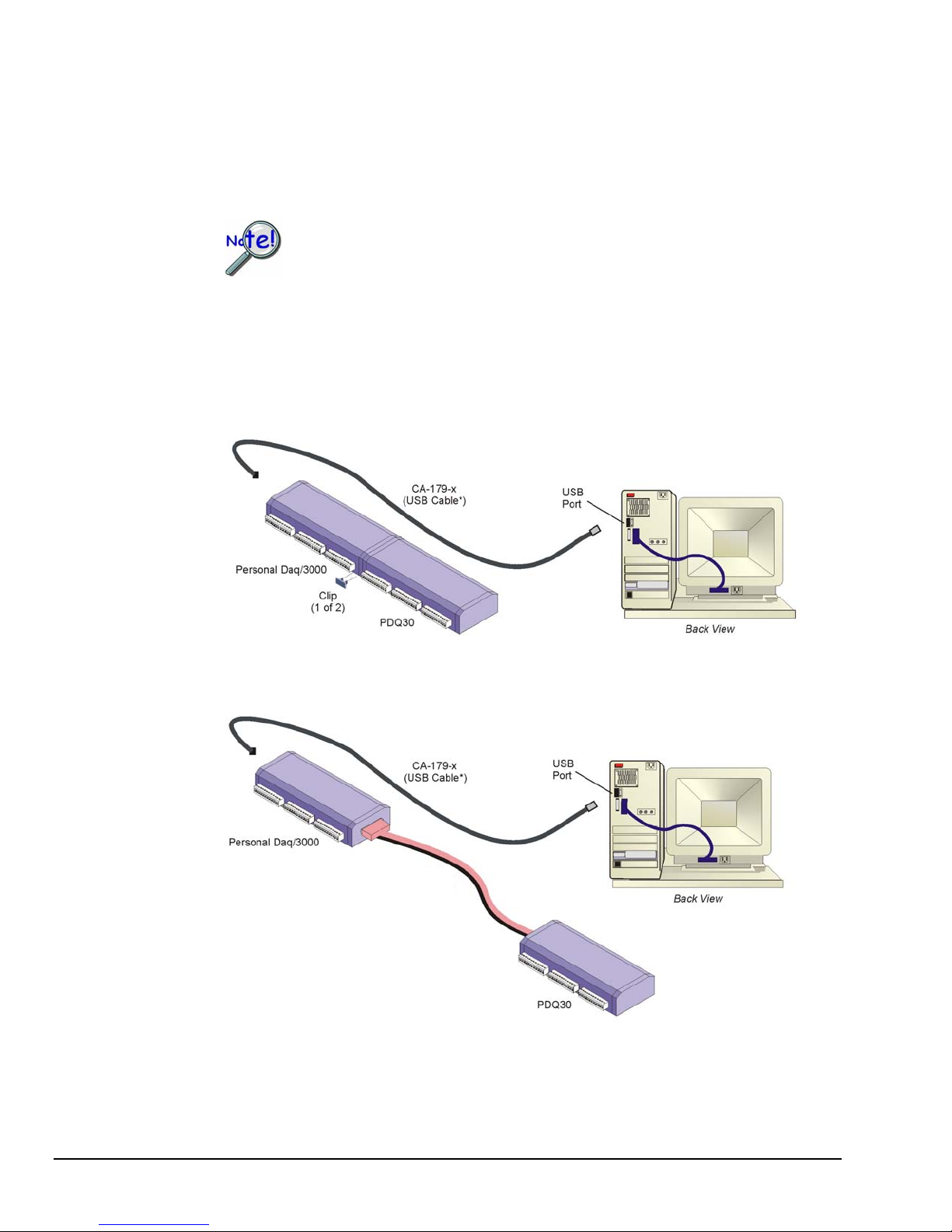
(b) Add le. the PDQ30 Expansion Option, if applicab
PDQ30 is not to be connected to a live device. Unplug the USB
cable from the
host PC prior to connecting the PDQ30.
PDQ30 is n optional analog expansion module that can be used to add an additional 48 SE
(or 24 DE)
Personal 3000 Series modules can connect to a PDQ30, directly via mating DB25 connectors
as indicat n the following figure; or indirectly via a CA-96A cable, as indicated in the second
figure. When connected directly, i.e., DB25 to DB25, two small clips (included) are used to h
a
analog inputs.
Daq/
ed i
old
the modules together.
Direct Connection of Personal Daq/3000 and PDQ30
* Do not connect the CA-179-x USB cable until step 2d.
CA-96A
Cable
Connection of Personal Daq/3000 and PDQ30 via a CA-96A Expansion Cable
* Do not connect the CA-179-x USB cable until step 2d.
Note: In the figures, the “x” after “CA-179-” indicates the cable length (1, 3, or 5 meters).
IG-4
957593 Personal Daq/3000 Series Installation Guide
 Loading...