

Page 1

Personal488
User's Manual
For Windows® 95/98/Me/NT/2000
the smart approach to instrumentation
™
IOtech, Inc.
25971 Cannon Road
Cleveland, OH 44146-1833
Phone: (440) 439-4091
Fax: (440) 439-4093
E-mail: sales@iotech.com
Internet: www.iotech.com
Personal488
User's Manual
For Windows 95/98/Me/NT/2000
p/n
495-0903
Rev.
3.0
© 2000, 2001 by IOtech, Inc. April 2001 Printed in the United Stat es of America
Page 2

ii
Personal488 User’s Manual for Windows95/98/Me/NT/2000
Page 3
Warranty Information
Your IOtech warranty is as stated on the product warranty card. You may contact IOtech by phone,
fax machine, or e-mail in regard to warranty-related issues.
Phone: (440) 439-4091, fax: (440) 439-4093, e-mail: sales@iotech.com
Limitation of Liability
IOtech, Inc. cannot be held liable for any damages resulting from the use or misuse of this product.
Copyright, Trademark, and Licensing Notice
All IOtech documentation, software, and hardware are copyright with all rights reserved. No part of this product may be
copied, reproduced or transmitted by any mechanical, photographic, electronic, or other method without IOtech’s prior written
consent. IOtech product names are trademarked; other product names, as applicable, are trademarks of their respective
holders. All supplied IOtech software (including miscellaneous support files, drivers, and sample programs) may only be used
on one installation. You may make archival backup copies.
FCC Statement
IOtech devices emit radio frequency energy in levels compliant with Federal Communications Commission rules (Part 15) for
Class A devices. If necessary, refer to the FCC booklet How To Identify and Resolve Radio-TV Interference Problems (stock #
004-000-00345-4) which is available from the U.S. Government Printing Office, Washington, D.C. 20402.
CE Notice
Many IOtech products carry the CE marker indicating they comply with the safety and emissions standards of the
European Community. As applicable, we ship these products with a Declaration of Conformity stating which
specifications and operating conditions apply.
Warnings, Cautions, Notes, and Tips
Refer all service to qualified personnel. This caution symbol warns of possible personal injury or equipment damage
under noted conditions. Follow all safety standards of professional practice and the recommendations in this manual.
Using this equipment i n ways other than described in t his manual can present serious safety hazards or cause equipment
damage.
This warning symbol is used in this manual or on the equipment to warn of possible injury or death from electrical
shock under noted conditions.
This ESD caution symbol urges proper handling of equipment or components sensitive to damage from electrostatic
discharge. Proper handling guidelines include the use of grounded anti-static mats and wrist straps, ESD-protective
bags and cartons, and related procedures.
This symbol indicates the message is important, but is not of a Warning or Caution category. These notes can be of
great benefit to the user, and should be read.
In this manual, the book symbol always precedes the words “Reference Note.” This type of note identifies the location
of additional information that may prove helpful. References may be made to other chapters or other documentation.
Tips provide advice that may save time during a procedure, or help to clarify an issue. Tips may include additional
reference.
Specifications and Calibration
Specifications are subject to change without notice. Significant changes will be addressed in an addendum or revision to the
manual. As applicable, IOtech calibrates its hardware to published specifications. Periodic hardware calibration is not
covered under the warranty and must be performed by qualified personnel as specified in this manual. Improper calibration
procedures may void the warranty.
Quality Notice
IOtech has maintained ISO 9001 certification since 1996. Prior to shipment, we thoroughly test our products and
review our documentation to assure the highest quality in all aspects. In a spirit of continuous improvement, IOtech
welcomes your suggestions.
Personal488 User’s Manual for Windows95/98/Me/NT/2000 iii
Page 4

Your order was carefully inspected prior to shipment. When you receive your system,
carefully unpack all items from the shipping carton and check for physical signs of damage
that may have occurred during shipment. Promptly report any damage to the shipping agent
and your sales representative. Retain all shipping materials in case the unit needs to be
returned to the factory.
iv
Personal488 User’s Manual for Windows95/98/Me/NT/2000
Page 5

Table of Contents
1 – Personal488 Overview …… 1-1
2 – CD-ROM, Driver 488 Software Packages …… 2-1
3 – Installation …… 3-1
Windows® 95 Users …… 3-3
Windows
Windows
Windows
Windows
4 – Hardware Configuration Reference …… 4-1
PCI488 Users - Automatic Configuration …… 4-1
AT488pnp Users - Automatic Configuration …… 4-1
CARD488 Users - Automatic Configuration …… 4-1
AT488 Configurations …… 4-3
GP488B Configurations …… 4-6
GP488B/MM Configurations …… 4-9
5 – Using IEEE488 …… 5-1
IEEE488 Configuration Utility …… 5-1
WinTest – Driver488 WorkShop …… 5-4
Differences between 32-bit and 16-Bit Driver488 Software …… 5-10
Programming Language Support …… 5-10
®
98 Users …… 3-9
®
Me Users…… 3-15
®
NT Users …… 3-21
®
2000 Users …… 3-23
Microsoft Visual C++ …… 5-10
Borland C++ …… 5-11
Microsoft Visual BASIC …… 5-12
Borland Delphi …… 5-13
Support for Other Languages …… 5-13
16-Bit Driver488/W95 Compatibility Layer …… 5-13
6 – API Reference …… 6-1
Appendices
A – API Error Codes …… A-1
B – IEEE488 ASCII Code Map …… B-1
C – Troubleshooting …… C-1
The IEEE 488 Bus Standard …… C-1
Analyzing the IEEE Bus …… C-2
Common Problems and Solutions …… C-3
New Standards Simplify Programming …… C-6
Frequently Asked Personal 488 Questions …… C-7
D – Specifications …… D-1
PCI488 Specifications …… D-1
AT488pnp Specifications …… D-1
CARD488 Specifications …… D-1
AT488 Specifications …… D-2
GP488B Specifications …… D-2
GP488B/MM Specifications …… D-2
E – National Instruments—Compatible Drivers …… E-1
Overview …… E-1
Program Requirements …… E-1
Installation …… E-2
Upgrading from a Previous Version …… E-2
Miscellaneous Hints and Tips …… E-2
File Structure …… E-2
Personal488 User’s Manual for Windows95/98/Me/NT/2000
04-10-01
v
Page 6

vi
04-10-01
Personal488 User’s Manual for Windows95/98/Me/NT/2000
Page 7
Personal488 Overview 1
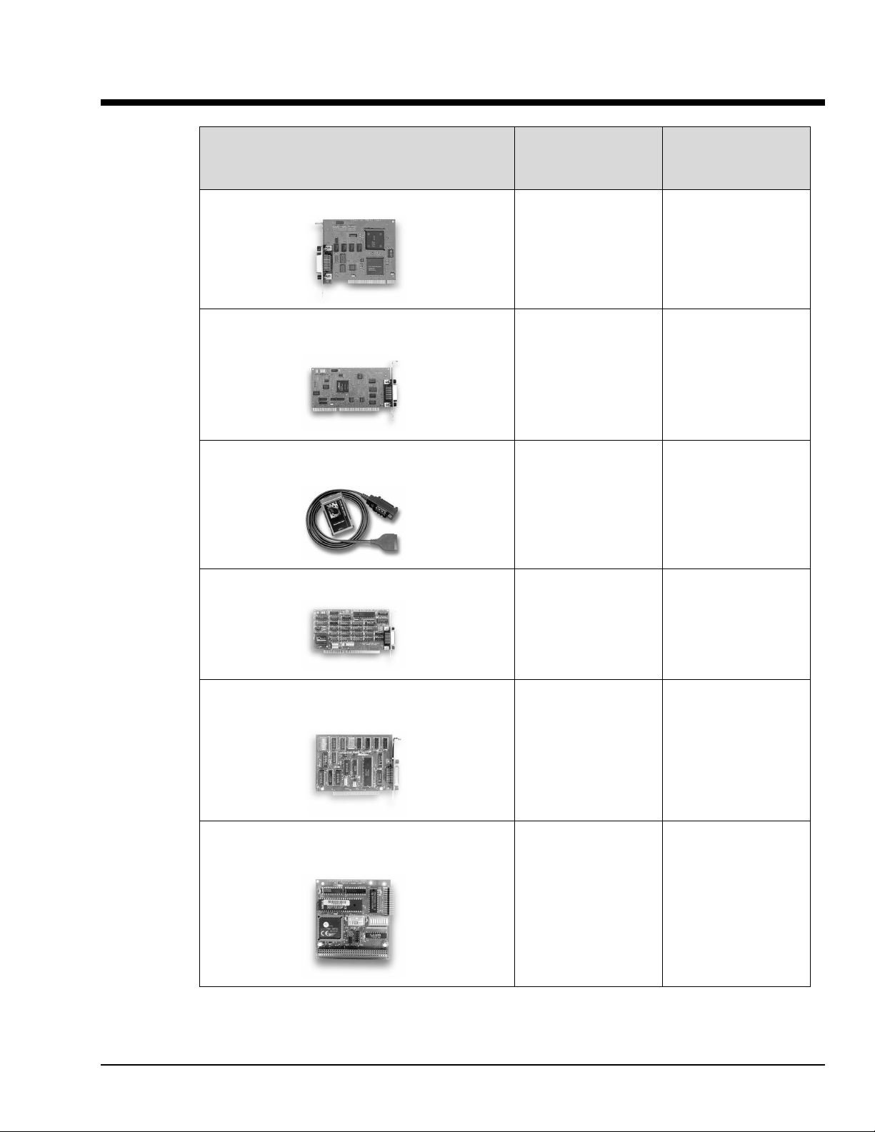
Personal488 Hardware Plug-and-Play Bus Type and
Transfer Rate
Personal488/PCI (with PCI488)
Yes 32-bit PCI Bus
1 Mbyte/s
Personal488/ATpnp
(with AT488pnp)
Personal488/CARD
(with CARD488)
Personal488/AT (with AT488)
Personal488
(with GP488B
*
)
Yes 16-bit ISA Bus
1 Mbyte/s
Yes “hot swapping”
PC Card (PCMCIA)
1 Mbyte/s
No 16-bit ISA-bus
1 Mbyte/s
No 8-bit ISA-bus
330 Kbyte/s
Personal488/MM
(with GP488B/MM)
* GP488 boards with serial numbers of 036731 or lower are not supported by Drivers for Windows 9x or
WindowsNT.
Note: Items pictured are not shown to the same scale.
Personal488 for Windows 95/98/Me/NT/2000
*
04-10-01
No 8-bit PC/104
330 Kbyte/s
Personal488 Overview 1-1
Page 8
Hardware Products
The family of Personal488 PC/IEEE 488 controller interfaces includes the six (6) interfaces which are
discussed in this manual. All of them are IEEE 488.2 compatible and are supported by 32-bit Driver488
software for Windows 95, 98, Me, 2000 and NT. These interfaces are discussed in the following
Personal488 packages:
Hardware Configurations
Plug-and-Play Devices
•
Personal488/PCI (PCI488)
•
Personal488/ATpnp (AT488pnp)
•
Personal488/Card (Card488)
Software Installation
The installation process consists of running an installation setup program, and for non plug-and-play
products running the Add New Hardware program found in the Windows Control Panel. The installation
setup program will automatically determine the version of Windows (e.g. Windows 95, 98, Me, NT, or
2000) and copy all the necessary drivers and support files to the appropriate destinations.
“Non plug-and-play” Devices
•
Personal488/AT (AT488)
•
Personal488 (GP488B)
•
Personal488/MM
Reference Note:
•
Refer to Chapter 4, Hardware Configuration Reference for information concerning
jumpers and switches.
•
Refer to Appendix D for hardware specifications.
Install the software before installing the hard ware. Since the insta llation setup program
installs driver and INF files, plug-and-play bo a r ds will be automatically configured upon first
startup, thus eliminating the need to insert the CD and browse for support files. For non
plug-and-play devices all that is required to complete the installation i s to r un “Add New
Hardware.” This will notify Windows that a new device exists.
: For installing Adobe Acrobat Reader. Documentation that has been
Acrobat
included on the CD in the Adobe pdf format, can be viewed and printed with use
of the Adobe Reader.
Driver488/DRV
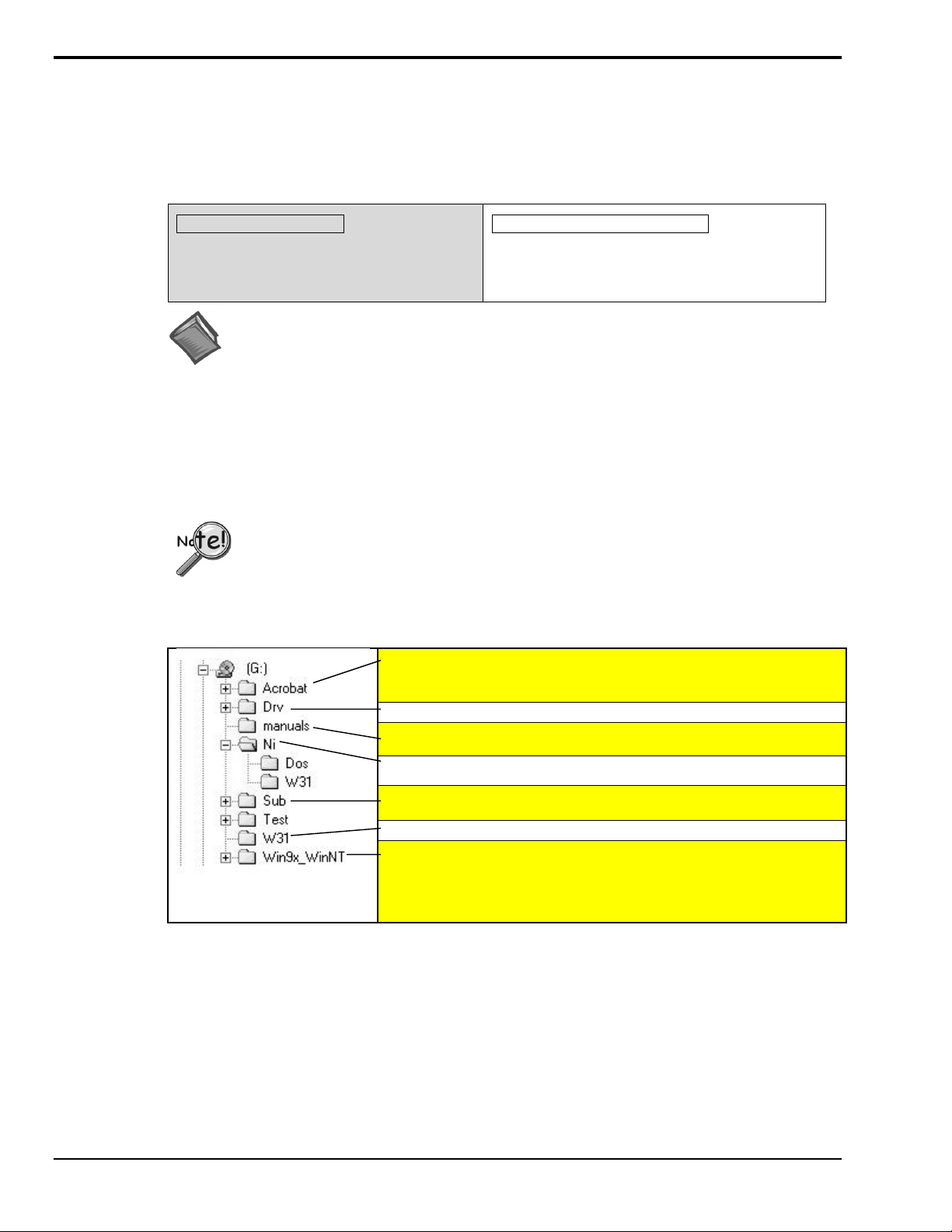
The manuals folder typically contains a .pdf version of the Personal488 User’s
Manual. The Adobe Acrobat Reader is needed to print or read pdf files.
Driver488/NI
Note: The CD structure is subject to change without notice.
1-2 Personal488 Overview
CD Structure
Driver488/SUB
Driver488/W31
The
Win9x_WinNT
2000.
: On Windows systems with AutoPlay
Note
folder includes drivers for Windows 95, 98, Me, NT, and
automatically start upon insertion of the CD.
04-10-01
enabled
Personal488 for Windows 95/98/Me/NT/2000
, the setup program will
Page 9
CD-ROM, Driver 488 Software Packages 2
IOtech, Inc. IEEE 488.2 Software Products
Personal488/PCI – 1 Mbyte/s PCI/IEEE 488.2 Board with Plug & Play, Digital I/O, & Software for PCs
Personal488/Atpnp – 1 Mbyte/s PCI/IEEE 488.2 Board with Plug & Play, Digital I/O, & Software for PCs
Personal488/AT – 1 Mbyte/s IEEE 488.2 Board & Software for PC/Ats
Personal488 – IEEE 488.2 Board & Software for PCs
Personal488/CARD– IEEE 488.2 PC-Card Interface, Cable, & Software for Notebook & Desktop PCs
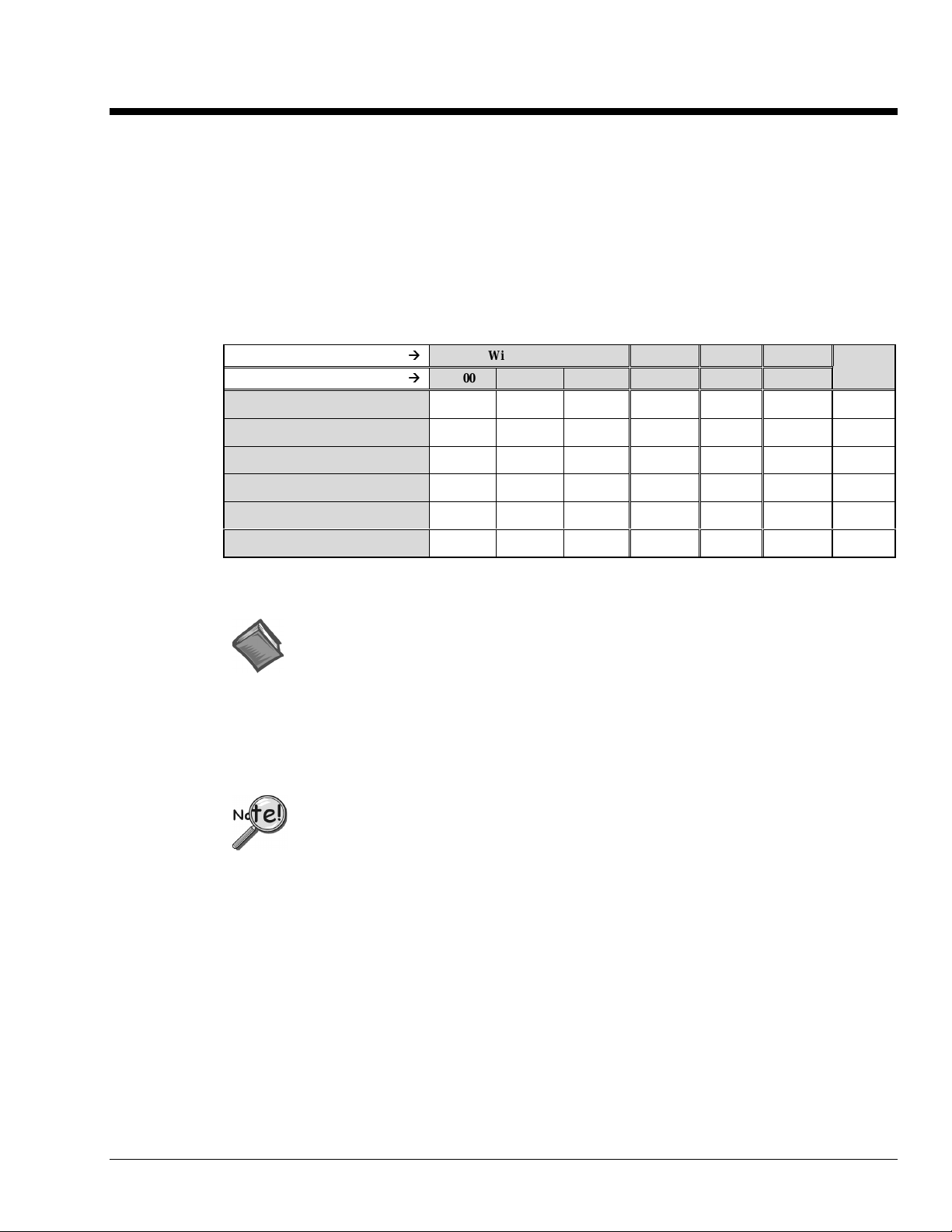
This CD contains several driver software packages for DOS and Windows. The following table shows
which Driver488 packages can be used with each IEEE 488 Controllers product type.
Folder (In CD Root Directory)
Supported Operating System
Personal488 (ISA)
Personal488AT (ISA)
Personal488/Atpnp (ISA pnp)
Personal488PCI (PCI)
Personal488CARD (PC-CARD)
Personal 488MM (PC104)
Æ
Æ
Æ
Æ
Win9x_WinNT W31 DRV SUB
2000 9x & Me NT 3x DOS DOS
NI
(Note1)
''' ''''
''' ''''
''
'''
''
No No No No
No No No
No
''''
'
'
''' ''''
Note 1: Information pertaining to National Instruments (NI) is provided in Appendix E.
Reference Note:
Refer to Appendix E for National Instruments in formation.
The CD contains all of the Driver488 packages available for current IEEE 488 Controller products. The
various driver packages are organized according to the directory tree structure shown below. The location
of each package is shown below, along with the name of the installation program in each directory.
Before running any of the installation programs, please look for a rea d-me file in the same
directory as the install program. When present, it may contain important installation
instructions.
Personal488 for Windows 95/98/Me/NT/2000
04-10-01
CD-ROM, Driver 488 Software Packages 2-1
Page 10

Driver488 Packages
Driver488/DRV
IEEE 488.2 DOS Device Driver Software.
•
Supports IOtech's AT488, GP488B, CARD488, NB488, GP488B/MM, MP488, MP488CT series
boards.
•
Includes "ON SRQ" program vectoring for Basic, C, Pascal.
•
Compatible with all popular programming languages and spreadsheets.
•
Automatically loads into high memory when available.
Driver488/SUB
IEEE 488.2 DOS Subroutine Driver.
•
Supports IOtech's AT488, GP488B, CARD488, NB488, GP488B/MM, MP488, MP488CT series
boards.
•
Includes "ON SRQ" program vectoring for Basic, C, Pascal.
•
Compatible with popular programming languages and spreadsheets such as C, Pascal and QuickBasic.
Driver488/W31
IEEE 488.2 Microsoft Windows Dynamic Link Library
•
Supports IOtech's AT488, GP488B, CARD488, NB488, GP488B/MM, MP488, MP488CT series
boards.
•
Offers HP-style commands for high & low-level control.
•
Designed for Windows' message passing, multi-tasking architecture.
•
Includes language interfaces for Microsoft C, Visual C++, Visual Basic, Turbo C, Borland C++.
•
Includes an interactive control application for exercising instruments and generating code.
•
On-Line Help provides complete command reference as well as examples.
Win9x_WinNT Folder
This folder includes IEEE 488.2 drivers for the following operating systems: Windows 9x, Windows Me,
Windows 2000, and Windows NT.
The setup program automatically detects the operating system and installs the correct drivers.
In regard to Windows 9x, Windows Me, and Windows 2000, the drivers
•
Support IOtech's AT488, GP488B, GP488B/MM, PCI488 series boards.
•
Integrate IEEE 488.2 control into Microsoft Windows applications.
•
Provide true multi-tasking device locking.
•
Were specifically designed for the 32-bit Windows environment.
2-2 CD-ROM, Driver 488 Software Packages
04-10-01
Personal488 for Windows 95/98/Me/NT/2000
Page 11
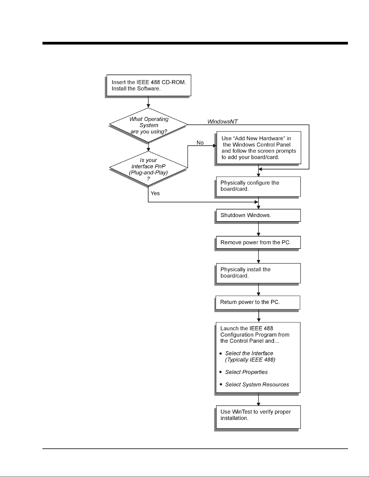
Installation 3
I
EEE 488 Installation Flowchart
Windows95/98
/Me/2000
Windows® 95 Users …… 3-3
®
Windows
Windows
Windows
Windows
Personal488 for Windows 95/98/Me/NT/2000
98 Users …… 3-9
®
Me Users …… 3-15
®
NT Users …… 3-21
®
2000 Users …… 3-23
04-10-01
Installation 3-1
Page 12

3-2 Installation
04-10-01
Personal488 for Windows 95/98/Me/NT/2000
Page 13

Windows 95 Users
Software Installation
Step 1
Insert the IEEE488 Software CD. The CD has an auto-run program that will automatically start the
setup program when the CD is inserted into the CD ROM driver. If auto-run is disabled, use Explorer to
launch the Setup.exe found in the root directory of the CD. Follow the screen prompts to install the
software. If non plug-and-play hardware is being installed, proceed to step 2; otherwise proceed to
“Hardware Installation” on page 3-7.
Step 2
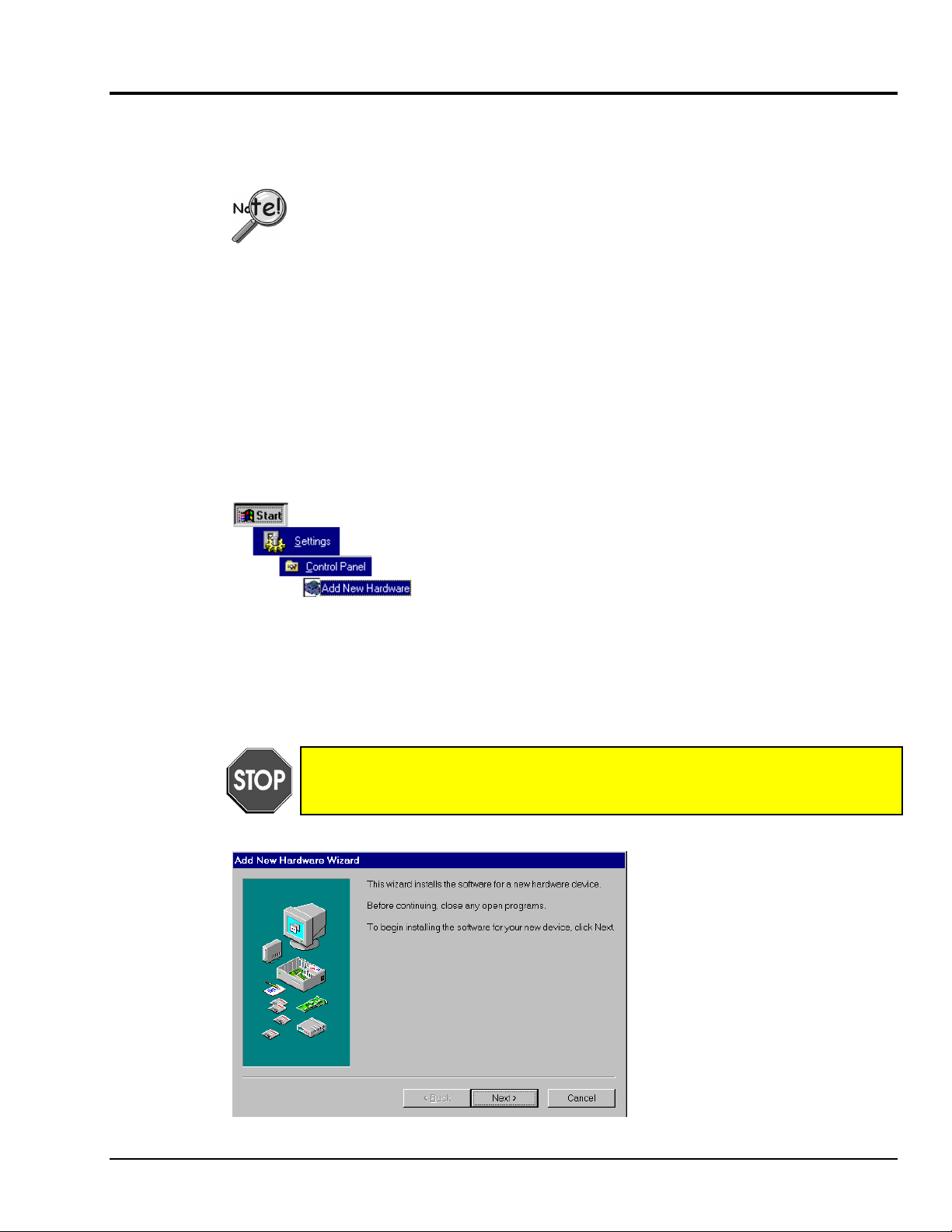
Use the “Add New Hardware” program found in the Control Panel to notify Windows 95 that you are
installing new hardware. Refer to the following steps that demonstrate the typical Windows panels
encountered during the “Add New Hardware” program execution:
•
For best results, install the interface after the software installation.
•
Due to differences in Windows 95 “Add New Hardware” panels, the following
description may vary slightly.
•
If installing a second non plug-and-play interface, skip step 1.
•
If installing a second plug-and-play interface, go to “Hardware Installation.”
Start ⇒ Settings ⇒ Control Panel ⇒ Add New Hardware
Personal488 for Windows 95/98/Me/NT/2000
04-10-01
Installation 3-3
Page 14
Windows 95
Add New Hardware Procedure (non plug-and-play users only):
It is only necessary for users of “non plug-and-play” boards to follow the Add New
Hardware Procedure. If your device is a “plug-and-play device,” skip this procedure.
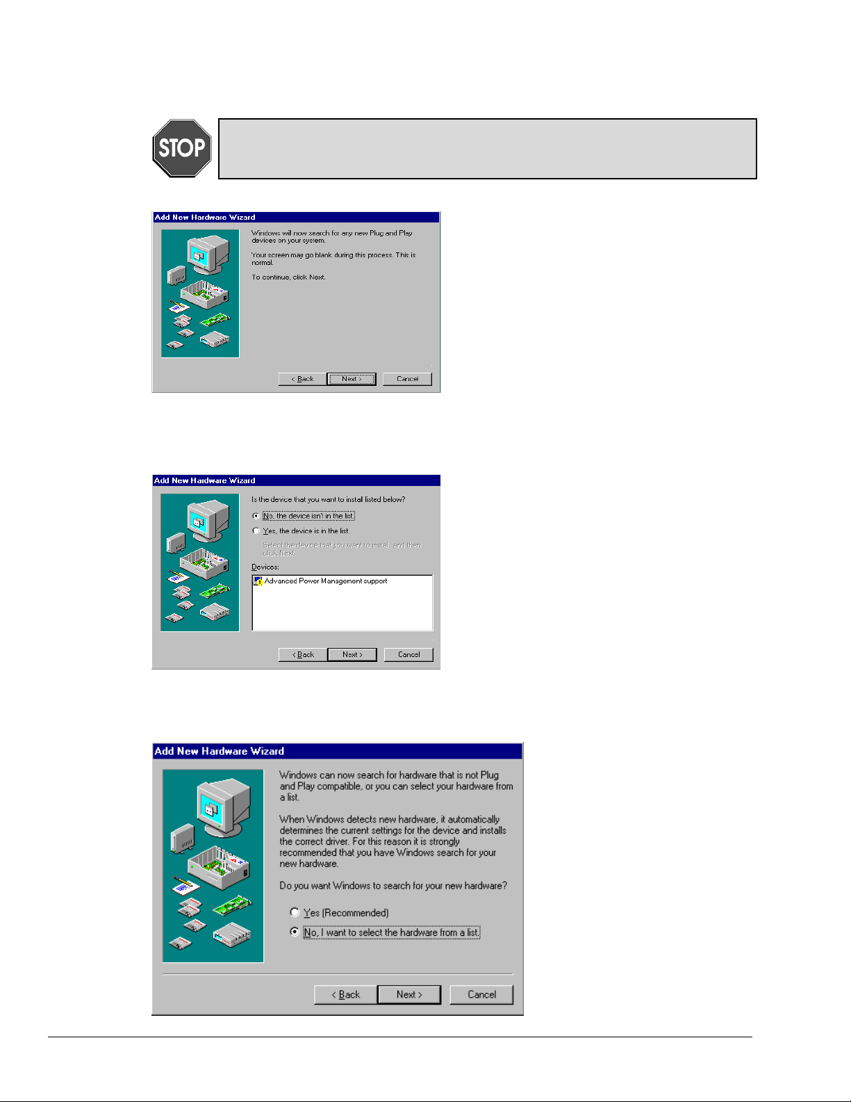
1. The “Add New Hardware Wizard” displays
an introductory message and prompts you to
click Next.
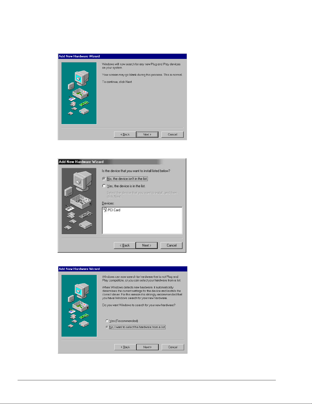
2. Windows 95 will automatically search for
hardware. Click Next.
3. Click ‘No, the device isn’t in the list’
4. Select the option:
“No, I want to select the
hardware from a list,” then
click Next.
3-4 Installation
04-10-01
Personal488 for Windows 95/98/Me/NT/2000
Page 15
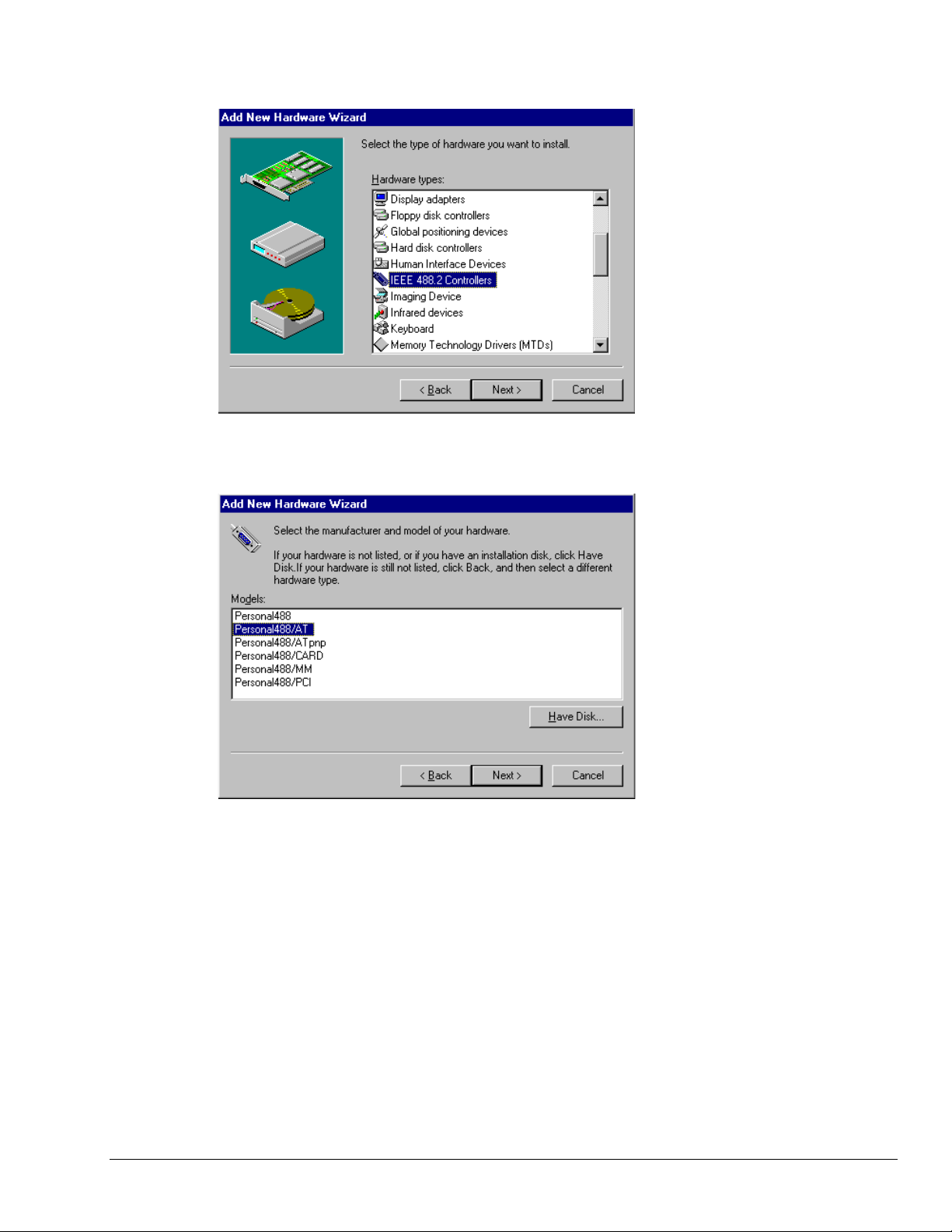
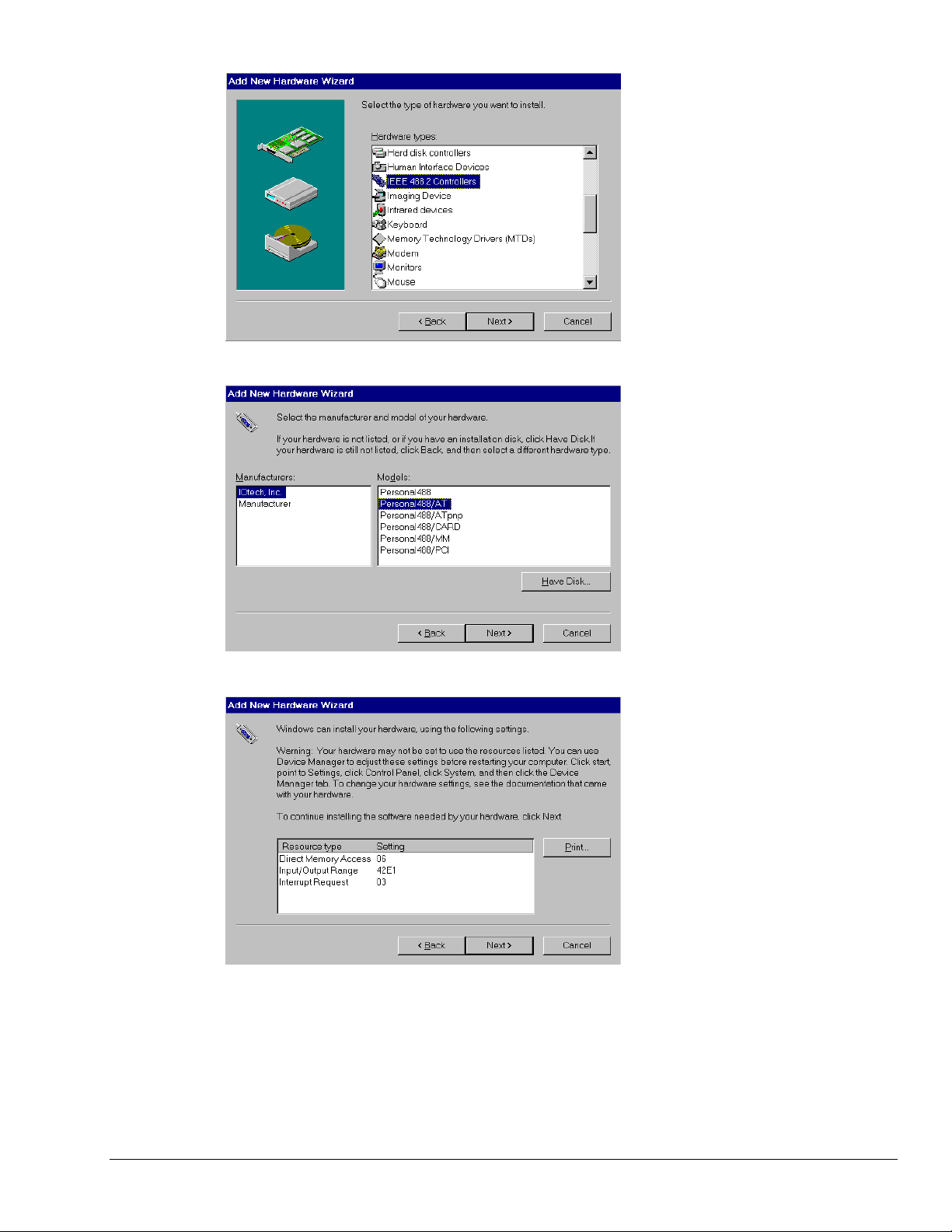
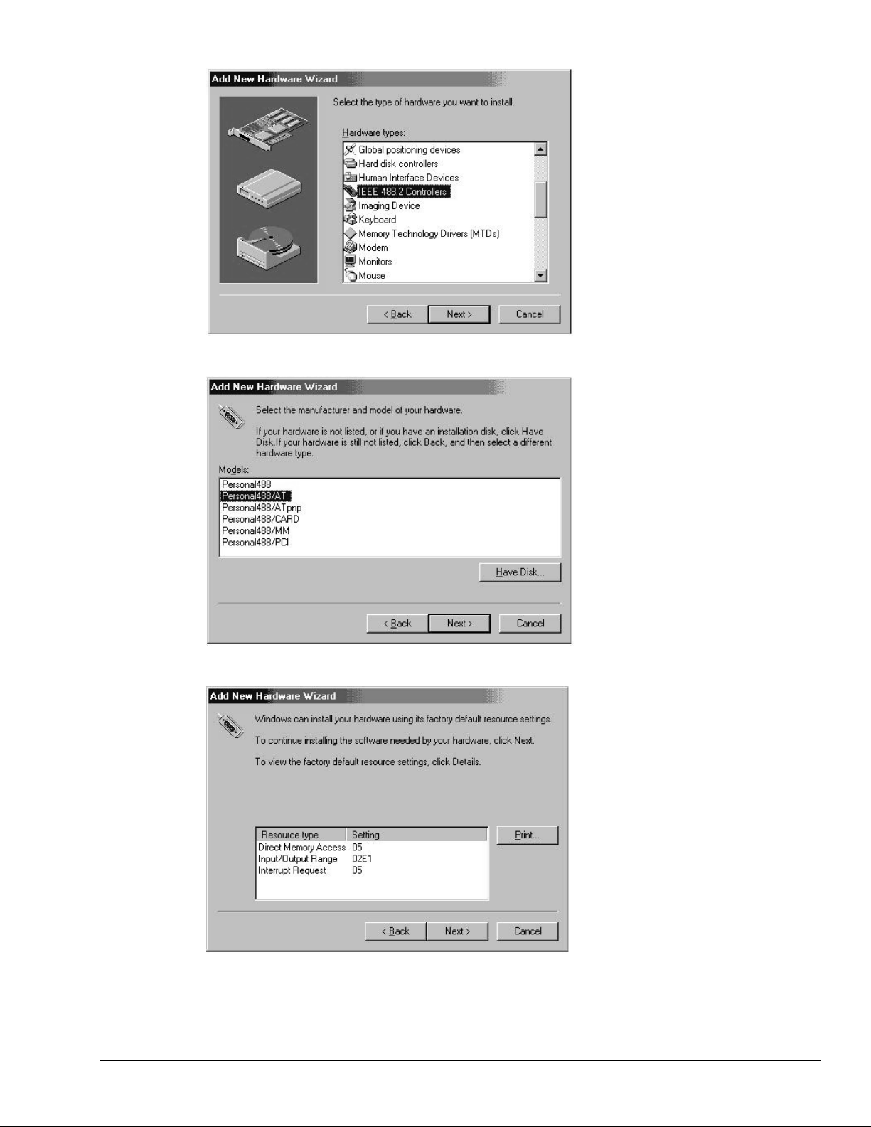
Windows 95
5. Choose IEEE488.2
Controllers from the list of
hardware types and click
Next.
6. Windows will now display a
list of devices to install.
Select your specific
Personal488 interface
product.
After making the selection,
click Next.
Windows will now display the
default resource settings for
your interface.
Personal488 for Windows 95/98/Me/NT/2000
04-06-01
Installation 3-5
Page 16

Windows 95
7. Make note of the displayed
settings, as you mus t conf ig ur e
the jumpers and switch settings
before installing an AT488 or
GP488B
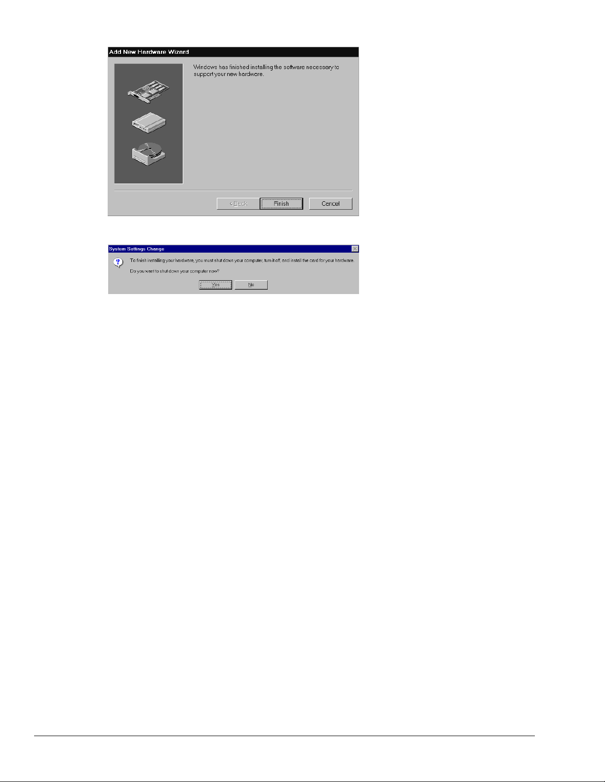
8. Click Finish.
3-6 Installation
04-10-01
9. Click Yes, proceed with
Windows 95 Hardware
Installation.
Personal488 for Windows 95/98/Me/NT/2000
Page 17

Hardware Installation for Windows 95 Users
Plug-and-Play Devices
Personal488/PCI
Personal488/ATpnp
Personal488/Card
1. If you have not already done so, shutdown Windows 95 after the IEEE 488 software has been
successfully installed.
2. Remove po wer from the PC.
3. Physically install your interface. As a quick reference,
Personal488/PCI installs into a 32-bit PCI expansion slot,
Personal488/ATpnp installs into a 16-bit ISA expansion slot, and
Personal488/Card installs into a PC card slot.
4. Return power to the PC. After the computer powers up, Windows will detect your new hardware.
This completes the installation procedure.
“Non plug-and-play” Devices
Personal488/AT (AT488)
Personal488 (GP488Bplus)
Personal488/MM
Windows 95
1. Verify that Windows 95 has properly shutdown.
2. Remove po wer from the PC.
3. Physically configure the device’s jumpers and switches to match the resource settings Windows
reported during the driver installation.
Non plug-and-play board users: physically configure your board’s jumpers and switches
to match the resource settings Windows reported. If these settings conflict with other
hardware, change the jumpers, switches, and Windows Resource settings to available
resources.
Reference Note:
Refer to Chapter 4, Hardware Configuration Reference for further informati on
concerning jumpers and switches.
4. Physically install your interface.
5. Return power to the PC.
This completes the installation procedure.
Reference Note:
See page 5-5 for instructions on running WinTest to verif y pr oper installation.
Personal488 for Windows 95/98/Me/NT/2000
04-06-01
Installation 3-7
Page 18

Windows 95
3-8 Installation
04-10-01
Personal488 for Windows 95/98/Me/NT/2000
Page 19

Windows 98 Users
Software Installation
Step 1
Insert the IEEE488 Software CD. The CD has an auto-run program that will automatically start the
setup program when the CD is inserted into the CD ROM driver. If auto-run is disabled, use Explorer
to launch the Setup.exe found in the root directory of the CD. Follow the screen prompts to install the
software. Then, if non plug-and-play hardware is being installed, proceed to step 2; otherwise proceed
to hardware installation on page 3-13.
Step 2
Use the “Add New Hardware” program found in the Control Panel to notify Windo ws 98 that you are
installing new hardware. Refer to the following steps that demonstrate the typical Windows panels
encountered during the “Add New Hardware” program execution:
•
For best results, install the interface after the software installation.
•
If installing a second non plug-and-play interface, skip step 1.
•
If installing a second plug-and-play interface, go to Hardware Installation , page 3-13.
Start ⇒ Settings ⇒ Control Panel ⇒ Add New Hardware
Add New Hardware Procedure (
It is only necessary for users of “non plug-and-play” boards to follow the Add New
Hardware Procedure. If your device is a “plug-and-play device,” skip this procedure.
non plug-and-play users only
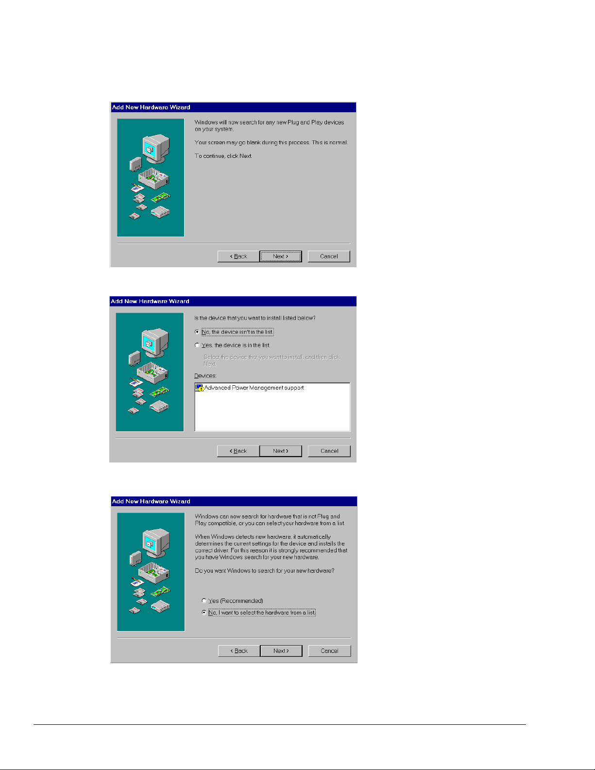
1. The “Add New Hardware Wizard”
):
displays an introductory message
and prompts you to click Next.
Personal488 for Windows 95/98/Me/NT/2000
04-10-01
Installation 3-9
Page 20
Windows 98
2. Click Next.
3. Select ‘No, the device isn’t in the
list’ and click Next.
3-10 Installation
04-10-01
4. Select ‘No, I want to select the
hardware from a list’ and click
Next.
Personal488 for Windows 95/98/Me/NT/2000
Page 21
Windows 98
5. Select ‘IEEE 488.2 Controllers’ and
click Next.
6. Windows will now display a list of
devices to install. Select your
specific Personal488 interface
product.
7. After making the selection,
click Next.
Windows will now display the default
resource settings for your interface.
8. Make note of the displayed settings,
as you must configure the jumpers
and switch settings before installing
an AT488 or GP488B.
Personal488 for Windows 95/98/Me/NT/2000
04-06-01
Installation 3-11
Page 22
Windows 98
9. Click Finish.
10. Click ‘Yes’ and shut down the
computer; then proceed to the next
step.
3-12 Installation
04-10-01
Personal488 for Windows 95/98/Me/NT/2000
Page 23

Hardware Installation for Windows 98 Users
Plug-and-Play Devices
Personal488/PCI
Personal488/ATpnp
Personal488/Card
1. If you have not already done so, shutdown Windows 98 after the IEEE 488 software has been
successfully installed.
2. Remove po wer from the PC.
3. Physically install your interface. As a quick reference,
Personal488/PCI installs into a 32-bit PCI expansion slot,
Personal488/ATpnp installs into a 16-bit ISA expansion slot, and
Personal488/Card installs into a PC card slot.
4. Return power to the PC. Windows will detect your new hardware when the computer po wers up.
This completes the installation procedure.
“Non plug-and-play” Devices
Personal488/AT (AT488)
Personal488 (GP488B)
Personal488/MM
Windows 98
1. If you have not already done so, shutdown Windows 98 after the IEEE 488 software has been
successfully installed.
2. Remove po wer from the PC.
3. Physically configure the device’s jumpers and switches to match the resource settings Windows
reported during the driver installation.
Non plug-and-play board users: physically configure your board’s jumpers and switches
to match the resource settings Windows reported. If these settings conflict with other
hardware change the jumpers, switches, and Windows Resource settings to available
resources.
Reference Note:
Refer to Chapter 4, Hardware Configuration Reference for further information concer ning
jumpers and switches.
4. Return power to the PC.
This completes the installation procedure.
Personal488 for Windows 95/98/Me/NT/2000
04-06-01
Installation 3-13
Page 24

Windows 98
3-14 Installation
04-10-01
Personal488 for Windows 95/98/Me/NT/2000
Page 25
Windows Me Users
Software Installation
Step 1
Insert the IEEE488 Software CD. The CD has an auto-run program that will automatically start the
setup program when the CD is inserted into the CD ROM driver. If auto-run is disabled, use Explorer
to launch the Setup.exe found in the root directory of the CD. Follow the screen prompts to install the
software. Then if non plug-and-play hardware is being installed, proceed to step 2; otherwise proceed
to Hardware Installation for Windows Me Users on page 3-19.
Step 2
Use the “Add New Hardware” program found in the Control Panel to notify Windows Me that you are
installing new hardware. Refer to the following steps that demonstrate the typical Windows panels
encountered during the “Add New Hardware” program execution:
•
For best results, install the interface after the software installation.
•
If installing a second non plug-and-play interface, skip step 1.
•
If installing a second plug-and-play interface, go to “Hardware Installation.”
Start ⇒ Settings ⇒ Control Panel ⇒ Add New Hardware
Add New Hardware Procedure (
It is only necessary for users of “non plug-and-play” boards to follow the Add New
Hardware Procedure. If your device is a “plug-and-play device,” skip this procedure.
non plug-and-play users only
1. The “Add New Hardware Wizard”
):
displays an introductory message
and prompts you to click Next.
Personal488 for Windows 95/98/Me/NT/2000
04-10-01
Installation 3-15
Page 26
Windows Me
2. Click Next.
3. Select ‘No, the device isn’t in the
list’ and click Next.
3-16 Installation
04-10-01
4. Select ‘No, I want to select the
hardware from a list’ and click
Next.
Personal488 for Windows 95/98/Me/NT/2000
Page 27
Windows Me
5. Select ‘IEEE 488.2 Controllers’ and
click Next.
6. Windows will now display a list of
devices to install. Select your
specific Personal488 interface
product.
7. After making the selection, click
Next.
Windows will now display the
default resource settings for your
interface.
8. Make note of the displayed settings,
as you must configure the jumpers
and switch settings before installing
an AT488 or GP488B.
Personal488 for Windows 95/98/Me/NT/2000
04-06-01
Installation 3-17
Page 28

Windows Me
9. Click Finish.
10. Click ‘Yes’ and shut down the
computer.
At this point, proceed to the next
section, Hardware Installation for
Windows Me Users.
3-18 Installation
04-10-01
Personal488 for Windows 95/98/Me/NT/2000
Page 29

Hardware Installation for Windows Me Users
Plug-and-Play Devices
Personal488/PCI
Personal488/ATpnp
Personal488/Card
1. If you have not already done so, shutdown Windows Me after the IEEE 488 software has been
successfully installed.
2. Remove po wer from the PC.
3. Physically install your interface. As a quick reference,
Personal488/PCI installs into a 32-bit PCI expansion slot,
Personal488/ATpnp installs into a 16-bit ISA expansion slot, and
Personal488/Card installs into a PC card slot.
4. Return power to the PC. After the computer powers up, Windows Me will detect your new hardware.
This completes the installation procedure.
“Non plug-and-play” Devices
Personal488/AT (AT488)
Personal488 (GP488B)
Personal488/MM
Windows Me
1. If you have not already done so, shutdown Windows Me after the IEEE 488 software has been
successfully installed.
2. Remove po wer from the PC.
3. Physically configure the device’s jumpers and switches to match the resource settings Windows Me
reported during the driver installation.
Non plug-and-play board users: physically configure your board’s jumpers and switches
to match the resource settings Windows reported. If these settings conflict with other
hardware change the jumpers, switches, and Windows Resource settings to available
resources.
Reference Note:
Refer to Chapter 4, Hardware Configuration Reference for further information concer ning
jumpers and switches.
4. Return power to the PC.
This completes the installation procedure.
Personal488 for Windows 95/98/Me/NT/2000
04-06-01
Installation 3-19
Page 30

Windows Me
3-20 Installation
04-10-01
Personal488 for Windows 95/98/Me/NT/2000
Page 31

Windows NT Users
Software Installation
Step 1
Insert the IEEE488 Software CD. The CD has an auto-run program that will automatically start the
setup program when the CD is inserted into the CD ROM driver. If auto-run is disabled, use Explorer
to launch the Setup.exe found in the root directory of the CD.
Step 2
Follow the screen prompts to install the software, then proceed to hardware installation.
Hardware Installation
All Devices
Personal488/AT (AT488)
Personal488 (GP488Bplus)
Personal488/MM
Personal488/PCI
1. Access the Windows Control Panel and launch the IEEE488 configuration program.
2. Highlight your interface (typically IEEE0) and select Properties as shown below:
Selecting “Properties” and “System Resources”
3. Click the Systems Resources button.
If Personal488/PCI is selected, then the System Resources button is not available. Windows
NT is not a plug-and-play operating system, and thus changing resources on a Plug-and-Play
interface is not possible.
Personal488 for Windows 95/98/Me/NT/2000
04-10-01
Installation 3-21
Page 32

Windows NT
4. Physically configure the device’s jumpers and switches to match the resource settings Windows is
reporting during the driver installation. If these settings conflict with other hard ware, change the
jumpers, switches, and Windows Resource settings to ava ila ble resources.
Reference Note:
Refer to Chapter 4, Hardware Configuration Reference, for more information
regarding jumpers and switches.
5. Shutdown Windows and remove power from your PC.
6. Insert the interface board, securing it appropriately.
7. Return power to the PC.
This completes the installation procedure.
3-22 Installation
04-10-01
Personal488 for Windows 95/98/Me/NT/2000
Page 33

Windows 2000 Users
Software Installation
•
•
•
Step 1
Insert the IEEE488 Software CD. The CD has an auto-run program that will automatically start the
setup program when the CD is inserted into the CD ROM driver. If auto-run is disabled, use Explorer
to launch the Setup.exe found in the root directory of the CD. Follow the screen prompts to install the
software. Then, if non plug-and-play hardware is being installed, proceed to step 2; otherwise proceed
to hardware installation on page 3-29.
Step 2
Use the “Add New Hardware” program found in the Control Panel to notify Windows 2000 that you
are installing new hardware. Refer to the following steps that demonstrate the typical Windows panels
encountered during the “Add New Hardware” program execution:
For best results, install the interface after the software installation.
If installing a second non plug-and-play interface, skip step 1.
If installing a second plug-and-play interface, go to Hardware Installation , page 3-29.
Start ⇒ Settings ⇒ Control Panel ⇒ Add New Hardware
Add New Hardware Procedure (
It is only necessary for users of “non plug-and-play” boards to follow the Add New
Hardware Procedure. If your device is a “plug-and-play device,” skip this procedure.
non plug-and-play users only
1. After the Add/Remove Hardware
):
Wizard appears, click Next.
Personal488 for Windows 95/98/Me/NT/2000
04-10-01
Installation 3-23
Page 34

Windows 2000
2. Select
Add/Troubleshoot a device.
3. Click Next.
The Add/Remove Hardware Wizard
searches for new plug-and-play hardware.
After new hardware is located a screen,
similar to that at the left, appears.
4. Select
Add a new device.
5. Click Next.
3-24 Installation
04-10-01
Personal488 for Windows 95/98/Me/NT/2000
Page 35

Windows 2000
6. When prompted by the question,
“Do you want Windows to search for
your new har dware?”
Select ‘No, I want to select the
hardware from a list.’
7. Click Next.
8. When asked what type of hardware
you want to install, select
Other devices.
9. Click Next.
Personal488 for Windows 95/98/Me/NT/2000
04-06-01
Windows will display a list of
manufacturers and device models.
11. Select IOtech Inc.
12. Select your specific Personal488
interface product.
13. Click Next.
Installation 3-25
Page 36

Windows 2000
14. Click Next.
Windows 2000 will install software
for the device.
If Windows could not detect any
hardware settings for the device, a
message box informs you that
hardware settings must be entered
(see the following figure).
15. If Windows could not detect any
hardware settings, as indicated by the
message in step 14, enter the settings.
Refer to Hardware Configuration
Reference (chapter 4) for setting
information.
3-26 Installation
04-10-01
16. When prompted that “Windows is
ready to install drivers for your new
hardware,” click Next.
Personal488 for Windows 95/98/Me/NT/2000
Page 37

Windows 2000
Windows wil l inform you that the
hardware was installed.
17. Click Finish.
At this point proceed to the next
section, Hardware Installation for
Windows 2000 Users.
Personal488 for Windows 95/98/Me/NT/2000
04-06-01
Installation 3-27
Page 38

Windows 2000
3-28 Installation
04-10-01
Personal488 for Windows 95/98/Me/NT/2000
Page 39

Hardware Installation for Windows 2000 Users
Plug-and-Play Devices
Personal488/PCI
Personal488/ATpnp
Personal488/Card
1. If you have not already done so, shutdown Windows 2000 after the IEEE 488 software has been
successfully installed.
2. Remove po wer from the PC.
3. Physically install your interface. As a quick reference,
Personal488/PCI installs into a 32-bit PCI expansion slot,
Personal488/ATpnp installs into a 16-bit ISA expansion slot, and
Personal488/Card installs into a PC card slot.
4. Return power to the PC. After the computer powers up, Windows 2000 will detect your new
hardware.
This completes the installation procedure.
“Non plug-and-play” Devices
Windows 2000
Personal488/AT (AT488)
Personal488 (GP488B)
Personal488/MM
1. If you have not already done so, shutdown Windows 2000 after the IEEE 488 software has been
successfully installed.
2. Remove po wer from the PC.
3. Physically configure the device’s jumpers and switches to match the resource settings Windows 2000
reported during the driver installation.
Non plug-and-play board users: physically configure your board’s jumpers and switches
to match the resource settings Windows reported. If these settings conflict with other
hardware change the jumpers, switches, and Windows Resource settings to available
resources.
Reference Note:
Refer to Chapter 4, Hardware Configuration Reference for further information concer ning
jumpers and switches.
4. Return power to the PC.
This completes the installation procedure.
Personal488 for Windows 95/98/Me/NT/2000
04-06-01
Installation 3-29
Page 40

Windows 2000
3-30 Installation
04-10-01
Personal488 for Windows 95/98/Me/NT/2000
Page 41

Hardware Configuration Reference 4
AT488 Configurations …… 4-3
GP488B Configurations …… 4-7
GP488B/MM Configurations …… 4-11
Hardware Configuration
Plug-and-Play Devices
Plug-and-play devices require no physical c onfiguration of hardware. After installing your software and
hardware [as described in Chapters 2 and 3] the configuration is performed automatically. Note that the
plug-and-play devices are listed in the following table as a product reference only. This chapter contains
no useful information concerning plug-and-play devices.
Non Plug-and-Play Devices
The I/O base address, IRQ, and DMA settings of non p lug-and-play devices are determined by the
physical settings of jumpers and DIP switches. This chapter provides the information necessary to
configure these devices.
Plug-and-Play Devices Non Plug-and-Play Devices
PCI488 AT488
Automatic
Configuration.
AT488pnp GP488B
Automatic
Configuration.
CARD488 GP488B/MM
Automatic
Configuration.
See page 4-3.
See page 4-7.
See page 4-11.
Note: The device images are not shown to the same scale.
Personal488 for Windows 95/98/Me/NT/2000
04-09-01
Hardware Configuration Reference 4-1
Page 42

4-2 Hardware Configuration Reference
04-09-01
Personal488 for Windows 95/98/Me/NT/2000
Page 43

AT488 Configurations
The I/O base address, IRQ, and DMA settings are switch/jumper selectable via the following locations on
the AT488 interface board: One 2-microswitch DIP switch labelled S1, one 4-microswitch DIP switch
labelled S2, two 14-pin headers labelled DACK and DRQ, and one 22-pin header labelled IRQ. The DIP
switch settings, and the arrangement of the jumpers on the headers set the hardware configuration.
For the next steps, make sure that the I/O address, IRQ, and DMA set on the interface board are different
from any existing ports in your system. A conflict results when two I/O addresses, IRQs, or DMAs are
the same. (As the exception, additional AT488 interfaces may share the same IRQ and DMA values.) If
there is a conflict, reconfigure the switch/jumper settings. Refer to the following figures as needed.
Configuring the AT488 Interface I/O Base Address
S1
1 2 1 2
Base Address
02E1
OPEN OPEN
DACK
DRQ
5 6 7 0 1 2 3
DMA 16-Bit Channel 5
AT488 Default Settings
The factory default I/O base address is
S2
IR Q
1 2 3 4
OPEN
34567
Interrupt Level 5
02E1
. If this creates a conflict, reset switch S1 according to the
Inter ru pt
Level 5
9
1011121415
S1
1 2
OPEN
1 2
OPEN
42E1
AT488 I/O B ase
A ddress S elec tions
22E102E1
1 2
OPEN
62E1
figure and following table. The register addresses will be automatically relocated at fixed offsets from the
base address. If reset, record the new Input/Output (I/O) address being used.
Selected I/O Base
Register
Address
02E1 22E1 42E1 62E1
Automatic Offset Addresses
02E1 22E1 42E1 62E1
06E1 26E1 46E1 66E1
0AE1 2AE1 4AE1 6AE1
0EE1 2EE1 4EE1 6EE1
12E1 32E1 52E1 72E1
16E1 36E1 56E1 76E1
1AE1 3AE1 5AE1 7AE1
1EE1 3EE1 5EE1 7EE1
Read Register Write Register
Data In Data Out
Interrupt Status 1 Interrupt Mask 1
Interrupt Status 2 Interrupt Mask 2
Serial Poll Status Ser ial Poll Mode
Address Status Address Mode
CMD Pass Through Auxiliary Mode
Address 0 Address 0/1
Address 1 End of String
The I/O base address sets the addresses used by the computer to communicate with the IEEE 488 interface
hardware on the board. The address is normally specified in hexadecimal and can be
62E1
. The registers of the IOT7210 IEEE 488 controller chip and other auxiliary registers are then located
at fixed offsets from the base address.
Most versions of Driver488 are capable of managing as many as four IEEE 488 interfaces. To do so, the
interface configurations must be arranged to avoid conflict amongst themselves. No two boards may have
the same I/O address; but they may, and usually should, have t he same DMA channel and interrupt level.
Personal488 for Windows 95/98/Me/NT/2000
04-09-01
02E1, 22E1, 42E1
Hardware Configuration Reference 4-3
, or
Page 44

Configuring the AT488 Interface Interrupt (IRQ)
S2
IR Q
S2
IR Q
1 2 3 4 1 2 3 4
OPEN OPEN
3
4
5
6
7
9
10
11
12
14
15
In te r rup t
Level 3
In te r rup t
Level 4
1 2 3 4
OPEN
Interrupt
Level 5
1 2 3 4
OPEN
In te r rup t
Level 6
1 2 3 4
OPEN
Interrupt
Level 7
1 2 3 4 1 2 3 4 1 2 3 4 1 2 3 4 1 2 3 4
OPEN
3
4
5
6
7
9
10
11
12
14
15
Interrupt
Level 10
OPEN OPEN OPEN OPEN
Interrupt
Level 11
Interrupt
Level 12
Interrupt
Level 14
Interrupt
Level 15
1 2 3 4
OPEN
In te r rup t
Level 9
The factory default Interrupt (IRQ) is 5. If this creates a conflict, reset switch S2 and j u mper IRQ
according to the figure. The switch and jumper settings must both indicate the same interrupt level
for correct operation with interrupts. If reset, record the new Interrupt (IRQ) being used.
The AT488 interface board may be set to interrupt the PC on the occurrence of certain hardware conditions.
The main board interrupt may be set to IRQ level 3 through 7, 9 through 12, 14, or 15. Interrupts 10
through 15 are only available in a 16-bit slot on an AT-class machine. Interrupt 9 becomes synonymous
with Interrupt 2 when used in a PC/XT bus.
The selected interrupt may be shared among several AT488s in the same PC/AT chassis. The AT488
adheres to the “AT-style” interrupt sharing conventions. When the AT488 requires service, the IRQ
jumper determines which PC interrupt level is triggered. When an interrupt occurs, the interrupting device
must be reset by writing to an I/O address which is different for each interrupt level. The switch settings
determine the I/O address to which the board’s interrupt rearm circuitry responds.
4-4 Hardware Configuration Reference
AT488 Interrupt Selections
04-09-01
Personal488 for Windows 95/98/Me/NT/2000
Page 45

Configuring the AT488 Interface DMA Channel
The factory default DMA channel is 5. If this creates a conflict, reset jumpers DACK and DRQ according
to the figure. Both the DRQ and DACK jumpers must be set to the de sir ed DMA channel for proper
operation. If reset, record the new DMA channel being used.
Direct Memory Access (DMA) is a high-speed method of transferring data from or to a peripheral, such as
a digitizing oscilloscope, to or from the PC’s memory. The AT class machine has seven DMA channels.
Channels 0 to 3 (8-bit), 5, 6, and 7 (16-bit) are available only in a 16-bit slot on a PC/AT-class machine.
Channel 2 is usually used by the floppy disk controller, and is unavailable. Channel 3 is often used by the
hard disk controller in PCs, XTs, and the PS/2 with the ISA bus, but is usually not used in ATs. Channels 5
to 7 are 16-bit DMA channels and offer the highest throughput (up to 1 Megabyte per second). Channels 0
to 3 are 8-bit DMA channels and although slower, they offer compatibility with existing GP488B and
GP488B/MM applications that only made use of 8-bit DMA channels. Under so me rare conditions, it is
possible for high-speed transfers on DMA Channel 1 to demand so much of the available bus bandwidth
that simultaneous access of a floppy controller will be starved for data due to the relative priorities of the
two channels.
Personal488 for Windows 95/98/Me/NT/2000
04-09-01
Hardware Configuration Reference 4-5
Page 46

4-6 Hardware Configuration Reference
04-09-01
Personal488 for Windows 95/98/Me/NT/2000
Page 47

GP488B Configurations
6 7 8 5 2 3
14
SW1
SW1
6 7 8
OPEN
J5
IEEE 488
Conn ector
On-board
8 MHz Clock
J3J4
8-Bit One Card Edge
GP 488B Interface Board GP 488B Default Settings
J5
5
2 3
14
OPEN
Inter ru pt
Level 5
No Wait
States
Base Address
02E1
Inter ru pt
Level 5
J3J4
DMA
Channel 1
The I/O base address, IRQ, and DMA settings are switch/jumper selectable via the following locations
on the GP488B interface board: One 8-microswitch DIP switch labelled SW1, two 12-pin headers
labelled J3 and J4, and one 3-pin header labelled J5. The DIP switch settings, and the arrangement of
the jumpers on the headers set the hardware configuration.
For the next steps, make sure that the I/O address, IRQ, and DMA, set on the interface board are
different from any existing ports in your system. A conflict results when two I/O addresses, IRQs, or
DMAs are the same. (As the exception, additional GP488B interfaces may share the same IRQ and
DMA values). If there is a conflict, reconfigure the switch/jumper settings. Refer to the following
figures as needed.
Selected I/O Base
Register
Address
02E1 22E1 42E1 62E1
Automatic Offset Addresses
02E1 22E1 42E1 62E1
06E1 26E1 46E1 66E1
0AE1 2AE1 4AE1 6AE1
0EE1 2EE1 4EE1 6EE1
12E1 32E1 52E1 72E1
16E1 36E1 56E1 76E1
1AE1 3AE1 5AE1 7AE1
1EE1 3EE1 5EE1 7EE1
Read Register Write Register
Data In Data Out
Interrupt Status 1 Interrupt Mask 1
Interrupt Status 2 Interrupt Mask 2
Serial Poll Status Ser ial Poll Mode
Address Status Address Mode
CMD Pass Through Auxiliary Mode
Address 0 Address 0/1
Address 1 End of String
Personal488 for Windows 95/98/Me/NT/2000
04-09-01
Hardware Configuration Reference 4-7
Page 48

Configuring the GP488B Interface I/O Base Address
he factory default I/O base address is
02E1
. If this creates a conflict, reset SW1 microswitches 4 and 5
ccording to the figure and following table. The register addresses will be automatically relocated at fixed
ffsets from the base address. If reset, record the new Input/Output (I/O) address being used.
The I/O base address sets the addresses used by the computer to communicate with the IEEE 488 interface
hardware on the board. The address is normally specified in hexadecimal and can be
62E1
. The registers of the IOT7210 IEEE 488 controller chip and other auxiliary registers are then located
02E1, 22E1, 42E1
, or
at fixed offsets from the base address.
Most versions of Driver488 are capable of managing as many as four IEEE 488 interfaces. To do so, the
interface configurations must be arranged to avoid conflict amongst themselves. No two boards may have
the same I/O address; but they may, and usually should, have t he same DMA channel and interrupt level.
Configuring the GP488B Interface Interrupt (IRQ)
SW1
6 7 8
5
4
OPEN
2 3
1
6 7 8
5
OPEN
2 3
14
OPEN
J4
IRQ2
IRQ3
IRQ4
IRQ5
IRQ6
IRQ7
6 7 8
5
4
2 3
1
6 7 8
5
4
OPEN
2 3
1
OPEN
6 7 8
5
4
2 3
1
6 7 8 5 2 3
OPEN
14
In te r rup t
Level 2
The factory default Interrupt (IRQ) is 5. If this creates a conflict, reset SW1 microswitches 1, 2,
and 3, and jumper J4 according to the figure. The switch and jumper settings must both indicate
the same interrupt level for correct operation with interrupts. If reset, record the new Interrupt
(IRQ) being used.
4-8 Hardware Configuration Reference
In te r rup t
Level 3
In te r rup t
Level 4
G P 4 8 8B In terru p t Se lectio ns
04-09-01
Interrupt
Level 5
In te r rup t
Level 6
Personal488 for Windows 95/98/Me/NT/2000
Interrupt
Level 7
Page 49

The GP488B interface board may be set to interrupt the PC on the occurrence of certain hardware
conditions. The level of the interrupt generated is set by J4. The GP488B adheres to the “AT-style”
interrupt sharing conventions. When an interrupt occurs, the interrupting device must be reset by writing to
02FX
I/O address
, where X is the interrupt level (from 0 to 7). This interrupt response level is set by
switches 1, 2, and 3 of SW1 which must be set to correspond to the J4 interrupt level setting.
Configuring the GP488B Interface DMA Channel
J3
Ch an nel 1
GP 488B DM A Channel Selections
Channel 2 Channel 3
The factory default DMA channel is 1. If this creates a conflict, reset jumper J3 according to the figure.
If reset, record the new DMA channel being used.
Direct Memory Access (DMA) is a high-speed method of transferring data from or to a peripheral, such as
a digitizing oscilloscope, to or from the PC’s memory. The PC has four DMA channels, but Channel 0
(Disabled) is used for memory refresh and is not available for peripheral data transfer. Channel 2 is usually
used by the floppy disk controller, and is also unavailable. Channel 3 is often used by the hard disk
controller in PCs, XTs, and the PS/2 with the ISA bus, but is usually not used in ATs. So, depending on
your hardware, DMA Channels 1 and possibly Channel 3 are available. Under some rare conditions, it is
possible for high-speed transfers on DMA Channel 1 to demand so much of the available bus bandwidth
that simultaneous access of a floppy controller will be starved for data due to the relative priorities of the
two channels.
Personal488 for Windows 95/98/Me/NT/2000
04-09-01
Hardware Configuration Reference 4-9
Page 50

4-10 Hardware Configuration Reference
04-09-01
Personal488 for Windows 95/98/Me/NT/2000
Page 51

GP488B/MM PC104 Configurations
SW1
6 7 8 5 2 3
14
JP1
JP2 JP3
GP 488B/MM PC 104 Interface Board
OPEN
P1
SW1
5
OPEN
6 7 8
No Wait
States
Inter ru pt
Level 5
On-board
8 MHz Clock
2 3
14
Inter ru pt
Level 5
JP2 JP3
DMA
Channel 1
GP 488B/MM PC 104 Default Settings
JP1
The I/O base address, IRQ, and DMA settings are switch/jumper selectable via the following locations
on the GP488B/MM interface board: One 8-microswitch DIP switch labelled SW1, two 12-pin
headers labeled JP2 and JP3, and one 3-pin header labeled JP1. The DIP switch settings, and the
arrangement of the jumpers on the headers set the hardware configuration.
For the next steps, make sure that the I/O address, IRQ, and DMA, set on the interface board are
different from any existing ports in your system. A conflict results when two I/O addresses, IRQs, or
DMAs are the same. (As the exception, additional GP488B/MM interfaces may share the same IR Q
and DMA values). If there is a conflict, reconfigure the switch/jumper settings. Refer to the following
figures as needed.
Selected I/O Base
Address
02E1 22E1 42E1 62E1
Automatic Offset Addresses
02E1 22E1 42E1 62E1
06E1 26E1 46E1 66E1
0AE1 2AE1 4AE1 6AE1
0EE1 2EE1 4EE1 6EE1
12E1 32E1 52E1 72E1
16E1 36E1 56E1 76E1
1AE1 3AE1 5AE1 7AE1
1EE1 3EE1 5EE1 7EE1
Personal488 for Windows 95/98/Me/NT/2000
04-09-01
Register
Read Register Write Register
Data In Data Out
Interrupt Status 1 Interrupt Mask 1
Interrupt Status 2 Interrupt Mask 2
Serial Poll Status Ser ial Poll Mode
Address Status Address Mode
CMD Pass Through Auxiliary Mode
Address 0 Address 0/1
Address 1 End of String
Hardware Configuration Reference 4-11
Page 52

Configuring the GP488B/MM PC104 Interface I/O Base Address
The factory default I/O base address is
02E1
. If this creates a conflict, reset SW1 microswitches 4 and 5
according to the figure and following table. The register addresses will be automatically relocated at fixed
offsets from the base address. If reset, record the new Input/Output (I/O) address being used.
The I/O base address sets the addresses used by the computer to communicate with the IEEE 488 interface
hardware on the board. The address is normally specified in hexadecimal and can be
62E1
. The registers of the IOT7210 IEEE 488 controller chip and other auxiliary registers are then located
02E1, 22E1, 42E1
, or
at fixed offsets from the base address.
Most versions of Driver488 are capable of managing as many as four IEEE 488 interfaces. To do so, the
interface configurations must be arranged to avoid conflict. No two boards may have the same I/O address;
but they may, and usually should, have the same DMA channel and interrupt level.
Configuring the GP488B/MM PC104 Interface Interrupt (IRQ)
SW1
6 7 8
5
4
OPEN
2 3
1
6 7 8
5
4
OPEN
2 3
1
6 7 8
5
OPEN
2 3
14
OPEN
JP3
IRQ2
IRQ3
IRQ4
IRQ5
IRQ6
IRQ7
6 7 8
5
4
2 3
1
6 7 8
5
4
OPEN
2 3
1
6 7 8
5
4
OPEN
2 3
1
In te r rup t
Level 2
The factory default Interrupt (IRQ) is 5. If this creates a conflict, reset SW1 microswitches 1, 2, and 3, and
jumper JP3 according to the figure. The switch and jumper settings must both indicate the same interrupt
level for correct operation with interrupts. If reset, record the new Interrupt (IRQ) being used.
4-12 Hardware Configuration Reference
In te r rup t
Level 3
In te r rup t
Level 4
Interrupt
Level 5
GP 488B/MM PC104 Interrupt Selections
04-09-01
In te r rup t
Level 6
Personal488 for Windows 95/98/Me/NT/2000
Interrupt
Level 7
Page 53

The GP488B/MM interface board may be set to interrupt the PC on the occurrence of certain hardware
conditions. The level of the interrupt generated is set by JP3. The GP488B/MM adheres to the “AT-style”
interrupt sharing conventions. When an interrupt occurs, the interrupting device must be reset by writing to
02FX
I/O address
, where X is the interrupt level (from 0 to 7). This interrupt response level is set by
switches 1, 2, and 3 of SW1 which must be set to cor r espond to the JP3 interrupt level setting.
Configuring the GP488B/MM PC104 Interface DMA Channel
JP2
Ch an ne l 1
GP488B/M M P C104 D M A C hannel Selections
Channel 2 Channel 3
The factory default DMA channel is 1. If this creates a conflict, reset jumper JP2 according to the figure.
If reset, record the new DMA channel being used.
Direct Memory Access (DMA) is a high-speed method of transferring data from or to a peripheral, such as
a digitizing oscilloscope, to or from the PC’s memory. The PC has four DMA channels, but Channel 0
(Disabled) is used for memory refresh and is not available for peripheral data transfer. Channel 2 is u sua lly
used by the floppy disk controller, and is also unavailable. Channel 3 is often used by the hard disk
controller in PCs, XTs, and the PS/2 with the ISA bus, but is usually not used in ATs. So, depending on
your hardware, DMA Channels 1 and possibly Channel 3 are available. Under some rare conditions, it is
possible for high-speed transfers on DMA Channel 1 to demand so much of the available bus bandwidth
that simultaneous access of a floppy controller will be starved for data due to the relative priorities of the
two channels.
Personal488 for Windows 95/98/Me/NT/2000
04-09-01
Hardware Configuration Reference 4-13
Page 54

4-14 Hardware Configuration Reference
04-09-01
Personal488 for Windows 95/98/Me/NT/2000
Page 55

Using IEEE 488 5
IEEE 488 Configuration Utility …… 5-1
WinTest – Driver488 WorkShop …… 5-4
Differences Between 32-bit and 16-bit Driver488 Software …… 5-10
Programming Language Support …… 5-10
Microsoft Visual C++ …… 5-10
Borland C++ …… 5-11
Microsoft Visual BASIC …… 5-12
Borland Delphi …… 5-13
Support for Other Languages …… 5-13
16-Bit Driver488/W95 Compatibility Layer …… 5-13
IEEE 488 Configuration Utili t y
The IEEE 488 configuration utility is located in Windows Control Panel. The configuration utility is
primarily used to setup the Interfaces and External Devices. As seen in the following figure, it is similar to
the Device Manager.
Note: By default, the configuration utility always shows four interfaces (IEEE0, IEEE 1, IEEE 2,
& IEEE 3), even when only one interface is actually installed.
Interfaces
The minimum requirement for configuring your system is to make certain the IEEE 488.2 interface is
properly selected and configured.
The Interface Hardware box lists all the
available interfaces. In the figure, IEEE0
is assigned to a Personal488/PCI
interface.
Personal488 for Windows 95/98/Me/NT/2000
04-09-01
Using IEEE 488 5-1
Page 56

External Devices
Within your IEEE 488.2 application program, a handle accesses devices on the bus. Accessing named
devices creates these handles. For example, the following function call:
handle = OpenName(“Wave”)
returns a handle for a d evice named Wave.
Each device handle is a means of maintaining a record of the following three configurable parameters:
To easily create named devices, you can use the IEEE 488 configuration utility. An alternative is to use
API function calls to configure devices within an application itself. Using the API function calls to make
and configure external devices eliminates the need to run the IEEE 488 configuration utility every time the
application program is installed onto a different PC.
•
IEEE 488 address
•
IEEE 488 bus terminators (EOS characters)
•
associated time-out period
The IEEE 488 program is located in the
Windows Control Panel. IEEE 488
control buttons consist of the following:
Properties: launches the p roperties
panel for the selected device.
Add Device: Adds a new generic
device.
Remove: Removes any external devices.
IEEE interfaces cannot be removed.
Configuration Parameters
Name: External device names are used to convey the configuration information about each device. The
name is used to obtain a handle to that device which will be used by all the API function calls. External
device names can consist of 1 to 32 characters, and the first character must be a letter. The remaining
characters may be letters, numbers, or underscores ( _ ). External device names are NOT case sensitive.
IEEE Bus Address: This is the setting for the IEEE 488 bus address of the board. The IEEE 488 address
consists of a primary address from 00 to 30, and an optional secondary address from 00 to 31.
When a device has multiple secondary addresses, it may be useful to have several different
external device names defined for such a device. In this case, an array of handles could be
maintained for easy access to different IEEE 488 addresses throughout the application.
Timeout (ms): T he time out period is the amount of time data transfers wait before reporting a time out
error. If the time out period elapses while waiting for data to be transferred or while transferring data, an
error is generated. The default value for the time out period is 10 seconds (10000 milliseconds).
Rename: Allows renaming of external
devices. Typically, external devices are
named after their manufacture, model, or
function.
5-2 Using IEEE 488
Bus Terminators: The IEEE 488 bus terminators specify the characters and/or End-or-Identify (EOI)
signal that is to be appended to data that is sent to the external device, or mark the end of data that is
received from the external device.
Incorrectly configured bus terminators often cause many subtle problems. Many newer
IEEE 488.2 instruments have standardized on the Line Feed <LF> character, however
older instruments were free to use any character or character combination. When in
doubt, refer to the instrument’s programming manual or contact the manufacturer.
04-09-01
Personal488 for Windows 95/98/Me/NT/2000
Page 57

Each device name is a means of maintaining a record of three configurable parameters:
•
IEEE 488 address
•
time out period
•
EOS terminators
Personal488 for Windows 95/98/Me/NT/2000
04-09-01
Using IEEE 488 5-3
Page 58

WinTest – Driver488 Workshop
This section pertains to the Wintest utility progra m. After revie win g the material you should be able to use
Wintest to verify your Driver488 installation and to perform simple communication with your IEEE 488
instruments.
What is Wintest?
Wintest is a utility program included with the Personal488 packages. Its primary application is to exercise
the driver by communicating with instruments on the IEEE 488 bus. Communication is accomplished
using API function calls, which are accessible via the menu bar. Every API function can be exercised
using Wintest. Under the menu items of the Wintest application are all of the API functions calls. Each
menu item represents a category, which are further described below:
Menu Item Group Description
Device Commands dealing with accessing and configuring instruments
Enter Used to read data from an instrument.
Output Used to write data or device-dependent setup commands to an instrument.
Send Low level IEEE 488 commands (LAG, TAG, UNL UNT, etc)
Query Status polling commands
Error Driver query and erro r handling commands
Events Commands dealing with enabling and disabling bus events
Bus Bus and instrument mana gement commands
Config Driver configuration commands
Why use Wintest?
Wintest can be used to exercise and test every available API command. In addition, since Wintest displays
the command’s function call, it is useful for example purposes.
Who uses Wintest?
The Wintest is an interactive utility intended for individuals:
•
New to IOtech’s Personal488 IEEE 488 controllers
•
New to IEEE 488 control
•
Getting familiar with IEEE 488 instruments
•
Performing quick communication tests on instruments
•
Performing installation verification
Where is Wintest located?
Wintest is located in the ‘Applications’ folder found under the installation directory. If you choose the
default directory Wintest will be located in
C:\Program Files\IEEE488\Applications\
The installation process sets up a shortcut to W intest. This shortcut is found under
Start=>Progra ms =>IOtech Driv er4 88 =>Winte st
5-4 Using IEEE 488
The shortcut can be used to easily start Wintest.
04-09-01
Personal488 for Windows 95/98/Me/NT/2000
Page 59

How can I verify that my Personal488 interface is installed and working?
This section consists of a 6-step walk-through in which Wintest is used to verify instrument
communication.
Step 1
Launch Wintest fr om the Programs
menu.
Step 2
Select ‘Wave[-1]’ from the devHandle
drop down box.
Step 3
Press the OpenName button.
A Hello window will open and display
driver revisions.
Note: If an error occurred and the
Hello window did not appear, then the
installation failed and Wintest did not
access the drivers. If this occurs run
the installation program found on the
IEEE 488 Software CD.
Step 4
Connect an IEEE 488 instrument to
the Personal488 interface.
Personal488 for Windows 95/98/Me/NT/2000
04-09-01
Using IEEE 488 5-5
Page 60

Step 5
From the Bus menu select Clear.
Step 6
Verify that (0)result = Clear(0) appears
in the function display, as shown.
If Wintest hangs for a brief period and
then returns (-1)result = Clear(0) then
the interface test has failed.
The Clear command verifies two levels
of communication. First, it verifies
that your instrument will accept a series
of commands from the IEEE 488
Controller. Second, it verifies that
Driver488 was able to receive
confirmation of command execution
(IRQ) from the interface.
The Clear command is an ideal test command since it writes only low-level commands to the IEEE 488 bus.
No data is transferred during the execution of the Clear command. Because all standard IEEE 488 devices
read and evaluate low-level commands; the Clear command test avoids issues such as the instrument’s
IEEE 488 address, device dependent commands and EOS characters that would otherwise be necessary to
know in advance.
How do I communicate with my instrument?
With the exception of transferring binary data or uploading large amounts of data to devices, Wintest can be
used to thoroughly exercise IEEE 488 devices.
Start Wintest and click the devHandle field, which lists your pre-configured devices. For more information
regarding pre-configured devices, refer to the section IEEE 488 Configuration Utility. If no changes were
made to the factory default, the table should include a device called ‘Wave’. Select the device ‘Wave’, then
click the OpenName button. The number [–1] in br ackets will change to a positive number
(greater than –1) indicating that the device handle has been assigned. This positive number is the device’s
handle.
5-6 Using IEEE 488
04-09-01
Personal488 for Windows 95/98/Me/NT/2000
Page 61

What is a device handle?
In its simplest form, a handle is merely a reference or pointer to a specific device on the IEEE 488 bus.
One might ask why not use the IEEE 488 address instead of handles? Drivers of the past did indeed work
this way, however, when issues such as devices with different EOS ter mi nator s or time-out setting arose,
control became difficult. Hence, handles are method of conveying not just an address, but also EOS and
time-out information for each device. In addition, it is valid to have multiple handles for one device. For
example, a device might use EOS terminators for setup commands, but when data is downloaded,
specifically binary, it might be more convenient to have a handle where EOS is set to none.
If you have not already done so, select your device from the devHandle drop down box and press the
OpenName button. For the sake of discussion, we chose our device called Wave.
The Name (devHandle) combo box lists
all the available pre-configured devices.
When the OpenName button is pressed, the function OpenName is actually called. The parameter that
OpenName accepts is a string that represents a name of a pre-configured device. If the string name does
not exist, a handle is not created. For this example, we see that the device Wave is now open and the
function display area shows the actual function call with parameters.
In the function display area, the left-hand number in parenthesis is the value returned by the function call
during execution. Generally, if the command is successfully completed, the number is zero (0) and if an
error occurred it is minus one (–1). Other functions such as Output, Enter and Spoll return more
meaningful values such as the number of characters transferred or the serial poll status byte. Refer to the
API reference section for more detailed meanings of function return val ues.
A typical communication sequence consists of
•
opening a device
•
sending setup commands
•
reading data
The following screen shots demonstrate this sequence.
Note that opening a device returns a handle that is used in all subsequent calls. The handle is merely an
instrument descriptor containing address, terminator, and time out information.
Personal488 for Windows 95/98/Me/NT/2000
04-09-01
Using IEEE 488 5-7
Page 62

Upon opening the first device, a Hello
response window appears.
The response window displays data
information.
To write data or device-dependent setup commands to an instrument use the Output function. The Output
function is a general-purpose write function. H owever, pa ssing the ha ndle to Output temporarily converts
it to a write command specific to one instrument. When selecting the Output function, Wintest will
automatically use the most current handle.
Select the
Output
command. An
options panel will open where the only
enable option is the data string to write.
In this example we will enter ‘W1X’ in
the Output Dialog box (not show).
‘W1X’ programs our device to generate
a specific wave-form type. Keep in
mind that the string of characters
‘W1X’ is a device-dependent command
exclusive to our Wave device. You
may have an instrument with a different
command set.
Refer to the API reference for
additional information regarding
Output commands
To read data from an instrument, use the Enter functions. The Enter function is a general-purpose read
function. However, passing the handle to Enter temporarily converts it from general-purpose to a read
function specific to one instrument. When selecting the Enter function, Wintest will automatically use the
most current handle.
Select a command from the Enter
menu.
5-8 Using IEEE 488
04-09-01
Personal488 for Windows 95/98/Me/NT/2000
Page 63

For this example, we select the
command. The
Enter
command,
Enter
returns the number of characters
actually read. In this example the
return is 256.
Close
The
an open device handle.
command is used to close
Close
should
be called before ending a program. For
the most part, all handles will be
forcibly closed when a program
terminates. However, in some
instances handles can remain active due
to the driver remaining in memory after
program termination. If a handle
remains open, no other programs will
be able to access it including the
program that left the handle open.
This completes a simple transaction. Your application will no d oubt be more complex; however, it will still
consist of
•
opening a device name
•
programming a device
•
reading data from the device
In this example we only discussed a small subset of the available API commands. You can use WinTest to
explore other API function calls. Refer to the API Reference section of this manual for additional
information regarding each command.
Personal488 for Windows 95/98/Me/NT/2000
04-09-01
Using IEEE 488 5-9
Page 64

Differences Between 32-bit and 16-bit Driver488 Software
General Differences
The following “bulleted items” are the general differences between the 32-bit Driver488 software
(for Windows 9x and Windows NT) and the16-bit Driver488 software (for Windows 3.X).
With the 32-bit driver:
•
There is no RS-232 serial support.
•
•
•
Specific Differences
The following highlight the specific differences in the API command functions, between the 32-bit
Driver488 software and the16-bit Driver488 software.
Functions Obsolete for 32-bit Drivers
The parameters that these functions set are now set by a provided Windows Control Panel configuration
utility and have therefore been made obsolete for the 32-bit driver.
Functions Supported by 32-bit Driv ers
The following functions are supported by 32-bit drivers, but not by 16-bit drivers.
The function
and one for the device driver.
The library function pro t otypes have cha nged to reflect standard Windows types.
The
ClockFrequency
DmaChannel
IntLevel
MakeNewDevice
OnEventVDM
include
Hello
now returns two lines of ID: One for the Dynamic Link Library (DLL)
file has been renamed to:
(Console mode applications)
IOTIEEE.H
IOAddress
LightPen
SysController
TermQuery
TimeOutQuery
Functions that are Enhanced in the 32-bit Drivers
These are updated functions:
ControlLine
Hello
Programming Language Support
Driver488/W95 and Driver488/WNT both provide native language support for Microsoft Visual C++,
Visual Basic, Borland C++ and Borland Delphi. The following sections describe support for these 32-bit
languages. In some cases, instructions are provided for particular versions of the language.
Although instructions are provided, compiler manufacturers may change their methods, thereby making the
instructions obsolete for a particular compiler. This does not mean that the language and version lack
support. It does, however, indicate that modifications may be needed as directed by the manufacturer of the
compiler.
Microsoft Visual C++
This section is based on use with 32-bit Microsoft Visual C++ V6.0. The procedure may need modified for
other versions of Visual C++ . If this is the case, refer to Microsoft documentation for the required
changes.
Although the project build procedures may differ, earlier 32-bit versions of Visual C++ (V2.0 or later)
should function well.
If using versions earlier than V2.0, e.g., V1.0 or V1.56, support can only be attained by using the 16-Bit
Driver488/W95 Compatibility Layer [see section below] since these versions of Visual C++ are 16-bit
only. In this case, the Visual C++ support from the Driver488/W31 should be used to develop and build
the application.
KeepDevice
5-10 Using IEEE 488
04-09-01
Personal488 for Windows 95/98/Me/NT/2000
Page 65

The IOTSLPIB.DLL and corresponding export library IOTSLPIB.LIB were developed and built using
Microsoft Visual C++. Therefore, all that is needed is to include the IOTIEEE.H file into the source code
include statements and link to the IOTSLPIB.LIB export library file located.
By default, all language support files and examples are located in:
<InstallDirectory>\IEEE488\Programming Language Support\Example Programs\C
To begin your first project, perform the following:
1. Launch Microsoft Visual C++ fro m Developers St udio.
2. Under the File menu select New then select Project.
3. If using an existing example then select Console Mode Application otherwise select a project
type which best serves your needs.
4. Follow the project wizard instructions.
5. Under the Project menu select Add to Project then select Files.
6. Add the IOTIEEE.H, IOTERROR.H , IOTSLPIB.LIB files to the project by browsing to the
language support described above.
7. If using an existing example then add the example to the project in the same manner. Otherwise
use existing or new C++ files by placing #include IOTIEEE.H and #include IOTERROR.H
statements before any references to IEEE 488 functions in the file.
8. Under the Build menu select Build or Build All.
The project should now be built.
9. Save your project by selecting File menu then selecting Save Workspace.
Borland C++
This section is based on use with 32-bit Borland C++ V6.0. The procedure may need modified for other
versions of Borland C++. If this is the case, refer to Borland C++ documentation for the required changes.
Though the p roject bui ld procedur es may be differ ent, earlier 32-bit versions of Borland C++ (4.0 or later)
should functi on as well as version 6.0.
If using versions earlier than V4.0, such as V3.11, support can only be attained by using the 16-Bit
Driver488/W95 Compatibility Layer (see section below). This is because these versions of Borland C++
are only 16-bit. In this case, the Borland C++ support from the Driver488/W31 should be used to develop
and build the application.
The IOTSLPIB.DLL has been developed and built using Microsoft Visual C++. However, a Borland C++
compatible export library IOTSLPIB.LIB is available.
Borland C++ IOTSLPIB.LIB and other language support files and examples are located in:
<InstallDirectory>\IEEE488\Programming Language Support\Example Programs\C
To begin your first project, perform the following:
1. Launch Borland C++ IDE.
2. Start a new project.
3. Add IOTSLPIB.LIB to the project.
4. Add an existing example program or create a new .cpp file.
5. If creating a new .cpp file place include statements for IOTIEEE.H
and IOTERROR.H before any references to the IEEE 488 functions.
6. Set the “Pre-compiled header” option to “None.”
7. Set the “Treat enum types as ints” option.
8. Save the project.
As of the writing of this manual these options are located on the Compiler tab on the
Program Options dialog in the Borland C++ IDE. However, these settings are subject to
change by the compiler manufacturer.
Personal488 for Windows 95/98/Me/NT/2000
04-09-01
Using IEEE 488 5-11
Page 66

Microsoft Visual Basic
This section is based on 32-bit Microsoft Visual Basic V4.0, V5.0 and V6.0. The procedure may need
modified for other versions of Visual Basic. If this is the case, refer to Microsoft documentation for the
required changes.
If using earlier versions, such as V1.0, V2.0 or V3.0 then support can only be attained by using the 16-Bit
Driver488/W95 Compatibility Layer (see section below) since these versions of Visual Basic are 16-bit
only. In this case, the Visual Basic support from the Driver488/W31 should be used to develop and build
the application.
Visual Basic language support files and examples are located in:
<InstallDirectory>\IEEE488\Programming Language Support\Example Programs\VB
To begin your first project perform the following:
To use Visual BasicV5.0 - V6.0 with a supplied example:
1. Launch Visual Basic
2. From the "New Project" dialog box select the "Existing" tab.
3. To use Visual Basic support from an existing example then navigate to the Visual Basic project
examples and select the desired project.
If the default settings were accepted during installation the project examples will be located in
C:\Program Files\IEEE488\Programming Language Support\Example Programs\VB
The Visual Basic examples were created using a sub 6.0 version. This results in a message
during the load operation that simply states the file was created using a previous version of
VB. If the file is saved it will be saved in the 6.0 format.
To use Visual Basic V4.0 with a supplied example:
1. Launch Visual Basic.
2. From the File menu select Open Project.
3. Add the Visual Basic header file by navigating to the IEEE 488 Visual Basic project folder. If the
default settings were accepted during installation the project examples will be located at
C:\Program Files\IEEE488\Programming Language Support\Example Programs\VB.
4. Add IOTIEEE.BAS.
5. Navigate to the IEEE 488 Visual Basic project folder and select the desired example.
To add IEEE 488 support to a new or existing Visual Basic project:
1. Launch Visual Basic.
2. Open a new project.
3. Include the IOTIEEE.BAS file by selecting Project
⇒
Add Module.
4. Select the “Existing” tab and navigate to the IEEE 488 Visual Basic project folder.
If the default settings were accepted during installation the folder should be located at
C:\Program Files\IEEE488\Programming Language Support\Example Programs\VB.
5-12 Using IEEE 488
04-09-01
Personal488 for Windows 95/98/Me/NT/2000
Page 67

Borland Delphi
This section is based on 32-bit Borland Delphi V4.0. The procedure may need modified for other versions
of Borland Delphi. If this is the case, refer to Borland documentation for the required changes.
Although the project build procedures may differ, earlier 32-bit versions of Borland Delphi (V2.0 or later)
should function well.
If using versions earlier than V2.0, such as V1.0 or V1.56 support can only be attained by using the 16-Bit
Driver488/W95 Compatibility Layer (see section below). This is because these versions of Visual C++ are
only 16-bit. In this case, the Visual C++ support from the Driver488/W31 should be used to develop and
build the application.
The location for the Borland Delphi language support files (32-bit) and examples is
<InstallDirectory>\IEEE488\Programming Language Support\Example Programs\Delphi.
To use Delphi V4.0 with a supplied example:
To add IEEE 488 support to a new or existing Delphi project:
1. Launch Delphi.
2. If starting from one of the supplied examples, select Open Project from the File menu.
3. If using Delphi support from an existing example, navigate to the Delphi project examples.
If the default settings were accepted during installation the project examples will be located in
C:\ProgramFiles \IEEE488\Programming Language Support\Example Programs\Delphi.
4. Select the desired example.
1. Launch Delphi.
2. Include the IOTIEEE.PAS file by selecting Project
⇒
Add to Project.
3. Navigate to the IEEE 488 Delphi project folder.
If the default settings were accepted during installation the project examples will be located in
C:\Program Files\IEEE488\Programming Language Support\Example Programs\Delphi.
Support for Other Languages
Any language capable of dynamically linking to a DLL may be used with this product. Although the
IOTSLPIB.DLL was built using Microsoft Visual C++, the DLL may be dynamically linked to any
application that can dynamically link to a DLL.
The same is true for languages supported under Windows3.1, but not included with the Driver488/WIN
product. If the desired language is a 16-bit language that can dynamically link to a 16-bit DLL, then the
16-Bit Driver488/W95 Compatibility Layer (DRVR488.DLL) may be used, as discussed shortly.
If using a 32-bit C language, other than those mentioned in this chapter, it may be possible to statically link
to the IOTSLPIB.DLL. However, you may not be able to li nk using the IOTSLPIB.LIB in its original
Microsoft Visual C++ format. Many C language compilers have import facilities that allow importing of
Microsoft library (.LIB) files into a library file format native to the particular compiler. Consult your
compiler’s documentation for further information on i mportin g Microsoft Visual C++ library files.
16-Bit Driver488/W95 Compatibility Layer
Unlike Driver488/WNT, Driver488/W95 supports backward compatibility for applications written in the
16-bit environment of the Driver488/W31 (formerly named Driver488/WIN) product. Support is provided
through a Dynamic Link Library [
will allow recompilation of 16-bit applications.
If Driver488/W31 has been previously installed on your Windows/9x system, the setup
program will automatically replace the 16-bit version DLL in the WINDOWS\SYSTEM
directory.
DRVR488.DLL]
and through various language-specific header files that
Personal488 for Windows 95/98/Me/NT/2000
04-09-01
Using IEEE 488 5-13
Page 68

5-14 Using IEEE 488
04-09-01
Personal488 for Windows 95/98/Me/NT/2000
Page 69

API Reference 6
This chapter contains the API command reference for Driver488/W95 and Driver488/WNT, using the
C language. The following commands are presented in alphabetical order for ease of use.
Abort
Syntax
Returns
Bus States
Example
See Also
As the System Controller (SC), whether Driver488 is the Active Controller or not, the
Interface Clear (
INT WINAPI Abort(DevHandleT devHandle);
devHandle
devHandle
hardware interface to which the external device is attached.
if error
-1
IFC, *IFC
ATN•MTA
errorflag = Abort(ieee);
MyTalkAddr, Talk, UnTalk
IFC
) bus management line to be asserted for at least 100 microseconds. By asserting
refers to either an IEEE 488 hardware interface or an external device. If
refers to an external device, the
(if SC)
•
CA
(if
*SC
)
command will act on the
Abort
Abort
command causes the
IFC
,
Driver488 regains control of the bus even if one of the devices has locked it up during a data transfer. Asserting
IFC
also makes Driver488 the Active Controller. If a Non System Controller was the Active Controller, it is
forced to relinquish control to Driver488.
If Driver488 is a Non System Controller in the Active Controller state (
stops any bus transactions, and then sends its My Talk Address (
It does not (and cannot) assert
IFC
.
Abort
forces all IEEE 488 device interfaces into a quiescent state.
*SC•CA
MTA
) to “Untalk” any other Talkers on the bus.
), it asserts Attention (
ATN
), which
Personal488 for Windows 95/98/Me/NT/2000
04-10-01
API Reference 6-1
Page 70

Arm
Syntax
Returns
Bus States
Example
See Also
The
command allows Driver488 to signal to the user-specified function when one or more of the
Arm
specified conditions occurs.
indicated.
Arm
The following
INT WINAPI Arm(DevHandleT devHandle, ArmCondT condition);
devHandle
devHandle
interface to which the external device is attached.
condition
if
-1
otherwise, the current state of the event trigger flag
None
errorflag = Arm(ieee, acSRQ);
Disarm, OnEvent, DigArmSetup, DigSetup
refers to either an IEEE 488 hardware interface or an external device. If
is one of the following:
DevHandleT
sets a flag for each implementation of the conditions that are user-
Arm
refers to an external device, the
acSRQ, acDigMatch
is an illegal device or interface
command acts on the hardware
Arm
conditions may be combined using the bitwise OR operator.
conditions are supported:
Arm
Condition Description
acSRQ The Service Request bus line is asserted.
acDigMatch The digital port match condition has occurred. See notes.
Notes:
(1) The acDigMatch event is only available with the Personal488/ATpnp and the Personal488/PCI.
(2) The use of the acDigMatch event requires configuration of the digital port via DigSetup and
setting a match value via Di gArmSetup.
Personal488 for Windows 95/98/Me/NT/2000
04-10-01
API Reference 6-2
Page 71

AutoRemote
Syntax
Returns
Bus States
Example
See Also
The
AutoRemote
Output
When
AutoRemote
. When
INT WINAPI AutoRemote(DevHandleT devHandle, BOOL flag);
devHandle
devHandle
hardware interface to which the external device is attached.
flag
if
-1
otherwise, the previous state is returned
None
refers to either an IEEE 488 hardware interface or an external device. If
may be either
DevHandleT
refers to an external device, the
or
OFF
ON
is an illegal device or interface
AutoRemote
command acts on the
errorcode = AutoRemote(ieee,ON);
Local, Remote, EnterX, OutputX
command enables or disables the automatic assertion of the Remote Enable (
AutoRemote
is enabled,
Output
is disabled, there is no change to the
automatically asserts
line.
REN
AutoRemote
before transferring any data.
REN
is on by default.
REN
) line by
Personal488 for Windows 95/98/Me/NT/2000
04-10-01
API Reference 6-3
Page 72

BusAddress
Syntax
INT WINAPI BusAddress (DevHandleT devHandle, BYTE primary,
BYTE secondary);
refers to either an IEEE 488 hardware interface or an external device.
is the IEEE 488 bus primary address of the specified device.
is the IEEE 488 bus secondary address of the specified device. If the specified
since there are no
-1
must be specified.
Returns
Bus States
Example
See Also
The
BusAddress
devHandle
primary
secondary
device is an IEEE 488 hardware interface, this value must be
secondary addresses for the IEEE 488 hardware interface. For no secondary address, a
-1
if error
-1
None
errorcode = BusAddress(dmm,14,0);
MakeDevice
command sets the IEEE 488 bus address of the IEEE 488 hardware interface or an
external device. Every IEEE 488 bus device has an address that must be unique within any single
IEEE 488 bus system. The default IEEE 488 bus address for Driver488 is
, but this may be changed if it
21
conflicts with some othe r device.
Personal488 for Windows 95/98/Me/NT/2000
04-10-01
API Reference 6-4
Page 73

CheckListener
Syntax
Returns
Bus States
Example
See Also
The
CheckListener
address.
INT WINAPI CheckListener(DevHandleT devHandle, BYTE primary,
BYTE secondary);
devHandle
devHandle
hardware interface to which the external device is attached.
primary
secondary
secondary address, a
if error
-1
otherwise it returns a 1 if a listener was found at the specified address, or a 0 if a listener
was not found at the specified address.
ATN•UNL, LAG,
refers to either an IEEE 488 hardware interface or an external device. If
refers to an external device, the
is the primary bus address to check for a Listener (00 to 30)
is the secondary bus address to check for a Listener (00 to 31). For no
must be specified
-1
(check for
NDAC
asserted)
CheckListener
command acts on the
result = CheckListener(ieee,15,4);
if (result == 1)
{
printf(“Device found at specified address.\n”);
}
if (result == 0)
{
printf(“Device not found at specified address.\n”);
}
FindListener, BusAddress
command checks for the existence of a device on the IEEE 488 bus at the specified
Personal488 for Windows 95/98/Me/NT/2000
04-10-01
API Reference 6-5
Page 74

Clear
Syntax
Returns
Bus States
Examples
See Also
The
command causes the Device Clear (
Clear
Selected Device Clear (
INT WINAPI Clear(DevHandleT devHandle);
devHandle
devHandle
devHandle
if error
-1
ATN•DCL
ATN•UNL, MTA, LAG, SDC
errorcode = Clear(ieee);
errorcode = Clear(wave);
errorcode = Clear(dmm);
refers to either an IEEE 488 hardware interface or an external device. If
refers to a hardware interface, then a Device Clear (
refers to an external device, a Selected Device Clear (
(all devices)
(selected device)
Sends the Device Clear (
IEEE interface board.
Sends the Selected Device Clear (
to the WAVE device.
Sends the Selected Device Clear (
to the DMM device.
Reset, ClearList
) bus command to be issued to an interface or a
DCL
) command to be issued to an external device. IEEE 488 bus devices that
SDC
) is sent. If
DCL
SDC
) command to the
DCL
SDC
SDC
) is sent.
) command
) command
receive a Device Clear or Selected Device Clear command normally reset to their power-on state.
Personal488 for Windows 95/98/Me/NT/2000
04-10-01
API Reference 6-6
Page 75

Syntax
Returns
Bus States
Example
See Also
ClearList
INT WINAPI ClearList(DevHandlePT devHandleList);
devHandleList
hardware interface is in the list,
if error
-1
ATN•DCL
ATN•UNL, MTA, LAG, SDC
deviceList[0] = wave;
deviceList[1] = scope;
deviceList[2] = dmm;
deviceList[3] = NODEVICE;
errorcode =
ClearList(deviceList);
Clear, Reset
is a pointer to a list of device handles that refer to external devices. If a
(all devices)
is sent instead of
DCL
(selected device)
.
SDC
Sends the Selected Device Clear
) command to a list of
(
SDC
devices.
The
ClearList
command causes the Selected Device Clear (
) command to be issued to a list of
SDC
external devices. IEEE 488 bus devices that receive a Selected Device Clear command normally reset to
their power-on state.
Personal488 for Windows 95/98/Me/NT/2000
04-10-01
API Reference 6-7
Page 76

Close
Syntax
Returns
Bus States
Example
See Also
The
Close
command waits for I/O to complete, flushes any buffers associated with the device that is being
INT WINAPI Close(DevHandleT devHandle);
devHandle
if error
-1
Completion of any pending I/O activities
refers to either an IEEE 488 interface or an external device.
errorcode = Close(wave);
OpenName, MakeDevice, Wait
closed, and then invalidates the handle associated with the device.
Personal488 for Windows 95/98/Me/NT/2000
04-10-01
API Reference 6-8
Page 77

ControlLine
Syntax
Response
Bus States
Example
INT WINAPI ControlLine(DevHandleT devHandle);
ControlLine
devHandle
ControlLine
is attached.
if error
-1
otherwise, a bit map of the current state of the IEEE 488 interface. Under 32-bit Driver488
software, serial interfaces are no longer supported.
None
returns a bit mapped number.
refers to the I/O adapter. If
command acts on the hardware interface to which the external device
devHandle
refers to an external device, the
result = ControlLine(ieee);
printf(“The response is %X\n”,result);
See Also
The
ControlLine
TimeOut
command may be used only on IEEE 488 devices. Under 32-bit Driver488 software,
serial interfaces are no longer supported. This command returns the status of the IEEE 488 bus control
lines as an 8-bit unsigned value (bits 2 and 1 are reserved for future use), as indicated below.
Bit 8 Bit 7 Bit 6 Bit 5 Bit 4 Bit 3 Bit 2 Bit 1
EOI SRQ NRFD NDAC DAV ATN 0 0
Personal488 for Windows 95/98/Me/NT/2000
04-10-01
API Reference 6-9
Page 78

AT488pnp and PCI488 Only !
Syntax
Returns
Bus States
Example
See Also
INT WINAPI DigArm(DevHandleT devHandle, BOOL bArm);
devHandle
refers to a value that arms or disarms event generation.
bArm
Disarm.
if neither nibble is set for input, or other error
-1
None
DigArm(devHandle, TRUE);
DigArmSetup, DigSetup, OnDigEvent, OnDigEventVDM
DigArm
refers to an interface handle.
= Arm,
TRUE
Arms digital input event generation.
FALSE
=
The
DigArm
command arms or disarms the event-generation due to a digital I/O port match condition. The
caller should configure the digital I/O port, the event-callback mechanism, and the match condition prior to
arming the event generation. The following code snippet illustr a tes this sequence:
DigSetup(devHandle, FALSE, FALSE); // Config ure both nibb les for input.
OnDigEventVDM(devHandle, M yF unc, 0); // On event, call function MyF unc.
DigArmSetup(devHandle, 0x0A5); // Trigger when inputs equals 0xA5.
DigArm(devHandle, TRUE); // Enable event generation.
Event generation is automatically disarmed when an event is triggered. The event generation
configuration, howeve r, remains i ntact, so event generation can be re-armed just by calling
DigArm
. The
other steps shown in the above code snippet do not need to be repeated unless the event configuration is to
be changed.
Event gener ation may be disarmed (
bArm = FALSE
) at any time.
Notes:
(1)
This function does not configure the digital I/O port for input. The caller must use
DigSetup
to configure the port for input befo re performing arming event generation. If ne ither nibbl e is
configure d for input the function returns
and sets the error code to
-1
IOT_BAD_VALUE2
.
(2) Event generatio n may be re-armed from within the event handler to provide continuous
detection of match condition events. However, this is not guaranteed to catch every event if
the digital input values are rapidly changing.
(3) Any digital I/O port bits configured for output are treated as “don’t care” bits for the purposes
of event generation. In other words, it is valid to arm an event when only one nibble of the
port is configured for input. In this case, the other nibble is ignored when detecting the match
condition.
Personal488 for Windows 95/98/Me/NT/2000
04-10-01
API Reference 6-10
Page 79

DigArmSetup
AT488pnp and PCI488 Only !
Syntax
Returns
Bus States
Example
See Also
INT WINAPI DigArmSetup(DevHandleT devHandle, BYTE
byMatchValue);
devHandle
byMatchValue
if error
-1
None
DigArmSetup(devHandle, 0xA5);
DigArm, DigSetup
refers to an interface handle.
refers to a value that is compared against the digital I/O inputs
Sets the match value to
0xA5
.
The
DigArmSetup
digital I/O port inputs to detect when an event occurs. The event must be armed (via
command sets the match condition value. This value will be compared against the
DigArm
) for event
notification to take place.
The comparison operation depends on the current digital port configuration. If both nibbles are configured
for input, then the match value is compared to the entire byte value of the digital port. If only one of the
nibbles is configured for input, then the value is compared against just that nibble. If no nibbles are
configured for input, then the match value is ignored. The
DigArm
function will not allow event generation
to be armed unless at least one of the nibbles is configured for input.
Personal488 for Windows 95/98/Me/NT/2000
04-10-01
API Reference 6-11
Page 80

AT488pnp and PCI488 Only !
Syntax
Returns
Bus States
Example
See Also
INT WINAPI DigRead(DevHandleT devHandle);
devHandle
if no part of the port is configured for input, or other error
-1
otherwise, integer between 0 and
integer between
None
int i = DigRead(devHandle);
DigSetup, DigWrite
DigRead
refers to an interface handle.
if the entire digital I/O port is configured for input; or
255
and 15 if only one nibble (either low or high) is configured for input
0
Returns the current value of the digital I/O
port per the current configuration.
The
DigRead
the port. If the entire port is configured for input, a value between
command reads the current value of the digital IO port per the input/output confi guration of
and
0
is returned. If either the
255
upper or lower nibble is configured for input, and the other for output, a value between
returned.
Note:
This function does not configure the digital I/O port for input. The caller must use
to configure the port for input before performing any reads. If neither nibble is configured for
input the function returns
and sets the error code to
-1
IOT_BAD_VALUE2
.
and 15 is
0
DigSetup
Personal488 for Windows 95/98/Me/NT/2000
04-10-01
API Reference 6-12
Page 81

AT488pnp and PCI488 Only !
Syntax
Returns
Bus States
Examples
See Also
INT WINAPI DigSetup(DevHandleT devHandle, BOOL bLowOut, BOOL
bHighOut);
devHandle
bLowOut
bHighOut
-1
None
refers to the lower nibble setup.
refers to the upper nibble setup.
if error
DigSetup(devHandle, TRUE , TRUE);
DigSetup(devHandle, FALSE, TRUE);
DigSetup(devHandle, TRUE , FALSE);
DigSetup(devHandle, FALSE, FALSE);
DigRead, DigWrite
DigSetup
refers to an interface handle.
TRUE
TRUE
= output,
= output,
All 8 bits output.
Lower 4 bits input, upper 4 output.
Lower 4 bits output, upper 4 input.
All 8 bits input.
FALSE
FALSE
= input.
= input.
The
DigSetup
the two nibbles can be set for input or output. All combinations are supported. Once
the configuration of the digital I/O port does not change until the ne xt call to
command configures the digital I/O port for input and output on a per-nibble basis. Each of
DigSetup
DigSetup
. The port may be
is called,
read and written many times without affecting the port setup.
Note: The digital I/O port must be configured every time the driver is opened. The configuration is
not stored between sessions.
Personal488 for Windows 95/98/Me/NT/2000
04-10-01
API Reference 6-13
Page 82

AT488pnp and PCI488 Only !
Syntax
Returns
Bus States
Example
See Also
INT WINAPI DigWrite(DevHandleT devHandle, BYTE byDigData);
devHandle
byDigData
between
and 15 if only one nibble (either low or high) is configured for output.
if no part of the digital I/O port is configured for output.
-1
None
DigRead(devHandle, 0x0A);
DigSetup, DigRead
DigWrite
refers to an interface handle.
refers to a value to write to the digital output port, where the integer range is
0
and
if the entire digital I/O port is configured for output, or between
255
Writes the given value to the digital I/O port per
the current configuration.
0
The
DigWrite
the port. If the entire port is configured for output, then the data value with a range from
command writes the given value to the digital I/O port per the input/output configuration of
to
255
is written
0
to the port. If either the upper or lower nibble is configured for input, and the other for output, then the data
value is truncated to the range from
to 15 and it is written to the appropriate nibble per the current
0
configuration.
Notes:
(1) This function does not configure the digital I/O p ort for output. The caller must use
DigSetup
configure d for output the function returns
to configure the port before performing any reads or writes. If neither nibble is
and sets the error code to
-1
IOT_BAD_VALUE2
.
(2) Outputs do not persist after an interface is closed. At that time, all digital I/O lines are
configured for input.
Personal488 for Windows 95/98/Me/NT/2000
04-10-01
API Reference 6-14
Page 83

Disarm
Syntax
Returns
Bus States
Examples
INT WINAPI Disarm(DevHandleT devHandle, ArmCondT condition);
devHandle
refers to an external device, then the
to which the external device is attached.
condition
0
if error
-1
otherwise, the current bit map of the event condition mask.
None
refers to either an IEEE 488 interface or an external device. If
Disarm
specifies which of the conditions are no longer to be monitored. If condition is
, then all conditions are
Disarm
ed.
command acts on the hardware interface
devHandle
errorcode=Disarm(ieee,acTalk|acListen|acChange);
errorcode=Disarm(ieee,0);
See Also
The
Disarm
Arm, OnEvent
command prevents Driver488 from invoking an event handler and interrupting the PC, even
when the specified condition occurs. Your program can still check for the condition by using the
command. If the
disabled. The
Arm
Disarm
command is invoked without specifying any conditions, then all conditio ns are
command may be used to re-enable interrupt detection.
Status
Personal488 for Windows 95/98/Me/NT/2000
04-10-01
API Reference 6-15
Page 84

EnterX
Syntax
Returns
Bus States
Example
See Also
LONG WINAPI EnterX(DevHandleT devHandle, LPBYTE data,DWORD
count,BOOL forceAddr,TermT*term,BOOL reserved,LPDWORD
compStat);
devHandle
data
count
forceAddr
each
term
If
reserved
compStat
if error
-1
otherwise, the actual count of bytes transferred. The memory buffer pointed to by the data
parameter is filled in with the information read from the device. Note that the actual
count does not include terminating characters if term characters are specified by the
term in function. In addition, term characters are not returned but are discarded.
With interface handle:
With external device handle:
term.EOI = TRUE;
term.nChar = 1;
term.EightBits = TRUE;
term.termChar[0] = ‘\r’;
bytecount=EnterX(timer,data,1024,0,&term,1,&stat);
OutputX, Term, Buffered
refers to either an IEEE 488 interface or an external device.
is a pointer to the buffer into which the data is read.
is the number of characters to read.
is used to specify whether the addressing control bytes are to be issued for
EnterX
is a pointer to a terminator structure that is used to set up the input terminators.
term
command.
is set to 0, the default terminator is used.
- this value is ignored.
is a pointer to an integer containing completion status information.
*ATN, data
ATN•UNL, MLA, TAG, *ATN, data
The
EnterX
command reads data from the I/O adapter. If an external device is specified, then Driver488 is
addressed to Listen, and that device is addressed to Talk. If an interface is specified, then Driver488 must
already be configured to receive data and the external device must be configured to Talk, either as a result
of an immediately preceding
EnterX
command or as a result of one of the
commands.
Send
EnterX
terminates reception on either the specified count of bytes transferred, or the specified or default terminator
being detected. Terminator characters, if any, are stripped from the received data before the
EnterX
command returns to the calling application.
The
forceAddr
EnterX
command. If the device handle refers to an I/O adapter, then
command bytes are not sent. For an external device, if
the
UNL, MLA
device with the previous device that used that interface adapter board for an
the same, then no command bytes are sent. If they are different, then
flag were
transfer of data from a device, and then set
flag is used to specify whether the addressing control bytes are to be issued for each
has no effect and
then Driver488 always sends
EnterX
command. If they are
acts as if the
TRUE
, and
TRUE
command bytes. If
TAG
and sends the command bytes. The
forceAddr
forceAddr
forceAddr
FALSE
is
FALSE
forceAddr
for additional transfers from the same block of data from
is
TRUE
, then Driver488 compares the current
EnterX
flag is usually set
forceAddr
for the first
that device.
Additional Enter Functions
Driver488 provides additional
following
functions are already defined in your header file.
Enter
routines that are short-form versions of the
Enter
EnterX
function. The
Personal488 for Windows 95/98/Me/NT/2000
04-10-01
API Reference 6-16
Page 85

Enter
Syntax
Remarks
The
function passes the device handle and a pointer to the data buffer to the
Enter
LONG WINAPI Enter(DevHandleT devHandle, LPBYTE data)
is equivalent to the following call to
Enter
EnterX(devHandle,data,sizeof(data),1,0L,0,0L);
EnterX
:
determines the size of the data buffer that you provided, and passes that value as the
specifies
forceAddr
chosen by specifying a
parameter, and the completion status value is ignored by sending 0 for the
async
is
, causing Driver488 to re-address the device. The default terminators are
TRUE
as the
0
parameter. A synchronous transfer i s turned off by sending 0 for the
term
compStat
EnterN
Syntax
Remarks
The
EnterN
to the
EnterX
default terminators are chosen by specifying a
turned off by sending
for the
compStat
LONG WINAPI EnterN(DevHandleT devHandle,LPBYTE data,int
count)
EnterN
EnterX(devHandle,data,count,1,0L,0,0L);
is equivalent to the following call to
EnterX
:
function passes the device handle, the pointer to the data buffer, and the size of the data buffer
function. It specifies
for the
0
async
forceAddr
parameter, and the completion status value is ignored by sending
is
pointer as the
0
, causing Driver488 to re-address the device. The
TRUE
parameter. Asynchronous transfer is
term
parameter.
EnterMore
EnterX
count
function. It
parameter. It
parameter.
0
Syntax
Remarks
The
EnterMore
function. It determines the size of the data buffer that you provided, and passes that value as the
parameter. It specifies
same device as previously used. The default terminators are chosen by specifying a
parameter. Asynchronous transfer i s turned off by sending 0 for the
status value is ignored by sending
LONG WINAPI EnterMore(DevHandleT devHandle,LPBYTE data)
EnterMore
EnterX(devHandle,data,sizeof(data),0,0L,0,0L);
is equivalent to the following call to
EnterX
:
function passes the device handle and the pointer to the data buffer to the
forceAddr
0
is
for the
, therefore Driver488 does not address the device if it is the
FALSE
as the
0
parameter, and the completion
async
compStat
parameter.
EnterX
count
term
EnterNMore
Syntax
Remarks
The
EnterNMore
buffer to the
device if it is the same device as previously used. The default terminators are chosen by specifying a
the
parameter. Asynchronous transfer is turned off by sending 0 for the
term
completion status value is ignored by sending
LONG WINAPI EnterNMore(DevHandleT devHandle,LPBYTE data,int
count);
EnterNMore
EnterX(devHandle,data,count,0,0L,0,0L);
is equivalent to the following call to
EnterX
:
function passes the device handle, the pointer to the data buffer, and the size of the data
EnterX
function. It specifies
forceAddr
for the
0
is
FALSE
compStat
; therefore, Driver488 does not address the
parameter, and the
async
parameter.
as
0
Personal488 for Windows 95/98/Me/NT/2000
04-10-01
API Reference 6-17
Page 86

Error
Syntax
Returns
Bus States
Example
See Also
The
Error
Specifying
Error ON
INT WINAPI Error(DevHandleT devHandle, BOOL display);
devHandle
display
if error
-1
None
refers to either an IEEE 488 interface or an external device.
indicates whether the error message display should be ON or
OFF
.
errorcode = Error(ieee, OFF);
OnEvent, GetError, GetErrorList, Status
command enables or disables automatic on-screen display of Driver488 error messages.
enables the error message display, while specifying
ON
disables the error message display.
OFF
is the default condition.
Personal488 for Windows 95/98/Me/NT/2000
04-10-01
API Reference 6-18
Page 87

FindListeners
Syntax
INT WINAPI FindListeners(DevHandleT devHandle, BYTE primary,
LPWORD listener, DWORD limit);
refers to either an IEEE 488 interface or an external device. If
FindListeners
is the primary IEEE 488 bus address to check.
is a pointer to a list that contains all Listeners found on the specified interface
is the maximum number of Listeners to be entered into the Listener list.
command acts on the
devHandle
Returns
Bus States
Example
devHandle
refers to an external device, then the
hardware interface to which the external device is attached.
primary
listener
board. You must allocate enough memory to accommodate all of the possible Listeners
up to the limit that he specified.
limit
if error
-1
otherwise, the number of Listeners found on the interface
ATN•MTA, UNL, LAG
WORD listeners[5];
errorcode = FindListeners(ieee,10,listeners,5);
See Also
The
FindListeners
CheckListener, BusAddress, Status
command finds all of the devices configured to Listen at the specified primary
address on the IEEE 488 bus. The command first identifies the primary address to check and returns the
number of Listeners found and their addresses. Then, it fills the user-supplied array with the addresses of
the Listeners found. The number of Listeners found is the value returned by the function. The returned
values include the secondary address in the upper byte, and the primary address in the lower byte. If there
is no secondary address, then the upper byte is set to
and no secondary address is represented as
16
0xFF10
; hence, a device with only a primary address of
255
or
-240
decimal.
Personal488 for Windows 95/98/Me/NT/2000
04-10-01
API Reference 6-19
Page 88

GetError
Syntax
ErrorCodeT WINAPI GetError(DevHandleT devHandle, LPSTR
errText);
refers to either the IEEE 488 interface or the external device that has the
is the string that will contain the error message. If
Returns
Bus States
Example
devHandle
associated error.
errText
string must contain at least 247 bytes.
if error
-1
otherwise, it returns the error code number associated with the error for the specifi ed devic e.
None
errnum = GetError(ieee,errText);
printf(“Error number:%d;%s \n”errnum,errText);
See Also
The
GetError
Error, GetErrorList, Status
command is user-called after another function returns an error indication. The device
handle sent to the function that returned the error indication is sent to
parameter.
GetError
that error. If a non-null error text pointer is passed,
finds the error associated with that device and returns the error code associated with
GetError
also fills in up to 247 bytes in the string.
The application must ensure that sufficient space is available.
errText
GetError
is non-null, the
as its
devHandle
Personal488 for Windows 95/98/Me/NT/2000
04-10-01
API Reference 6-20
Page 89

GetErrorList
Syntax
Returns
Bus States
Example
See Also
The
GetErrorList
ErrorCodeT WINAPI GetErrorList(DevHandlePT devHandleList,
LPSTR errText, DevHandlePT errHandle);
DevHandleList
due to an error associated with one of the external devices in the list.
errText
errHandle
-1
otherwise, it returns the error number associated with the given list of devices.
None
char errText[329];
int errHandle;
int errnum;
result = ClearList(list);
if (result == -1) {
errnum=GetErrorList(list,errText,&errHandle);
printf(“Error %d;%s,at handle %d\n”, errnum, errText,
errHandle);
}
Error, GetError, Status
is the text string that contains the error message. You must ensure that the string
length is at least 247 bytes.
if error
is a pointer to a list of external devices that was returned from a function,
is a pointer to the device handle that caused the error.
command is user-called, after another function identifying a list of device handles,
returns an error indication. The device handle list sent to the functio n that r e turned the error indication, is
sent to
GetErrorList
handle through
errHandle
pointer is passed,
.
GetErrorList
GetError
finds the device that returned the error indication, returning the
, and returns the error code associated with that error. If a non-null error text
also fills in up to 247 bytes in the string. The application must ensure that
sufficient space is available.
Personal488 for Windows 95/98/Me/NT/2000
04-10-01
API Reference 6-21
Page 90

Hello
Syntax
Returns
Bus States
Example
INT WINAPI Hello(DevHandleT devHandle, LPSTR message);
devHandle
refers to an external device, the
which the external device is attached.
message
the Dynamic Link Library (DLL) and the version of the device driver.
if error
-1
otherwise, the length in bytes of the message string. The returned byte count will never
exceed 247 bytes.
None
refers to either an IEEE 488 interface or an external device. If
command acts on the hardware interface to
Hello
is a character pointer that contains the returned message, which is the version of
devHandle
char message[247];
result = Hello(ieee,message);
printf(“%s\n”,message);
See Also
The
command is used to verify communication with Driver488, and to read the software revision
Hello
number. If a non-null string pointer is passed,
Status, OpenName, GetError
Hello
fills in up to 247 bytes in the string. The application
must ensure that sufficient space is available. When the command is sent, Driver488 returns a string
similar to the following:
Driver488 Revision X.X (C)199X ...
where
is the appropriate revision or year number.
X
Personal488 for Windows 95/98/Me/NT/2000
04-10-01
API Reference 6-22
Page 91

KeepDevice
Syntax
Returns
Bus States
Example
See Also
Note:
KeepDevice
INT WINAPI KeepDevice(DevHandleT devHandle);
devHandle
if error
-1
None
errorcode = KeepDevice(scope);
MakeDevice, MakeNewDevice, RemoveDevice, OpenName
refers to an external device.
will update an existing device or will create a new device in the Registry. This
update feature is new and useful. For example, if you wish to change the bus address of the
device and make it a permanent change.
The
KeepDevice
command changes the indicated temporary Driver488 device to a permanent device,
visible to all applications. Permanent Driver488 devices are not removed when Driver488 is closed.
Driver488 devices are created by
MakeDevice
and are initially temporary. Unless
KeepDevice
is used,
all temporary Driver488 devices are forgotten when Driver488 is closed. The only way to remove the
permanent device once it has been made permanent by the
RemoveDevice
command.
KeepDevice
command, is to use the
Personal488 for Windows 95/98/Me/NT/2000
04-10-01
API Reference 6-23
Page 92

Listen
Syntax
Returns
Bus States
Example
See Also
The
Listen
INT WINAPI Listen(DevHandleT devHandle, BYTE primary,
BYTE secondary);
devHandle
refers to an external device, the
primary
which is to be addressed to listen.
if error
-1
refers to either an IEEE 488 interface or an external device. If
command acts on the associated interface.
and
secondary
Listen
specify the primary and secondary addresses of the device
ATN, LAG
errorcode = Listen (ieee, 12, -1);
Talk, SendCmd, SendData, SendEoi, FindListener
command addresses an external device to Listen.
devHandle
Personal488 for Windows 95/98/Me/NT/2000
04-10-01
API Reference 6-24
Page 93

Local
Syntax
Returns
Bus States
Examples
See Also
In the System Controller mode, the
unassert the Remote Enable (
command addressed to an external device, places the device in the local mode via the Go To Local
Local
) bus command.
(
GTL
INT WINAPI Local(DevHandleT devHandle);
devHandle
if error
-1
refers to either an IEEE 488 interface or an external device.
*REN
errorcode = Local(ieee);
errorcode = Local(wave);
To unassert the Remote Enable (
IEEE 488 interface is specified.
To send the Go To Local (
external device is specified.
LocalList, Remote, AutoRemote
command issued to an interface device, causes Driver488 to
Local
) line. This causes devices on the bus to return to manual o peration. A
REN
REN
) command, an
GTL
) line, the
Personal488 for Windows 95/98/Me/NT/2000
04-10-01
API Reference 6-25
Page 94

LocalList
Syntax
Returns
Bus States
Example
See Also
INT WINAPI LocalList(DevHandlePT devHandleList);
devHandleList
if error
-1
ATN•UNL, MTA, LAG,GTL
deviceList[0] = wave;
deviceList[1] = timer;
deviceList[2] = dmm;
deviceList[3] = NODEVICE;
errorcode = LocalList(deviceList);
Local, Remote, RemoteList, AutoRemote
In the System Controller mode, the
to unassert the Remote Enable (
A
LocalList
Go To Local (
command addressed to an external device, places the device in the local mode via the
) bus command.
GTL
REN
refers to a pointer to a list of external devices.
LocalList
Sends the Go To Local (
command to a list of external
devices.
command issued to an interface device, causes Driver488
GTO
) bus
) line. This causes devices on the bus to return to manual operation.
Personal488 for Windows 95/98/Me/NT/2000
04-10-01
API Reference 6-26
Page 95

Lol
Syntax
Returns
Bus States
Example
See Also
The
Lol
command causes Driver488 to issue an IEEE 488 LocalLockout (
INT WINAPI Lol(DevHandleT devHandle);
devHandle
refers to an external device, the
the external device is attached.
if error
-1
refers to either an IEEE 488 interface or an external device. If
command acts on the hardware interface to which
Lol
ATN•LLO
errorcode = Lol(ieee);
Local, LocalList, Remote, RemoteList
devHandle
) bus command. Bus
LLO
devices that support this command are thereby inhibited from being controlled manually from their
front panels.
Personal488 for Windows 95/98/Me/NT/2000
04-10-01
API Reference 6-27
Page 96

MakeDevice
Syntax
Returns
Bus State
Example
See Also
The
MakeDevice
INT WINAPI MakeDevice(DevHandleT devHandle, LPSTR name);
devHandle
name
device given by
if error
-1
otherwise, the
(except for the name) of the specified device as it currently sets in memory and not in
the Registry.
None
dmm = MakeDevice(scope,"DMM");
BusAddress(dmm,16,-1);
refers to an existing external device.
is the device name of the device that is to be made and takes the configuration of the
devHandle
DevHandleT
.
of the new device. Note that the new device is an exact copy
Create a device named
the same I/O adapter as
set its IEEE 488 bus address to 16.
, attached to
DMM
scope
and
MakeNewDevice, KeepDevice, RemoveDevice, OpenName, Close
command creates a new temporary Driver488 device that is an identical copy of an
already existing Driver488 external device. The new device is attached to the same I/O adapter of the
existing device and has the same bus address, terminators, timeouts, and other characteristics. The newly
created device is temporary and is removed when Driver488 is closed.
KeepDevice
may be used to make
the device permanent. To change the default values assigned to the device, it is necessary to call the
appropri ate co nfig ura ti on f unc tions such as
BusAddress, IOAddress
, and
TimeOut
.
Personal488 for Windows 95/98/Me/NT/2000
04-10-01
API Reference 6-28
Page 97

MakeNewDevice
Syntax
DevHandleT WINAPI MakeNewDevice(LPSTR iName, LPSTR aName,BYTE
primary,BYTE secondary,TermPT In,TermPT Out,DWORD
timeout);
refers to the new external device.
is the user name of the interface on which the device is to be created.
is the user name of the device.
and
secondary
are pointers to terminator structures specified to set up the respective i nput and
Out
is the timeout parameter to be specified.
DevHandleT
are the secondary and primary bus addresses to be specified.
must be specified.
-1
of the new device, based on the parameters specified.
Specifies parameters for: Pointer to the interface,
pointer to the device name,
secondary
and
In
milliseconds.
addresses, pointers to the term
structures, and timeout in
Out
primary
Returns
Bus State
Example
See Also
devHandle
iName
aName
primary
For no secondary address, a
and
In
output terminators of the device.
tOut
if error
-1
otherwise, the
None
DevHandleT anotherDevice;
anotherDevice =
MakeNewDevice(“IEEE0”,
“Scope”,13,-1,NULL,
NULL,10000);
MakeDevice, KeepDevice, RemoveDevice, OpenName, Close
This is a new function in Driver488/W95 and in Driver488/WNT. This function is similar to the
MakeDevice
function except that
MakeNewDevice
will create a new device based on the parameters
specified, instead of simply cloning an existing device.
and
The
MakeNewDevice
command does not save the parameters of the newly created device in the system
registry. To keep the device, it is necessary to call the
Note:
The
MakeNewDevice
command will only create, not save, a new device. Interface
descriptions are created and maintained by the configuration utility and the IEEE 488
configuration applet i n the Windows Control Panel.
KeepDevice
function.
Personal488 for Windows 95/98/Me/NT/2000
04-10-01
API Reference 6-29
Page 98

MyListenAddr
Syntax
Returns
Bus States
Example
See Also
The
MyListenAddr
INT WINAPI MyListenAddr (DevHandleT devHandle);
devHandle
external device, the
if error
-1
refers to either an interface or an external device. If
MyListenAddr
command acts on the associated interface.
devHandle
ATN, MLA
errorcode = MyListenAddr (ieee);
MyTalkAddr, Talk, Listen, SendCmd
command addresses the interface to Listen.
refers to an
Personal488 for Windows 95/98/Me/NT/2000
04-10-01
API Reference 6-30
Page 99

MyTalkAddr
Syntax
Returns
Bus States
Example
See Also
The
MyTalkAddr
INT WINAPI MyTalkAddr (DevHandleT devHandle);
devHandle
external device, the
if error
-1
refers to either an interface or an external device. If
MyTalkAddr
command acts on the associated interface.
ATN, MTA
errorcode = MyTalkAddr (ieee);
MyListenAddr, Listen, SendCmd
command addresses the interface to Talk.
devHandle
refers to an
Personal488 for Windows 95/98/Me/NT/2000
04-10-01
API Reference 6-31
Page 100

OnDigEvent
AT488pnp and PCI488 Only ! Windows9x Only !
Syntax
Returns
Bus States
Example
See Also
INT WINAPI OnDigEvent(DevHandleT devHandle, HWND hwnd,
OpaqueP lParam);
devHandle
hwnd
lParam
if error
-1
None
OnDigEvent(devHandle,
TRUE, 0x10L);
DigArm, OnDigEventVDM, OnEvent
refers to an interface handle.
is the window handle to receive event notification.
value will be passed in the notification message.
Sets the event notification to be via a window message
to the specified window handle. The value
will be passed with the message.
0x10
The
OnDigEvent
match event is triggered. This function uses the same mechanism as the
see the description of
command sets the handle of a window to receive a notification message when a digital
command. For details,
OnEvent
OnEvent
.
Note: This function sets the event generation mechanism to be a window notification message,
replacing any previously defined event notification mechanism. Only one event notification
mechanism can be used at one time.
Personal488 for Windows 95/98/Me/NT/2000
04-10-01
API Reference 6-32
 Loading...