

IOtech DaqBoard /1000 Series, DaqBoard /3000 Series, DaqBoard /2000 Series Installation Manual
Page 1
DaqBoard /1000 2000 3000 Series Installation Guide
PCI-bus Data Acquisition Boards
Take ESD precautions!
Before you get started
Verify that you have the following items.
•
DaqBoard/1000, /2000, or /3000 Series Device
•
Data Acquisition CD
•
Monitor: SVGA, 1024 x 768 screen resolution
•
Windows 2000 and Windows XP users:
PC with Intel™ Pentium, 1 GHz or equivalent;
128 MB memory; 10 GB disk space
• Windows Vista users:
PC must be Windows Vista Premium Ready
Step 1 - Install Software
IMPORTANT: Software must be installed before installing hardware.
1. Remove previous version Daq drivers, if present. You can do this through Microsoft’s Add/Remove Programs feature.
2. Insert the Data Acquisition CD into your CD-ROM drive and wait for the CD to auto-run. An Opening
Screen will appear. As an alternative, you can download software from:
3. After the intro-screen appears, follow the screen prompts.
www.iotech.com/ftp.html
Step 2 – Install Boards in available PCI Bus-slots
IMPORTANT: Bus Mastering DMA must be Enabled on the PCI slot [for which the board is to be installed].
Refer to your PC Owner's Manual as needed.
1. Turn off power to, and UNPLUG the host PC and externally connected
equipment.
2. Remove the PC’s cover. Refer to your PC Owner’s Manual as needed.
3. Choose an available PCI bus-slot. Lower residual noise will result by
placing the board in a PCI slot which has vacant adjacent slots.
4. Carefully remove the DaqBoard from its anti-static protective bag. If you
have not already done so, write down the serial number of your board at
this time.
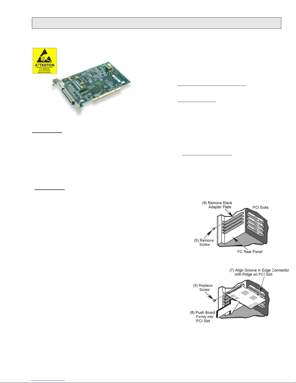
5. Remove the screw that secures the blank adapter plate, which is associated
with the PCI slot you will be using.
6. Remove the blank adapter plate.
7. Align the groove in the board’s PCI edge-connector with the ridge of the
desired PCI slot, and with the PC’s corresponding rear-panel slot.
8. Push the board firmly into the PCI slot. The board will snap into
position.
9. Secure the board by inserting the rear-panel adapter-plate screw.
10. Using the previous steps, install additional boards into available PCI bus-
slots, if applicable to your application.
11. Replace the computer’s cover.
12. Plug in all cords and cables that were removed in step 1.
13. Apply power to, and start up the PC.
1033-0940, rev 9.0 324324B-01 Printed in Hungary
Page 2

Step 3 – Configure Boards
1. Run the Daq Configuration control panel applet. Navigation from the desktop to the applet is as follows:
Start ⇒ Settings ⇒ Control Panel ⇒ DaqConfiguration (double-click).
2. Double-click on the Device Inventory’s DaqBoard icon (1K0, 2K0, or 3K0, as applicable).
ONLY IF the board’s icon is not present, perform A, B, and C, otherwise go directly to step 3.
(A) After accessing the Daq Configuration control panel applet, click on the <Add Device> button.
(B) Using the Device Type’s pull-down list, select the applicable board.
(C) Click the <OK> button. The board’s Properties tab will appear. At this point, complete steps 3 through 5.
3. Enter a “Device Name” in the text box, or use the default, e.g., DaqBoard2K0. The Name is for identifying the
specific DaqBoard, but actually refers to the PCI slot.
4. Verify that the “Device Type” shows the correct board, e.g., “DaqBoard/1000, DaqBoard/2001, etc.”
Note that available device types can be viewed via the pull-down list.
5. Confirm that the DaqBoard’s text box shows a Bus #, Slot #, and Serial Number. If this text box is empty, use its
pull-down list and select the serial number that matches the one for your board.
Step 4 – Test Hardware
Use the following steps to test the DaqBoard. Note that these steps are continued from those listed under the previous
section, “Configure Boards.”
1. Select the “Test Hardware” tab.
2. Click the “Resource Test” button.
3. After the test is complete, click “OK.” System capability is now tested; and test results are displayed.
Note: If you experience difficulties, please consult your user documentation (included on your CD) before calling for
technical support.
Step 5 – Connect Signals
For /1000 Series and /3000 Series boards, connection is typically made via a terminal board, such as the optional TB-100,
a DBK215 module via a 68-pin SCSI connector and/or or a PDQ30 via a HDMI connector. Note that the DaqBoard/3006
has no HDMI connector and cannot be connected to a PDQ30. The user’s manual, included on the Data Acquisition CD
and also available on our website, contains detailed information, including specifications, pinouts, and numerous
illustrations.
Note that
information regarding the DBK200 Series, refer to the DBK Option Cards and Modules User’s Manual (p/n 457-0905).
A copy is included on the Data Acquisition CD and on our website.
/2000 Series boards typically make use of a DBK200 Series option for connecting signals. For detailed
Reference Notes:
During software installation, Adobe PDF versions of user manuals are automatically installed onto your hard
drive as a part of product support. The default location is in the Programs group, which can be accessed
from the Windows Desktop. The documents can also be read directly from the CD. You will need Adobe
Acrobat or the Acrobat Reader.
*324324B-01*
IOtech, 25971 Cannon Rd., Cleveland, OH 44146-1833
phone: (440) 439-4091; e-mail: productsupport@iotech.com; www.iotech.com
324324B-01
Printed in Hungary
 Loading...