

Page 1
USER’S MANUAL
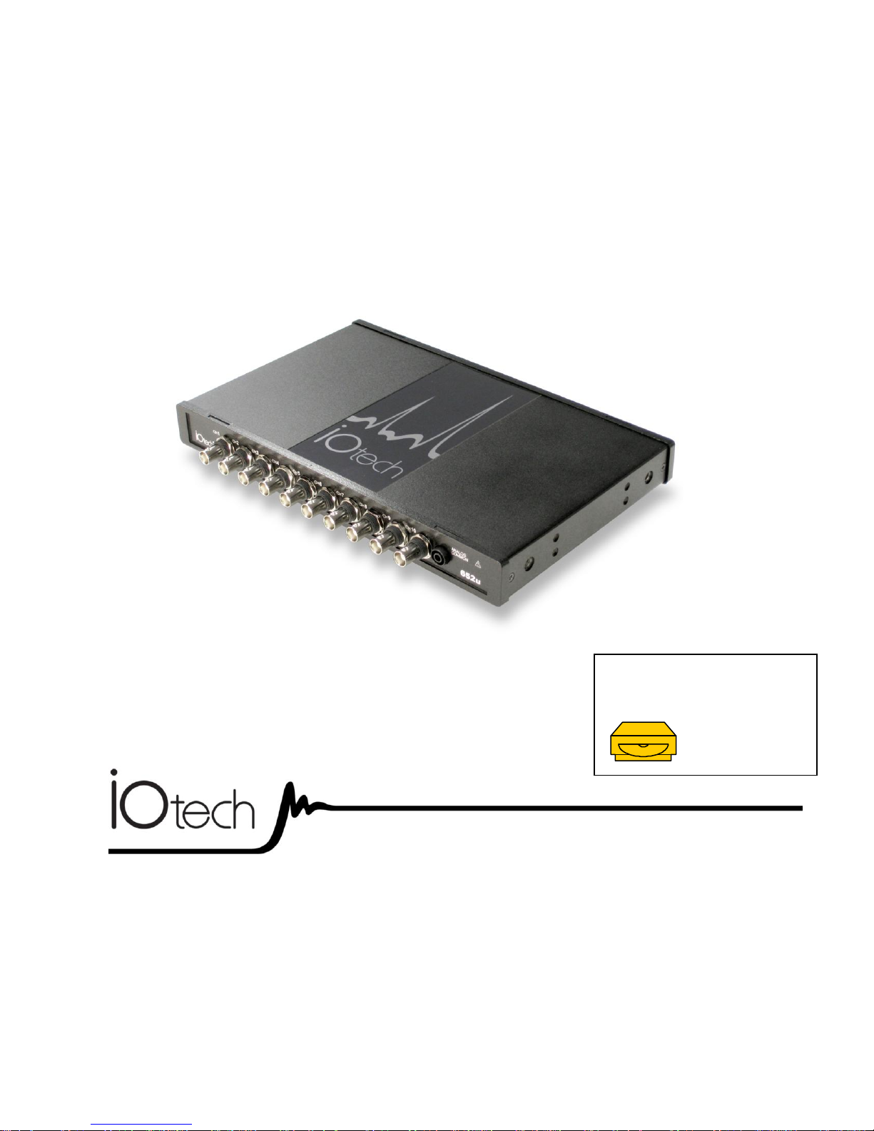
IOtech 652u
1170-0901 rev 1.0
IOtech
25971 Cannon Road
Cleveland, OH 44146-1833
(440) 439-4091
Fax: (440) 439-4093
sales@iotech.com
productsupport@iotech.com
www.iotech.com
*372562A-01*
372562A-01
Requires one of the following
Operating Systems:
Windows 2000 SP4
Windows XP
Windows Vista
IOtech 652u
10 Channel Dynamic Signal Analyzer for
Vibration Analysis and Monitoring
Page 2
Warranty Information
Your IOtech warranty is as stated on the product warranty card. You may contact IOtech by phone,
fax machine, or e-mail in regard to warranty-related issues.
Phone: (440) 439-4091, fax: (440) 439-4093, e-mail: sales@iotech.com
Many IOtech products carry the CE marker indicating they comply with the safety and emissions standards of the
European Community. As applicable, we ship these products with a Declaration of Conformity stating which
specifications and operating conditions apply.
Refer all service to qualified personnel. This caution symbol warns of possible personal injury or equipment damage
under noted conditions. Follow all safety standards of professional practice and the recommendations in this manual.
Using this equipment in ways other than described in this manual can present serious safety hazards or cause equipment
damage.
This warning symbol is used in this manual or on the equipment to warn of possible injury or death from electrical
shock under noted conditions.
This ESD caution symbol urges proper handling of equipment or components sensitive to damage from electrostatic
discharge. Proper handling guidelines include the use of grounded anti-static mats and wrist straps, ESD-protective
bags and cartons, and related procedures.
This symbol indicates the message is important, but is not of a Warning or Caution category. These notes can be of
great benefit to the user, and should be read.
In this manual, the book symbol always precedes the words “Reference Note.” This type of note identifies the location
of additional information that may prove helpful. References may be made to other chapters or other documentation.
Tips provide advice that may save time during a procedure, or help to clarify an issue. Tips may include additional
reference.
Limitation of Liability
IOtech, Inc. cannot be held liable for any damages resulting from the use or misuse of this product.
Copyright, Trademark, and Licensing Notice
All IOtech documentation, software, and hardware are copyright with all rights reserved. No part of this product may be
copied, reproduced or transmitted by any mechanical, photographic, electronic, or other method without IOtech’s prior
written consent. IOtech product names are trademarked; other product names, as applicable, are trademarks of their
respective holders. All supplied IOtech software (including miscellaneous support files, drivers, and sample programs)
may only be used on one installation. You may make archival backup copies.
CE Notice
Warnings, Cautions, Notes, and Tips
Specifications and Calibration
Specifications are subject to change without notice. Significant changes will be addressed in an addendum or revision to
the manual. As applicable, IOtech calibrates its hardware to published specifications. Periodic hardware calibration is
not covered under the warranty and must be performed by qualified personnel as specified in this manual. Improper
calibration procedures may void the warranty.
Page 3

Table of Contents
F
Quick Start
Chapter 1 – What is the IOtech 652u?
Chapter 2 – Block Diagram
Chapter 3 – Connectors, Indicators, and Cables
Front Panel (Analog) Connectors …… 3-1
Introduction …. 3-1
Analog Common …… 3-1
Current Source (IEPE) with Transducer Fault Detection ……. 3-1
Input Coupling …… 3-2
Anti-Aliasing …… 3-2
Analog Triggers …… 3-2
Rear Pannel Connectors and Indicators …… 3-2
External Power ……3-3
Digital I/O (requires eZ-TOMAS)…… 3-3
#6-32 Machine Screw (chassis to earth ground)…… 3-4
USB2.0 …… 3-4
LED Indicators …… 3-4
Chapter 4 – CE Compliance and Noise Considerations
Overview …… 4-1
CE Standards and Directives …… 4-1
Safety Conditions ……4-2
Emissions/Immunity Conditions …… 4-3
CE Rules of Thumb for 652u …… 4-3
Noise Considerations …… 4-4
Chapter 5 – Software Options for 600 Series Devices
eZ-Analyst …… 5-2
eZ-TOMAS …… 5-3
eZ-Balance …… 5-4
eZ-NDT …… 5-5*
Chapter 6 – Product Care and Customer Support
Electrostatic Discharge (ESD), Handling Notice…… 6-1
Product Care …… 6-1
ReadMe Files and the Install CD-ROM …… 6-2
Customer Support …… 6-2
Chapter 7.a – Specifications, IOtech 652u Series
7.b – Specifications, Data Plots
Appendix A – Changing the Device Name
*eZ-NDT does not support IOtech 652u.
IOtech 652u User’s Manual 956991 i
Page 4

This page is intentionally blank.
ii 956991 IOtech 652u User’s Manual
Page 5
IOtech 652u Quick Start
Before you get started
verify that you have the following items and meet or exceed the
minimum requirements listed.
IOtech 652u
TR-2U Power Supply
USB2.0 port [on PC] and USB Cable
Dynamic Signal Analysis CD
License Keys for purchased software;
e.g., eZ-Analyst, eZ-TOMAS
Monitor: SVGA, 1024 x 768 screen resolution
Windows 2000 SP4 and Windows XP users:
Intel
™
Pentium [or equivalent], 1 GHz
512 MB memory; 10 GB disk space
Windows Vista users:
PC must be Windows Vista Premium Ready
Step 1 - Install Software
1. Close all running applications on the host PC.
2. Insert the Dynamic Signal Analysis CD into your CD-ROM drive and wait for the CD to auto-run. An Opening
Screen will appear. As an alternative, you can download software from: www.iotech.com/ftp.html
3. Click the <ENTER SETUP> button.
Note: If you are downloading software from our website, follow instructions provided there.
4. From the hardware selection screen [which follows a licensing agreement], select the 652u
from the drop-down list and follow the on-screen instructions.
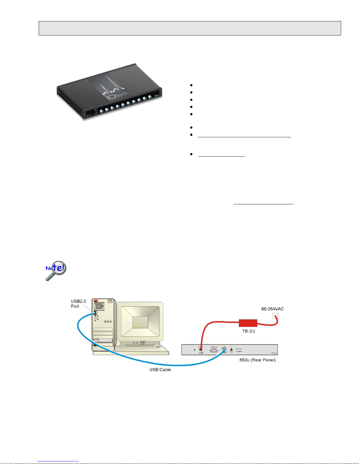
Supply power from the TR-2U to the 652u before connecting the USB cable to the computer. This allows the
652u to inform the host computer (upon connection of the USB cable) that the unit requires minimal power
from the computer’s USB port. When disconnecting a 652u from the PC, unplug the USB cable before
unplugging the TR-2U power cable.
10-Channel, USB2.0 Dynamic Signal Analyzer for Vibration Analysis & Monitoring
Step 2 - Connect the 652u to Power and to the Computer
1. Connect the TR-2U to a standard AC outlet.
2. Connect the TR-2U to the External Power connector on the 652u.
3. Using a USB cable, connect the 652u to a USB2.0 port on the computer. USB2.0 port is required.
4. Follow the computer screen prompts as directed to allow the computer to detect your new hardware.
1170-0940 rev 1.0 324996A-01
Page 6
IOtech
25971 Cannon Road
Cleveland, OH 44146-1833
Phone: (440) 439-4091
Fax: (440) 439-4093
E-mail: sales@iotech.com
E-mail: productsupport@iotech.com
Internet: www.iotech.com
LED Notes: The “Power” LED blinks during device detection and initialization; then remains on solid as long as
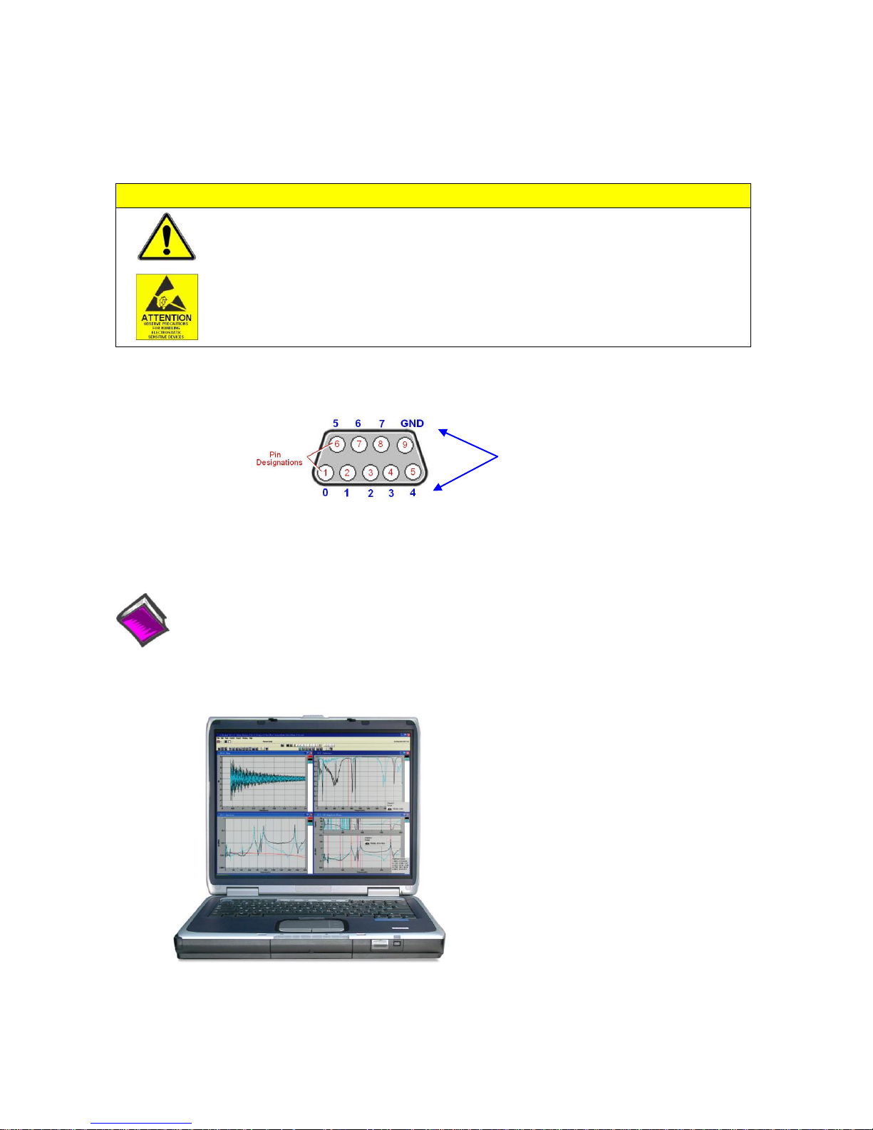
CAUTION
Turn off power to the system devices and externally connected equipment before
connecting cables. Electric shock or damage to equipment can result even under
low-voltage conditions.
Take ESD precautions (packaging, proper handling, grounded wrist strap, etc.)
Reference Notes:
Adobe Acrobat PDF versions of documents pertaining to IOtech 652u are automatically installed onto
your PC’s hard-drive as a part of product support at the time of software installation. The default
location is the Programs group. It can be accessed via the Windows Desktop Start Menu.
*324996A-01*
324996A-01
Digital I/O
Channel
Designation
the module has power. If there is insufficient power the LED will go off. The “Active” LED is on whenever active
communication is taking place between 652u and the host PC. It will be on solid during data acquisitions.
Step 3 - Connect Data Acquisition Signal Lines
The 652u has 10 analog channel inputs (CH1 through CH10) via front panel BNC connectors and 8 digital I/O
lines via rear panel DB9 connector.
Prior to making signal connections review the Specifications chapter of your user’s manual to ensure that the input
signals do not exceed the specified limits. The manual is included in PDF format on the CD.
Printed in Hungary
Page 7
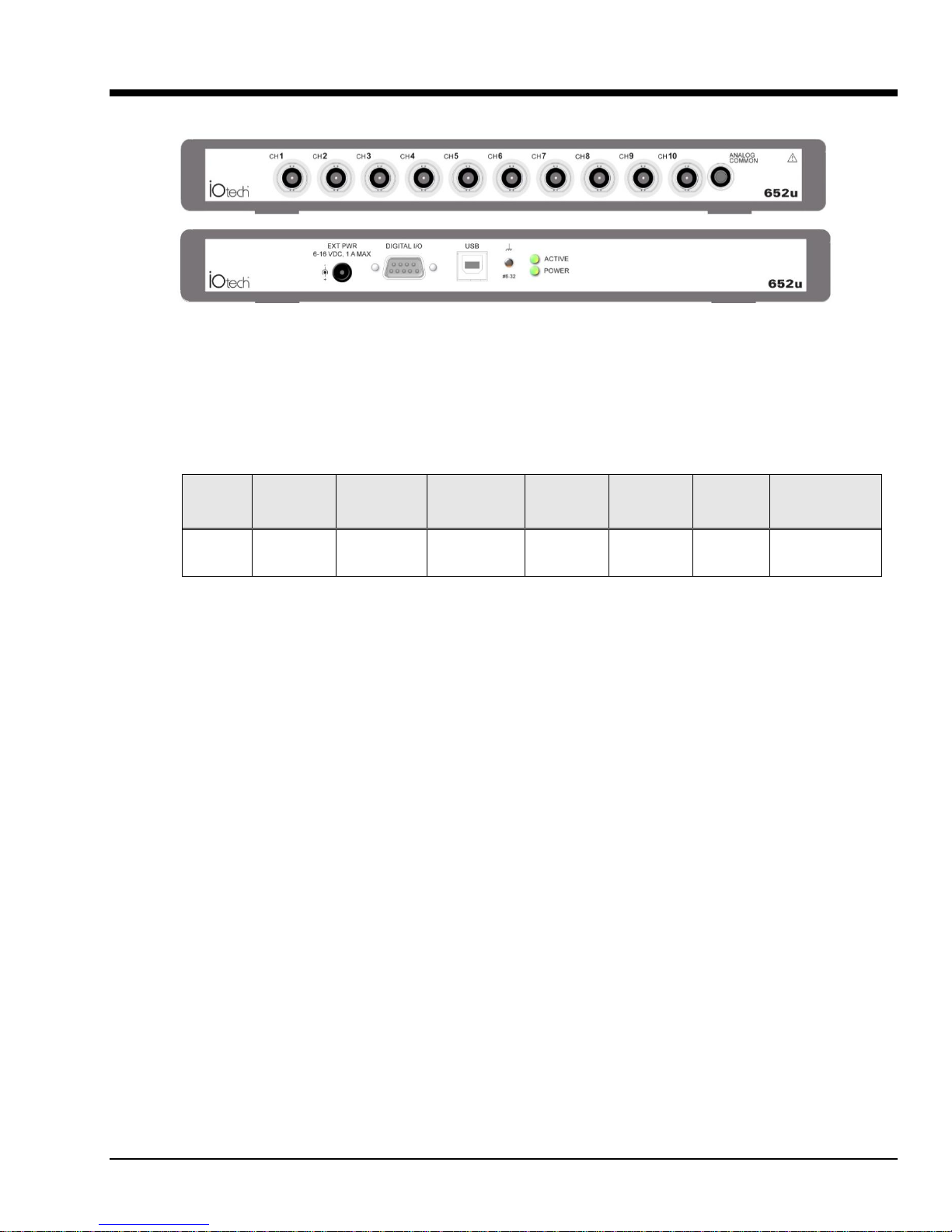
What is the IOtech 652u? 1
Model
Interface
Analog
Input
Channels
High Pass
Filter
Cutoff
Analog
Input
Range
Analog
Output
Channels
Digital I/O
Channels
External Power
Connector
652u
USB2.0
10
0.1 Hz
±40 V 0 8
6 to 16 VDC
1 amp (max.)
eZ-Analyst
Records and analyzes time history data and performs impact (resonance) testing.
eZ-Balance
Provides a solution for multi-plane field balance applications of rotating machinery. The
application computes the optimal balance weights and their locations based on vibration
data collected from the analyzer.
eZ-TOMAS
Acquires, monitors, and analyzes rotating machinery data for steady-state and transient
conditions.
eZ-TOMAS Remote
An optional add-on which allows you to remotely monitor and/or control operation of
eZ-TOMAS. The option is sold separate.
IOtech 652u Front and Rear Panels
IOtech 652u is a dynamic signal analyzer used for monitoring and analyzing machinery and structures in regard to
sound, vibration, and rotation. The device hardware is the signal conditioning and acquisition engine, while the
software defines the specific analysis and monitoring features of the system. Since the software [in the host PC]
determines which capabilities will be used, it is easy to upgrade the system and add more capabilities over time.
Basic profile:
There are currently four end-user software application packages available for IOtech 652u. A brief description of
each follows. For more information refer to Chapter 5, Software Options. For detailed information refer to the
specific software user’s manual. The DSA CD includes PDF versions of the software documents.
The IOtech 652u includes a high-speed USB2.0 engine. The USB interface allows all acquired data to be
transferred to the PC in real time at 1.05 Meg samples/sec. This means that every acquired data point can reside on
the host PC’s hard drive, making re-creation and post acquisition analysis of acquired data as precise as possible.
Many other analyzers simply store frequency-domain information, which results in play-back that is less precise
than the original real-time measurement. In comparison, the 652u (and also our 640 and 650 models) transmit all
time-domain measurements. This means there is no data loss when analyzing acquired waveforms. Since the data
is already on the host PC’s hard drive there is no time lost transferring data.
Another advantage of the 652u architecture is that there is virtually no limit to the length of time continuous data
can be acquired. Many other systems do not offer continuous time-domain transfer to the PC, and as a result the
waveform length is limited by the amount of built-in data storage. In regard to our 652u, the only limitation is the
amount of available hard disk memory on the host PC, or that which can be accessed by a PC on a network.
IOtech 652u User’s Manual 938791 What is the IOtech 652u? 1-1
Page 8

Features of the Dynamic Signal Inputs
o a current source for transducer biasing (IEPE)
o detection of a transducer fault
o AC coupling: 0.1 Hz; or DC coupling
o ±40 V range
o anti-aliasing filters: 3-pole low pass filter in hardware;
software FIR filters are automatically set for each analysis rate
o pseudo-differential inputs
o support for TEDS (Transducer Electronic Data Sheet) in eZ-Analyst
o any analog input channel can serve as a tach input
o tight channel-to-channel phase matching
USB2.0 ready - Easy Connection to USB2.0-ready Notebooks, Desktop PCs, or USB2.0 Hubs.
Note that the USB2.0 port allows a continuous stream of data to be collected and stored in the host PC.
Analog Input Channels: 10 BNC connectors
8 Digital I/O Channels: DB9 connector for connection of Digital I/O signal lines.
Note: eZ-NDT or eZ-TOMAS software must be used to make use of the Digital I/O.
Analog Channel Triggering
Pre- and Post-Trigger Readings
1-2 What is the IOtech 652u? 938791 IOtech 652u User’s Manual
Page 9
Block Diagram 2
IOtech 652u User’s Manual 948491 Block Diagram 2-1
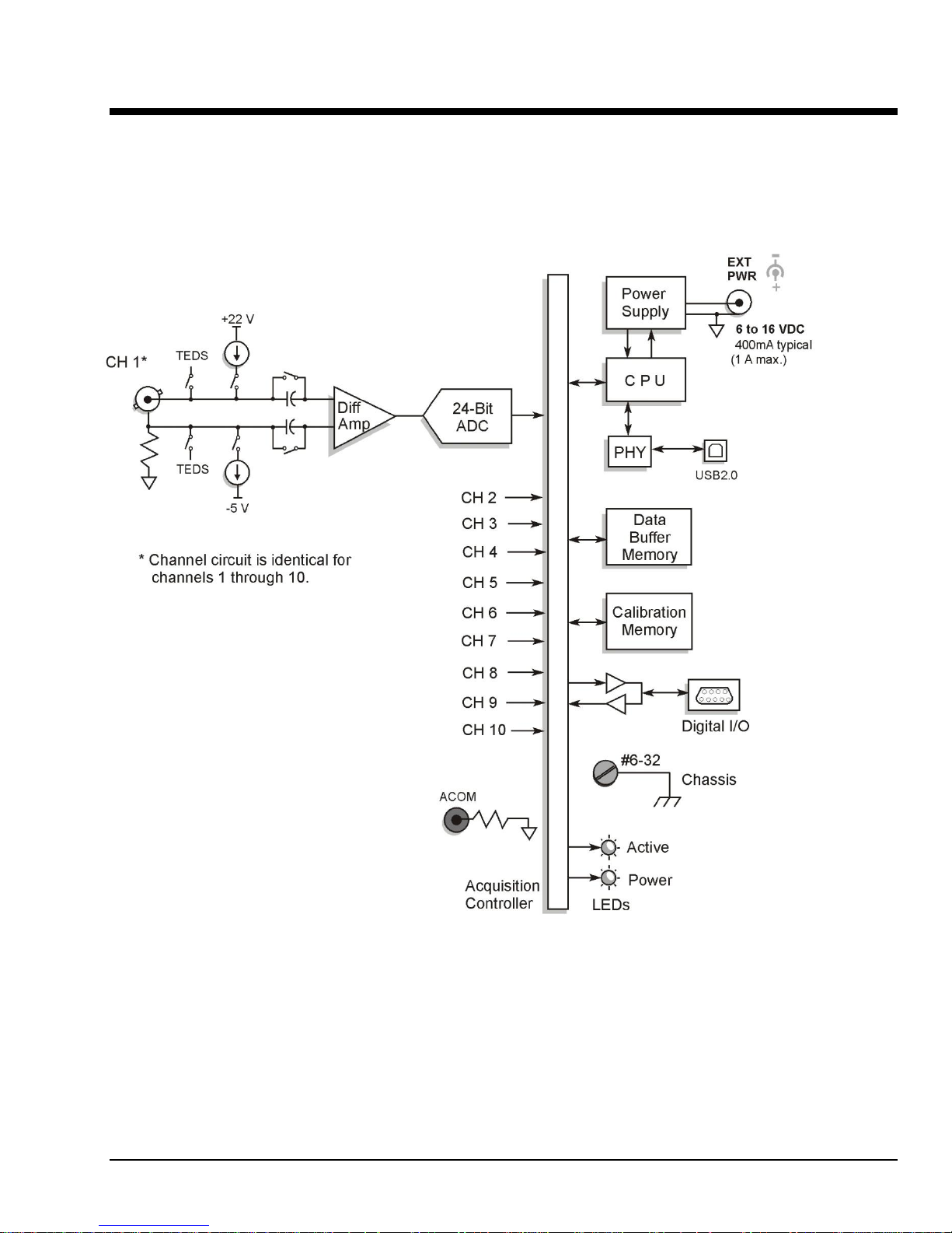
IOtech 652u Block Diagram
Page 10

USB2.0
The IOtech 652u transfers acquired data to the PC via a USB2.0 connection. It is important to note that
USB ports and USB hubs cannot supply sufficient power to a 652u.
Power
Power (6 to 16VDC at 400mA) is typically supplied by a TR-2U power adapter connected to the External
Power Jack. An equivalent source of DC power can be used in place of a TR-2U.
LEDs
Active
The Active LED is on whenever active communication is taking place between the 652u and
the host PC. Note that the Active LED will be on solid during a data acquisition.
Power
The “Power” LED blinks during device detection and initialization; then remains on solid
as long as the module has power. If there is insufficient power the LED will go off.
Digital
I/O
To make use of the Digital I/O feature the 652u must be operating with eZ-TOMAS or eZ-NDT.
The 8-bits of digital I/O are provided via a rear panel DB9 connector. Each bit is programmable as
input or output.
BNCs
Up to ten BNC connectors, designated as Channels 1 through 10, can be used to connect analog input
signals to the 652u. The BNC center-conductor is the signal HI and the BNC shell is the signal LO.
General Comments
The following short descriptions are provided to supplement the preceding block diagram. For additional information
refer to Chapter 3, Connectors, Indicators, and Cables.
2-2 Block Diagram 948491 IOtech 652u User’s Manual
Page 11
Connectors, Indicators, and Cables 3
Front Panel (Analog) Connectors …… 3-1
Introduction …. 3-1
Analog Common …… 3-1
Current Source (IEPE) with Transducer Fault Detection ……. 3-1
Input Coupling …… 3-2
Anti-Aliasing …… 3-2
Analog Triggers …… 3-2
Rear Pannel Connectors and Indicators …… 3-3
External Power ……3-3
Digital I/O (requires eZ-TOMAS)…… 3-3
#6-32 Machine Screw (chassis to earth ground)…… 3-4
USB2.0 …… 3-4
LED Indicators …… 3-4
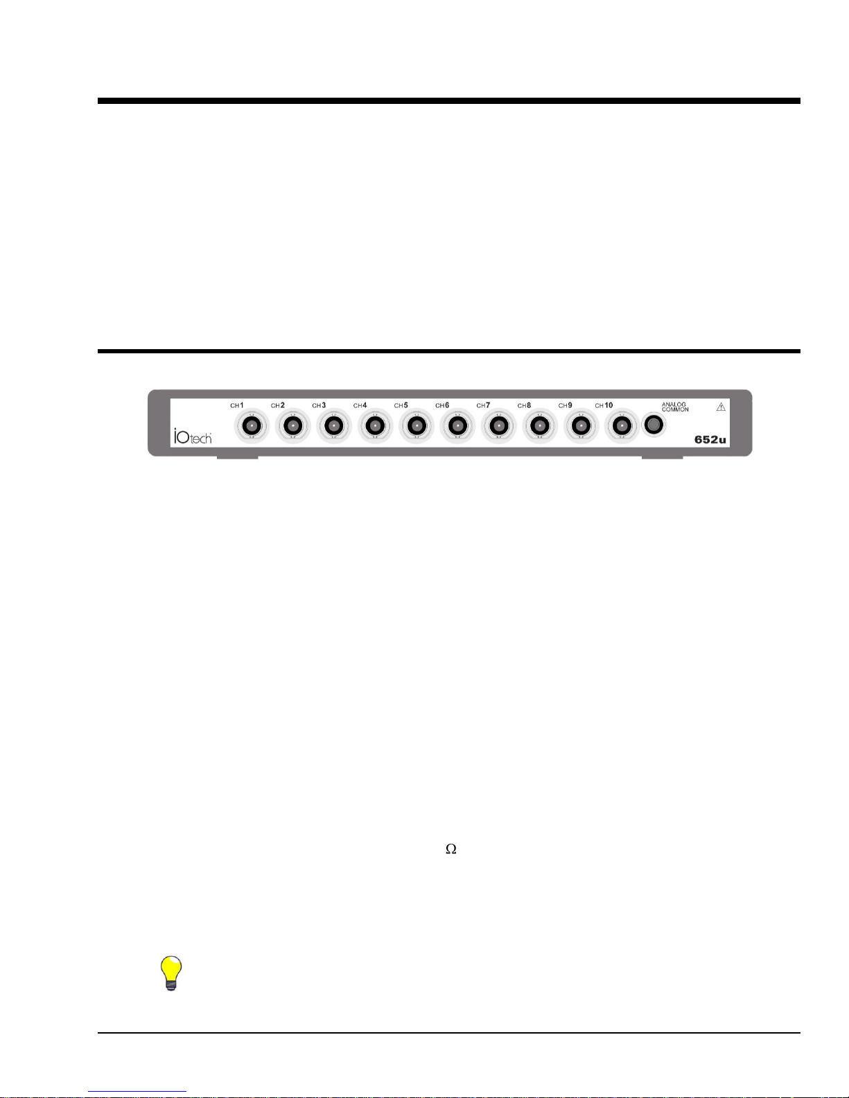
The front panel includes ten BNC connectors for voltage input. These are labeled CH1 through CH10. The front
panel also includes analog common. The IOtech 652u includes circuitry for dynamic analog signal conditioning.
The circuitry typically interfaces with piezoelectric transducers that include, but are not limited to: accelerometers,
microphones, tachometers, and force/pressure transducers.
TIP: Additional measurement noise may be present when using earth grounded transducers.
For best results electrically isolate the input transducers from earth ground.
Front Panel (Analog) Connectors
652u Front Panel
Introduction
Features of the 652u’s dynamic signal conditioning circuit include:
o current source for transducer biasing (IEPE)
o detection of a transducer fault
o AC or DC coupling
o ±40 V range
o anti-aliasing filters: 3-pole low pass filter in hardware; programmable digital filtering via software
o pseudo-differential inputs
o support for TEDS (Transducer Electronic Data Sheet), requires eZ-Analyst
o any analog input channel can serve as a tach input
o channel-to-channel phase matching
o signal parameters are independently controlled in software on a per channel basis
Analog Common
The BNC shells for the analog input channels have a 1k ohm resistance from the BNC shell to analog ground. The
BNC center-conductor is the signal HI and the BNC shell is the signal LO. Each BNC shell is connected to the
chassis ground through its own channel-dedicated 1 k resistor. Consequently, the shell is not meant to be driven
with respect to earth ground more than ±10V.
If the host computer is a desktop PC, then the computer ground will likely connect to the AC power line ground.
If the host computer is a notebook PC, then the computer ground could be: (a) floating, for example, when operating
on batteries, or (b) connected to a vehicle ground, for example, when using an automotive cigarette lighter adapter in
conjunction with the vehicle’s battery.
652u User’s Manual 957091 Connectors, Indicators, and Cables 3-1
Page 12

Current Source (IEPE) with Transducer Fault Detection
Reference Notes:
For detailed information, refer to the applicable software document, i.e., eZ-TOMAS or eZ-Analyst.
PDF versions of the documents can be accessed via the <View PDFs> button on the Dynamic Signal
Analysis (DSA) CD’s opening screen.
In addition to software documentation, information regarding aliasing, anti-aliasing, sensors,
accelerometers, sound and vibration, and transducers may prove useful to your application. The
internet is a great source for this material.
In regard to TEDS (Transducer Electronic Data Sheet), you may find the IEEE 1451 standard to be of
interest.
Note: IEPE current source can only be enabled when AC Coupling is selected.
If IEPE is selected in software, a constant current is supplied to bias IEPE transducers. The bias current is sourced
through the center conductor of the input channel BNC connector and returns to the conditioning circuit by the outer
conductor. The current source features a voltage operating compliance and is short-circuit and over-voltage
protected as stated in the specifications. Operating compliance refers to the highest voltage that can be sourced
without change of the current source value. In the absence of a transducer, the current source will output a higher
open circuit voltage. For unused channels and for other applications that do not require bias, the current
source should be disabled from the input via software control, on a per channel basis.
When the current source is enabled, the input voltage is continuously monitored with level detection circuitry for
indicating an open transducer (high voltage) or a transducer short (low voltage). Existence of either condition
triggers a transducer fault for the associated channel. This error is communicated to the user on the monitor via
software and is also available through a software status request at the end of an acquisition. Faults are detected and
communicated when present. Detection of a fault does not alter the acquisition process or its data.
Input Coupling
The analog input channels can be independently set in software to AC Coupling or to DC Coupling. When AC
Coupling is selected, the input signal passes through a high pass filter. When DC Coupling is selected the high-pass
filter is bypassed.
Anti-Aliasing
The 652u analyzer includes three-pole anti-aliasing filters and 24-bit sigma/delta analog-to-digital converters (ADC).
The converters exhibit an alias frequency band between 1.69MHz and 6.75MHz, which eases the requirements of the
anti-aliasing filters. Transducers seldom have significant energy at these high frequencies. However, should there
happen to be such energy, the filters will attenuate it. Refer to the specifications chapter for details, including a
response chart.
Analog Triggers
The IOtech 652u signal analyzer can be triggered per software configuration relevant to the 10 analog input
channels. Refer to the associated software documentation regarding the various types of triggers and how to set
them.
3-2 Connectors, Indicators, and Cables 957091 652u Users Manual
Page 13

Digital I/O Connector
DB9 –on rear panel
Digital I/O
Channel
Numbers
Rear Panel Connectors and Indicators
IOtech 652u Rear Panel, Partial View
The rear panel includes, from left to right: an External Power connector, DB9-Digital I/O port, USB2.0 connector, a #6-32
chassis ground, and two status LEDs (ACTIVE and POWER).
EXT POWER: +6 to +16 VDC, 1 amp (maximum). Power is typically supplied from a TR-2U power adapter.
The TR-2U is an AC-to-DC conversion power supply with the following ratings:
o Input voltage to TR-2U: 90-264 VAC
o TR-2U voltage output (supply to 652u): typically 9VDC
o Max Current Output: 1.7 amp; but will typically output 400mA to meet
the 652u’s relatively small power demand.
DIGITAL I/O (Note: requires eZ-TOMAS installed on the host PC)
Eight digital I/O lines are accessible via a 9-pin, female DSub connector. Each bit of digital I/O can be programmed
individually to be either an input or an output. By hardware default, the digital I/O port boots up as an input. This is
to prevent any 652u digital output from possibly damaging external hardware.
The digital I/O can be read synchronously or asynchronously. It can also be read asynchronously while being in a
synchronous acquisition. Synchronously, the digital I/O will be read at the same rate as the analog channels, and
thus can be read as fast as 105.469 kHz. Since all of the analog signals are read simultaneously along with the digital
I/O channel in synchronous mode, there is no delay between any analog signal and the digital I/O channel.
Asynchronously, the digital I/O can be either read or written to, as opposed to the synchronous mode, which is readonly.
Points to note:
To use the 652u’s Digital I/O, the host PC must have eZ-TOMAS software installed.
All configurations pertaining to Digital I/O are controlled by software and can be updated by the
software at any time.
All 8 digital inputs can be read back as part of the scan group of an acquisition.
652u User’s Manual 957091 Connectors, Indicators, and Cables 3-3
Page 14

Reference Note:
eZ-TOMAS User’s Manual. A PDF version is included on the DSA CD.
#6-32 machine screw (chassis to earth ground):
The machine screw on the rear panel is used to connect the chassis to solid earth ground.
USB2.0: This port is intended for USB2.0 high-speed (480Mbps). In regard to 652u, connection to a USB2.0 port on the
host PC is required. The use of a High-Speed USB Cable is recommended. IOtech cable part numbers CA-179-1, -3, and -
5 are 1m, 3m, and 5m in length, respectively.
The IOtech 652u transfers acquired data to the PC via USB. When a computer has a board with USB 2.0 ports, an
“Enhanced” USB controller can be found in the Device Manager. The Device Manager will also show two other USB
controllers due to the fact that USB2.0 circuitry includes 3 chips [one for the actual USB2.0 capable devices and two for
backward USB1.1 compatibility]. Thus a USB 2.0 motherboard can host any USB device (version 2.0 or lower), assuming
there are no defects with the board, system, and/or device.
o IOtech 652u requires connection to USB2.0
o USB 1.1 (obsolete) hubs will work on USB 2.0 ports, but cannot utilize USB 2.0 capabilities.
o Hi-Speed and Full/Low-Speed USB devices can coexist on USB 2.0 hubs.
o USB 2.0 hubs can be used on computers with USB 1.1 ports, but will not exhibit USB 2.0 capabilities.
o Minimize hub use and keep USB cables as short as possible.
o USB ports and USB hubs cannot supply sufficient power to a 652u.
LED Indicators
ACTIVE This indicator is on whenever active communication is taking place between the 652u and
the host PC. Note that the ACTIVE LED is on solid during data acquisitions.
POWER This indicator blinks during device detection and initialization; and then remains on solid, as long
as there is sufficient power. If there is insufficient power the POWER LED will go off.
3-4 Connectors, Indicators, and Cables 957091 652u Users Manual
Page 15

CE Compliance & Noise Considerations 4
Overview ……4-1
CE Standards and Directives …… 4-1
Safety Conditions ……4-2
Emissions/Immunity Conditions ……4-3
CE Rules of Thumb for 652u …… 4-3
Noise Considerations …… 4-4
CE compliant products bear the “CE” mark and include a Declaration of Conformity stating the
particular specifications and conditions that apply. The test records and supporting documentation
that validate the compliance are kept on file at the factory.
Overview
The European Union established CE standards in 1985. The standards include specifications for safety,
EMI emissions, and immunity from electromagnetic interference. Products that are intended for placement
in the European Union must meet or exceed the standards and bear the “CE” mark.
Although not required in the USA, meeting or exceeding the CE standards is considered good engineering
practice, since doing so enhances safety while reducing noise and ESD problems.
In contracted and in-house testing most acquisition products met the required specifications. In many cases
products that were not originally in compliance were redesigned accordingly. In noted instances alternate
product versions, shield plates, edge guards, special connectors, or add-on kits are required to meet CE
compliance.
CE Standards and Directives
The electromagnetic compatibility (EMC) directives specify two basic requirements:
1. The device must not interfere with radio or telecommunications.
2. The device must be immune from electromagnetic interference from RF transmitters, etc.
The standards are published in the Official Journal of European Union under direction of CENELEC
(European Committee for Electrotechnical Standardization). The specific standards relevant to data
acquisition equipment are listed on the product’s Declaration of Conformity.
The safety standard that applies to data acquisition products is EN 61010-1 : 1993 (Safety Requirements
for Electrical Equipment for Measurement, Control, and Laboratory Use, Part 1: General Requirements).
Environmental conditions include the following:
indoor use
altitude up to 2000 m
temperature 5°C to 40°C (41°F to 104°F)
maximum relative humidity 80% for temperatures up to 31°C (87.8°F) decreasing linearly
to 50% relative humidity at 40°C (104°F)
mains supply voltage fluctuations not to exceed ±10% of the nominal voltage
other supply voltage fluctuations as stated by the manufacturer
transient overvoltage according to installation categories (overvoltage categories) I, II and III
For mains supply, the minimum and normal category is II
652u User’s Manual 957791 CE-Compliance & Noise Considerations 4-1
pollution degree I or II in accordance with IEC 664
Page 16

For clarification, terms used in some Declarations of Conformity include:
This WARNING symbol is used in documentation and/or on hardware to warn of
possible injury or death from electrical shock under noted conditions.
This WARNING/CAUTION symbol is used to warn of possible personal injury or
equipment damage under noted conditions.
This CAUTION symbol warns of possible equipment damage due to electrostatic
discharge. The discharge of static electricity can damage some electronic
components. Semiconductor devices are especially susceptible to ESD damage. You
should always handle components carefully, and you should never touch connector
pins or circuit components unless you are following ESD guidelines in an appropriate
ESD-controlled area. Such guidelines include the use of properly grounded mats and
wrist straps, ESD bags and cartons, and related procedures.
Unless otherwise stated our data acquisition products contain no user-serviceable
parts. Only qualified personnel are to provide service to the devices.
pollution degree: any addition of foreign matter, solid, liquid or gaseous (ionized gases) that may
produce a reduction of dielectric strength or surface resistivity. Pollution Degree I has no influence
on safety and implies: the equipment is at operating temperature with non-condensing humidity
conditions; no conductive particles are permitted in the atmosphere; warm-up time is sufficient to
avert any condensation or frost; no hazardous voltages are applied until completion of the warm-up
period. Pollution Degree II implies the expectation of occasional condensation.
overvoltage (installation) category: classification with limits for transient overvoltage, dependent
on the nominal line voltage to earth. Category I implies signals without high transient values.
Category II applies to typical mains power lines with some transients.
Safety Conditions
Users must comply with all relevant safety conditions as stated in the user’s manual and in the pertinent
Declarations of Conformity. Both the documentation and the associated hardware make use of the
following Warning and Caution symbols. If you see any of these symbols on a product or in a document,
carefully read the related information and be alert to the possibility of personal injury and/or equipment
damage.
The specific safety conditions for CE compliance vary by product; but general safety conditions include the
following bulleted items:
The operator must observe all safety cautions and operating conditions specified in the
documentation for all hardware used.
The host computer and all connected equipment must be CE compliant.
All power must be off to the device and externally connected equipment before internal access to the
device is permitted.
Isolation voltage ratings: do not exceed documented voltage limits for power and signal inputs.
All wire insulation and terminal blocks in the system must be rated for the isolation voltage in use.
Voltages above 30 Vrms or ±60 VDC must not be applied if any condensation has formed on the
device.
Current and power use must not exceed specifications. Do not defeat fuses or other over-current
protection.
4-2 CE-Compliance & Noise Considerations 957791 652u User’s Manual
Page 17

Emissions/Immunity Conditions
The specific immunity conditions for CE compliance vary by product; but general immunity conditions
include:
Cables must be shielded, braid-type with metal-shelled connectors. Input terminal connections are to
be made with shielded wire. The shield should be connected to the chassis ground with the hardware
provided.
The host computer must be properly grounded.
In low-level analog applications some inaccuracy is to be expected when I/O leads are exposed to
RF fields or transients over 3 or 10 V/m as noted on the Declaration of Conformity.
CE Rules of Thumb for 652u
IOtech 652u units are CE Compliant at the time they leave the factory and should remain in compliance as
long as the conditions stated on the Declaration of Conformity continue to be met.
A few general rules of thumb:
Use short cables.
When possible use shielded cables.
When assembling or disassembling components, take ESD precautions,
including the use of grounded wrist straps.
Ensure that the host computer is CE Compliant.
Review the most recent Declaration of Conformity for the 652u.
Ensure all system components are properly grounded.
652u User’s Manual 957791 CE-Compliance & Noise Considerations 4-3
Page 18

Noise Considerations
Controlling electrical noise is imperative because it can present problems even with the best measurement
equipment. Most laboratory and industrial environments suffer from multiple sources of electrical noise.
For example, AC power lines, heavy equipment (particularly if turned on and off frequently), local radio
stations, and electronic equipment can create noise in a multitude of frequency ranges.
Local radio stations are a source of high frequency noise, while computers and other electronic equipment
can create noise in all frequency ranges. Creating a completely noise-free environment for test and
measurement is seldom practical. Fortunately, simple techniques such as using shielded/twisted pair wires,
filtering, and differential voltage measurement are available for controlling the noise in our measurements.
Some techniques prevent noise from entering the system; other techniques remove noise from the signal.
While many techniques for controlling noise in signals provide a means of removing the noise that is
already present, the preferred solution is to prevent the occurrence of noise in the signal in the first place.
The following practices, some of which are required for CE compliance, should be employed to minimize
noise.
Make a solid earth ground connection. Using insulated low resistance wire, connect the
652u chassis (via the rear panel #6-32 machine screw) to solid earth ground. This practice:
(a) keeps radiated emissions low by keeping the chassis electrically quiet,
(b) keeps potential common-mode voltages low,
(c) improves user safety, and
(d) provides a safe path for Electrostatic Discharge energy back to earth ground.
Use short USB cables. The use of short USB cables will reduce noise. The shorter the cable
the better.
Use shielded cables. Loose wires are effective antennae for radio frequency pickup and can
form loops for inductive pickup. The use of properly connected shields will greatly reduce
such noise.
Minimize ambient EMI. The lower the ambient EMI, the better. Sources of electromagnetic
interference include solenoids, motors, computer equipment, high power distribution wiring,
etc.
Distance cables. Route signal cables away from Ethernet lines, Mains and other high voltage
cables and equipment to minimize signal interference from radiated noise.
4-4 CE-Compliance & Noise Considerations 957791 652u User’s Manual
Page 19

Software Options for 600 Series Devices 5
eZ-Analyst
Real- Time Vibration & Acoustic Analysis Software …… 5-2
eZ-TOMAS
On-line Rotating Machine Monitoring and Analysis Software …… 5-3
eZ-TOMAS Remote*
Remote monitor and control application …… 5-3
eZ- Balance
Rotating Machine, Field Balancing Software …… 5-4
eZ-NDT **
Non-Destructive Test Software …… 5-5
Reference Notes:
For detailed information regarding software, refer to one or more of the following as
applicable.
eZ-Analyst User’s Manual
eZ-TOMAS and eZ-TOMAS Remote User’s Manual
eZ-Balance User’s Manual
eZ-NDT User’s Manual**
A PDF version of each is included on the installation CD and on our website.
This chapter offers a glimpse of the eZ software packages that can be used with an IOtech 600 series device,
with exceptions as noted. The software is usually purchased when the hardware is ordered; but should your
acquisition needs change, additional software packages can be ordered at a later time.
* eZ-TOMAS Remote requires use of a licensed copy of eZ-TOMAS. For eZ-TOMAS Remote to operate,
the version numbers of the two applications (eZ-TOMAS and eZ-TOMAS Remote) must match.
652u User’s Manual 928291 Software Options 5-1
** eZ-NDT does not support IOtech 652u.
Page 20

eZ-Analyst
Real-Time Vibration & Acoustic Analysis Software
eZ-Analyst is the result of more than ten years
of software development and customer input.
This software adds real-time continuous and
transient data acquisition to an IOtech 600
series system. Analysis can be in the time,
frequency, or order domain.
eZ-Analyst is operated through a series of
setup windows that display only the information deemed important to your test. Acquisition configuration involves selecting desired
acquisition parameters from user-friendly
menus.
Features
Real-time FFT analysis
Easy-to-use graphical user interface provides fast setup
Large number of display options: Time Waveform, Spectrum, Auto Spectrum,
FRF, Cross, PSD, Transfer Function, Coherence, Octave, and Waterfall
Order Normalization and Order Tracked Plots
Multiple Plot Overlays using exported data files
Export to Excel, ME Scope, SMS Star, or UFF Type 58 ASCII or Binary
Save/Recall display setups with multiple display windows and overlays
Wide selection of real-time analysis features, including integration/differentiation
averaging, and much more
5-2 Software Options 928291 652u User’s Manual
Page 21

eZ-TOMAS (On-Line Rotating Machine Monitoring & Analysis Software) and
eZ-TOMAS Remote (Remote monitor and control application)
eZ-TOMAS provides an economical means of continuously monitoring and analyzing rotating machinery.
eZ-TOMAS records the change in vibration condition, and
quickly provides information for making important
operational decisions regarding the machine. You can
display and analyze historical data while eZ-TOMAS
continues to collect, monitor, and store data.
An IOtech 600 series system running with eZ-TOMAS can
be easily moved from machine to machine with very short
setup times. You can use the system to reduce downtime,
improve data collection, troubleshoot, and recondition the
machine.
eZ-TOMAS Remote is a software application that allows you
to remotely monitor and/or control eZ-TOMAS applications
through client/server architecture. The server, an eZTOMAS application, interacts with the hardware; and can be
in a remote location. Each client (eZ-TOMAS Remote)
communicates with eZ-TOMAS via TCP/IP.
Features
Transient and Steady State rotating machinery analysis
Easy-to-use graphical user interface and multiple project configurations provide fast setup
Overall, spectral amplitude, and phase gauges with peak hold indicators
Spectral limit checking, with output relays and alarm event logging
Limit sets for specific RPM ranges
Event data storage based on user defined triggers, with automatic backup
Rotating Machinery Analysis: Time Waveform, Orbit, Spectrum, Waterfall, Polar,
Bode, Shaft Center Line, and Trend displays
Machine and Bearing Fault analysis and limit checking
Save/Recall display setups with multiple display windows and overlays
Integration and differentiation for acceleration, velocity, and displacement inputs
Harmonic, Sideband, and Peak cursors for time waveform and spectrum displays
Statistical analysis report with automatic limit generation
Generate production test cell reports
Export data to Excel, UFF Type 58 Binary, or ASCII format
Copy/Paste graphs and data into Microsoft applications
Remotely monitor and/or control eZ-TOMAS with purchase of eZ-TOMAS Remote
652u User’s Manual 928291 Software Options 5-3
Page 22

eZ-Balance
Rotating Machine Balancing
An IOtech 600 series system using eZ-Balance
provides a solution for multi-plane field balance
applications of rotating machinery. eZ-Balance
computes the optimal balance weights and their
locations, based on vibration data collected from the
analyzer. The data is displayed in a convenient
Polar plot that indicates the magnitude and phase of
the unbalance as well as time and spectrum data.
eZ-Balance determines a balance solution by
calculating the change in vibration condition based
on adding trial weights. The balance process is a
series of well defined steps.
Accelerometers, velocity probes, or displacement
probes may be used to measure the vibration level
at each balance plane. A tachometer measures the
rotation speed and provides a phase reference.
Features
Single, Multi-plane, and trim balancing
Polar, time, and spectral displays
Computes and stores influence coefficients for future trim balancing
Vibration data can be acquired from the analyzer or entered manually
Balancing toolkit
- Trial weight calculations
- Weight splitting
- Centrifugal force
- Stock weights
- Weight removed
- Unbalance tolerance
Balance solution can be based on multiple response points
5-4 Software Options 928291 652u User’s Manual
Page 23

eZ-NDT Does not support 652u
Non-Destructive Test Software
eZ-NDT (non-destructive test) uses resonance
to identify part variations caused by process
inconsistencies and defects. Using eZ-NDT with
an IOtech 600 series device is a fast and
inexpensive method for performing 100%
inspection of production parts. Inspection parts
include, but are not limited to: powder metal,
ceramics, and composites.
An eZ-NDT system applies energy to target parts
and analyzes the resonant frequencies. The
system compares the results to the acoustic
signature of a known-good part.
Testing a part takes less than one second and
requires no special tooling, dyes, chemicals,
cleaning, magnetization, or expensive and time
consuming visual inspection equipment.
Features
Provides inspection of metal, ceramic, and hard plastic parts
Removes the ambiguity that is common in other inspection systems
Requires no parts preparation, making the test fast and inexpensive
Tests parts in less than 1 second
Quantifies and documents the first natural frequency for end user
comparison to final assembly resonant frequencies
Time and Spectrum Display
Easy-to-use graphical user interface provides fast setup
Overlay good and bad baselines
Investigation and Inspection Modes
652u User’s Manual 928291 Software Options 5-5
Page 24

This page is intentionally blank.
5-6 Software Options 928291 652u User’s Manual
Page 25

Product Care and Customer Support 6
The discharge of static electricity can damage some electronic components. Semiconductor devices are
especially susceptible to ESD damage. You should always handle components carefully, and you should
never touch connector pins or circuit components unless you are following ESD guidelines in an
appropriate ESD-controlled area. Such guidelines include the use of properly grounded mats and wrist
straps, ESD bags and cartons, and related procedures.
Electrostatic Discharge (ESD) Handling Notice…… 6-1
Product Care …… 6-1
ReadMe Files and the Install CD-ROM ……6-2
Customer Support …… 6-2
Electrostatic Discharge (ESD) Handling Notice
Product Care
IOtech 652u is essentially maintenance free and requires only a minimal amount of care. The 652u should be
treated much like any other high-tech piece of equipment. In general:
The units should be operated in ventilated and relatively dust-free environments.
Keep the units clear of harsh chemicals and abrasive elements.
Avoid exposing the products to extreme heat; for example, avoid setting the units near boilers and
furnaces.
Avoid extreme shock and vibration.
Avoid subjecting the units to liquids and extremely fine air particulate, such as silica dust.
Never open the unit. The unit should only be opened by qualified service technicians.
A “common-sense” approach to handling acquisition components will go a long way in protecting them from
inadvertent damage.
Note that you can use lint-free rags and Isopropyl Alcohol (Rubbing Alcohol) to clean the outer surfaces of the
IOtech 652u.
IOtech 652u User’s Manual 958991 Product Care and Customer Support 6-1
Page 26

ReadMe Files and the Install CD-ROM
The Install CD-ROM includes ReadMe Files. These files often contain late-breaking information that may not
appear in the user documentation. During installation you should review the ReadMe files when prompted to by the
program.
The Install CD-ROM includes:
Windows drivers
eZ-Anlayst*
eZ-TOMAS*
eZ-Balance*
eZ-NDT*
Daq Configuration Control Panel Applet
User documentation in Adobe® PDF format
30-day trial codes for the eZ-software packages
*Requires an authorization code for installation. Authorization codes are supplied with the purchase of the
associated software. Note that the CD does include 30-day trial codes.
Customer Support
If you need to report problems or request product support . . .
Note: Please do not return any equipment to the factory unless it has an RMA number (Return Merchandise
Authorization number). RMA numbers are issued by the factory.
To report problems or request support, contact our Applications Department. Contact information follows shortly.
When you contact us, please have the following information available, as applicable:
Hardware model numbers and software version numbers.
Operating system, type of computer, and device information in the Windows control panel, such as
interrupts and address settings for our hardware and others.
Results of tests, such as the Daq Configuration control panel.
Hardware setup and software configuration.
Information on input signals, including voltage ranges, signal impedance ranges, noise content, and
common mode voltages.
The name of a contact person from your company who can discuss the problems encountered.
Instructions for return shipping.
All troubleshooting notes and comments on tests performed, and all problem-related conditions.
Note: Before calling for assistance, take a few minutes to read all parts of the manual that may be relevant to the
problem. Also, please review the troubleshooting material.
You can reach IOtech by one of the following means:
Phone: (440) 439-4091
Fax: (440) 439-4093
E-mail Product Information/Sales: sales@iotech.com
E-mail Technical Support/Applications Department: productsupport@iotech.com
Internet: www.iotech.com
Mail: IOtech 25971 Cannon Road Cleveland, Ohio 44146-1833
All equipment returned to the manufacturer must have an RMA (Return Material Authorization) number. You can
obtain an RMA number from our Applications Department. When returning the equipment, use the original shipping
container (or equivalent) to prevent damage. Put the RMA number on your shipping label to ensure that your
shipment will be handled properly. After receiving your equipment, we will fax a confirmation form that
summarizes the charges (if applicable) and expected return date.
6-2 Product Care and Customer Support 958991 IOtech 652u User’s Manual
Page 27

Specifications – IOtech 652u 7.a
Section 7.b, Specifications, Data Plots, contains a great deal of information in the form of plotted data. References
to the plots appear in this section (7.a) when applicable.
General Specifications
Environment:
Operating Temperature: -40˚ to 60˚C
Humidity: 0˚ to 95% RH, non-condensing
Vibration: IEC 60068-2-64
Shock: IEC 60068-2-27
Emissions: EN61326, 89/366EEC
Safety: EN61010
Ingress: IP 40
Power Consumption:
<3.5W max
Input Voltage Range:
6.0 to 16 VDC
PC Communication:
USB2.0
Dimensions: 10.9” W x 6.685” D x 1.2”H
(276.9mm W x 169.8mm D x 30.5mm H)
Weight: 2.7 lbs. (1.2 kg)
Warm-up: 10 minutes to rated specifications
Analog Specifications
Analog Measurements
ADC converter resolution: 24 bits
ADC converter type: Delta-sigma
Sample rates: up to 105,468 samples per second
Sample rate accuracy: ±50ppm
Channels: 10 input channels
Input connector: 1 BNC per channel
Input impedance:
High to ground: 800kΩ || 120 pF
Low to ground: 1kΩ
High to low: 801kΩ
Input coupling: DC, AC, or AC + IEPE; software programmable per channel basis
High-pass filter (AC coupling cutoff): 0.1Hz
Figure 1. Measurement High Pass Filter Response
Input range: ±40V peak
Input protection: BNC Shell to BNC Center: ±60V Max without damage
BNC Shell to Earth Ground: ±5V Max without damage
Over-range indication: Software
Low-pass filter (software programmable per channel)
Figure 2. Measurement Delay vs. Frequency, DC-Coupled
Figure 3. Measurement Delay vs. Frequency, AC-Coupled
IOtech 652u User’s Manual 927791 Specifications 7.a-1
Page 28

Specifications are subject to change without notice.
Analysis
Frequency
(Hz)
Typical Noise*
(µV rms)
20
11
50
15
100
20
200
26
500
37
1000
48
2000
62
5000
89
10000
116
20000
151
40000
197
Type: Anti-Aliasing hardware 3-pole 360kHz, Software selectable FIR filter
(automatically selected by software on a per analysis rate basis).
Figure 4. Measurement Antialiasing Filter Performance
Any unwanted signals above 27MHz is lost in the noise floor of a 64k FFT.
Amplitude accuracy:
AC at 1kHz: 0.1dB typ ±0.15dB max
DC: (0.2% of reading + 15mV)
Amplitude -3dB: 0.49 x sample rate
Amplitude flatness: 0.05 dB typ ±0.10dB max DC to 20kHz
Figure 8. Analog Measurement Flatness
Total harmonic distortion: -100dB typical 1kHz, -97dB typical 10kHz
SFDR including harmonics: 108dB typical DC to 50kHz
SFDR (@-60dB): 128dB typical DC to 50kHz
Channel-to-channel crosstalk: <-100dB at 1kHz
Channel-to-channel phase matching:
<0.06º / kHz + 0.1º
Common mode rejection ratio:
Wideband noise:
Figure 7. Measurement THD+N
Figure 9. SFDR
Figure 10. Channel-to-Channel Cross Talk
Figure 11. Phase-Matching vs. Frequency, AC-Coupled
-56dB typ; -41dB max, at 1kHz
Figure 12. Typical CMRR
*Maximum noise @ <50°C = 1.4x; @> 50°C = 2.1x (where x is the typical value given in the above table).
7.a-2 Specifications 927791 IOtech 652u User’s Manual
Page 29

IEPE bias source:
DB9 – As viewed from the rear panel.
Input / Output Circuit
Digital I/O
Channel
Current: 4.0mA, 22V compliance (on/off software programmable per channel)
Impedance: >255kΩ
IEPE fault detection thresholds: <1V (short), >20V (open)
IEPE fault indication: Software indicator, per channel
Tachometer Inputs
Any analog input channel may be used as a tachometer input.
Digital I/O Lines
Note: To make use of Digital I/O, eZ-TOMAS or eZ-NDT software must be running in the host PC.
Channels: 8 Digital I/O, programmable as inputs or outputs on a line by line basis
Ports: 1 x 8-bit, Each bit is programmable as input or
output
Power-up mode: Inputs pulled low
Connector: DB-9 female (figure)
Input Scanning Modes: 2 programmable scanning modes asynchronous, under program control at any
Input Protection: ±5.6V
Input Levels:
Low: 0 to +0.8V
High: +2.0V to +5.0V
Input pull-down resistor: 10kΩ
Output voltage range: 0 to +3.3V, may be pulled up to +5V
Output resistance: 100Ω
Output Levels:
Low: < 0.8V
High: >3.0V with no load
Sampling:
105,468Hz, maximum
Note: A Digital I/O example is located in section 7.b.
See Figure 13. Digital I/O I-V Curve
Output timing: Outputs are always written asynchronously.
Specifications are subject to change without notice.
time relative to analog scanning; synchronous with analog scanning
IOtech 652u User’s Manual 927791 Specifications 7.a-3
Page 30

Specifications are subject to change without notice.
This page is intentionally blank.
7.a-4 Specifications 927791 IOtech 652u User’s Manual
Page 31

Specifications, Data Plots IOtech 652u 7.b
-35
-30
-25
-20
-15
-10
-5
0
5
0.01 0.10 1.00 10.00
Amplitude (dB)
Frequency
Fig. 1 Measurement High Pass Filter Response
Fig. 1
Measurement High Pass Filter Response ……………..
1
Fig. 2
Measurement Delay vs. Frequency, DC-Coupled ……
2
Fig. 3
Measurement Delay vs. Frequency, AC-Coupled ……
2
Fig. 4
Antialiasing Attenuation ………………………………….
3
Fig. 5
Antialiasing Filter & Analog Input Circuit Response ….
3
Fig. 6
High Frequency Artifacts ………………………………..
4
Fig. 7
Measurement THD+N ……………………………………
4
Fig. 8
Analog Measurement Flatness …………………………
5
Fig. 9
SFDR ……………………………………………………..
5
Fig. 10
Channel-to-Channel Crosstalk …………………………
6
Fig. 11
Phase-Matching vs. Frequency, AC-Coupled ……….
6
Fig. 12
Typical CMRR ……………………………………………
7
Fig. 13
Digital I/O I-V Curve ……………………………………..
7
IOtech 652u User’s Manual 957091 Specifications, Data Plots 7.b-1
Page 32

Specifications are subject to change without notice.
-2.0E-6
-1.5E-6
-1.0E-6
-500.0E-9
-20.0E-21
0 10000 20000 30000 40000 50000
Delay (sec)
Frequency (Hz)
Fig. 2 Measurement Delay vs Frequency, DC-Coupled
000.0E+0
1.0E-6
2.0E-6
3.0E-6
4.0E-6
5.0E-6
0 10000 20000 30000 40000 50000
Delay (sec)
Frequency (Hz)
Fig. 3 Measurement Delay vs Frequency AC-Coupled
7.b-2 Specifications, Plotted Data 957091 IOtech 652u User’s Manual
Page 33

Specifications are subject to change without notice.
-120
-100
-80
-60
-40
-20
0
0 2,000,000 4,000,000 6,000,000 8,000,000 10,000,000
Attenuation (dB)
Frequency (Hz)
Fig. 4 Antialiasing Attenuation
-70
-60
-50
-40
-30
-20
-10
0
10
1,000 10,000 100,000 1,000,000 10,000,000
Amplitude (dB)
Frequency
Fig. 5 Antialiasing Filter & Analog Input Circuit Response
Sample Rate = 26368 samples per second
IOtech 652u User’s Manual 957091 Specifications, Plotted Data 7.b-3
Page 34

Specifications are subject to change without notice.
-120
-100
-80
-60
-40
-20
0
- 1,000 2,000 3,000 4,000 5,000 6,000 7,000 8,000 9,000 10,000
Attenuation (dBFS)
Frequency (kHz)
Fig. 6 High Frequency Artifacts
-110
-105
-100
-95
-90
-85
-80
-75
-70
10 100 1,000 10,000 100,000
THD+N (dB)
Frequency
Fig. 7 Measurement THD+N
________ DC Coupled
- - - - - - AC Coupled
7.b-4 Specifications, Plotted Data 957091 IOtech 652u User’s Manual
Page 35

Specifications are subject to change without notice.
-0.1
-0.08
-0.06
-0.04
-0.02
0
0.02
0.04
0.06
0.08
0.1
100 1000 10000 100000
Error (dB)
Frequency
Fig. 8 Analog Measurement Flatness (Measurement Accuracy)
Ch 1
Ch 2
Ch 3
Ch 4
Specification limit
Specification limit
Fig. 9 SFDR Full-Scale is +29dBV; Input is -30dBV
IOtech 652u User’s Manual 957091 Specifications, Plotted Data 7.b-5
Page 36

Specifications are subject to change without notice.
-130
-120
-110
-100
-90
-80
-70
100 1,000 10,000 100,000
Crosstalk (dBFS)
Frequency (Hz)
Fig. 10 Channel-to-Channel Crosstalk
1-2
1-3
1-4
1-5
2-1
2-3
2-4
2-5
3-1
3-2
3-4
3-5
4-1
4-2
Specification -100dB typical
Measurement noise
Legend Format (aggressor - victim)
-1.5
-1.0
-0.5
0.0
0.5
1.0
1.5
1 10 100 1,000 10,000 100,000
Phase Match (degrees)
Frequency (Hz)
Fig. 11 Phase Matching vs Frequency, AC-Coupled
Comparison of phase differences
among five channels of a representative
unit
Spec
Spec
Vin = -0.5dB FS
7.b-6 Specifications, Plotted Data 957091 IOtech 652u User’s Manual
Page 37

Specifications are subject to change without notice.
-15
-10
-5
0
5
10
15
-1 0 1 2 3 4 5
Volts
Current (mA)
Digital
Input
Digital Output
High
Digital Output
Low
Common Mode Voltage = 6V RMS
-120
-100
-80
-60
-40
-20
0
1
10
100
1,000
10,000
100,000
Frequency
CMRR (dB)
thin line & hollow symbol = DC coupled
thick line solid symbol = AC coupled
Fig. 12 Typical CMRR
Fig. 13 Digital I/O I-V Curve
IOtech 652u User’s Manual 957091 Specifications, Plotted Data 7.b-7
Page 38

Specifications are subject to change without notice.
This page is intentionally blank.
7.b-8 Specifications, Plotted Data 957091 IOtech 652u User’s Manual
Page 39

Appendix A – Changing the Device Name A
If you need to find the name of your device, and in fact, even want to change it, you can.
To find the device name, navigate from the Windows Desktop to the Device Manager.
The navigation path is:
Start
Settings
Control Panel
System
Hardware (Tab)
Device Manager
DaqX PnP Devices
You will see the device listed in the format of 652u as in the following figure.
You can now change the device name from the 652u default to a “friendly” name.
1. Right-click on the device name (preceding figure). This opens its properties dialog box.
2. Click on the Properties tab (following figure).
3. Enter the desired name in the “FriendlyName” text field.
4. Click <OK>.
652u User’s Manual 957591 Appendix A – Device Name A-1
Page 40

This page is intentionally blank.
A-2 Appendix A – Device Name 957581 652u User’s Manual
 Loading...