

IOtech 640u, 650u Quick Start Manual
IOtech 640u & 650u Quick Start
Step 1 - Install Software
1. Close all running applications on the host PC.
USB2.0 Dynamic S ignal Analyzers f or Vibration Anal y s is & Monitoring
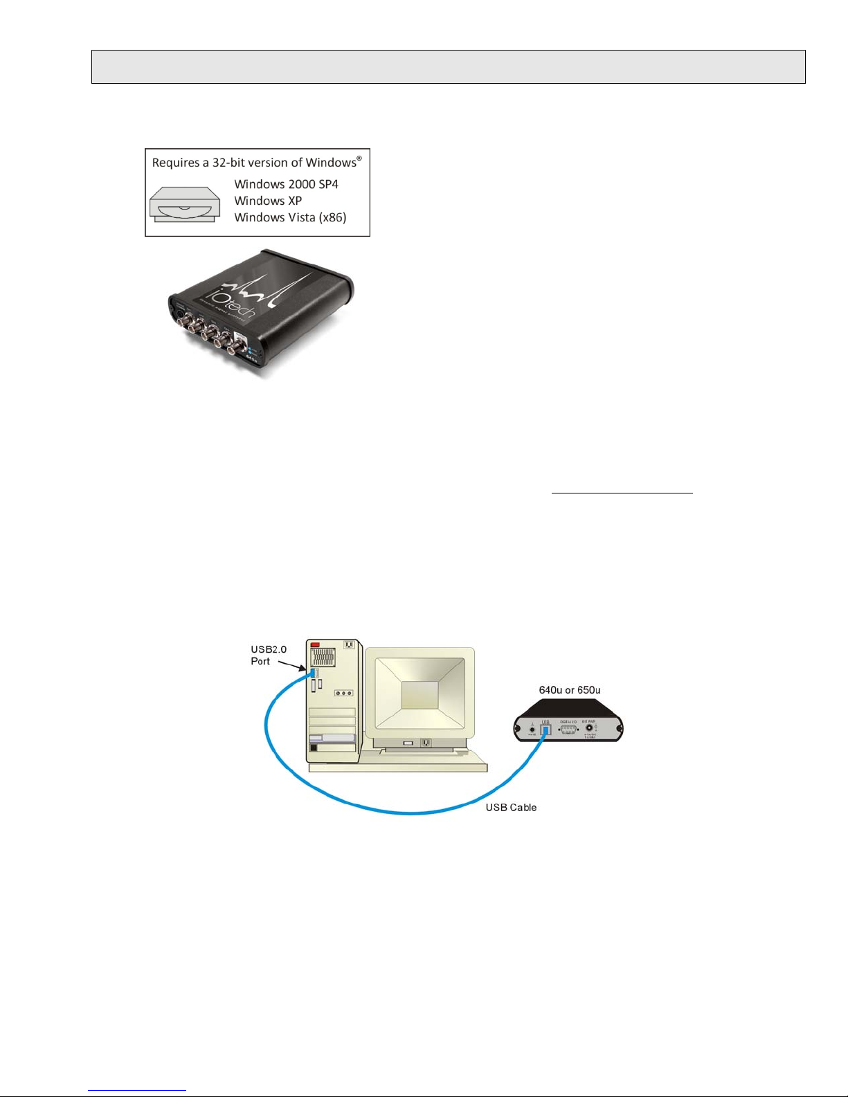
Before you get started verify that you have a 32-bit version
2. Insert the Dynamic Signal Analysis CD into your CD-ROM drive and wait for the CD to auto-run. An Opening
Screen will appear. As an alternative, you can download software from:
of Windows, the following items, and meet or exceed the
minimum requirements listed.
• 640u or 650u
• USB Cable
• USB2.0 port
• Dynamic Signal Analysis CD
• License Keys for purchased software;
e.g., eZ-Analyst, eZ-TOMAS, eZ-Balance, eZ-NDT
Monitor: SVGA, 1024 x 768 screen resolution
•
• Windows 2000 SP4 and Windows XP users:
Intel
1 GB memory; 10 GB disk space
• Windows Vista (x86) users:
PC must be Windows Vista Premium Ready
[on PC]
™
Pentium 4 or equivalent
www.iotech.com/ftp.html
3. Click the <ENTER SETUP> button.
Note: If you are downloading software from our website, follow instructions provided there.
4. From the hardware selection screen [which follows a licensing agreement], select the 640, 650 product-line
from the drop-down list and follow the on-screen instructions.
Step 2 - Connect the 640 u or 650u to the Computer
1. Using a USB cable, connect the 640u [or 650u] to a USB2.0 port on the computer. USB2.0 port is required.
2. Follow the computer screen prompts as directed to allow the computer to detect your new hardware.
Note:
Power LED: The “Power” LED blinks during device detection and initialization; then remains on solid
as long as the module has power. If there is insufficient power the LED will go off.
Active LED: This LED is on whenever active communication is taking place between the 640 [or 650]
and the host PC. Note that the Active LED will be on solid during a data acquisition.
324540C-01

Step 3 - Connect Data Acquisition Signal Lines
Reference Notes:
Prior to making signal connections review the Specifications chapter of your user’s manual to ensure that
the input signals do not exceed the spec ified limits. T he manual is included in PDF format on the CD.
The 640u
4 analog channe l inputs (CH1 thr ough CH4) via fro nt panel BNC co nnectors.
1 analog output via the fifth front panel BNC connector.
8 digital I/O lines via rear panel DB9 connector, as discussed in Chapter 3 of the user’s manual.
The 650u
5 analog channe l inputs (CH1 thr ough CH5) via fro nt panel BNC co nnectors.
8 digital I/O lines via rear panel DB9 connector, as discussed in Chapter 3 of the user ’s manual.
Adobe Acrobat PDF versions of documents pertaining to IOtech 640u and 650u are automatically
installed onto your PC’s hard-drive as a part of product support at the time of software installation.
The default location is the Programs group. It can be accessed via the Windows Desktop Start Menu.
E-mail: productsupport@iotech.com
IOtech
25971 Cannon Road
Cleveland, OH 44146-1833
Phone: (440) 439-4091
Fax: (440) 439-4093
E-mail: sales@iotech.com
Internet: www.iotech.com
*324540C-01*
324540C-01
Printed in Hungary
 Loading...