

Page 1
iOptron® CEM120 Center-Balanced Equatorial Mount
Product #7300, #7301 & #7302
Instruction Manual
1
Page 2

Read the Instruction BEFORE setting up and using the mount! Worm/gear system damage due
to improperly use will not be covered by warranty.
If you have any questions please contact us at support@ioptron.com
NEVER USE A TELESCOPE TO LOOK AT THE SUN WITHOUT A PROPER FILTER!
Looking at or near the Sun will cause instant and irreversible damage to your eye.
Children should always have adult supervision while using a telescope.
WARNING!
2
Page 3

Table of Contents
Table of Contents .................................................................................................................................................... 3
1. CEM120 Introduction ......................................................................................................................................... 6
2. CEM120 Terms ................................................................................................................................................... 7
2.1. Parts List ...................................................................................................................................................... 7
2.2. Identification of Parts ................................................................................................................................... 8
2.3. CEM120 Mount Basic Cable Connection.................................................................................................... 9
2.4. CEM120 Cable Management ....................................................................................................................... 9
2.5. Go2Nova® 8407+ Hand Controller ............................................................................................................ 12
2.5.1. Key Description .................................................................................................................................. 12
2.5.2. The LCD Screen ................................................................................................................................. 13
2.6. Check the Battery ....................................................................................................................................... 14
3. CEM120 Mount Assembly ............................................................................................................................... 15
4. Getting Started .................................................................................................................................................. 22
4.1. Setting the Mount and Performing Polar Alignment ................................................................................. 22
4.2. Manual Operation of the Mount ................................................................................................................ 22
4.3. Push-to Operation of the Mount ................................................................................................................ 22
4.4. The mount can now be used to observe astronomical objects using the HC. Use the arrow keys Initial
Star Alignment .................................................................................................................................................. 22
4.5. GOTO the Moon and Other Objects .......................................................................................................... 23
4.6. Star Identification Function ....................................................................................................................... 23
4.7. Power-Down Memorization....................................................................................................................... 23
4.8. Turning Off the Mount............................................................................................................................... 23
5. Complete Functions of Go2Nova® 8407+ Hand Controller ............................................................................. 24
5.1. Select and Slew .......................................................................................................................................... 24
5.1.1. Solar System ....................................................................................................................................... 24
5.1.2. Deep Sky Objects ................................................................................................................................ 24
5.1.3. Stars..................................................................................................................................................... 24
5.1.4. Comets ................................................................................................................................................ 24
5.1.5. Asteroids ............................................................................................................................................. 24
5.1.6. Constellations ...................................................................................................................................... 24
5.1.7. Custom Objects ................................................................................................................................... 24
5.1.8. Customer R.A. and DEC ..................................................................................................................... 25
5.2. Sync to Target ............................................................................................................................................ 25
5.3. Alignment .................................................................................................................................................. 25
5.3.1. Position of Polaris/SigmaOct .............................................................................................................. 25
5.3.2. One Star Alignment ............................................................................................................................ 25
5.3.3. Two Star Alignment ............................................................................................................................ 25
5.3.4. Three Star Alignment .......................................................................................................................... 26
5.3.5. Solar System Align ............................................................................................................................. 26
5.3.6. Polar Iterate Align ............................................................................................................................... 26
5.3.7. View Model Error ............................................................................................................................... 26
5.3.8. Clear Alignment Data ......................................................................................................................... 26
5.4. Settings ....................................................................................................................................................... 26
5.4.1. Set Time and Site ................................................................................................................................ 26
5.4.2. Beep Settings ...................................................................................................................................... 27
5.4.3. Display Settings .................................................................................................................................. 27
5.4.4. Set Guiding Rate ................................................................................................................................. 27
3
Page 4

5.4.5. Set Tracking Rate ................................................................................................................................ 28
5.4.6. Set Parking Position ............................................................................................................................ 28
5.4.7. Meridian Treatment ............................................................................................................................ 28
5.4.8. Set Altitude Limit ............................................................................................................................... 28
5.4.9. Enable CW Up Position ...................................................................................................................... 28
5.4.10. HC Heating Switch ........................................................................................................................... 29
5.4.11. Set RA Guiding ................................................................................................................................. 29
5.4.12. Network Options ............................................................................................................................... 29
5.4.13. Power LED Switch ........................................................................................................................... 29
5.4.14. Reset All Settings .............................................................................................................................. 29
5.4.15. Language ........................................................................................................................................... 29
5.5. Electric Focuser ......................................................................................................................................... 30
5.6. PEC Option ................................................................................................................................................ 30
5.6.1. PEC Playback...................................................................................................................................... 30
5.6.2. Record PEC ......................................................................................................................................... 30
5.6.3. PEC Data Integrity .............................................................................................................................. 30
5.7. Park Telescope ........................................................................................................................................... 30
5.8. Edit User Objects ....................................................................................................................................... 31
5.8.1. Enter a New Comet ............................................................................................................................. 31
5.8.2. Enter Other Objects or Observation List ............................................................................................ 31
5.9. Firmware Information ................................................................................................................................ 32
5.10. Zero Position ............................................................................................................................................ 32
5.10.1. Goto Zero Position ............................................................................................................................ 32
5.10.2. Set Zero Position ............................................................................................................................... 32
5.10.3. Search Zero Pos. ............................................................................................................................... 32
6. Maintenance and Servicing ............................................................................................................................... 33
6.1. Maintenance ............................................................................................................................................... 33
6.2. iOptron Customer Service .......................................................................................................................... 33
6.3. Product End of Life Disposal Instructions ................................................................................................. 33
6.4. Battery Replacement and Disposal Instructions ........................................................................................ 33
Appendix A. Technical Specifications ................................................................................................................. 34
Appendix B. Go2Nova® 8407+ HC MENU STRUCTURE ................................................................................. 35
Appendix C. Firmware Upgrade ........................................................................................................................... 38
Appendix D. Computer Control a CEM120 Mount.............................................................................................. 39
Appendix E. Go2Nova®Star List .......................................................................................................................... 40
IOPTRON TWO YEAR TELESCOPE, MOUNT, AND CONTROLLER WARRANTY ................................. 46
Ver. 1.0 2018.3
iOptron reserves the rights to revise this instruction without notice. Actual color/contents/design/function may differ from those described in this
instruction manual.
4
Page 5
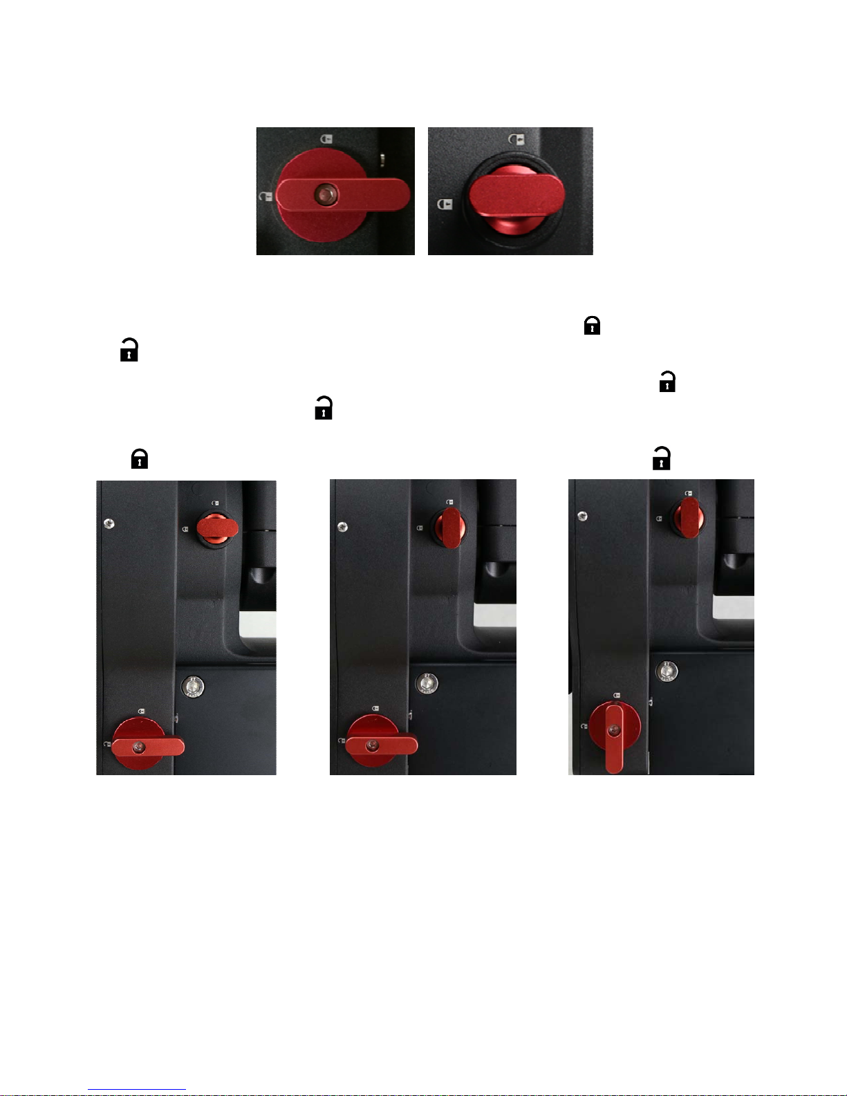
Instruction for CEM120 Gear Switch and Axle Locking Knob
Both RA and DEC have the same Gear Switch and Axle Locking Knob, the operations are the same.
Gear Switch Axle Locking Knob
As an example, here are the positions for the Gear Switch and Axle Locking Knob for RA axis:
A: When transferring or installing the mount, lock the Axle Locking Knob and disengage the Gear
Switch . So the RA won’t swing and there is no force applied onto the worm/ring gear.
B: During mount balancing process, pull and turn the Axle Locking Knob to release it and leave the
Gear Switch at disengaged position . Now the mount will swing freely in RA direction.
C: During normal operation of the mount, i.e., GOTO and tracking, turn the Gear Switch to locking
position to engage the worm/ring gear while leave the Axle Locking Knob released 。
A. During transferring and
installing…
ONLY set the Gear Switch at locking position to engage the worm/ring gear during goto, slew or
tracking.
ALWAYS lock the Axle Locking Knob during transferring and installing.
DO NOT lock both Gear Switch and Axle Locking Knob at the same time.
B. During balancing…
5
C. During operating…
Page 6

1. CEM120 Introduction
Welcome to a new type of equatorial mount – the iOptron® Center-Balanced Equatorial Mount,
or CEM! It offers the benefits of our revolutionary “center balance” design: stability, accuracy, and
smooth mechanical operation, while capable of carrying a payload up to 115 lbs (52 kg). The “center
balance” design’s natural stability is due to its focusing the mount along with payloads weight directly
over the center of the pier or tripod.
The CEM120's performance is demonstrated by its low periodic tracking error: <±3.5 arc
seconds for CEM120 and <0.15 arcsec RMS for CEM120EC/CEM120EC2. Along with the stability
aspect, the CEM120 features an advanced cable management system consisting of more ports in more
locations preventing tangle ups and reducing the chance of fractured cables. It also adds some new
features to the CEM family like Wi-Fi and LAN for remote operation and easy to use, reliable clutches
on both axes.
The CEM120 family has three versions: CEM120 standard version (#7300), CEM120EC
(#7301) with high precision optical encoder on RA axis, and CEM120EC2 (#7302) with high precision
optical encoders on both RA and DEC axes.
The CEM12 mount is equipped with the most advanced GOTONOVA
making it one of the most powerful and accurate GOTO mounts available. TheGo2Nova
controller has a database of over 212,000 objects making it easy to locate even the faintest celestial
objects.
Features:
A new design, center-balanced equatorial mount (CEM) for maximum payload with natural
stability
Observatory astrophotography mount ideal for both visual and Astro-photographers
Payload of 115 lbs (52 kg) with the mount weight of 57 lbs (26 kg)
Easy to use and reliable gear clutches
Precision altitude and azimuth adjustment.
Precision stepper motor with 0.07 arcsec accuracy for precise GOTO and accurate tracking
Polar alignment routine for those who can't see the Pole Star
Go2Nova
heater
High precision tracking with low periodic error: PE<±3.5 arcsec for #7300, or PE <0.15 arcsec
RMS for #7301/#7302
Permanent periodic error correction (PPEC) (#7300) or Real-time periodic error correction
(RPEC) (#7301/#7302)
Push-to operation for CEM120EC and CEM120EC2
Built-in 32-channel Global Positioning System (GPS)
Built-in WiFi and LAN for remote operation
Integrated ST-4 autoguiding port
AutoZero
Power-down memorization of GOTO and tracking position
Advanced cable management system with more choices
Spring loaded, individual adjustable Losmandy saddle
®
8407 V2 controller with Advanced GOTONOVA® GOTO Technology with built in
TM
technology for mount remote operation
®
GOTO technology,
®
8407+ hand
6
Page 7

2. CEM120 Terms
2.1. Parts List1
SHIPPING CONTENTS
Your new CEM120 mount comes in two shipping boxes. One box contains either a CEM120
(#7300), CEM120EC (#7301) or CEM120EC2 (#7302) mount head, hand controller, and accessories.
The other box contains a 22lb (10kg) counterweight and counterweight shaft. The contents are:
1X iOptron
CEM120EC mount (#7301, high precision model with red adjustment knobs), or iOptron
CEM120EC2 mount (#7302,dual high precision model with red adjustment knobs)
1X Go2Nova
1X 22lb (10 kg) counterweight
1X Stainless steel counterweight shaft
1X 12V/5A AC/DC adapter (100V-240V, with 2.5mmX5.5mm plug)
1X Hand Controller Cable (6P6C RJ11 to RJ11, straight wired)
1X Serial cable (RS232 to RJ9)
4X Base mounting screws
1X external GPS antenna
1X Wi-Fi external antenna
®
CEM120 telescope mount (#7300, with silver adjustment knobs), iOptron®
®
8407 V2 Hand Controller
®
OPTIONAL PARTS
Electronic polar scope adapter (#3337-120)
Pier top mounting plate
USB to RS232 Converter with FTDI chipset (#8435)
ONLINE RESOURCES (click on the “Support” menu at www.iOptron.com)
Quick Start Guide
Instructional manual
Tips for set up
Hand controller and mount firmware upgrades (check online for latest version)
iOptron ASCOM driver
Reviews and feedback from other customers
Accessories
1
US market only. Actual contents may vary.
7
Page 8
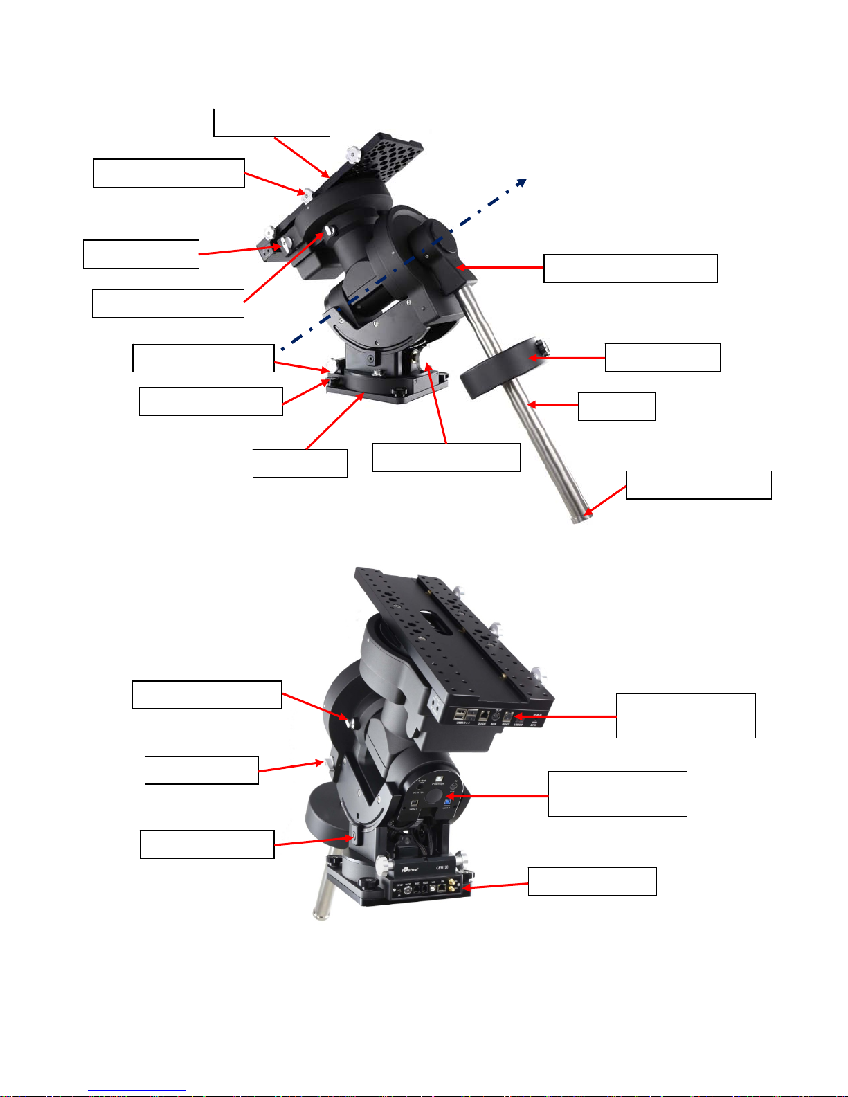
2.2. Identification of Parts
DovetailSaddle
DovetailLockingKnob
DECGearSwitch
DECAxleLockingKnob
AZIAdjustmentKnob
BaseMountingScrew
MountBase
RAAxis
CWShaftMountingHouse
Counterweight
CWShaft
ALTAdjustmentKnob
CWShaftSafetyLock
RAAxleLockingKnob
RAGearSwitch
ALTLockingClamp
Cablemanagement
OutputPanel
Cablemanagement
InputPanel
MountBasicPorts
Figure 1.CEM120 mount assembly
8
Page 9
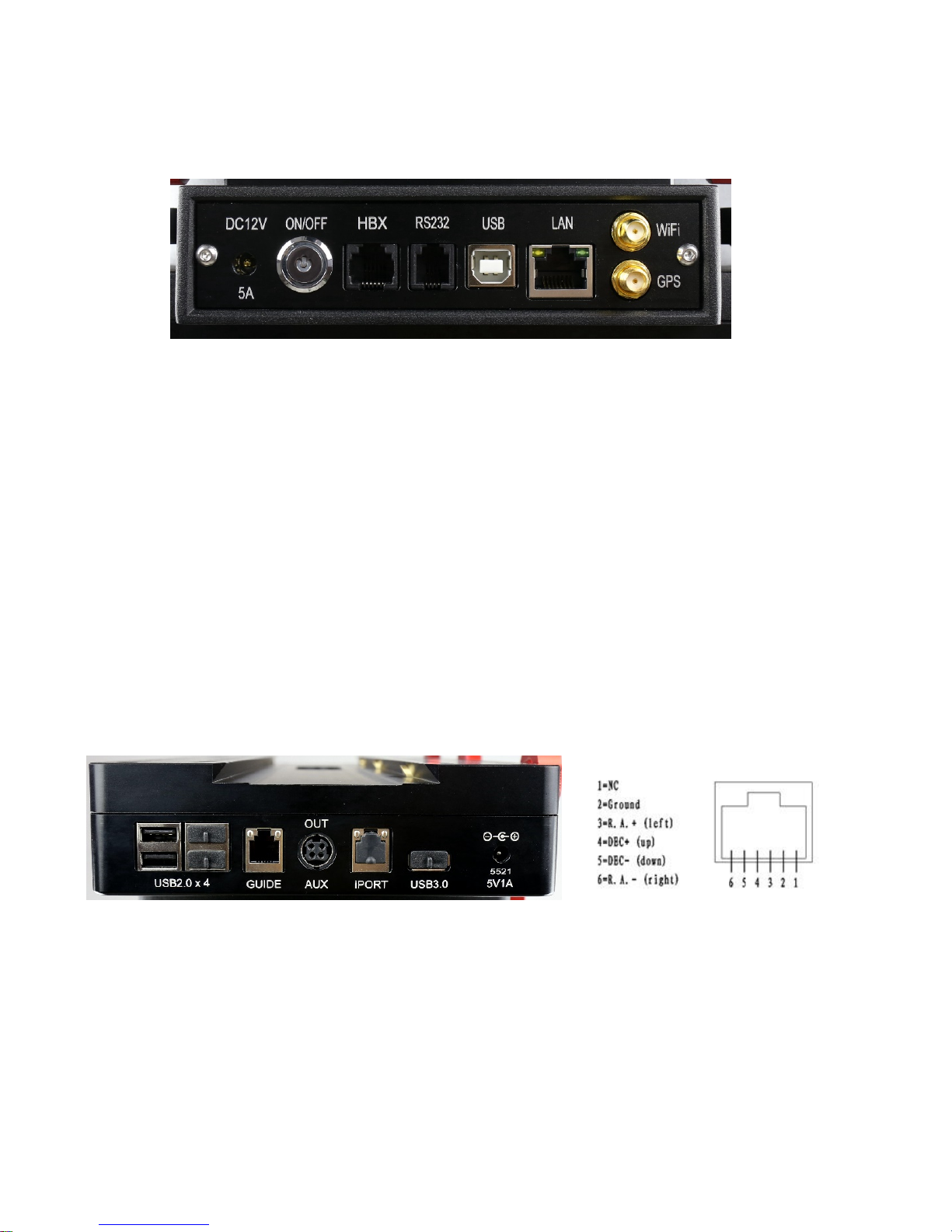
2.3. CEM120 Mount Basic Cable Connection
The basic cable connection ports of a CEM120 mount are all located on the mount base, as
shown in Figure 2.
Figure 2. Ports on a CEM120 mount base
DC 12V 5A: DC power socket to power the mount (2.5mmX5.5mm, 5525)
ON/OFF: Power Switch
HBX (Hand Box): For connecting to an 8407 Hand Controller
RS232: Serial port for mount computer control and firmware upgrade
USB: USB port for mount computer control
LAN: network connection for remote control
WiFi: Mini coaxial cable connector for WiFi antenna
GPS: Mini coaxial cable connector for GPS external antenna
2.4. CEM120 Cable Management
The CEM120 mount has a pre-wired Cable Management System that allows the user to connect
their accessories and imaging equipment without cables tangling or snagging when the mount is
slewing or tracking. The Cable Management Outputs are located at the back of the dovetail saddle, as
shown below.
Figure 3. Connects at the end f the dovetail saddle
At the end of the dovetail saddle, there are
USB 2.0 x 4: 4 USB 2.0 ports with standard type A connectors for connecting accessories
(un powered). They were connected to the USB2.0 input on Input Panel.
GUIDE: port for autoguiding with ST-4 cable. The wiring is shown in Figure 4.
AUX (OUT): A DIN-422 port for high power or other connection purpose. It is connected to
the AUX (IN) port on Input Panel.
Figure 4. GUIDE port wiring
9
Page 10

Figure 5. AUX port DIN-422 socket
iPORT: for iOptron compatible accessories, such as electrical focuser.
USB 3.0: Powered USB 3.0 port. It is connected to the USB3.0 input on the Input Panel.
5521 5V1A socket: a 2.1mmX5.5mm 5V DC power output for accessories. Maximum 1A,
center positive. This is provided by mount DC 12V power.
Figure 6. Power output sockets
On the side of the dovetail saddle, there are 4 power output sockets:
5521 12V1A socket X2: There are two 12V1A DC output sockets on the right end side of the
dovetail saddle, with 2.1mmX5.5mm, center positive sockets. They are provided by mount
DC 12V power.
On the left end side of the dovetail saddle, there are one 5525 (2.5mmx5.5mm) and one
5521 (2.1mmX5.5mm) DC output sockets for your accessories. The maximum specified
current output is 5A. They are connected to the DC IN 10 port on the Input Panel. The
voltage is determined by the input voltage, such as V, 12V or 24V.
Figure 7. Cable Management System Input Panel
10
Page 11

The ports on the Cable Management Panel are connected to the Input Panel located at the end
of the mount RA axis, as shown in Figure 7:
1X DC IN 10A power input (2.5mmX5.5mm, 10A max.)
1X USB 2.0 port with a standard type B connector
1X USB 3.0 port
1X AUX IN port (for data or extra power input)
iPolarScope port for electronic polar scope connection
11
Page 12
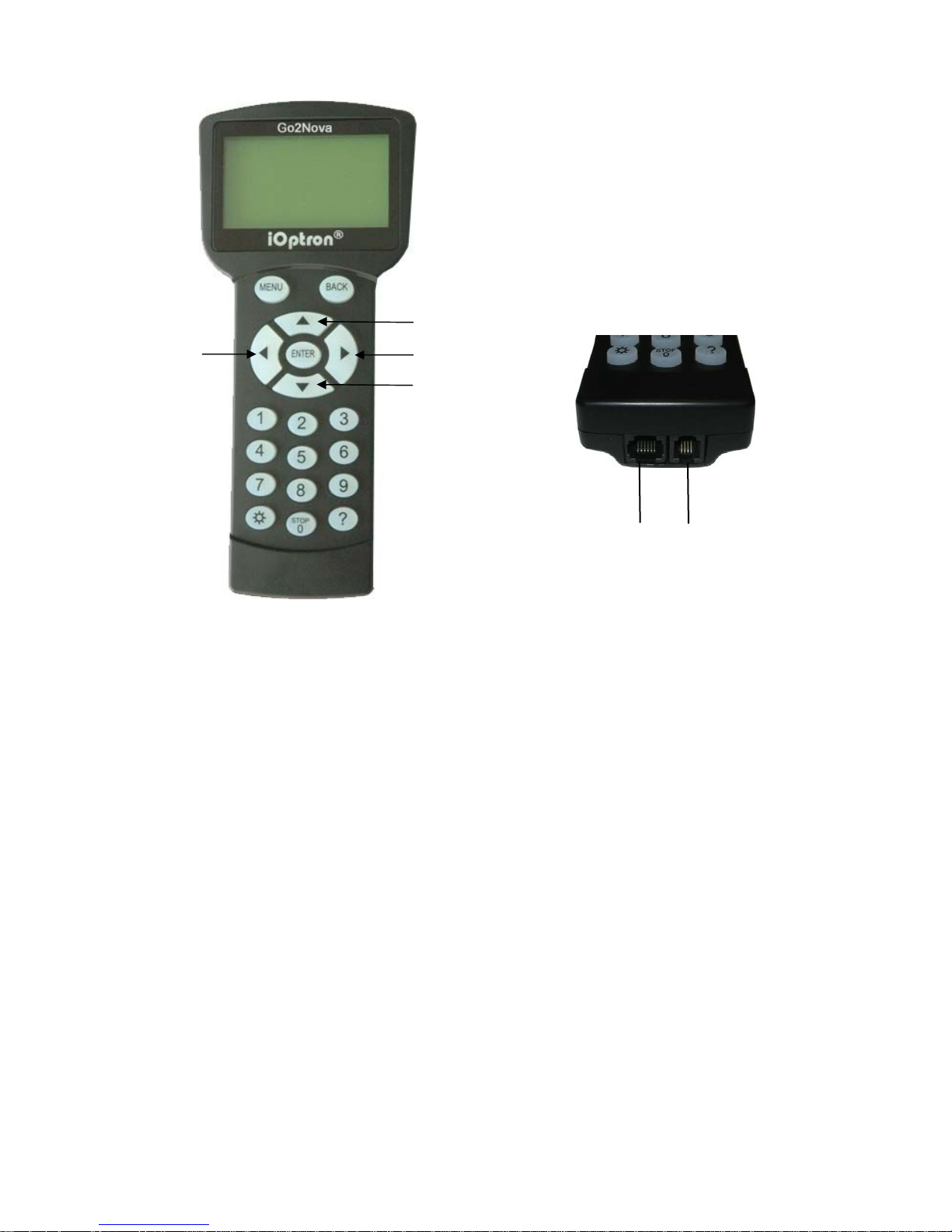
2.5. Go2Nova® 8407+ Hand Controller
DEC+
R.A.+
R.A.-
DEC-
HBX
Port
Serial
Port
Figure 8. Go2Nova® 8407+ hand controller
The Go2Nova® 8407+ hand controller (HC) shown in Figure 8 is the standard controller used on
the CEM120 mount. It has an integrated heater that ensures the LCD display will work at the
temperature as low as -20ºC(-4ºF). It has a large LCD screen, function, direction, and number keys on
the front; a red LED reading light on the back; and a HBX (6-pin) and a serial port (4-pin) at the bottom.
2.5.1. Key Description
MENU Key: Press “MENU” to enter the Main Menu.
BACK Key: Move back to the previous screen, or end/cancel current operation, such as
slewing.
ENTER Key: Confirm an input, go to the next menu, select a choice, or slew the telescope
to a selected object.
Arrow (▲▼◄►) Keys: The arrow keys are used to control the movement of DEC and R.A.
axes. Press and hold ▲(DEC+),▼(DEC-) buttons to move a telescope along the DEC
direction, ◄(R.A.+), ►(R.A.-) to move a telescope along the R.A. direction. They are also
used to browse the menu or move the cursor while in the menu. Press and holding an arrow
key for a fast scrolling.
Number Keys: Input numerical values. Also used to adjust speeds (1: 1X; 2: 2X; 3: 8X; 4:
16X; 5: 64X; 6: 128X; 7: 256X; 8: 512X; 9: MAX)
Light Key(☼): Turns on/off the red LED reading light on the back of the controller.
Help (?) Key: Identify and display bright stars or objects that the telescope is pointing to.
STOP/0 Key: Stop the mount during GOTO. Also toggling between starting and stopping
tracking.
HBX (Handbox) port: connect the HC to a mount using a 6P6C RJ11 cable.
12
Page 13
Serial port: connect the HC to a computer via a RS232 to 4P4C RJ9 cable. The pin-out of
the serial port is shown in Figure 9.
Figure 9. Serial port pin-out on an 8407+ hand controller
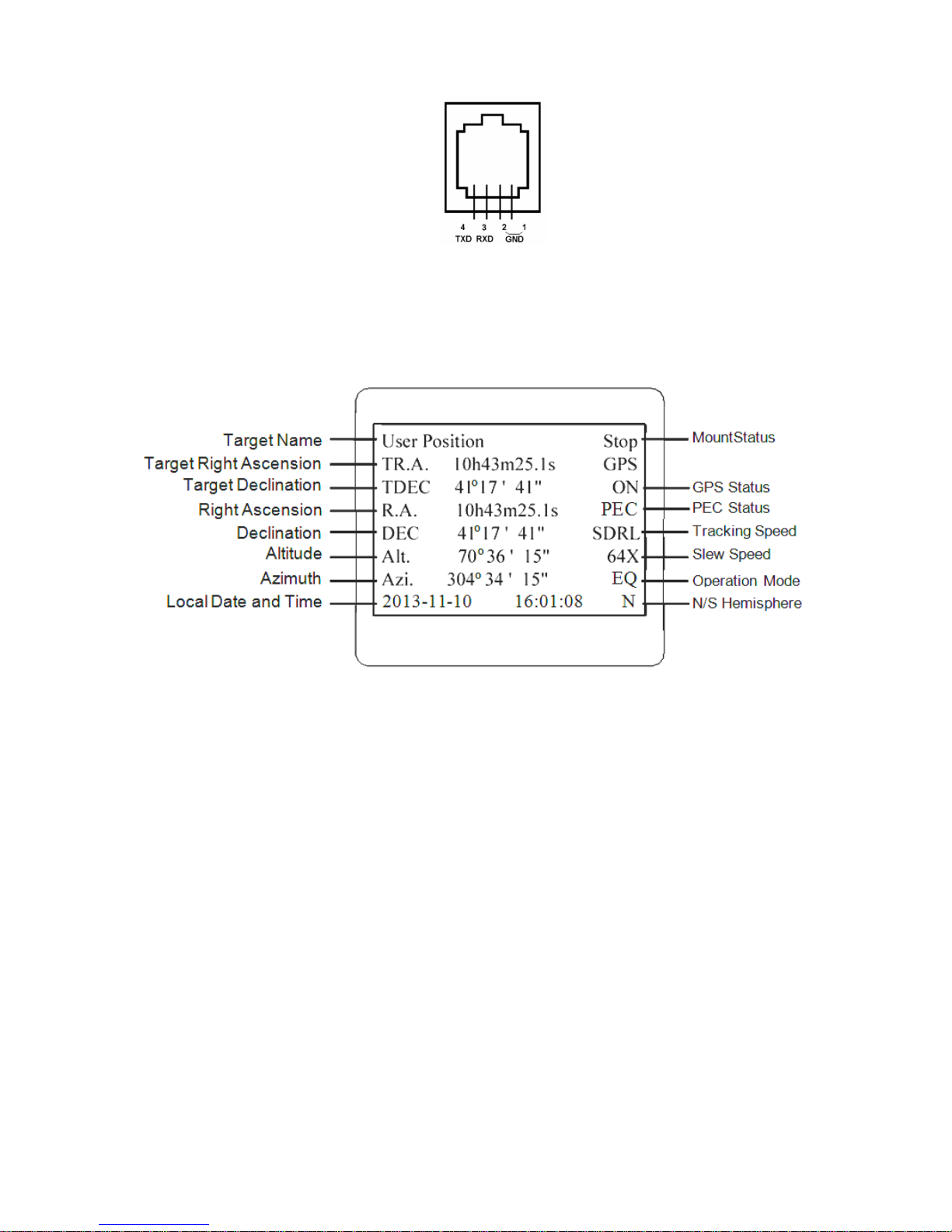
2.5.2. The LCD Screen
The 8407+ HC has a large 8-line, 21-character per line, LCD screen which displays information
on the status of the mount as shown in Figure 10.The user interface is simple and easy to operate.
Figure 10. 8407+ HC LCD Information Screen
1. Target Name/Mount Position: displays the name of the target that telescope is currently pointed to
or the current mount position.
Zero Position: The reference position for GOTO. The mount can move to Zero Position
using “Goto Zero Position” or “Search Zero Position” command;
User Position: The mount is pointed to a user defined position, which could be a particular
celestial object or simply a position determined by pressing an arrow key;
An object name, such as “Mercury” or “Andromeda Galaxy”: Name of the star or celestial
object that the mount is currently slewing to or tracking.
2. Target R.A.: Right Ascension (R.A.) of the target object.
3. Target Declination: Declination (DEC) of the target object.
4. Right Ascension: Current R.A. of the telescope.
5. Declination: Current DEC of the telescope.
6. Altitude: Altitude of the telescope (degrees vertical from the local horizon - zenith is 90º).
7. Azimuth: Azimuth of the telescope (north is 0º, east is 90º, south is 180º, and west is 270º).
8. Local Date and Time: displays the local time in a format of YY-MM-DD HH:MM:SS.
9. Mount Status: Displays the current operational status of the mount.
Stop: mount is not moving;
13
Page 14

Slew: mount is moving with an arrow key is pressed or a GOTO command, such as “Select
and Slew” or “Goto Zero Position”;
Tracking: mount is at a tracking status.
10. GPS status: When the power is turned on, the initial GPS status will be “GPS ON”, which means
that the mount is connected to its GPS receiver and is seeking a satellite signal. When the GPS
receiver finds the satellites and receives the GPS signal the status will change to “GPS OK”.
11. PEC status: Display of “PEC” here Indicates the Periodic Error Correction playback is turned on.
Default is off.
12. Tracking speed: Displays the current tracking rate of the mount.
SDRL: mount is tracking at sidereal speed;
Solar: mount is tracking at solar speed;
Lunar: mount is tracking at lunar speed;
King: mount is tracking at king speed;
CSTM: mount is tracking at a custom, user-defined speed.
13. Slew speed: The mount has 9 slew speeds: 1X, 2X, 8X, 16X, 64X, 128X, 256X, 512X,
MAX(4°/sec).
14. Operation Mode: EQ indicates that the mount is operating in an equatorial mode.
2.6. Check the Battery
The hand controller has a real time clock (RTC) which should display the correct time every time
the mount is turned on. If the time is incorrect, please check the battery inside the hand
controller and replace it if needed. The battery is a 3V, CR1220 button battery.
14
Page 15

3. CEM120 Mount Assembly
STEP 1. Attach the Mount
Make sure that the RA axle is at the locking position (please refer to the charts on page 5).
Remove the mount from the package. Put it onto a pier/tripod top and secure it with four included Base
Mounting Screws.
(a) (b)
Figure 11. (a) Attach the mount, and (b) mount base dimension
Because of the total weight of the mount, counterweight and payload, we recommend use your
own pier for the mount. The base dimension is shown in
STEP 2. Install the Counterweight (CW) Shaft
Hold the mount head with one hand. Pull the RA Axle Locking Knob outward to disengage the
lock. Slowly rotate the mount RA 90 degree to level position. Release the RA Axle Locking Knob to lock
the RA axis again.
Figure 12. Install CW shaft
15
Page 16

Remove the CW shaft from the package and threaded it onto the CW shaft mounting house. DO
NOT release the RA Axle Lock before the CW shaft is fully threaded in. The CW shaft is designed to
balance the mount head weight.
DO NOT rock the counterweight shaft rigorously. It may damage the worm system.
STEP 3. Adjust Altitude
This step requires you to know the latitude of your current location. This can be found from your
8407+ hand controller after the embedded GPS receives the signal from the satellites. It can also be
easily found on the Internet, using a GPS satellite-navigation system, or a GPS capable cell phone.
You will have to change this latitude setting every time you significantly change your night sky viewing
location. Note that this setting directly affects the mount’s GOTO accuracy.
Altitude
Adjustmentknob
Altitudelocking
clamp
Figure 13. Setting the latitude
Slightly loosen the Altitude Locking Clamps about a quarter (1/4) turn with a 5mm Allen wrench,
on both side of the mount. Turn the Altitude Adjustment Knob until the arrow points to your current
latitude on the Latitude Scale, as shown in Figure 13. Tighten the Altitude Locking Clamps when done.
The altitude adjustment employs worm gear system and can be adjusted precisely when turn in
one direction. The fine adjustment is 0.5 arcmin.
The mount latitude adjustment range is from 0° to 68°. For those low latitude places between
0° to 10°, special low latitude CWs (#7326LL) are needed. Please specify when order.
Figure 14. Latitude Adjustment Knob
STEP 4. Install the Counterweight(s) and Telescope
Before installing the Counterweight(s), make sure that mount is at Zero Position, i.e., CW shaft
is pointing to ground. Both R.A. and DEC Axle Locking Knobs are at the locking position (refer to
Illustration A on page 5).
Remove the CW Safety Cap at the end of CW Shaft. Guide the CW over the shaft. Tighten the
CW Locking Screw to hold the CW in place. Place the Safety Cap back onto the shaft.
WARNING: The mount should always be kept in the zero position while it is being loaded
with CWs and payload.
16
Page 17

Figure 15. Loading counterweight
You may need more CWs for heavier payload, or smaller size CW for lighter scope.
The CEM120 has a Losmandy-D dovetail saddle plate, as shown in Figure 16. Release the
dovetal saddle locking knobs and slide the telescope dovatal plate into the saddle. Tighten the saddle
locking knob.
Figure 16. CEM120 dovetail saddle plate
17
Page 18

STEP 5. Balance the Payload
j
After attaching the scope and accessories, the mount head assembly must be balanced in both
R.A. and DEC axes to ensure minimum stresses on the mount driving mechanism.
CAUTION: The telescope may swing freely when the R.A. or DEC during the balancing process.
Always hold on to the mount and/or telescope assembly before releasing the Axle Locking
Knob and/or Gear Switches to prevent it from swinging, which can cause personal injury and/or
equipment damage.
With the corresponding Gear Switch disengaged, balance in DEC axis by moving the scope with
accessories back and forth in the mount saddle. Balance the assembly in R.A. axis by moving CW
along its shaft.
Only balance one axis at a time and start with the DEC axis first. Double check the mount to
make sure both the RA and DEC axes are balanced.
Return the mount to the Zero Position after balancing; i.e., the CW shaft points to ground, and
the telescope tip is at its highest position.
STEP 6. Connect Cables
®
Plug in a 12V DC power supply to the DC12V POWER socket; connect the Go2Nova
8407
Hand Controller to the HBX port on the mount side panel; and install Wi-Fi antenna (right angle one)
and GPS antenna, as shown in .
STEP 7. Setup Hand Controller
The CEM120 mount is equipped with a GPS receiver which will receive the UTC time, longitude
and latitude information for your current location from satellites after a link is established. However,
there are still some parameters which need to be entered to reflect your location, such as time zone
information and whether daylight saving time is currently in effect. This information will be stored in the
mount until they need be updated.
The GPS with an external antenna should make the mount to connect the satellites in a few
minutes. If the GPS module has difficulty receiving the satellite signal, you may manually enter the
information.
To set up the controller, press MENU =>“Settings”:
Select and Slew
Sync. to Target
Alignment
Settings
Electric Focuser
PEC Options
Park Telescope
Edit User Ob
ects
Press ENTER and select “Set Time & Site”
18
Page 19

Set Time and Site
Beep Settings
Display Settings
Set Guiding Rates
Set Tracking Rate
Set Parking Position
Meridian Treatment
Set Altitude Limit
Press ENTER. A time and site information screen will be displayed:
Daylight Saving Time Y
UTC -300 Minute(s)
2014-03-09 10:19:18
Longitude:W071°08’50”
Latitude: N42°30’32”
Northern Hemisphere
Set Local Time
The time will be updated automatically when the GPS receiver has established its link with the
GPS satellites. In the event that the GPS module is unable to establish a link to the satellites, local time
can be entered manually. Use the ◄ or ► key to move the cursor _ and use the number keys to
change the numbers. Use the ▲ or ▼ button to toggle between “Y” and “N” for Daylight Saving Time,
or “+” and “-“ for UTC (Coordinated Universal Time) setting. Hold the arrow key to fast forward or
rewind the cursor.
In order to make the Hand Controller reflect your correct local time, time zone information has
to be entered. Press the ◄ or ► key, move the cursor to the third line “UTC -300 Minute(s)” to set the
time zone information (add or subtract 60 minutes per time zone). For example:
Boston is “UTC -300 minutes”
Los Angeles is “UTC -480 minutes”
Rome is “UTC +60 minutes”
Beijing is “UTC +480 minutes”
Sydney is “UTC +600 minutes”
All the time zones in North America are “UTC –“, as shown in the following table, so ensure the
display shows “UTC -” instead of “UTC +” if in North or South America.
Time Zone Hawaii Alaska Pacific Mountain Central Eastern
Hour behind UT -10 -9 -8 -7 -6 -5
Enter UTC -600 -540 -480 -420 -360 -300
To adjust minutes, move the cursor to each digit and use the number keys to input the number
directly. Use ▲ or ▼ key to toggle between “+” and “-”. When the time one information entered is
correct, press ENTER and go back to the previous screen. Note that fractional time zones can be
entered.
Do not manually add or subtract an hour from displayed time to reflect Daylight Saving Time
(DST). Only select “Y” after DST begins.
For other parts of the world you can find your “time zone” information from internet.
19
Page 20

Set Observation Site Coordinates
The third and fourth lines display the longitude and latitude coordinates respectively. The
longitude and latitude coordinates will be automatically updated when the GPS picks up a satellite
signal. “W/E” means Western/Eastern Hemisphere; “N/S” means Northern/Southern Hemisphere; “d”
means degree; “m” means minute; and “s” means second.
If, for any reason, your GPS does not pick up the satellite signal, you can manually enter your
longitude and latitude coordinates. Press the ◄ or ► key to move the cursor, use the ▲ or ▼ key to
toggle between “W” and “E”, and “N” and “S”, and use the number keys to change the numbers. It is
always a good idea to do your homework and get longitude and latitude coordinates before traveling to
a new observation site.
The site coordinates information can be found from your smart phone, GPS receiver or via the
internet. Site information in decimal format can be converted into d:m:s format by multiplying the
decimal numbers by 60. For example, N47.53 can be changed to N47º31'48”: 47.53º = 47º +0.53º,
0.53º=0.53x60'=31.8', 0.8'=0.8x60"=48". Therefore, 47.53º=47º31'48" or 47d31m48s.
Select N/S Hemisphere
The Northern/Southern Hemisphere will be selected automatically when the latitude is set,
unless the latitude is near the equator. When the latitude is between -10° ~ +10°, set it to Northern
Hemisphere if the polar axis is pointing to North, or Southern Hemisphere if the polar axis is pointing to
South.
STEP 8. Polar Alignment
In order for an equatorial mount to track properly, it has to be accurately polar aligned. A
CEM120 mount does not come with an optical polar scope. There are a few ways to perform the polar
alignment.
Polar Alignment Software
There are quite a few alignment software available or polar alignment, such as TPoint with The
Sky software, PemPro, or Alignmaster
Optional Electronic Polar Scope
A CEM120 has a built-in USB connection (iPolarScope port) for an electronic polar scope. With
a proper adapter, an electronic polar scope, such as PoleMaster can be installed onto the mount and
ready to use.
Figure 17. CEM120 with an installed electronic polar scope
20
Page 21

BrightStar Polar Alignment/Polar Iterate Align
BrightStar Polar Alignment allows you to polar align the mount even if you cannot view the
Celestial Pole.
(1) Level the CEM120 mount and set it at Zero Position. Make sure the telescope is parallel to
the pole axis (R.A. axis) of the mount. If a finder scope is used, adjust it to be parallel to the
telescope optical axis. Turn the mount power on.
(2) Pressing MENU=>“Alignment”=>“Polar Iterate Align”. The HC will display the azimuth and
altitude position of several bright stars near meridian. Select one that is visible with high
altitude as Alignment Star A. Follow the HC instruction to move the Star A to the center of
the eyepiece with the combination of Latitude Adjustment Knob and “◄” or “►” button.
Press ENTER to confirm. Next, select a bright star that is close to the horizon as the
Alignment Star B. Center it using the Azimuth Adjustment Knob and “◄” or “►” button (The
“▲” and “▼” buttons are not used here). Press ENTER to confirm.
(3) The telescope will now slew back to Star A to repeat above steps. The iteration can be
stopped when it is determined that the alignment error is at the minimum. Press BACK
button to exit alignment procedure.
NOTE: The movement of the alignment star in your eyepiece may not be perpendicular but
crossed, depends on its location in the sky.
STEP 9. Return Mount to Zero Position
After polar alignment and balancing OTA, return the mount to the Zero Position. The Zero
Position is achieved when the CW shaft is pointing towards the ground, with the OTA/dovetail at its
highest position, its axis parallel to the polar axis, and the OTA pointing to the Celestial Pole.
Press MENU => “Zero Position” => “Goto Zero Position”. When the mount stopped, loosen
the DEC and R.A. Gear Switches in turn to adjust the mount to the Zero Position. Engage the clutches
after each adjustment. Or press MENU => “Zero Position” => “Search Zero Position” to go to the
Zero Position.
Please set the zero position if it is the first time using the mount, or the firmware just being
updated. You can always check the Zero Position by using MENU=>”Zero Position”=>”Goto Zero
Position” before each session.
Figure 18. Zero Position
21
Page 22

4. Getting Started
In order to experience the full GOTO capability of GOTONOVA® technology it is very important
to set up the mount correctly before observation.
4.1. Setting the Mount and Performing Polar Alignment
Assemble your CEM120 mount according to Section Error! Reference source not found..
Make sure the mount is leveled. Mount an OTA and accessories, and carefully balance the mount on
both R.A. and DEC axes. Turn the mount power switch on. When the GPS receiver is connected to
satellites, the hand controller LCD will display GPS OK and the mount will have the correct time and
site information (this can also be entered manually as previously described). Polar align the mount.
Always check if the mount is at the Zero Position when the mount is powered on, i.e. with the Always check if the mount is at the Zero Position when the mount is powered on, i.e. with the
counterweight shaft pointing to ground, OTA at the highest position with its axis parallel to the polar axis
and the telescope pointing to the Celestial Pole. Press MENU => “Zero Position” => “Goto Zero
Position” to check it. If the mount is not at the Zero Position, press MENU => “Zero Position” => “Set
Zero Position.” Release the Gear Switch to manually return the mount to Zero Position, or use the
hand controller to slew the mount to Zero Position. Press ENTER to confirm the zero position.
4.2. Manual Operation of the Mount
The mount can now be used to observe astronomical objects using the HC. Use the arrow keys
(►, ◄, ▼, and ▲) to point the telescope to the desired part of the sky. Use the number keys to
change the slewing speed. Press the STOP/0 button to start tracking.
4.3. Push-to Operation of the Mount
Both CEM120EC and CEM120EC2 can be operated for push-to on the axis that is equipped
with a high precision encoder. You may push-to the RA axis of a CEM120EC mount, or both RA and
DEC axes of a CEm120EC2 mount.
To operate the push-to function, make sure that the mount is not at the tracking status. If the
mount is tracking, press STOP/0 button to stop tracking. Release the gear switch. Manually push the
mount to a desired position. Lock the gear switch. Press the STOP/0 button to send the mount tracking
again.
4.4. The mount can now be used to observe astronomical objects using the
HC. Use the arrow keys Initial Star Alignment
Perform a simple one star alignment/synchronization after set up the hand controller to correct
any pointing discrepancy of the Zero Position and to improve the GOTO accuracy.
To perform “One Star Align,” press MENU=>“Alignment”=>“One Star Align”=>ENTER. The
screen will display a list of bright objects for you to select from. Select an object using ▲ or ▼ key.
Then press ENTER. After the mount slews to the target, use the arrow keys to center it in your
eyepiece. Then press ENTER. (More align details in 5.4)
An alternate way is to perform “Sync to Target.” Press MENU=>“Selec t and Slew”=>ENTER.
Browse over the catalogs and select an object. Press ENTER. After the mount slews to the star, press
MENU=>“Sync. To Target”, follow the on-screen instruction to center the star and press ENTER. You
may need to use the number keys to change the slewing speed to make the centering procedure
easier.
22
Page 23

4.5. GOTO the Moon and Other Objects
After performing these set-ups the mount is ready to GOTO and track objects. One of the most
common objects is the Moon.
To slew to the Moon press MENU=>“Select and Slew”=>“Solar System”=>Moon=>ENTER.
The telescope will automatically slew to the Moon and lock on it. It will automatically begin to track once
it locks on. If the Moon is not centered in your eyepiece, use the arrow keys to center the Moon. You
may use “Sync to Target” to improve the tracking.
You may also select other bright celestial objects to start with, such as Jupiter or Saturn.
4.6. Star Identification Function
The 8407+ hand controller has a star identification function. After setting the correct local time
and location and completing polar alignment, slew the telescope to a bright star manually or using the
GOTO function. Press the Help(?) key to identify the star that the telescope is pointing to, as well as
nearby bright stars if there is any.
4.7. Power-Down Memorization
The CEM120 mount can memorize its R.A. and DEC positions if the mount loses its power by
accident, even during high speed slewing. After the power is back, just do a Select and Slew to the
same star when the power is lost. The mount will continue to track the star.
4.8. Turning Off the Mount
When you have finished your observation, simply turn the mount power off and disassemble the
mount and tripod.
If the mount is set up on a pier or inside an observatory, it is recommended that you return the
mount to the Zero Position or park the telescope. This will ensure that there is no need for you to
perform the initial setup again.
23
Page 24

5. Complete Functions of Go2Nova® 8407+ Hand Controller
5.1. Select and Slew
Press MENU => “Select and Slew.” Select an object that you would like to observe and press
the ENTER key.
®
The Go2Nova
buttons to move the cursor. Use the number buttons to enter a number, or the ▼ or ▲ buttons to
change a number. Hold a button to fast scroll through the list. The “ ”symbol indicates that the object
is above the horizon, and the “ ” symbol means it is below the horizon. In some catalogs the stars
below the horizon will not be displayed on the hand controller.
5.1.1. Solar System
There are 9 objects in the Solar System catalog.
5.1.2. Deep Sky Objects
This menu includes objects outside our Solar System such as galaxies, star clusters, quasars,
and nebulae.
Named Objects: consists of 92 popular deep sky objects with their common names. A list of
named deep sky objects is included in Appendix E.
Messier Catalog: consists of all 110 Messier objects.
8407+ hand controller has a database of over 212,000 objects. Use the ► or ◄
NGC Catalog: consists of 7,840 objects.
IC Catalog: consists of 5,386 objects.
PGC Catalog: consists of 73,197 objects..
Caldwell Catalog: consists of 109 objects.
Abell Catalog: consists of 4,076 objects.
Herschel Catalog: consists of 400 objects.
5.1.3. Stars
Named Stars: consists of 259 stars with their common names. They are listed alphabetically;
a list is included in Appendix E.
Double/Multi Stars:: consists of 208 double/multi stars; a list is attached in Appendix E.
Hipparcos Catalog: the new HIP catalog consists of 120,404 records (2008).
5.1.4. Comets
This catalog contains 15 comets.
5.1.5. Asteroids
This catalog contains 116 asteroids.
5.1.6. Constellations
This catalog consists of 88 modern constellations. They are listed alphabetically; a list is
attached in Appendix E.
5.1.7. Custom Objects
This allows the storage of up to 73 user-defined comets, and /or up to 64 stars/DSOs.
24
Page 25

5.1.8. Customer R.A. and DEC
Here you can go to a target by entering its R.A. and DEC coordinates.
5.2. Sync to Target
This operation will match the telescope's current coordinates to the Target Right Ascension and
Declination. It can be used to correct GOTO pointing error. After slewing to an object, press MENU then scroll to “Sync to Target” and press ENTER. Follow the screen to perform the sync. Using this
function will re-align the telescope to the selected object. Multiple syncs can be performed if needed.
This operation is useful to find a faint star or nebula near a bright star.
“Sync to Target” will work after “Select and Slew” is performed. You can change the slew rate
to make the centering procedure easier. Simply press a number (1 through 9) key to change the speed.
The default slew rate is 64x.
“Sync to Target” will improve the local GOTO accuracy near by the synced star, which is useful
for finding a faint object nearby.
5.3. Alignment
This function is used for aligning the telescope to the celestial pole and to create a sky model to
calibrate the mount’s GOTONOVA
The hand controller provides a polar alignment via “Polar Iterate Align,” which uses a set of 2
bright. This also provides a viable polar alignment approach for those who can’t see the pole.
The system provides four alignment methods to calibrate the mount’s GOTO function: “Solar
System Align”, “One Star Alignment”, “Two Star Alignment” and “Three Star Alignment”. The “Two
Star Alignment” may be used to refine the polar alignment.
The mount has to be at Zero Position before performing any alignment.
®
functionality.
5.3.1. Position of Polaris/SigmaOct
This function displays the position of the Pole Star. In the Northern Hemisphere the position of
Polaris is displayed, while in the Southern Hemisphere the position of Sigma Octantis is shown.
5.3.2. One Star Alignment
Press MENU => “Alignment” => “One Star Alignment.” A list of alignment stars that are above
the horizon is computed based on your local time and location. With the mount in the Zero Position, use
the▲ and ▼ buttons to select a star and press ENTER. Center the target in your eyepiece using the
arrow keys. Press ENTER when finished. If your mount is set up correctly and polar aligned, one star
alignment should be sufficient for good GoTo accuracy. To increase the pointing accuracy over the sky,
you may choose to do a three star alignment.
5.3.3. Two Star Alignment
Two Star Align can improve the accuracy of the mount’s polar alignment. Press MENU =>
“Alignment” => “Two Star Alignment” A list of alignment stars that are above the horizon is computed
based on your local time and location. With the mount at the Zero Position, use the ▲ and ▼ buttons to
select the first alignment star and press ENTER. Center the target in your eyepiece using the arrow
keys after the mount slews to it. Press ENTER when finished. The hand controller will prompt you to
choose a second star. After centering the second star, the two-star alignment is finished.
After the two-star alignment, the altitude and azimuth errors will be displayed. This number can
be used to fine tune the polar alignment.
25
Page 26

For example, if the screen shows 7.5" low and 4.3" east, it means that THE MOUNT axis is
pointing low and to the east of the Celestial Pole.
5.3.4. Three Star Alignment
The three-star alignment will further determine the cone error between the OTA and mount axis.
The system will use these data to calculate the goto model. If the cone error is big enough, it is
suggested to shim the OTA in DEC to minimize it.
Press MENU => “Alignment” => “Three Star Alignment.” A list of alignment stars that are
above the horizon is computed based on your local time and location. With the mount at the Zero
Position, use the▲ and ▼ buttons to select the first alignment star and press ENTER. Center the target
in your eyepiece using the arrow keys. Press ENTER when finished. The hand controller will prompt
you to choose a second star. Select third star after the mount aligned to the second star.
The system will display the pointing and cone errors after the three star alignment accepted.
The system will update the pointing model accordingly.
5.3.5. Solar System Align
This function uses a planet or the moon as an alignment object. Press MENU => “Alignment”
=> “Solar System Align” for a list of available alignment objects.
5.3.6. Polar Iterate Align
This alignment method allows you to polar align the mount even if you cannot view the Celestial
Pole. Press the MENU button, then select “Alignment” and “Polar Iterate Align”. The HC will display a
list of bright alignment stars near the meridian as Alignment Star A. Follow the HC instructions to move
Alignment Star A to the center of the eyepiece using a combination of the Latitude Adjustment Knob
and the “◄” and “►” buttons. Press ENTER to confirm the settings. Next, select a bright star that is
close to the horizon as Alignment Star B. Center it using the Azimuth Adjustment Knobs and the “◄”
and “►” buttons (the “
▲”
and “
▼”
buttons will not function). Press ENTER to confirm the settings.
The telescope will now slew back to Alignment Star A to repeat the above steps. The iteration
can be stopped when it is determined that the alignment error has been minimized. Press the BACK
button to exit the alignment procedure.
NOTE: It is highly recommended to use an eyepiece with illuminated crosshairs for accurate
centering.
NOTE: The movement of the alignment star in your eyepiece may not be perpendicular
depending on its location in the sky.
5.3.7. View Model Error
This will display linear RA error, linear DEC error, polar misalignment, non-perpendicular
between OTA and DEC, and non-perpendicular between HA and DEC.
5.3.8. Clear Alignment Data
This will clear all alignment data created during one star, two star or three star alignment
process. If you are control the mount using planetarium software via ASCOM, and the software has its
own alignment function, please clear the alignment data.
5.4. Settings
5.4.1. Set Time and Site
Refer to STEP 7 in Section 3.
26
Page 27

5.4.2. Beep Settings
The Hand Controller allows a user to turn off the beep partially, or even go to a silent mode. To
change this setting press “MENU =>Settings =>Beep Settings”,
Set Up Time and Site
Beep Settings
Display Settings
Set Guiding Rates
Set Tracking Rate
Set Parking Position
Meridian Treatment
Set Altitude Limit
Select one of three available modes:
"Always On” – a beep will be heard on each button operation or mount movement;
“On but Keyboard” – a beep will be heard only when the mount is slewing to the object or
there is a warning message;
“Always Off” – all sounds will be turned off, including the SUN warning message.
5.4.3. Display Settings
Press MENU => “Settings” => “Set Display”,
Set Up Time and Site
Beep Settings
Display Settings
Set Guiding Rates
Set Tracking Rate
Set Parking Position
Meridian Treatment
Set Altitude Limit
Use the arrow keys to adjust LCD display contrast, LCD backlight intensity, and keypad’s
backlight intensity.
5.4.4. Set Guiding Rate
Press MENU => “Settings” => “Set Guiding Rates”,
Set Up Time and Site
Beep Settings
Display Settings
Set Guiding Rates
Set Tracking Rate
Set Parking Position
Meridian Treatment
Set Altitude Limit
This is an advanced function for autoguiding when a guiding camera is utilized either via a
Guide Port or using the ASCOM protocol. Before autoguiding, align the polar axis carefully. Select an
appropriate guiding speed. The latest firmware allow you to set the R.A. and DEC guiding speed
differently. The R.A. guiding speed can be set between ±0.01X to ±0.90X sidereal rate. The DEC
guiding speed can be set between ±0.10X to ±0.99X sidereal rate. Follow the instructions of your
autoguiding software for detailed guiding operation.
The guide port wiring is shown in Figure 4, which has the same pin-out as that from a Celestron
/ Starlight Xpress / Orion Mount / Orion Autoguider/ QHY5 autoguider.
27
Page 28

If you have an autoguider which has the same pin-out as the ST-I from SBIG, such as Meade/
Losmandy/ Takahashi/ Vixen, make sure a proper guiding cable is used. Refer to your guiding camera
and guiding software for detailed operation.
WARNING: DO NOT plug your ST-4 guiding camera cable into the iPORT or HBX port. It
may damage the mount or guiding camera electronics.
5.4.5. Set Tracking Rate
You can set up the mount tracking rate by selecting “Set Tracking Rate”.
Set Up Time and Site
Beep Settings
Display Settings
Set Guiding Rates
Set Tracking Rate
Set Parking Position
Meridian Treatment
Set Altitude Limit
Then the user can select “Sidereal Rate”, “Lunar Rate”, “Solar Rate”, “King Rate”, and “User
Defined Speed”. The “User defined speed” can be adjusted from 0.9900X to 1.0100X of sidereal.
The “King Rate”, developed by Edward S. King, corrects the tracking rate of a telescope to
account for atmospheric refraction. This is more useful for unguided tracking.
5.4.6. Set Parking Position
You may park the telescope before powering off the mount. This is very useful if the mount is on
a permanent pier or the mount will not be moved in between observation sessions. The mount will keep
all the alignment info and reference points.
There are six parking positions. Two positions that park the scope horizontally (Horizon
Position). Two positions that park the scope vertically (Zenith Position). “Current Position” will park
the scope at its current position. Alternatively, you can enter any altitude and azimuth combination for
“Custom Parking Pos.”. When the mount is turned on, it will use the last parking position setting as the
default setting.
5.4.7. Meridian Treatment
This function tells the mount what to do when it tracks past the meridian. You can tell the mount if it
needs a meridian flip and when to do it.
“Set Position Limit” will tell the mount when to stop tracking or to do a meridian flip. The limit
can be set at from 0° to 14° (1 hour) pass meridian.
“Set Behavior” will tell the mount if a meridian flip will be performed.
5.4.8. Set Altitude Limit
This function allows the mount to keep tracking an object even if it is below the horizon but can
still be seen, for example from an elevated observation site, such as a hill. The range can be set from -
89° to +89°. The default limit is 00°. Be careful when setting this limit. It may cause mount goto
problems.
5.4.9. Enable CW Up Position
This setting will allow the CW moving to a up position. The upward angle limit is same as the
meridian flipping setting, or 14 degree at maximum. When this set is enabled, the mount will goto pass
the meridian if a object is close to the meridian, within the angle limit. There will be no meridian flip
when pass the meridian.
28
Page 29

5.4.10. HC Heating Switch
Turn on/off the controller LCD back heater. When “Heating ON” is selected, the heater will
automatically be turned on when the ambient temperature reaches 0°C (32°F) and shut off at 10°C.
5.4.11. Set RA Guiding
The function is for CEM120EC only. You can turn off R.A. guiding by selecting “Filter R.A.
Guiding” to allow the high precision encoder to correct the tracking error, or turn the R.A. guiding on by
selecting “Allow RA Guiding” to allow the mount to receive guiding corrections from the guiding
software. The power on default setting is “Allow RA Guiding”.
5.4.12. Network Options
This function will display WI-FI and LAN status.
Wireless Status: displays WI-Fi network parameter after a computer/tablet/SmartPhone
connected to the mount. The CEM120 network SSID is HI-LINK_XXXX, password
12345678. If the status does not display, select and press Manual Refresh to refresh. Here
is a example screen after connection:
Wlan:AP
SSID:HI-LINK_9E49
IP:192.168.16.254
PORT:8080
MAC:08:EA:40:83:9E:48
Press BACK to exit
Wired Status: display LAN parameters after the mount is connected to a network/router. If
the status does not display, select and press Manual Refresh to refresh. Here is a example
screen after connection:
ETH:AP
IP:192.168.0.61
PORT:8080
MAC:08:EA:40:83:9E:49
Press BACK to exit
Manual Refresh: Refresh mount netwark parameter after connection.
Restart: restart the network adapter
Restore to Factory: restore the factory network setting
5.4.13. Power LED Switch
Use this setting to keep the mount power indicator (LED) on during the operation, or turn it off
automatically after 1 minute
5.4.14. Reset All Settings
Reset all the settings to factory default.
5.4.15. Language
Select one of supported menu languages. Currently has English and Chinese.
29
Page 30

5.5. Electric Focuser
This function controls an iOptron electric focuser.
5.6. PEC Option
This function only works for a standard CEM120 mount.
5.6.1. PEC Playback
You can turn “PEC Playback On” to improve tracking accuracy which is especially useful for
long exposure astrophotography. The default status is “PEC Playback Off” when the mount is turned
on.
5.6.2. Record PEC
All equatorial mounts have a small variation in the worm gears which may be corrected by using
Period Error Correction or PEC. PEC is a system which improves the tracking accuracy of the mount by
compensating for variations in the worm gear and is especially useful when doing astrophotography
without autoguiding. Because the variations are regular, it is possible to record the corrections required
to cancel out the worm gear variations and to play them back to correct the periodic error caused by the
variations.
In order to use the PEC function, the Go2Nova
periodic error. The periodic error of the worm gear drive will be used to correct periodic error.
®
hand controller first needs to record the
We recommend using a guiding camera to record the PE with autoguiding. Here’s how to use
the PEC function:
1. Setup the mount with a telescope in autoguiding configuration by connecting a guiding
camera via the mount’s Guide Port or using the ASCOM protocol;
2. Select “MENU=>Settings => Set Guiding Rates”. Set a guiding speed from 0.10X to 0.90X.
The default setting is 0.25X;
3. Then press the BACK button and select “PEC Option” from the menu. Use the ▲ and ▼
scroll buttons to display the “Record PEC” option and press ENTER to start recording the periodic
error.
4. It takes the worm gear 240 seconds to make one complete revolution. After 240 seconds
PEC will automatically stop recording. The PEC value will be permanently stored inside PEC chip on
R.A. motor drive until a new data are recorded.
5. If you want to re-record the periodic error, select “Record PEC” and repeat the recording
processes again. The previously recorded information will be replaced with the current information.
5.6.3. PEC Data Integrity
This function will check the recorded PEC data integrity.
5.7. Park Telescope
This function parks the scope to one of four preset park positions.
30
Page 31

5.8. Edit User Objects
Besides various star lists available in the hand controller, you can add, edit or delete your own
user-defined objects. This is especially useful for newly found comets. You can also add your favorite
observation object into the user object list for easy sky surfing.
5.8.1. Enter a New Comet
Press “MENU =>Edit User Objects” to set user objects.
User Defined Comet
Other Objects
Select “User Defined Comet” to add/browse/delete the user-defined comet list. Find the orbit
parameters of a comet in the SkyMap format. For example, the C/2012 ISON has an orbit parameter:
No. Name Year M Day q e ω Ω I H G
C/2012 S1 ISON 2013 11 28.7960 0.0125050 1.0000030 345.5088 295.7379 61.8570 6.0 4.0
Select “Add a New Comet” to add a new one:
Add a New Comet
Browse Comets
Delete a Comet
Delete All Comets
The hand controller will display the parameter entry screen:
Enter Comet Parameter
Date: 0000-00-00.0000
q: 0.000000
e: 0.000000
ω: 000.0000
Ω: 000.0000
i: 000.0000
Enter the parameters using the arrow buttons and number keys. Press ENTER and a
confirmation screen will be displayed. Press ENTER again to store the object under the assigned user
object number, or press BACK button to cancel.
5.8.2. Enter Other Objects or Observation List
Press “MENU =>Edit User Objects” to set user objects.
User Defined Comet
Other Objects
Select “Other Objects” to enter you own object:
Add a New Object
Browse Objects
Delete One Object
Delete All Objects
31
Page 32

Select “Add a New Object”. A screen will be displayed asking you to Enter R.A. and DEC
coordinates:
Enter R.A. and DEC
R.A.: 00h00m00s
DEC: +00d00m00s
You may enter the R.A. and DEC coordinates of the object you want to store, and press ENTER
to confirm.
A more useful application of this function is to store your favorite viewing objects before heading
to the field. When the “Enter R.A. and DEC” screen appears, press the MENU button. It brings up the
catalogs that you can select the object from. Follow the screen instructions to add your favorite objects.
Press BACK button to go back one level.
Press the BACK button to go back to the object entry submenu. You may review the records or
delete those that are no longer wanted. Press the BACK button to finish the operation. Now you can
slew to your favorite stars from “Custom Objects” catalog using “Select and Slew.”
5.9. Firmware Information
This option will display the mount type, firmware version information for the hand controller
(HC), Main board (Main), R.A. board (RA), DEC board (DEC) and star catalog.
5.10. Zero Position
5.10.1. Goto Zero Position
This moves your telescope to its Zero Position.
5.10.2. Set Zero Position
This set the Zero Position for the firmware.
The Zero Position reference will be an undefined value after firmware upgrade, or it may lost
during power outage or HC battery replacement. You can use this function to set the zero position
reference.
Press the ENTER after moving the mount to Zero Position either manually or with the hand
controller.
5.10.3. Search Zero Pos.
In the event of power failure, the mount will lose all its alignment information. This can be very
troublesome if the mount is being operated from a remote observation site and is controlled via the
internet. To counter this, the CEM120 has been equipped with a function that can find the Zero Position
for an initial mount set up.
Select “Search Zero Pos.” and the mount will start to slew slowly and find the R.A. and DEC
position to set the mount to the Zero Position. When the mount has found the Zero Position, the HC will
ask if you want to calibrate the Zero Position. Press ENTER to confirm. The mount will then provide a
list of bright stars for you to perform alignment. This will correct any discrepancy in the Zero Position.
Alternatively, press BACK to cancel.
32
Page 33

6. Maintenance and Servicing
6.1. Maintenance
The CEM120 mount is designed to be maintenance free. Do not overload the mount. Do not
drop the mount as this will damage the mount and / or permanently degrade GoTo performance and
tracking accuracy. Use a wet cloth to clean the mount and hand controller. Do not use solvent.
If your mount is not to be used for an extended period, dismount the OTAs and counterweight(s).
6.2. iOptron Customer Service
If you have any question concerning your CEM120 mount contact iOptron Customer Service
Department. Customer Service hours are from 9:00 AM to 5:00 PM, Eastern Time, Monday through
Friday. In the event that the CEM120 requires factory servicing or repairing, write or call iOptron
Customer Service Department first to receive an RMA# before returning the mount to the factory.
Please provide details as to the nature of the problem as well as your name, address, e-mail address,
purchase information and daytime telephone number. We have found that most problems can be
resolved by e-mails or telephone calls, so please contact iOptron first to avoid returning the mount for
repair.
It is strongly suggested that to send technical questions to support@ioptron.com
U.S. 1.781.569.0200.
6.3. Product End of Life Disposal Instructions
This electronic product is subject to disposal and recycling regulations that vary by
country and region. It is your responsibility to recycle your electronic equipment per your
local environmental laws and regulations to ensure that it will be recycled in a manner
that protects human health and the environment. To find out where you can drop off your
waste equipment for recycling, please contact your local waste recycle/disposal service
or the product representative.
6.4. Battery Replacement and Disposal Instructions
Battery Disposal: Batteries contain chemicals that, if released, may affect the
environment and human health. Batteries should be collected separately for recycling,
and recycled at a local hazardous material disposal location adhering to your country and
local government regulations. To find out where you can drop off your waste battery for
recycling, please contact your local waste disposal service or the product representative.
. Call in the
33
Page 34

Appendix A. Technical Specifications
Mount Center‐balancedEquatorialMount(CEM)
Payload 52kg(115lbs),excludecounterweight*
Mountweight 26kg(57lbs)
Payload/Mountweightratio 2
Material Allmetal
Latitudeadjustmentrange 0°~68°(0.5arcmindivision)**
Azimuthadjustmentrange ±5°(3arcmindivision)
RightAscensionwormwheel Φ216mm,360teeth,zerobacklash
Declinationwormwheel Φ216mm,360teeth,zerobacklash
Worm Φ26mm
PEC PPEC/RealtimePEC
PE ~±3.5arcsecp‐p(#7300)or<0.15arcsecRMSfor5min(#7301)
Wormperiod 240sec
Counterweightshaft Φ38,540mm(SS,anti‐slip,4.5kg)
Counterweight 10kg(22lbs)
Mountbasesize 210x230mm
Motordrive Steppermotor
Resolution 0.07arcseconds
Slewspeed 1×,2×,8×,16×,64×,128×,256×,512×,MAX(~4°/sec)
Powerconsumption 0.7A(Tracking),1.8A(GOTO)
Powerrequirement 12VDC5A
ACadapter 100V~240V(included)
Polarscope Optionalelectronicpolarscope
HandController Go2Nova®8407+,212,000+objectsdatabase,starrecognition
Meridiantreatment Stop(0‐14°pass),autoflip
Zeroposition Automaticzerosearch
Parkposition Horizontal,vertical,current,alt/aziinput
Levelindicator Yes
Dovetailsaddle LosmandyD,17.2"(437mm)
GPS Yes
Autoguideport ST‐4
Communicationport RS232,USB,LAN,Wi‐Fi
PCcomputercontrol Yes(ASCOM)
Cablemanagement
Operationtemperature ‐10°C~+40°C
Pier/tripod OptionalPier
Warranty Twoyearlimited
*Theseareonlyguidelines.Sometelescopesareverylongorverybigfortheirweightandmayrequirealargermount.
Rememberalsothatimagingrequirementsaremorerigidthanvisualobservation.
**Forlatitudebelow10°,aspecialCWshaftmountinghouseisneeded.
2xDC12V(1A),DC5V(1A),2xDC(5A),ST4,6P6C,4xUSB2.0,
USB3.0(powered),USBforPS,AUX
34
Page 35

Appendix B. Go2Nova® 8407+ HC MENU STRUCTURE
MENU
Select and Slew
Solar System
Mercury
Venus
Mars
Jupiter
Saturn
Uranus
Neptune
Moon
Deep Sky Objects
Named Ob ject
Sun
Stars
Constellations
Comets
Asteroids
Custom Objects
Messier Catalog
NGC
IC
PGC
Caldwell Catalo g
Abell Catalog
Herschel Catalo g
Named Stars
Double/Multi Stars
SAO Catalog
Objects Except Comet
Sync. To Target
User Def ined Comet
Custom R.A. and DEC
35
Page 36

Alignment
Position of Pole Star
One Star Align
Two Star Align
Three Star A lin
Polar Iterate Align
Solar System Align
View Model Error
Clear Alig nment Data
Settings
Set Time & Site
Beep Settings
Display Settings
Electric Fo cuser
PEC Option
Set Guiding Rates
Set Tracking Rate
Set Parking Position
Meridian Treatment
Set Altitude Limit
Enable CW Up Pos.
HC Heating Switch
Network Option
Power LED Switch
Reset All Settingd
Languag e
PEC Playback
Record PE
PEC Data Integrity
Park Telescope
36
Page 37

Edit User Objects
Firmware Information
Zero Position
Custom Comets
Ad d a New Comet
Browse Comets
Delete One Co met
Delete All Comets
Other Objects
Ad d a New Ob ject
Browse Objects
Delete One Object
Delete All Ob jects
Goto Zero Position
Set Zero position
Search Zero position
37
Page 38

Appendix C. Firmware Upgrade
The firmware in the 8407+ Hand Controller and control boards can be upgraded by the
customer. Please check iOptron’s website, www.iOptron.com
select CEM120 for details.
, under Support Directory/CEM Mounts,
38
Page 39

Appendix D. Computer Control a CEM120 Mount
The CEM120 mount can be connected to a computer, a tablet, and/or a SmartPhonebe via serial, USB,
LAN or WI-Fi connection.
Please refer to iOptron website, www.iOptron.com
Telescope ASCOM Driver, for more details.
, under Support Directory/ASCOM Driver, iOptron
39
Page 40

Appendix E. Go2Nova®Star List
Named Deep Sky Object
1 47Tucanae 47 IntegralSignGalaxy
2 AndromedaGalaxy 48 IrisNebula
3 AntennaeGalaxies 49 JellyfishNebula
4 Barnard'sGal ax y 50 JewelBox Cluster
5 Bear‐PawGalaxy 51 LagoonNebula
6 BeehiveCluster 52 LambdaCentauriNebula
7 BlackEyeGalaxy 53 LargeMagellanicCloud
8 BlinkingPlanetary 54 LeoTriplet
9 BlueFlashNebula 55 LittleDumbbellNebula
10 BluePlane tary 56 Littl e GemNe bul a
11 BlueSnowballNebula 57 LittleGhostNebula
12 Bode'sGalaxy 58 MiceGalaxies
13 BoxNebul a 59 Monke yHe adNebula
14 BubbleNebula 60 NorthAmericaNebula
15 BugN e bula 61 NorthernJewelBox
16 ButterflyCluster 62 OmegaNebula
17 ButterflyGalaxies 63 OrionNebula
18 CaliforniaNebula 64 OwlNebul a
19 CarinaNebula 65 PacmanNebula
20 Cat'sEyeNebula 66 PelicanNebula
21 CaveNebula 67 PhantomStreakNebula
22 ChristmasTreeCluster 68 PinwheelGalaxy
23 Ci garGal axy 69 Ple i ade s
24 CocoonNebula 70 RingNebula
25 ComaPinwheel 71 RosetteNebula
26 CopelandSeptet 72 SaturnNebula
27 CrabNebul a 73 Se x tansB
28 CrescentNebula 74 SmallMagellanicCloud
29 DracoDwarfGalaxy 75 SombreroGalaxy
30 DumbbellNebula 76 SoulNebula
31 EagleNebula 77 SouthernPinwheelGalaxy
32 Eight‐BurstNe bula 78 Spindle Galaxy( 3115)
33 ElephantTrunkNebula 79 Spi n dleGalax y(5866)
34 EskimoNebula 80 Stephan'sQuintet
35 EyesGalaxies 81 SunflowerGalaxy
36 FlameNebula 82 TarantulaNebula
37 FlamingStarNebula 83 TheWitchHeadNebula
38 GhostofJupi ter 84 TheWi zardNe bula
39 HeartN e bula 85 Thor'sHe l met
40 HelixNebula 86 TriangulumGalaxy
41 HerculesGlobularCluster 87 TrifidNebula
42 Hind'sVariableNe bula 88 UrsaMinorDwarfGalaxy
43 Hocke yStickGal ax i es 89 Veil Nebula
44 HorseheadNebula 90 WhaleGalaxy
45 Hubble'sVariableNebula 91 WhirlpoolGalaxy
46 HyadesCluster 92 WildDuckCluster
Page 41

Messier Catalog
This table is licensed under the GNU Free Documentation License. It uses material from the Wikipedia
article List of Messier objects
41
Page 42

Named Stars
A
A
1 Acamar 50 Alrescha 99 Deneb el Okab 148 Lalande 21185
2 Achernar 51 Alshain 100 Deneb Kaitos 149 Lesath
3 Achird 52 Altair 101 Denebakrab 150 Mahasim
4 Acrab 53 Altais 102 Denebola 151 Maia
5 Acrux A 54 Alterf 103 Dschubba 152 Marfik
6 Acrux B 55 Aludra 104 Dubhe 153 Marfikent
7 Acubens 56 Alula Australis 105 Edasich 154 Markab
8 Adhafera 57 Alula Borealis 106 El Rehla 155 Markeb
9 Adhara 58 Alya 107 Electra 156 Matar
10 Adid Australis 59 Ancha 108 Elnath 157 Mebsuta
11 Ahadi 60 Ankaa 109 Eltanin 158 Megrez
12 Al Dhanab 61 Antares 110 Enif 159 Meissa
13 Al Dhibain Prior 62 Apollyon 111 Errai 160 Mekbuda
14 Al Kab 63 Arcturus 112 Fomalhaut 161 Menkalinan
15 Al Nair 64 Arkab Prior 113 Furud 162 Menkar
16 Al Nair al Baten 65 Arneb 114 Gacrux 163 Menkent
17 Al Niyat(Sigma) 66 Ascella 115 Gatria 164 Menkib
18 Al Niyat(Tau) 67
19 Albaldah 68
20 Albali 69 Aspidiske 118 Gienah Cygni 167 Mesartim
21 Albireo 70 Atik 119 Girtab 168 Miaplacidus
22 Alchiba 71 Atlas 120 Gliese 1 169 Mimosa
23 Alcor 72 Atria 121 Gomeisa 170 Mintaka
24 Alcyone 73 Avior 122 Graffias(Zeta) 171 Mira
25 Aldebaran 74 Azha 123 Groombridge 1830 172 Mirach
26 Alderamin 75 Barnard's Star 124 Gruid 173 Mirfak
27 Alfirk 76 Baten Kaitos 125 Grumium 174 Mirzam
28 Algenib 77 Beid 126 Hadar 175 Mizar
29 Algenubi 78 Bellatrix 127 Hamal 176 Mu Velorum
30 Algieba 79 Beta Hydri 128 Han 177 Muhlifain
31 Algiedi Secunda 80 Betelgeuse 129 Hatsya 178 Muphrid
32 Algol 81 Betria 130 Head of Hydrus 179 Muscida
33 Algorab 82 Biham 131 Homam 180 Naos
34 Alhakim 83 Birdun 132 Iritjinga(Cen) 181 Nashira
35 Alhena 84 Canopus 133 Izar 182 Navi
36 Alioth 85 Capella 134 Kakkab Su-gub Gud-Elim 183 Nekkar
37 Alkaid 86 Caph 135 Kapteyn's Star 184 Nihal
38 Alkalurops 87 Castor A 136 Kaus Australis 185 Nunki
39 Alkes 88 Castor B 137 Kaus Borealis 186 Nusakan
40 Almaaz 89 Cebalrai 138 Kaus Media 187 Palida
41 Almach 90 Chara 139 Keid 188 Peacock
42 Alnasl 91 Chertan 140 Kekouan 189 Phact
43 Alnilam 92 Choo 141 Kitalpha 190 Phecda
44 Alnitak 93 Cor Caroli 142 Kochab 191 Pherkad
45 Alpha Muscae 94 Cursa 143 Koo She 192 Polaris
46 Alpha Tucanae 95 Dabih 144 Kornephoros 193 Pollux
47 Alphard 96 Deltotum 145 Kraz 194 Porrima
48 Alphecca 97 Deneb 146 Kurhah 195 Procyon
49 Alpheratz 98 Deneb Algedi 147 Lacaille 9352 196 Propus
sellus Austral 116 Giausar 165 Merak
sellus Boreali 117 Gienah Corvi 166 Merope
42
Page 43

197 Proxima Centauri 213 Sadalbari 229 Sulafat 245 Vindemiatrix
198 Rasalas 214 Sadalmelik 230 Syrma 246 Vrischika
199 Rasalgethi 215 Sadalsuud 231 Talitha 247 Wasat
200 Rasalhague 216 Sadr 232 Tania Australis 248 Wazn
201 Rastaban 217 Saiph 233 Tania Borealis 249 Wei
202 Regor 218 Sargas 234 Tarazed 250 W ezen
203 Regulus 219 Scheat 235 Taygeta 251 Yed Posterior
204 Rigel 220 Schedar 236 Tejat Posterior 252 Yed Prior
205 Rigel Kentaurus A 221 Seginus 237 Thuban 253 Zaniah
206 Rigel Kentaurus B 222 Shaula 238 Thusia 254 Zaurak
207 Ruchbah 223 Sheliak 239 Tien Kwan 255 Zavijava
208 Rukbat 224 Sheratan 240 Turais 256 Zeta Persei
209 Rukh 225 Sirius 241 Unukalhai 257 Zosma
210 Rutilicus 226 Skat 242 Vasat-ul-cemre 258 Zubenelgenubi
211 Sabik 227 Spica 243 Vathorz Posterior 259 Zubeneschamali
212 Sadachbia 228 Suhail 244 Vega
43
Page 44

A
A
A
A
A
A
A
A
A
A
AraA
A
A
A
A
A
A
A
Modern Constellations
No.
1
2
3
4
5
6
7
8
9
10
11
12
13
14
15
16
17
18
19
20
21
22
23
24
25
26
27
28
29
30
31
32
33
34
35
36
37
38
39
40
41
42
43
44
Constellation Abbreviation
ndromeda
ntlia
pus
quarius
quila
ries
uriga
Boötes Boo
Caelum Cae
Camelopardalis Cam
Cancer Cnc
Canes Venatici CVn
Canis Major CMa
Canis Minor CMi
Capricornus Cap
Carina Car
Cassiopeia Cas
Centaurus Cen
Cepheus Cep
Cetus Cet
Chamaeleon Cha
Circinus Cir
Columba Col
Coma Berenices Com
Corona Australis Cr
Corona Borealis CrB
Corvus Crv
Crater Crt
Crux Cru
Cygnus Cyg
Delphinus Del
Dorado Dor
Draco Dra
Equuleus Equ
Eridanus Eri
Fornax For
Gemini Gem
Grus Gru
Hercules Her
Horologium Hor
Hydra Hya
Hydrus Hyi
Indus Ind
nd
nt
ps
qr
ql
ra
ri
ur
No.
45
46
47
48
49
50
51
52
53
54
55
56
57
58
59
60
61
62
63
64
65
66
67
68
69
70
71
72
73
74
75
76
77
78
79
80
81
82
83
84
85
86
87
88
Constellation Abbreviation
Lacerta Lac
Leo Leo
Leo Minor LMi
Lepus Lep
Libra Lib
Lupus Lup
Lynx Lyn
Lyra Lyr
Mensa Men
Microscopium Mic
Monoceros Mon
Musca Mus
Norma Nor
Octans Oct
Ophiuchus Oph
Orion Ori
Pavo Pav
Pegasus Peg
Perseus Per
Phoenix Phe
Pictor Pic
Pisces Psc
Piscis Austrinus Ps
Puppis Pup
Pyxis Pyx
Reticulum Ret
Sagitta Sge
Sagittarius Sgr
Scorpius Sco
Sculptor Scl
Scutum Sct
Serpens Ser
Sextans Sex
Taurus Tau
Telescopium Tel
Triangulum Tri
Triangulum Australe Tr
Tucana Tuc
Ursa Major UMa
Ursa Minor UMi
Vela Vel
Virgo Vir
Volans Vol
Vulpecula Vul
Page 45

Double/Multi Stars
1 RigelKentaurus A 53 HIP 95771 105 HIP 40167 157 HIP 28790
2 Rigel 54 HIP 30867 106 HIP 40817 158 HIP 4675
3 Gacrux 55 HIP 35363 107 HIP 81292 159 HIP 31676
4 Sargas 56 HIP 94761 108 HIP 80197 160 HIP 10176
5 Castor A 57 HIP 21683 109 HIP 88060 161 HIP 25950
6 Mizar 58 HIP 8497 110 HIP 42637 162 HIP 117931
7 Almach 59 HIP 26199 111 HIP 21039 163 HIP 81914
8 Algieba 60 HIP 104521 112 HIP 100965 164 HIP 21242
9 Aludra 61 HIP 116389 113 HIP 25768 165 HIP 86831
10 Iritjinga(Cen) 62 HIP 17797 114 HIP 93717 166 HIP 115272
11 Zubenelgenubi 63 HIP 21036 115 HIP 79980 167 HIP 46657
12 Alcyone 64 HIP 107310 116 HIP 12086 168 HIP 41404
13 Cor Caroli 65 HIP 72659 117 HIP 90968 169 HIP 29388
14 Acamar 66 HIP 21029 118 HIP 22531 170 HIP 49321
15 Adhafera 67 HIP 42726 119 HIP 34065 171 HIP 84054
16 Rasalgethi 68 HIP 18255 120 HIP 79607 172 HIP 39035
17 Meiss a 69 HIP 9153 121 HIP 109786 173 HIP 25303
18 Graffias(Zeta) 70 HIP 88267 122 HIP 56280 174 HIP 52520
19 Alya 71 HIP 85829 123 HIP 51561 175 HIP 95398
20 HIP 48002 72 HIP 43937 124 HIP 107930 176 UCAC4 277-135548
21 HIP 95947 73 HIP 71762 125 HIP 97966 177 HIP 32609
22 HIP 20894 74 HIP 80047 126 HIP 117218 178 HIP 101765
23 HIP 74395 75 HIP 58484 127 HIP 82676 179 HIP 24825
24 HIP 27072 76 HIP 25142 128 HIP 111546 180 HIP 31158
25 HIP 26549 77 HIP 54204 129 HIP 29151 181 HIP 3885
26 HIP 85667 78 HIP 76669 130 HIP 107253 182 HIP 93371
27 HIP 74376 79 HIP 99770 131 HIP 88136 183 HIP 36345
28 HIP 34481 80 HIP 101027 132 HIP 81702 184 HIP 108364
29 HIP 53253 81 HIP 74911 133 HIP 97423 185 HIP 50939
30 HIP 99675 82 HIP 35210 134 HIP 30444 186 HIP 76603
31 HIP 63003 83 HIP 26235 135 HIP 66400 187 HIP 32269
32 HIP 43103 84 HIP 40321 136 HIP 17579 188 HIP 42516
33 HIP 110991 85 HIP 70327 137 HIP 35785 189 HIP 62807
34 HIP 20635 86 HIP 26221 138 HIP 81641 190 UCAC4 226-128246
35 HIP 88601 87 HIP 80473 139 HIP 7751 191 HIP 94913
36 HIP 2484 88 HIP 78105 140 HIP 21148 192 HIP 94336
37 HIP 91971 89 HIP 79043 141 HIP 9021 193 HIP 107299
38 HIP 79374 90 HIP 61418 142 HIP 97816 194 HIP 59984
39 HIP 102532 91 HIP 91919 143 HIP 88818 195 HIP 16411
40 HIP 52154 92 HIP 41639 144 HIP 36817 196 HIP 23287
41 HIP 37229 93 HIP 104214 145 HIP 25695 197 HIP 105637
42 HIP 30419 94 HIP 23734 146 HIP 98819 198 HIP 108925
43 HIP 108917 95 HIP 60189 147 HIP 61910 199 HIP 103814
44 HIP 53417 96 HIP 66821 148 HIP 111643 200 HIP 58112
45 HIP 65271 97 HIP 14043 149 HIP 80399 201 HIP 109354
46 HIP 67669 98 HIP 5737 150 HIP 83478 202 HIP 43822
47 HIP 105319 99 HIP 84626 151 HIP 101123 203 HIP 21986
48 HIP 80582 100 HIP 60904 152 HIP 28271 204 HIP 17470
49 HIP 8832 101 HIP 58684 153 HIP 64246 205 HIP 35960
50 HIP 69483 102 HIP 5131 154 HIP 96895 206 HIP 42936
51 HIP 92946 103 HIP 115126 155 HIP 35564 207 HIP 19272
52 HIP 86614 104 HIP 62572 156 HIP 37843 208 HIP 76143
45
Page 46

IOPTRON TWO YEAR TELESCOPE, MOUNT, AND CONTROLLER WARRANTY
A. iOptron warrants your telescope, mount, or controller to be free from defects in materials and workmanship for two years. iOptron
will repair or replace such product or part which, upon inspection by iOptron, is found to be defective in materials or workmanship.
As a condition to the obligation of iOptron to repair or replace such product, the product must be returned to iOptron together with
proof-of-purchase satisfactory to iOptron.
B. The Proper Return Merchant Authorization Number must be obtained from iOptron in advance of return. Call iOptron at
1.781.569.0200 to receive the RMA number to be displayed on the outside of your shipping container.
All returns must be accompanied by a written statement stating the name, address, and daytime telephone number of the owner,
together with a brief description of any claimed defects. Parts or product for which replacement is made shall become the property
of iOptron.
The customer shall be responsible for all costs of transportation and insurance, both to and from the factory of iOptron, and shall be
required to pre-pay such costs.
iOptron shall use reasonable efforts to repair or replace any telescope, mount, or controller covered by this warranty within thirty
days of receipt. In the event repair or replacement shall require more than thirty days, iOptron shall notify the customer accordingly.
iOptron reserves the right to replace any product which has been discontinued from its product line with a new product of
comparable value and function.
This warranty shall be void and of no force of effect in the event a covered product has been modified in design or function, or
subjected to abuse, misuse, mishandling or unauthorized repair. Further, product malfunction or deterioration due to normal wear is
not covered by this warranty.
IOPTRON DISCLAIMS ANY WARRANTIES, EXPRESS OR IMPLIED, WHETHER OF MERCHANTABILITY OF FITNESS FOR A
PARTICULAR USE, EXCEPT AS EXPRESSLY SET FORTH HERE. THE SOLE OBLIGATION OF IOPTRON UNDER THIS
LIMITED WARRANTY SHALL BE TO REPAIR OR REPLACE THE COVERED PRODUCT, IN ACCORDANCE WITH THE TERMS
SET FORTH HERE. IOPTRON EXPRESSLY DISCLAIMS ANY LOST PROFITS, GENERAL, SPECIAL, INDIRECT OR
CONSEQUENTIAL DAMAGES WHICH MAY RESULT FROM BREACH OF ANY WARRANTY, OR ARISING OUT OF THE USE
OR INABILITY TO USE ANY IOPTRON PRODUCT. ANY WARRANTIES WHICH ARE IMPLIED AND WHICH CANNOT BE
DISCLAIMED SHALL BE LIMITED IN DURATION TO A TERM OF TWO YEARS FROM THE DATE OF ORIGINAL RETAIL
PURCHASE.
Some states do not allow the exclusion or limitation of incidental or consequential damages or limitation on how long an implied
warranty lasts, so the above limitations and exclusions may not apply to you.
This warranty gives you specific legal rights, and you may also have other rights which vary from state to state.
iOptron reserves the right to modify or discontinue, without prior notice to you, any model or style telescope.
If warranty problems arise, or if you need assistance in using your telescope, mount, or controller contact:
iOptron Corporation
Customer Service Department
6E Gill Street
Woburn, MA01801
www.ioptron.com
support@ioptron.com
Tel. (781)569-0200
Fax. (781)935-2860
Monday-Friday 9AM-5PM EST
NOTE: This warranty is valid to U.S.A. and Canadian customers who have purchased this product from an authorized iOptron
dealer in the U.S.A. or Canada or directly from iOptron. Warranty outside the U.S.A. and Canada is valid only to customers who
purchased from an iOptron Distributor or Authorized iOptron Dealer in the specific country. Please contact them for any warranty.
 Loading...