

Page 1
SmartStar® N114 Telescope
Instruction Manual
1
Page 2

Table of Content
Table of Content ............................................................................................................................. 2
1. SmarStar
1.1. SmartStar® N114 Features................................................................................................... 4
1.2. SmartStar® N114 Assembly Terms ..................................................................................... 5
2. Telescope Assembly ...................................................................................................................6
3. GOTONOVATM 8405 Hand Controller......................................................................................8
3.1. Key Description...................................................................................................................8
3.2. The LCD Screen .................................................................................................................. 8
4. Getting Started.......................................................................................................................... 10
4.1. Level and Align the Mount................................................................................................ 10
4.1.1. Level the Mount..........................................................................................................10
4.1.2. Initial Positions ...........................................................................................................10
4.2. Setting Up the Mount......................................................................................................... 10
4.2.1. Time and Site Set Up.................................................................................................. 10
4.2.2. Using your telescope...................................................................................................12
4.2.3. Go to the Moon........................................................................................................... 12
4.2.4. Initial Star Alignment ................................................................................................. 12
4.3. Turn Off the Mount............................................................................................................ 13
5. Use SmartStar® N114 ............................................................................................................... 14
5.1. Manual Operation of the Telescope...................................................................................14
5.2. Slew to an Object............................................................................................................... 14
5.2.1. Planets, Sun, Moon..................................................................................................... 14
5.2.2. Deep Sky Objects........................................................................................................ 14
5.2.3. Comets ........................................................................................................................14
5.2.4. Asteroids.....................................................................................................................14
5.2.5. Stars............................................................................................................................. 14
5.2.6. User RA&DEC JD2000 Objects................................................................................. 14
5.2.7. Enter Position.............................................................................................................. 14
5.2.8. Watch List...................................................................................................................14
5.2.9. Watch List Auto..........................................................................................................15
5.3. Land Objects...................................................................................................................... 15
5.4. Sync to Target.................................................................................................................... 15
5.5. Set Up Controller............................................................................................................... 15
5.5.1. Set Display Info .......................................................................................................... 15
5.5.2. Set Key Beep............................................................................................................... 16
5.5.3. Set Azi Work Mode.................................................................................................... 16
5.5.4. Reset All...................................................................................................................... 16
5.6. Align .................................................................................................................................. 16
5.6.1. Solarsys Align.............................................................................................................16
5.6.2. One Star Align ............................................................................................................ 16
5.6.3. Two Star Alignment.................................................................................................... 16
5.7. Modify Star Catalog........................................................................................................... 17
5.7.1. User RA&DEC JD2000.............................................................................................. 17
5.7.2. Comets ........................................................................................................................18
5.7.3. Asteroids.....................................................................................................................19
®
N114 Overview......................................................................................................... 4
2
Page 3

5.8. Watch List..........................................................................................................................19
5.9. Set Telescope Coord..........................................................................................................19
5.10. Park Scope ....................................................................................................................... 19
6. Maintenance and Servicing.......................................................................................................20
6.1. Maintenance....................................................................................................................... 20
6.2. Storage and Transport........................................................................................................ 20
6.3. Troubleshooting................................................................................................................. 20
6.4. iOptron Customer Service.................................................................................................. 21
Appendix A. Technical Specifications ......................................................................................... 22
Appendix B. GOTONOVATM 8405 HC MENU STRUCTURE..................................................23
Appendix C. GOTONOVATM Star List........................................................................................25
IOPTRON ONE YEAR LIMITED WARRANTY....................................................................... 38
WARNING!
NEVER USE A TELESCOPE TO LOOK AT THE SUN!
Looking at or near the Sun will cause instant and irreversible damage to your eye.
Children should always have adult supervision while observing.
3
Page 4

1. SmarStar® N114 Overview
1.1. SmartStar® N114 Features
GOTONOVATM Computerized Control
System
Introducing our SmartStar® N114
computerized GOTO telescope system.
Designed with the latest technology the 114
mm mirror is crafted with aluminum coated
mirrors and exacting alignment.
Alt-Azimuth Mount– The Cube™
The SmartStar® N114 reflector
telescope comes with our patented Alt-
Azimuth Mount, a.k.a. The Cube™. This
compact mount design is one of the most
functional and flexible units on the market.
Sky & Telescope magazine named it “Hot
Product 2008”. Both axis motors are built
into a small single unit with optical encoders
that provide accurate GOTO and tracking.
The mount is universally compatible with all
telescopes using a dove-tail connector plate.
With an optional DC adaptor you can plug
your telescope mount into your car if you’re
camping or at any other remote location.
Easy to understand controller
The GOTONOVATM hand controller
is much easier to use than other similar
products. The hand controller is more
intuitive with menu categories better
organized. It also has a larger LCD screen
with more lines of content compared with
the competition. Using the hand controller
and its large LCD screen you can quickly
set up your telescope and select where you
want to go.
The revolutionary GOTONOVATM
computerized control system is by far the
most technologically advanced automated
tracking system available on the market
today. With a database of 10,000+ celestial
objects including all of the more famous
galaxies, nebulae, star clusters— not to
mention the planets—you’ll be able to enjoy
star gazing with the simple push of a button.
Package Contents1
(1) SmartStar® mount with built-in
GPS receiver (Model #9803 only)
or
(1) SmartStar
®
mount (Model #9503)
(1) Newtonian reflector telescope
(114mm)
(1) GOTONOVATM Hand
Controller (Part # 8405)
(1) Controller cable
(1) Red dot finder scope
(2) Eyepieces (K9mm & K25mm)
(1) Tripod
More precise speed control for
viewing objects
The control system also allows you
to slew the telescope at 5 different drive
speeds, keeping the object within the
telescope’s viewfinder for as long as you
wish.
1
Package contents may vary slightly
4
Page 5
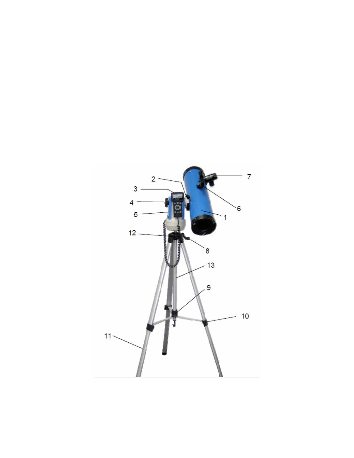
1.2. SmartStar® N114 Assembly Terms
1. Telescope tube
2. Dovetail Lock
3. Hand Controller
4. Altitude Lock
5. Mount
6. Red dot finder scope
7. Eyepiece
8. Height Adjustment Handle
9. Center Tripod Lock Knob
10. Tripod Leg Locks (3)
11. Tripod
12. Tripod Height Lock Knob
13. Height Extender
5
Page 6
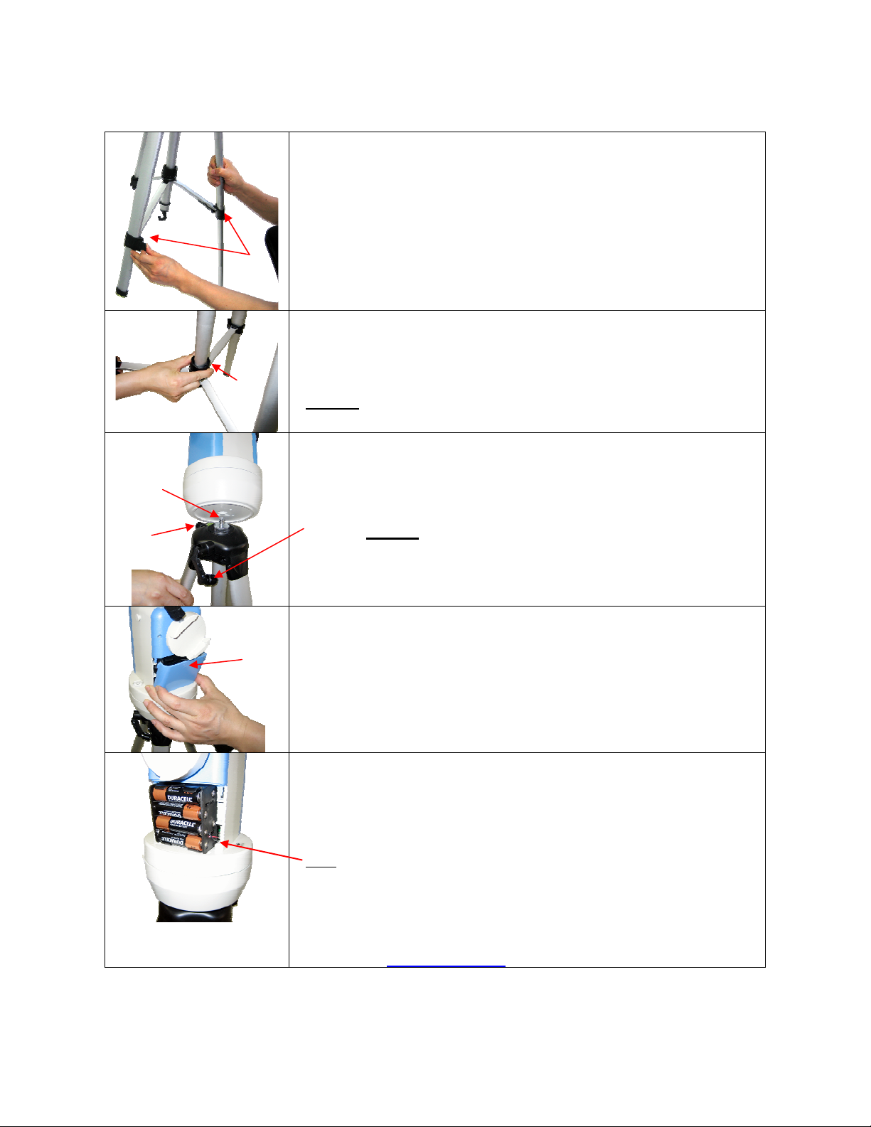
2. Telescope Assembly
Step 1. Preparing the Tripod
Unlock the tripod leg locks (#10).
Extend tripod legs.
Lock the leg locks afterwards.
#10
Step 2.
Pull tripod legs apart to a fully opened position.
Turn the center tripod lock knob (#9) to secure the tripod. Tighten to a
#9
Threaded
bolt
Height lock
(#12)
firm feel.
Caution
the tripod to store away.
Step 3. Attaching the Mount
Attach mount to tripod by placing the mount onto the threaded on
tripod. Then turn the mount until it is securely fastened to the tripod.
Use height adjustment handle (#8) to adjust the height of the mount if
needed. (Caution
Make sure to tighten the tripod height extender lock (#12).
: Make sure you loosen this lock knob before collapsing
: Do not extend beyond 6 inches.)
Step 4. Installing Batteries (not included)
Pull the batteries compartment cover (shown) open.
Gently pull the batteries holder (shown next) out of the compartment to
avoid breaking the attached wires.
Step 4a.
Insert 8 AA batteries (not included) according to the diagrams on the
holder.**
Replace the holder back into the batteries compartment and replace the
cover.
Note
: fit the batteries holder back into the compartment with the
attached wires at the bottom right corner (see arrow in the photo).
** Use only fresh batteries; do not mix fresh and old
batteries;insufficient battery power may cause error
messages;optional AC Adapter and Car Charger accessories are
available at www.ioptron.com
6
Page 7
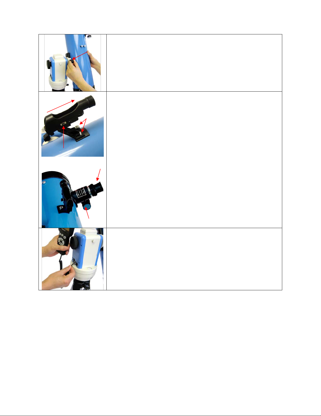
Point toward open end
of telescope
Switch
Dovetail
lock (#2)
Bolts
Eyepiece (#7)
Step 5. Attaching Telescope
Attach telescope to mount using the dovetail lock knob (#2).
Step 6. Attaching Optics
Attaching the red dot finder scope (#6) to the telescope tube (#1):
First remove the two washers on the tube. Then place the finder scope
onto the two bolts and re-attach the washers securely. The finder scope
should face towards the open end of the tube (see arrow in diagram).
Turn on the beam using the switch on the side. (note: you may need to
remove the plastic insulation placed next to the battery underneath)
Insert the eyepiece: Remove the supplied K 25mm eyepiece (#7) from
its container and slide it into the open end of eyepiece holder. Tighten
the thumbscrews to a firm feel only.
Remove the round dust cover lid from the end of telescope.
Use the focus knob to bring objects into focus. You may need to turn
the focus knob quite a few turns to focus your telescope for the first
time. Always start observing using a lower power eyepiece (such as the
K25mm eyepiece) to get a wider field of view. Later on you can change
to higher powers. (Eyepieces of higher powers have narrower field of
views; it’s more difficult to locate objects using high-power eyepieces.)
Focus knob
Step 7. Connecting Hand Controller
Plug hand controller into any one of the HBX (handbox) ports on the
mount.
Turn on power. Now you are ready to observe. Use the 4 Arrow keys
(▲▼◄►) to rotate the scope Up, Down, Left, and Right. Use the
SPEED key to change the slew speed from the slowest (2X) to the
fastest (MAX).
7
Page 8

3. GOTONOVATM 8405 Hand Controller
Figure 1. GOTONOVA 8405 Hand Controller
GOTONOVATM 8405 hand controller (HC) is
the standard controller for a SmartStar
N114 telescope, as shown in Figure 1.
3.1. Key Description
• MENU: Press “MENU” to enter the Main
Menu.
• BACK: Move back to the previous screen,
or end/cancel current operation, such as
slewing.
• ENTER: Confirm an input, go to the next
menu, select a choice, slew the telescope to
a selected object, or stop/start tracking.
• Arrow (▲▼►◄): Press ▲▼ buttons to
move a telescope along the altitude
direction, ►◄ to move a telescope along
the azimuth direction. Brows the menu or
move the cursor in operating menu.
• SPEED Key: To select slew speed (2X,
8X, 64X, 256X, and MAX)
• Light Key (☼): Turns on/off the red LED
reading light on the back of the controller.
• HELP Key: For help and display more
information on an object.
• HBX (handbox) port: connect the HC to
SmartStar mount using a 6-wire RJ11 cable.
3.2. The LCD Screen
The 8405 HC consists of a large 4-line LCD
screen, which displays all the information as
shown in Figure 2. The user interface is
simple and easy to learn.
8
Page 9
Target Name
Mount/GPS Status
Right Ascension
Altitude
Local Date and Time
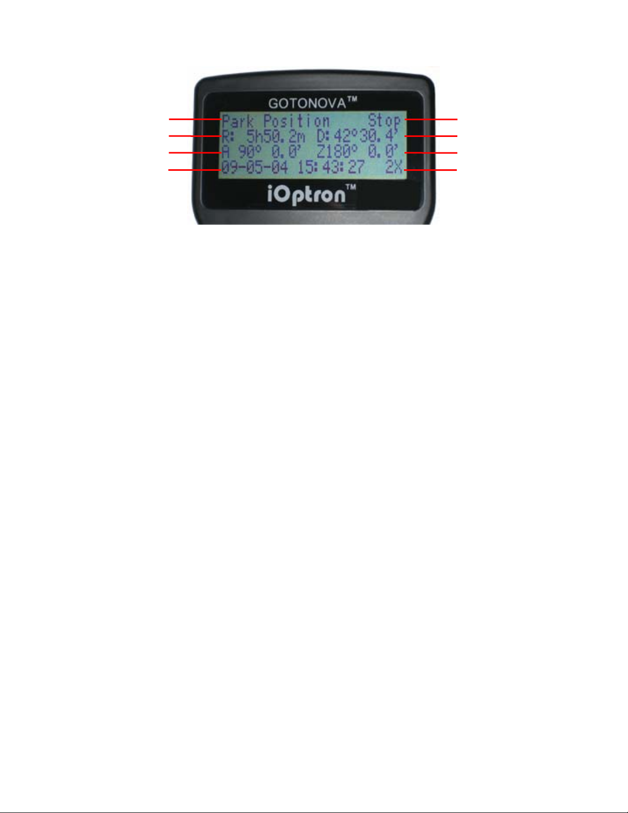
Figure 2. #8405 Hand Controller LCD Information Screen
1. Target Name: displays the name of the
target that telescope is currently pointed to.
• Park Position: A default position
when the mount is turned on, i.e., the
telescope is pointed to zenith (altitude is
90º) and the mount is facing south
(azimuth is 180º);
• An object name, such as “Mercury”
or “Andromeda Galaxy”: Name of the Star
or celestial object currently that is
currently slewing, gotoing or tracking;
• LandMark #: The telescope is
working in Land mode and is pointing to a
land mark # (note: telescope does not
track in land mode)
• User Position: The mount has been
manually slewed to an object; or an R.A
and DEC value of an object was manually
entered; or a goto or tracking process has
been interrupted.
2. Mount/GPS Status: display current
status of the mount. If the mount equipped
with a GPS (integrated GPS receiver or
external GPS module), it also indicates GPS
status, when the mount is turned on.
Stop (Mount Status): the telescope is in a
standby position;
• Slew (Mount Status): the telescope
is manually slewing to the target;
• Goto (Mount Status): the telescope
is going to the target;
• Track (Mount Status): the telescope
is tracking a target;
• Align (Mount Status): the telescope
is in align mode;
Declination
Azimuth
Slew Speed
• G-ON (GPS Status): GPS is on and
trying to lock on to a satellite;
• G-OK (GPS Status): The connection
between GPS receiver and satellites has
been established (This status will be
replaced by Mount Status after a few
minutes).
3. R: Right Ascension of the telescope, or
R.A.
4. D: Declination of the telescope, or DEC.
5. A: Altitude of the telescope (zenith is
90º).
6. Z: Azimuth of the telescope (north is 0º,
east 90º, south 180º, and west 270º).
7. Local Date and Time: display local time
in a format of YY-MM-DD HH:MM:SS.
8. Slew speed: There are 5 speeds: 2X,
8X, 64X, 256X (1º/sec), MAX(4º/sec). Press
the SPEED key to change the speed while
slewing.
9
Page 10
4. Getting Started
In order to experience the full GOTO
capability of GOTONOVA technology it is
important to set up the mount correctly
before observation.
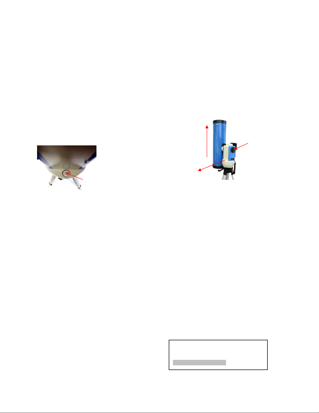
4.1. Level and Align the Mount
4.1.1. Level the Mount.
Leveling is critical for good GOTO and
tracking accuracy.
Level the mount by
observing the
bubble (shown) on
the base of the
mount by adjusting
the tripod legs.
The bubble should
be in the center of
the circle. It is also recommended to use
additional levelers (such as a torpedo
leveler) to assure precise leveling. Turn the
mount around by pressing ► or ◄ button to
make sure it is always leveled during
movement.
4.1.2. Initial Positions
Each time the mount is turned on the default
position is Park Position, (i.e.,its altitude is
90º0.0’ and azimuth is 180º0.0’) which
means the “SOUTH” mark is pointing to
south and the telescope is pointing straight
up at the zenith. To set the Park Position
you can:
1. Align the mount to south by moving the
mount so that the South mark faces south.
An additional compass is needed. Unlock
the altitude lock (#4) and rotate the
telescope to point straight up at the Zenith.
A torpedo level may help. Make sure the
mount is leveled. Then turn the mount
power on.
or
2. Turn the mount power on. Press the
SPEED button to select a slew speed (MAX
for fast slew and 2X for fine tuning). Turn
the SOUTH mark pointing to south using ►
or ◄ button. An additional compass is
needed. Rotate the telescope to point to
zenith using the ▲ or ▼ buttons. A torpedo
level may help. Then turn the mount power
off and turn it on. Or you can press MENU.
Scroll down to “Set Telescope Coord.”
Press ENTER. The default number is “Alt:
90º00.0’ and Azi: 180º00.0’”. Press ENTER
to complete the initialization.
Up
South
Alt. Lock
(#4)
4.2. Setting Up the Mount
For a SmartStar® telescope equipped with a
GPS receiver, the local time, longitude and
latitude information will be received from
satellites after a link is established. For units
without a GPS receiver this information can
be entered manually. Regardless, manual
input is still needed for the time zone and
Daylight Time Saving settings for all
models.
A clear sky outside is needed for GPS to
communicate well with the satellites.
4.2.1. Time and Site Set Up
This is critical to ensure the telescope will
point to the right direction.
Press MENU button. From the main menu
scroll down and select “Set Up Controller”
Select and slew
Land Objects
Sync. to Target
Set Up Controller
10
Page 11
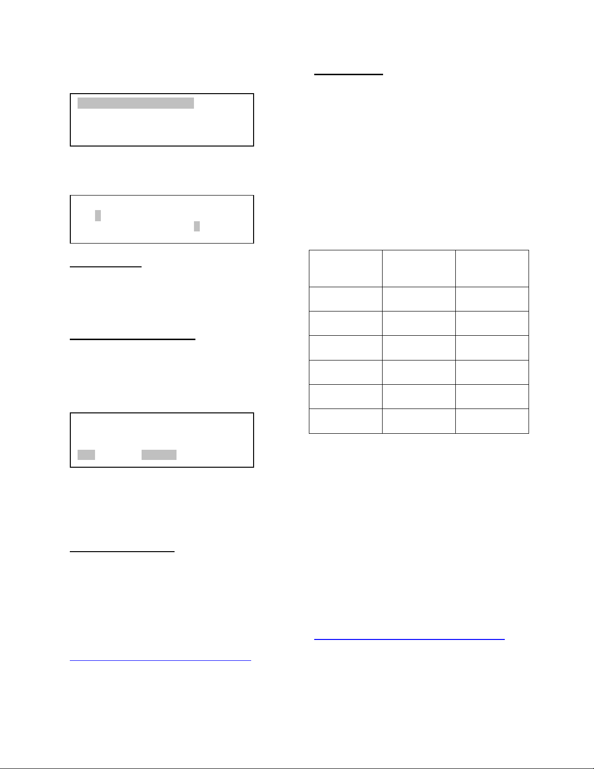
Press ENTER. Select “Set Up Time and
Site”
Set Up Time and Site
Set Display Info
Set Key Beep
Set Azi Work Mode
Press ENTER. The Set Local Time screen
will show:
Set Local Time:
2009-06-01 11:55:09
DaylightTime Saving Y
Set time zone
Press ◄ or ► key. Move the cursor to the
bottom of the screen to set the time zone
information (add or subtract 60 minutes per
time zone). Enter minutes “ahead” or
“behind” of UT (universal time). The
minimum time difference is 15 minutes.
• New York City is 300 minutes “behind”
UT
• Los Angeles is 480 minutes “behind” UT
• Rome is 60 minutes “ahead” of UT
• Beijing is 480 minutes “ahead” of UT
• Sydney is 600 minutes “ahead” of UT
Set local time:
Use the ◄ or ► key to move the cursor,
and the ▲ or ▼ button to change the
numbers.
Set daylight saving time:
Use ▲ or ▼ button to toggle the
DaylightTime Saving between Y and N.
Press ENTER to go to Setup Site Info
screen:
Setup Site Info:
Longi: W071d27m47s
Lati : N42d15m40s
300 Min. behind UT
“W/E” means west/east hemisphere; “N/S”
means north/south hemisphere; “d” means
degree; “m” means minute; and “s” means
second.
Set site coordinates:
Use the ◄ or ► key to move the cursor,
and the ▲ or ▼ button to change the
numbers or toggle between “W” and “E”, “N”
and “S”.
The site coordinates information can be
found online at sites such as GPSVisualizer
http://www.gpsvisualizer.com/geocode
).
Simply enter a city name or address.
Time Zone Hours
behind UT
Enter
Minutes
Hawaii -10 600
Alaska -9 540
Pacific -8 480
Mountain -7 420
Central -6 360
Eastern -5 300
All time zones in North America are behind
UT as shown in the following table (Be sure
it shows “behind” instead of “ahead of” UT).
To adjust minutes, use the ◄ or ► keys to
move the cursor and the ▲ or ▼ keys to
change the numbers. To change the
“behind” or “ahead of” UT, move the cursor
to “ahead of” and using ▲ or ▼ keys to
toggle between “behind” and “ahead of”.
When the number is correct press ENTER
and go back to the previous screen.
For other parts of the world, time zone
information can be found online such as
http://www.timeanddate.com/worldclock/
.
DO NOT COUNT DAYLIGHT SAVING
TIME.
If your mount is equipped with a GPS
receiver only Daylight Time Saving and
11
Page 12

Time Zone settings are needed. However,
the local time and site info can still be
manually entered (in case the GPS signal is
too weak from clouds or buildings). It is
always recommended to get the GPS
coordinates before traveling to a new
observation site.
4.2.2. Using your telescope
3. Now, objects located with the finder
scope first will be centered in field of view of
the main telescope.
4.2.3. Go to the Moon
After performing these setups, the mount is
ready to GOTO and track objects. The most
common object will be Moon.
Selecting an Eyepiece:
1. Always begin viewing with the lowest
power eyepiece. (Note: a 25 mm focal
length eyepiece has a lower power than a 9
mm one.) A formula can be used to
determine the power of each eyepiece:
Telescope focal length divided by eyepiece
focal length equals magnification. Ex.
1000mm ÷ 25mm = 40X (magnification)
2. Astronomical telescopes are designed in
such a way that the image you see may be
UPSIDE DOWN and REVERSED.
Focusing Telescope:
1. After selecting the desired eyepiece aim
the telescope tube at a land-based target at
least 200 yards away (e.g. A telephone pole
or building). Fully extend focusing tube by
turning the focus knob.
2. While looking through selected eyepiece,
slowly retract focusing tube by turning
focusing knob until object comes into focus.
Aligning Finderscope:
Press MENU button, select “Select and
Slew” by press ENTER button. Select
“Planets, Sun, Moon”, and using ▲ or ▼
button to select Moon. Press ENTER. The
telescope will automatically slew to the
Moon and lock on. Press BACK key to stop
GOTO. It will automatically begin to track
once it locks on to it. Use the arrow keys to
center the Moon in your eyepiece, if it is not
centered. Press ENTER key to stop the
tracking.
4.2.4. Initial Star Alignment
A simple alignment/synchronization can be
performed to improve the GOTO and
tracking accuracy. To do so, press MENU
button, scroll down to “Align”, select
“Solarsys Align” and press ENTER. The
screen will list Moon, Sun and other planets
for you to select from. Select an object
using ▲ or ▼ key. Then press ENTER. The
mount will slew to the object. Use ◄ ► ▲
or ▼ key to center the object in your
eyepiece. Press SPEED button to change
the slew speed if needed. Then press
ENTER to complete the alignment. Or press
the BACK key to cancel the process.
1. Look through Main Telescope Tube and
establish a well-defined target (see focusing
telescope section). Tighten all lock knobs
(Declination, Latitude, Right Ascension,
Horizontal Axis) so that telescope’s aim is
not disturbed.
2. Turn on the red dot finder scope and look
through the finder window. Adjust the red
dot alignment screws to center the red dot
on the object.
An alternate way is performing “Sync to
Target”. To do so, press MENU button,
select “Select and Slew” and press ENTER.
Then select a known sky object, such as
Moon from “Planets, Sun, Moon” menu and
press ENTER. The mount will slew to the
Moon. When the mount stopped slewing,
the Moon could be just inside your eyepiece
or way off. Press MENU button and scroll
down the menu to “Sync to Target” and
press ENTER. Follow the instruction, use ◄
► ▲ and ▼ keys to move the Moon in the
center of your eyepiece and press ENTER.
12
Page 13

4.3. Turn Off the Mount
When finishing observing, always move the
mount to Park Position. If the mount is not
moved, no initial set up is needed when
powered on the next time. To do so, press
the MENU button, scroll down to “Park
Telescope” and press ENTER. Turn the
power off.
13
Page 14

5. Use SmartStar® N114
5.1. Manual Operation of the
Telescope
You may observe land and astronomical
objects using GOTONOVA’s arrow keys.
After the telescope was assembled
(referring to Section 2. Telescope
Assembly), flip the ON/OFF switch on the
telescope mount to the ON position. Use
►,◄,▼ or ▲ buttons to point the telescope
to desired object. You may need using
SPEED key to change the slewing speed.
• NGC Catalog: It consists of 7840
objects in NGC catalog. Use ► or ◄
button to move the cursor and ▼ or ▲
button to change the number.
5.2.3. Comets
It contains up to 64 comets. This database
is customer upgradeable.
5.2.4. Asteroids
It contains up to 64 asteroids. This database
is customer upgradeable.
5.2.5. Stars
5.2. Slew to an Object
Press MENU button, from the main menu,
select “Select and Slew.” Select an object
you would like to observe and press ENTER
key.
The GOTONOVA
has a database consists of over 10,000
objects. Use ► or ◄ button to move the
cursor and ▼ or ▲ button to change the
number. “
the horizon, and “
horizon. Only those objects above the
horizon can be observed. In some catalogs,
those stars below the horizon may not
display.
5.2.1. Planets, Sun, Moon
There are 9 objects in Solar system.
5.2.2. Deep Sky Objects
TM
8405 hand controller
”indicates the object is above
” means it is below the
• Named Stars: It consists of 191 stars
with their common names. They are
listed alphabetically. A list is attached in
Appendix C.
• Constellations: It consists of 88 modern
constellations with their names. They
are listed alphabetically. A list is
attached in Appendix C.
• Double Stars: It consists of 211 double
stars. A list is attached in Appendix C.
• SAO Bright Stars: It consists of 5000+
bright SAO catalog objects. They are
listed numerically.
5.2.6. User RA&DEC JD2000 Objects
It can consist up to 256 user predefined
objects. These objects need to be entered
before they can be selected for slewing
(Refer to 5.7.1 User RA&DEC JD2000).
5.2.7. Enter Position
• Named Deepsky Objects: It consists of
137 deep sky objects with their common
names. More information will be
available by pressing HELP key. A list of
named deep sky objects is also
attached in Appendix C.
• Messier Catalog: It consists of all 110
objects in Messier catalog. More
information will be available by pressing
HELP key.
Go to a target by entering its R.A. and DEC
numbers.
5.2.8. Watch List
A watch list is a list of your favorite celestial
objects in the database. It can be selected
for slewing. User can add, delete and
browse the watch list. (Refer to 5.7. Watch
List).
14
Page 15

5.2.9. Watch List Auto
This function will set the mount
automatically slew to all the objects listed in
Watch List at a preset time interval. The
time interval can be set to from 10 seconds
to 1200 seconds by using ▼ or ▲ button,
with 10 seconds increment.
5.3. Land Objects
Use ▼ or ▲ button to move the cursor to
“Input coord.” line, use ► or ◄ button to
object number you want to store, and press
ENTER. A coordinate setting screen will
show:
Enter Alt. Azi.
Alt: 13º 0.0’
Azi: 25º58.8’
Up to 4 your favorite land objects can be
stored in the hand controller. Press MENU,
select “Land Objects” and press ENTER,
the Land Objects screen will show.
Goto saved 1 2 3 4
Save new 1 2 3 4
Input Coord. 1 2 3 4
A 10º 0.0’ Z 10º 0.0’
Goto saved (land object):
Use ▼ or ▲ button to move the cursor to
“Goto saved” line, use ► or ◄ button to a
saved land object and press ENTER. The
mount will automatically slew to the target.
This function only works if a land object has
been stored in database.
Save new (land objects)
Use ▼ or ▲ button to move the cursor to
“Save new” line, use ► or ◄ button to
select the object number you want to store,
and press ENTER. A landmark screen will
show:
Use ► or ◄ button to move the cursor, and
▼ or ▲ button to change the number. Press
ENTER to finish land object coordinates
setting.
Press BACK to back to main menu.
5.4. Sync to Target
This operation will match the telescope's
current coordinates to Target Right
Ascension and Declination. After slew to an
object, move the cursor to “Sync to Target”
and press ENTER. Follow the screen to do
the sync. Using this function can improve
the GOTO accuracy in nearby sky. Multiple
syncs can be performed if needed.
“Sync to Target” will only work after “Select
and slew” was performed. You may need
using SPEED key to change the slewing
speed to make the centering procedure
easier. A default slew speed is 2X.
5.5. Set Up Controller
LandMark 1 Stop
A 13º 0.0’ Z 25º58.8’
09-05-04 15:43:27 2X
Use ◄ ► ▲ and ▼ keys to slew the
telescope to the target you want to observe,
press ENTER to save the target. Press
SPEED button to change the slew speed if
needed.
Input coordinates (of a land object)
5.5.1. Set Display Info
• Adjust LCD Contrast
Use arrow keys to adjust LCD display
contrast. Press ENTER.
Adjust LCD Contrast
15
Page 16

• LCD Back Light.
5.6. Align
Use arrow keys to adjust LCD screen back
light intensity. Press ENTER.
LCD Back Light
• Keypad Backlight.
Use arrow keys to adjust keypad backlight.
Press ENTER.
LCD Back Light
5.5.2. Set Key Beep
Turn the key beep on/off.
5.5.3. Set Azi Work Mode
This function will set the mount azimuth
mode while performing GOTO. There are
two modes for selection:
AZI +/- 200 degree
AZI free running mode
The “AZI +/- 200 degree” will rotate the
mount between -200º and +200º in azimuth
direction to avoid AC/DC power line
wrapping. However, the mount may take a
longer path to slew to an object. The “AZI
free running mode” will take a shortest path
while rotating along the azimuth direction,
which is best for battery operation. The
default setting is “AZI +/- 200 degree” mode.
This function is used for align the telescope.
Before star alignment, please make sure the
mount is well leveled. In addition to
“Solarsys Align,” the system also provides
“One Star Align” and “Two Star Align”.
Either one can be selected for telescope
alignment.
5.6.1. Solarsys Align
Press “MENU”, scroll down the menu and
select “Align”. Press ENTER and select
“Solarsys Align”. Select any one of the listed
solar system object as your alignment
target, such as Moon. Press ENTER. If the
Moon is above the horizon, the telescope
will auto slew to it. If the Moon is not in the
center of you eyepiece, use ◄ ► ▲ or ▼
key to center the object in your eyepiece.
Press SPEED button to change the slew
speed if needed. Then press ENTER to
complete the alignment.
5.6.2. One Star Align
From the main menu, select “Align”. Select
“One Star Align” and press ENTER. A list of
bright align stars that are above the horizon
is computed based on your local time and
location. These stars are listed
alphabetically. Use ▲ or ▼ button to select
a star and press ENTER. The mount will
slew to it automatically. Use ◄ ► ▲ or ▼
key to center the object in your eyepiece.
Press SPEED button to change the slew
speed if needed. Then press ENTER to
complete the alignment. Or press the BACK
key to cancel the process.
If you have a very good initial setup,
one star alignment should be sufficient for
good GOTO accuracy. To increase the
accuracy you may choose to do two star
alignment.
5.5.4. Reset All
Reset all settings to factory default data.
5.6.3. Two Star Alignment
Two star alignment will increase the GOTO
accuracy of the mount. It is suggested to do
two star alignment after one star alignment.
16
Page 17

Select “Two Star Align” in the Align menu.
Use ▲ or ▼ button to select a star and
press ENTER. The mount will slew to it
automatically. Use ◄ ► ▲ or ▼ key to
center the object in your eyepiece. Press
SPEED button to change the slew speed if
needed. Then press ENTER to complete
the alignment. After you finish the first star,
the system will prompt you to choose the
second star. Repeat the process to finish
the second star alignment. An “Align OK!”
screen will show briefly. To obtain a better
alignment effect, it is suggested to choose
two align stars far apart.
“Two Star Align” result will be overridden if
“Solarsys Align” ,“One Star Align” or “Sync.
to Target” is performed after “Two Star
Align.”
5.7. Modify Star Catalog
Besides various star lists available in the
hand controller, users can add, edit or
delete their own defined objects. The
comets and asteroids list also can be
edited. Up to 256 user objects can be added
or modified. For comets and asteroids, the
maximum number is 64, which includes the
preloaded objects.
To modify a star catalog, press MENU, use
▲ or ▼ button move the cursor to “Modify
star catalog” and press ENTER. A following
screen will show:
User RA&DEC JD2000
Comets
Asteroids
Add a new object
Edit one data
Delete one data
Delete all
Add a new object:
Use ▼ or ▲ button to move the cursor to
“Add a new object” line, and press ENTER.
Enter the name of your object by using ▲
or ▼ key to change the display from 1 to 9,
space, - and A to Z, and ◄ or ► key to
move the cursor. Press ENTER when you
are done. A screen will display to ask you to
enter R.A. and DEC. numbers:
Enetr R.A. DEC
RA: 00h00.0m
DEC: +00d00.0m
Use◄ or ► key to move the cursor and ▲
or ▼ key to change the numbers of your
object. RA ranges from 0 hour to 24 hour
and DEC from -90 degree to +90 degree.
Press ENTER when it is done. A
confirmation screen will show:
Save to No. 1 ?
Press “ENTER” to
Confirm
Press, “BACK” cancel
Press ENTER to confirm. The user object
will be stored in the hand controller in
sequence. Up to 256 objects can be added.
Press BACK to back to Modify Star Catalog
menu.
Use ▲ or ▼ button to select user objects,
comets or asteroids.
5.7.1. User RA&DEC JD2000
Select “User RA&DEC JD2000” and press
ENTER, a menu like following will show:
Edit one data
Use ▼ or ▲ button to move the cursor to
“Edit one data” line, and press ENTER. A
user object screen will show:
17
Page 18

A
No. 001
BX
R: 4h38.7m D:19º56.8’
A -31º10.2’ Z303º44.1’
The first line shows the number of
Add a new comet
Edit one comet
Delete one comet
Reset all comets
Add a new comet:
the user object and if it is above the horizon.
The second line shows the name of the user
object, here is “BX”. The third line shows
target’s current RA and DEC coordinates.
The bottom line shows object’s altitude and
azimuth position. Use ◄ or ► move the
cursor position and ▲ or ▼ key change the
number to adjust the object you want to edit.
Press ENTER when it is right.
Follow the same procedure as “Add a new
object” to edit it. Press BACK to back to
Modify Star Catalog menu.
Delete one data
Use ▼ or ▲ button to move the cursor to
“Delete one data” line, and press ENTER. A
user object screen will show:
No. 001
BX
R: 4h38.7m D:19º56.8’
A -31º10.2’ Z303º44.1’
The hand controller has 64 preloaded
comets. Before a new user comet can be
added, an existing comet record has to be
deleted. (See Delete one comet)
Select “Add a new comet” and press
ENTER. Enter the name of your object by
using ▲ or ▼ key to change the display
from 1 to 9, space, - and A to Z, and ◄ or
► key to move the cursor. It will then ask
the following information: Year, Month, Day,
e, q, w, Omega and i. After entering all
these parameters, a confirmation screen will
show:
Save to No. 1 ?
Press “ENTER” to
Confirm
Press, “BACK” cancel
Press ENTER to confirm. The user object
will be stored in previous deleted comet
position. It can be selected and slewed
from Comets menu. Press BACK to back to
Modify Star Catalog menu.
Use ► or ◄ button to move the cursor, and
▼ or ▲ button to change the number. Press
ENTER to delete selected object.
Press BACK to back to Modify Star Catalog
menu.
Delete all
Use ▼ or ▲ button to move the cursor to
“Delete all” line, and press ENTER to delete
all User RA&DEC JD2000 data.
5.7.2. Comets
Select “Comets” and press ENTER, a menu
like following will show:
Edit one comet
Use ▼ or ▲ button to move the cursor to
“Edit one comet” line, and press ENTER. A
user object screen will show:
No. 01
6P d’Arrest
R: 5h31.2m D:10º20.8’
31º49.5’ Z253º39.9’
The first line shows the number of this
comet and if it is above the horizon. The
second line shows the name of the comet,
here is “6P d’Arrest”. The third line shows
comet’s current RA and DEC coordinates.
The bottom line shows its altitude and
18
Page 19

azimuth position. Use ◄ or ► move the
cursor position and ▲ or ▼ key change the
number to adjust the object you want to edit.
Press ENTER when it is right.
Follow the same procedure as “Add a new
comet” to edit it. Press BACK to back to
Modify Star Catalog menu.
5.8. Watch List
A watch list is a list of your favorite celestial
objects in the database. User can add,
delete and browse the watch list. All
celestial objects, include User Defined
object, can be compiled into the list. Up to
20 objects can be added to the watch list.
Delete one comet
Use ▼ or ▲ button to move the cursor to
“Delete one comet” line, and press ENTER.
A screen consists comet information will
show:
No. 01
6P d’Arrest
R: 5h31.2m D:10º20.8’
A 31º49.5’ Z253º39.9’
Use ► or ◄ button to move the cursor, and
▼ or ▲ button to change the number. Press
ENTER to delete selected object.
Press BACK to back to Modify Star Catalog
menu.
Reset all comets
Use ▼ or ▲ button to move the cursor to
“Reset all comets” line, and press ENTER to
restore all deleted or modified comets data
to factory default setting.
5.7.3. Asteroids
Select “Asteroids” and press ENTER, a
menu like following will show:
Add a new asteroid
Edit one asteroid
Delete one asteroid
Reset asteroids data
To setup/modify a Watch List, press MENU,
use ▲ or ▼ button move the cursor to
“Watch List” and press ENTER. A following
screen will show:
Add a watch object
Delete one data
Delete all
Browse the list
Select “Add a watch object” and press
ENTER. Browse the celestial object list and
select the one you want to watch by press
ENTER. Follow the screen prompt to
confirm the selection. After you are done,
press BACK to back to Watch List menu.
You also can delete one or all objects in
your watching list. After the watch list is set,
it can be observed through “Select and
Slew” operation, either watching them
manually or automatically using Watch List
Auto.
5.9. Set Telescope Coord.
Set the current Altitude and Azimuth of your
telescope.
5.10. Park Scope
Park your telescope. Return the telescope
to its initial position, i.e.,its altitude is 90º0.0’
and azimuth is 180º0.0’.
Refer to 5.7.2 Comets to set the Asteroids.
19
Page 20

6. Maintenance and
Servicing
6.1. Maintenance
The SmartStar® N114 telescope is a
precision optical instrument designed to
yield a lifetime of rewarding applications.
Given the care and respect due any
precision instrument, your telescope will
rarely require factory servicing or
maintenance. Maintenance guidelines
include:
1. Using wet cloth to clean the mount
and hand controller. Do not use the solvent.
2. Leave the dust cap on while not
operating the telescope. As with any quality
instrument, lens or mirror surfaces should
be cleaned as infrequently as possible.
Front surface aluminized mirrors, in
particular, should be cleaned only when
absolutely necessary. In all cases avoid
touching any mirror surface. A little dust on
the surface of a mirror or lens causes
negligible loss of performance and should
not be considered reason to clean the
surface. When lens or mirror cleaning does
become necessary, use a camel’s hair
brush or compressed air gently to remove
dust.
3. If your telescope is used outdoors on
a humid night, telescope surfaces may
accumulate water condensation. While such
condensation does not normally cause any
damage to the telescope, it is
recommended that wait the entire telescope
be dried before being packed away. Do not
wipe any of the optical surfaces. In addition,
the dust cap should not be placed back on
to the optical tube until the telescope is
thoroughly dry.
4. If your telescope is not to be used
for an extended period, perhaps for one
month or more, it is advisable to remove the
batteries from battery holder, if they are
installed. Batteries left installed for
prolonged periods may leak, causing
damage to the telescope’s electronic
circuitry.
5. Do not leave your telescope
outdoors on a warm day or inside a sealed
car for an extended period of time.
Excessive ambient temperatures can
damage the telescope’s internal lubrication
and electronic circuitry.
6.2. Storage and Transport
When not in use, store the telescope in a
cool, dry place. Do not expose the
instrument to excessive heat or moisture. It
is best to store the telescope in its original
box with the altitude lock knob unlocked. If
shipping the telescope, use the original box
and packing material to protect the
telescope during shipment.
When transporting the telescope, take care
not to bump or drop the instrument; this type
of abuse can damage the optics or affect
the GOTO tracking accuracy.
6.3. Troubleshooting
The following suggestions may be helpful
with operation of the SmartStar N114.
The power indicator light on the mount
does not come on or there is no
response when pressing hand
controller’s arrow keys:
(1) Verify that the power switch on the
mount is in the ON position.
(2) Verify that the hand controller cord is
firmly connected to the HBX port on
the mount, or switch the cord to the
other HBX port.
(3) Check the power source, which
include:
• Using the battery? Are the batteries
installed correctly? Are the batteries
fresh? How long have they been
used? (frequent slew and GOTO will
deplete battery power very quickly)
20
Page 21

• Using AC or DC adapter? Check the
plugs to the mount and to the power
outlet.
• Using extension cord? Make sure
the cord is in good condition. Power
drop along the extension cord was
known to cause the problem. Also
check all the plugs and connections.
(1) If the telescope does not respond to
commands, set the power switch to
OFF and then back to ON.
(2) If the telescope does not slew after
power is applied or if the motor quits
or stalls, verify that there are no
physical obstructions that would
impede telescope movement.
Cannot seem to focus (No image
appears in the eyepiece):
(1) Confirm that the dust cap has been
removed from the telescope.
(2) Keep turning the focus knob. Your
telescope has a fine focusing
mechanism which allows you to focus
an image very precisely. However, this
means that you may have to rotate the
focus knob 20 to 40 complete turns to
achieve focus, particularly the first
time you use your telescope. After that,
fewer turns will be needed.
Images through the eyepiece appear
unfocused or distorted:
(1) The magnification used may be too high
for the seeing conditions. Back off to a
lower power eyepiece.
(2) If inside a warm house or building, move
outside. Interior air conditions may
distort terrestrial (land) or celestial
images, making it difficult, if not
impossible, to obtain a sharp focus. For
optimal viewing, use the telescope
outside in the open air instead of
observing through an open or closed
window or screen.
(3) If viewing a land object on a warm day,
heat waves distort the image.
(4) The optics within the telescope need
time to adjust to the outside ambient
temperature to provide the sharpest
image. To "cool down" the optics, set
the telescope outside for 10 to 15
minutes before observing begins.
Error Message “Warning! Motor driver
overloaded.”
(1) Check the hand controller cord. Unplug
it and re-plug into, or plug it into another
HBX port.
(2) Check the power source.
The telescope does not GOTO the right
object, or the alignment is always wrong:
(1) Leveling (very important).
(2) Site information (minutes ahead or
behind UT, DST).
(3) Check the power source.
6.4. iOptron Customer Service
If you have a question concerning your
telescope, contact the iOptron Customer
Service Department. Customer Service
hours are 9:00 AM to 5:00 PM, Easter Time,
Monday through Friday. In the unlikely
event that the telescope requires factory
servicing or repairs, write or call the iOptron
Customer Service Department first, before
returning the telescope to the factory, giving
full particulars as to the nature of the
problem, as well as your name, address,
and daytime telephone number. The great
majority of servicing issues can be resolved
by telephone, avoiding return of the
telescope to the factory.
It is also suggested to send technical
questions to support@ioptron.com.
21
Page 22

Appendix A. Technical Specifications
Mount AltAzimuth Mount
Body Materials Die-cast Aluminum
Motor Dual-Axis DC Servo motor with encoders
Gear POM worm wheel/Nylon 6 worm gear
Bearing 4 steel ball bearings
Speed
GPS 32-channel GPS (GPS model only)
GOTO System GOTONOVATM 8405
Processor 32bit ARM
Object in Database 10,000+
GOTO accuracy 1 Arc Min. (Typical)
Tracking Automatic
Payload 7.5 lb
Optical Design Newtonian Reflector
Clear Aperture 114 mm
Focal Length 1000 mm
Focal Ratio f/8.8
Resolution 1 arc sec
Optical Tube Materials Aluminum
Battery
Power Requirement DC 12V±2V, >1.2A
Operating Temperature 0 ~ 40ºC
Weight with tripod 5.5 lbs (without OTA)
Weight w/ Tripod, OTA 9.5 lbs
Dual-Axis, 5-Gear, Electronic
(2×,8×,64×,256×,MAX)
AA x 8(Not Included)
22
Page 23

Appendix B. GOTONOVATM 8405 HC MENU STRUCTURE
MENU
Select and SlewSelect and Slew
Planets, Sun, MoonPlanets, Sun, Moon
Mercury
Venus
Mars
Jupiter
Saturn
Uranus
Neptune
Sun
Moon
Deep Sky ObjectsDeep Sky Objects
Named Deepsky Object
Messier Catalog
NGC Catalog
Land ObjectsLand Objects
Sync. To TargetSync. To Target
Set Up ControllerSet Up Controller
CometsComets
AsteroidsAsteroids
StarsStars
Named Stars
Constellations
Double Stars
SAO Bright Stars
User RA&DEC JD2000User RA&DEC JD2000
Enter PositionEnter Position
Watch ListWatch List
Watch List AutoWatch List Auto
Set Up Time and SiteSet Up Time and Site
Set Display InfoSet Display Info
Set Key BeepSet Key Beep
Set Azi Work ModeSet Azi Work Mode
Reset AllReset All
23
Page 24

Align
AlignAlign
Modify Star Catalog
Modify Star CatalogModify Star Catalog
Watch List
Watch ListWatch List
Set Telescope CoordSet Telescope Coord
Solarsys Align
Solarsys AlignSolarsys Align
One Star Align
One Star AlignOne Star Align
Two Star Align
Two Star AlignTwo Star Align
User RA&DEC JD2000
User RA&DEC JD2000User RA&DEC JD2000
Comets
CometsComets
Asteroids
AsteroidsAsteroids
Add a Watch Object
Add a Watch ObjectAdd a Watch Object
Delete One Data
Delete One DataDelete One Data
Delete All
Delete AllDelete All
Browse the List
Browse the ListBrowse the List
Park TelescopePark Telescope
24
Page 25

Appendix C. GOTONOVATM Star List
A
A
A
A
A
A
A
A
A
A
AraA
A
A
A
A
A
A
A
Modern Constellations
for 8405
No.
1
2
3
4
5
6
7
8
9
10
11
12
13
14
15
16
17
18
19
20
21
22
23
24
25
26
27
28
29
30
31
32
33
34
35
36
37
38
39
40
41
42
43
44
Constellation Abbreviation
ndromeda
ntlia
pus
quarius
quila
ries
uriga
Boötes Boo
Caelum Cae
Camelopardalis Cam
Cancer Cnc
Canes Venatici CVn
Canis Major CMa
Canis Minor CMi
Capricornus Cap
Carina Car
Cassiopeia Cas
Centaurus Cen
Cepheus Cep
Cetus Cet
Chamaeleon Cha
Circinus Cir
Columba Col
Coma Berenices Com
Corona Australis Cr
Corona Borealis CrB
Corvus Crv
Crater Crt
Crux Cru
Cygnus Cyg
Delphinus Del
Dorado Dor
Draco Dra
Equuleus Equ
Eridanus Eri
Fornax For
Gemini Gem
Grus Gru
Hercules Her
Horologium Hor
Hydra Hya
Hydrus Hyi
Indus Ind
nd
nt
ps
qr
ql
ra
ri
ur
No.
45
46
47
48
49
50
51
52
53
54
55
56
57
58
59
60
61
62
63
64
65
66
67
68
69
70
71
72
73
74
75
76
77
78
79
80
81
82
83
84
85
86
87
88
Constellation Abbreviation
Lacerta Lac
Leo Leo
Leo Minor LMi
Lepus Lep
Libra Lib
Lupus Lup
Lynx Lyn
Lyra Lyr
Mensa Men
Microscopium Mic
Monoceros Mon
Musca Mus
Norma Nor
Octans Oct
Ophiuchus Oph
Orion Ori
Pavo Pav
Pegasus Peg
Perseus Per
Phoenix Phe
Pictor Pic
Pisces Psc
Piscis Austrinus Ps
Puppis Pup
Pyxis Pyx
Reticulum Ret
Sagitta Sge
Sagittarius Sgr
Scorpius Sco
Sculptor Scl
Scutum Sct
Serpens Ser
Sextans Sex
Taurus Tau
Telescopium Tel
Triangulum Tri
Triangulum Australe Tr
Tucana Tuc
Ursa Major UMa
Ursa Minor UMi
Vela Vel
Virgo Vir
Volans Vol
Vulpecula Vul
25
Page 26

Messier
This table is licensed under the GNU Free Documentation License. It uses material from the
Wikipedia article List of Messier objects.
26
Page 27

GOTONOVA Deep Sky Object List
for 8405
ID No. OBJECT ID No. OBJECT
1
47 Tucanae
2
Andromeda Galaxy
3
Antennae
4
Arp's Spiral
5
Atom for Peace Galaxy
6
Barnard's Galaxy
7
Baxendell's Nebula
8
Bear Claw Nebula
9
Beehive Cluster
10
Bipolar Nebula
11
Blackeye Galaxy
12
Blinking Planetary
13
Blue Flash Nebula
14
Blue Planetary
15
Blue Snowball Nebula
16
Bode's Nebula
17
Box Nebula
18
Bubble Nebula
19
Bug Nebula
20
Butterfly Cluster
21
Butterfly Nebula
22
California Nebula
23
Carafe Group
24
Cat's Eye Nebula
25
Centaurus A
26
Cetus A
27
chi Persei
28
Christmas Tree Cluster
29
Clown Face Nebula
30
Cocoon Nebula
31
Coddington's Nebula
32
Cone Nebula
33
Copeland's Septet
34
Cork Nebula
35
Crab Nebula
36
Crescent Nebula
37
Double Cluster
38
Duck Nebula
39
Dumbbell Nebula
40
Eagle Nebula (SER)
41
Eagle Nebula
42
Eight-Burst Nebula
43
epsilon Orionis Nebula
44
Eskimo Nebula
45
eta Carinae Nebula
46
Flame nebula
47
Flaming Star Nebula
48
49
50
51
52
53
54
55
56
57
58
59
60
61
62
63
64
65
66
67
68
69
70
71
72
73
74
75
76
77
78
79
80
81
82
83
84
85
86
87
88
89
90
91
92
93
94
Fornax A
gamma Cas Nebula
gamma Cyg Nebula
Gem Cluster
Ghost of Jupiter
Grus Quartet/Galaxy
h Persei/Open cluster
Helix Nebula
Helix
Hercules Cluster
Herschel's Ray
Hind's Variable Nebula
Hubble's Variable Nebula
Intergalactic Wanderer
Jewel Box Cluster
kappa Crucis Cluster
Keenan's System
Keyhole Nebula
Kidney Bean Galaxy
Lagoon Nebula
lambda CEN Cluster
Little Dumbbell
Little Gem Nebula
Little Gem
Little Ghost Nebula
Markarian's Chain
Mice Galaxies/N4676A
Miniature Spiral
Mirach's Ghost
mu NOR Cluster
North America Nebula
Nubecula Minor
omega Centuri
Omega Nebula
omicron Velorum Cluster
Orion Nebula
Owl Nebula
Pancake
Papillon
Pelican Nebula
Perseus A
Phantom Streak Nebula
Pinwheel Galaxy
Pleiades Nebula (Maia)
Pleiades Nebula (Merope)
Polarissima Australis
Polarissima Borealis
27
Page 28

95 Praesepe 117 Sunflower Galaxy
96 Ptolemy's Cluster 118 Swan Nebula
97 rho Ophiuchi Nebula 119 Table of Scorpius
98 Ring Nebula 120 Tank Track Nebula
99 Ringtail Galaxy 121 Tarantula Nebula
100 Rosette Nebula 122 Taurus A
101 Running Chicken Nebula 123 Tempel's Nebula
102 Saturn Nebula 124 The Box
103 Sculptor Galaxy Group 125 The Eyes
104 Sculptor Galaxy 126 The Mice
105 Seyfert's Sextet 127 Toby Jug Nebula
106 Siamese Twins 128 Tom Thumb Cluster
107 Silver Dollar 129 Triangulum Galaxy
108 Small Magellanic Cloud 130 Trifid Nebula
109 Sombrero Galaxy 131 Ursa Major A
110 Southern Integral Sign 132 Veil Nebula
111 Southern Pleiades 133 Virgo A
112 Spindle Galaxy 134 Whirlpool Galaxy
113 Spindle 135 Wild Duck Cluster
114 Star Queen Nebula 136 Witchhead Nebula
115 Stephan's Quintet 137 Zwicky's Triplet
116
Struve's Lost Nebula
28
Page 29

GTONOVA Named Star List
for 8405
001 Acamar 049 Ascella 097 Kaus Australis 145 Rassalas
002 Achernar 050 Asellus Australis 098 Kaus Borealis 146 Rasagethi
003 Acrux 051 Asellus Borealis 099 Kaus Media 147 Rasalhague
004 Acubens 052 Aspidiske 100 Keid 148 Rastaba
005 Adhafera 053 Atik 101 Kitalpha 149 Regulus
006 Adhara 054 Atlas 102 Kochab 150 Rigel
007 Al Na’ir 055 Atria 103 Kornephoros 151 Rigel Kentaurus
008 Albali 056 Avoir 104 Kurhah 152 Ruchbah
009 Alberio 057 Azha 105 Lesath 153 Rukbat
010 Alchibar 058 Baten Kaitos 106 Maia 154 Sabik
011 Alcor 059 Beid 107 Marfik 155 Sadachbia
012 Alcyone 060 Bellatrix 108 Markab 156 Sadalbari
013 Aldebaran 061 Betelgeuse 109 Matar 157 Sadalmelik
014 Alderamin 062 Biham 110 Mebsuta 158 Sadalsuud
015 Alfirk 063 Canopus 111 Megrez 159 Sadr
016 Algedi 064 Capella 112 Meissa 160 Saiph
017 Algenib 065 Caph 113 Mekbuda 161 Scheat
018 Algiebra 066 Castor 114 Menkalinan 162 Schedar
019 Algol 067 Celabrai 115 Menkar 163 Seginus
020 Algorab 068 Celaeno 116 Menkent 164 Shaula
021 Alhena 069 Chara 117 Menkib 165 Sheiak
022 Alioth 070 Chertan 118 Merak 166 Sheratan
023 Alkaid 071 Cor Caroli 119 Merope 167 Sirius
024 Alkalurops 072 Cursa 120 Mesartim 168 Skat
025 Alkes 073 Dabih 121 Miaplacidus 169 Spica
026 Almach 074 Deneb 122 Mintaka 170 Sterope
027 Alnasl 075 Deneb Algedi 123 Mira 171 Sulafat
028 Alnilam 076 Deneb Kaitos 124 Mirach 172 Syrma
029 Alnitak 077 Denebola 125 Mirfak 173 Talitha
030 Alphard 078 Dubhe 126 Mirzam 174 Tania Australis
031 Alphecca 079 Edasich 127 Mizar 175 Tania Borealis
032 Alpheratz 080 Electra 128 Muphrid 176 Tarazed
033 Alrakis 081 Elnath 129 Muscida 177 Taygeta
034 Alrescha 082 Eltanin 130 Nashira 178 Thuban
035 Alshain 083 Enif 131 Nekkar 179 Unukalhai
036 Altair 084 Errai 132 Nihal 180 Vega
037 Altais 085 Fomalhaut 133 Nunki 181 Vindemiatrix
038 Alterf 086 Furud 134 Nusakan 182 Wasat
039 Aludra 087 Gacrux 135 Peacock 183 Wazn
040 Alula Australis 088 Giausar 136 Phact 184 Yed Posterior
041 Alula Borealis 089 Gienah 137 Phecda 185 Yed Prior
042 Alya 090 Gomeisa 138 Pherkad 186 Zaniah
043 Ancha 091 Graffias 139 Pleione 187 Zaurak
044 Ankaa 092 Groombridge 1830 140 Polaris 188 Zavijava
045 Antares 093 Grumium 141 Pollux 189 Zosma
046 Arcturus 094 Hamal 142 Porrima 190 Zubenelgenubi
047 Arkab 095 Homan 143 Procyon 191 Zubeneschamali
048 Arneb 096 Izar 144 Propus
29
Page 30

j
GOTONOVA Double Star List
For 8405
No.
Ob
ect Const Sep. Magitude
1 Gam And 9.8 2.3 / 5.1 37734 Almaak 37 Iot Cas 2.3 4.7/7.0/8.2 12298
2 Pi And 35.9 4.4 / 8.6 54033 38 Psi Cas 25 4.7 / 8.9 11751
3 Bet Aql 12.8 3.7 / 11 125235 Alshain 39 Sig Cas 3.1 5.0 / 7.1 35947
4 11 Aql 17.5 5.2 / 8.7 104308 40 E3053 Cas 15.2 5.9 / 7.3 10937
5 15 Aql 34 5.5 / 7.2 142996 41 3 Cen 7.9 4.5 / 6.0 204916
6 E2489 Aql 8.2 5.6 / 8.6 104668 42 Bet Cep 13.6 3.2 / 7.9 10057 Alfirk
7 57 Aql 36 5.8 / 6.5 143898 43 Del Cep 41 3.5 / 7.5 34508
8 Zet Aqr 2.1 4.3 / 4.5 146108 44 Xi Cep 7.6 4.3 / 6.2 19827 Al kurhah
9 94 Aqr 12.7 5.3 / 7.3 165625 45 Kap Cep 7.4 4.4 / 8.4 9665
10 41 Aqr 5.1 5.6 / 7.1 190986 46 Omi Cep 2.8 4.9 / 7.1 20554
11 107 Aqr 6.6 5.7 / 6.7 165867 47 E2840 Cep 18.3 5.5 / 7.3 33819
12 12 Aqr 2.5 5.8 / 7.3 145065 48 E2883 Cep 14.6 5.6 / 7.6 19922
13 Tau Aqr 23.7 5.8 / 9.0 165321 49 Gam Cet 2.8 5.0 / 7.7 110707 Kaffaljidhma
14 Gam Ari 7.8 4.8 / 4.8 92681 Mesartim 50 37 Cet 50 5.2 / 8.7 129193
15 Lam Ari 37.8 4.8 / 6.7 75051 51 66 Cet 16.5 5.7 / 7.5 129752
16 The Aur 3.6 2.6 / 7.1 58636 52 Eps CMa 7.5 1.5 / 7.4 172676 Adhara
17 Nu Aur 55 4.0 / 9.5 58502 53 Tau CMa 8.2 4.4/10/11 173446
18 Ome Aur 5.4 5.0 / 8.0 57548 54 145 CMa 25.8 4.8 / 6.8 173349
19 Eps Boo 2.8 2.5 / 4.9 83500 Izar 55 Mu CMa 2.8 5.0 / 7.0 152123
20 Del Boo 105 3.5 / 7.5 64589 56 Nu 1 CMa 17.5 5.8 / 8.5 151694
21 Mu 1 Boo 108 4.3 / 6.5 64686 Alkalurops 57 Iot Cnc 30.5 4.2 / 6.6 80416
22 Tau Boo 4.8 4.5 / 11 100706 58 Alp Cnc 11 4.3 / 12 98267 Acubens
23 Kap Boo 13.4 4.6 / 6.6 29046 59 Zet Cnc 6 5.1 / 6.2 97646
24 Xi Boo 6.6 4.7 / 6.9 101250 60 24 Com 20.6 5.0 / 6.6 100160
25 Pi Boo 5.6 4.9 / 5.8 101139 61 35 Com 1.2 5.1/7.2/9.1 82550
26 Iot Boo 38 4.9/7.5/13 29071 62 2 Com 3.7 5.9 / 7.4 82123
27 E1835 Boo 6.2 5.1 / 6.9 120426 63 Zet CrB 6.1 5.0 / 6.0 64833
28 44 Boo 2.2 5.3 / 6.2 45357 64 Gam Crt 5.2 4.1 / 9.6 156661
29 Cam 2.4 4.2 / 8.5 24054 65 Del Crv 24.2 3.0 / 9.2 157323 Algorab
30 32 Cam 21.6 5.3 / 5.8 2102 66 Alp CVn 19.4 2.9 / 5.5 63257 Cor caroli
31 Alp 2 Cap 6.6 3.6 / 10 163427 Secunda giedi 67 25 CVn 1.8 5.0 / 6.9 63648
32 Alp 1 Cap 45 4.2 / 9.2 163422 Prima giedi 68 2 CVn 11.4 5.8 / 8.1 44097
33 Pi Cap 3.4 5.2 / 8.8 163592 69 Gam Cyg 41 2.2 / 9.5 49528 Sadr
34 Omi Cap 21 5.9 / 6.7 163625 70 Del Cyg 2.5 2.9 / 6.3 48796
35 Alp Cas 64.4 2.2 / 8.9 21609 Shedir 71 Bet Cyg 34.4 3.1 / 5.1 87301 Albireo
36 Eta Cas 12.9 3.5 / 7.5 21732 Achird 72 Omi 1 Cyg 107 3.8 / 6.7 49337
SAO
Comm. Name
No.
Object Const Sep. Magitude
SAO
Comm. Name
30
Page 31

No.
j
Ob
ect Const Sep.Magitude
73 52 Cyg 6.1 4.2 / 9.4 70467 111 95 Her 6.3 5.0 / 5.2 85647
74 Ups Cyg 15.1 4.4 / 10 71173 112 Kap Her 27 5.0 / 6.2 101951
75 Mu Cyg 1.9 4.7 / 6.1 89940 113 E2063 Her 16.4 5.7 / 8.2 46147
76 Psi Cyg 3.2 4.9 / 7.4 32114 114 100 Her 14.3 5.9 / 5.9 85753
77 17 Cyg 26 5.0 / 9.2 68827 115 54 Hya 8.6 5.1 / 7.1 182855
78 61 Cyg 30.3 5.2 / 6.0 70919 116 HN69 Hya 10.1 5.9 / 6.8 181790
79 49 Cyg 2.7 5.7 / 7.8 70362 117 Eps Hyd 2.7 3.4 / 6.8 117112
80 E2762 Cyg 3.4 5.8 / 7.8 70968 118 The Hyd 29.4 3.9 / 10 117527
81 E2741 Cyg 1.9 5.9 / 7.2 33034 119 N Hyd 9.4 5.6 / 5.8 179968
82 Gam Del 9.6 4.5 / 5.5 106476 120 Lac 28.4 4.5 / 10 72155
83 Eta Dra 5.3 2.7 / 8.7 17074 121 8 Lac 22 5.7/6.5/10 72509
84 Eps Dra 3.1 3.8 / 7.4 9540 Tyl 122 Gam 1 Leo 4.4 2.2 / 3.5 81298 Algieba
85 47 Dra 34 4.8 / 7.8 31219 123 Iot Leo 1.7 4.0 / 6.7 99587
86 Nu Dra 61.9 4.9 / 4.9 30450 124 54 Leo 6.6 4.3 / 6.3 81583
87 Psi Dra 30.3 4.9 / 6.1 8890 125 Gam Lep 96 3.7 / 6.3 170757
88 26 Dra 1.7 5.3 / 8.0 17546 126 Iot Lep 12.8 4.4 / 10 150223
89 16&17 Dra 90 5.4/5.5/6.4 30012 127 Kap Lep 2.6 4.5 / 7.4 150239
90 Mu Dra 1.9 5.7 / 5.7 30239 128 h3752 Lep 3.2 5.4 / 6.6 170352
91 40/41 Dra 19.3 5.7 / 6.1 8994 129 Iot Lib 57.8 4.5 / 9.4 159090
92 1 Equ 10.7 5.2 / 7.3 126428 130 Lib 23 5.7 / 8.0 183040
93 The Eri 4.5 3.4 / 4.5 216114 Acamar 131 Mu Lib 1.8 5.8 / 6.7 158821
94 Tau 4 Eri 5.7 3.7 / 10 168460 132 Eta Lup 15 3.6 / 7.8 207208
95 Omi 2 Eri 8.3 4.4/9.5/11 131063 Keid 133 Xi Lup 10.4 5.3 / 5.8 207144
96 32 Eri 6.8 4.8 / 6.1 130806 134 38 Lyn 2.7 3.9 / 6.6 61391
97 39 Eri 6.4 5.0 / 8.0 149478 135 12 Lyn 1.7 5.4/6.0/7.3 25939
98 Alp For 5.1 4.0 / 6.6 168373 Fornacis 136 19 Lyn 14.8 5.8 / 6.9 26312
99 Ome For 10.8 5.0 / 7.7 167882 137 Bet Lyr 46 3.4 / 8.6 67451 Sheliak
100 Alp Gem 3.9 1.9 / 2.9 60198 Castor 138 Zet Lyr 44 4.3 / 5.9 67321
101 Del Gem 5.8 3.5 / 8.2 79294 Wasat 139 Eta Lyr 28.1 4.4 / 9.1 68010 Aldafar
102 Lam Gem 9.6 3.6 / 11 96746 140 Eps Lyr 208 5.0 / 5.2 67310 Double dbl
103 Kap Gem 7.1 3.6 / 8.1 79653 141 Eps 1 Lyr 2.6 5.0 / 6.1 67309 Double dbl1
104 Zet Gem 87 3.8/10/8.0 79031 Mekbuda 142 Eps 2 Lyr 2.3 5.2 / 5.5 67315 Double dbl2
105 38 Gem 7.1 4.7 / 7.7 96265 143 Alp Mic 20.5 5.0 / 10 212472
106 Del Her 8.9 3.1 / 8.2 84951 Sarin 144 Zet Mon 32 4.3 / 10 135551
107 Mu Her 34 3.4 / 9.8
108 Alp Her 4.6 3.5 / 5.4 102680 Rasalgethi 146 Bet Mon 7.3 4.7/4.8/6.1 133316
109 Gam Her 42 3.8 / 9.8 102107 147 15 Mon 2.8 4.7 / 7.5 114258
110 Rho Her 4.1 4.6 / 5.6 66001 148 70 Oph 4.5 4.0 / 5.9 123107
SAO
85397 145 Eps Mon 13.4 4.5 / 6.5 113810
Comm. Name
No.
Object Const Sep.Magitude
SAO
Comm. Name
31
Page 32

No.
j
149 67 Oph 55 4.0 / 8.6 123013 181 Bet Sco 13.6 2.6 / 4.9 159682 Graffias
150 Lam Oph 1.5 4.2 / 5.2 121658 Marfic 182 Sig Sco 20 2.9 / 8.5 184336 Alniyat
151 Xi Oph 3.7 4.4 / 9.0 185296 183 Nu Sco 41 4.2 / 6.1 159764 Jabbah
152 36 Oph 4.9 5.1 / 5.1 185198 184 2 Sco 2.5 4.7 / 7.4 183896
153 Tau Oph 1.7 5.2 / 5.9 142050 185 Sco 23 5.4 / 6.9 207558
154 Rho Oph 3.1 5.3 / 6.0 184382 186 Hn39 Sco 5.4 5.9 / 6.9 184369
155 39 Oph 10.3 5.4 / 6.9 185238 187 12 Sco 3.9 5.9 / 7.9 184217
156 Bet Ori 9.5 0.1 / 6.8 131907 Rigel 188 Bet Ser 31 3.7 / 9.0 101725
157 Del Ori 53 2.2 / 6.3 132220 Mintaka 189 Del Ser 4.4 4.2 / 5.2 101624
158 Iot Ori 11.3 2.8 / 6.9 132323 Nair al saif 190 Nu Ser 46 4.3 / 8.5 160479
159 Lam Ori 4.4 3.6 / 5.5 112921 Meissa 191 The Ser 22.3 4.5 / 5.4 124070 Alya
160 Sig Ori 13 3.8/7.2/6.5 132406 192 59 Ser 3.8 5.3 / 7.6 123497
161 Rho Ori 7.1 4.5 / 8.3 112528 193 Zet Sge 8.5 5.0 / 8.8 105298
162 E747 Ori 36 4.8 / 5.7 132298 194 Eta Sgr 3.6 3.2 / 7.8 209957
163 1 Peg 36.3 4.1 / 8.2 107073 195 Sgr 5.5 5.2 / 6.9 209553
164 Eps Per 8.8 2.9 / 8.1 56840 196 Phi Tau 52 5.0 / 8.4 76558
165 Zet Per 12.9 2.9 / 9.5 56799 Atik 197 Chi Tau 19.4 5.7 / 7.6 76573
166 Eta Per 28.3 3.3 / 8.5 23655 Miram in becvar 198 118 Tau 4.8 5.8 / 6.6 77201
167 The Per 18.3 4.1 / 10 38288 199 6 Tri 3.9 5.3 / 6.9 55347
168 E331 Per 12.1 5.3 / 6.7 23765 200 Zet UMa 14 2.4 / 4.0 28737 Mizar
169 Del PsA 5.1 4.2 / 9.2 214189 201 Nu UMa 7.2 3.5 / 9.9 62486 Alula borealis
170 Iot PsA 20 4.3 / 11 213258 202 23 UMa 23 3.6 / 8.9 14908
171 Bet PsA 30.3 4.4 / 7.9 213883 203 Ups UMa 11.6 3.8 / 11 27401
172 Gam PsA 4.2 4.5 / 8.0 214153 204 Xi UMa 1.8 4.3 / 4.8 62484 Alula australia
173 Eta PsA 1.7 5.8 / 6.8 190822 205 Sig 2 UMa 3.9 4.8 / 8.2 14788
174 Alp Psc 1.8 4.2 / 5.2 110291 Alrisha 206 57 UMa 5.4 5.4 / 5.4 62572
175 55 Psc 6.5 5.4 / 8.7 74182 207 Alp UMi 18.4 2.0 / 9.0 308 Polaris
176 Psi Psc 30 5.6 / 5.8 74483 208 Gam Vir 1.4 3.5 / 3.5 138917 Porrima
177 Zet Psc 23 5.6 / 6.5 109739 209 The Vir 7.1 4.4 / 9.4 139189
178 Kap Pup 9.9 4.5 / 4.7 174199 210 Phi Vir 4.8 4.8 / 9.3 139951
179 Eta Pup 9.6 5.8 / 5.9 174019 211 84 Vir 2.9 5.7 / 7.9 120082
180 Eps Scl 4.7 5.4 / 8.6 167275
ect Const Sep.Magitude
Ob
SAO
Comm. Name
No.
Object Const Sep.Magitude
SAO
Comm. Name
32
Page 33

GTONOVA Comet List
for 8405
No. Name Year Month Day e q ωΩ iHG
1 6P d'Arrest 2008 8 14.9663 0.612767 1.353724 178.1336 138.9339 19.5151 7.5 16
2 7P Pons-Winnecke 2008 9 26.6083 0.634826 1.253104 172.3139 93.4179 22.3096 10 6
3 8P Tuttle 2008 1 26.8949 0.819561 1.028148 207.5248 270.349 54.9668 8 8
4 9P Tempel 2011 1 12.2668 0.516901 1.50924 178.9296 68.9277 10.5245 5.5 10
5 10P Tempel 2010 7 4.8723 0.536264 1.423146 195.6229 117.8315 12.0227 5 10
6 14P Wolf 2009 2 27.2831 0.357869 2.724147 158.9974 202.1187 27.9444 5.5 12
7 15P Finlay 2008 6 22.5945 0.721504 0.969941 347.5067 13.7983 6.8171 12 4
8 16P Brooks 2008 4 12.6566 0.562913 1.466397 219.4839 159.3684 4.2591 7.5 10
9 17P Holmes 2007 5 4.8086 0.432857 2.053122 24.3224 326.8536 19.1161 10 6
10 19P Borrelly 2008 7 22.3351 0.624532 1.354434 353.3657 75.4365 30.3244 4.5 10
11 22P Kopff 2009 5 25.4013 0.544394 1.577587 162.8156 120.8986 4.7239 3 10.4
12 24P Schaumasse 2009 8 9.6289 0.7036 1.213924 58.0011 79.7185 11.7293 6.5 14
13 29P Schwassmann-Wachmann 2004 7 3.1617 0.045115 5.717498 48.3485 312.6347 9.3945 4 4
14 30P Reinmuth 2010 4 19.5968 0.500791 1.884042 13.2241 119.7532 8.1225 9.5 6
15 31P Schwassmann-Wachmann 2010 9 30.3312 0.192205 3.423778 18.0697 114.1879 4.5475 5 8
16 33P Daniel 2008 7 20.3006 0.461966 2.169362 18.958 66.5621 22.3747 10 12
17 36P Whipple 2011 12 31.6411 0.258516 3.088107 201.8996 182.395 9.9357 8.5 6
18 43P Wolf-Harrington 2010 7 1.5473 0.595103 1.357198 191.2932 250.0422 15.9772 8 6
19 44P Reinmuth 2008 2 18.4132 0.428497 2.106896 58.1213 286.602 5.9043 8.3 6
20 46P Wirtanen 2008 2 2.4602 0.658121 1.056931 356.3185 82.1665 11.7403 9 6
21 47P Ashbrook-Jackson 2009 1 31.9991 0.319063 2.799127 357.693 356.9828 13.0531 1 11.2
22 49P Arend-Rigaux 2011 10 18.9016 0.60189 1.414468 333.0283 118.9371 19.1063 11.3 4.4
23 54P de Vico-Swift-NEAT 2009 11 28.5135 0.42703 2.171755 1.9406 358.8616 6.067 10 6
24 57P du Toit-Neujmin-Delporte 2008 12 25.9437 0.500102 1.723741 115.2831 188.8247 2.8485 12.5 6
25 59P Kearns-Kwee 2009 3 7.6295 0.475156 2.355532 127.5273 313.0361 9.3412 7 6
26 61P Shajn-Schaldach 2008 9 6.1338 0.426722 2.108045 221.6446 163.1114 6.0091 6 10
27 64P Swift-Gehrels 2009 6 14.2956 0.689544 1.37701 96.3046 300.7414 8.9514 8.5 12
28 65P Gunn 2010 3 2.0144 0.319539 2.440529 196.5992 68.3597 10.3857 5 6
29 67P Churyumov-Gerasimenko 2009 2 28.3641 0.640213 1.246496 12.6998 50.1958 7.0408 11 4
30 68P Klemola 2009 1 20.9663 0.640457 1.759031 153.9745 175.3289 11.1448 10 4
31 74P Smirnova-Chernykh 2009 7 30.439 0.147587 3.55766 87.2572 77.1026 6.6474 5 6
32 77P Longmore 2009 7 7.8488 0.358113 2.310327 196.6948 14.9167 24.3983 7 8
33
Page 34

33 81P Wild 2010 2 22.7485 0.537369 1.597838 41.8137 136.0972 3.2375 7 6
34 82P Gehrels 2010 1 12.4773 0.121921 3.633291 226.3166 239.5183 1.1264 5 8
35 85P Boethin 2008 12 16.3724 0.775348 1.147441 53.5862 343.4491 4.2172 6.5 8
36 86P Wild 2008 5 19.5532 0.366349 2.299076 179.0341 72.5235 15.4397 11 6
37 88P Howell 2009 10 12.4726 0.561968 1.363503 235.9597 56.758 4.3818 11 6
38 89P Russell 2009 8 17.1771 0.39932 2.279933 249.3226 42.3911 12.0321 11.5 6
39 94P Russell 2010 3 29.8581 0.36301 2.239971 92.8775 70.9216 6.1829 9 6
40 97P Metcalf-Brewington 2011 8 23.0708 0.459505 2.584877 228.7909 185.3042 17.8718 5.5 6
41 99P Kowal 2007 1 27.2463 0.229783 4.732823 174.2474 28.2479 4.3327 4.5 6
42 100P Hartley 2009 12 6.1406 0.418754 1.982377 181.7049 37.8476 25.6527 9 8
43 110P Hartley 2008 2 3.1773 0.312487 2.487409 167.7069 287.7388 11.6791 1 12
44 113P Spitaler 2008 3 23.3787 0.423255 2.127804 49.8243 14.4619 5.7762 13.5 4
45 116P Wild 2009 7 18.8676 0.374617 2.174942 173.5919 21.0335 3.6129 2.5 10
46 117P Helin-Roman-Alu 2005 12 21.0788 0.255423 3.04239 222.9909 58.9391 8.7034 2.5 8
47 118P Shoemaker-Levy 2010 1 2.3171 0.427227 1.984014 302.1383 151.8073 8.5094 12 4
48 119P Parker-Hartley 2005 5 22.6848 0.290508 3.039586 181.1136 244.0744 5.1905 3.5 8
49 124P Mrkos 2008 4 27.3311 0.542493 1.469458 181.4997 1.2852 31.3603 13.5 2.8
50 126P IRAS 2010 2 22.8394 0.696401 1.7133 356.7469 357.7654 45.8278 6 8
51 127P Holt-Olmstead 2009 10 21.3259 0.362704 2.195724 6.5239 13.6877 14.3194 11 6
52 128P Shoemaker-Holt 2007 6 13.3448 0.320257 3.0666 210.3766 214.3784 4.3566 8.5 4
53 131P Mueller 2012 1 8.3197 0.342517 2.419686 179.6422 214.218 7.354 11 4
54 136P Mueller 2007 10 22.6772 0.293483 2.961155 224.9585 137.5513 9.4277 11 4
55 137P Shoemaker-Levy 2009 5 13.5701 0.574498 1.915285 140.813 233.1209 4.8537 11 4
56 139P Vaisala-Oterma 2008 4 19.4574 0.247039 3.402648 165.5401 242.4436 2.329 9.5 4
57 142P Ge-Wang 2010 5 31.032 0.49931 2.487014 175.853 176.5414 12.3014 8.5 6
58 143P Kowal-Mrkos 2009 6 12.1982 0.409802 2.538199 320.7603 245.3684 4.6899 13.5 2
59 144P Kushida 2009 1 26.8501 0.627795 1.438946 216.0919 245.5568 4.1092 8.5 8
60 145P Shoemaker-Levy 2009 3 26.6162 0.542157 1.891352 10.1421 26.9025 11.2992 13.5 4
61 147P Kushida-Muramatsu 2008 9 22.8809 0.27611 2.756234 346.8579 93.7395 2.3671 14 4
62 148P Anderson-LINEAR 2008 5 22.7006 0.537838 1.702227 6.6478 89.7988 3.6784 16 2
63 149P Mueller 2010 2 19.2809 0.38863 2.650716 43.7897 145.2662 29.7354 8 8
64 150P LONEOS 2008 11 25.9864 0.545721 1.76773 245.6687 272.4279 18.5004 13.5 4
34
Page 35

GTONOVA Asteriod List
for 8405
No. Name Year Month Day M a e ωΩ iHG
1 Ceres 2008 11 30 344.5453 2.766792 0.079475 72.8956 80.4045 10.5857 3.34 0.12
2 Pallas 2008 11 30 327.9744 2.77265 0.230878 310.2565 173.1321 34.8377 4.13 0.11
3 Juno 2008 11 30 256.8166 2.672153 0.255933 247.9335 169.9608 12.968 5.33 0.32
4 Vesta 2008 11 30 144.8639 2.361269 0.089055 149.8554 103.9148 7.1352 3.2 0.32
5 Astraea 2008 11 30 97.0412 2.573519 0.192256 357.5568 141.6733 5.3691 6.85 0.15
6 Hebe 2008 11 30 174.9948 2.424804 0.202221 239.4972 138.7389 14.754 5.71 0.24
7 Iris 2008 11 30 204.0208 2.384906 0.231427 145.2963 259.7192 5.5274 5.51 0.15
8 Flora 2008 11 30 127.9925 2.201234 0.15659 285.4267 110.9601 5.8891 6.49 0.28
9 Metis 2008 11 30 340.9833 2.386203 0.121977 6.3177 68.9614 5.5748 6.28 0.17
10 Hygiea 2008 11 30 197.9649 3.138648 0.117332 313.1924 283.4507 3.8422 5.43 0.15
11 Parthenope 2008 11 30 24.7386 2.452451 0.099693 194.7959 125.6097 4.6264 6.55 0.15
12 Victoria 2008 11 30 162.874 2.33469 0.220269 69.6765 235.531 8.3623 7.24 0.22
13 Egeria 2008 11 30 1.7704 2.576374 0.08588 80.7823 43.2844 16.5416 6.74 0.15
14 Irene 2008 11 30 346.0152 2.585491 0.16756 96.306 86.4552 9.1069 6.3 0.15
15 Eunomia 2008 11 30 132.5299 2.643423 0.187649 97.8333 293.2659 11.7384 5.28 0.23
16 Psyche 2008 11 30 260.2872 2.920993 0.13925 227.4924 150.325 3.096 5.9 0.2
17 Thetis 2008 11 30 59.2784 2.470101 0.134917 135.8301 125.5998 5.589 7.76 0.15
18 Melpomene 2008 11 30 270.5753 2.295635 0.218678 227.8463 150.5229 10.1268 6.51 0.25
19 Fortuna 2008 11 30 296.078 2.443171 0.15795 181.8835 211.2813 1.5721 7.13 0.1
20 Massalia 2008 11 30 196.7074 2.411074 0.141797 255.9576 206.3904 0.7063 6.5 0.25
21 Lutetia 2008 11 30 78.6783 2.435445 0.162944 250.0326 80.912 3.0641 7.35 0.11
22 Kalliope 2008 11 30 162.5628 2.907406 0.102782 355.7259 66.2278 13.7112 6.45 0.21
23 Thalia 2008 11 30 176.0898 2.630841 0.232993 59.9907 67.118 10.1185 6.95 0.15
24 Themis 2008 11 30 39.6102 3.129503 0.131562 107.8254 35.991 0.7595 7.08 0.19
25 Phocaea 2008 11 30 245.3675 2.399863 0.255762 90.261 214.2438 21.5831 7.83 0.15
26 Proserpina 2008 11 30 320.0877 2.65561 0.086669 193.5194 45.87 3.5617 7.5 0.15
27 Euterpe 2008 11 30 13.121 2.346729 0.172864 356.8066 94.8057 1.5837 7 0.15
28 Bellona 2008 11 30 184.1954 2.78127 0.148745 343.7149 144.3457 9.4233 7.09 0.15
29 Amphitrite 2008 11 30 87.1578 2.554712 0.072951 63.2084 356.4852 6.0961 5.85 0.2
30 Urania 2008 11 30 79.8986 2.365855 0.126799 87.0183 307.7439 2.0987 7.57 0.15
31 Euphrosyne 2008 11 30 138.0881 3.148599 0.225332 61.9397 31.2316 26.3152 6.74 0.15
32 Pomona 2008 11 30 212.5172 2.586608 0.082978 339.1133 220.5602 5.5293 7.56 0.15
35
Page 36

33 Polyhymnia 2008 11 30 291.3457 2.864372 0.338273 338.2115 8.5843 1.871 8.55 0.33
34 Circe 2008 11 30 357.3366 2.686037 0.108253 329.9188 184.5186 5.5028 8.51 0.15
35 Leukothea 2008 11 30 210.9581 2.990727 0.227795 213.9588 353.8097 7.9351 8.5 0.15
36 Atalante 2008 11 30 198.7502 2.745856 0.303496 47.0352 358.4703 18.4346 8.46 0.15
37 Fides 2008 11 30 190.2175 2.641461 0.176024 62.5955 7.3927 3.073 7.29 0.24
38 Leda 2008 11 30 258.4882 2.739764 0.153551 169.6907 295.793 6.9731 8.32 0.15
39 Laetitia 2008 11 30 208.1856 2.767148 0.114802 209.4385 157.1627 10.3862 6.1 0.15
40 Harmonia 2008 11 30 90.4497 2.267479 0.046348 269.7366 94.2864 4.2566 7 0.15
41 Daphne 2008 11 30 37.4718 2.765469 0.272064 46.3609 178.1346 15.7666 7.12 0.1
42 Isis 2008 11 30 302.7259 2.441053 0.22337 236.6529 84.3936 8.5296 7.53 0.15
43 Ariadne 2008 11 30 73.2044 2.202968 0.168091 15.8319 264.9291 3.4677 7.93 0.11
44 Nysa 2008 11 30 170.7123 2.425341 0.147657 342.7508 131.5792 3.7041 7.03 0.46
45 Eugenia 2008 11 30 286.3938 2.720994 0.081644 85.5622 147.9191 6.6099 7.46 0.07
46 Hestia 2008 11 30 217.3722 2.524407 0.172783 176.8484 181.1561 2.3432 8.36 0.06
47 Aglaja 2008 11 30 6.8168 2.879575 0.135015 314.043 3.1473 4.9838 7.84 0.16
48 Doris 2008 11 30 102.4412 3.108642 0.074784 257.133 183.7354 6.5555 6.9 0.15
49 Pales 2008 11 30 274.6896 3.09392 0.230324 109.804 286.1346 3.1802 7.8 0.15
50 Virginia 2008 11 30 10.6337 2.651387 0.283688 200.0845 173.6319 2.8324 9.24 0.15
51 Nemausa 2008 11 30 145.8796 2.365855 0.06723 3.2243 176.0995 9.9753 7.35 0.08
52 Europa 2008 11 30 269.0613 3.094958 0.105853 344.0615 128.7541 7.4816 6.31 0.18
53 Kalypso 2008 11 30 259.669 2.618282 0.204793 313.3827 143.5885 5.1684 8.81 0.15
54 Alexandra 2008 11 30 258.1198 2.711412 0.196803 345.7216 313.437 11.8071 7.66 0.15
55 Pandora 2008 11 30 265.9608 2.759307 0.144664 3.9396 10.5166 7.1839 7.8 0.15
56 Melete 2008 11 30 72.9013 2.595268 0.237971 103.5363 193.4492 8.0701 8.31 0.15
57 Mnemosyne 2008 11 30 191.8584 3.147948 0.118166 212.5563 199.3297 15.2023 7.03 0.15
58 Concordia 2008 11 30 171.8732 2.698995 0.044675 33.2036 161.1913 5.0605 8.86 0.15
59 Elpis 2008 11 30 40.6966 2.713766 0.116815 211.4276 170.1613 8.6326 7.93 0.15
60 Echo 2008 11 30 276.6632 2.392828 0.183056 271.1452 191.6475 3.6011 8.21 0.27
61 Danae 2008 11 30 263.5451 2.980351 0.168521 13.751 333.7722 18.2254 7.68 0.15
62 Erato 2008 11 30 286.4868 3.130932 0.173412 273.2412 125.5826 2.229 8.76 0.15
63 Ausonia 2008 11 30 209.2939 2.395977 0.12571 295.8189 337.8964 5.7856 7.55 0.25
64 Angelina 2008 11 30 264.9106 2.681069 0.125643 179.5963 309.2127 1.31 7.67 0.48
36
Page 37

GOTONOVA SAO Bright Star List
For 8405
GOTONOVATM hand controller consists of 5103 SAO bright stars, with there magnitude less
than 6. A separate list is provided. (SAO_Bright_Star.pdf)
37
Page 38

IOPTRON ONE YEAR LIMITED WARRANTY
A. iOptron warrants your telescope, mount, or controller to be free from defects in materials and workmanship for one year. iOptron
will repair or replace such product or part which, upon inspection by iOptron, is found to be defective in materials or workmanship.
As a condition to the obligation of iOptron to repair or replace such product, the product must be returned to iOptron together with
proof-of-purchase satisfactory to iOptron.
B. The Proper Return Authorization Number must be obtained from iOptron in advance of return. Call iOptron at 1.866.399.4587 to
receive the number to be displayed on the outside of your shipping container.
All returns must be accompanied by a written statement stating the name, address, and daytime telephone number of the owner,
together with a brief description of any claimed defects. Parts or product for which replacement is made shall become the property
of iOptron.
The customer shall be responsible for all costs of transportation and insurance, both to and from the factory of iOptron, and shall be
required to prepay such costs.
iOptron shall use reasonable efforts to repair or replace any telescope, mount, or controller covered by this warranty within thirty
days of receipt. In the event repair or replacement shall require more than thirty days, iOptron shall notify the customer accordingly.
iOptron reserves the right to replace any product which has been discontinued from its product line with a new product of
comparable value and function.
This warranty shall be void and of no force of effect in the event a covered product has been modified in design or function, or
subjected to abuse, misuse, mishandling or unauthorized repair. Further, product malfunction or deterioration due to normal wear is
not covered by this warranty.
IOPTRON DISCLAIMS ANY WARRANTIES, EXPRESS OR IMPLIED, WHETHER OF MERCHANTABILITY OF FITNESS FOR A
PARTICULAR USE, EXCEPT AS EXPRESSLY SET FORTH HERE. THE SOLE OBLIGATION OF IOPTRON UNDER THIS
LIMITED WARRANTY SHALL BE TO REPAIR OR REPLACE THE COVERED PRODUCT, IN ACCORDANCE WITH THE TERMS
SET FORTH HERE. IOPTRON EXPRESSLY DISCLAIMS ANY LOST PROFITS, GENERAL, SPECIAL, INDIRECT OR
CONSEQUENTIAL DAMAGES WHICH MAY RESULT FROM BREACH OF ANY WARRANTY, OR ARISING OUT OF THE USE
OR INABILITY TO USE ANY IOPTRON PRODUCT. ANY WARRANTIES WHICH ARE IMPLIED AND WHICH CANNOT BE
DISCLAIMED SHALL BE LIMITED IN DURATION TO A TERM OF TWO YEARS FROM THE DATE OF ORIGINAL RETAIL
PURCHASE.
Some states do not allow the exclusion or limitation of incidental or consequential damages or limitation on how long an implied
warranty lasts, so the above limitations and exclusions may not apply to you.
This warranty gives you specific legal rights, and you may also have other rights which vary from state to state.
iOptron reserves the right to modify or discontinue, without prior notice to you, any model or style telescope.
If warranty problems arise, or if you need assistance in using your telescope, mount, or controller contact:
NOTE: This warranty is valid to U.S.A. and Canadian customers who have purchased this product from an authorized iOptron
dealer in the U.S.A. or Canada or directly from iOptron. Warranty outside the U.S.A. and Canada is valid only to customers who
purchased from an iOptron Distributor or Authorized iOptron Dealer in the specific country. Please contact them for any warranty
iOptron Corporation
Customer Service Department
6X Gill Street
Woburn, MA 01801
www.ioptron.com
Tel. (866)399-4597
Fax. (781)935-2860
Monday-Friday 9AM-5PM EST
38
 Loading...