

involight LED RX200 User Manual
LED RX200 USER MANUAL
CAUTION!
Keep this device away from rain and moisture!
Unplug mains lead before opening the housing!
For your own safety, please read this user manual carefully before you initially start-up.
FEATURES
*Classical LED beam effect in RGB and white Beams from the lenses perform circular movements and change the direction of
movement with every bass beat
*DMX-512 control via regular DMX-controller (occupies 7 channels)
*Sound-controlled via built-in microphone
*Microphone-sensitivity adjustable via rotary-control
*Strobe effect
*Auto mode
*9 internal programs
*Master/Slave function
*Particularly bright illuminating power of the 5mm RGB + white LEDs
*Advantages of LED-technology: extremely long life of the LEDs, low power consumption, minimal heat emissio n, maintenance
free with brilliant light radiation
OPERATION
After you connected the spot to the mains, the LED MUSHROOM RGBW DMX starts running.
STAND ALONE OPERA TION
In Stand Alone Operation you can use the LED MUSHROOM RGBW DMX without a controller.
For sound controlled operation set all DIP Switches to OFF.
You can do without a controller as the LED MUSHROOM RGBW DMX features a built-in microphone,
which provides automatic sound control. You can adjust the sensitivity with the rotary-control on the rear panel.
AUTO MODE
In order to Auto Mode, set DIP switch 9 to ON and 10 to OFF.
Speed can be adjusted via DIP switches 4 to 8.
If DIP switches 4 to 8 are set to OFF, the internal programs run at highest speed.
If DIP switch 4 is set to ON, the internal programs run at a bit slower speed.
If DIP switch 5 is also set to ON, the internal programs run at an even slower speed.
When DIP switch 8 is set on ON, the internal programs run at the slowest speed.
SOUND-CONTROL OPERATION
For sound controlled operation set all DIP Switches to OFF.
MASTER/SLAVE OPERATION
The master/slave-operation enables that several devices can be synchro niz ed and co ntro lled b y one ma ster-device. On the rear
panel of the LED MUSHROOM RGBW DMX you can find an XLR-jack and an XLR-plug, which ca n be used for connecting
several devices. Choose the device which is to control the effects. This device then works as master-device and controls all
other slave-devices, which are to be connected to the master-device via a stereo shield ed cable. Connec t the OUT-jack with the
IN-plug of the next device.
Set all DIP Switches to OFF in order to determine the Master device. Set DIP Switches 1 and 10 to ON in order to determine the
Slave device.
DMX-CONTROL OPERATION
You can control the devices individually via your DMX-controller. Every DMX-channel has a different occupation with different
features.
For DMX-controlled operation set DIP Switch 10 to ON.
Building a serial DMX-chain:
Connect the DMX-output of the first fixture in the DMX-chain with the DMX-i nput of the next fixture. Always connect one output
with the input of the next fixture until all fixtures are connected.
Caution: At the last fixture, the DMX-cable has to be terminated with a terminator. Solder a 120 Ω resistor between Signal (–)
and Signal (+) into a 3-pin XLR-plug and plug it in the DMX-output of the last fixture.
2
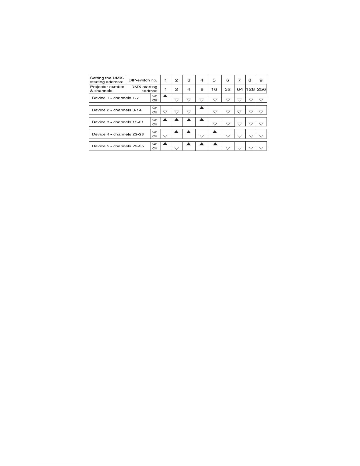
Addressing
Each device occupies 7 channels. To ensure that the control signals are properly directed to each device, the device requires
addressing. This is to be adjusted for every single device by changing the DIP-switches as set out in the table below.
The starting address is defined as the first channel from which the device will respond to the controller. Please make sure that
you do not have any overlapping channels in order to control each device correctl y and independently from an y other fixture on
the DMX data link. If two, three or more devices are addressed similarly, they will work similarly.
Occupation of the DIP-switches:
Controlling:
After having addressed all devices, you may now start operating these via your controller.
DMX PROTOCOL
Channel 1 – Red
000 – 255 0 – 100% Dimming
Channel 2 – Green
000 – 255 0 – 100% Dimming
Channel 3 – Blue
000 – 255 0 – 100% Dimming
Channel 4 – White
000 – 255 0 – 100% Dimming
Channel 5 – Strobe
000 – 010 Off
011 - 255 Flash, with increasing speed
Channel 6 – Internal Programs, Auto Mode, Sound
Control
000 – 010 No function
011 – 034 Program 1
035 – 058 Program 2
059 – 082 Program 3
083 – 106 Program 4
107 – 130 Program 5
131 – 154 Program 6
155 – 178 Program 7
179 – 202 Program 8
203 – 226 Program 9
227 – 250 Auto Mode: Internal Programs
251 – 255 Sound Controlled Mode
Channel 7 – Motor
000 – 000 No Rotation
001 – 127 Rotation, clockwise, with increasing speed
128 - 255 Rotation, counter-clockwise, with
decreasing speed
CLEANING AND MAINTENANCE
We recommend a frequent cleaning of the device. Please use a soft lint-free and moistened cloth. Never use alcohol or solvents !
There are no serviceable parts inside the device except for the fuse. Maintenance and service op erations are only to be carried
out by authorized dealers.
Replacing the fuse
If the fine-wire fuse of the device fuses, only replace the fuse by a fuse of same type and rating.
Before replacing the fuse, unplug mains lead.
Procedure:
Step 1: Take out the fuseholder under the power supply.
Step 2: Remove the old fuse from the fuseholder.
Step 3: Install the new fuse in the fuseholder.
Step 4: Replace the fuseholder in the housing and fix it.
Should you need any spare parts, please use genuine parts.
If the power supply cable of this device becomes damaged, it has to be replaced by authorized dealer s only in order to avoid
hazards.
TECHNICAL SPECIFICATIONS
Power supply: 220-250 V AC, 50-60 Hz
Power consumption: 30W
Number of DMX channels: 7
DMX-512 connection: 3-pin XLR
Beam angle: 60°
Sound-control: via built-in microphone via built-in microphone
Maximum ambient temperature Ta: 45° C
Maximum housing temperature TB (steady state): 60° C
Min.distance from flammable surfaces: 0.50 m
Min.distance to lighted object: 0.10 m
Fuse: F 1 A, 250V
Weight: 5.5 kg
Please note: Every information is subject to change without prior notice.
 Loading...