

Page 1

COD. 22.01.0129-0
OPERATORS MANUAL
THICKNESSER
by
INVICTA
Model
DGI-63D
INVICTA USA English Version
(877) 308-6423 - East
(800) 499-4682 - West
Page 2

Thicknesser
Model DGI-63D
General Instructions
As with all equipment, safety is to be a priority. The operator should understand the safety features and apply good
safety h
abits in transportation, adjustment, maintenance and operation of the machine. Practice and teach others
the safe operating procedures of this machine and help to prevent the possibility of accidents.
Safety Rules
1. FOR YOUR OWN SAFETY, READ THE INSTRUCTION MANUAL BEFORE OPERATING THE MACHIN E.
Learning the machine’s application, limitations, and specific hazards will greatly minimize the possibility of accidents and
injury.
2. WEAR EYE AND HEARING PROTECTION. AL
WAYS USE SAFETY GLASSES.
Everyday eyeglasses are NOT safety glasses. USE CERTIFIED SAFETY EQUIPMENT. Eye protection equipm
ent
should comply with ANSI Z87.1 standards. Hearing equipment should com
ply with ANSI S3.19 standards.
3. WEAR PROPER APPAREL.
Do not wear loose clothing, gloves, neckties, rings, bracelets, or other jewelry which may get caught in moving parts.
Nonslip footwear is recommended. Wear protective hair covering to contain long hair.
4.
DO NOT USE THE MACHINE IN A DANGEROUS ENVIRONMENT.
The use of power tools in damp or wet locations or in rain can cause shock or electrocution.
Keep your work area well-lit to prevent tripping or placing arms, hands, and fingers in danger.
5. MAINTAIN ALL TOOLS AND MACHINES IN PEAK CONDITION.
Keep tools sharp and clean for best and safest performance.
Follow instructions for lubricating and changing accessories.
Poorly maintained tools and machines can further damage the tool or machine and/or cause injury.
6. CHECK FOR DAMAGED PARTS.
Before using the machine, check for any damaged parts. Check for alignment of moving parts, binding of moving parts,
breakage of parts, and any other conditions that may affect its operation. A guard or any other part that is
damaged sho
uld be properly repaired or replaced.
Damaged
parts can cause further damage to the machine and/or injury.
7. KEEP THE WORK AREA CLEAN.
Cluttered areas and benches invite accidents.
8. KEEP CHILDREN AND VISITORS AWAY.
Your shop is a potentially dangerous environment. Children and visitors can be injured.
9. REDUCE THE RISK OF UNINTENTIONAL STARTING.
Make sure that the switch is in the “OFF” position before plugging in the power cord. In the event of a power failure, move
the switch to t
he “OFF” posit
ion.
An accidental start-up can cause injury.
10.
USE THE GUARDS.
Check to see that all guards are in place, secured, and working correctly to reduce the risk of injury.
11. REMOVE ADJUSTING KEYS AND WRENCHES BEFORE STARTING THE MACHINE.
Tools, scrap pieces, and other debris can be thrown at high speed, causing injury.
12. USE THE RIGHT MACHINE.
Don’t force a machine or an attachment to do a job for which it was n ot designed. Damage to the machine and/or injury
may result.
01
Page 3

Thicknesser
Model DGI-63D
02
13. USE RECOMMENDED ACCESSORIES.
The use of accessories and attachments not recommended by Delta may cause damage to the machine or injury to the
user.
14. USE THE PROPER EXTENSION CORD.
Make sure your extension cord is in good condition. When using an extension cord, be sure to use one heavy enough to
carry the current your product will draw. An undersized cord will ca
use a drop in line voltage, resulting in
loss of power
and overheating. See the Extension Cord Chart for the correct size depending on the cord length and nameplate amper e
rating. If in doubt, use the next heavier gauge. The smaller the gauge number, the heavier the cord.
15. SECURE THE WORKPIECE.
Use clamps or a vise to hold the workpiece when practical. Loss of control of a workpiece can cause injury.
16. FEED THE WORKPIECE AGAINST THE DIRECTION OF THE ROTATION OF THE BLADE, CUTTER, OR
ABRASIVE SURFACE.
Feeding it from the other direction will cause the workpiece to be thrown out at high speed.
17. DON’T FORCE THE WORKPIECE ON THE MAC HINE.
Damage to the machine and/or injury may result.
18. DON’T OVERREACH.
Loss of balance can make you fall into a working machine, causing injury.
19. NEVER STAND ON THE MACHINE.
Injury could occur if the tool tips, or if you accidentally contact the cutting tool.
20. NEVER LEAVE THE MACHINE RUNNING UNATTENDED.
TURN THE POWER OFF.
Don’t leave the machine until it comes to a complete stop. A child or visitor could be injured.
21. TURN THE MACHINE “OFF”, AND DISCONNECT THE
MACHINE FROM THE POWER SOURCE before installing or re
m
oving accessories, before adjusting or chang
ing
set-ups, or when making repairs. An accidental start-up can cause injury.
22. MAKE YOUR WORKSHOP CHILDPROOF WITH PADLOCKS, MASTER SWITCHES, OR BY REMOVING
STARTER K
EYS.
The accidental start-up
23. STAY ALERT, WATCH WHAT YOU ARE DOIN G, AND USE COMMON SENSE. DO NOT USE THE MACHINE
WHEN YOU ARE TIRED O
R UNDER THE INFLUENCE OF DRUGS, ALCOHOL, OR MEDICATION.
A moment of inattention while operating power tools may result in injury.
24. USE OF THIS TOOL CAN GENERA
TE AND DISBURSE DUST OR OTHER AIRBORNE PARTICLES,
INCLUDING WOOD DUST, CRYSTALLINE SILICA DUST AND ASBESTOS DUST.
Direct pa
rticles away from face and body. Always operate tool in well ventilated area and prov
ide for proper dust
removal. Use dust collection system wherever possible. Exposure to the dust may cause serious and permanent
respiratory or other injury, including silicosis (a seri
ous lung disease), cancer, and death. Avoid breathing the
dust, and avoid prolonged contact with dust. Allowing dust to get into your mouth or eyes, or lay on your skin
may promote absorption of harmful material. Always u
se properly fitting NIOSH/O
SHA approved respiratory
protection appropriate for the dust exposure, and wash exposed areas with soap and water.
Page 4

Thicknesser
Model DGI-63D
Additional Specific Safety Rules
1. DO NOT OPERATE THI
S MACHINE until it is completely assembled and installed according to the instructions.
A machine incorrectly assembled can cause serious injury.
2. OBTAIN ADVICE from your supervisor, instructor, or another qualified person if you are not thoroughly familiar
with the operation of this machine. Kno
wledge is safety.
3. FOLLOW ALL WIRING CODES and recommended electrical connections to prevent sho c k or electrocution.
4. KEEP KNI
VES SHARP and free from
rust an
d pitch. Dull or rust
ed kni
ves work harder and can cause kickback.
5. NEVER TURN THE MACHINE “ON”
before clearing the table of all object
s (tools, scraps of wood, etc.).
Flying debris can cause serious injury.
6. NEVER TURN THE MACHINE “ON”
with the workpiece conta
cting the cutterhead. Kickback can occur.
7. SECURE
THE MACH
INE TO A SUPPORTING SURFACE to prevent the machine from sliding, walking or
tipping over.
8. PROPERLY SECURE THE KNIVES IN THE CUTT
ERHEAD before turning the power “ON”. Loose blades may
be thrown out at high speeds causing serious injury.
9. LOCK THE SPEED SETTING SECURELY before
feeding the workpiece through the machine. Changing
speeds while planing can cause kick-back.
10. AVOID AWKW
ARD OPERATIONS AND HAND POSITIONS.
A sudden slip could cause a hand to move into the knives.
11. KEEP ARM
S, HANDS, AND FINGERS away from the cutterhe
ad, the chip exhaust opening, and the feed
rollers to prevent severe cuts.
12. NEVER REACH INTO THE CUTTERHEAD ARE
A while the machine is running. Your hands can be drawn into
the knives.
13. DO NOT STAND IN LINE OF THE WORKPIECE.
Kickbac
k can cause injury.
14. ALLOW THE
CUTTERHEAD TO REACH FULL SPEED bef
ore feeding a workpiece. Changing speeds while
planing can cause kickback.
15. WHEN PLANING BOWED STOCK, place the
concave (cup down) side of the stock on the table and cut with
the grain to prevent kickback.
16. DO NOT FEED A WORKPIECE that is wa
rped, contains knots, or is embedded with foreign objects (nails,
staples, etc.). Kickback can occur.
17. DO NOT FEED A SHORT, THIN, OR NARROW WORKPIECE INTO THE MACHINE. Your hands ca
n be
drawn into the knives and/or the workpiece can be thrown at high speed
s. See the “OPERATION” section of this
instruction manual for details.
18. DO NOT FEED A WORKPIECE int
o the outfeed end of the machine. The workpiece will be thrown out of the
opposite side at high speeds.
19. REMOVE SHAVINGS ONLY with the power “OFF”
to prevent serious injury.
03
Page 5

Thicknesser
Model DGI-63D
04
20. PROPERLY SUPPORT LONG OR WIDE WORKPIECES. Loss of control of the workpiece can cause serious
injury.
21. NEVER PERFORM LAYOUT, ASSEMBLY or set-up work on th
e table/work area when the machine is running.
Serious injury will result.
22. TURN THE MACHINE “OFF”, DISCONNECT IT FROM THE POWER SOURCE, and clean the table/work
area before
leaving the machine. LOCK THE SWITCH IN THE “OFF” POSITION to prevent unauthorized use.
Someone else might accidentally start the machine and cause injury to themselves or others.
ADDITIONAL SPECIFIC SAFETY RULES
SAVE THESE INSTRUCTIONS.
Refer to them often and use them to instruct others.
POWER CONNECTIONS
A separate electrical circuit should be used for your machines. This circuit should not be less than #12 wire and
should be protected with a 20 Amp time lag fuse. If an extension cord is used, use only 3-wire extension cords
which have 3- prong grounding type plugs and matching receptacle which will accept the machine’s plug. Before
connecting the machine to the power line, make sure the switch (s) is in the “OFF” position and be sure that the
electric current is of the same characteristics as indicated on the machine. All line connections should make good
contact. Running on low voltage will damage the machine.
DO NOT EXPOSE THE MACHINE TO RAIN OR OPERATE THE MACHINE IN DAMP LOCATION
S.
MOTOR SPECIFICATIONS
The 22-610 has a 10 HP three phase motor that comes wired at 230 volts and 60 HZ alternating current. The m otor
is also capable of being wired for 460 volt operation, but this connection must be done by a qualified electrician and
conform to the National Electric Code and all local codes and ordinances.
GROUNDING INSTRUCTIONS
These machines are not supplied with power cords and they are intended to be permanently connected to the
building’s electrical system. All wiring must be done by a qualified electrician and conform to the National Electric
Code and all local codes and ordinances. For wiring instructions, see section “ELECTRICAL CONNECTIONS” in
this manual.
FUNCTIONAL DESCRIPTION
FOREWORD
The Invicta Industrial Model DGI-63D Planer with a 10 HP, three-phase motor capable of 230 volt or 460volt
operation with an LVC magnetic starter and automatic reset overload protection; 4-knife cutterhead, infeed and
outfeed rollers, chipbreakers, dust chute, knife-setting gauge and wrench.
NOTICE: THE PHOTO ON THE MANUAL COVER ILLUSTRATES THE CURRENT PRODUCTION MODEL. ALL
OTHER ILLUSTRATIONS CONTAINED IN THE MANUAL ARE REPRESENTATIVE ONLY AND MAY NOT
DEPICT THE ACTUAL COLOR, LABELING OR ACESSORIES AND ARE INTENDED TO ILLUSTRATE
TECHNIQUE ONLY.
Page 6

Thicknesser
Model DGI-63D
CARTON CONTENTS
The planer is shipped complete in one container mounted to a shipping skid. Remove the wooden crate from
around the machi
ne. The planer is shipped with the motor, motor pulleys and belts assembled to the machine. Fig.
2, illustrates the loose items supplied with the machine.
1
1. Planer
2. Cutterhead guard
3. Dust chute
4. Knife guage
5. Open end wrenches
6. Hex wrenches
7. Gauge clock
05
2
3 4
5
6
7
Page 7
Thicknesser
Model DGI-63D
UNPACKING AND CLEANING
Carefully unpack the machine and all loose items from the shipping container(s). Remove the protective coating
from all unpainted surfaces. This coating may be removed with a soft cloth moistened with kerosene (do not use
acetone, gasoline or lacquer thinner for this purpose). After cleaning, cover the unpainted surfaces with a good
quality household floor paste wax.
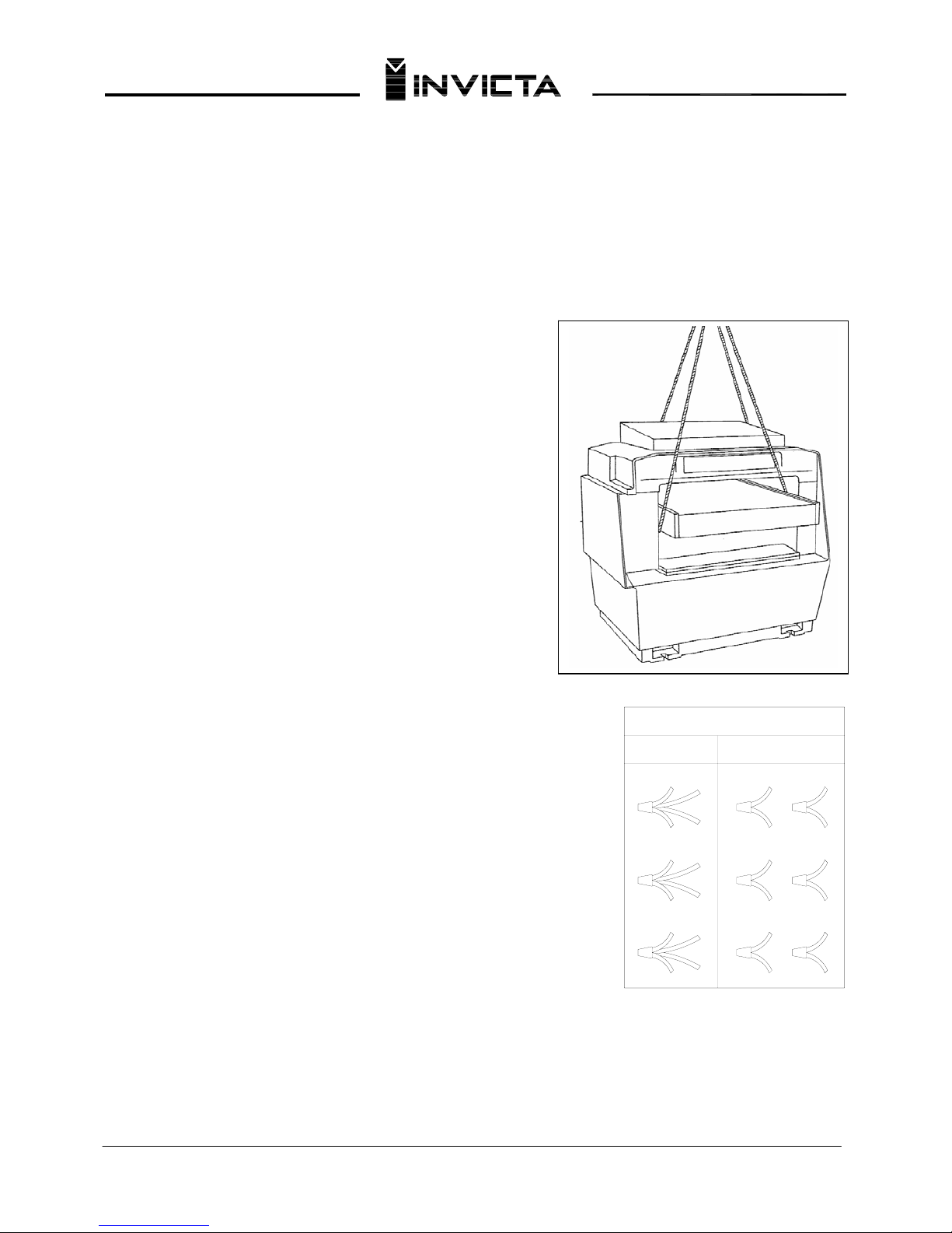
UNLOADING AND POSITIONING MACHINE
This machine should be unloaded using a crane and slings around
and under the table on both sides, as shown in Figure 2. Lift the
machine slowly, making sure it is well balanced, and lower it
carefully.
06
Using rollers or a similar hauling device, push the machine to the
desired worki
ng site. Once the machine is in position it should be
leveled and positioned on hard rubber pads placed underneath the
four corners.
Remove protective coating from the table, bed rolls, feed rolls and
cutterhead. This coating m
ay be removed with a stiff brush and/or
soft cloth moistened with kerosene (do not use acetone, gasoline or
lacquer thinner for this purpose).
WARNING CARE MUST BE TAKEN WHEN CLEANING THE
CUTTERHEAD AS THE KNIVES ARE IN THE
CUTTERHEAD AND THESE KNIVES ARE VERY SHARP.
Fig. 2
After cleaning table, cover table surface with a good quality paste
wax.
10
4
8
2
10
28
5
6
93
11
3
9
5
11
4
71
12
1
7
6
12
230 VOLT 460 VOLT
MOTOR CONNECTIONS
ELECTRICAL CONNECTIONS
Before connecting your machine to an electrical power system, make sure
the motor rating agrees with the electrical system it is to be connected to.
The 24" Planer is shipped wired for 230 volts, three phase operation.
If you desire to operate your planer at 460 volts, three pha
se operation,
refer to the Electrical Instruction Manual supplied with your planer for
detailed instructions on Changing Voftage of LVC Motor Starters. Three
STEPS must be followed when changing line voltage. These steps are as
follows:
1. Change leads in the motor junction box for the proper line voltage, as
s
hown on the motor nameplate. Refer t
o Fig. 3.
2. Move the transformer primary pigtail to the proper terminal corresponding
to the new input voltage.
Fig. 3
3. Change the heater elements in the overload block for the proper voltage/amperage rating shown on the motor
nameplate.
These three steps are clearly explained in the electrical instructions supplied with your planer.
Page 8
Thicknesser
Model DGI-63D
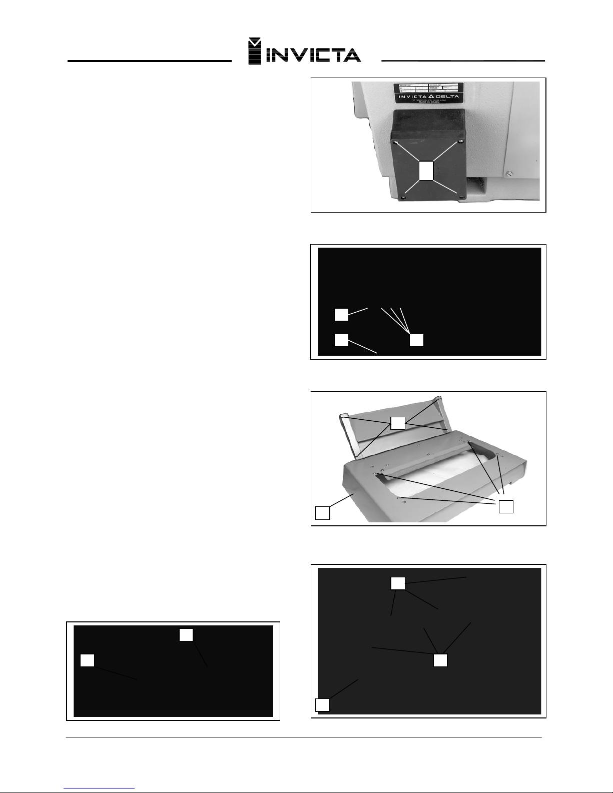
To connect power to your machine, proceed as follows
for either 200-230/460 volts, three phase operation.
07
1. Remove the four screws, one of which is shown at
(A) Fig. 4, and remove cover (B).
2. Insert power line through entrance hole (E) and
con
nect the three po
wer lines to terminals L1, L2 and
L3 (shown at C). The green ground wire should be
connected to the ground terminal (J).
3. Replace cover (B) Fig. 4.
IMPORTANT: If after the m
achine is in operation, the
cutterh
ead turns in the wrong direction, interchange any
two of the three power lines (C) that a
re connected to
terminals L1, L2 and L3.
OVERLOAD PROTECTION
Your planer is provided with overload protection which
will shutoff the motor if the planer is overloaded or if line
voltage falls below safe levels, lithe motor shuts off due
to overloading or low voltage, let the motor cool three to
five minutes.
The overload block supplied with this planer will
autom
atically re
set it
self
and
the machine can be
started again by pushing the start button. If the machine
continually shuts off due to overloading, the cause of
overloading must be corrected. If this happens, it is
recommended you obtain advice from a qualified
electrician.
ASSEMBLING CUTTERHEAD GUARD
AND DUST CHUTE
To assemble the cutterhead guard:
1. WA
RNING DISCONNECT MACHINE FROM
POWER SOURCE
2. Remo
ve four screws and washers at (A) Fig. 6.
3. Place guard on planer cover (C) so that the holes in
the guard (B) align with the holes in the cove
r (C).
4. Replace screws and washer removed in Step 1.
5. Remove three screws (E) Fig. 7 on planer cover (C).
6. Place dust chute on cover so that the holes in the
dust chute (D) align with the holes in the cover (C).
7. Repla
ce the screws and washers removed in Step 5.
8. The cutterhead guard (B) Fig. 7A and dust chute (D)
Fig. 7A shoul
d be arranged as shown in Fig. 7A
Fig. 4
A
Fig. 5
J
Fig. 6
Fig. 7
Fig. 7A
BE
B
A
C
D
C
E B
D
Page 9
Thicknesser
Model DGI-63D
OPERATIONAL CONTROLS AND ADJUSTMENTS
STARTING AND STOPPING THE PLANER
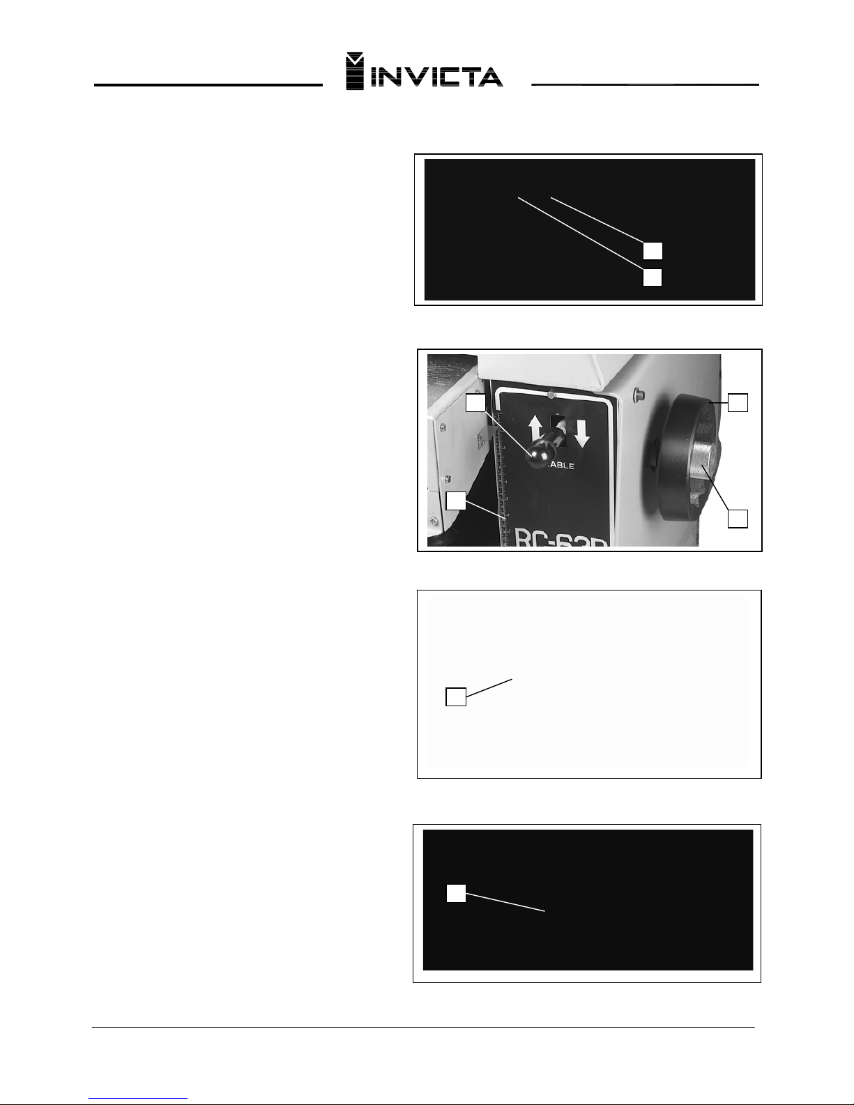
The machine is started by pressing the green
(shrouded)
"ON" button
(A) and stopped by pressing the red
(mushroom type) "OFF" b
utton (B), as shown in Fig.
8.
TABLE RAISING AND LOWERING
CONTROLS
WARNING DISCONNECT MACHINE FROM
POWER SOURCE
For fast easy changes in thickness settings to
accommodate thick or thin
stock, the table can be
rapidly raised or lowered by pulling up or pushing
down on the table raising and lowering control lever
(C) Fig. 9. NOTE: The machine must be turned "ON"
and the feed rolls engaged when doing this. Fine
adjustment of the table height can be made by
loosening lock knob (D) Fig. 9, and turning table
raising and lowering handwheel (E). Tighten lock
knob (D) after table adjustment is made. The handy
English/Metric Scale (F) indicates the desired table
height setting. The English/Metric scale and shelf (G)
Fig. 10, located on the front of the table is used to
quickly determine the thickness of stock, before or
after planing, by simply placing the stock on the shelf
as shown in Fig. 10. This enables you to quickly
position the table for the next cut.
NOTE: The setting of the table to its final position
should
always be made by rai
sing the table to the desired
setting and not lowering the table. T
his insures that
all backlash will be removed from the raising and
lowering screws.
FEED ROLL SPEED CONTROLS
Your planer is supplied with feed roll speeds of 25
and 46 feet per minute. When the feed roll lever (A
)
is in the "up" position as shown in Fig. 11, the feed
rolls are engaged and the planer will feed. When the
lever (A) is in the "down" position the feed rolls are
disengaged and the planer will not feed. To
disenguage the feed rolls, at any time, simply push
down on the engagement lever (A) Fig. 11.
Fig. 8
Fig. 9
Fig. 10
B
A
EC
F
G
A
D
Fig. 11
08
Page 10
Thicknesser
Model DGI-63D
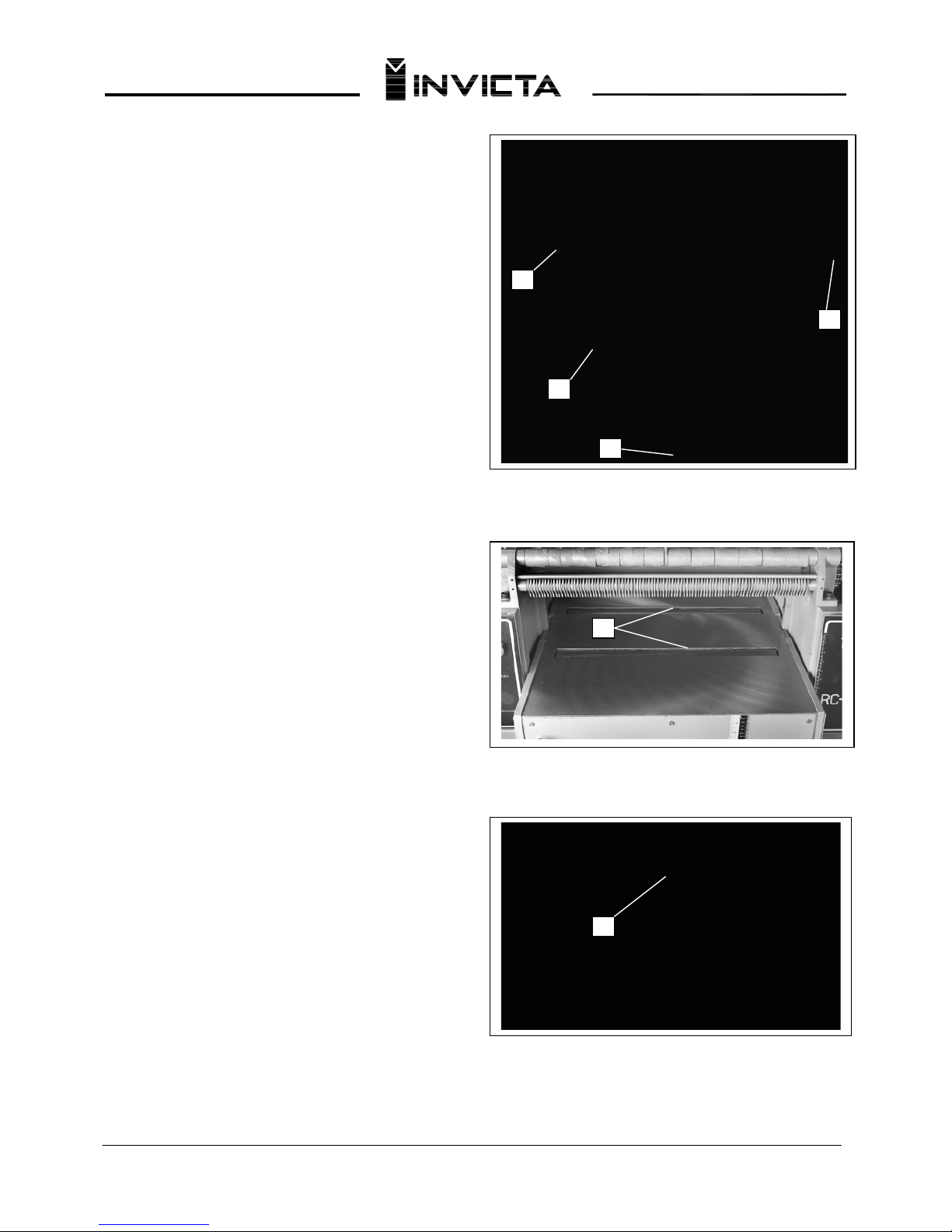
To change feed roll speeds, make sure the feed roll
engagement lever (A
) Fig. 12, is disengaged (in the
down position) and open the left side door of the
machine. When the belt (C) is on the smallest step of the
motor pulley (D) and the largest step of the gearbox
pulley (E), the feed roll speed will be 25 feet per minute.
When the belt (C) is on the largest step of the motor
pulley (D) and the smallest step of the gearbox pulley
(E), the feed roll speed will be 46 feet per minute.
TABLE ROLLERS
Your planer is supplied with two table rollers (A) Fig. 13,
which aid in feeding the stock by reducing friction and
turn as the
stock is fed through the planer. It is
not
possible to give exact dimensions on the proper height
setting of the table rollers because each type of wood
behaves differently. As a general rule, however, when
planing rough stock the table rollers should be set HIGH
and when planing smooth stock the table rollers should
be set LOW.
To raise the table rollers (A) Fig. 13, turn adjustment
knob (B) cloc
kwise. To lower table rollers (A) turn
adjustment knob (B) counterclockwise.
ANTI-KICKBACK FINGERS
Anti-kickback fingers (A) Fig. 14, are provided on your
planer to prevent kickback. Th
ese fingers operate by
gravity and it is necessary to inspect them occasionally
to make sure they are free of gum and pitch so they
move independently and operate correctly.
Fig. 12
Fig. 13
C
D
AAA
E
Fig. 14
09
Page 11
Thicknesser
Model DGI-63D
Fig. 16
Fig. 17
F
A
B
D
E
C
H G H B
CHECKING AND ADJUSTING BELT
TENSION
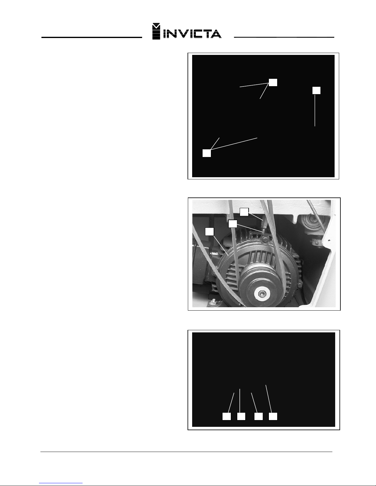
DRIVE BELT TENSION: Proper drive belt tension is
obtained when there is zero deflection, using light
finger pressure, on drive belts (A) Fig. 16, midway
between pulleys.
If an adjustment is necessary, push down on lever
(B) Fig. 16, to disenguage feed roller.
Loosen jam
nut (C) Fig. 17, located on top of motor (D) and turn
adjustment
stud (E) right or left as needed until proper drive belt
tension is obtained. Tighten jam nut (C) afte
r
adjustment is made.
FEED ROLL BELT TENSION: Proper tension on
feed roll belt
(F) Fig. 16, is obtained when there is
approximately 1" deflection, using light finger
pressure on feed roll belt (F), midway between
pulleys. If an adjustment is necessary, change
position of rod (B) Fig. 18, in stud (G) by tightening
and loosening two nuts (H) until correct belt tension
is obtained. Both nuts (H) should be tight against
stud (G) as shown in Fig. 18, after adjustment is
made.
Fig. 18
10
Page 12
Thicknesser
Model DGI-63D
11
CHECKING, ADJUSTING AND
REPLACING KNIVES
1. When checking, adjusting or replacing the
cutterhead knives on the planer, proceed as
follows:
E
B
A. WARNING DISCONNECT MACHINE FROM
POWER SOURCE
B. Remove the top cover of the planer exposing the
cutterhead.
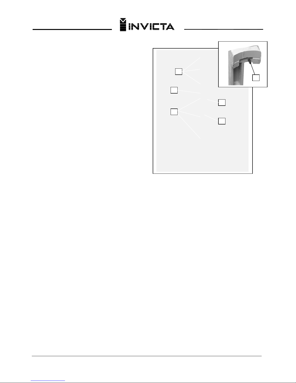
C. Check all four knives for proper setting using the
knife guage (A), as shown in Fig. 20. When the gu
age
(A) is placed on the cutterhead and the bottom of the
two roll pins, one of which is shown at (B), are against
the edge of the slot (C) opposite the knife, the knife
should just contact the bottom of the guage (D).
D. If any of the knives require an adjustment, slightly
loosen the knife locking bar of ea
ch of the four knives
by turning the knife locking screws (E) Fig. 20, into the
locking bar just enough to relieve stress in the
cutterhead but not disturb the setting of the four
knives.
E. To adjust the knife that must be reset, loosen all of
that knife's locking
screws (E) Fig. 20, by turning them
into the locking bar. As the knife locking bar becomes
loose, lifter springs under the knife will raise the knife
until it contacts the bottom of the guage (D). Then
snug up the knife locking bar by lightly backing out the
locking screws (E) against the knife slot.
IMPORTANT: AT THIS TIME, ONLY TIGHTEN THE
KNIFE INTO THE SLOT ENOUGH TO HOLD IT IN
POSITION. F. If additional knives must be reset,
repeat STEP C.
G. After all four knives are set with the screws just
snu
g, back out and tighte
n the locking screws, five of
which are shown at (E) Fig. 20, against the slot. Start
with the end screws first and proceed on alternate
sides toward the center screws until the knife is
securely held in the cutterhead. Tighten the remaining
three knives in the same manner.
2. WARNING IF THE KNIVES ARE TO BE
REMOVED FOR SHARPENING OR
REPLACEM
ENT, EXTREME CARE SHOULD BE
TAKEN AS THE KNIVES ARE VERY SHARP. TO
REMOVE THE KNIVES, WEAR GLOVES AND
PROCEED AS FOLLOWS:
A. WARNING DISCONNECT MACHINE FROM
POWER SOURCE
B. To remove each knife, loosen the knife locking
bar, by turning the locking screws, five of which are
shown at (E) Fig. 20, into the knife locking bar and
remove the locking bar, knife and springs located
under the knife.
C. Remove the remaining three knives in the same
m
anner.
D. Thorough
ly clean the knife slots, knife bars,
springs and scre
ws. If the threads appear worn or
stripped or if the heads are becoming rounded,
replace them.
E. Inspect the cutting edge of the knives for nicks or
wire
ed
ge.
Hone th
e
knives slightly using a stone or
if the knives are to be sharpened, maintain a cutting
angle of 40 degrees.
F. Insert springs, knives and knife locking bars into
all four slot
s in the cutterh
ead. Push knive
s down as
far as possible and back out locking screws, five of
which are shown at (E) Fig. 20, just enough to hold
all four knives in the cutterhead.
G. Adjust all four knives as explained in Step 1.
Fig. 20
C
A
E
D
Page 13
Thicknesser
Model DGI-63D
Fig. 21
Fig. 22
AB A
C
A
B
B
A
12
LEVELING THE TABLE
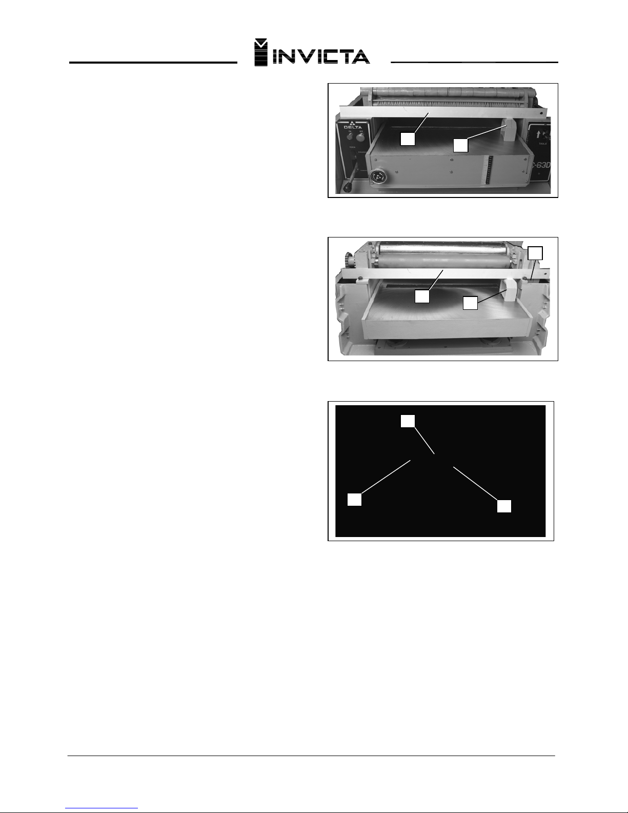
The table must be parallel to the cutterhead knives. To
check and adjust, proceed as follows:
1. WA
RNING DISCONNECT MA
CHINE FROM
POWER SOURCE
2. Remove the four screws that attach the top cover to
the planer and carefully remove the top cover.
3. Place a straight edge (A) Fig. 21, on the ground
surfa
ces (B
) of the planer, as shown.
4. Place the guage block (C) Fig. 21, on the table
directly underneath the straight ed
ge at one side, as
shown, Raise the table until the guage block just
touches the straight edge. Do not raise or lower the
table any further until the adjustment for leveling the
table is completed.
5. Move the guage block (C) Fig. 21, to the opposite
(left end) of the table and check to see if the table is
the sam
e distance from the straight edge as on the
right side.
6. Place the straight edge (A) on the two ground
surfaces (B
) of the outfeed end of the planer as shown
in Fig. 22. Check both ends of the table with guage
block (C) to see if table is level.
7. If the table is low or high at any of the four points
checked
with
the g
uage block in Figs. 21 and 22,
locate the post directly underneath the end of the table
that must be adjusted. Then loosen the three screws,
two of which are shown at (A) Fig. 22A, and turn flange
(B) to raise or lower the table at that end.
Fig. 22A
Page 14
Thicknesser
Model DGI-63D
13
CHECKING AND ADJUSTING
BED ROLL HEIGHT
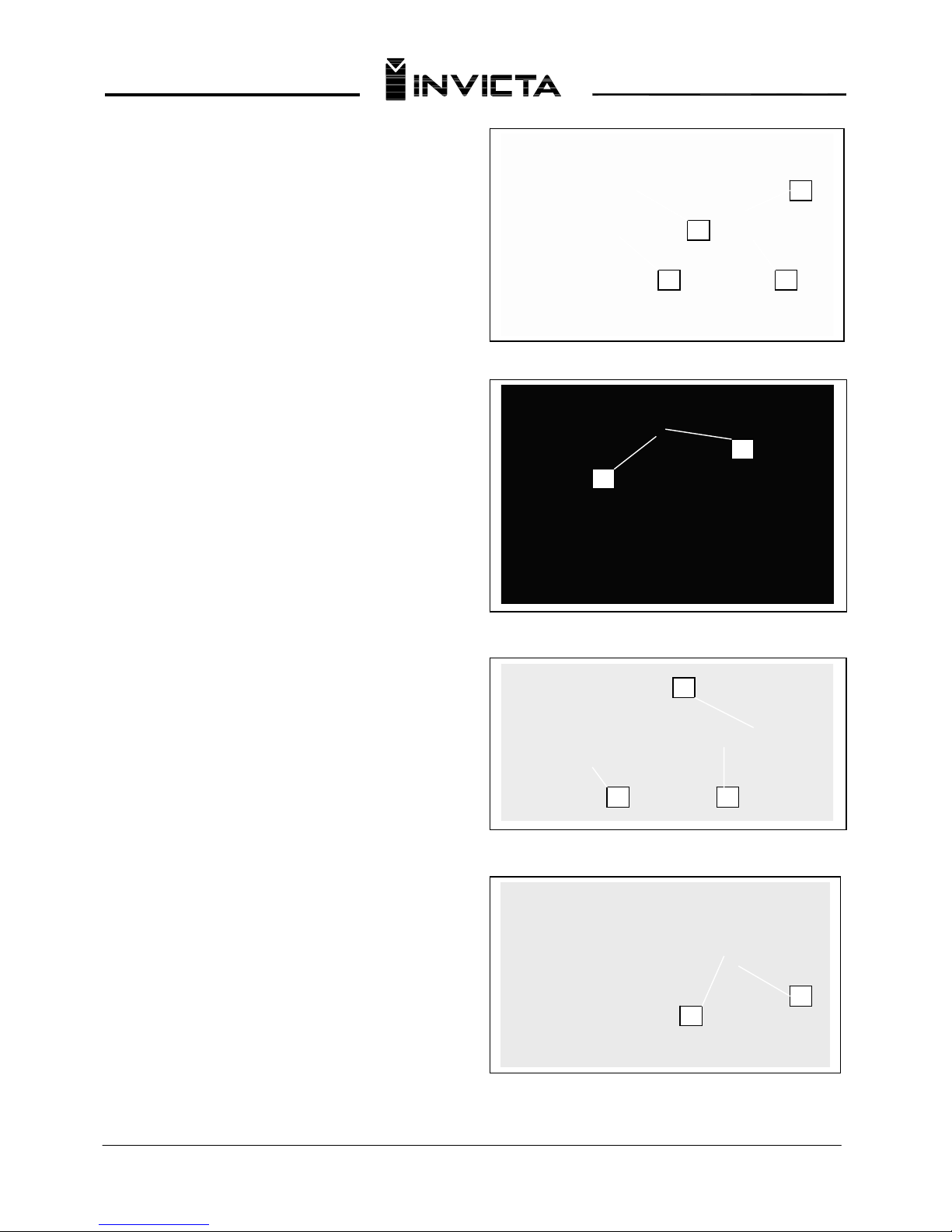
The height of the bed rolls (A) and (E) Fig. 23A, should
be set between .002" and .004" above the table
surfac
e, with the bed rolls at their lowest position. To
check the infeed bed roller height setting, proceed as
follows:
1. DISCO
NNECT MACHINE FROM POWER SOURCE
2. Turn
height adju
stment knob
(B), counterclockwi
se
as far as it will go.
3. Place a straight edge (C), across the infeed and
outfeed rollers on the left side of the table as shown.
4. With a fee
ler guage (D), measure the gap between
the table surface and the straight edge (C) ne
ar the
infeed roll (E).
5. If an adjustment to the infeed roller (E), is necessary,
loosen set screw (F) Fig. 23B, located underneath the
left front end of the table.
6. Turn adjustment collar (G) Fig. 23B left or right as
needed to attain proper
height adjustment.
7. Tighten set screw (F) Fig. 23B after adjustment is
made.
To check the outfeed roller height s
etting, proceed
as follows:
1. With a feeler guage (H) Fig. 23C, measure the gap
betwe
en the table surface and the st
raight edge (C)
near the outfeed roller (E).
2. If an adjustment to the outfeed roller is necessary,
loosen jam nut (K) Fig. 23
0, located on the left side of
machine under the table, and turn collar (L) right or left
as needed until the outfeed roller is adjusted properly.
3. Tighten jam nut (K) Fig. 23D.
Fig. 23A
Fig. 23B
Fig. 23C
D
A
E
C
F
G
C
H E
L
K
Fig. 23D
Page 15
Thicknesser
Model DGI-63D
14
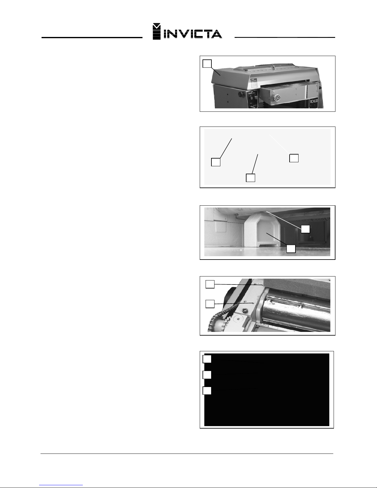
ADJUSTING PRESSURE BAR
IMPORTANT: THE PRESSURE BAR IS SET AT THE
FACTORY AND SHOULD NOT NEED ASJUSTMENT.
BUT WHEN KNIVES ARE SHARPENED OR
REPLACED THE PRESSURE BAR SETTING
SHOULD BE CHECKED AND ADJUSTED IF
NECESSARY.
The pressure bar is located directly behind the
cutterhead and rides on the plan
ed surface of the stock,
p
ressing the stock down on the table. If the stock does
not feed, the pressure bar is set too low. If the stock has
chatter marks, the pressure bar is set too high. The
p
ressure bar must be parallel to the knives and set .040"
below the cutting circle. To check and adjust the
pressure bar, proceed as follows:
1. WARNING DISCONNE
CT MACHINE FROM
POWER SOURCE
2. Remove the four screws that attach the top cover (A)
Fig. 24A to the planer and carefully remove the top
cover.
3. Make certain the knives a
re adjusted properly as
p
reviously explained under CHECKING, ADJUSTING
AND REPLACING KNIVES.
4. Place the guage block (A) Fig. 24B, on the table
directly under
neath the cutterhead as shown. Place a
.040" feeler guage (B) Fig. 24B, on top of the guage
block and raise the table until the knife (C) just touches
the feeler guage when the knife is at its lowest point.
5. Next, set the feeler guage aside and move the guage
block (A) Fig
. 25, directly underneath the pre
ssure bar
(B) on one end of the table. The pressure bar (B) should
j
ust touch the guage block (A). Check the pressure bar
at the opposite end of the table in the same manner.
6. If the pressure bar must be adjusted, remove screw
(D) Fig. 26. Loosen scre
w (E) Fig. 26A, three or four
turns. Turn screw (F) Fig. 26A clockwise to raise the bar
or counter clockwise to lower the bar. The bottom of
p
ressure bar should just touc h the gauge block (A) Fig.
25.
8. Then tighten screw (E) Fig. 26A until it bottoms and
then loosen it
two complete turns. Replace screw (D)
Fig. 26A.
9. This adjustment to the pressure bar should be made
on the opposite end of the planer In the sam
e manner.
Fig. 24A
Fig. 23B
B
A
C
A
B
A
Fig. 25
Fig. 26
D
E
F
D
E
Fig. 26A
Page 16
Thicknesser
Model DGI-63D
15
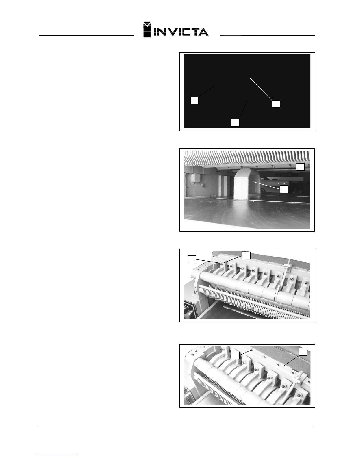
ADJUSTING THE CHIPBREAKER
The chipbreaker is located on the top of the planer
and extends down around the front of the
cutterhead. The chip-breaker segments raise as
stock is fed through and "break or curl" the chips
the same as the plane iron cap on a hand plane.
The bottom of the chipbreaker must be parallel to
the knives and set .040" below the cutting circle.
To check and adjust the chipbreaker, proceed as
follows:
1. WARNING DISCONNECT
MACHINE FROM
POWER SOURCE
2. Remove the four screws that attach the top
cover to the planer an
d carefully remove the top
cover.
3 Make certain the knives are adjusted properly as
p
reviously explained under CHECKING,
ADJUSTING AND REPLACING KNIVES.
4. Place the guage block (A) Fig. 29, on the table
directly underneath the cutterhead as shown. To
adjust the chipbreaker, place a .040" feeler gauge
(B) Fig. 29, on top of the guage block and raise the
table until the knife (C) just touches the feeler
guage when the knife is at its lowest point.
5. Move the guage block (A) Fig. 30, underneath
each chipbreaker segm
ent (B) as shown. The
bottom of each chipbreaker segment should just
touch the top of the guage block.
6. If an adjustment to any of the chipbreaker
segm
ents is necessa
ry, lo
osen the corresponding
lock nut, such as (C) Fig. 31, and turn adjusting
screw (D) in or out as required. Then tighten lock
nut (C).
7. Spring tension on the chipbrea
ker segments is
properl
y set when the head of corresponding
screw (E) Fig. 32, is two complete turns below
surface of casting (F).
Fig. 29
Fig. 30
Fig. 31
B
A
C
A
B
C
E
F
D
Fig. 32
Page 17
Thicknesser
Model DGI-63D
05
ADJUSTING SPRING TENSION ON
FEED ROLLERS
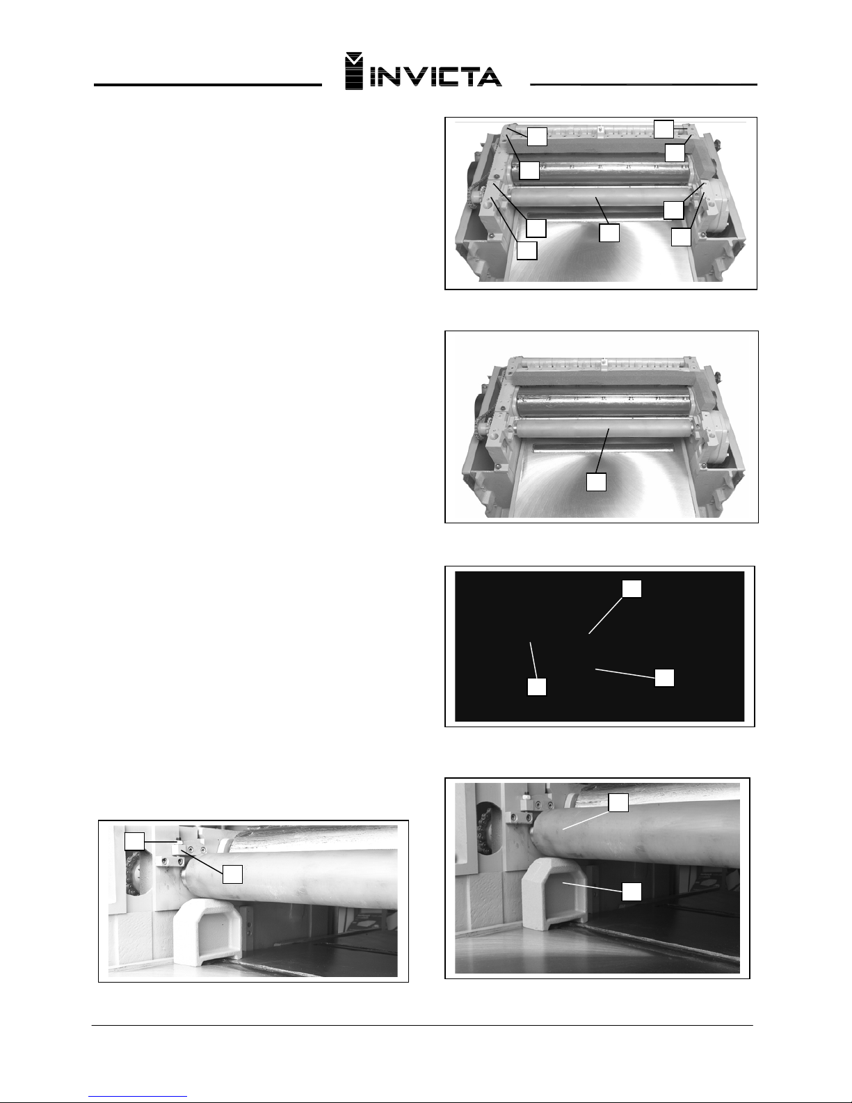
The outfeed roll (A) Fig. 33, and infeed roll (not visible)
are those parts of your planer that feed the stock while
it is being planed. The feed rolls are under spring
tension and this tension must be sufficient to feed the
stock uniformly through the planer without slipping but
should not be too tight that it causes damage to the
board. The tension should be equal at both ends of
each roll. To adjust spring tension on the infeed roll,
turn screws (B) Fig. 33, right or left until they are flush
with top of casting (C). To adjust spring tension on the
outfeed roll (A), turn screws (D) until they are 2 to 3
complete turns below surface of casting (E).
ADJUSTING OUTFEED ROLLER
The outfeed roller (A) Fig. 34, should be .035" below
the cutting circle. To check and adjust the outfeed roll,
proceed as follows:
1. WARNING DISCONNECT MA
CHINE FROM
POWER SOURCE
2. Make certain the knives are adjusted properly as
previously explained under CHECKING,] ADJUSTING]
AND REPLA
CING KNIVES.
3. Place the
guage block (C) Fig. 35, on the table
directly underneath the cutterhead, as shown. Place
a
.035" feeler guage (B) on top of the guage block and
raise the table until the knife (A) just touches the feeler
guage when the knife is at its lowest point. Do not
move the table any further until the adjustment is
completed.
4. Place the guage block underneath outfeed roll (A)
Fig. 36. The feed roll sho
uld just touch the top of the
guage block (C) which would be .035" below the cutting
circle. If a
n ad
justment is necessary, loosen locknut (D)
Fig. 37, and turn adjusting screw (E) until the outfeed
roll just touches the top of the guage block. Repeat at
opposite end of feed roll.
A
C
B
C
B
E
D
D
E
A
C
A
Fig. 33
Fig. 34
B
Fig. 35
A
C
E
D
Fig. 36
Fig. 37
Page 18
Thicknesser
Model DGI-63D
Fig. 38
17
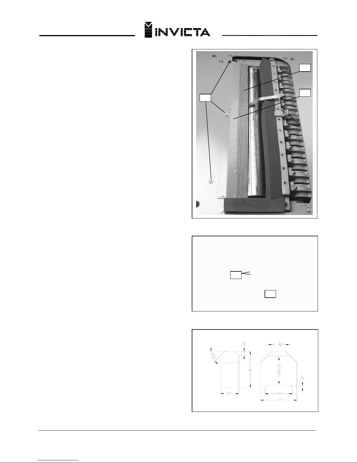
ADJUSTING CHIP DEFLECTOR
1. WARNING DISCONNECT MACHINE FROM
POWER SOURCE
2. Remove the cutterhead guard.
3. The edge (C) of the chip deflector (A) Fig.
38, should be adjusted so it is a minimum of
.040" and a maximum] of .080" away from the
cutting circle. Place a feeler gauge between the knife
and the edge of the chip deflector as shown in Fig. 38.
If an adjustment is necessary, loosen three screws (B)
and move chip deflector.
ADJUSTING TABLE HEIGHT SCALE
The table height scale is adjusted at the factory to
indicate the distance from the table to the cutting ci
rcle
(depth of cut).
To check and adjust the pointer, proceed as follows:
1. Run a piece of wood part
way through the
planer
and stop the machine.
2. Measure the thickness of the finished piece. If
necessary, loosen two screws (A) Fig.
39 adjust pointer
(B) and retighten screws (A).
GAUGE BLOCK
A gauge block has been supplied with your planer;
however, if it is ever necessary to make a gauge block
out of hardwood, follow the instructions shown in Fig.
40.
Fig. 39
Fig. 40
Page 19
Thicknesser
Model DGI-63D
MACHINE USE
When using your machine, follow these few simple steps for achie
ving the best results.
1. True Up O
ne Face – Feed one face o
f the board over a jointer, making thin cuts with each pass, until the entire
surface is flat.
2. Plane to
Thickness – Place th
e side you planed in STEP 1 face down and feed the board through the planer.
Plane until this side is flat, then plane both sides of the board until you are satisfied with the thickness. Make thin
cuts, and alternate sides with each pass. If, during the planing operation, you notice the board twisting, warping, or
bowing, repeat STEP 1 and true up one face.
3. When planing long stock, provide table extensions to support the infeed and outfeed end of
the workpiece.
4. Plane with the grain only, and keep planer table clean. Occa
sionally, wa
x the table surface to reduce friction
during the planing operation.
5. Cross-cut to Final Length – Cross-cut lumber to final length.
CAUTION: THE KNIVES ON THE PLANER WILL NOT WEAR EVENLY IF THE WOOD IS FED THROUGH
THE SAME SPOT ON THE TABLE EVERY TIME. FEED THE WOOD THROUGH THE PLANER AT DIFFERENT
SPOTS ON THE TABLE TO HELP ELIMINATE UNEVEN WEAR OF THE KNIVES.
18
LUBRICATION
Your machine requires lubrication as follows:
1. The four grease fittings, one of which is shown at (A)
Fig. 41, locat
ed at the base of the four table posts are to
be lubri
cated every 100 hours of operation with an
automotive type lithium grease o
r equivalent.
2. As required, lubricate the four table raising and
lowe
ring screws, three of which are shown at (B) Fig.
42, with an automotive type lithium grease or equivalent.
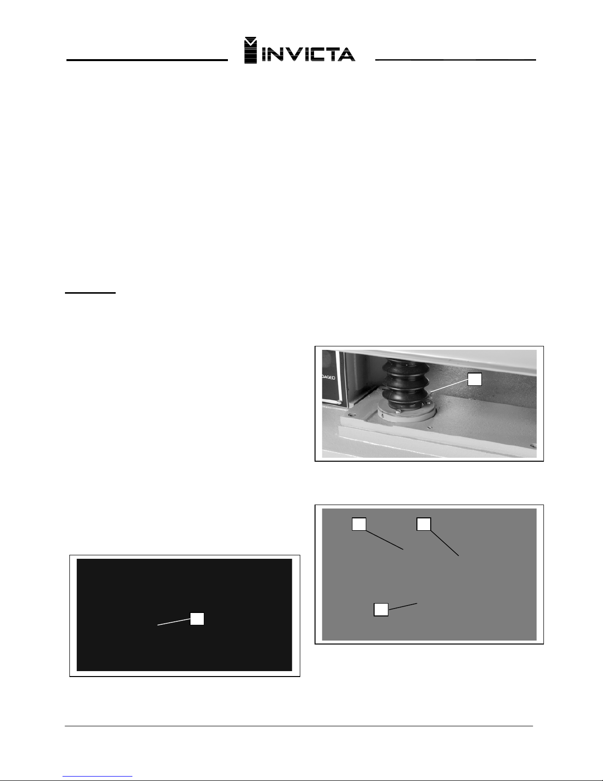
3. The gear box oil should be changed once a year
using extreme pressure g
ear oil, available from INVICTA
The gear box drain plug is shown at (C) Fig. 43. The oil
fill screw is shown at (B) and the oil level indicator is
shown at (A) Fig. 43.
Fig. 41
A B
C
B
A
Fig. 43
Fig. 42
Page 20
Thicknesser
Model DGI-63D
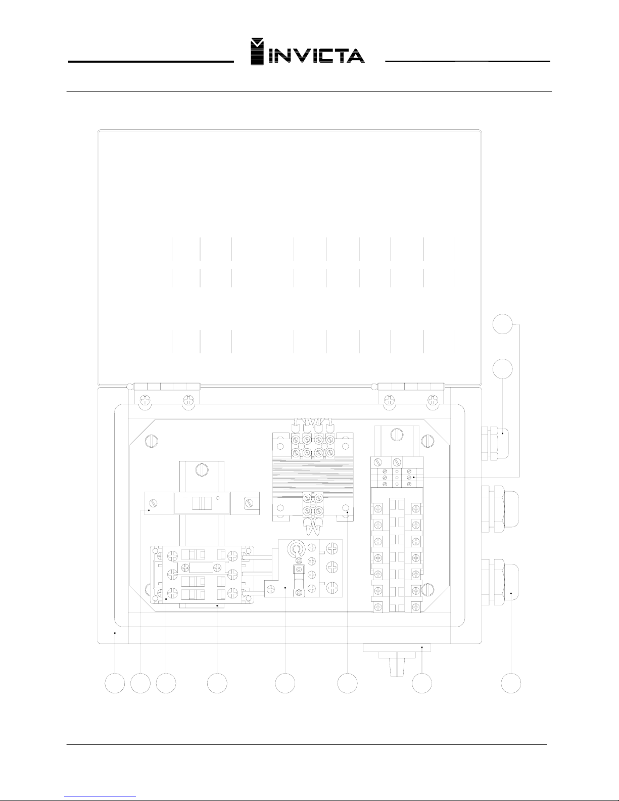
ELECTRICAL BOX
7
1
020103
04
A1
1 L1
A1
1- 2-
2 T1
05
06
A2
96 NC
PART. N°
11-28-00230
11-34-00120
11-07-00690
11-31-00070
8NAE-K205-0
11-20-00090
3 L2
A2
5 L3
3
NO
4NO
3-
4 T2
4-
6 T3
A2
95 NC97 NO98 NO
5
6
2
1
ITEM
3
4
1
3
2
4
5
6
Single phase transformer
NAME
Electrical box
Disjuntor C6A 5SX1-1
Contactor CWM25
1
QTY.
1
1
Track
Overload relay RW27D
1
2
1
07
12
56
08
11-03-00150
11-03-00090
11-02-00490
910
13 14
17 18
21 22
25 26
879
8
9
09
Press cable PG13.5
Press cable PG21
Borne terminal
2
1
1
10
10
11-04-00750
Switch electrical
19
Page 21
Thicknesser
Mod. DGI-63D
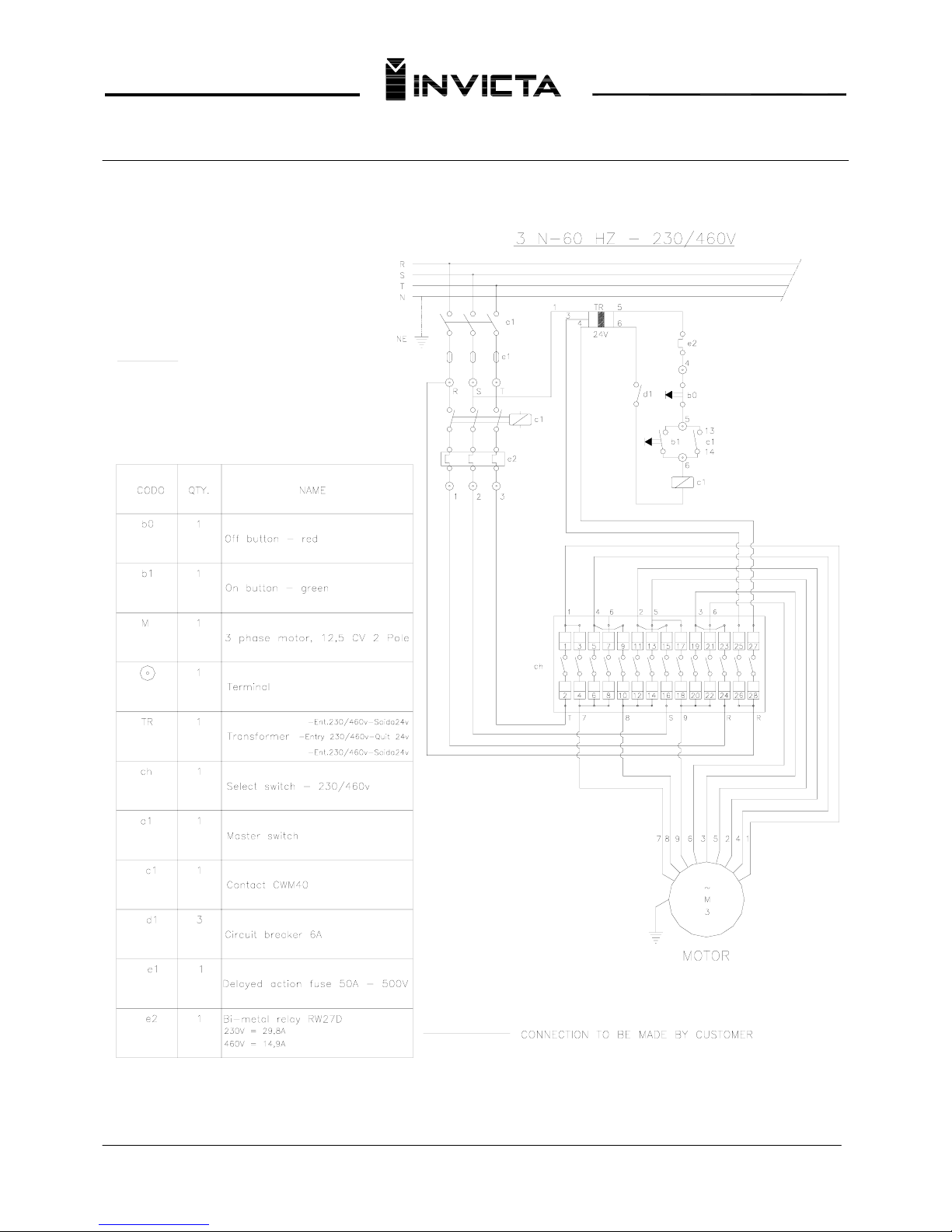
Select Switch – 230 / 460 V
IMPORTANT
SELECT THE VOLTAGE (230/460V) OF YOUR
INTERNAL ELECTRIC NETWORK.
THE VOLTAGE SELECTION KEY IS LOCATED ON
THE ELECTRICAL BOX.
FOR YOU SAFETY THE VOLTAGE SELECTION
KEY IS ON NEUTRAL POSITION.
20
Page 22
Thicknesser
Model DGI-63D
21
30
31
34
32
33
35
36
39
43
42
07
50
51
52
44
47
48
52
49
53
51
46
45
21
01
09
03
05
02
14
13
28
29
12
26
24
25
23
08
11
10
06
74
16
07
22
20
17
18
15
57
04
71
57
32
38
56
37
59
58
61
62
68
66
35
67
35
63
16
55
05
54
60
35
36
73
64
69
69
70
65
72
19
40
41
27
111
Page 23
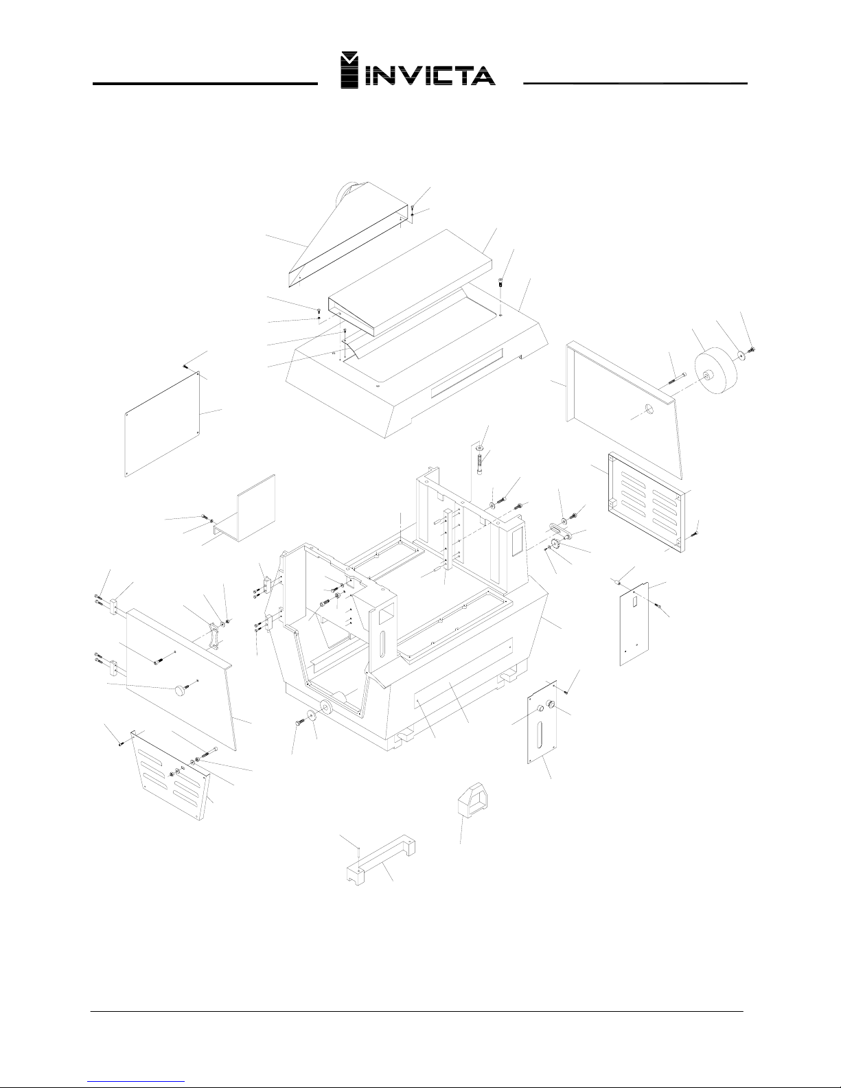
Thicknesser
Model DGI-63D
124
116
118
105
118
75
76
77
76
77
80
81
82
79
79
78
83
84
85
86
87
88
89
90
91
92
93
94
95
96
76
97
98
99
100
101
102
103
104
105
106
107
108
109
110
111
110
92
90
112
115
116
117
118
119
120
121
122
123
124
125
126
127
128
129
130
131
132
117
22
Page 24
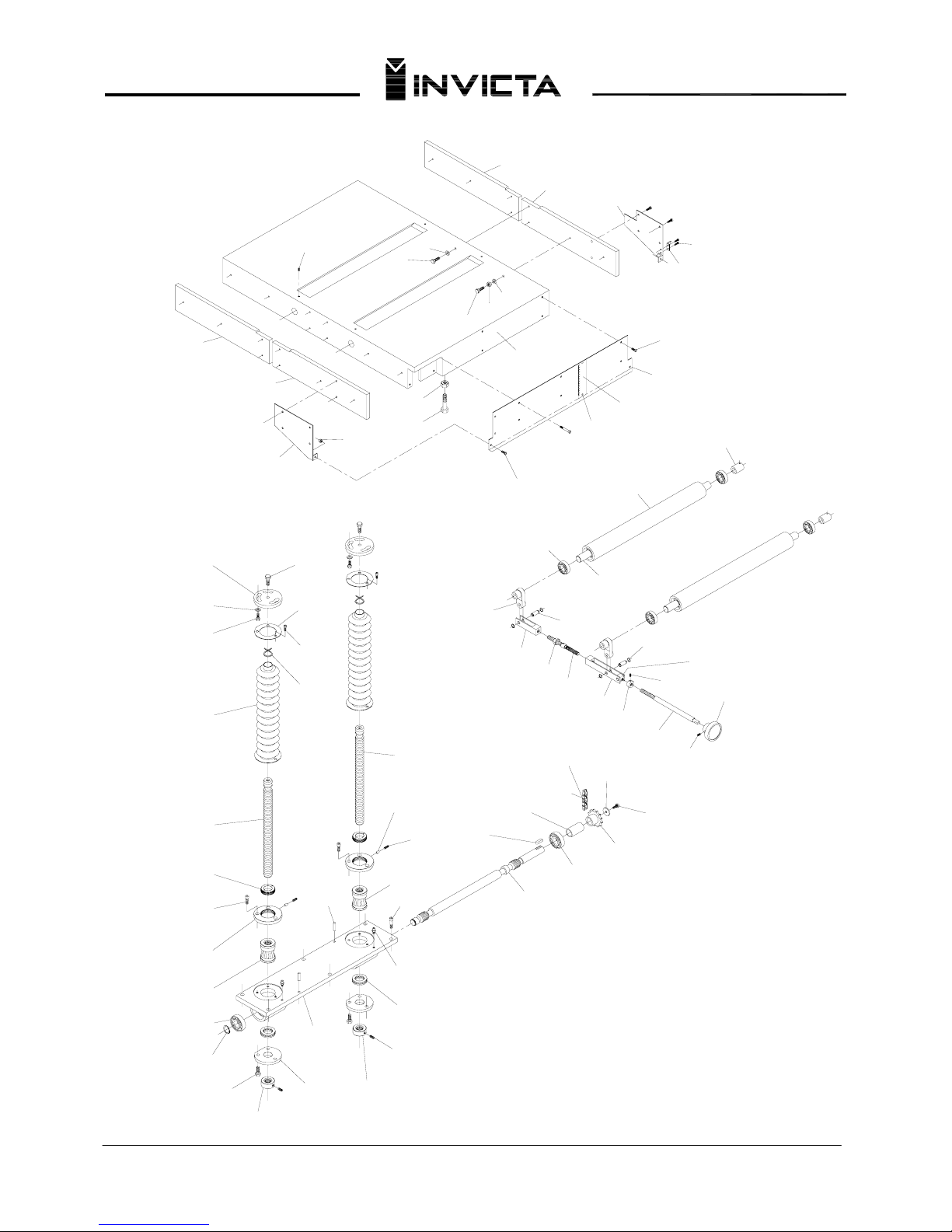
Thicknesser
Model DGI-63D
23
180
196
189
187
185
184
182
178
176
177
183
186 190
188
191
192
193
181
236
195
199
174
173
170
169
168
145
179
175
172
135
201
197
200
191
198
171
167
146
144
147
155
158
157
149
187
136
156
159
425
424
423
165
198
166
153
152
154
162
164
305
161
142
133
134
143
427
137
141
138
140
151
150
426
194
138
139
148
Page 25
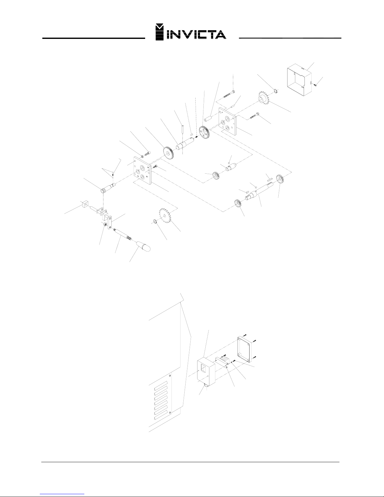
Thicknesser
Model DGI-63D
202
203
204
205
207
208
209
213
214
215
216
217
218
219
220
221
222
223
224
225
226
227
229
232
233
234
235
236
229
237
230
231
230
210
206
211
212
24
228
238
239
240
241
242
Page 26
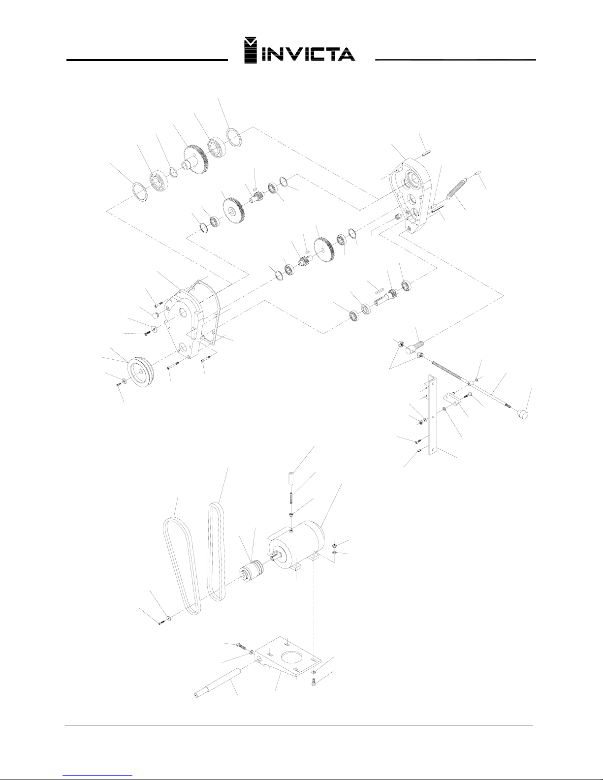
Thicknesser
Model DGI-63D
417
243
244
245
246
247
245
249
250
251
252
253
254
255
256
257
258
259
255
256
260
258
259
256
255
256
261
262
263
264
265
266
267
268
269
270
271
272
273
274
275
276
277
278
279
280
281
282
283
284
285
286
287
288
289
290
291
292
293
294
295
296
297
298
299
300
301
302
303
304
290
292
278
256
255
25
Page 27

Thicknesser
Model DGI-63D
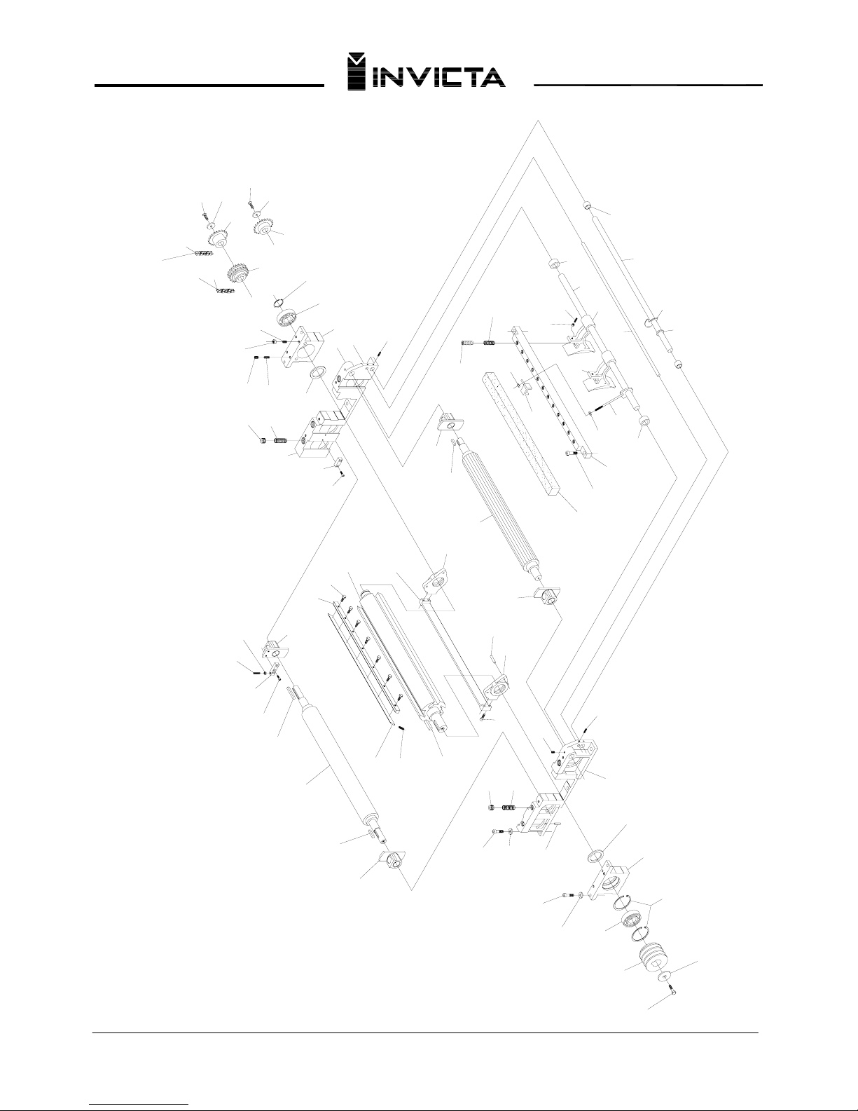
Replacement Parts
FIG. CODE QTY. NAME FIG. CODE QTY. NAME
01.… 06-04-0100-0 01… Hex head cap screw M12x1,75x35
36… 88DS-K173-0 01… Right hand bearing
02.… 84DS-K100-0 01… Cutter head washer 37… 8NCV-K311-0 01… Key
03.… 84DS-KK20-0 01… Cutter head pulley 38… 88DS-K143-0 01… Stop bumper
04.… 06-18-0026-0 02… Spring ring 39… 89DS-KK11-0 01… Right hand side
05.… 03-00-0077-0 01… Bearing 6208-2RS 40… 07-00-0035-0 03… Spring 8NMO-KK70-0
06.… 84DS-K208-0 01… Left hand bearing 41… 84DS-KK80-0 03… Spring adjustment nut
07.… 84DS-K209-0 01… O´ring 42… 07-01-0031-0 02… Spring 84DS-KK89-0
08.… 06-03-0063-0 02… Allen screw with head M10x1,5x35 43… 84DS-K177-0 02… Pressure bar screw
09.… 06-13-0023-0 02… Lock washer Ø10mm 44… 06-02-0088-0 04… Allen screw without head M10x1,5x10
10.... 26-03-0003-0 02... Pin elastic Ø8x36mm
45… 84DS-KK56-0 01… W
asher
11.… 06-13-
0034-0 03… Lock washer Ø13x2,5 46… 06-06-0034-0 01… Flat head screw M8x1,25x25
12.… 06-03-0099-0 03… Allen screw with head M12x1,75x35 47… 8NCO-KK25-0 01… Chain
13.… 87DS-K159-0 03… Spring adjustment nut 48… 16-23-0005-0 01… ISO-083 Chain junction
14.… 06-02-0060-0 01… Allen screw without head
M8x1,25x16 49… 89DS-KK51-0 01… Gear
15.… 06-02-0042-0 02… Allen screw without head M6x1x12 50… 88DS-K165-0
01… 2
nd
. Roller gear
16.… 89DS-KK10-0 01… Left hand side 51… 8NCO-KK26-0 01… Chain
17.… 06-03-0065-0 04… Allen screw with head M8x1,25x2
5 52… 16-23-0002-0 01… ASA-40 Chain junction
18… 84DS-K211
-0 01… Left hand pressure bar support 53… 88DS-K164-0 01… 1
st
. Roller gear
19.… 84DS-K180-0 02… Pressure bar pin 54… 06-18-0014-0 01… E-40 Spring ring
20.… 84DS-K130-0 01… Pressure bar blade 55… 84DS-K207-0 01… Right hand bearing
21.… 84DS-K210-0 01… Right hand pressure bar support 56… 82DG-K010-0 01… 1
st
. Feed roller
22.… 84DS-KK35-0 01… Cutterhead 57… 84DS-K052-0 01… Feed roller bearing
23.… 8NCV-K312-0 01… Key 58… 89DS-K127-0 01… Upper cover gasket
24.… 05-00-0004-0 03… Cutter 8NFC-KKK1-0 59… 88DS-K184-0 12… Chipbreaker adjustment screw
25.… 8NPF-KK20-0 21… Cutter screw 60… 07-00-0037-0 12… 8NMO-KK72-0 Spring
26.… 8NCV-K501-0 03… Key 61… 06-03-0068-0 02… Allen screw with head M10x1,5x50
27.… 07-00-0030-0 08… Spring 8NMO-KK55-0 62… 89DS-KK13-0 01… Spring bed
28.… 88DS-K174-0 01… Left hand bearing 63… 89DS-KK25-0 02… Chipbreaker stop bushing
29.… 8NCV-K242-0 01… Key 64… 89DS-KK24-0 01… Chipbreaker shaft
30.… 89DS-KK15-0 01… Feed roller 2
nd
. 65… 89DS-KK12-0 11… Chipbreaker
31.… 8NCV-K331-0 01… Key 66… 89DS-K131-0 01… Rod support
32.… 06-03-0078-0 02… Allen screw with head M6x1x12 67… 89DS-K130-0 01… Tie rod
33.… 88DS-K142-0 01… Outfeed roller stop 68… 89DS-K129-0 01… Chipbreaker
34.… 06-09-0020-0 01… Hex nut M8x1,25 69… 84DS-KK33-0 02… Back off bushing
35.… 06-02-0080-0 01… Allen screw without head M8x1,25x30 70… 8NVL-K272-0 01…
Plain rod
26
Page 28

Thicknesser
Model DGI-63D
Replacement Parts
FIG. CODE QTY. NAME FIG. CODE QTY. NAME
71…. 81DS-K120-0 88… Hammer
106… 84DS-KK54-0 02… Table guide
72…. 8NAR-KK48-0 95… Washer 107… 10-03-0083-0 01… Panel
73…. 8NVL-K211-0 01… Plain rod 108… 11-27-0002-0 01… Red switch off button C2-111
74…. 07-00-0036-0 01… 8NMO-KK71-0 109… 11-27-0001-0 01… Green switch on button B2-111
75…. 89DS-K105-0 01… Chip chute (optional) 110… 06-09-0019-0 05… Hex nut M6x0,8
76…. 06-04-0136-0 07… Hex head cap screw M6x1x12 111… 06-03-0097-0 01… Allen screw with head M10x1,5x30
77…. 06-13-0002-0 07… Washer plain Ø1/4” 112… 89DS-KK54-0 01… Electric box cover
78…. 89DS-KK16-0 01… Chip outlet plate 111… 06-09-0021-0 02… Hex nut
79…. 06-05-0039-0 07… Round head screw M6x1x10
80…. 89DS-K101-0 01… Chip outlet 115… 06-13-0033-0 02… Lock washer Ø8,4x2
81…. 06-03-0063-0 04… Allen screw with head M10x1,5x3
5 116… 89DS-KK55-0 01… Electric box support
82…. 89DS-KK60-0 01… Upper cover 117… 06-04-0096-0 08… Hex head cap screw M6x1x25
83…. 06-04-0115-0 01… Hex head cap screw M8x1,25x16 118… 82DX-K172-0 04… Hinge
84…. 8NAR-KK62-0 01… Washer 119… 82DX-K173-0 04… Hinge
85…. 88DS-K182-0 01… Handwheel 120… 06-03-0066-0
02… Allen screw with head M8x1,25x20
86…. 06-03-0033-0 01… Allen screw with head M8x1,25x70 121… 27-01-0033-0 01… Knob
87…. 89DS-KKK9-0 01… Right hand side cover 122… 06-04-0084-0 01… Hex head cap screw M10x1,5x70
88…. 06-13-0034-0 02… Washer lock Ø13x2,5mm
123… 06-13-0026-0 02… Washer plain Ø10mm
89…. 06-03-0103-0 02… Allen screw with head M12x1,75x45 124… 89DS-KKK2-0 01… Laft hand lower cover
90…. 06-13-
0031-0 06… Washer plain Ø8mm 125… 06-09-0020-0 02… Hex nut M8x1,25
91…. 06-04-0083-0 06… Hex head cap screw M8x1,25x30 126… 84DS-K150-0 01… Brake
92…. 06-04-0119-0 01… Hex head cap screw M8x1,25x25 127… 89DS-KKK8-0 01… Left hand cover
93…. 8NAR-KK81-0 02… Washer 128… 8NAR-K113-0 01… Washer
94…. 87DS-KK84-0 01… Chain stretcher 129… 06-04-0121-0 01… Hex head cap screw M10x1,5x30
95…. 87DS-K137-0 01… Chain stretcher gear 130… 26-01-0008-0 02… Pin extension Ø5x40mm
96…. 8NAR-KK96-0 01… Washer 131… 84DS-K112
-0 01… Cutter adjusting device
97…. 89DS-KKK5-0 01… Right hand lower cover 132… 88DS-K243-0 01… Gauge block (optional)
98…. 06-03-0072-0 04… Allen screw with head M6x1x30 133… 84DS-KK10-0 01… Table guide (right side)
99…. 88DS-K125-0 03… Panel spacer 134… 89DS-KK98-0 01… Table guide (left side)
100… 06-05-0051-0 03… Round head screw M6x1x30
135… 06-05-0039-0 04… Round head screw M6x1x10
101… 10-03-0013-0 01… Right hand panel 89DS-K118-0 136… 89DS-KK74-0 01… Skirt support (right hand)
102… 89DS-KKK1-0 01… Base 137… 06-02-0043-0 04… Allen screw without head M6x1x16
103… 10-04-0043-0 01… Emblem 138… 06-13-0031-0 04… Pain washer Ø8mm
104… 06-17-0002-0 02… Rivet pop EAD-440-S 139… 06-04-0119-0 12… Hex head cap screw M8x1,25x25
105… 26-03-0011-0 04… Pin extension Ø8x24mm 140… 06-04-0106-0 04… Hex head cap screw M8x1,25x40
27
Page 29

Thicknesser
Model DGI-63D
Replacement Parts
FIG. CODE QTY. NAME FIG. CODE QTY. NAME
141… 06-09-0020-0 04… Hex nut M8x1,25
176… 06-03-0015-0 12… Allen screw with head M8x1,25x16
142… 84DS-KKK8-0 01… Table guide (left side) 177… 84DS-K214-0 04… Screw adjusting nut
143… 89DS-KK97-0 01… Table guide (left side) 178… 84DS-K215-0 04… Upper cover
144… 89DS-KK73-0 01… Skirt support 179… 84DS-KK93-0 04… Lock plug
145… 06-09-0019-0 02… Hex nut M6x1 180… 06-02-0055-0 04… Allen screw with head M8x1,25x20
146… 88DS-K263-0 01… Nut 181… 84DS-K217-0 02… Screw nut (right hand thread)
147… 06-04-0102-0 02… Hex head cap screw M12x1,75x60 182… 84DS-K218-0 02… Screw nut (Left hand tread)
148… 89DS-K166-0 01… Table 183… 84DS-K216-0 02… Screw support
149… 89DS-KK72-0 01… Skirt 184… 03-00-0046-0 02… Bearing 6305-2Z
150… 10-00-0002-0 01… Prior adjusting scale 88DS-K118-0 185… 06-18-0011-0 02… Spring ring E-25
151… 06-17-0002-0 02… Rivet POP EAD-4400-S 186… 84DS-KK36-0 04… Lower cover
152… 06-02-0068-0 01… Allen screw without head M5x0,8x8 187… 06-04-0097-0 12… Hex head cap screw M10x1,5x25
153… 06-02-0054-0 01… Allen screw without head M8x1,25x10 188… 06-02-0039-0 02… Allen screw without head M8x1,25x16
154… 8NMN-KK92-0 01… Knob 189… 84DS-KK39-0 01… Stop nut (right hand thread)
155… 06-05-0049-0 02… Round head screw M6x1x12 190… 89DS-KK99-0
01… Stop nut (left hand thread)
156… 84DS-KK29-0 02… Table roller bushing 191… 03-00-0062-0 02… Bearing 51.107
157… 84DS-KK86-0 02… Roller body 192… 09-00-0005-0 04… Grease fiting
158… 03-00-0030-0 04… Bearing 6204-2Z 193… 26-03-0002-0 04… Extension pin Ø8x32
159… 88DS-KK25-0 02… Roller link 194… 06-03-0066-0 12… Allen screw with head M8x1,25x20
195… 84DS-KK69-0 02… Table movement worm thread
161… 89DS-K169-0 02… Table roller shaft 196… 06-25-0053-0 02… Key 8NCV-K314-0
162… 84DS-KK51-0 02… Link pin 197… 84DS-KK40-0 02… Back off bushing
198… 8NAR-KKK6-0 02... Washer
164… 06-18-0003-0 04… Spring ring E-12 199… 84DS-KK72-0 02… Gear
165… 88DS-K260-0 01… Adjusting stem 200… 8NCO-KK12-0 01… Chain
166… 89DS-K168-0 01… Adjusting screw 201… 16-23-0006-0 01… Chain junction ASA-40
167… 06-04-0098-0 04… Hex head cap screw 202… 88DS-K104-0 01… Seal box
168… 84DS-KK14-0 04… Screw upper support 203… 06-05-0055-0 04…
Round head screw M4x0,7x6
169… 8NAR-KK81-0 12… Washer 204… 06-18-0011-0 01… Spring ring E-25
170… 06-04-0083-0 12… Hex head cap screw
205… 89DS-K122-0 01… Gear with 18 teeth
171… 84DS-KK38-0 04… Screw protector washer 206… 06-04-0137-0 01… Hex head cap screw M8x1,25x80
172… 06-19-0001-0 04… Lock ring 84DS-KK85-0 207… 26-02-0002-0 03… Extension pin Ø6x24
173… 16-17-0011-0 04… Screw protector 84DS-K286-0 208… 06-04-0140-0 03… Hex head cap screw M8x1,25x60
174… 84DS-KK70-0 02… Screw (right hand thread) 209… 89DS-KK92-0 01… Gear support
175… 84DS-KK71-0 02… Screw (left hand thread) 210… 88DS-K102-0 04… Back off ring
28
Page 30

Thicknesser
Model DGI-63D
Replacement Parts
FIG. CODE QTY. NAME FIG. CODE QTY. NAME
211… 89DS-K116-0 01… Gear with pins and bushing
246… 07-01-0038-0 01… Spring 84DS-K157-0
212… 06-02-0076-0 01… Allen screw without head 247… 26-03-0008-0 01… Pin extension Ø8x60
213… 8NCV-K263-0 01… Key 248… 24-04-0002-0 01… Galvanized gas plug ½”
214… 88DS-KK86-0 01… Transmission pin 249… 06-20-0019- 0 01… Rubber ring nº 2232
215… 89DS-KK34-0 01… Engaging shaft 250… 03-00-0008-0 01… Bearing 6008-2RZ
216… 89DS-K115-0 01… Gear with pins and bushing 251… 84DS-KK79-0 01… Reducer gear 6
th
217… 06-03-0065-0 03… Allen screw with head M8x1,25x25 252… 84DS-K114-0 01… Stop washer
218… 06-13-0033-0 03… Lock washer Ø8,4x2 253… 03-00-0007-0 01… Bearing 6007-2RS
219… 07-01-0015-0 01… Spring 8NMO-KK93-0 254… 06-20-0018-0 01… Rubber ring nº2230
220… 16-26-0006-0 01… Steel ball Ø3/16” 255… 06-20-0017-0 02…
Rubber ring nº2225
221… 89DS-K110-0 01… Counpling 256… 03-00-0028-0 02… Bearing 6204
222… 88DS-K100-0 01… Lever support 257… 84DS-KK78-0 01… 4
th
Reducer gear
223… 06-09-0021-0 01… Hex nut M10x1,5 258… 84DS-KK77-0 01… Reducer gear 3
rd
and 5th
224… 88DS-K103-0 01… Lever 259… 8NCV-K243-0 01… Key
225… 27-00-0007-0 01… Bakelite handle 8NCA-KK17-0 260… 84DS-KK76-0 01… 2
nd
Reducer gear
226… 89DS-KK50-0 01… Coupling lever 261… 84DS-KK75-0 01… 1
st
Reducer gear
227… 89DS-KK48-0 01… Gear support 262… 8NCV-K315-0 01… Key
228… 06-04-0119-0 01… Hex head screw M8x1,25x25 263… 04-00-0010-0 01… Retainer sabo 00266-BR1
229… 88DS-KK83-0 01… Gear with 20 teeth 264… 03-00-0081-0 01… Bearing 6204-2RS
230… 8NCV-K262-0 01… Key 265… 06-03-0072-0 01… Allen screw with head M6x1x30
231… 88DS-KK76-0 01… Intemediate shaft 266… 84DS-KKK6-0 01… Reducer front box
232… 8NCV-K329-0 01… Key
267… 84DS-KK49-0 01… Reducer washer
233… 88DS-KK80-0 01… Gear with 22 teeth 268… 06-06-0034-0 01… Flat head screw M8x1,25x25
234… 8NCV-K244-0 01… Key 269… 24-08-0001-0 01… Oil level sight glass ½”
235… 89DS-KK33-0 01… Handwheel shaft 270… 84DS-K103-0 01… Reducer washer
236… 89DS-KK36-0 01… Gear 271… 06-06-0026-0 01…
Flat head screw M8x1,25x20
237… 06-18-0005-0 01… Spring ring E-16 272… 8NPM-K103-0 01… Reducer driven pulley (for 60 Hz)
238… 11-33-0003-0 01… Terminal box 273… 8NPM-K107-0 01… Reducer driven pulley (for 50 Hz)
239… 11-03-0015-0 01… Cable clamp 274… 06-03-0075-0 04… Allen screw with head M6x1x50
240… 11-02-0048-0 01… Terminal 8NAE-K042-0 275… 06-03-0074-0 01… Allen screw with head M6x1x40
241… 06-09-0026-0 02… Hex nut M5x0,8 276… 16-17-0010-0 01… Reducer joint 84DS-KK97-0
242… 06-05-0037-0 02… Round head screw M5x0,8x12 277… 84DS-KK47-0 01… Screw tilter nut
243… 84DS-KKK7-0 01… Reducer gear box 278… 06-09-0001-0 01… Hex nut M16x2
244… 26-03-0004-0 01… Extension pin Ø8x40 279… 06-18-0034-0 01… Spring ring RS-9
245… 84DS-K165-0 01… Reducer pin 280… 84DS-K158-0 01… Belt stretcher
29
Page 31

Thicknesser
Model DGI-63D
Replacement Parts
FIG. CODE QTY. NAME FIG. CODE QTY. NAME
281… 27-00-0009-0 01… Bakelite handle 8NCA-KK20-0
INFEED ROLLER SECTION
282… 84DS-K164-0 01… Screw
56… 82DG-K010-0 01… Infeed roller assembly
283… 84DS-K161-0 01… Coupler
INFEED ROLLER PARTS
284… 8NAR-K119-0 01… Washer
16-03-0020-0 100.. Rubber
285… 84DS-K104-0 01… Side shim 81DG-KK84-0 23… Small roll
81DG-2100-0 01… Right small roll
286… 06-13-0034-0 01… Lock washer Ø13x2,5 81DG-2101-0 01… Left small roll
82DG-KK12-0 01… Axle
287… 06-09-0022-0 01… Hex nut M12x1,75 82DG-KK13-0 02… Splitting ring
82DG-KK14-0 02…
Splitting washer
288… 06-03-0069-0 03… Allen screw with head M6x1x16 8NPF-KK39-0 01… Screw
289… 26-02-0013-0 02… Extension pin Ø6x14
290… 89DS-KK23-0 01… Belt stretcher
291… 8NPW-K528-0 01… Stud
292… 06-09-0021-0 01… Hex nut M10x1,5
293… 15-00-0010-0 03… A-60 “V” Belt
294… 8NPM-K108-0 01… 60 Hz Driving pulley
295… 8NPM-K104-0 01… 50 Hz Driving pulley
296… 15-00-0008-0 01… A-51 “V” Belt
297… 84DS-K111-0 01… Driving pulley washer
298… 06-03-0082-0 01… Allen screw with head M10x1,5x60
299… 06-04-0122-0 02… Hex head cap screw M10x1,5x60
300… 06-13-0026-0 02… Washer plain Ø10mm
301… 84DS-KK55-0 01… Motor base shaft
302… 89DS-K120-0 01… Motor base
303… 06-04-0089-0 04… Hex head cap screw M10x1,5x50
304… 29-37-0060-0 01… Motor 12,5CV-2P-208-230-460-
60HZ
305… 88DS-K262-0 01… Adjust screw nut
306… 88DS-K256-0 01… Screw
307… 06-09-0022-0 01… Hex nut
308… 88DS-K257-0 01… Adjusting stem
309… 81PD-KK83-0 01… Point
310… 06-05-0053-0 02… Round head cap screw M4x0,7x10
423… 88DS-K256-0 01… Adjusting screw
424… 06-09-0022-0 01… Nut
425… 88DS-K257-0 01… Pivot Bar Rear
30
Page 32

 Loading...