

Page 1
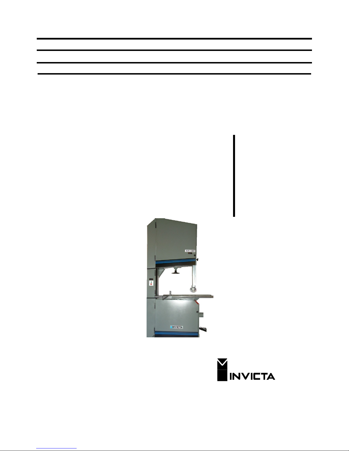
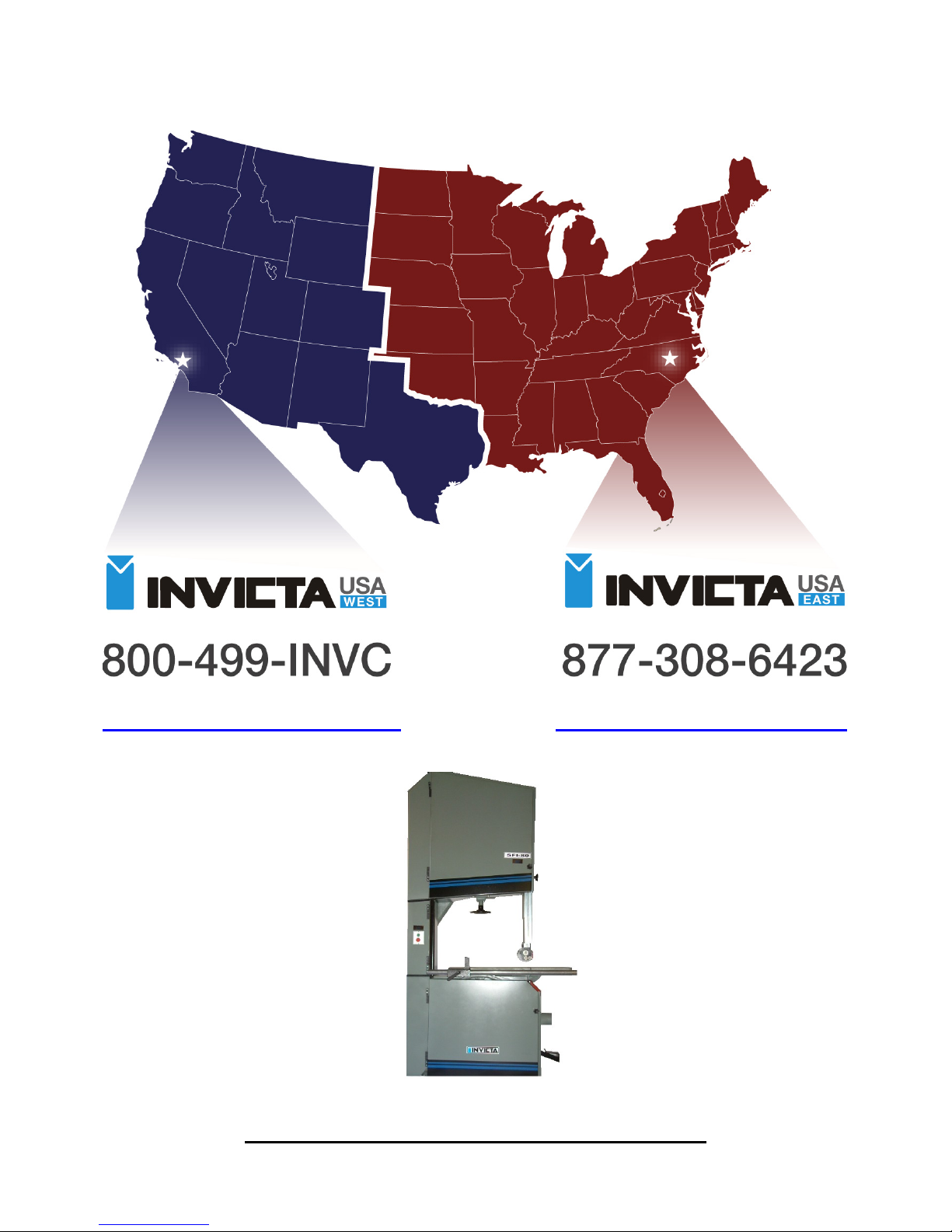
OPERATORS MANUAL
Band Saw
by
INVICTA
Model
SFI-80
INVICTA USA English Version
(877) 308-6423 - East
(800) 499-4682 - West
Page 2

1
Band Sa
w
Mod. SFI-80
General Instructions
Thank you for purchasing this quality machine from INVICTA.
As with all equipment, safety is to be the priority. The operator should understand the safety features as well as
apply good safety habits in transportation, adjustment, maintenance and operation of the machine. Practice and
teach others the safe operating procedures of this machine and help to prevent the possibility of accidents.
Safety Rules
1. For your own safety, read carefully the Instruction Manual before attempting to operate the machine.
2. If you are not thoroughly familiar and comfortable with the adjustment and operation of the machine, ask for
instruction from your supervisor or a fully qualified person. You may also contact Invicta USA.
3. Before the initial operation of the machine, remove all packaging, shipping grease and fully assemble the
machine. Pay special attention to the assembly of safety components.
4. Wear proper apparel while operating the machine. Never wear loose fitting clothing, gloves or ties. Always
remove rings or other jewelry before operating the machine. It is strongly suggested the operator wear
shoes with non-slip soles and also wear a protective hair net to prevent hair entanglement in moving parts.
5. Always wear personal safety equipment. Follow the safety regulations of your country and your company.
6. Have a certified person make all wiring connections to power source and properly ground the machine.
7. Always disconnect the machine from the power source and use lockout procedures before servicing,
changing cutting tools and during cleaning of the machine.
8. Before starting the machine, have the work area clean and free of debris. Cluttered areas are invitations for
accidents to occur.
9. Keep all safety guard(s) of the machine in place and in proper working condition. Never operate machinery
without safety equipment in place. Report any damage to your supervisor.
10. Keep children and visitors a safe distance from the working area.
11. Never leave the machine running while unattended. Turn off the power source during breaks. Before
walking away, allow the machine to come to a complete stop.
12. Do not operate the machine under the influence of drugs or alcohol. Consult your physician when taking
medications.
13. Do not force the machine beyond its limitations. It will produce a nicer and safer job at the rate it was
designed to operate.
Loading and Unloading
During loading and unloading, the machine should not be lifted by
components which could become damaged and affect it’s functioning.
The correct procedure is shown in figure 1.
NOTE: To remove the upper cover “A”, us e the ey e bolt “B ” Figur e 1. D o
not transport the machine through any point other than the eye bolts.
After this, reassemble and cover all the non painted surfaces with a
good quality paste wax.
A
B
Fig. 1
Page 3
2
Band Sa
w
Mod. SFI-80
Fastening the Machine to the Floor
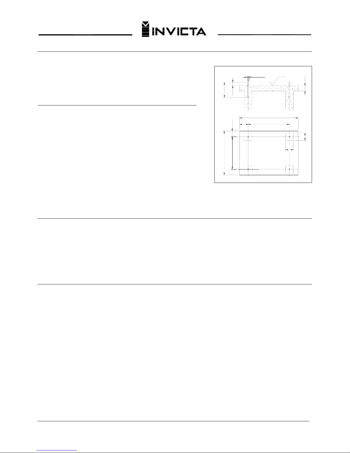
To prevent vibration, set the machine correctly on the floor. The spacing
of concrete anchors is shown in figure 2 sketch.
Electrical Connection
The machine name plate supplies the specifications of the motor and
voltage requirements. Check the name plate for the voltage
requirements and cycles (Hz) before connecting the electrical power.
After completing the connection of the power lines, switch the machine
on and off quickly to see if the rotation of the wheel is clockwise while
standing at the operator’s position. If not, reverse any two of three
phases of power line, without changing the internal wiring of the
machine.
NOTE: If the machine has manual star delta starter, turn it to the start
position (star) and as soon as the motor reaches its maximum speed,
change over to the run position. Never do any work with the switch at
the start position.
Lubrication
Your machine requires periodic lubrication as follows:
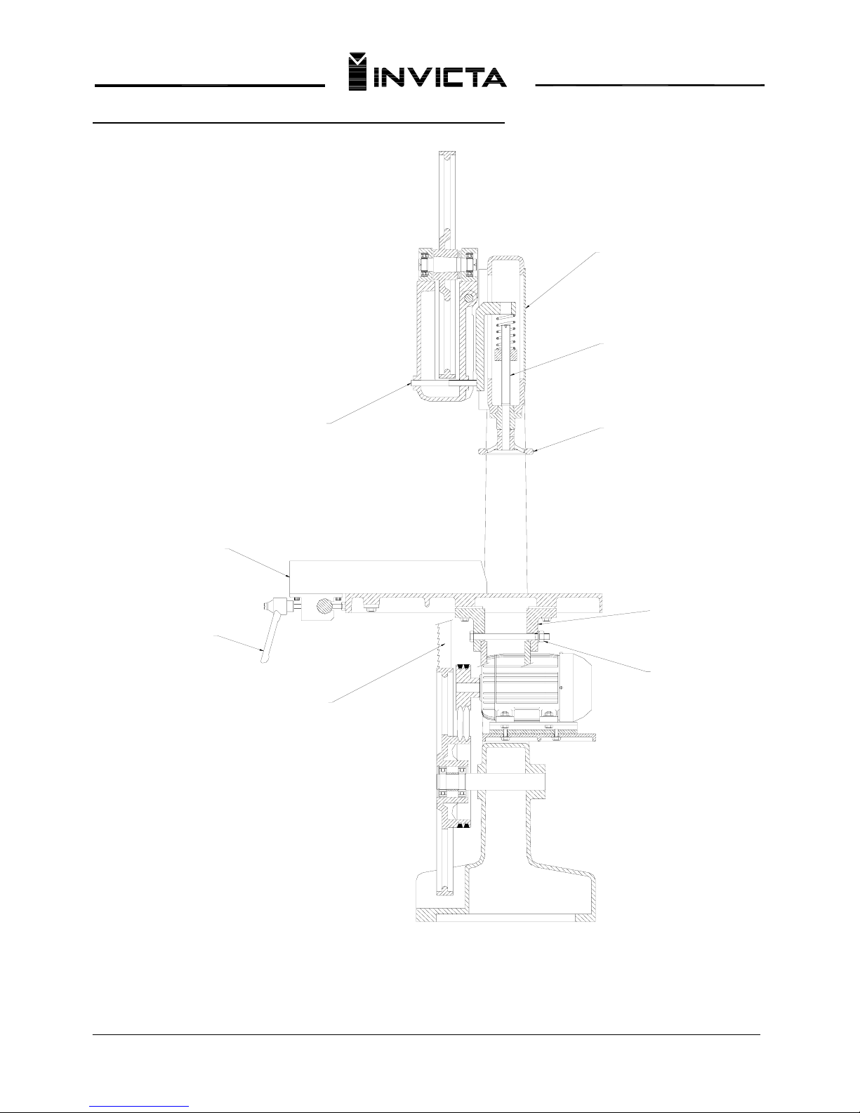
1. Remove the guard “G” (Page 05). Lubricate the screw “H” with standard grease.
2. The threaded adjustment tee “43” should be lubricated with the same standard grease used for the screw.
3. The top wheel supporting slide “J” (Page 05) should be lubricated with standard grease.
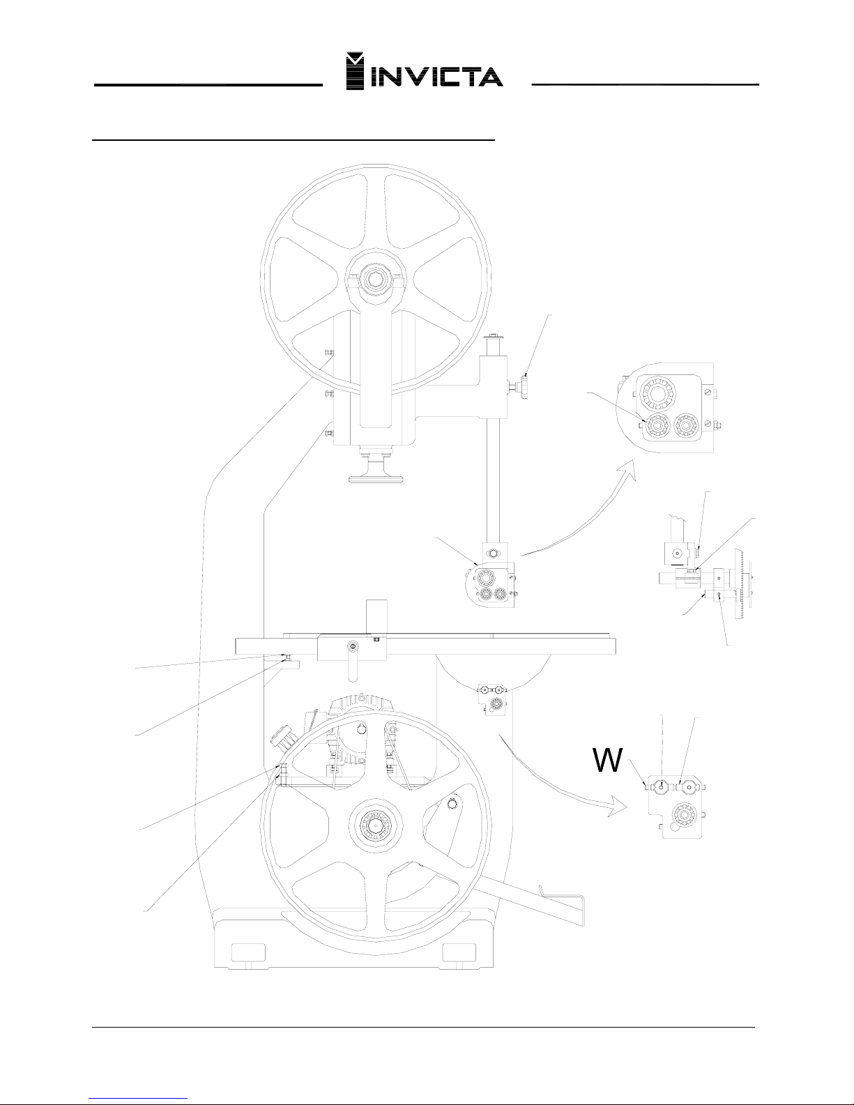
Adjusting the Guide
W.5/8"
150
45
130
1030
510
770
130
770
100
100
Level
70
Fig. 2
1. To adjust the cutting height, loosen knob “P” (Page 06), then move the guide up to the desired height and
tighten knob again.
2. The screw “S” and “T” (Page 06) are used to adjust the blade guide for blade width and fine tracking.
3. To adjust the top blade guide bearings “Q”, loosen the locking screw “V” (Page 06) with a 3mm Allen
wrench. Adjustment is made by turning the eccentric shafts which the bearings are mounted using a 6mm
Allen wrench. For the axial adjustment “Q”, pull the shafts forward till you met the blade and lock screw.
4. To adjust the lower blade guide, loosen screws “X” (Page 06) with a 3mm Allen wrench until the bearing
lightly touches the saw blade. Then retighten.
NOTE: The guide pins “Y” should center the saw blade. If it is necessary, center the pins to the desired position
and fasten the lock screws again.
Page 4
3
Band Sa
w
Mod. SFI-80
Adjusting the Belts
The belt tension adjustment is changed by bolt “N” and nut “O”, as shown in figure page 06. Do not over tighten or
premature belt wear will occur. Use just enough tension so that the belt does not slip under heavy cutting.
Adjusting the Table
Your machine is equipped with a fixed stop at 90º. To readjust this setting, loosen nut “L” and turn bolt “M” (Page
06) to the desired position. Relock nut “L” correctly.
Adjusting the Table Tilt
The work table will tilt up to 45º to the right. To adjust this feature, proceed as follows: loosen nut “K”, tilt the table
to the desired position and retighten (Page 05)
Adjusting the Rip Fence
Loosen the adjustable handle “E” and move the rip fence “D” (Page 05) in the desired direction to achieve the
proper cutting dimension. Lock in position using handle “E”.
Installing the Saw Blade
1. Turn the blade tension adjusting knob “I” (Page 05), and lower the top blade wheel.
NOTE: Safety guard “R” must be removed to install the saw blade (Page 06). Replace the safety guard when blade
is in place.
2. Tensioning the saw blade “F” (Page 05) is achieved by turning knob “I” to the correct setting.
NOTE: Correct blade tensioning is necessary for the blade to remain on the wheels when cutting. Release the saw
blade tension if the machine will not be used for an extended period of time. This will increase the blade life.
3. Perfect alignment of the saw blade on the rubber covered wheel is reached by turning screw “C” (Page 05) with
the 8mm Allen wrench. Blades should normally track center of the wheel.
Replacement Parts
Every INVICTA machine has a serial number which enables the manufacturer to identify the exact type and date of
its manufacture. At the end of this manual you will find a list of parts which compose your machine with their names
and numbers. Use only genuine INVICTA parts and on your order alwa ys mention the serial number, part number
and quantity desired.
Page 5

4
Band Sa
w
Mod. SFI-80
Technical Specifications
Diameter of Wheels…………………………………………………………………………………… 31 ½”
Width of Wheels………………………………………………………………………………………
2”
Speed of Wheels………………………………………………………………………………………… 600 RPM
Maximum Cutting Height……………………………………………………………………………… 18 ½”
Maximum Cutting Width……………………………………………………………………………… 30 45/64”
Minimum Saw Blade Length………………………………………………………………………… 218 37/64”
Maximum Saw Blade Length………………………………………………………………………… 226 27/32”
Maximum Saw Blade Width…………………………………………………………………………… 1 37/64”
Table Size………………………………………………………………………………………………… 30 45/64”x39 3/8”
Table Tilting to Right…………………………………………………………………………………… 45º
Working Height………………………………………………………………………………………… 36 7/32”
Three Phase Motor Power…………………………………………………………………………… 7.5 HP
Page 6
5
Band Sa
w
Mod. SFI-80
Side View Showing Adjustment and Lubrication Points
E
D
F
J
C
G
I
H
K
Page 7
6
Band Sa
w
Mod. SFI-80
Front View Showing Table-Guides-Motor Adjustments
R
L
M
N
O
Y
X
P
U
V
T
S
Q
Page 8
7
Band Sa
w
Mod. SFI-80
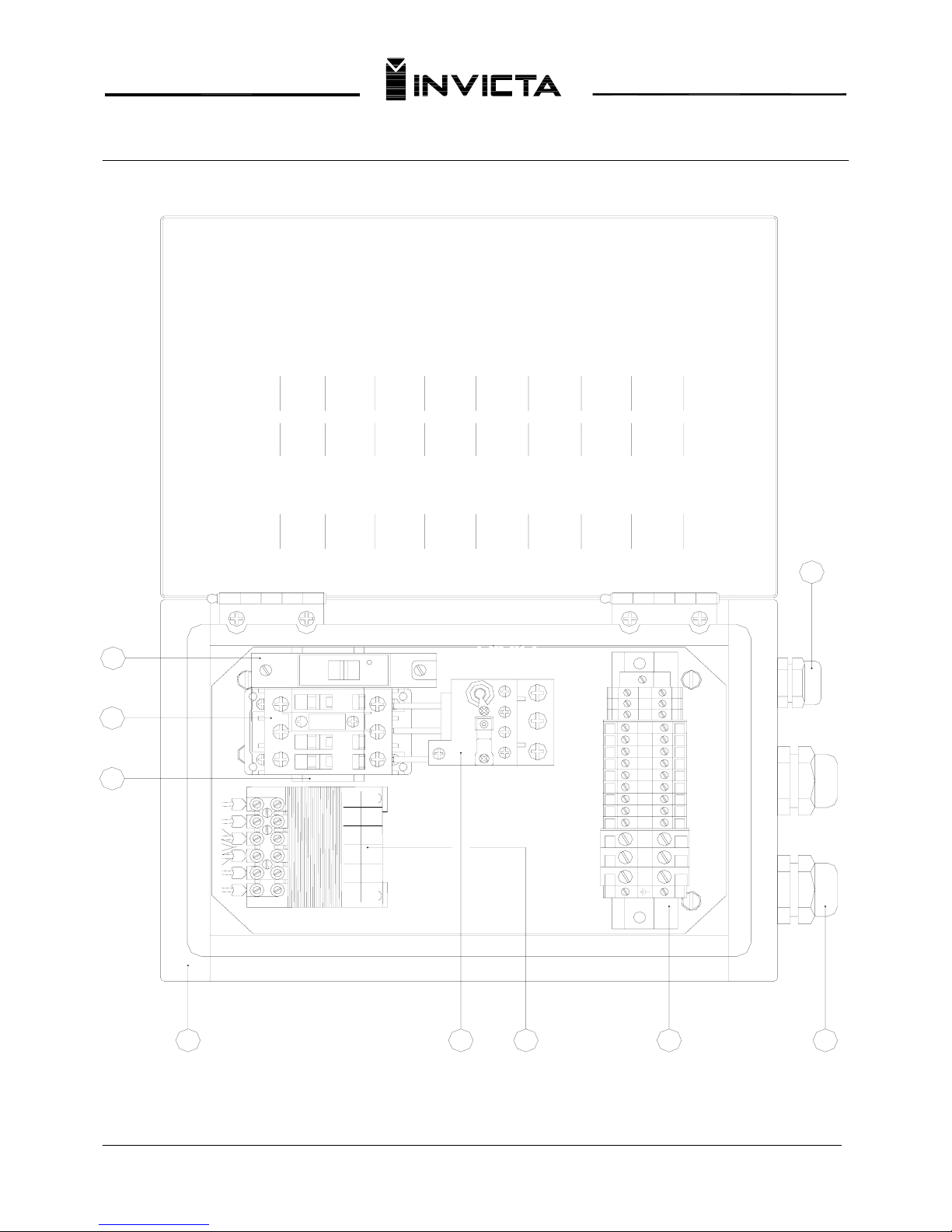
ELECTRICAL BOX DIAGRAM
230V
3
3
T
1
24V
6
5
6
4
Ø V
5
460V
4
8
6
5
7
R
S
4
2
1
208V
2
Ø V
1
A1
1 L1 3 L2
1-
A1
2 T1
2-
4 T2
3
2
5 L3
A2
3NO
3-
4NO
6 T3
4-
A2
PART. N°
11-28-0023
11-34-0012
11-07-0069
11-25-0003
ITEM
1
2
3
4
QTY.
1
1
1
1
Disjuntor C6A5SX1-1
Electrical box
Contactor CWM25
NAME
Track
9
98 NO96 NC
A2
21 345678
97 NO 95 NC
1110 12
11-31-0007
11-02-0067
11-03-0015
11-03-0009
11-20-0009
8
6
5
7
9
9
2
1
2
1
1
Overload relay RW27D
Single phase transformer
Press cable PG21
Post Block
Press cable PG13.5
Page 9
8
Band Sa
w
Mod. SFI-80
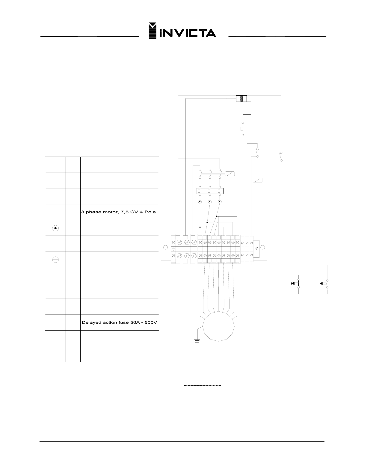
ELETRIC DIAGRAM 230V
M
c1
e2
CONNECTION TO BE MADE BY CUSTOMER
Contact CWM25
1
230V - 15 a 23A
Bi-metal relay RW27D
1
a1 e1
MOTOR
3
QTY.
TR
d1
e1
a2
a1
M
b0
b1
CODO
-Entry 230/460v-Quit 24v
Transformer
1
R
Circuit breaker 6A
3
1
Switch Reverse
1
Master switch
1
Post block
21
9
~
21345 768
TS
21354876
1110912
Terminal
1
1
Off button - red
1
On button - green
1
NAME
21 3
e2
A1
c1
A2
c1
b0
b1
13
14
d1
e2
3
1
6
24V
5
Page 10
9
Band Sa
w
Mod. SFI-80
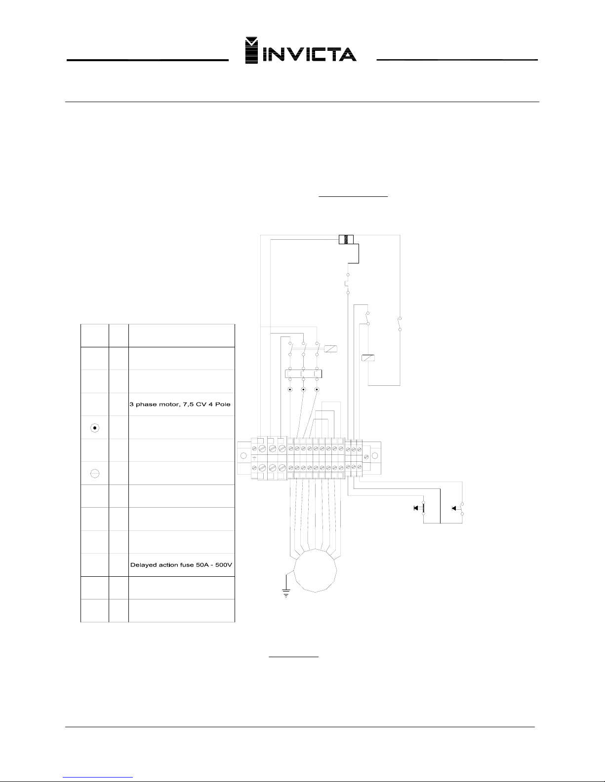
ELETRIC DIAGRAM 460V
M
c1
e2
CONNECTION TO BE MADE BY CUSTOMER
Contact CWM25
1
460V - 8 a 12A
Bi-metal relay RW27D
1
a1 e1
MOTOR
3
QTY.
TR
d1
e1
a2
a1
M
b0
b1
CODO
-Entry 230/460v-Quit 24v
Transformer
1
R
Circuit breaker 6A
3
1
Switch Reverse
1
Master switch
1
Post block21
9
~
21345 768
TS
21354876
1110912
Terminal
1
1
Off button - red
1
On button - green
1
NAME
213
e2
A1
c1
A2
c1
b0 b1
13
14
d1
e2
4
1
6
24V
5
3 N-60 HZ - 460V
M
c1
e2
CONNECTION TO BE MADE BY CUSTOMER
Contact CWM25
1
460V - 8 a 12A
Bi-metal relay RW27D
1
a1 e1
MOTOR
3
QTY.
TR
d1
e1
a2
a1
M
b0
b1
CODO
-Entry 230/460v-Quit 24v
Transformer
1
R
Circuit breaker 6A
3
1
Switch Reverse
1
Master switch
1
Post block
21
9
~
21345 768
TS
21354876
1110912
Terminal
1
1
Off button - red
1
On button - green
1
NAME
213
e2
A1
c1
A2
c1
b0 b1
13
14
d1
e2
4
1
6
24V
5
3 N-60 HZ - 460V
Page 11
10
Band Sa
w
Mod. SFI-80
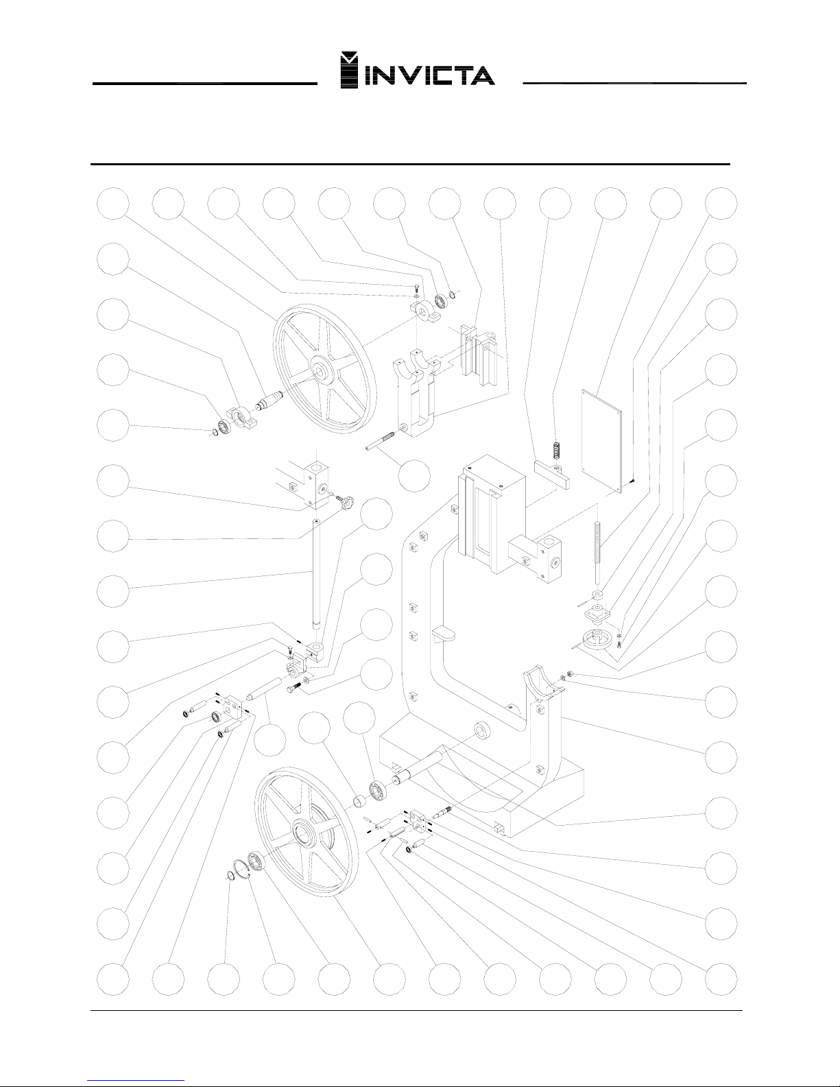
Replacement Parts (1 – 58)
08
15 16
14
13
12
11
09
10
07
06
05
04
03
02
01
17 18 19 20 21 22 23 24 25 26
27
28
29
30
31
32
33
34
35
36
37
38
39
40414243
4445
46
47
484950
51
52
53
54
55
56
57
58
Page 12
11
Band Sa
w
Mod. SFI-80
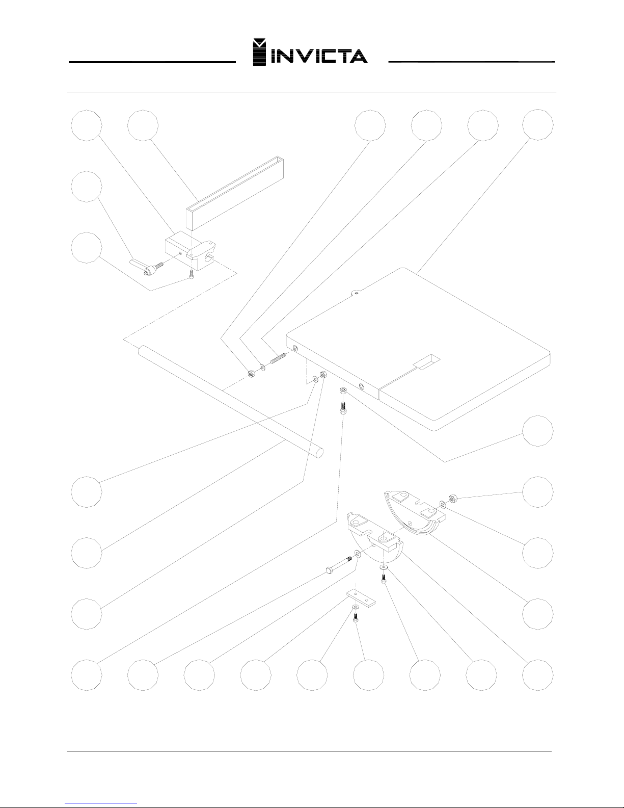
Replacement Parts (59 – 82)
6765
64
66
62
63
61
59
60
82
716968 70
74
7372
76
77
75
8081
78
79
Page 13
12
Band Sa
w
Mod. SFI-80
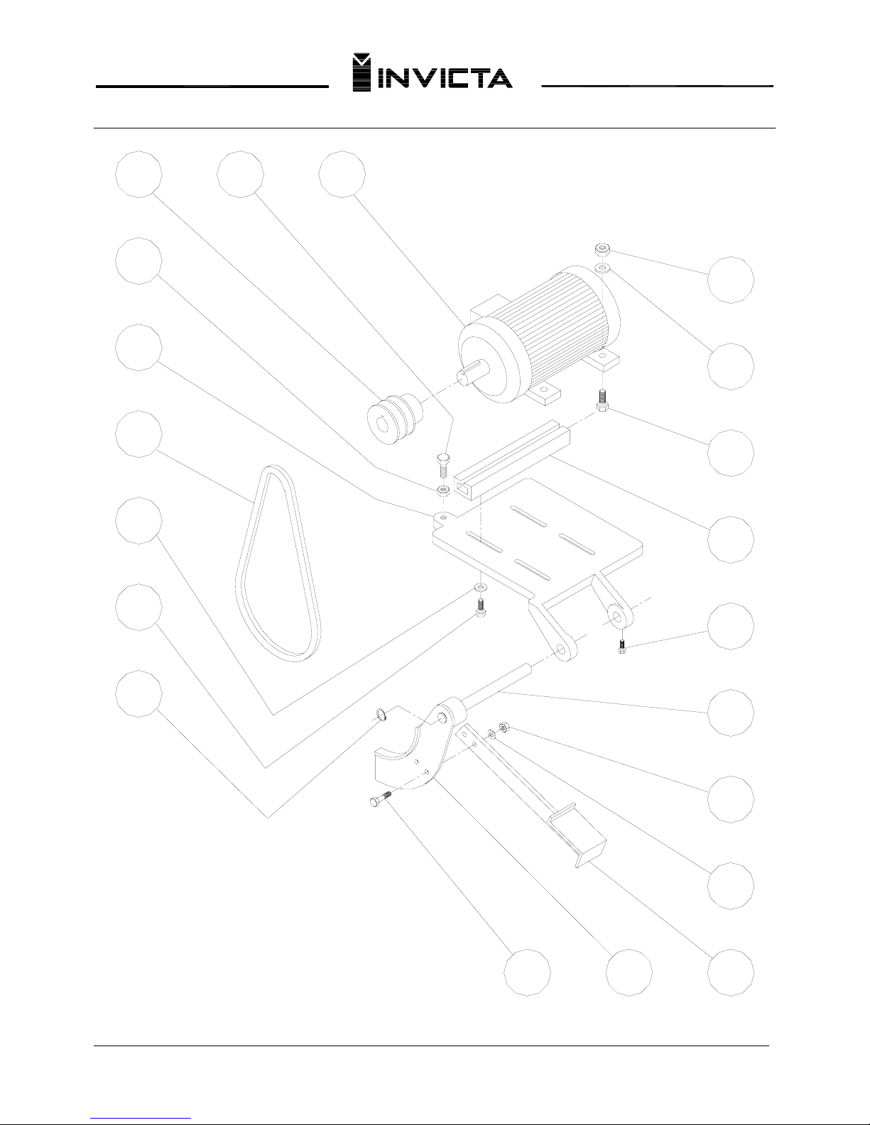
Replacement Parts (83 – 102)
101
89
88
86
87
85
83
84
102
90
93
9291
96
95
94
99
98
97
100
Page 14
13
Band Sa
w
Mod. SFI-80
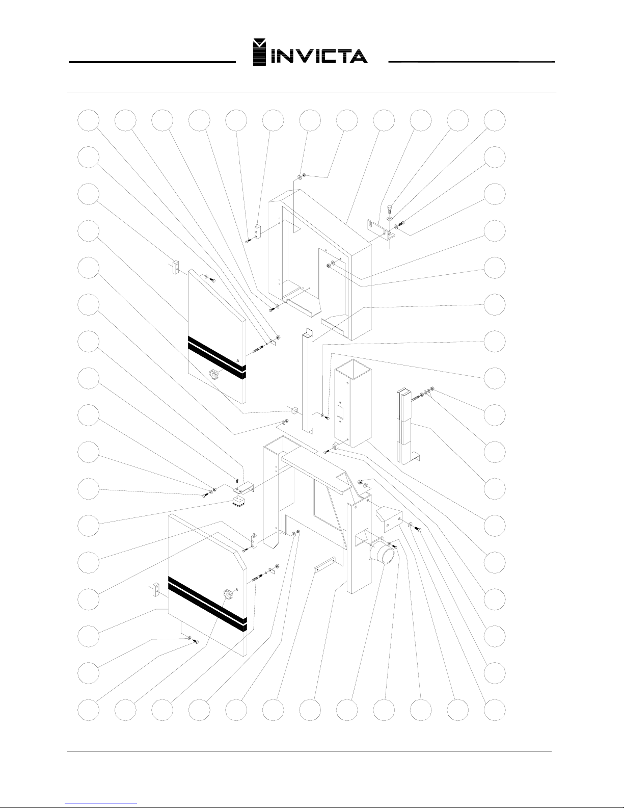
Replacement Parts (103 – 156)
120
118
119
117
121 122
115
116
114
112
113
106
109
111
110
108
107
156
105
104
103 155 154
125123 124 126 127
132
130
131
128 129
136
137
135
133
134
151153 152 150 149
143
142
141
139
138
140
145
144
146148 147
Page 15
14
Band Saw
Mod. SFI-80
FIG. Nº CODE QTY. NAME FIG. Nº CODE QTY. NAME
01.......... 83SF-K051-0 01…... Upper wheel 35……... 06-04-0018-0 04….. Hex head screw UNC 3/8”x1
02.......... 83SF-KK13-0 01…... Upper wheel axle 36……... 06-13-0004-0 04….. Flat washer Ø3/8”
03.......... 83SF-KK15-0 01…... Upper bearing block (outer) 37……... 83SF-KK21-0 01….. Adjustment screw flange
04.......... 03-00-0033-0 01…... Bearing Nr. 6206-2RS 38……... 8NAN-K111-0 01….. Collar
05……... 06-18-0012-0 01…... E-10 external retaining ring 39……... 83SF-KK32-0 01….. Blade tension adjustment screw
06……... 83SF-KK31-0 01…... Spacer 40……... 06-05-0010-0 04….. Round cap screw ¼” x 3/8”
07……... 27-01-0005-0 01…... Knob 41……... 83SF-KK23-0 01….. Top adjustment cover
08……... 83SF-KK24-0 01…... Upper guide shaft 42……... 07-00-0014-0 01….. Compression Spring
09……... 06-02-0102-0 01…... UNC 3/8” set screw 43……... 83SF-KK30-0 01….. Screw spport
10……... 06-04-0018-0 01…... Hex head screw UNC 3/8” x 1 ¼” 44……... 83SF-KKK4-0 01….. Support U
11……... 06-13-0004-0 01…... Flat washer Ø3/8” 45……... 83SF-KKK3-0 01….. Adjustment block
12……... 03-00-0030-0 01…... Bearing NR 6204-ZZ 46……... 06-18-0012-0 01….. External retaining ring E-10
13……... 82SF-K150-0 01…... Outer bearing guide support 47……... 03-00-0033-0 01….. Bearing Nr. 6206-2RS
14……... 03-00-0023-0 02…... Bearing Nr.6201-ZZ 48……... 83SF-KK14-0 01….. Upper bearing block (inner)
15……... 82SF-K153-0 02…... Upper small bearing pin 49……… 06-04-0018-0 02….. Hex head screw UNC 3/8”x1 3/4”
16……... 06-02-0013-0 03…... UNC 3/8” x 5/8” set screw 50……... 8NAR-KK98-0 02….. Washer
17……... 06-18-0014-0 01…... E-40 external retaining ring 51……... 83SF-2K87-0 01….. Mounting stud
18……... 06-18-0026-0 01…... 1-80 internal retaining ring 52…….... 82SF-KK29-0 01….. Blade guide base
19……... 03-00-0077-0 01…... Bearing Nr.6208-2RS 53……... 82SF-KK28-0 01….. Blade guide adapter block
20……... 83SF-K050--0 01…... Lower wheel 54……... 06-13-0004-0 01….. Flat washer Ø3/8”
21……... 06-02-0013-0 02…... UNC 3/8” x 5/8” set screw 55……... 06-04-0017-0 01….. Hex head screw UNC 3/8”x1”
22……... 82SF-K157-0 02…... Lower alignment pin 56……... 03-00-0077-0 01….. Bearing Nr. 6208-2RS
23……... 82SF-K156-0 02…... Pin 57……... 83SF-KK29-0 01….. Spacer
24……... 03-00-0023-0 01…... Bearing Nr. 6201-ZZ 58……... 82SF-KK59-0 01….. Guide slide shaft
25……... 82SF-K155-0 01…... Lower bearing pin 59……... 82SF-K121-0 01….. Rip fence base
26……... 82SF-K153-0 04…... UNC 3/8” x 5/8” set screw 60……... 27-00-0020-0 01….. Adjustable handle
27……... 82SF-K150-0 01…... Guide block support 61……... 06-03-0061-0 02….. Allen screw with head M8x30
28……... 82SF-K152-0 01…... Guide block support stud 62……... 06-13-0005-0 02….. Washer Ø1/2”
29……... 83SF-KK22-0 01…... Lower wheel axle 63……... 83SF-2K88-0 01….. Rip fence rod
30……... 83SF-KKK1-0 01…... Saw base 64……... 06-09-0022-0 02….. Hex nut M12
31……... 06-13-0006-0 01…... Flat washer Ø5/8” 65……... 06-04-0145-0 01….. Hex head screw UNC ½”x1 ½”
32……... 06-09-0007-0 01…... UNC 5/8” hex nut 66……... 06-04-0092-0 01….. Hex head screw UNC 5/8”x7 ½”
33……... 26-01-0008-0 01…... Ø5x40 roll pin 67…….. 06-13-0006-0 01….. Flat washer Ø5/8”
34……... 8NVO-KKK7-0 01….. Hand wheel 68…….. 82SF-KK44-0 01….. Table protector
Page 16
15
Band Saw
Mod. SFI-80
CODE QTY. NAME FIG. Nº CODE QTY. NAME
69…….. 06-13-0006-0 02….. Flat washer Ø1/2” 105…… 16-20-0008-0 04….. Upper door hinge block
70…….. 06-04-0143-0 02….. Hex head screw Ø1/2”x1” 106…… 83SF-2K77-0 01….. Upper protection door
71…….. 06-04-0018-0 02….. Hex head screw UNC 3/8”x1 3/4” 107…… 16-20-0008-0 02….. Hinge
72…….. 06-13-0005-0 02….. Flat washer Ø1/2” 108…… 06-13-0002-0 02….. Flat washer Ø1/4”
73…….. 82SF-2158-0 01….. Table tilt Trunion (outer) 109…… 83SF-2K82-0 01….. Brush support
74…….. 82SF-2158-0 01….. Table tilt Trunion (inner) 110…… 06-08-0002- 0 02….. Flat head screw ¾”x8mm
75…….. 06-13-0006-0 01….. Flat washer Ø5/8” 111…… 06-09-0003-0 02….. Hex nut ¼”
76…….. 06-09-0007-0 01….. Hex nut UNC 5/8” 112…… 06-13-0002-0 02….. Flat washer ¼”
77…….. 06-09-0029-0 01….. Hex nut UNC ½” 113…… 06-04-0068-0 02….. Hex head screw UNC1/4”x5/8”
78…….. 83SF-KKK2-0 01….. Cast Table 114…… 16-28-0004-0 01….. Wheel Brush
79…….. 8NVR-K102-0 02….. Stud 115…… 16-20-0009-0 02….. Lower door hinge base
80…….. 06-13-0005-0 02….. Washer 116…… 06-04-0096-0 04….. Hex head screw M6x1x25
81…….. 06-09-0022-0 02….. Hex nut M12 117…… 83SF-2K80-0 01….. Lower protector door
82…….. 83SF-2K96-0 01….. Rip Fence 118…… 06-13-0038-0 04….. Washer Ø6mm
83…….. 8NPM-2K87-0 01….. Motor pulley-60HZ 119…… 06-04-0096-0 04….. Hex head screw M6x1x25
84…….. 06-09-0029-0 01….. Hex nut UNC ½” 120…… 27-01-0045-0 02….. Door locking knob
85…….. 83SF-2K98-0 01….. Motor base plate 121…… 82SF-K124-0 02….. Stud
86…….. 15-00-0068-0 02….. Vee Belt 3V 450 122…… 06-13-0038-0 02….. Flat washer Ø6mm
87…….. 06-13-0004-0 04….. Flat washer Ø3/8” 123…… 06-09-0019-0 02….. Hex nut M6x1
88…….. 06-04-0016-0 04….. Hex head screw UNC 3/8”x1 1/2” 124…… 82SF-K117-0 01….. Chip bonnet support bar
89…….. 06-18-0008-0 01….. E-20 external retaining ring 125…… 83SF-2K68-0 01….. Lower protection cover
90…….. 06-04-0040-0 02….. Hex head screw UNC 5/8”x1 1/2” 126…… 82SB-KK24-0 01….. Chip bonnet
91…….. 83SF-K112--0 01….. Brake Arm 127…… 06-04-0005-0 02….. Hex head screw UNC 5/16”x5/8”
92…….. 83SF-K116-0 01….. Brake pedal bar 128…… 06-13-0003-0 02….. Flat washer 5/16”
93…….. 06-13-0006-0 02….. Flat Washer Ø 5/8” 129…… 83SF-2K86-0 01….. Lower blade protection
94…….. 63-60-0069-0 02….. Hex Nut UNC 5/8” 130…… 06-13-0001-0 04….. Washer Ø3/6”
95…….. 82SF-K172-0 01….. Motor Base and brake shaft 131…… 06-05-0004-0 02….. Round head screw UNC3/16”x1/2”
96…….. 06-04-0017-0 02….. Hex head screw UNC 3/8”x1” 132…… 06-09-0002-0 02….. Hex Nut UNC 3/16”
97…….. 8NTR-KK26-0 02….. Motor adapter bar 133…… 06-04-0096-0 02….. Hex head screw M6x1x25
98…….. 06-04-0016-0 04….. Hex head screw UNC 3/8”x1 ½” 134…… 16-20-0009-0 02….. Hinge
99…….. 06-13-0004-0 04….. Flat washer Ø 3/8” 135…… 83SF-2K63-0 01….. Upper blade protection
100…… 06-09-0005-0 04….. Hex nut UNC 3/8” 136…… 83SF-2K99-0 01….. Telescoping blade protection
101…… 29-35-0030-0 01….. Three phase motor –7.5Hp 230v 137…… 8NAR-KK98-0 02….. Washer Ø10mm
102…… 06-04-0152-0 01….. Hex head cap screw 138……. 06-09-0003-0 02….. Hex nut UNC ¼”
103…… 82SF-K125-0 02….. Lock finger 139……. 06-03-0096-0 02….. Hex head screw M6x1x25
104…… 06-18-0036-0 02….. Snap ring RS-5 140……. 06-13-0038-0 02….. Flat washer Ø6mm
Page 17
16
Band Sa
w
Mod. SFI-80
FIG. Nº CODE QTY. NAME
141…… 83SF-2K78-0 01….. Cover
142…… 06-09-0005-0 02….. Hex nut UNC 3/8”
143…… 8NAR-KK98-0 02….. Washer
144…… 8NAR-KK98-0 02….. Flat washer
145…… 06-04-0016-0 02….. Hex head screw UNC 3/8”x3/4”
146…… 8NAR-KK98-0 02….. Flat washer
147…… 06-04-0016-0 02….. Hex head screw UNC 3/8”x3/4”
148…… 83SF-2K81-0 01….. Upper protection support bracket
149…… 83SF-2K54-0 01….. Upper protection cover
150…… 06-09-0019-0 02….. Hex nut M6x1
151…… 06-13-0038-0 02….. Washer Ø6mm
152…… 16-20-0009-0 02….. Upper door hinge base
153…… 06-04-0096-0 04….. Hex head screw M6x1x25
154…… 06-13-0038-0 02….. Washer Ø6mm
155…… 06-04-0096-0 02….. Hex head screw M6x1x25
156…… 06-09-0020-0 02….. Hex Nut M8x1,25
Page 18
 Loading...