

Page 1
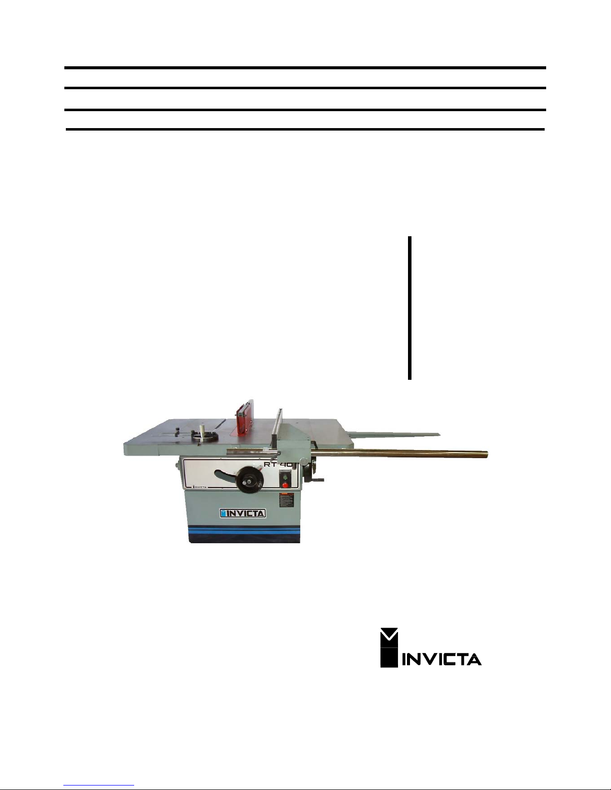
OPERATORS MANUAL
HEAVY DUTY TABLESAW
by
INVICTA
Model
RT-40
INVICTA USA English Version
(877) 308-6423 - East
(800) 499-4682 - West
Page 2

1
Table Saw
Mod. RT-40
General Instructions
Thank you for purchasing this quality machine from INVICTA.
As with all equipment, safety is to be the priority. The operator should understand the safety features as well as
apply good safety habits in transportation, adjustment, maintenance and operation of the machine. Practice and
teach others the safe operating procedures of this machine and help to prevent the possibility of accidents.
Safety Rules
1. For your own safety, read carefully the Instruction Manual before attempting to operate the machine.
2. If you are not thoroughly familiar and comfortable with the adjustment and operation of the machine, ask for
instruction from your supervisor or a fully qualified person. You may also contact Invicta USA.
3. Before the initial operation of the machine, remove all packaging, shipping grease and fully assemble the
machine. Pay special attention to the assembly of safety components.
4. Wear proper apparel while operating the machine. Never wear loose fitting clothing, gloves or ties. Always
remove rings or other jewelry before operating the machine. It is strongly suggested the operator wear
shoes with non-slip soles and also wear a protective hair net to prevent hair entanglement in moving parts.
5. Always wear personal safety equipment. Follow the safety regulations of your country and your company.
6. Have a certified person make all wiring connections to power source and properly ground the machine.
7. Always disconnect the machine from the power source and use lockout procedures before servicing,
changing cutting tools and during cleaning of the machine.
8. Before starting the machine, have the work area clean and free of debris. Cluttered areas are invitations for
accidents to occur.
9. Keep the safety guard(s) of the machine in place and in proper working condition. Never operate
machinery without safety equipment in place. Report any damage to your supervisor.
10. Keep children and visitors a safe distance from the working area.
11. Never leave the machine running while unattended. Turn off the power source during breaks. The machine
should come to a complete stop before walking away.
12. Do not operate the machine under the influence of drugs or alcohol. Consult your physician when taking
medications.
13. Do not force the machine beyond its limitations. It will produce a nicer and safer job at the rate it was
designed to operate.
Additional Safety Rules for the Operation of Table Saws
1) Avoid Kickbacks. “Kickback” can occur when the workpiece is forced back by the saw blade during improper
operation. When “Kickback” occurs injury can result. Some causes of Kickback are:
A- Dull blades or an improperly adjusted fence in relation to the blade.
B- Knots, Nails or Imperfections in the workpiece.
C- Heavier cutting than the machine was designed for.
D- Failure to use a pusher block when cutting thin or narrow workpieces.
2) Never start the work-piece into the blade before allowing it to reach full operation speed.
3) Use the correct tooth style and rake for the material you plan to cut.
4) Keep the Blade sharp and free of rust and pitch
5) Use good safety habits when using dado blades.
6) Support and control the workpiece properly all times during the operation.
7) Never reverse the direction of the workpiece after beginning operation. Kickback can occur.
8) Definitions of ripping, crosscutting and dadoing of the workpiece:
A- Ripping operations: Cutting the material in the same direct as the flow of the grain.
B- Crosscutting operations: Cutting the material across the grain. This may produce heavy splintering.
C- Dado operations: Cutting a flat-wide bottom grove in the material.
Page 3
2
Table Saw
Mod. RT-40
Loading and Unloading
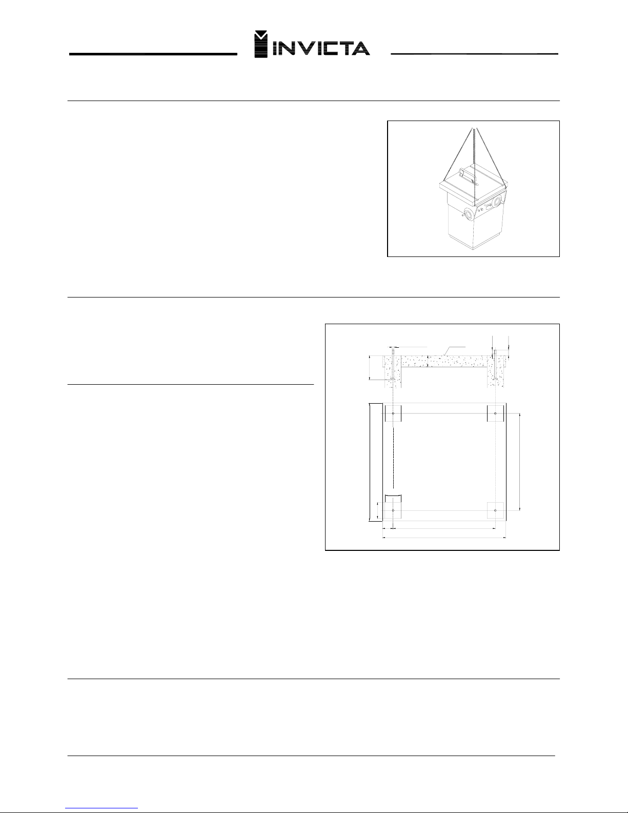
Fig.01
Never load or unload the machine by any component that could be
damaged. Transporting the machine by the directions in Fig.01 is the
recommended procedure.
After placement has been completed, remove all the protective grease
or varnish from the machined surfaces using kerosene or a similar
solvent.
Installing the machine
On a solid surface, level the machine (Fig.02) then add all
attachments such as the blade guard and fences.
Connecting Electricity
Each machine is provided with a reference plate that
indicates the requirements for electrical service needed
for the machine to operate property. Before you call a
certified electrician to make the wiring connections, be
sure that the voltage and cycle (phase) stated on this
reference plate are the same as provided in your building.
(Electrician) Remove the electrical box cover and connect
the electrical supply wires to the proper terminals. Rapidly
turn on and off the machine and then visibly check the
rotation direction of the saw blade. It should rotate so as
the top of the exposed blade travels toward the operator’s
position while sawing. See page 7
For changing blade direction for three-phase machines:
invert two wires of the power source without changing the internal connections of the machine. Should further
information be needed please contact Invicta USA.
IMPORTANT:
If your machine is equipped with a star-triangle switch (Y∆), first turn it to the start position and when the motor
reaches its maximum speed turn it immediately to the triangle position. Never operate the machine with the swich
in the start position or damage may occur.
Lubrication
730
600
±2
100
760
630
±2
65
100
LEVEL
M12 x 1,75
150
70
35
25
Fig.02
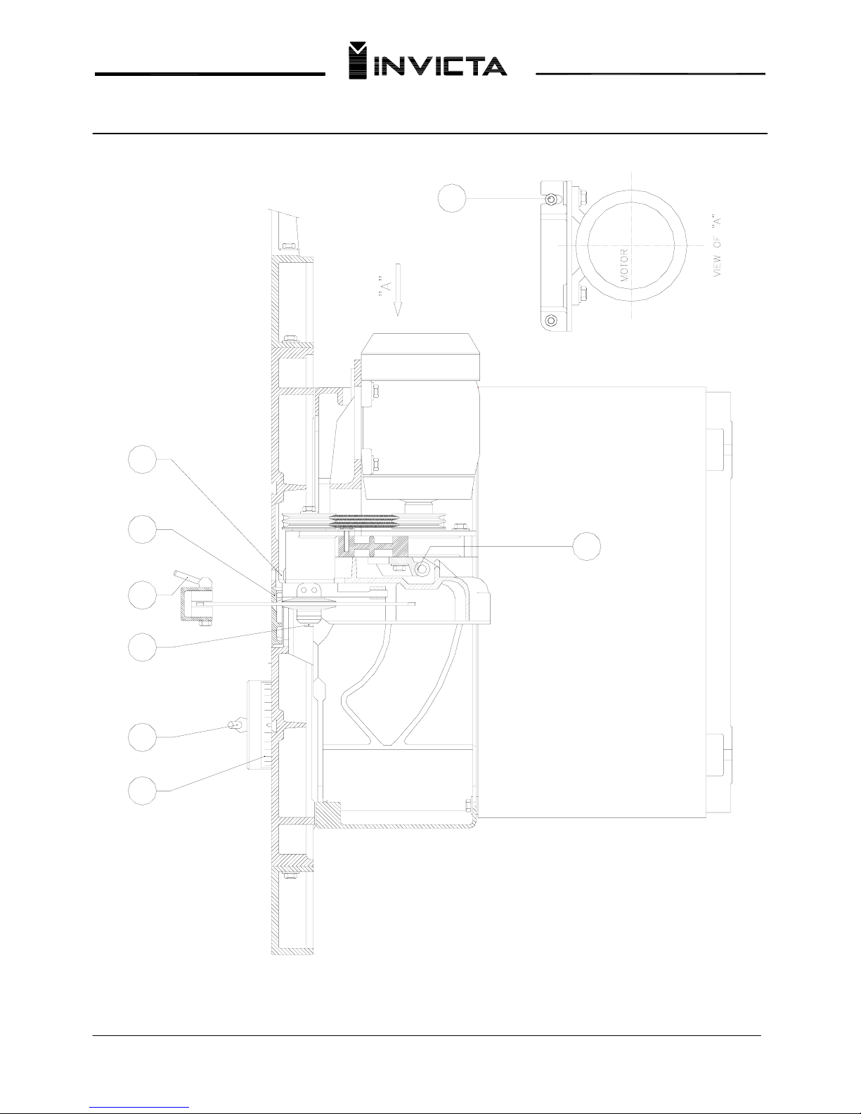
Your machine requires periodic lubrication as follows: Points “A” (pgs 07 and 08) should be cleaned with kerosene
and lubricated with common grease as required. The saw shaft bearings do not required lubrication as they are
sealed for life.
Page 4

3
Table Saw
Mod. RT-40
Controls
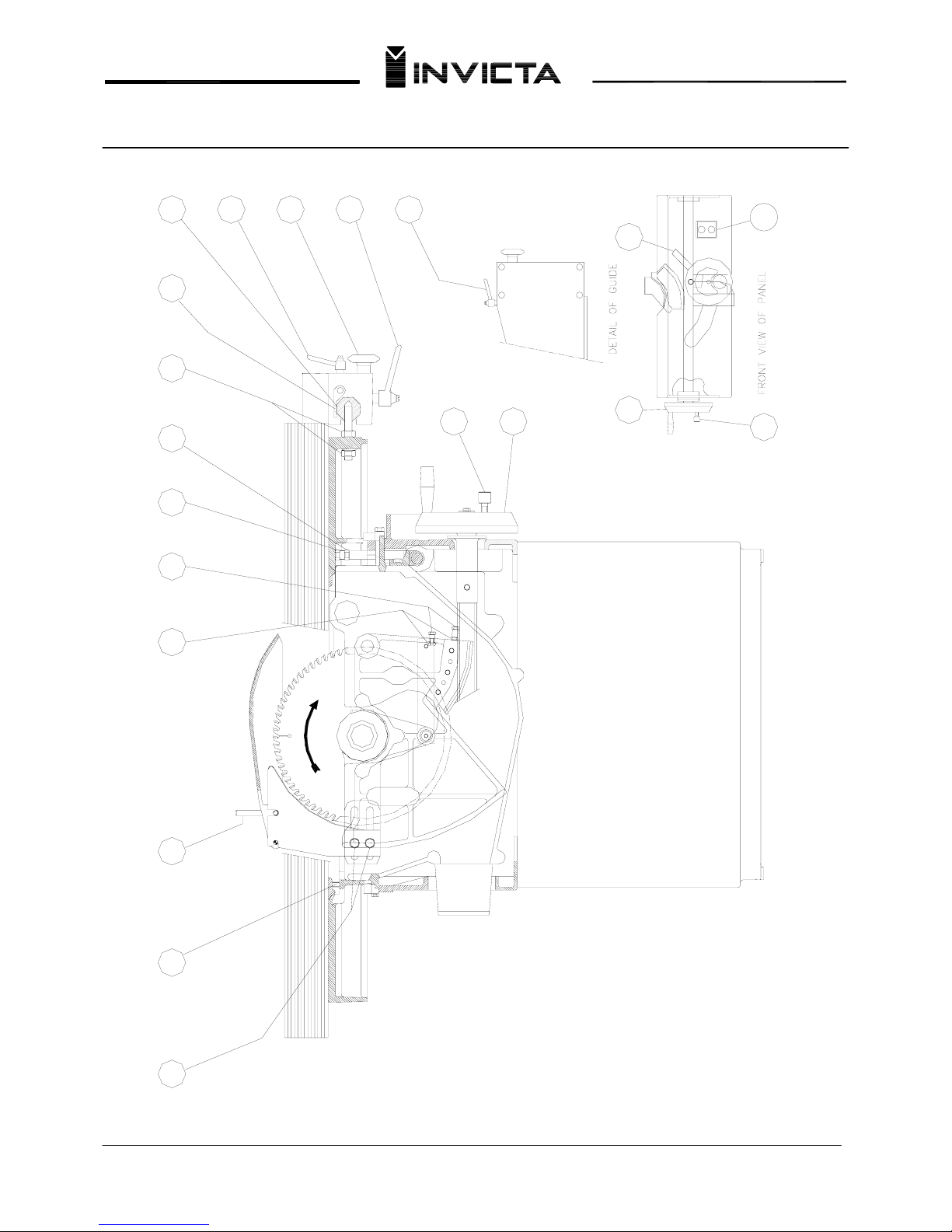
1. ELECTRIC SWITCH (pag. 07)
2. SAW TILT ADJUSTMENT HANDWHEEL (pag. 07)
This handwheel is used to adjust the tilt angle of the saw from 0º to 45º. To adjust this feature, loosen lock knob nº
4 then turn the handwheel nº 2 until the desired angle is obtained, relock. The angle is read on scale nº 5
3. SAW BLADE HEIGHT ADJUSTING HANDWHEEL (pag. 07)
This handwheel is used to adjust the amount of blade that protrudes through the top of the material. Before moving
the handwheel, loosen lock knob nº 6, then relock after the adjustment is completed.
Rip Fence Alignment
The relationship between the rip fence and the blade assembly has been aligned from the factory. Should the fence
require adjustment due to shipment, please follow the procedure below.
First loosen or tighten nuts nº 11 as needed until the desired parallel relationship is obtained between the saw
blade and the rip fence. Never adjust the rip fence so that the distance between the blade and fence on the output
end is less than on the input end. This slightly greater distance at the output side of the blade will decrease the
possibility of pinching or binding of the material.
Rip Fence Width Adjustment
Proceed as follows: First loosen lock lever nº 7 and turn knob nº 8 until the desired adjustment is obtained. Relock
by lever nº 7. The width of the cut is read on scale nº 9. To obtain the longitudinal adjustment of the guide it is
necessary to loosen the two knobs nº 10, retightening after adjustment.
Scale Pointer Adjustment (page 07)
The scale pointer may need occasional adjustment due to variations in saw blade kerfs. When adjustment is
necessary, proceed as follows: First, disconnect power supply then slide the rip fence gently against the saw blade.
Loosen knob nº 13 and adjust the pointer to zero on scale nº 9 to zero. Complete the adjustment by locking nº 13.
Adjustment of the tilt limit stops (page 07)
These stops are designed to give the blade an exact locator for 0º and 45º. These stops have been adjusted at the
factory. If later adjustment is necessary: place a precision square against the blade and adjust to 0º, loosen nut nº
14, and adjust acrew nº 15 until the blade stops at the correct position. Tighten nut nº 14. Follow the same
procedure for the 45º adjustment.
Vertical Saw Blade Adjustment (page 07)
Stops nº 16 limits the maximum and minimum height travel of the blade. These stops have been adjusted at the
factory. If future adjustment is necessary, loosen nuts nº 17 and adjust screw nº16 to increase or decrease the
blade travel. Once positioned, tighten nº 14 nuts. Do Not use a blade that is larger than specified.
Page 5

4
Table Saw
Mod. RT-40
Saw Guard Adjustment (page 07)
Saw guard/blade slitter adjustment is by handle nº 18. The saw guide/blade slitter support is adjusted by nuts nº19,
and should be readjusted according to the saw blade diameter each time the blade is changed.
Belt Tension Adjustment (page 08)
To adjust belt tension or change belts, loosen screw nº 20 and adjust as necessary. Tighten screws.
Procedure for Changing the Saw Blade (page 08)
Remove the saw guard by loosening the lock handle nº 18. Remove the table blade insert (item nº 21) and depress
the blade locking pin (item nº22). Loosen nut nº 23 with the special wrench supplied with the machine. Change to
the desired blade. Keep all collars clean and free from burrs. Reassemble all components. (Note spindle has LH
thread.)
Table Insert Adjustment (page 07)
The table insert is adjusted at the factory for perfect flush alignment with the top of the table. Should future
adjustment be needed, make adjustments by screws nº 24.
Miter Fence (page 08)
The miter gauge is designed to control the angle of the wood material as it is sawn. The angle is adjusted as
follows: Loosen locking handle nº 25 and turn the guide to the desired angle and retighten the locking handle. The
cutting angle can be read on scale nº 26.
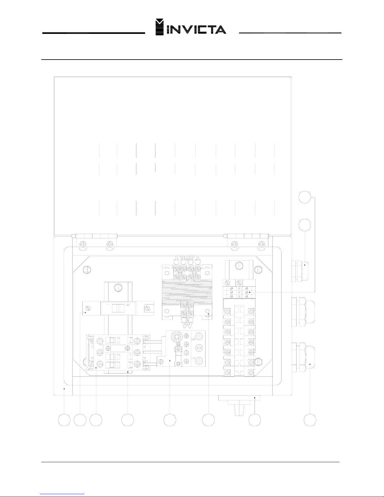
Electrical Protection equipment (page 09)
The machine can be optionally supplied with electrical overload protection. This equipment disconnects the motor
automatically when there is an electrical overload that could damage it. When the motor is disconnected, it is
necessary to reset the therrmal relay by pressing the reset button (point nº 02). Continue by pressing the start
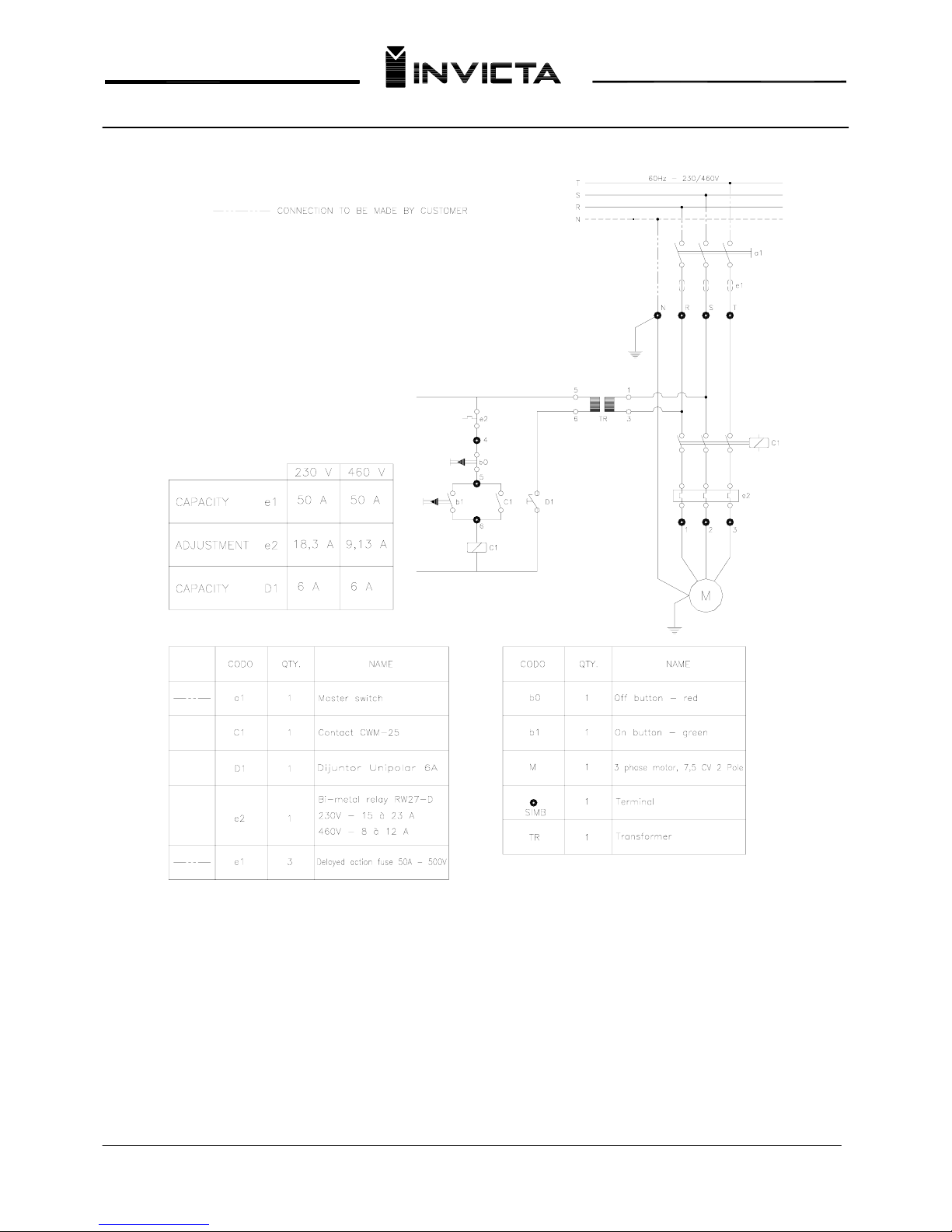
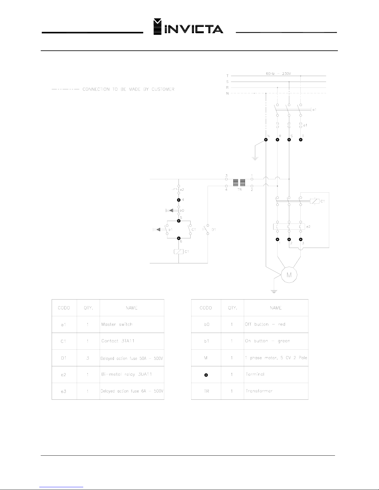
button. On pages 9 thru 12 are electrical diagrams for special motorization.
Machine Identification and Replacement Parts
Every INVICTA machine has a serial number which enables the manufacturer to identify the exact type and date of
its manufacture. At the end of this manual you will find a list of parts which compose your machine with their names
and numbers. Use only genuine INVICTA parts and on your order always mention the serial number, part number
and quantity desired.
Page 6

5
Table Saw
Mod. RT-40
Technical Data
Standard saw blade diameter……………………………….………………………………… mm 350 (14”)
Maximum saw blade diameter………………………………………………………………… mm 400 (16”)
Shaft diameter…………………………………………………………………………………… mm 30
Maximum cut (350 mm diameter saw)………………………………………………………... mm 115 (4-1/2”)
Maximum cut (400 mm diameter saw)…………………………..…………………………… mm 140 (5-1/2”)
Maximum height of cut at 45º (350 mm diameter saw)…………………………………….. mm 80 (3-1/8”)
Maximum height of cut at 45º (400 mm diameter saw)……….……………………………… mm 105 (4-1/8”)
Motor 3 / phase…………………………………....……………………………………………… HP 7,5
Shaft speed………………………………………………………………………………………. RPM 3000
Maximum dado capacity………………………………………………………………………... mm 40 (1-9/16”)
Maximum rip capacity……………………………………………………………………………. mm 850 (33-7/16”)
Distance from front of the table to center of the saw blade saw…………………………… mm 580 (22-13-16”)
Distance from front of table to the edge of a Ø 350 mm saw at maximum height………… mm 435 (17-1/8”)
Height from floor to table top………………………………………………………………….. mm 850 (33-7/16”)
Table dimensions……………………………………………………………………………….. mm
inch
1000 x 1000
39-3/8” x 39 –
3/8”
Table dimensions including 2 extensions…………………………………………………… mm 1500 x 1100
59” x 43-5/16”
Saw tilt to the right………………………………………………………………………………. º 45º
Approx. net weight with motor…………………………………………………………………. kg 543 (1195 Lbs)
Accessories
1 Special wrench
1 Instruction Manual
Page 7
6
Table Saw
Mod. RT-40
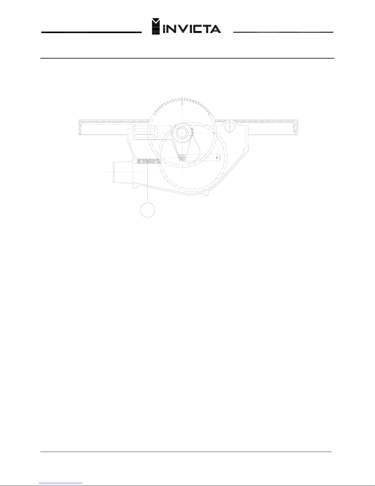
Instructions for replacing the Sawdust Guard
Your machine is equipped with a wooden guard (ballast) that helps to prevent sawdust from being blown up
through the table insert. This is a very important feature when dust collection is absent or very poor. Due to normal
wear it becomes necessary to change this guard, proceed as follows: Raise the saw blade to its maximum height,
remove the table insert. Replace the wooden guard with a new one of the same dimensions. Next, mount the new
piece of wood in the guard, and reassemble table insert. Turn the saw on and slowly lower it to its minimum height,
executing the cut in the wood. (Always lockout the power supply when doing blade maintenance)
A
Page 8
7
Table Saw
Mod. RT-40
Controls (Adjustment Features #1)
19 24 1718 16 15 14 11 12 09
13
08
07
10
03
06
0502
04 01
Page 9
8
Table Saw
Mod. RT-40
Controls (Adjustment Features #2)
26 25 23 18 2221
A
20
Page 10
9
Table Saw
Mod. RT-40
ELECTRICAL BOX
7
1
020103
04
A1
1 L1
A1
1- 2-
2 T1
05
06
A2
96 NC
PART. N°
11-28-00230
11-34-00120
11-07-00690
11-31-00070
8NAE-K205-0
11-20-00090
3 L2
A2
5 L3
3
NO
4NO
3-
4 T2
4-
6 T3
A2
95 NC97 NO98 NO
5
6
2
1
ITEM
3
4
1
3
2
4
5
6
Single phase transformer
NAME
Electrical box
Disjuntor C6A 5SX1-1
Contactor CWM25
1
QTY.
1
1
Track
Overload relay RW27D
1
2
1
07
12
56
08
11-03-00150
11-03-00090
11-02-00490
910
13 14
17 18
21 22
25 26
879
8
9
09
Press cable PG13.5
Press cable PG21
Borne terminal
2
1
1
10
10
11-04-00750
Switch electrical
Page 11
10
Table Saw
Mod. RT-40
Three – Phase Motor With overload Protection – 7,5HP – 230 / 460V
Page 12
11
Table Saw
Mod. RT-40
Single – Phase Motor with Overload Protection
Page 13
12
Table Saw
Mod. RT-40
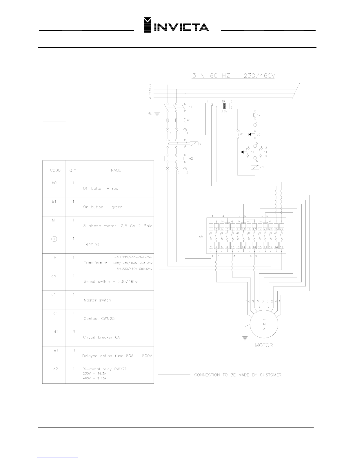
Select Switch – 230 / 460 V
IMPORTANT
SELECT THE VOLTAGE (230/460V) OF YOUR
INTERNAL ELECTRIC NETWORK.
THE VOLTAGE SELECTION KEY IS LOCATED ON
THE ELECTRICAL BOX.
FOR YOU SAFETY THE VOLTAGE SELECTION
KEY IS ON NEUTRAL POSITION.
Page 14
13
Table Saw
Mod. RT-40
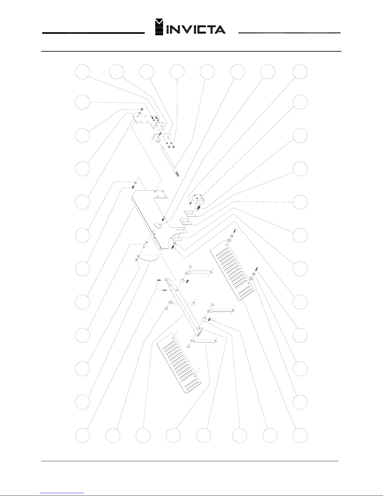
Replacement Parts (Blade Guard)
26
25
19
01
02
03
04
10
07
08 09 11 12 1413 15 16 17
05
06
24
23
22
21
20
18
3536 34 33 32 2831 30 29 27
Page 15
14
Table Saw
Mod. RT-40
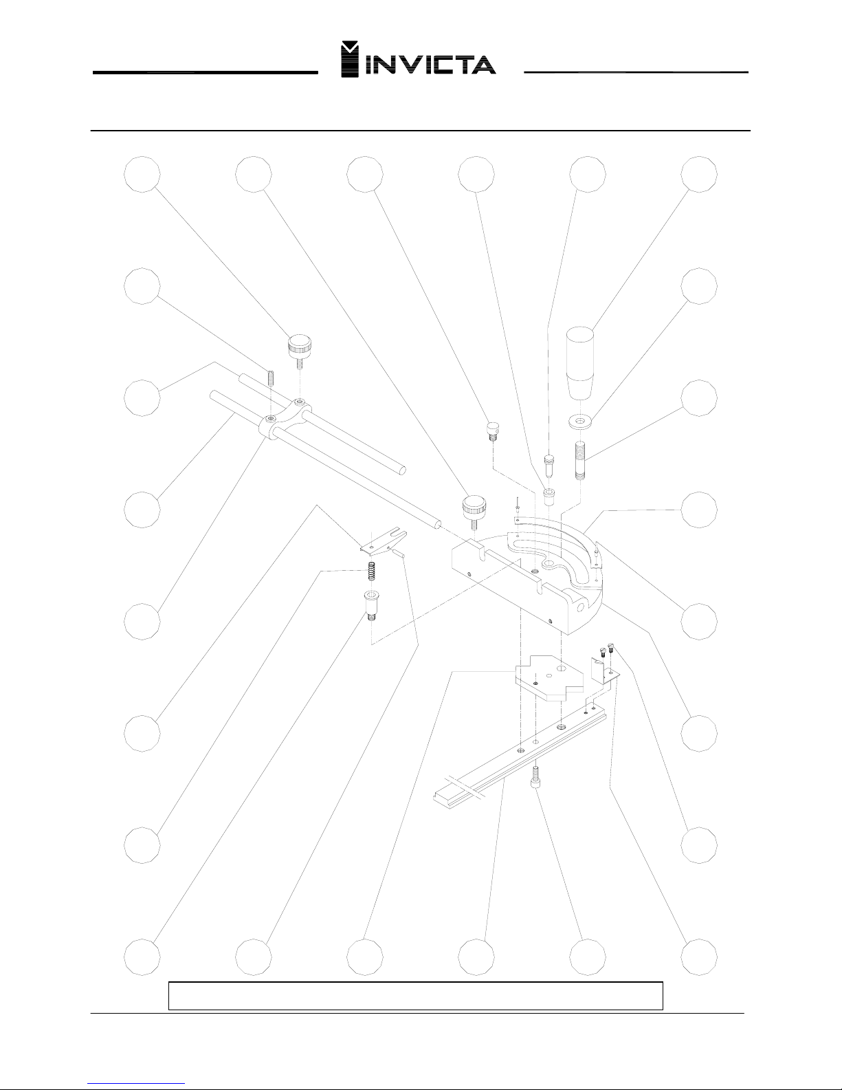
Replacement Parts (Miter Fence)
37
38
39
40
41
42
43
44 45
46
47
48 49
50
51
52
53
54
55
5657585960
Items 42-60 Assembly Part Number82SB-K039-0
Page 16
15
Table Saw
Mod. RT-40
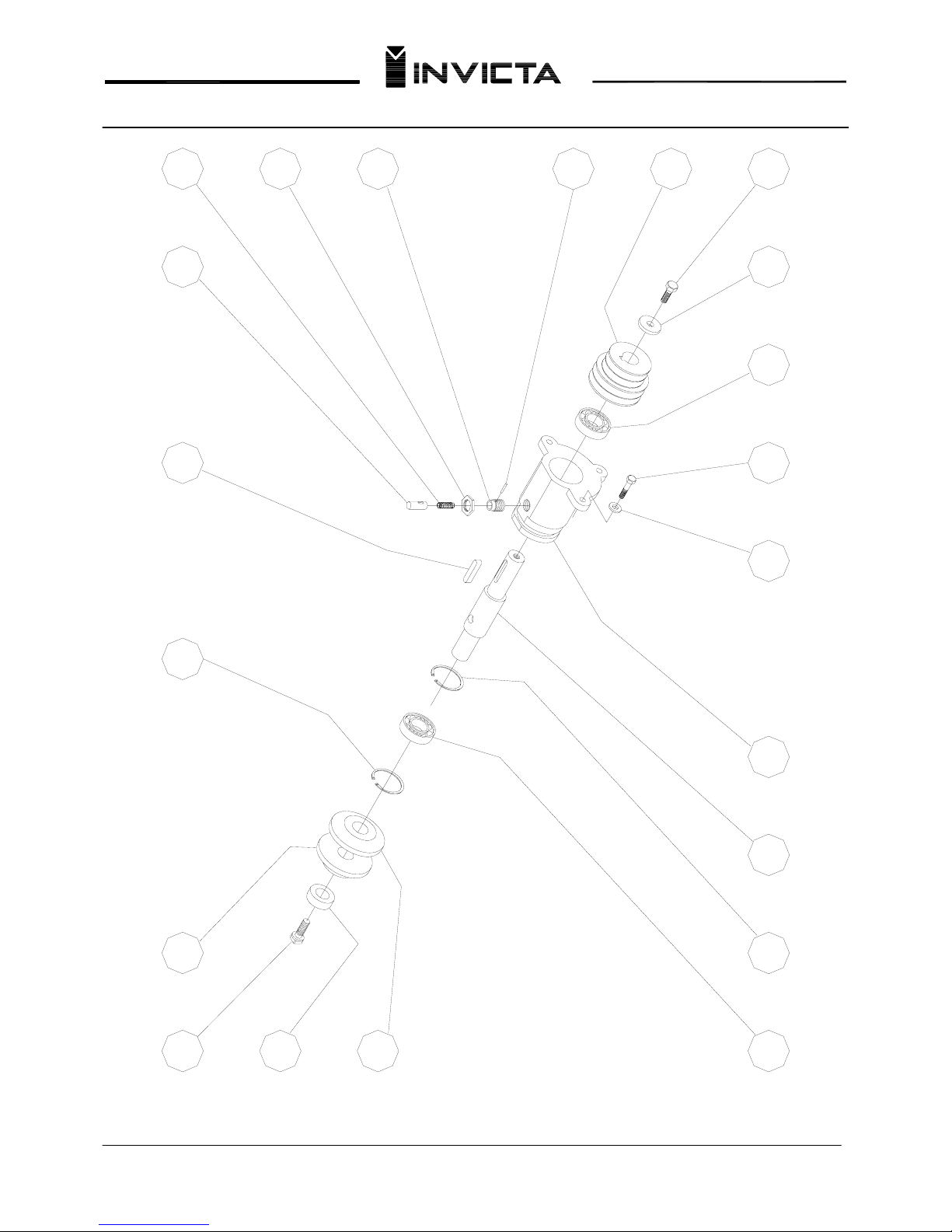
Replacement Parts (Saw Arbor)
62
61 85 83
63
79
82 8081
78
68 69 70
76
77
71 72 73
7574
73
Page 17
16
Table Saw
Mod. RT-40
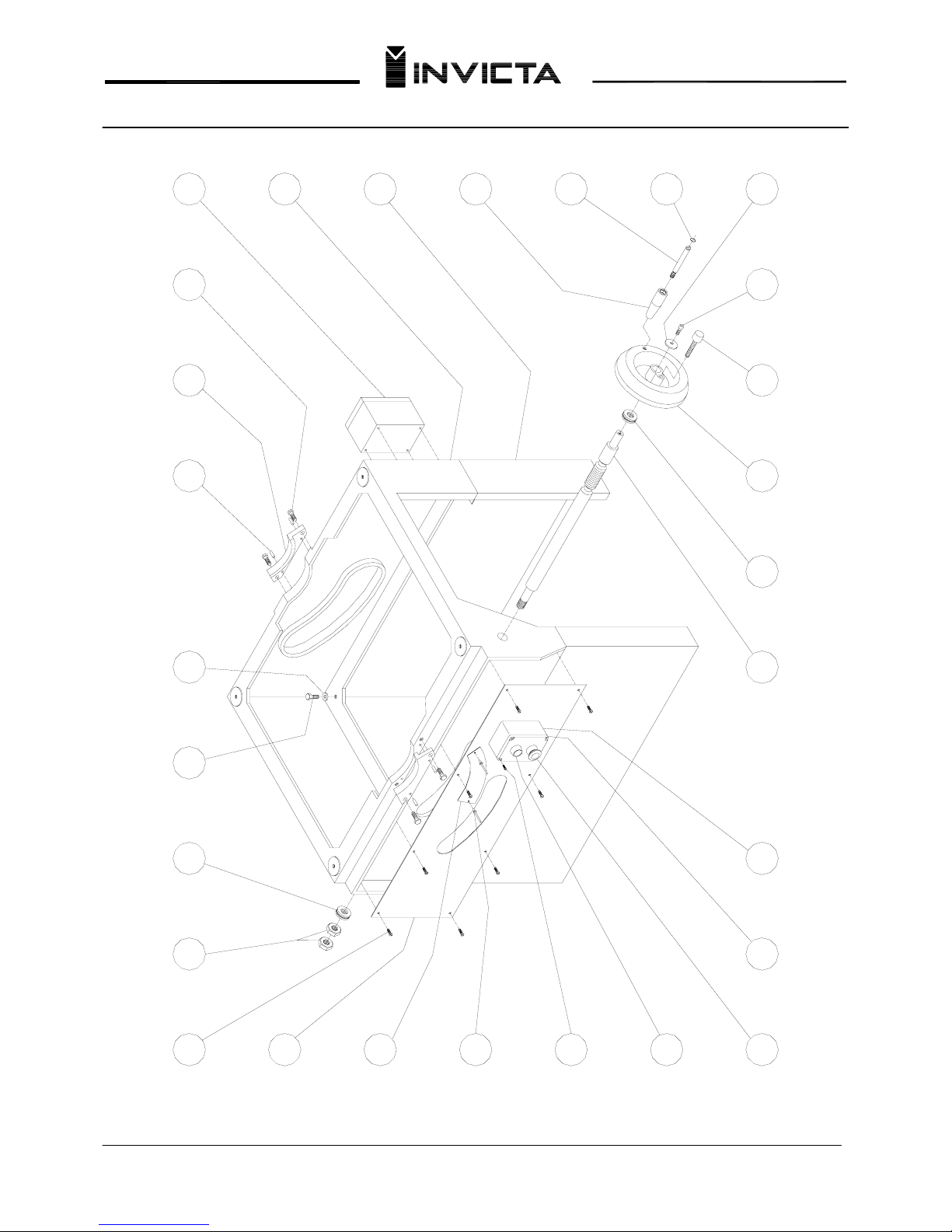
Replacement Parts (Saw Cabinet)
86
87
88
89
90
91
92 93 94 95 96 97 98 99
105
106107108109110111112113
104
103
102
101
100
Page 18
17
Table Saw
Mod. RT-40
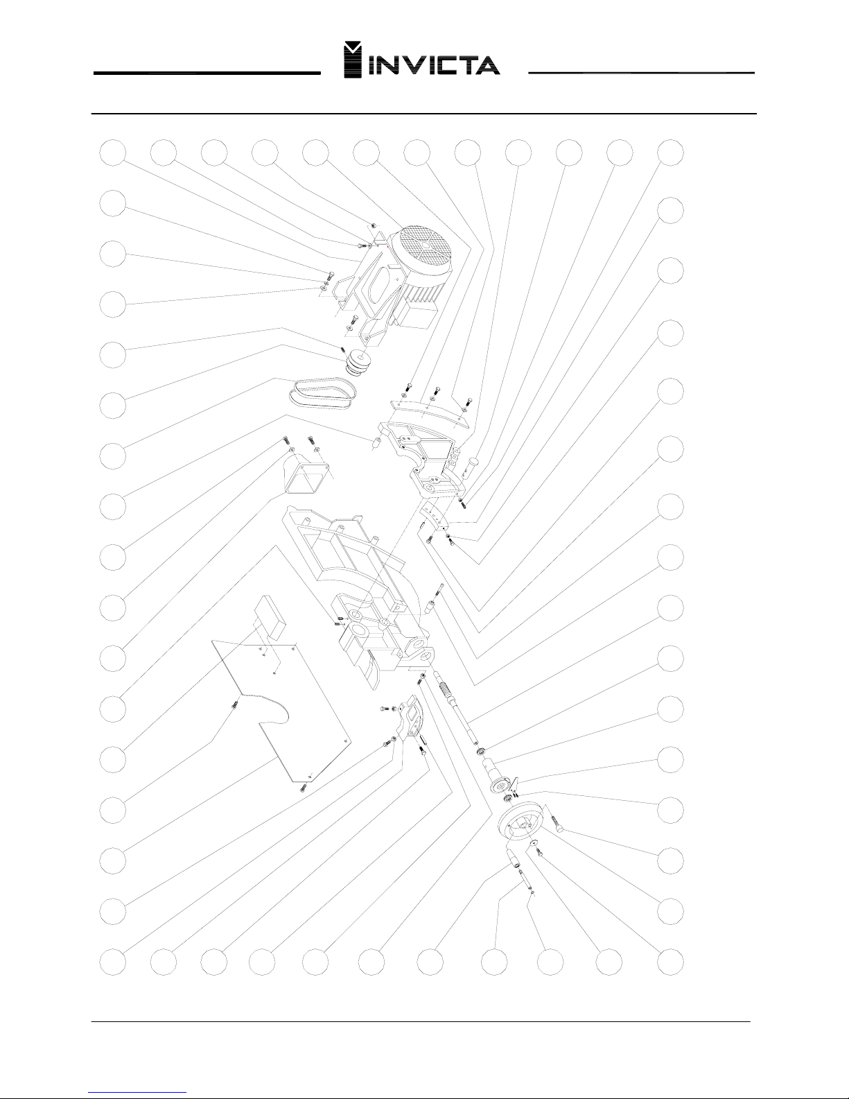
Replacement Parts (Saw Trunion and Motor)
125
165
119
124
122
123
120
121
117
118
114
115
116
127126 128 129 130 131 132 133
163164 162 161 160 159 158 157
134 135 136 137 138 139
142
140
141
143
144
152154
155156 153
145
146
147
151
148
149
150
Page 19
18
Table Saw
Mod. RT-40
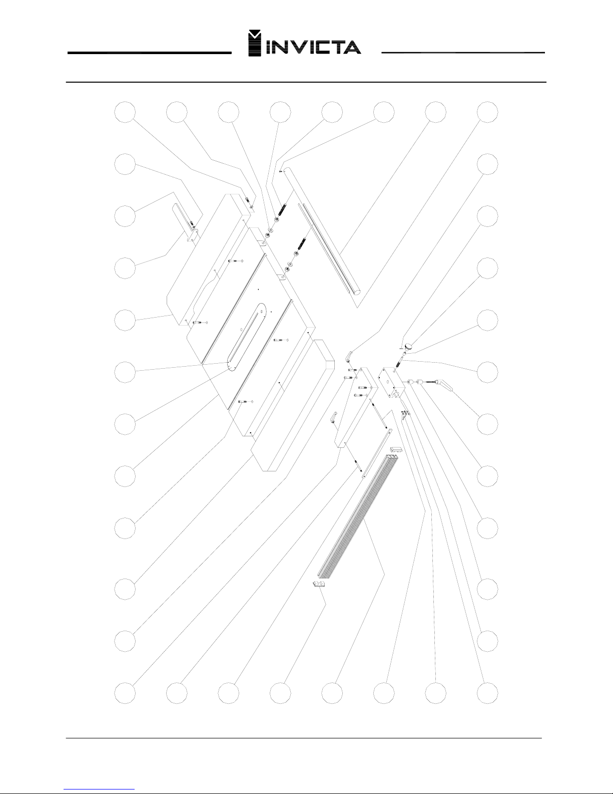
Replacement Parts (Saw Table Top and Rip Fence)
197166
167
168
196 195 194 193 192 191
190
189
170
171
172
173
174 175 179 180 181 182
188
187
186
185
183 184178177176
169
198199200201
Page 20

19
Table Saw
Mod. RT-40
Replacement Parts
FIG. Nº CODE QTY. NAME FIG. Nº CODE QTY. NAME
01.......... 06-03-0078-0 02…... Allen cap screw M6-1x12 35……... 06-18-0034-0 02….. Snap ring RS9
02.......... 82SB-K200-0 04…... Hinge pin screws 36……... 82SB-K194-0 02….. Kick back finger
03.......... 82SB-K193-0 01…... Guard bar 37……... 27-01-0038-0 01….. Knurled knob
04.......... 82SB-K191-0 04…... Guard arms 38……... 06-02-0053-0 01….. Allen
set screw head M6-1,0x10
05……... 26-03-0010-0 01…... Roll pin Ø8x80mm 39……... 8NVL-K181-0 01….. Repeat stop bar
06……... 82SB-K199-0 02…...
Hinge pin
40……... 8NVL-K182-0 01….. Repeat stop shaft
07……... 06-02-0068-0 04…... Allen
set screw M5-0,8x8 41……... 85SB-K125-0 01….. Repeat stop knuckle
08……... 82SB-K192-0 02…... Side plates * 42…... 82SB-K108-0 01….. Release lever
09……... 8NAR-K134-0 04…... Flat washer Ø30x12x1,9 * 43…... 07-00-0002-0 01….. Spring
10……... 82SB-K198-0 04…... Bushing * 44…... 89SB-KK97-0 01….. Shoulder bolt
11……... 06-06-0029-0 04…... Flat head screw M6-1x12 * 45…... 26-00-0006-0 01….. Roll pin Ø3x16
12……... 06-04-0121-0 02…... Hex head cap screw M10-1,5x30 * 46…... 82SB-KK93-0 01….. Pivot plate
13……... 06-13-0015-0 02…... Flat washer Ø10 mm * 47…... 82SB-K208-0 01….. Miter guide
14……... 82SB-K202-0 01…... Left spacer 3/16” * 48…... 06-03-0056-0 01….. Allen cap screw M5-0,8x12
15……... 82SB-K203-0 03…... Right inner spacer 1,52mm * 49…… 85SB-KK84-0 01….. Indicator bracket
16……... 82SB-K204-0 04…... Right outer spacer 0,9mm * 50…... 06-05-0053-0 02….. Round head screw M4-0,7X10
17……... 06-03-0081-0 02…... Allen cap screw
M10-1,5x40 * 51…... 89SB-KK92-0 01….. Miter guide
18……... 82SB-K201-0 01…... Guard block * 52…... 06-17-0002-0 02….. Pop ad 440s rivet
19……... 06-02-0055-0 02…... Allen set screw M8-1,25x20 * 53…... 85SB-KK86-0 01….. Graduated scale
20……... 89SB-K131-0 02…... Washer * 54…... 89SB-KK96-0 01….. Stud
21……... 06-03-0054-0 02…... Allen cap screw M6-1x10 * 55…... 06-13-0026-0 01….. Flat washer Ø10mm
22……... 82SB-K196-0 01…... Guard main shaft * 56…... 89SB-K125-0 01….. Lock knob
23……... 06-09-0019-0 02…... Hex nut M6-1,0 * 57…... 89SB-K106-0 01….. Guide pin
24……... 82SB-K188-0 01…... Shaft support * 58…... 89SB-K107-0 01….. Guide bushing
25……... 06-02-0054-0 01…... Allen set screw M8-1,25x10 * 59…... 89SB-K126-0 01….. Lever pin
26……... 06-13-0002-0 02…... Flat washer 1/4” * 60…... 27-00-0004-0 01….. Knurled knob
27……... 06-04-0096-0 02…... Hex head cap screw M6-1,0x25 61……... 82SB-K116-0 01….. Hex head bolt
28……... 06-09-0019-0 04…... Hex nut M6-1,0 62……... 82SB-K114-0 01….. Shaft end cap
29……... 06-13-0002-0 04…... Flat washer 1/4” 63……... 8NFL-KK34-0 01….. Inner saw flange
30……... 82SB-K197-0 01…... Support bracket 64……...
31……... 06-13-0002-0 04…... Flat washer 1/4" 65……...
32……... 06-04-0095-0 04…... Hex head cap screw M6-1,0x20 66……...
33……... 82SB-K185-0 01…... Guard base 67……..
34……... 82SB-K195-0 01…... Pin 68…….. 06-18-0017-0 01….. Snap ring I62
* 82SB-K039-0 Miter gauge assembly
Page 21

20
Table Saw
Mod. RT-40
FIG. Nº CODE QTY. NAME FIG. Nº CODE QTY. NAME
69…….. 82SB-K221-0 01….. Blade arbor 105…… 82SB-KKK2-0 01….. Upper saw base
70…….. 82SB-KKK9-0 01….. Bearing housing 106…… 11-28-0021-0 01….. Electrical connection box
71…….. 06-13-0015-0 03….. Flat washer Ø10mm 107…… 06-04-0121-0 04….. Hex head cap screw M10-1,5x30
72…….. 06-04-0098-0 03….. Hex head cap screw M10-1,5x35 108…… 82SB-KK11-0 02….. Saw trunion support
73…….. 03-00-0033-0 02….. Bearing 6206 2RS 109…… 26-02-0001-0 04….. Roll pin Ø6x20
74…….. 8NAR-K104-0 01….. Washer 110…… 8NAR-KK98-0 04….. Washer Ø25x10,5x3,1
75…….. 06-04-0099-0 01….. Hex head cap screw M12-
1,75x30
111…… 06-04-0125-0 04….. Hex head cap screw M10-1,5x20
76…….. 8NPM-K158-0 01….. Driven pulley 112…… 03-00-0060-0 01….. Bearing 51104
77…….. 26-00-0006-0 01….. Roll pin Ø3x16mm 113…… 8NPO-KK55-0 02….. Jam nut
78…….. 82SB-KK49-0 01….. Lock bushing 114…… 06-09-0020-0 02….. Hex nut M8x1,25
79…….. 82SB-K118-0 01….. Nut ** 115.. 82SB-KK22-0 01….. Tilt Adjustment Rack
80…….. 07-00-0030-0 01….. Spring 116…… 06-04-0097-0 02….. Hex head cap screw M10-1,5x25
81…….. 82SB-KK50-0 01….. Saw shaft lock 117…… 26-03-0011-0 02….. Roll pin Ø8x24
82…….. 8NCV-K257-0 01….. Key 118…… 82SB-KK71-0 01….. Saw trunion bracket
83…….. 06-18-0017-0 01….. Snap ring I62 119…… 06-09-0022-0 01….. Hex nut M12x1,75
84…….. 120…… 27-00-0003-0 01….. Handle
85…….. 8NFL-KK36-0 01….. Outer blade collar 121…… 8NPF-KK23-0 01….. Handle shaft
86…….. 06-05-0059-0 08….. Round head screw M6-1x16 122…… 06-18-0018-0 01….. Snap ring RS8
87…….. 10-03-0019-0 01….. Front panel 123…… 8NAR-KK81-0 01….. Washer Ø25x9x3,1
88…….. 82SB-KK32-0 01….. Tilt scale 124…… 06-03-0061-0 01….. Allen cap screw M8-1,25x30
89…….. 06-17-0003-0 02….. Pop AD 3,2 rivet 125…… 82SB-KK16-0 01….. Hand wheel
90…….. 06-05-0062-0 04….. Round head screw M4-0,7X16 126…… 8NPF-K22-0 01….. Lock screw
91…….. 11-27-0001-0 01….. Green ON Button 127…… 06-05-0043-0 02….. Round head screw M5-0,8X10
92…….. 11-27-0012-0 01….. Red OFF Button 128…… 82SB-KK63-0 01….. Saw tilt indicator
93…….. 82SB-KK96-0 01….. Switch box cover 129…… 82SB-KK17-0 01….. Hand wheel hub
94…….. 82SB-KK94-0 01….. Switch box 130…… 03-00-0060-0 02….. Bearing 51104
** 95…. 84SB-KK99-0 01….. Tilt adjustment shaft * 131... 82SB-KK69-0 01….. Elevation shaft
96…….. 03-00-0060-0 01….. Bearing 51104 132…… 82SB-KK52-0 01….. Pin
97…….. 82SB-K127-0 01….. Hand wheel 133…… 06-03-0033-0 01….. Allen cap screw M8-1,25x70
98…….. 8NPF-KK25-0 01….. Lock screw 134…… 26-03-0011-0 02….. Roll pin Ø8x24
99…….. 06-03-0061-0 01….. Allen cap screw M8-1,25x30 135…… 06-04-0098-0 02….. Hex head cap screw M10-1,5x35
100…… 8NAR-KK81-0 01….. Flat washer Ø25x9x3,1 136…… 06-04-0088-0 01….. Hex head cap screw M8-1,25x40
101…… 06-18-0018-0 01….. Snap ring RS8 137…… 06-09-0020-0 01….. Hex nut M8-1,25
102…… 8NPF-KK23-0 01….. Handle shaft * 138…. 82SB-KK23-0 01….. Vertical movement bracket
103…… 27-00-0003-0 01….. Handle 139……. 06-02-0081-0 01….. Allen set screw M6-1x30
104…… 82SB-KK81-0 01….. Lower saw base 140……. 06-09-0029-0 01….. Hex nut ½” unc
* 82SB-2077-0 Blade height screw/rack assembly (131 & 138) ** 82SB-2078-0 Blade angle screw/rack assembly (95 & 115)
Page 22

21
Table Saw
Mod. RT-40
FIG. Nº CODE QTY. NAME FIG. Nº CODE QTY. NAME
141…… 82SB-KK67-0 01….. Pin 177…… 82SB-K220-0 01….. Outer spacer
142…… 82SB-KKK7-0 01….. Saw support 178…… 8NCA-KK34-0 01….. Adjustable lock handle
143…… 06-13-0015-0 03….. Flat washer Ø10mm 179…… 82SB-KK42-0 01….. Stud
144…… 82SB-KK25-0 03….. Support plate 180…… 82SB-K212-0 01….. Bushing
145…… 06-04-0069-0 01….. Hex head cap screw M10-1,5x80 181…… 8NMN-KK79-0 01….. Knob
146…… 29-34-0010-0 01….. Motor 7,5 hp 182…… 26-00-0002-0 01….. Roll pin Ø3x24
147…… 06-09-0021-0 04….. Hex nut M10-1,5 183…… 27-00-0011-0 02….. Adjustable lock handle
148…… 06-13-0015-0 04….. Flat washer Ø10mm 184…… 82SB-K227-0 01….. Rip fence scale
149…… 06-04-0089-0 04….. Hex head cap screw M10-1,5x50 185…… 82SB-K213-0 01….. Rip fence guide bar
150…… 82SB-KK97-0 01….. Motor base plate 186…… 06-17-0002-0 01….. Pop 440S rived
151…… 06-30-0103-0 02….. Allen cap screw M12-1,75x45 187…… 8NVR-K101-0 02….. Threaded rod
152…… 06-13-0024-0 02….. Washer 188…… 06-09-0001-0 04….. Hex nut M16-2
153…… 8NAR-KK85-0 01….. Washer Ø30x13x4 189…… 06-13-0006-0 02….. Flat washer Ø5/8”
154…… 06-02-0054-0 01….. Allen set screw M8-1,25x10 190…… 06-13-0015-0 06….. Flat washer Ø10mm
155…… 8NP-K159-0 01….. Motor pulley 191…… 06-04-0098-0 06….. Hex head cap screw M10-1,5x35
156…… 15-00-0020-0 02….. Correia VA-26 series “V” belt 192…… 06-13-0015-0 02….. Flat washer Ø10mm
157…… 82SB-KKK8-0 03….. Spacer 193…… 06-04-0121-0 02….. Hex head cap screw M10-1,5x30
158…… 06-05-0040-0 02….. Round head screw M8-1,25X20 194…… 82SB-K102-0 01….. Rip fence extension bar
159…… 06-13-0025-0 02….. Flat washer Ø8mm 195…… 82SB-KKK5-0 01….. Table extension
160…… 82SB-KK24-0 01….. Chip duct 196…… 06-02-0053-0 04….. Allen set screw M6-1x10
161…… 06-02-0061-0 02….. Allen set screw M10-1,5x16 197…… 82SB-K210-0 01….. Table insert plate
162…… 82SB-KK79-0 01….. Upper chip deflection plate 198…… 82SB-KKK3-0 01….. Cast table
163…… 06-23-0001-0 02….. Screw 199…… 06-02-0054-0 04….. Allen set screw M8-1,25x10
164…… 82SB-KK62-0 01….. Trunion plate 200…… 82SB-KKK4-0 01….. Table extension
165…… 06-04-0088-0 02….. Hex head cap screw M8-1,25x40 201…… 06-03-0068-0 04….. Allen cap screw M10-1,5x50
166…… 82SB-KK18-0 01….. Rip fence cast base
167…… 8NPW-K501-0 01….. Threaded rod (short)
168…… 82SB-KK41-0 01….. Rip fence lock bar
169…… 21-88-0085-0 02….. Aluminum rip fence caps
170…… 82SB-KK30-0 01….. Aluminum rip fence
171…… 8NPW-K502-0 01….. Threaded rod (long)
172…… 82SB-K215-0 01….. Scale pointer
173…… 06-06-0028-0 02….. Flat head screw M4-0,7x10
174…… 82SB-KK43-0 01….. Support pin
175…… 82SB-K218-0 01….. Rip fence block
176…… 82SB-K219-0 01….. Inner spacer
Page 23
 Loading...