

Page 1

ADJUSTABLE LEISURE BED
Economy Models:
LBET, LBEF and LBEQ
Deluxe Models:
LDBT, LBDF and LBDQ
OWNER'S ASSEMBLY AND
OPERATING MANUAL
Page 2

SPECIAL NOTES
DO NOT OPERATE THIS EQUIPMENT WITHOUT FIRST READING AND
S
P
E
C
I
A
L
N
O
T
E
S
UNDERSTAND THE WARNINGS, CAUTIONS, AND INSTRUCTIONS,
CONTACT A HEALTHCARE PROFESSIONAL, DEALER OR TECHNICAL
PERSONNEL IF APPLICABLE BEFORE ATTEMPTING TO USE THIS
EQUIPMENT - OTHERWISE INJURY OR DAMAGE MAY RESULT.
DANGER/WARNING/CAUTION notices used in this manual apply to hazards or unsafe practices which could result in personal injury and/or property damage.
WARNING
UNDERSTANDING THIS MANUAL. IF YOU ARE UNABLE TO
SPECIAL NOTES
NOTICE
The information contained in this document is subject to change without notice.
Check all parts for shipping damage and test before using. In case of damage, do NOT
use. Contact the Dealer for further instruction.
WARNING
This bed is for residential use only. This bed is NOT for hospital use and was not designed to
meet hospital standards.
DO NOT use this bed outdoors.
DO NOT use near explosive gases.
Possible fire hazard when used with oxygen administering equipment other than nasal or
masked type.
DO NOT use this bed with an oxygen tent.
When using nasal or masked type administering equipment, oxygen or air tubing MUST be
routed and secured properly to ensure that tubing does NOT become entangled and
damaged during normal operation of the bed.
When using liquids in or around the bed, caution should be taken to ensure that liquids of
any kind are not spilled. If a liquid is spilled in or around the bed, stand in a dry area and
UNPLUG the bed immediately. Clean up spill and allow bed or area around bed to dry
thoroughly before using the electric controls again.
DO NOT use bed rails with this bed.
Close supervision is necessary when this product is used by or near CHILDREN OR INDI-
VIDUALS WITH DISABILITIES.
NEVER PERMIT ANYONE UNDER THE BED AT ANY TIME.
When operating/moving beds, ALWAYS ensure that the individual utilizing the bed is positioned properly within the confines of the bed. DO NOT let any extremities protrude over
the side of the bed when performing these functions.
2
Page 3

TABLE OF CONTENTS
TABLE OF CONTENTS
SPECIAL NOTES ................................................................................................................................2
SAFETY SUMMARY............................................................................................................................4
T
A
B
L
E
SPECIFICATIONS ...............................................................................................................................5
ASSEMBLY..........................................................................................................................................6
Preparation ......................................................................................................................................6
Installing Locking Casters ................................................................................................................6
Installing Mattress Retainer Bar .......................................................................................................6
Connecting Pendant ........................................................................................................................6
Installing Mattress ............................................................................................................................6
Installing a Head Board ....................................................................................................................6
Removing Adjustable Head Board Brackets....................................................................................6
OPERATING ........................................................................................................................................8
Operating Bed .................................................................................................................................8
Locking/Unlocking Casters ..............................................................................................................8
Mattress ...........................................................................................................................................9
Manually Lowering Head/Foot End of Bed ....................................................................................... 9
O
F
C
O
N
T
E
N
T
S
TROUBLESHOOTING .....................................................................................................................10
FREQUENCY CHANNEL/BATTERY .................................................................................................11
Changing Frequency Channel ......................................................................................................... 11
Replacing Battery ........................................................................................................................... 11
3
Page 4

SAFETY SUMMARY
OPERATING INFORMATION
S
A
F
E
T
Y
S
U
M
M
A
R
Y
After bed has been assembled, always test to make sure that all sections of the bed are
properly and securely in place BEFORE using.
Keep ALL moving parts free of obstruction (i.e. blankets/sheets, heating blankets/pads, tubing,
wiring, etc. and other types of products using electric cords which may get tangled around
the bed or legs) during operation of Electric beds.
Trapeze units MUST be positioned on floor stand; as near as possible to the center point of the
bed. The trapeze is to be used ONLY in ASSISTING the patient in repositioning or transferring in
or out of bed.
Use ONLY free standing Traction units with these model beds. These units are to be used ONLY
for immobilizing a patient in various traction setups or ASSISTING the patient in repositioning or
transferring in or out of bed.
NEVER allow patients to use trapeze or traction units as a total individual weight support.
Make certain ALL screws and nuts are tight at all times.
Leisure beds are equipped with four (4) locking casters. ALWAYS engage all four (4) locking
casters EXCEPT when moving the bed. Inspect for correct locking action on wheel locks
BEFORE using bed.
Body weight MUST be evenly distributed over the surface of the bed. DO NOT lay, sit or lean
in such a way that entire body weight is placed only on RAISED head or foot ends of bed. This
includes when assisting in repositioning or transferring in or out of bed.
USING TWO (2) TWIN BEDS AS A KING SIZE BED - When put together to form a king size bed, a
gap will exist between the two (2) twin beds. Make sure all four (4) locking casters of each
bed are engaged BEFORE using the bed, otherwise the two (2) twin beds may move apart,
possibly causing injury and/or damage.
USING TWO (2) TWIN BEDS AS A KING SIZE BED - The pendant functions of the two (2) twin beds
will operate separately. BEFORE changing the position of EITHER bed, confirm the area between
the two (2) twin beds is clear. Otherwise, individuals may become entangled between the
two (2) twin beds, possibly causing injury and/or damage.
SAFETY SUMMARY
WARNING
ELECTRICAL - GROUNDING INSTRUCTIONS:
A. This product MUST be grounded. In the event of an electrical short circuit, grounding
reduces the risk of electric shock by providing an escape wire for the electrical current.
This product is equipped with a cord having a grounding wire with a grounding plug. The
plug must be plugged into an outlet that is properly installed and grounded. DO NOT
bypass the grounding plug.
Improper use of the grounding plug can result in a risk of electrical shock.
Check with a qualified electrician or serviceman if the grounding instructions are not com-
pletely understood, or if doubt exists as to whether the product is properly grounded.
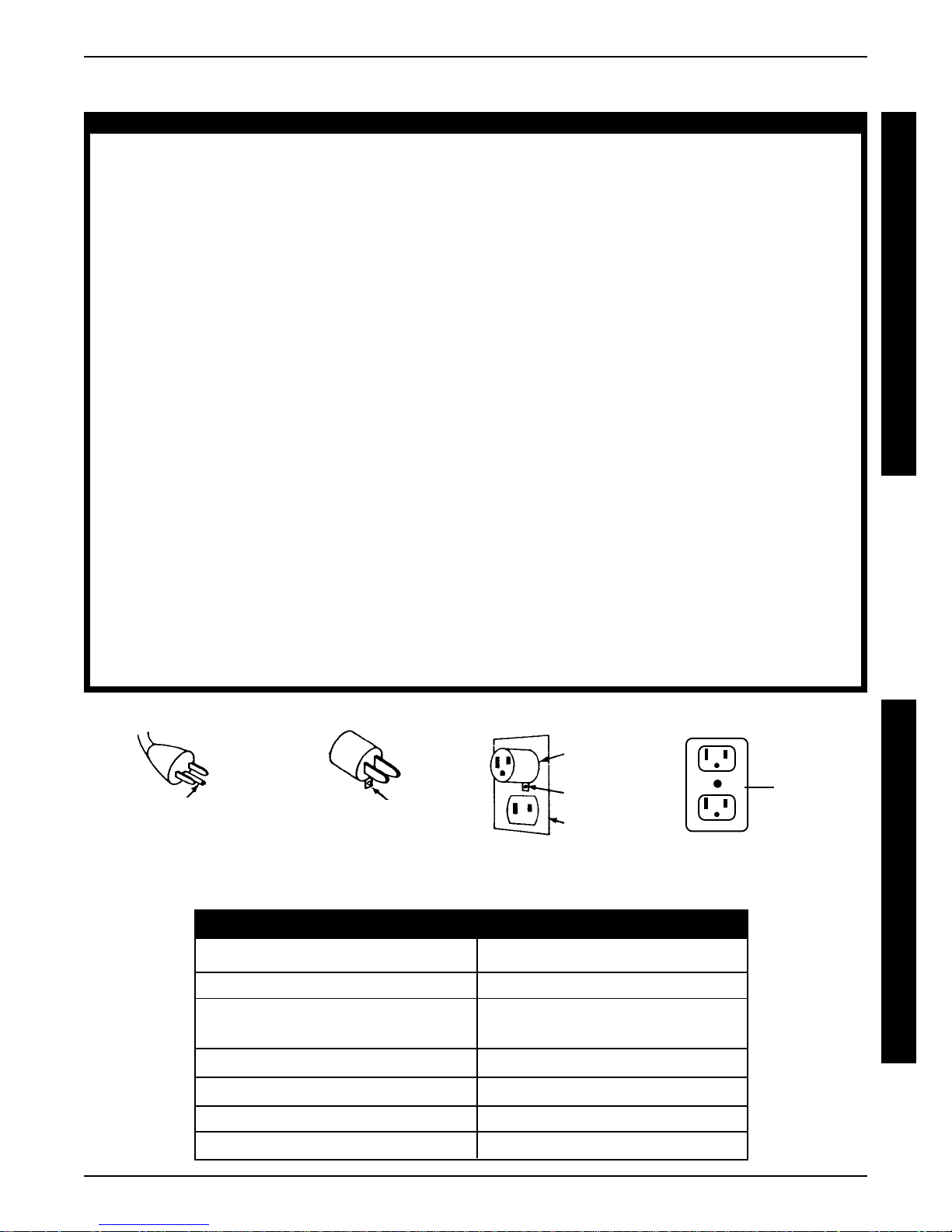
B . This product is for use on a normal 120 VAC circuit and has a grounding plug that looks like
the plug illustrated in sketch A shown at the bottom of this page. A temporary adapter,
which looks like the adaptor illustrated in sketches B and C, may be used to connect this
plug to a 2-pole outlet as shown in sketch C if a properly grounded outlet is not available.
The temporary adaptor should be used only until a properly grounded outlet (sketch D)
can be installed by a qualified electrician. The rigid ear, lug and the like extending from the
adapter MUST be connected to a permanent ground such as properly grounded outlet
box cover. Whenever the adapter is used, it MUST be held in place by the screw.
NEVER operate if the unit has a damaged cord or plug. If it is not working properly, call
Qualified Service Personnel for examination and repair.
DANGER
4
Page 5
SAFETY SUMMARY (continued)
WARNING
Keep all cords away from HEATED or HOT surfaces.
SAFETY SUMMARY/SPECIFICA TIONS
WIRELESS PENDANT
This equipment has been tested and found to comply with the limits for a Class B digital
device, pursuant to Part 15 of the FCC rules. These limits are designed to provide reasonable protection against harmful interference in a residential installation. This equipment
generates, uses and can radiate radio frequency energy, and if not installed and used in
accordance with these instructions, may cause harmful interference to radio or television
reception, which can be determined by turning the equipment off and on, the user is
encouraged to try one or more of the following measures:
● ●
● Reorient or relocate the receiving antenna
● ●
● ●
● Increase the separation between the pendant and the bed.
● ●
● ●
● Consult the dealer or an experienced technician for help.
● ●
REPAIR OR SERVICE INFORMATION
DO NOT open assemblies such as the motors, pendant, junction boxes or electrical control
boxes. ONLY trained service personnel certified by Invacare are qualified to repair these
parts. If uncertified individuals perform any work on these beds, the warranty is voided.
DO NOT use unauthorized parts, accessories, or adapters other than those authorized by
Invacare.
UNPLUG the power cord when performing any maintenance on the bed.
WEIGHT LIMITATION
The weight limitations for Invacare Leisure Beds; taking into consideration patient size,
proper positioning, realignment, transfer and overall care are; Twin Size - 250 pounds,
Full Size - 340 pounds and Queen Size - 425 pounds (weight distributed evenly over
entire bed surface).
S
A
F
E
T
Y
S
U
M
M
A
R
Y
AB
Grounding Pin
Rigid Ear
SPECIFICATIONS
NOTE: All specifications are approximate.
OVERALL WIDTH - in inches
OVERALL LENGTH - in inches
BED HEIGHT - in inches
(Floor to top of Mattress)
HEAD ANGLE RANGE
FOOT ANGLE RANGE
WEIGHT - in pounds
SHIPPING WEIGHT - in pounds
CD
Adapter
Metal Screw
Grounded
Outlet Box
TWIN FULL QUEEN
36 53 60
80 80 80
26 26 26
o
-85
0
0o-70
o
o
0o-85
0o-70
o
0o-85
o
0o-70
225 270 290
233 278 300
S
P
Grounded
Outlet
E
C
I
F
I
C
A
T
I
O
N
S
o
o
5
Page 6

ASSEMBLY
ASSEMBLY
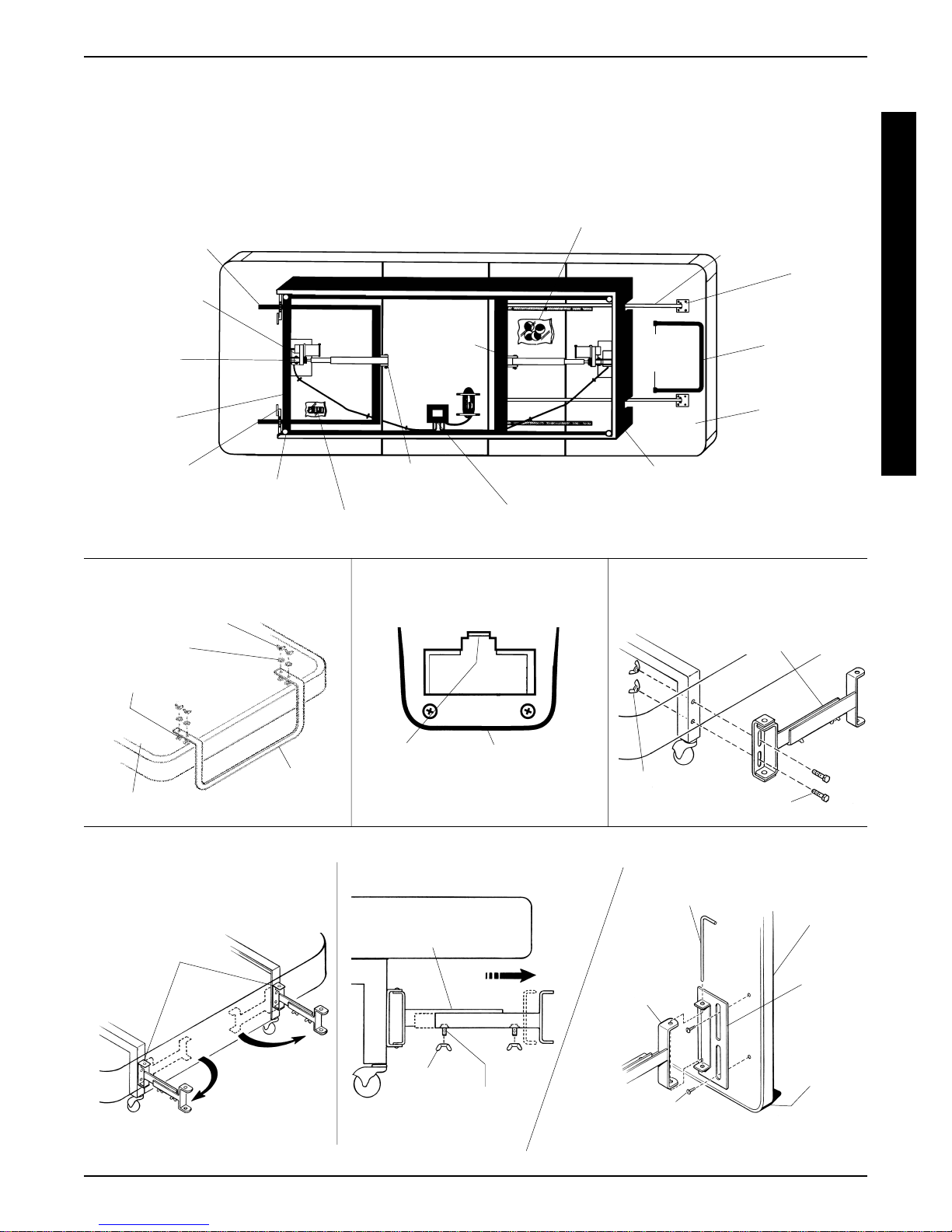
ASSEMBLY (FIGURE 1)
Preparation
1. Remove the following from the bottom of the bed:
A
S
S
E
M
B
L
Y
A. Four locking (4) casters in a plastic bag.
B. Pendant in a plastic bag.
C. Banding that secures the power cord, pendant cord
(economy model beds only), mattress retainer bar
and foot end of bed to bed base.
NOTE: Deluxe Model Beds - If a head board is not being
used, remove the adjustable head board brackets. Refer to
REMOVING ADJUST ABLE HEAD BOARD BRACKET
in this section of the manual.
NOTE: Deluxe Model Beds - If two (2) twin beds are being
used together with a king size head board, only the two (2)
OUTSIDE adjustable head board brackets will be used.
The two (2) INSIDE adjustable head board brackets should
be removed. Refer to REMOVING ADJUSTABLE
HEAD BOARD BRACKET in this section of the manual.
NOTE: Deluxe Model Beds - If two (2) twin beds are being
used together as a king size bed, the frequency channels
of the pendants can be set so the two (2) twin beds will
operate with one (1) pendant.Refer to CHANGING FRE-
QUENCY CHANNEL in the FREQUENCY CHANNEL/
BA TTERY section of this manual.
Installing Locking Casters
1. Position the stem of one (1) locking caster with the one
(1) of the caster sockets at the head or foot end of bed.
WARNING
Make sure the locking casters are secured to the bed frame, otherwise injury
or damage may occur.
2. Install the stem of the locking caster into the caster socket
until an audible "click" is heard. Make sure the caster
retaining ring enters the caster socket squarely and the
caster is secured to the bed frame.
3. Repeat STEPS 1-2 for the remaining casters.
WARNING
Removing bed from carton requires two
(2) people, otherwise injury or damage
may occur.
4. Remove bed from the bottom half of the shipping carton.
5. Set the bed onto all four (4) locking casters.
Installing Mattress Retainer Bar
1. Remove plastic sleeve from the mattress retainer bar.
2. Install mattress retainer bar onto the four (4) studs on the
underside of the bed as shown in FIGURE 1.
3. Install the four (4) washers and wing nuts onto the four
(4) threaded studs and tighten securely.
Connecting Pendant
NOTE: This procedure is for economy model beds only.
1. Remove the back plate of the pendant.
2. Plug the pendant cord from the electrical control box
into the plug in the pendant.
3. While holding the pendant cord in the slot on the pendant, reinstall the back plate.
Installing Mattress
CAUTION
Protective covers MUST be removed to
ensure proper ventilation and avoid the
possibility of mildew and musty odors.
1. Remove protective cover from base and mattress.
2. Place the mattress on the base.
NOTE: The mattress may be placed onto the bed either
side up and may be turned and rotated head to foot.
Installing a Head Board
NOTE: Head boards can be assembled onto deluxe
model beds only.
NOTE: Deluxe Leisure Beds are designed to be used
with your head board.
CAUTION
The head board MUST rest on the floor.
Adjustable head board brackets are not
designed to support the full weight of the
head board.
1. Swing the two (2) adjustable head board brackets
(attached to the bed) to the open position as shown in
FIGURE 1.
2. Remove the two (2) wing nuts and mounting screws
that secure the two pieces of the adjustable head board
bracket together.
3. Adjust length of the adjustable head board bracket
until the end of bracket clears the end of the mattress.
4. Reinstall the two (2) mounting screws that secure the
two pieces of adjustable head board bracket together.
5. Reinstall the two (2) wing nuts and tighten securely.
6. Attach a metal plate to the head board using the existing head board hardware.
7. Line up the mounting holes in the metal plate with the
mounting holes in the adjustable head board bracket
and insert a steel pin through all four (4) holes.
8. Repeat STEPS 2-7 for opposite head board bracket.
6
Page 7
Removing Adjustable Head Board Bracket
1. Remove the mounting screws and wing nuts that secure adjustable head board bracket to bed frame.
2. Remove adjustable head board bracket from bed frame.
NOTE: Save head board brackets for future use.
Lift Tube Assembly
Massage
Motor (Deluxe
Models Only)
Lift
Support
Lift Motor
Band
ASSEMBLY
Locking Casters (In Plastic Bag)
THIGH FOOTSTATIONARYHEAD
Lift Rod
Lift Plate
Mattress
Wing
Nuts
Retainer
Bar
A
S
S
E
M
B
L
Y
Bed Frame
Adjustable Head
Board Bracket
(Deluxe Models
Only)
INSTALLING MATTRESS
RETAINER BAR
Wing Nuts
Washers
Threaded Studs
Underside of Bed
Locking
Caster
Socket
Mattress
Pendant (in
Plastic Bag)
(ECONOMY MODELS ONLY)
Pin
Electrical Control Box (Serial Number
and Frequency Channel Sticker)
CONNECTING PENDANT
Plug
Back of
Pendant
Retainer Bar
INSTALLING A HEAD BOARD (DELUXE MODELS ONLY)
Clevis/Hitch
Woodgrained Base Box
(Deluxe Models Only)
REMOVING ADJUSTABLE
HEAD BOARD BRACKET
Wing
Nuts
Plywood
Platform
Adjustable Head
Board Bracket
Mounting Screws
STEP 1 STEPS 2-5
Adjustable Head
Board Brackets
(Supplied)
Adjustable Head
Board Bracket
Wing Nuts
Mounting
Screws
FIGURE 1 - ASSEMBLY
7
STEPS 6-7
Steel Pin (Supplied)
Adjustable
Head Board
Bracket
Head Board Mounting
Hardware (Not Supplied)
Head
Board
Metal
Plate
(Supplied)
Floor
Page 8
OPERATING
OPERATING BED
WARNING
DO NOT lay, sit or lean in such a way that
O
P
E
R
A
T
N
G
entire body weight is placed on the head
or foot end of the bed while raising or lowering - otherwise injury or damage may
occur.
CAUTION
Make sure the movement of the bed is free
I
from obstruction.
DO not pull the bed by the power cord.
ALWAYS unplug the bed BEFORE moving.
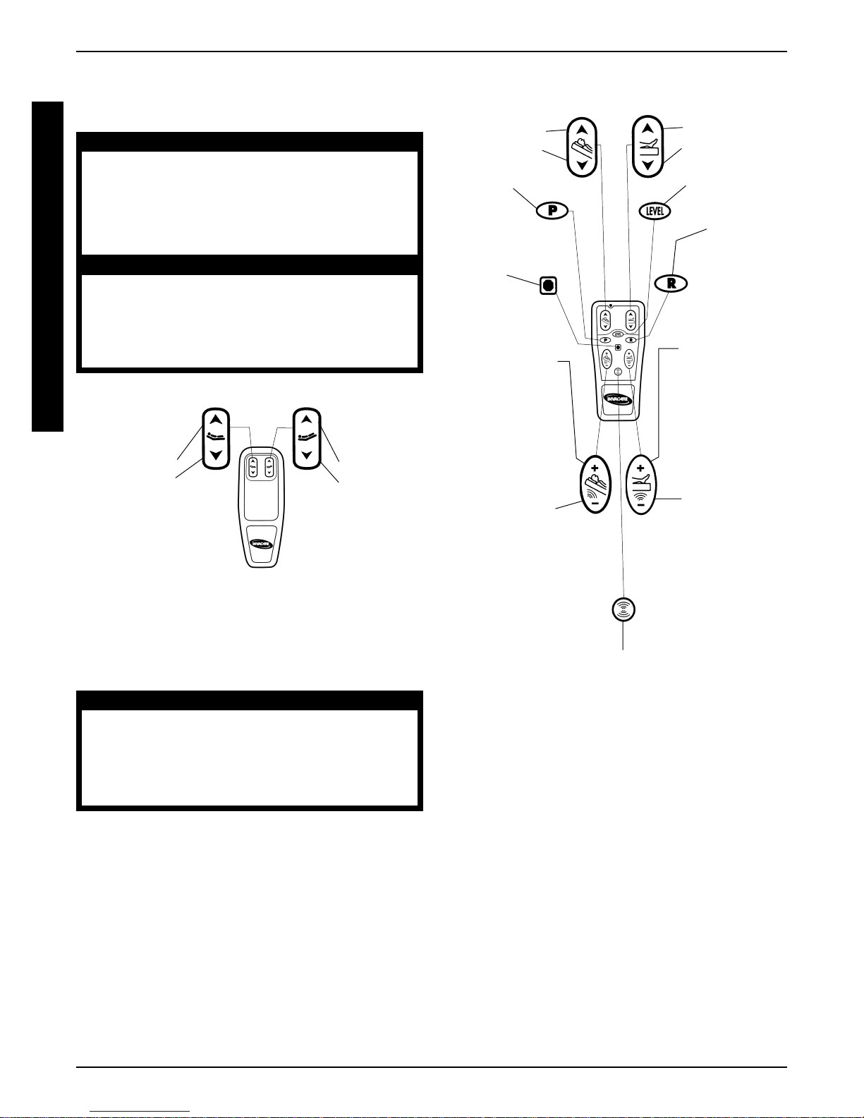
Economy Leisure Bed Pendant (FIGURE 1)
Press and
Hold to:
Raise Head
Lower Head
FIGURE 1 - OPERATING BED - ECONOMY
LEISURE BED PENDANT
OPERATING
Press and Hold to
Raise Head
Lower Head
Press to
Program
Desired
Position
Press to
Stop All
Programs
Press and Hold to
Increase Head
Massage Intensity.
When using
Press and
Hold to:
Raise Foot
Lower Foot
Neurosage Wave
Action, press to
Increase Massage
Lower Head
Massage Intensity.
When using
Neurosage Wave
Action, press to
Decrease Massage
Intensity
Intensity
Press and Hold to
Raise Foot
Lower Foot
Press to
Return
to Flat Position
Press to
Recall Position
Set by Program
Button
Press and Hold to
Increase Foot
Massage Intensity.
When using
Neurosage Wave
Action, press to
Increase Wave
Action Speed
Lower Foot
Massage Intensity.
When using
Neurosage Wave
Action, press to
Decrease Wave
Action Speed
Deluxe Leisure Bed Pendant (FIGURE 2)
CAUTION
Two (2) deluxe beds in the same room cannot be operated at the same time. If the
pendants of both beds are sending command signals at the same time, they will interfere with each other.
NOTE: The head and foot ends of the bed cannot be operated at the exact same time (unless using the level button ).
NOTE: Before using the massage, raise the head and
foot ends approximately 1/2-inch off of the bed frame.
Otherwise the bed may make excessive noise.
NOTE: Once the Massage system is activated, it will automatically change to the last massage setting used and
will shut off in thirty (30) minutes. To restart the massage
action, press the neurosage button.
Press to
Start Neurosage
Wave Action
FIGURE 2 - OPERATING BED - DELUXE
LEISURE BED PENDANT
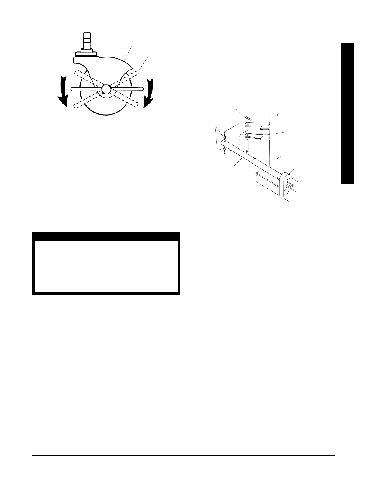
LOCKING/UNLOCKING CASTERS
(FIGURE 3)
1. Perform one (1) of the following:
LOCKING - Toggle the locking lever on the four (4)
locking casters to the LOCKED position.
UNLOCKING - Toggle the locking lever on the four
(4) locking casters to the UNLOCKED position.
8
Page 9
OPERATING
Locking Caster
Locking
Lever
FIGURE 3 - LOCKING/UNLOCKING CASTERS
MATTRESS
A new mattress will take a few days to contour to the
shape of the bed. Mattresses are made to be used on
both sides and should be turned every sixty (60) days
during the first year. After the first year, the mattress should
be turned two (2) or three (3) times a year.
3. With one (1) person holding the head/foot end of the
bed UP, remove the clevis and hitch pin that secure
the motor to the bed frame.
4. Set the drive shaft of the motor on the floor.
5. Gently lower the head/foot end of the bed down.
6. Reverse STEPS 3-5 to reassemble the bed. Refer
to FIGURE 4 for hardware orientation.
Hitch Pin
Washers
Bed Frame
Clevis
Motor
Pin
O
P
E
R
A
T
I
N
G
MANUALLY LOWERING HEAD/
FOOT END OF BED (FIGURE 4)
WARNING
The bed MUST be unoccupied and unplugged from the wall outlet BEFORE performing this procedure.
This procedure requires two (2) ABLE BODIED people, otherwise injury or damage may
occur.
NOTE: This procedure should only be performed if there
is a power failure or a motor needs to be replaced and the
head/foot end of the bed is stuck in the full UP position.
1. If necessary, remove occupant(s) from the bed.
2. Unplug the bed from the wall outlet.
FIGURE 4 - MANUALLY LOWERING HEAD/
FOOT END OF BED
9
Page 10

TROUBLESHOOTING
TROUBLESHOOTING
T
R
O
U
B
L
E
S
H
O
O
T
N
G
SYMPTOM
No Functions (Foot, head will not
operate UP or DOWN, no massage, if equipped).
I
No Head/Foot functions (No UP or
DOWN), other functions work.
Excessive massage noise.
NOTE: Because of the function of
massage motors, there will always
be a certain level of noise while the
massage is running.
No massage, other functions work.
Head or foot end stuck in the full
UP position.
Bed "creaks".
PROBABLE CAUSE
Bed not plugged into wall outlet.
Wall outlet is controlled by wall switch.
No current in wall outlet.
DELUXE MODEL BEDS ONLY Pendant battery dead.
DELUXE MODEL BEDS ONLY Frequency of pendant different from
frequency of bed.
ECONOMY MODEL BEDS - Pendant wire not properly connected to
pendant.
Head/Foot already in highest position.
Bad Motor.
Bad pendant.
Bed is in the level position.
Massage intensity too high.
Adjustable head board brackets and/
or mattress retainer bar are loose.
Massage motor overheated.
Bad massage motor.
Residential power failure.
Motor overheated.
Bad Motor.
Bed needs lubrication.
SOLUTION
Plug bed into wall outlet.
Turn wall switch on or plug into differ-
ent wall outlet.
Check fuses to wall outlet, or repair
as needed.
Replace battery. Refer to REPLAC-
ING BATTERY in the BATTERY
section of this manual.
Change the frequency of the pendant or bed. Refer to CHANGING
FREQUENCY CHANNEL in the
FREQUENCY CHANNEL section
of this manual.
Check pendant/pendant cord con-
nection. Refer to CONNECTING
PENDANT in the ASSEMBL Y section of this manual.
Lower head/foot.
Contact Invacare, 1-800-832-4707.
Contact Invacare, 1-800-832-4707.
Raise head and foot ends slightly (ap-
proximately 1/2-inch).
Reduce massage intensity.
Tighten attaching hardware.
Let motor cool and retry.
Contact Invacare, 1-800-832-4707.
*Wait for power to be restored.
*Wait for motor to cool and try again.
If motor still does not work contact
Invacare, 1-800-832-4707.
*Contact Invacare, 1-800-832-4707.
NOTE: To lower the head or foot end
*
refer to MANUALLY LOWERING
HEAD/FOOT END OF BED in the
OPERA TING section of this manual.
Locate source of "creaking" and
lubricate ONLY with WD-40
®
.
WD-40 - Registered Trademark of WD-40 Company.
10
Page 11
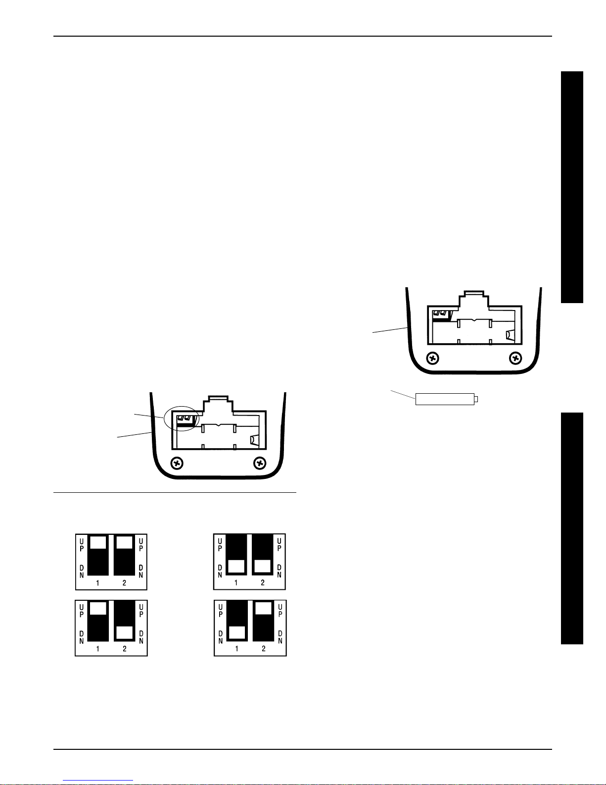
FREQUENCY CHANNEL/BATTERY
CHANGING FREQUENCY CHANNEL
(FIGURE 1)
NOTE: This procedure is for deluxe model beds only.
The frequency of the pendant has been factory set for a specific frequency. The shipping box and the control box underneath the bed will specify the frequency the pendant is set.
If using two (2) twin size as a king size bed, both beds can be
set to the same frequency to operate with one (1) pendant.
1. Raise the head end of the bed to expose the control box.
2. Unplug the bed from the wall outlet.
3. Locate two (2) prong channel switch on the control box.
4. Switch channel to one (1) of the settings in FIGURE 1.
5. Remove the battery cover on the back of the pendant.
FREQUENCY CHANNEL/BATTERY
REPLACING BATTERY (FIGURE 2)
NOTE: This procedure is for deluxe model beds only.
NOTE: Deluxe Model Pendants require one (1) 12V bat-
tery.
1. Remove the battery cover on the back of the pendant.
2. Note existing battery orientation for installation of new
battery.
3. Remove the existing battery from the pendant.
4. Install the new battery into the pendant in the orientation noted in STEP 2.
5. Reinstall the battery cover on the back of the pendant.
F
R
E
Q
U
E
N
C
Y
C
H
A
N
N
E
L
6. Match the channel setting in the pendant with the control
box setting determined in STEP 4.
7. Reinstall the battery cover on the back of the pendant.
8. Plug the bed into the wall outlet.
Two (2) Prong
Channel Switch
Back of
Pendant
CHANNEL SWITCH SETTINGS
A
C
Back of
Pendant
12V Battery
Orientation
FIGURE 2 - REPLACING BATTERY
B
A
T
T
E
R
Y
B
FIGURE 1 - CHANGING FREQUENCY CHANNEL
D
11
Page 12

INV ACARE CORPORATION l ONE INVACARE WAY l Elyria, OH 44035
l Customer Service (800) 333-6900 l Technical Support (800) 832-4707
Form No. 98-317 P/N 1085400 Rev. (1) -2/99 Printed in USA
 Loading...