

Invacare®I-Lift™
ILIFTHM,ILIFTEM,ILIFTEE
ENPortablePatientLift
UserManual...............................3
FCLève-personneportatif
Manuel d'utilisation........................55
ThismanualMUSTbegiventotheuseroftheproduct.
BEFOREusingthisproduct,readthismanualandsaveforfuturereference.

©2012InvacareCorporation.
Allrightsreserved.Republication,duplicationormodificationinwholeorinpartisprohibitedwithout
priorwrittenpermissionfromInvacare.Trademarksareidentifiedby™and®.Alltrademarksare
ownedbyorlicensedtoInvacareCorporationoritssubsidiariesunlessotherwisenoted.

Contents
ThismanualMUSTbegiventotheuseroftheproduct.
BEFOREusingthisproduct,readthismanualandsaveforfuture
reference.
1General......................................5
1.1Symbols..................................5
2Safety........................................6
2.1GeneralGuidelines..........................6
2.2OperatingInformation.......................6
General................................6
PinchPointsandPositioning.................7
ElectricalandGrounding....................7
Disposal................................8
2.3RadioFrequencyInterference..................8
2.4ProductLabeling...........................9
3TechnicalData................................10
3.1PatientLift................................10
3.2FullBodyandHeavyDutySlings................11
3.3DividedLegandToiletingSlings................12
3.4I-LiftScaleILS450...........................12
4Assembly.....................................13
4.1SafeAssembly.............................13
4.2AssemblingtheMasttotheBase................13
4.3AssemblingtheManual/HydraulicPumptothe
Boom...................................15
4.4AssemblingtheElectricActuatortotheBoom......16
4.5InstallingtheLegActuatortotheBase............17
4.6InstallingtheShifterHandle...................17
4.7CheckingtheServiceLight....................18
4.8ResettingtheServiceLight....................18
5Operation....................................19
5.1Introduction..............................19
5.2Closing/OpeningLegs........................19
Closing/OpeningManualLegs................19
Closing/OpeningElectricLegs................20
5.3Raising/LoweringtheLift.....................21
Raising/LoweringaManual/HydraulicLift........21
Raising/LoweringanElectricLift..............22
5.4ActivatingaMechanicalEmergencyRelease........22
PrimaryEmergencyRelease..................22
SecondaryEmergencyRelease................23
5.5PerforminganEmergencyStop.................23
5.6MountingtheBatteryCharger.................24
5.7ChargingtheBattery........................24
6LiftingthePatient..............................26
6.1SafeLifting................................26
6.2PreparingtoLift............................27
6.3AttachingtheSlingstotheLift.................29
6.4LiftingandTransferringthePatient..............31
FloorTransfer...........................32
CommodeTransferGuidelines...............33
BedTransfer............................33
WheelchairTransfer.......................34
7Troubleshooting...............................35
7.1TroubleshootingTable.......................35
8Maintenance..................................37
8.1SafeMaintenance...........................37
8.2MaintenanceSafetyInspectionChecklist..........37
8.3LubricatingtheLift..........................39
8.4DetectingWearandDamage..................39
8.5CleaningtheSlingandLift.....................39
8.6MaintainingtheManual/HydraulicPump...........39

8.7ReplacingaManual/HydraulicPump..............40
8.8AdjustingthePumpControlValve..............41
8.9ReplacingtheElectricActuator.................42
8.10ReplacingtheLegActuator....................43
8.11CheckingandTighteningMastPivotBolt..........44
8.12ReplacingtheSwivelBar......................44
8.13MaintainingtheBaseAdjustment................45
8.14ReplacingRearCasters.......................46
8.15ReplacingFrontCasters......................46
9Scale........................................47
9.1ScaleIntroduction..........................47
9.2RemovingtheSwivelBar.....................47
9.3InstallingtheScale..........................48
9.4OperatingtheScale.........................49
9.5WeighingthePatient........................50
9.6ReplacingtheBattery........................51
9.7CalibratingtheScale.........................51
9.8Troubleshooting...........................52
DisplayCodes...........................52
10Warranty.....................................53
10.1LimitedWarranty—NorthAmerica............53
11Survey.......................................54
11.1UsabilitySurvey............................54
General
1General
1.1Symbols
Signalwordsareusedinthismanualandapplytohazardsorunsafe
practiceswhichcouldresultinpersonalinjuryorpropertydamage.
Seetheinformationbelowfordefinitionsofthesignalwords.
WARNING!
–Warningindicatesapotentiallyhazardoussituation
which,ifnotavoided,couldresultindeathorserious
injury.
CAUTION!
–Cautionindicatesapotentiallyhazardoussituation
which,ifnotavoided,mayresultinpropertydamage
orminorinjuryorboth.
IMPORTANT
–Indicatesahazardoussituationthatcouldresultin
damagetopropertyifitisnotavoided.
Givesusefultips,recommendationsandinformationfor
efficient,trouble-freeuse.
Dateofmanufacture.
1171892-A5

I-Lift™
2Safety
2.1GeneralGuidelines
WARNING!
–DONOTusethisproductoranyavailableoptional
equipmentwithoutfirstcompletelyreadingand
understandingtheseinstructionsandanyadditional
instructionalmaterialsuchasowner’smanuals,service
manualsorinstructionsheetssuppliedwiththis
productoroptionalequipment.Ifyouareunableto
understandthewarnings,cautionsorinstructions,
contactahealthcareprofessional,dealerortechnical
personnelbeforeattemptingtousethisequipmentotherwise,injuryordamagemayoccur.
WARNING!
ACCESSORIESWARNING
–Invacareproductsarespecificallydesignedand
manufacturedforuseinconjunctionwithInvacare
accessories.Accessoriesdesignedbyother
manufacturershavenotbeentestedbyInvacareand
arenotrecommendedforusewithInvacareproducts.
NOTICE
–Theinformationcontainedinthisdocumentissubject
tochangewithoutnotice.
Checkallpartsforshippingdamagebeforeusing.Incaseofdamage,
DONOTusetheequipment.ContacttheDealerforfurther
instructions.
2.2OperatingInformation
Thissectionofthemanualcontainsgeneralsafetyinformation
aboutyourproduct.Forspecificsafetyinformation,refertothe
appropriatesectionofthemanualandprocedureswithinthatsection.
Forinstance,forsafetyinformationrelatedtoassemblingthelift,
referto4.1SafeAssembly,page13.
General
WARNING!
RiskofFalling
TheInvacarepatientliftisNOTatransportdevice.It
isintendedtotransferanindividualfromoneresting
surfacetoanother(suchasabedtoawheelchair).
DONOTattemptanytransferwithoutapprovalof
thepatient’sphysician,nurseormedicalassistant.
ThoroughlyreadtheinstructionsinthisOwner’sManual,
observeatrainedteamofexpertsperformthelifting
proceduresandthenperformtheentireliftprocedure
severaltimeswithpropersupervisionandacapable
individualactingasapatient.
Invacareslingsandpatientliftaccessoriesarespecifically
designedtobeusedinconjunctionwithInvacare
patientlifts.Slingsandaccessoriesdesignedbyother
manufacturersarenottobeutilizedasacomponentof
Invacare’spatientliftsystem.
–Usecommonsenseinalllifts.SpecialcareMUST
BEtakenwithpeoplewithdisabilitieswhocannot
cooperatewhilebeinglifted.
61171892-A
Safety
PinchPointsandPositioning
WARNING!
RiskofInjury
Pinchpointsarepresentinseverallocationsonthelift
andfingerscouldbepinched.
Thehangerbarcanmovesuddenlyandcauseinjury.
–ALWAYSkeephandsandfingersclearofmovingparts
toavoidinjury.
–Whenpositioninglift,beawareofthepositionofthe
hangerbarandthepatient.Injurycouldoccur.
ElectricalandGrounding
WARNING!
GROUNDINGINSTRUCTIONS
DONOT,underanycircumstances,cutorremove
theroundgroundingprongfromanyplugusedwith
orforInvacareproducts.Somedevicesareequipped
withthree-prong(grounding)plugsforprotection
againstpossibleshockhazards.Whereatwo-prong
wallreceptacleisencountered,itisthepersonal
responsibilityandobligationofthecustomertocontact
aqualifiedelectricianandhavethetwo-prongreceptacle
replacedwithaproperlygroundedthree-prongwall
receptacleinaccordancewiththeNationalElectrical
Code.Ifyoumustuseanextensioncord,useONLYa
three-wireextensioncordhavingthesameorhigher
electricalratingasthedevicebeingconnected.In
addition,InvacarehasplacedRED/ORANGEwarning
tagsonsomeequipment.DONOTremovethesetags.
–Carefullyreadbattery/batterychargerinformation
priortoinstalling,servicingoroperatingyourpatient
lift.
–Toreducetheriskofelectricshock,thisproducthas
apolarizedplug(onebladeiswiderthantheother).
Thisplugwillfitinapolarizedoutletonlyoneway.
Iftheplugdoesnotfitfullyintheoutlet,reverse
theplug.Ifitstilldoesnotfit,contactaqualified
electriciantoinstalltheproperoutlet.DONOT
changethepluginanyway.
1171892-A7
I-Lift™
Disposal
WARNING!
EnvironmentalHazard
Thisproducthasbeensuppliedfromanenvironmentally
awaremanufacturerthatcomplieswiththeWaste
ElectricalandElectronicEquipment(WEEE)Directive
2002/96/CE.
Devicecontainsleadacidbatteries.
Thisproductmaycontainsubstancesthatcouldbe
harmfultotheenvironmentifdisposedofinplaces
(landfills)thatarenotappropriateaccordingto
legislation.
–DONOTdisposeofbatteriesinnormalhousehold
waste.TheyMUSTbetakentoaproperdisposalsite.
Contactyourlocalwastemanagementcompanyfor
information.
–Pleasebeenvironmentallyresponsibleandrecyclethis
productthroughyourrecyclingfacilityatitsendoflife.
2.3RadioFrequencyInterference
WARNING!
–MostelectronicequipmentisinfluencedbyRadio
FrequencyInterference(RFI).CAUTIONshould
beexercisedwithregardtotheuseofportable
communicationequipmentintheareaaroundsuch
equipment.IfRFIcauseserraticbehavior,PUSHthe
RedPowerSwitchOFFIMMEDIATELY.DONOT
turnthePowerSwitchONwhiletransmissionisin
progress.
81171892-A
Safety
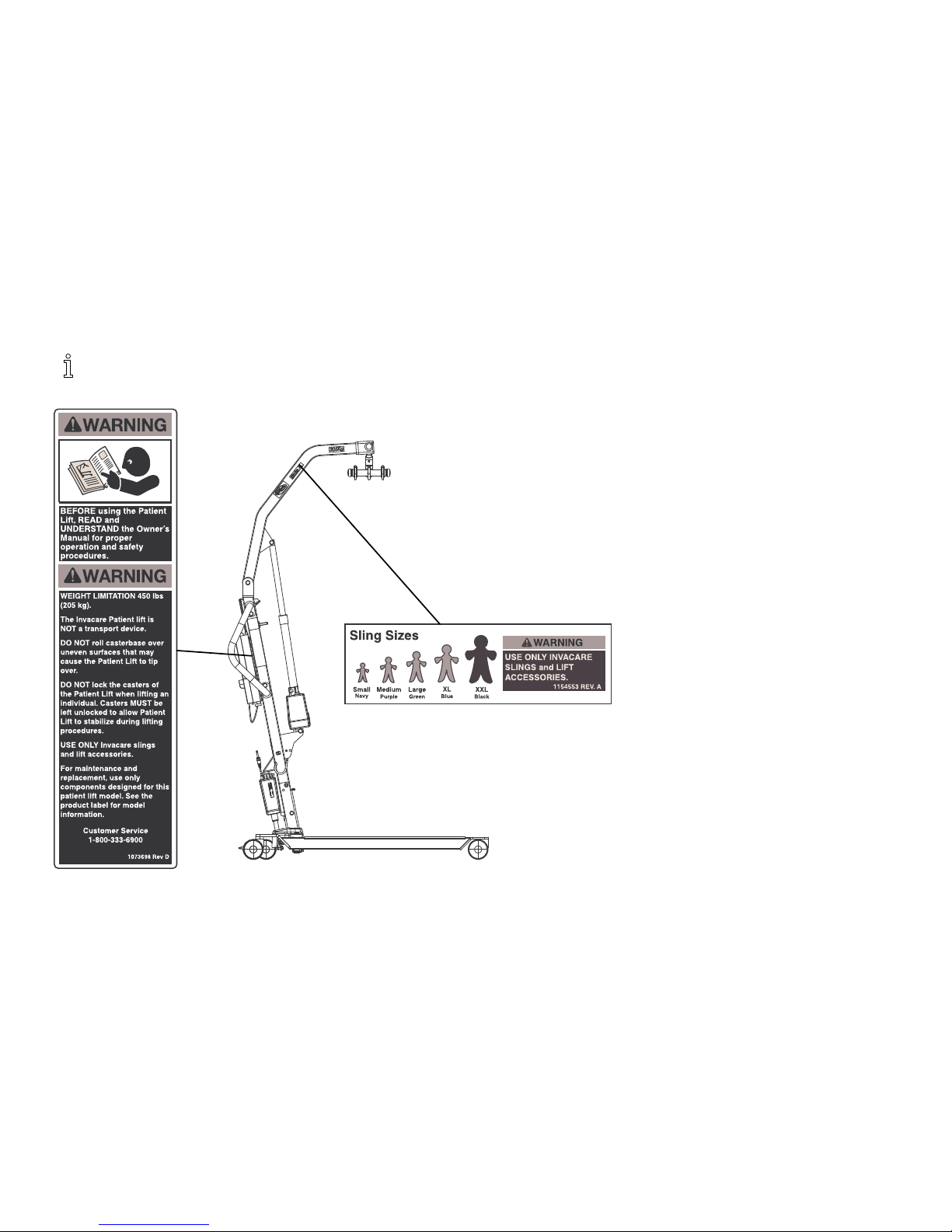
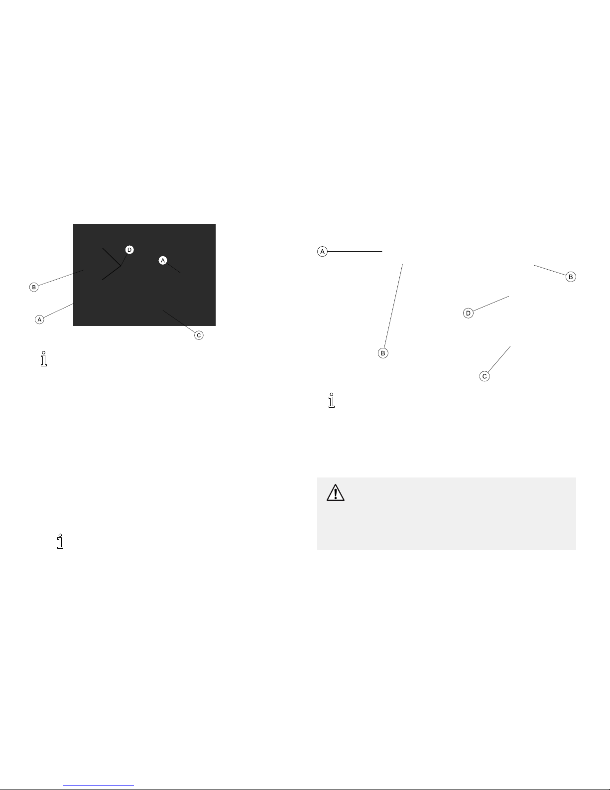
2.4ProductLabeling
Electricliftshown.Locationsarethesameonthehydraulic/manuallift.
1171892-A9

I-Lift™
3TechnicalData
3.1PatientLift
ILIFTHMILIFTEMILIFTEE
HeightatSlingHook-up-MAX.:
71.5in/1816mm76.1in/1933mm
HeightatSlingHook-up-MIN.:
22.8in/579mm22.2in/564mm
BaseWidthOPEN:47in/1196mm53.4in/1358mm
BaseWidthCLOSED:27.8in/705mm
BaseHeight(Clearance):
4.6in/117mm
BaseLength:
46.6in/1184mm
CasterSize:3.94in/100mm
SlingOptions:
3Styles3Styles1Style
TurningDiameter
57in/1450mm
57.6in/1464
MaxLiftingCapacity(WeightCapacity):
450lb/205kg
TotalWeight110lb/49.9kg117.5lb/53.3kg120lb/54.4kg
CyclesfromaFullCharge(Variesdepending
uponloadandstroke):
N/A
Approximately40cycles
Battery:
N/A
24VDC(Rechargeable)
ChargerInput:
N/A100-240VAC
ChargerOutput/ChargingTime:
N/A29.5VDCMax6hrs
Accessories:
DigitalScale
AudioLowBatteryAlarm:
N/A
Yes
MotorSafetyDevices:
N/A
Anti-Entrapment
WarrantyPump/Electronics:
1Year
WarrantyFrame3years
101171892-A

TechnicalData
3.2FullBodyandHeavyDutySlings
FullBody
FullBody
w/Commode
Heavy
Dutyw/o
Commode
Heavy
Dutyw/
Commode
R110
R112*
R111
R113*
R114R115R116R117*R140*R141*
Size:
MLXLMLXL
N/AN/A
Width:41.5
45.545.5
41.5
45.445.54545
Commode
Opening:
N/AN/AN/A889N/A
7
Length:
54.7
60.565.3
54.7
60.565.3
5555
Commode
Opening:
N/AN/AN/A111113N/A13
Back:
N/AN/AN/AN/AN/AN/AN/AN/A
WeightCapacity
(lbs):
450450450450450450600600
*Slingsmadeofameshmaterial.
Alldimensionsareininchesexceptwherenoted.
1171892-A
11

I-Lift™
3.3DividedLegandToiletingSlings
DividedLegToileting
R100PR100R101R102R121
Size:
PMLXLL
Width:3337.541
44.5
36
CommodeOpening:
N/AN/AN/AN/AN/A
Length:
59.862.867.872.337
CommodeOpening:
N/AN/AN/AN/AN/A
Back:
29.235.741.743.2N/A
WeightCapacity(lbs):
450450450450450
Alldimensionsareininchesexceptwherenoted.
3.4I-LiftScaleILS450
WeightRange:Upto600lbs.(272.7Kg)
Resolution:
+/-0.2lbs(.1Kg)
Display:
LiquidCrystalDigital
AutomaticPowerDown:Two(2)minutes
Size:5-3/4LX3-5/8WX4H
Weight:
.55lbs
Power:
Nine(9)VoltAlkalinebattery(included)
BatteryLife:Approximately1500readings
TemperatureRange:
50°To104°F(10°To40°C)
12
1171892-A

Assembly
4Assembly
4.1SafeAssembly
WARNING!
RiskofInjury
Improperassemblymaycauseinjuryordamage.
–UseonlyInvacarepartsintheassemblyofthispatient
lift.Thebaselegs,themast,boom,pumpassembly
andthehangerbararemanufacturedtospecifications
thatassurecorrectalignmentofallpartsforsafe
functionaloperation.
–DONOTovertightenthemountinghardware.This
willdamagethemountingbracket.
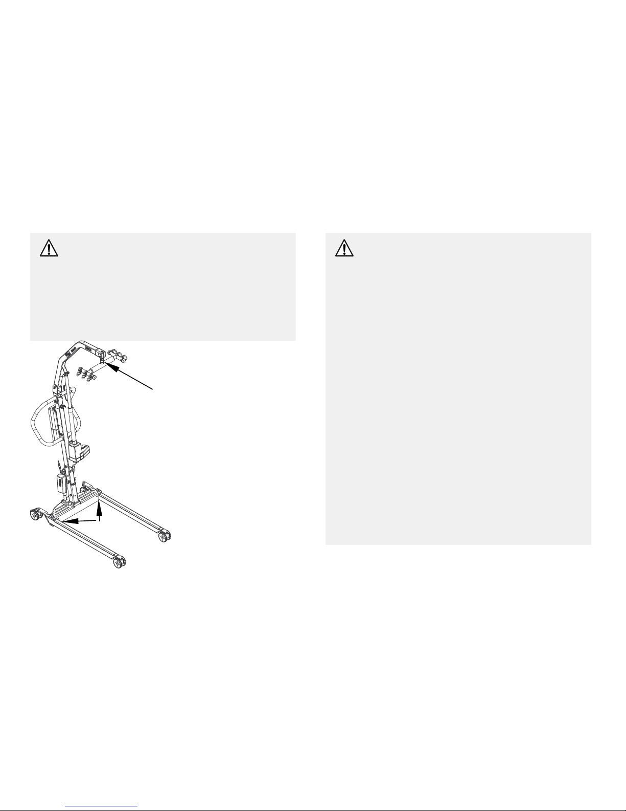
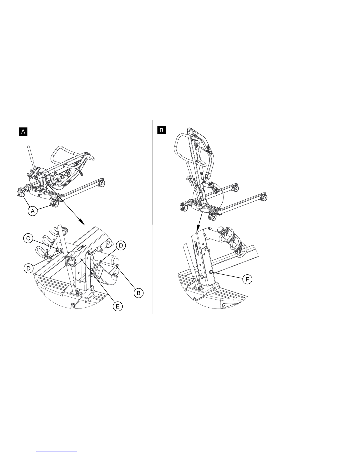
4.2AssemblingtheMasttotheBase
1.LockrearcastersA(DetailA).
2.RemovetheshoulderboltB,nutCandwashersD,fromthe
mastE.
3.Raisethemastassemblytoanuprightpositionuntilitlocksin
place(DetailB).
4.Installtheshoulderboltandwashers,throughthemastandthe
baseF.
5.Securewiththenut.
WARNING!
–Themastmaybefoldedforstorageortransporting.
Eachtimethemastisfolded,themastMUSTbe
properlysecuredtothebaseassembly.
1171892-A13
I-Lift™
14
1171892-A
Assembly
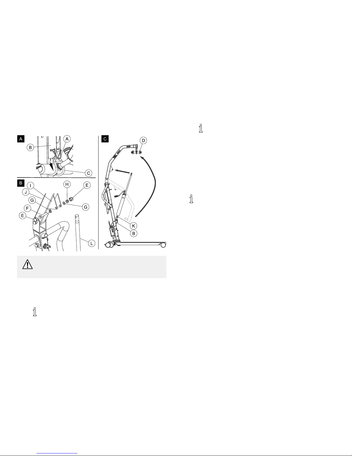
4.3AssemblingtheManual/HydraulicPumpto
theBoom
CAUTION!
–DONOTovertightenthemountinghardware.This
willdamagethemountingbracket.
1.RemovethequickreleasepinAfromthemastmountingbracket
B(DetailA).
2.LiftthehookCsecuringthehangerbarDtothemast.
ThehangerbarisnotshowninthehookinDetailA.
3.RemovethecapsE,boltF,washersGandnutHfromthe
mountingbracketIontheboomJ(DetailB).
ThebottomofthehydraulicpumpassemblyKwill
alreadybeassembledtothemastmountingbracket
(DetailC).
4.Lift-upontheboomandplaceitonyourleftshoulder.
5.Letthehydraulicpumprestontheright-sideofyourchestand
rotatetheshaftextensionLofthehydraulicpumpassembly
untilitlines-upwiththemountingbracketholesontheboom.
6.Aligntheholesofthemountingbracketwiththoseoftheshaft
extension
7.Installthebolt,washers,nutandcaps.
Besurethattheboltiscompletelythroughtheholesof
theboommountingbracketandthemanual/hydraulic
pumpassembly.Theboomassemblywillpivoteasilyifthe
mountinghardwareisalignedproperlywhentheboomis
securedtothemast.
1171892-A15

I-Lift™
4.4AssemblingtheElectricActuatortothe
Boom
CAUTION!
RiskofDamage
–DONOTovertightenthemountinghardware.This
willdamagethemountingbracket.
1.RemovethequickreleasepinAfromthemastmountingbracket
B(DetailA).
2.LiftthehookCsecuringthehangerbarDtothemast.
3.RemovethecapsE,boltF,washersG,bushingHandnutI
fromtheboommountingbracketJ(DetailB).
ThebottomoftheelectricactuatorassemblyKwill
alreadybeassembledtothemastmountingbracket
(DetailC).
4.Lift-upontheboomandplaceitonyourleftshoulder.
5.Lettheactuatorrestonyourright-sideofyourchestandrotate
theshaftextensionLoftheactuatorassemblyuntilitlines-up
withthemountingholesintheboomassembly.
6.Aligntheholesoftheboomassemblymountingbracketwith
thoseoftheactuator
Besurethattheboltiscompletelythroughtheholesof
theboommountingbracketandtheactuatorassembly.
Theboomassemblywillpivoteasilyifthemounting
hardwareisalignedproperlywhentheboomissecured
tothemast.
7.Installthebolt,washers,nut,bushingandcaps.
8.Plugintheelectricalconnectors(notshown)fromtheelectric
actuatortothebottomofthebatteryassembly.
9.Plugthependantcontrolintothebottomofthebatteryassembly
M.Besurethependantcontrolplugisfullyinserted.
161171892-A
Assembly
4.5InstallingtheLegActuatortotheBase
1.Performthefollowingtosecurethelegactuatortothemast
bracket:
a.PositionlegactuatorAintothemastbracketB.
b.MovethelegsCtoaligntheholesinthelegactuatorwith
theholesinthemastbracket.
c.InstallthepinDthroughtheholesofthelegactuatorand
mastbracketandsecurewithhitchpinsE.
2.ConnectthelegactuatorcableFtothebottomofthecontrol
boxG.
3.Ensuretheactuatorplugisfullypushedintothecontrolbox.
4.Checktheservicelight.Referto4.7CheckingtheServiceLight,
page18.
4.6InstallingtheShifterHandle
ThisprocedureappliestotheILIFTHMandILIFTEMonly.
1.RemovetheshifterhandleAfromthepackagingcarton.
2.Line-uptheshifterhandlethreadsBwiththreadedopeningC
inthebase.
3.Turntheshifterhandleclockwiseandsecurelytightenintothe
base.
1171892-A17
I-Lift™
4.7CheckingtheServiceLight
ThisprocedureappliestotheILIFTEEmodelsonly.
Eachtimetheliftisassembled,andbeforeusingthelift,the
servicelightshouldbechecked.
1.Assemblethelift.
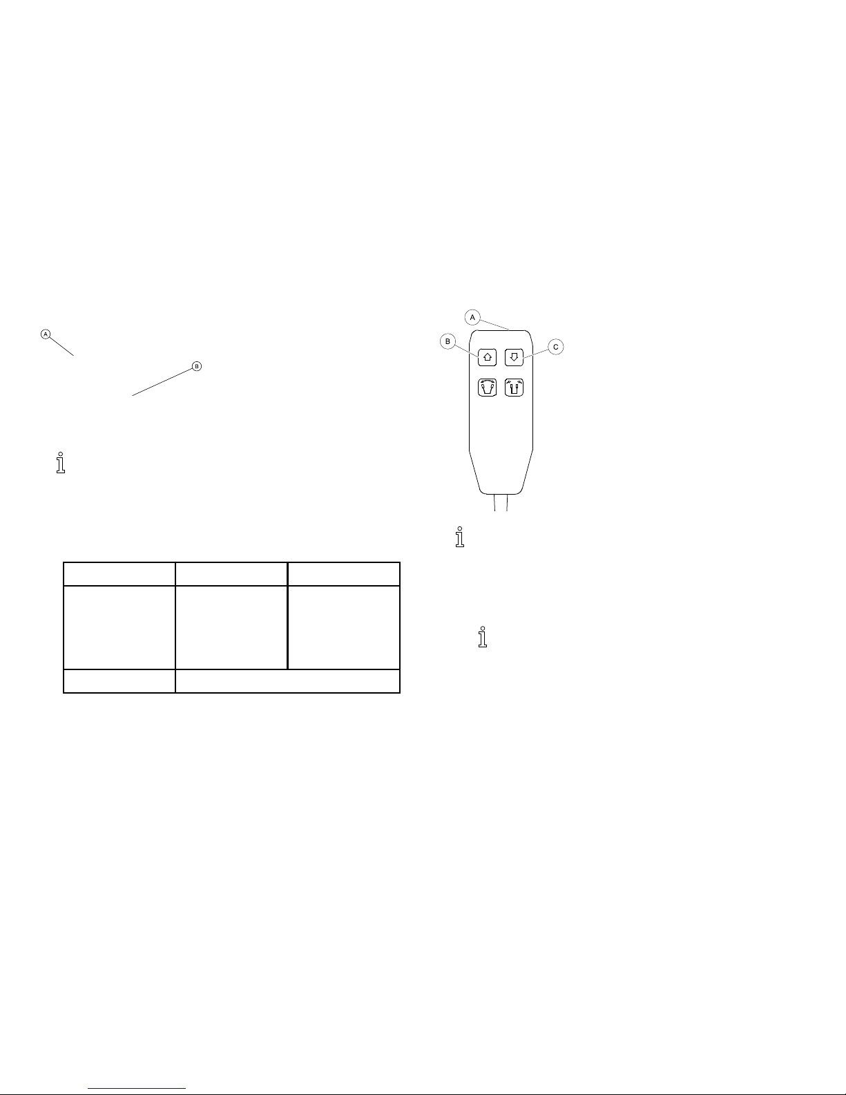
2.ExaminethecontrolboxAtoseeiftheservicelightBisflashing.
3.Refertothetable.
ServiceLight
InitialAssembly
Reassembly
FlashingResettheservice
light.Referto
4.8Resettingthe
ServiceLight,page
18.
Theliftrequires
service.Contact
yourlocalInvacare
dealerforservice.
NotFlashing
Theliftisreadyforuse.
4.8ResettingtheServiceLight
Thisprocedureshouldonlybeperformedafterperforming
4.7CheckingtheServiceLight,page18.
1.LocatethehandsetA.
2.PressandholdtheUPbuttonBandDOWNbuttonCatthe
sametimeforfiveseconds.
Youwillhearasoundwhentheservicelighthasbeen
reset.
181171892-A

Operation
5Operation
5.1Introduction
Theoperationofthepatientliftisaneasyandsafeprocedure.
Beforeusingtheliftwithapatient,refertothefollowing
proceduresforsafetyinformationandinstruction:
•2.2OperatingInformation,page6
•6.4LiftingandTransferringthePatient,page31
5.2Closing/OpeningLegs
WARNING!
RiskofInjury
Theliftcouldtipandendangerthepatientandassistants.
–Thelegsoftheliftmustbeinthemaximumopen
positionforoptimumstabilityandsafety.Ifitis
necessarytoclosethelegsofthelifttomaneuverthe
liftunderabed,closethelegsoftheliftonlyaslongas
ittakestopositiontheliftoverthepatientandliftthe
patientoffthesurfaceofthebed.Whenthelegsof
theliftarenolongerunderthebed,returnthelegsof
thelifttothemaximumopenposition.
–Theshifterhandlemustbelockedinplaceforoptimum
stabilityandsafety.
Closing/OpeningManualLegs
Theshifterhandleisusedtoopenorclosethelegsofthebasefor
stabilitywhenliftingapatient.
Refertothesafetyinformationin5.2Closing/OpeningLegs,
page19beforeperformingthisprocedure.
1.Standattherearofthepatientliftandgrasptheshifterhandle
withonehandandplacetheoppositehandonthesteering
handleofthemastforbalance.
TheshifterhandleMUSTlockintoitsmountingslottolock
thelegsinthefullclosedposition.
1171892-A19
I-Lift™
WARNING!
RiskofInjury
Theliftcouldtipandendangerthepatientandassistants.
–IftheshifterhandleisNOTpositionedcompletelyinto
itsmountingslot,DONOTusethepatientliftuntil
theshifterhandleisproperlyseatedandthelegsof
thepatientliftarelockedinplace.
2.Performoneofthefollowing:
a.ClosingtheLegsA—Pulltheshifterhandleawayfromthe
patientliftandthentoyourleftuntilitlocksinthenotchof
thebracket.
b.OpeningtheLegsB—Pulltheshifterhandleawayfrom
thepatientliftandthentoyourright.
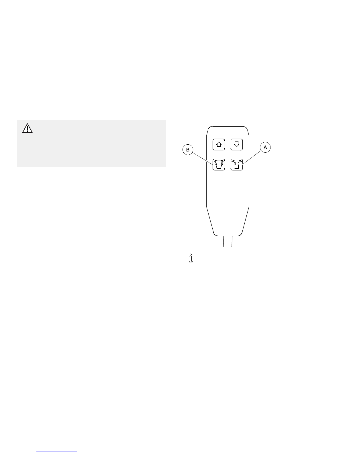
Closing/OpeningElectricLegs
Thependantisusedtoopenorclosethelegsofthebaseforstability
whenliftingapatient.
Refertothesafetyinformationin5.2Closing/OpeningLegs,
page19beforeperformingthisprocedure.
1.Toclosethelegs,pressthelegsclosedbuttonA.
2.Toopenthelegs,pressthelegsopenbuttonB.
201171892-A
Operation
5.3Raising/LoweringtheLift
WARNING!
RiskofInjury
Theliftcouldtipandendangerthepatientandassistants.
–Invacaredoesnotrecommendlockingoftherear
castersofthepatientliftwhenliftinganindividual.
–Invacaredoesrecommendthattherearcastersbeleft
unlockedduringliftingprocedurestoallowthepatient
lifttostabilizeitselfwhenthepatientisinitiallylifted
fromachair,bedoranystationaryobject.
Raising/LoweringaManual/HydraulicLift
Refertothesafetyinformationin5.3Raising/Loweringthe
Lift,page21beforeperformingthisprocedure.
Therearetwocontrolsonthepumpassembly:
•Thecontrolvalve
•Thepumphandle
1.Toraisethelift:
a.PositionthecontrolvalveintheclosedpositionA(towards
thepumphandleC).
b.MovethepumphandleupanddowntoelevatetheboomD
untilitlocksinthenotchofthebracket.
c.Ensuretheboomhaslockedinthenotchofthebracket.
2.Tolowerthelift:
a.GentlyopenBthecontrolvalve(awayfromthepump
handle).
b.IfthereisnopatientintheslingE,pulldownontheboom.
Therateofdescentoftheboomiscontrolledbythe
amountthatthecontrolvalveisopen.
Asafetygateispartofthehydraulicsystemthatcontrols
themaximumdescentoftheboomregardlessofhowfar
thecontrolvalveisopened.
1171892-A
21
I-Lift™
Raising/LoweringanElectricLift
Refertothesafetyinformationin5.3Raising/Loweringthe
Lift,page21beforeperformingthisprocedure.
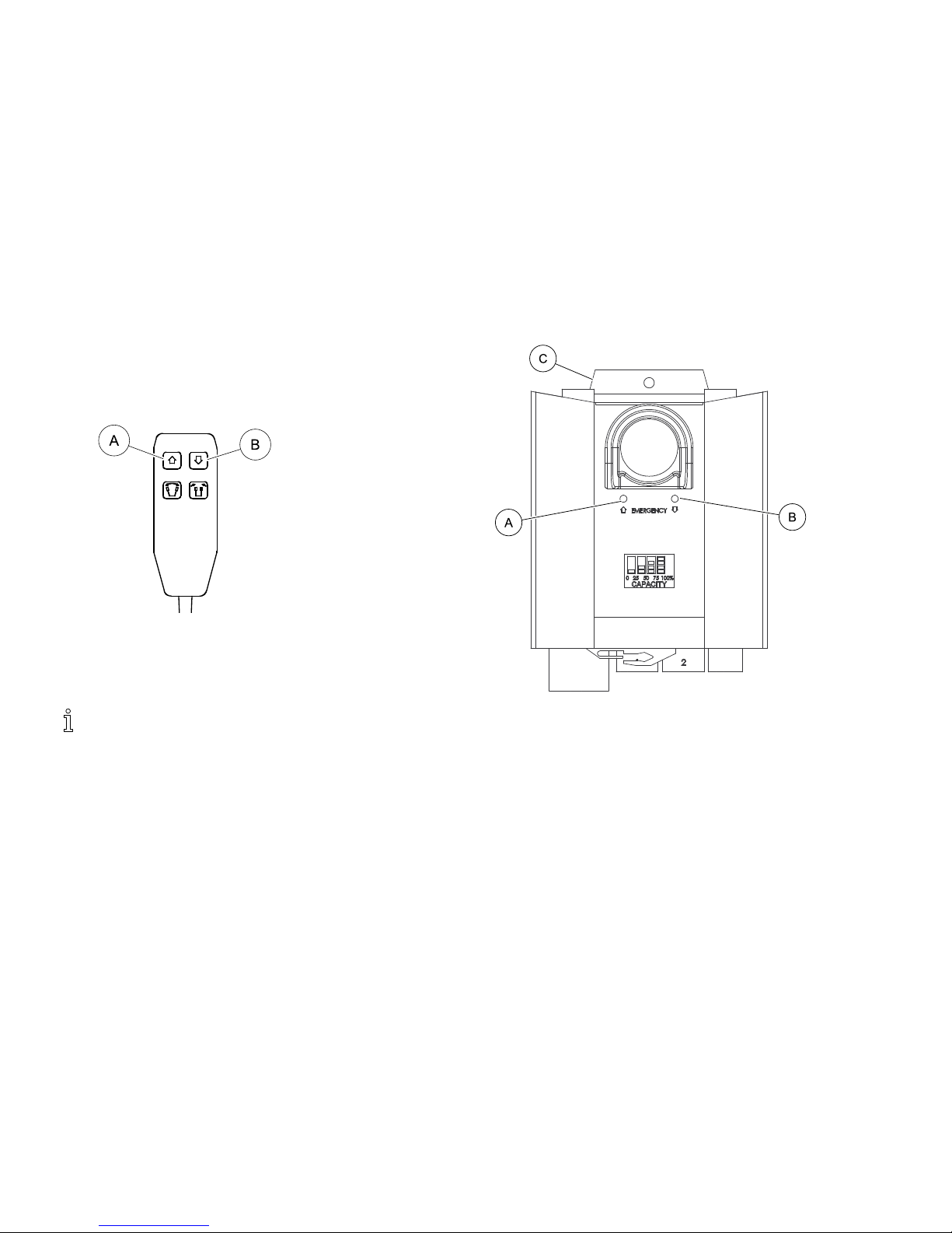
1.Toraisethelift—PresstheUPAbuttontoraisetheboom
andthepatient.
2.Tolowerthelift—PresstheDOWNBbuttontolowerthe
boomandthepatient.
5.4ActivatingaMechanicalEmergencyRelease
Therearetwotypesofmechanicalemergencyrelease—primary
andsecondary.
PrimaryEmergencyRelease
1.InsertapenintotheholelabeledEmergencyUpAorEmergency
DownBonthecontrolboxC.
22
1171892-A

Operation
SecondaryEmergencyRelease
Itisrecommendedthattheprimaryemergencyreleasebe
used.Thesecondaryemergencyreleaseisonlyaback-upto
theprimaryemergencyrelease.
Incaseswheretheprimaryreleaseiseithernotfunctioningor
unreachable,asecondaryemergencyreleasemaybeused.
1.PullupontheEMERGENCYgripAandpushdownonthe
boomBatthesametime.
5.5PerforminganEmergencyStop
1.PresstheREDbuttonAonthecontrolboxBintostopthe
boomandpatientfromraisingorlowering.
2.Toreset,rotatetheemergencybuttonclockwise.
1171892-A23
I-Lift™
5.6MountingtheBatteryCharger
Refertoyourlocalregulationsconcerningpropermounting
procedures.
1.PlacethebatterychargerwithmountingbracketAonthewall
atthedesiredposition.
2.Withapencil,markthemiddleholeBposition.
3.Measuredown6½inchesfromthepencilmarkanddrillone
mountinghole.
4.InstallthebottommountingscrewCuntilthereisan
approximate1/8-inchgapbetweenthescrewheadandthewall.
5.Installthebatterychargerwithmountingbracketontothe
bottommountingscrew.
6.Drilltheremainingtwomountingholes.
7.InstallthetworemainingmountingscrewsDthroughthe
mountingbracketandintothewall.Tightensecurely.
8.Plugthebatterychargerintothewallelectricaloutlet.
ONLEDshouldilluminate.
5.7ChargingtheBattery
Invacarerecommendsthebatteryberechargeddailyto
prolongbatterylife.
Anaudiblealarmwillsound(hornwillbeep)whenbattery
islow.
1.LiftuponthehandleAonthebackofthebatteryB.
2.LiftthebatteryupandoutawayfromthecontrolboxC.
CAUTION!
Mountingthebatteryimproperlymaycauseinjuryor
damage.
–Makesurethereisanaudibleclickwhenmounting
batteryonthebatterychargertoconfirmproper
mounting.
3.PlacethebatteryonthebatterychargerDasshown.Makesure
thereisanaudibleclick.
24
1171892-A

Operation
ThechargeLEDwillilluminate.Whenchargingis
complete,chargeLEDwillstopilluminating.
Abatteryneedingtobefullyrechargedwilltake
approximatelyfourhours.
4.Liftuponthehandleonthebackofthebattery.
5.Liftthebatteryupandoutawayfromthebatterycharger.
CAUTION!
Mountingthebatteryimproperlymaycauseinjuryor
damage.
–Makesurethereisanaudibleclickwhenmounting
batteryonthecontrolboxtoconfirmproper
mounting.
6.Reinstallthebatteryontothecontrolboxasshown.Makesure
thereisanaudibleclick.
Thebatterymountstothecontrolboxandbatterycharger
asshown.
1171892-A25

I-Lift™
6LiftingthePatient
6.1SafeLifting
WARNING!
RiskofInjury
Theliftcouldtipandendangerthepatientandassistants.
–Refertothesafetyinformationandinstructionsin
thefollowingproceduresBEFOREperformingthis
procedure:
6.2PreparingtoLift,page27
6.3AttachingtheSlingstotheLift,page29
6.4LiftingandTransferringthePatient,page31
–AlthoughInvacarerecommendsthattwoassistantsbe
usedforallliftingpreparation,transferringfromand
transferringtoprocedures,ourequipmentwillpermit
properoperationbyoneassistant.Theuseofone
assistantisbasedontheevaluationofthehealthcare
professionalforeachindividualcase.
–DONOTexceedmaximumweightlimitationofthe
patientlift.TheweightlimitationfortheI-Liftis450
lbs(205kg).
–DONOTattemptanytransferwithoutapprovalof
thepatient’sphysician,nurseormedicalassistant.
ThoroughlyreadtheinstructionsinthisOwner’s
Manual,observeatrainedteamofexpertsperform
theliftingproceduresandthenperformtheentirelift
procedureseveraltimeswithpropersupervisionand
acapableindividualactingasapatient.
WARNING!
Riskofinjury
Theliftcouldtipandendangerthepatientandassistants.
–Duringtransfer,withpatientsuspendedinasling
attachedtothelift,DONOTrollcasterbaseover
unevensurfacesthatcouldcausethepatientliftto
tipover.
–Usesteeringhandleonthemastatalltimestopushor
pullthepatientlift.
–WheelchairwheellocksMUSTbeinalockedposition
beforeloweringthepatientintothewheelchairfor
transport.
–Beforetransferring,checkthatthewheelchairweight
capacitycanwithstandthepatient'sweight.
261171892-A
LiftingthePatient
6.2PreparingtoLift
RefertotheSafetysectioninthismanualandreviewthe
informationin6.1SafeLifting,page26beforeproceeding
furtherandobserveallwarningsindicated.
Beforepositioningthelegsofthepatientliftunderabed,
makesurethattheareaisclearofanyobstructions.
WARNING!
RiskofInjury
Theliftcouldtipandendangerthepatientandassistants.
–Thelegsoftheliftmustbeinthemaximumopen
positionforoptimumstabilityandsafety.Ifitis
necessarytoclosethelegsofthelifttomaneuverthe
liftunderabed,closethelegsoftheliftonlyaslongas
ittakestopositiontheliftoverthepatientandliftthe
patientoffthesurfaceofthebed.Whenthelegsof
theliftarenolongerunderthebed,returnthelegsof
thelifttothemaximumopenposition.
–Theshifterhandlemustbelockedinplaceforoptimum
stabilityandsafety.
1.Positionthepatientontothesling.Refertoyourslingowner’s
manual.
2.Unlocktherearcasters.
3.Openandlockthelegs.Referto5.2Closing/OpeningLegs,page
19.
1171892-A27
I-Lift™
4.Usethesteeringhandletopushthepatientliftintoposition.
5.Lowerthepatientliftforeasyattachmentofthesling.
6.Locktherearcasters.
7.Proceedto6.4LiftingandTransferringthePatient,page31.
281171892-A

LiftingthePatient
6.3AttachingtheSlingstotheLift
WARNING!
RiskofFalling
Improperlyinstalledslingsordamagedslingscancause
thepatienttofallorcauseinjurytoassistants.
–UseanInvacareapprovedslingthatisrecommended
bytheindividual’sdoctor,nurseormedicalassistant
forthecomfortandsafetyoftheindividualbeinglifted.
–Aftereachlaundering(inaccordancewithinstructions
onthesling),inspectsling(s)forwear,tears,andloose
stitching.
–Bleached,torn,cut,frayed,orbrokenslingsareunsafe
andcouldresultininjury.Discardimmediately.
–DONOTalterslings.
–Besuretochecktheslingattachmentseachtimethe
slingisremovedandreplaced,toensurethatitis
properlyattachedbeforethepatientisremovedfrom
astationaryobject(bed,chairorcommode).
WARNING!
–Ifthepatientisinawheelchair,securethewheellocks
inplacetopreventthechairfrommovingforwards
orbackwards.
–DONOTremovethestrapretainersfromthehanger
barhooks.Thestrapretainersmustbeclosedwhen
thestrapsareproperlyinstalledonthehooks.
–Whenconnectingslingsequippedwithcolorcoded
strapstothepatientlift,theshortestofthestraps
MUSTbeatthebackofpatientforsupport.Using
longsectionwillleavelittleornosupportforpatient's
back.Theloopsoftheslingarecolorcodedand
canbeusedtoplacepatientinvariouspositions.
Thecolorsmakeiteasytoconnectbothsidesofthe
slingequally.Makesurethatthereissufficienthead
supportwhenliftingapatient.
Theslingshavecolorcodedstrapstoassistwithproper
attachment.
1171892-A29

I-Lift™
1.PlacethestrapsAoftheslingBoverhooksCofthehanger
barD.
ThestrapretainerFcloseswhentheslingstrapis
properlyseatedonthehookG.
2.Matchthecorrespondingcolorsoneachsideoftheslingforan
evenliftofthepatient.
ModelNos.R110-R117FullBodySlingsandModel
Nos.R120-R122ToiletingSlingshavefourslingstraps
(twoperside—SeeDetailA).ModelNos.R100-R102
DividedLegSlingshavesixslingstraps(threeperside
—SeeDetailB).
InvacareLiftSwivelBarshavethreehookuppointsper
side.ThemiddlehookupEisONLYusedforslingsthat
havethreesetsofstrapsperside.
3.Usethelift.Referto6.4LiftingandTransferringthePatient,
page31.
301171892-A

LiftingthePatient
6.4LiftingandTransferringthePatient
WARNING!
RiskofInjury
Theliftcouldtipandendangerthepatientandassistants.
–Refertothesafetyinformationandinstructionsin
thefollowingproceduresBEFOREperformingthis
procedure:
6.1SafeLifting,page26
6.2PreparingtoLift,page27
6.3AttachingtheSlingstotheLift,page29
5.3Raising/LoweringtheLift,page21
–Invacaredoesnotrecommendlockingoftherear
castersofthepatientliftwhenliftinganindividual.
–Invacarerecommendslockingtherearhangercasters
ONLYwhenpositioningorremovingtheslingfrom
aroundthepatient.
–Invacaredoesrecommendthattherearcastersbeleft
unlockedduringliftingprocedurestoallowthepatient
lifttostabilizeitselfwhenthepatientisinitiallylifted
fromachair,bedoranystationaryobject.
1.Movethelifttothepatientareaandpreparetolift.Referto
6.2PreparingtoLift,page27.
2.Attachtheslingtothelift.Referto6.3AttachingtheSlingsto
theLift,page29.
3.Liftthepatienthighenoughtoclearthestationaryobject
withtheirweightfullysupportedbythelift.Referto5.3
Raising/LoweringtheLift,page21.
Onmanual/hydrauliclift,theboomwillstayinposition
untilthecontrolvalveisopened.Ontheelectriclift,the
boomwillstayinpositionuntiltheDOWN(
)button
ispressed.
1171892-A31

I-Lift™
WARNING!
RiskofInjury
Animproperlyattachedslingcouldcausethepatientto
fall.
Animproperlyadjustedslingcouldcauseinjurytothe
patient.
–Adjustmentsforsafetyandcomfortshouldbemade
beforemovingthepatient.
–Patient'sarmsshouldbeinsideofthestraps.
4.Beforemovingthepatient,checkagaintomakesurethatthe
slingisproperlyconnectedtothehooksofthehangerbar.Ifany
attachmentsarenotproperlyinplace,lowerthepatientback
ontothestationaryobjectandcorrectthisproblem.
5.Usingthesteeringhandle,movetheliftawayfromthestationary
object.
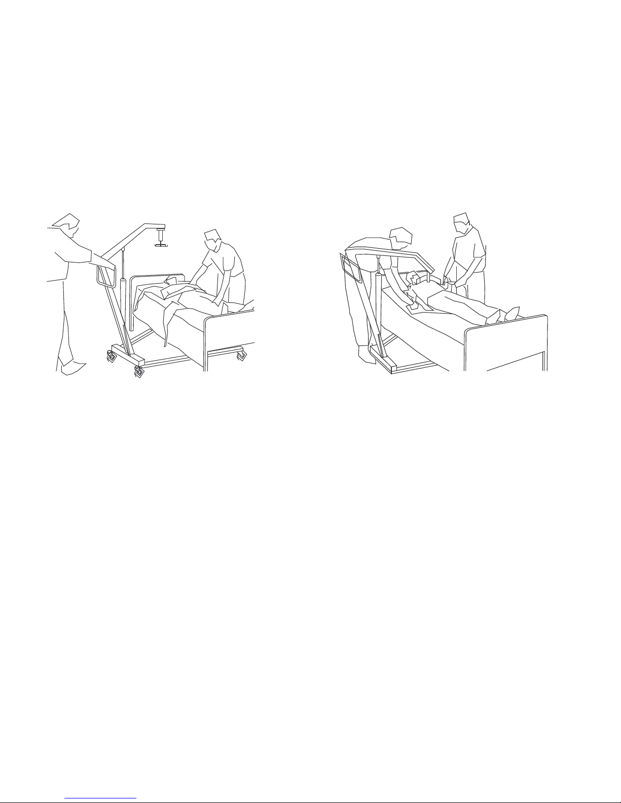
6.Usingthehandlesonthesling,turnthepatientsothathe/she
facestheassistantoperatingthepatientlift(Detail“C”).
7.Lowerthepatientsothathisfeetrestonthebaseofthelift,
straddlingthemast.
Thelowercenterofgravityprovidesstabilitymakingthe
patientfeelmoresecureandthelifteasiertomove.
8.Movethepatientliftwithbothhandsfirmlyonthesteering
handle.
Readandunderstandtheinformationthatpertainsto
transfertoorfromspecifictypesofsurfacesBEFORE
performingthisprocedure:
•BedTransfer,page33
•FloorTransfer,page32
•WheelchairTransfer,page34
•CommodeTransferGuidelines,page33
9.Raiseorlowerthelifttopositionthepatientoverthestationary
surface.
Besuretoraiseorlowerthepatientenoughtoclearthe
sidesofthestationaryobject.
10.Lowerthepatientontothestationarysurface.
11.Locktherearcasters.
12.Detachtheslingfromthehangerbar.
Theslingcanbeleftunderthepatient,ifdesired.
13.Unlocktherearcasters.
14.Movetheliftawayfromthearea.
FloorTransfer
Performthesestepsinadditiontothosein6.4LiftingandTransferring
thePatient,page31whentransferringfromthefloor:
1.Determineifthepatienthassufferedanyinjuriesfromafall.If
nomedicalattentionisneeded,proceedwiththetransfer.
2.Positiontheslingunderthepatient.
RefertothePatientSlingsowner’smanual,partnumber
1023891,formoreinformationaboutpositioningslings.
3.Oneassistantshouldhavethepatientbendhiskneesandraise
hisheadoffofthefloor.
Thisassistantshouldsupportthepatient’sheadwitha
pillow.
4.Theotherassistantshouldopenthelegsofthelift.
5.Positiontheliftwithonelegunderthepatient’sheadandthe
otherlegunderthepatient’sbentknees.
Keeptheslingstrapsinsideofthelegsofthelift.
321171892-A

LiftingthePatient
6.Lowertheboomsothehangerbarisdirectlyoverthepatient’s
chest.
7.Attachtheslingandproceedwiththetransfer.Referto6.4
LiftingandTransferringthePatient,page31.
Ensurethepatient’sarmsareinsideofthesling.
CommodeTransferGuidelines
Performthesestepsinadditiontothosein6.4LiftingandTransferring
thePatient,page31whentransferringtoorfromacommode.
Theslingswithcommodeopeningsaredesignedtobeused
witheitheracommodechairorstandardcommode.
1.Beforetransferringthepatient,thepatientliftshouldbe
guidedtothebathroomfacilitiestocheckthatitcanbeeasily
maneuveredtowardsthecommode.
TheInvacarepatientliftisNOTintendedasatransport
device.IfthebathroomfacilitiesareNOTnearthebed
orifthepatientliftcannotbeeasilymaneuveredtowards
thecommode,thenthepatientMUSTbetransferredto
awheelchairandtransportedtothebathroomfacilities
beforeusingthepatientliftagaintopositionthepatient
onastandardcommode.
2.Attachtheslingstothelift.Referto6.3AttachingtheSlingsto
theLift,page29.
3.Elevatethepatienthighenoughtoclearthecommodechairarms
andhavetheirweightsupportedbythepatientlift.Referto5.3
Raising/LoweringtheLift,page21
4.Bothassistantsshouldhelpguidethepatientontothecommode.
5.Lowerthepatientontothecommode,leavingtheslingattached
tothehangerbarhooks.
Invacarerecommendsthattheslingremainconnectedto
thehangerbarhooksduringthepatient’suseofeither
thecommodechairorstandardcommode.
6.Whencomplete,recheckforcorrectslingattachment.
7.Raisethepatientoffofthecommode.
8.Whenthepatientisclearofthecommodesurface,usethe
steeringhandlestomovetheliftawayfromthecommode.
9.Performoneofthefollowing:
•Returnthepatienttothebed.Reversetheproceduresin:
–6.4LiftingandTransferringthePatient,page31
–5.3Raising/LoweringtheLift,page21
–6.3AttachingtheSlingstotheLift,page29
•Returnthepatienttoawheelchair.RefertoWheelchair
Transfer,page34.
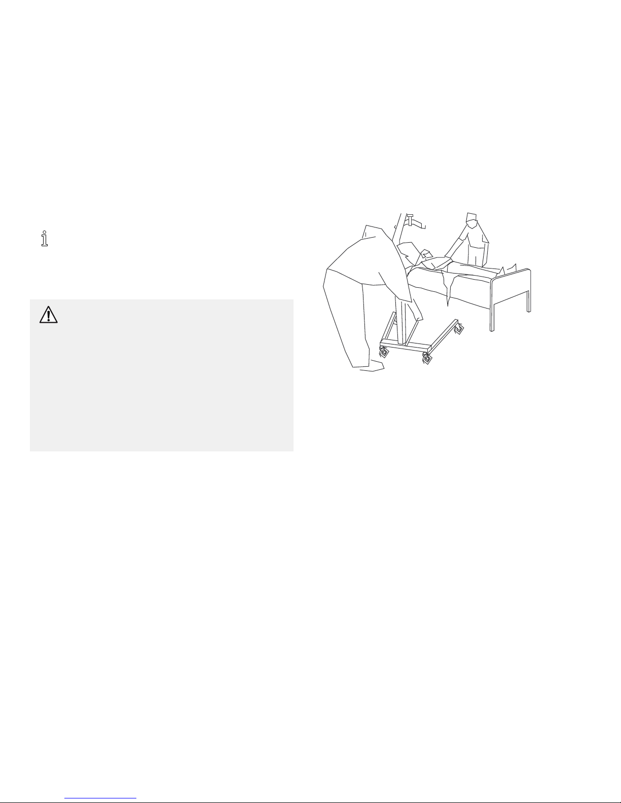
BedTransfer
Usethefollowingguidelineswhentransferringtoorfromabed:
•Positionthepatientasfaroverthebedaspossible.
•Ifpatientisbeingtransferredfromasurfacethatislowerthan
thebed,presstheuparrowbuttontoraisethepatientabove
thesurfaceofthebed.Thepatientshouldbeelevatedjusthigh
enoughtoclearthebedwiththeirweightfullysupportedby
thelift.
•Whenthepatientisclearofthebedsurface,swingtheirfeet
offthebed(Detail“B”).
•Aftertransfer,unhooktheslingfromallattachmentpointson
theliftandremovetheslingfromaroundthepatient.
1171892-A33

I-Lift™
WheelchairTransfer
WARNING!
RiskofInjury
–Beforetransferring,checkthatthewheelchairweight
capacitycanwithstandthepatient’sweight.
–ThewheelchairwheellocksMUSTbeinalocked
positionbeforeloweringthepatientintothe
wheelchairfortransport.
Performthesestepsinadditiontothosein6.4LiftingandTransferring
thePatient,page31whentransferringtoorfromawheelchair:
1.Engagethewheellocksofthewheelchairtopreventmovement
ofthewheelchair.
2.Positionthepatientovertheseatwiththeirbackagainstthe
backofthechair.
3.Begintolowerthepatienteitherbyopeningthecontrolvalve
orbypressingtheDOWN(ê)button.
4.Withoneassistantbehindthechairandtheotheroperatingthe
patientlift,theassistantbehindthechairwillpullbackonthe
grabhandle(onselectmodels)orsidesoftheslingtoseatthe
patientwellintothebackofthechair.Thiswillmaintainagood
centerofbalanceandpreventthechairfromtippingforward.
Usethestrapsorhandlesonthesideandthebackof
theslingtoguidethepatient’shipsasfarbackaspossible
intotheseatforproperpositioning.
5.Leavetheslinginplace.
Removeonlyifadividedlegslingwasused.
341171892-A

Troubleshooting
7Troubleshooting
7.1TroubleshootingTable
SYMPTOMSFAULTSSOLUTION
Mast/Basejointloose.Referto4.2AssemblingtheMasttotheBase,
page13.
Patientliftfeelsloose.
Tie-Rodsareloose.
Referto8.13MaintainingtheBaseAdjustment,
page45.
Casters/Brakesnoisyorstiff.Fluffordebrisinbearings.Referto8.15ReplacingFrontCasters,page46
and8.14ReplacingRearCasters,page46.
Noisyordrysoundfrompivots.
Needslubrication.
Referto8.3LubricatingtheLift,page39.
Oilleakingfromhydraulics.Hydraulicpumpinneedofreplacement.Referto8.7ReplacingaManual/Hydraulic
Pump,page40.ContactyourDealer.
ControlValvenotfullyclosed.CloseControlValve.
Referto8.7ReplacingaManual/Hydraulic
Pump,page40.ContactyourDealer.
Manual/Hydraulicpumpinneedof
replacement.
Checkconnections.
Manual/Hydraulicpumpfailstoliftwhen
pumped.
Controlvalvemaybeoutofadjustment.Referto8.8AdjustingthePumpControl
Valve,page41.
1171892-A35

I-Lift™
SYMPTOMSFAULTSSOLUTION
Hand-controloractuatorconnectorloose.
Connecthandcontroloractuatorconnector.
Ensureconnectorsareseatedproperlyand
fullyconnected.
Batterylow.
Chargebatteries.Referto5.7Chargingthe
Battery,page24.
REDemergencystopbuttonpressedIN.RotateREDemergencystopbutton
CLOCKWISEuntilitpopsout.
Batterynotconnectedproperlytocontrol
box.
Reconnectthebatterytothecontrolbox.
Referto5.7ChargingtheBattery,page24.
Theconnectingterminalsaredamaged.
Replacethebatterypack.Referto5.7
ChargingtheBattery,page24.
Electricactuatorfailstoliftorlegsfailtoopen
whenbuttonispressed.
Boomorlegactuatorinneedofserviceor
loadistoohigh.
Referto8.9ReplacingtheElectricActuator,
page42.or8.10ReplacingtheLegActuator,
page43.ContactyourDealer.
Unusualnoisefromactuator.Actuatoriswornordamagedorspindleis
bent.
Referto8.7ReplacingaManual/Hydraulic
Pump,page40,8.9ReplacingtheElectric
Actuator,page42or8.10ReplacingtheLeg
Actuator,page43.ContactyourDealer.
Boomwillnotlowerinuppermostposition.Boomrequiresaminimumweightloadto
lowerfromtheuppermostposition.
Pulldownslightlyontheboom.
Boomwillnotlowerduringapower
retraction.
Shoulderboltatthejunctionoftheboomand
mastmaynotbeproperlyinstalled.
Referto8.11CheckingandTighteningMast
PivotBolt,page44.
Hydraulicpumpdriftswhenunderload.Controlvalvemaybeoutofadjustment.Referto8.8AdjustingthePumpControl
Valve,page41.
Ifproblemsarenotremediedbythesuggestedmeans,pleasecontactyourdealerorInvacare.
361171892-A

Maintenance
8Maintenance
8.1SafeMaintenance
WARNING!
RiskofFalling
MaintenanceMUSTbeperformedonlybyqualifiedpersonnel.
Improperassemblymaycauseinjuryordamage.
–Regularmaintenanceofpatientliftsandaccessoriesisnecessarytoassureproperoperation.
–Thepumpissealedatthefactory.DONOTattempttoopenthepumporobtainlocalserviceasthiswillVOIDthewarrantyand
mightresultindamage.ConsultyourdealerorwriteInvacareforfurtherinformation.
–DONOTovertightenthemountinghardware.Thiswilldamagethemountingbracket.
8.2MaintenanceSafetyInspectionChecklist
Regularcleaningwillreveallooseorwornparts,enhancesmoothoperationandextendthelifeexpectancyofthelift.
Followthemaintenanceproceduresdescribedinthismanualtokeepyourpatientliftincontinuousservice.
TheInvacarePatientLiftisdesignedtoprovideamaximumofsafe,efficientandsatisfactoryservicewithminimumcareandmaintenance.
AllpartsoftheInvacareLiftaremadeofthebestgradesofsteel,butmetaltometalcontactwillwearafterconsiderableuse.
Thereisnoadjustmentormaintenanceofeitherthecastersorbrakes,otherthancleaning,lubricationandcheckingaxleandswivelboltsfor
tightness.Removealldebris,etc.fromthewheelandswivelbearings.Ifanypartsareworn,replacethesepartsimmediately.
Ifyouquestionthesafetyofanypartofthelift,contactyourDealerimmediatelyandadvisehim/herofyourproblem.
Theitemsinthefollowingchecklistshouldbecheckedinitiallyandinthefollowingintervals:
•INSTITUTIONALUSE—Monthlyandpriortoeachnewuser
•IN-HOMEUSE—EverySixMonths
1171892-A37

I-Lift™
DateofInspection:
Initials:
THECASTERBASE
qInspectformissinghardware.
qBaseopens/closeswithease.
qInspectcastersandaxleboltsfortightness.
qInspectcastersforsmoothswivelandroll.
qInspectandclearwheelsofdebris.
qInspectpivotjointsforwear.
THEMAST
qMastMUSTbesecurelyassembledto
boom.
qInspectforbendsordeflections.
qInspectpivotjointsforwear.
THEHANGERBAR
qCheckthebolt/hooksforwearordamage.
qCheckslinghooksforwearordeflection.
qInspectpivotjointsforwear.
qCheckthatstrapretainersareinplaceand
functioning.
SLINGSANDHARDWARE
qCHECKALLSLINGATTACHMENTS
eachtimeitisusedtoensureproper
connectionandpatientsafety.
qInspectslingmaterialforwear.
qInspectstrapsforwear.
THEBOOM
qCheckallhardwareandhangerbar
supports.
qInspectforbendsordeflections.
qInspectboltedjointsofboomforwear.
qInspecttoensurethattheboomis
centeredbetweenthebaselegs.
qCheckthemastpivotbolt.Ensurethat
theboltistightlysecured.
qInspectpivotjointsforwear.
THEMANUAL/HYDRAULIC
PUMP/ELECTRICACTUATOR
ASSEMBLY
qCheckforleakage.
qInspecthardwareonmast,boomandbase.
qCheckforwearordeterioration.IF
DAMAGED,RETURNTOFACTORY.
qCycletoensuresmoothquietoperation
oftheelectricactuator.
qCheckforsmoothoperationofthepump
handle.
THESHIFTERHANDLE
qOperatessmoothly.
qLocksadjustablebasewheneverengaged.
THECONTROLVALVE
qOpensandcloseseasily.
CLEANING
qWhenevernecessary.
381171892-A

Maintenance
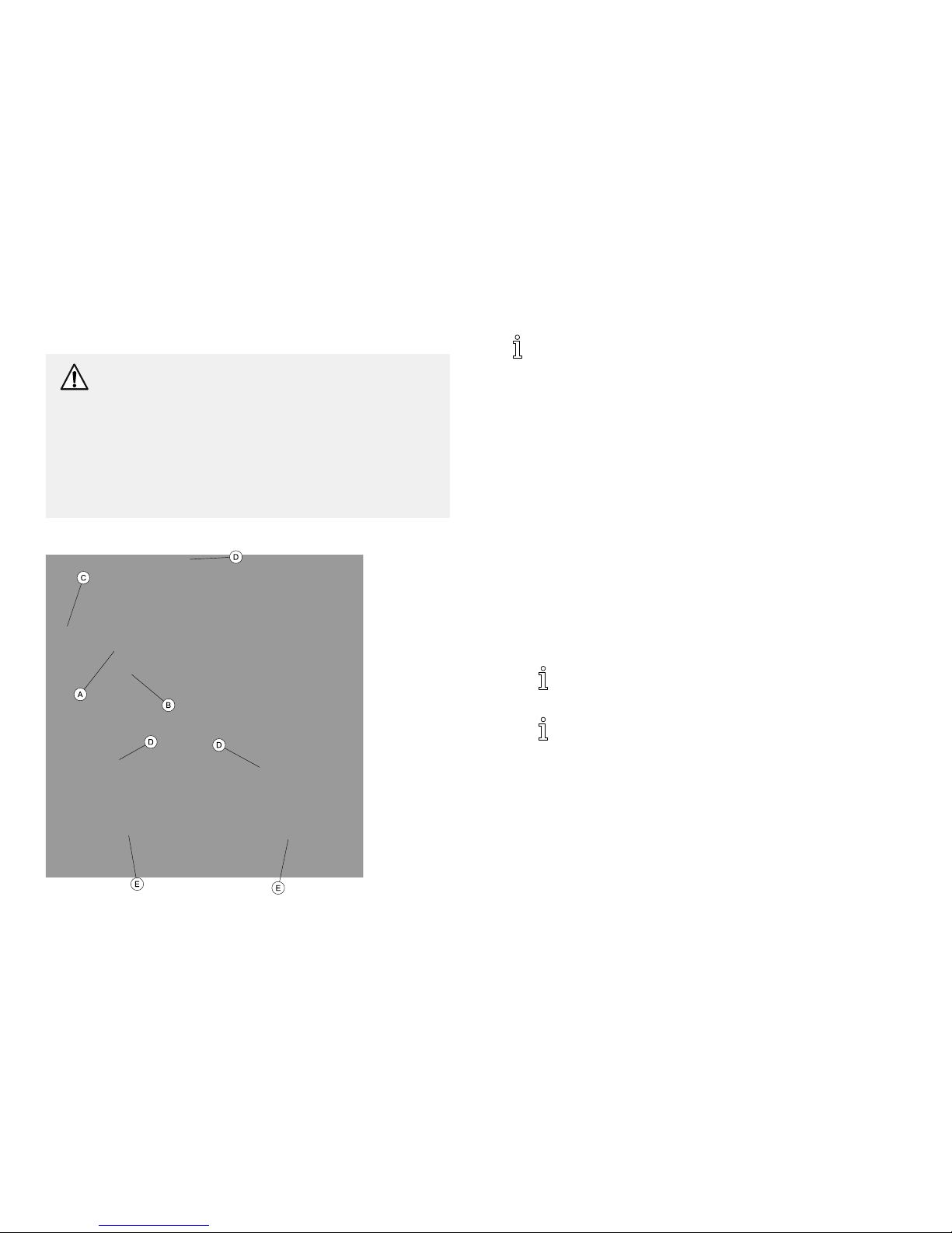
8.3LubricatingtheLift
TheInvacareliftisdesignedforminimummaintenance.However,
asixmonthcheckandlubricationshouldensurecontinuedsafety
andreliability.
Keepliftandslingscleanandingoodworkingorder.Anydefect
shouldbenotedandreportedtoyourDealerassoonaspossible.
Refertothefigureforlubricationpoints.Lubricateallpivotpoints
withalightgrease(waterproofautolubricant).Wipeallexcess
lubricantfromliftsurface.
1.SwivelBar
2.BoomMountingBracket
3.Boom/MastMount
4.MastMountingBracket
8.4DetectingWearandDamage
Itisimportanttoinspectallstressedparts,suchasslings,hangerbar
andanypivotforslingsforsignsofcracking,fraying,deformationor
deterioration.Replaceanydefectivepartsimmediatelyandensure
thattheliftisnotuseduntilrepairsaremade.
8.5CleaningtheSlingandLift
Theslingshouldberegularlywashedinwater,temperaturenotto
exceed180°F(82°C),andabiocidal(anti-biological)solution.Asoft
cloth,dampenedwithwaterandasmallamountofmilddetergent,
isallthatisneededtocleanthepatientlift.Theliftcanbecleaned
withnon-abrasivecleaners.
8.6MaintainingtheManual/HydraulicPump
AllpartsoftheManual/HydraulicPumpareprecisionmachined,then
carefullyassembledandtestedtoensurereliableservice.Thepump
assemblyiscompletelyenclosedandsealedwithneopreneringsto
preventleakageofhydraulicoil.Asmallamountofoil(aboutadrop)
willaccumulatearoundthepistonfromtimetotimeandshouldbe
removedwithafacialtissue.
WARNING!
–Thepumpissealedatthefactory.DONOTattempt
toopenthepumporobtainlocalserviceasthiswill
voidthewarrantyandmightresultindamageand
costlyrepair.ConsultyourdealerorwriteInvacare
forfurtherinformation.
1171892-A39

I-Lift™
8.7ReplacingaManual/HydraulicPump
CAUTION!
RiskofDamage
Improperassemblymaycauseinjuryordamage.
–DONOTovertightenthemountinghardware.This
willdamagethemountingbracket.
1.LoosenthenutAthatsecurestheballofthepumpBintothe
mountingsocketC.
2.ResttheboomDonyourshoulderandremovethenutF,bolt
G,nylonwasherEandwashersHfromtheboommounting
bracketI.
3.Removethepump.
4.Reversestepsforinstallation.
401171892-A

Maintenance
8.8AdjustingthePumpControlValve
WARNING!
–Alwaysremovethepatientfromtheliftbefore
performingthisprocedure.DONOTperformthis
adjustmentwhileliftingapatient.Seriousinjurymay
occur.
ThisprocedureappliestotheILIFTHMmodelsonly.
1.TurnthecontrolvalveAsoitwillclearthepumphandleB
whenthehandleisfullyretracted.
2.LoosenthesetscrewCafewturns.
3.Removethecontrolvalvelever.
4.HandtightenthecontrolrodDbyturningitclockwise.
5.Reinstallthecontrolvalvelever.
6.Positiontheleversoitclearsthehandlewhenitisfullyretracted.
7.Tightenthesetscrew.
8.Testthehydraulicpumpwithaload.
1171892-A
41

I-Lift™
8.9ReplacingtheElectricActuator 1.RemovethecapsA,nutB,washersC,bushingDandshoulder
boltEthatsecuretheactuatorFtotheboommounting
bracketG.
2.ResttheboomHonyourshoulderandremovethecapsI,nut
J,boltK,washersLandbushingMfromthemastmounting
bracketN.
3.Removetheelectricactuator.
4.ReverseSTEPS1-3forinstallation.
CAUTION!
RiskofDamage
Improperassemblymaycauseinjuryordamage.
–DONOTovertightenthemountinghardware.This
willdamagethemountingbracket.
Besurethattheboltorpiniscompletelythroughthe
holesoftheboomassemblymountingbracketandthe
actuatorassembly.Theboomassemblywillpivoteasilyif
themountinghardwareisalignedproperlywhentheboom
assemblyissecuredtothemast.
42
1171892-A

Maintenance
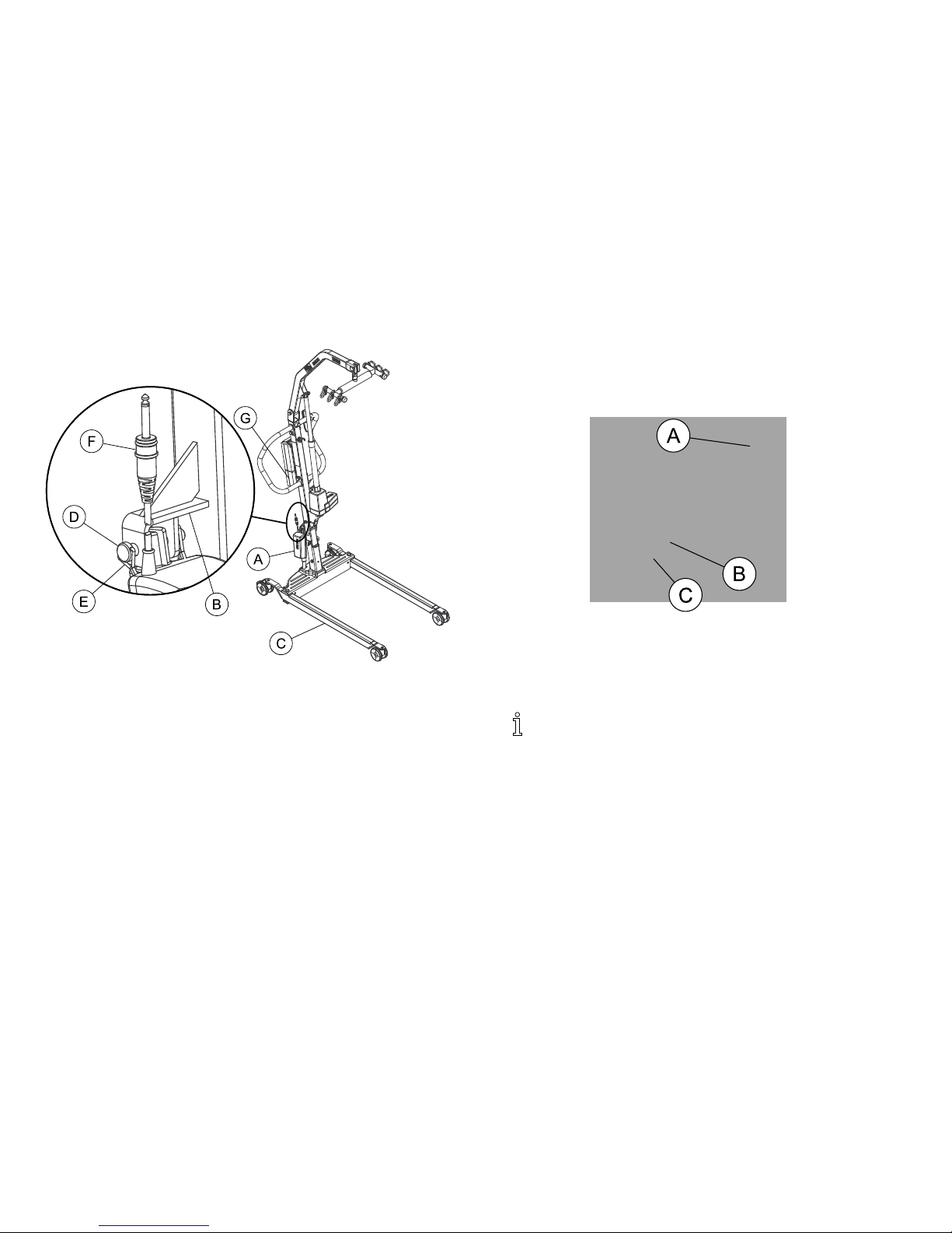
8.10ReplacingtheLegActuator 1.RemovethewirelockAthatsecuresthelegactuatorcable
tothemast.
2.DisconnectthelegactuatorcableBfromthebottomofthe
controlboxC.
3.RemovehitchpinsDsecuringthepinEtothelegactuator
FandmastbracketG.
4.Removethepinfromthelegactuatorandmastbracket.
5.Performthefollowingtoremovethelegactuatorfromthepivot
bracketH(DetailA):
WARNING!
RiskofInjury
Injurytopersonnelordamagetothepatientlift
mayoccur.
–Ensurethatthereissufficientroomtoturnthe
patientliftonitssideandthatthefloorareais
clearofdebris.
a.Turnthepatientliftonitsside.
b.RemovethehitchpinIsecuringthepinJtothepivot
bracket.
c.Removethepinfromthelegactuatorandpivotbracket.
d.Returnthepatientlifttotheuprightposition.
6.SlidethelegactuatoroutoftheslotKinthebaseofthepatient
lift(DetailB).
7.ReverseSTEPS1-5toinstallthelegactuator.
Positionlegactuatorintothemastbracketandmovethe
legstoaligntheholesinthelegactuatorwiththeholesin
themastbracket.
1171892-A43

I-Lift™
8.11CheckingandTighteningMastPivotBolt
1.CheckthattheboltAisthroughthebracketBandthelocknut
Cistightandsecure.
2.Ifneeded,dooneormoreofthefollowing:
•Tightenlocknutandback-offthelocknut1/8ofaturn.
•Replacethelocknut.
8.12ReplacingtheSwivelBar
WARNING!
RiskofInjury
Wornordamagedpartsoftheliftmaycauseinjuryto
thepatientorassistants.
–Afterthefirstyearofuse,thehooksofthehanger
barandmountingbracketsoftheboomshouldbe
inspectedeverysixmonthstodeterminetheextent
ofwear.Ifthesepartsbecomeworn,replacement
mustbemade.
Ifthescaleisinstalledonthelift,referto9.3Installingthe
Scale,page48toreplacethehangerbar.
1.RemovetherubbercoverAfromtheboomB.
2.RemovetheclipCandclevispinDsecuringthehangerbar
pinEtotheboom.
3.ReverseSTEPS1-2toinstallthenewhangerbar.
44
1171892-A

Maintenance
8.13MaintainingtheBaseAdjustment
ThebaseAadjustmentshouldnotrequireanyattentionotherthan
adjustingthelinkagerods.
CAUTION!
Damagetotheliftmayoccur.
–Thelegactuatormustbeinthefullyclosedposition
beforeadjustingthelinkagerods.
1.Closethelegsalltheway.RefertoClosing/OpeningManual
Legs,page19orClosing/OpeningElectricLegs,page20.
2.CheckthesquarenessofthelegsBwhenintheclosedposition.
3.PlaceasquareContheinsideofthelegsandbasetodetermine
the90°alignmentD.
4.AdjustthelinkagerodsEuntil90°alignmentisachieved.
CAUTION!
Damagetotheliftmayoccur.
–DONOTadjustthelinkagerodssothelegsareatless
than90°alignment.
1171892-A45

I-Lift™
8.14ReplacingRearCasters
1.Placetheliftonitsside.
2.RemovetheboltAandlocknutBthatsecuretheexistingrear
casterCandbearingDtotherearcasterbracketE.
3.Installtheboltthroughtherearcasterbracket,bearingandnew
rearcasterandtightensecurelywiththelocknut.
8.15ReplacingFrontCasters
1.Placetheliftonitsside.
2.RemovetheboltA,bearingCandlocknutBthatsecurethe
existingfrontcasterassemblyDtothefrontcasterbracketE.
3.Installtheboltthroughthefrontcasterbracketandthenew
frontcasterassemblyandtightensecurelywiththelocknut.
461171892-A

Scale
9Scale
9.1ScaleIntroduction
TheI-LiftScaleisacompactprecisionscalesystemdesigned
specificallyfortheInvacarePatientLiftSystem.
WARNING!
DONOTinstallorusethisequipmentwithoutfirst
readingandunderstandingtheseinstructions.Ifyou
areunabletounderstandtheWarnings,Cautionsor
Instructions,contactahealthcareprofessional,dealer
ortechnicalpersonnelbeforeattemptingtoinstallthis
equipment-otherwise,injuryordamagemayoccur.
–PatientandslingMUSTberemovedfromtheliftduring
ALLinstallationprocedures.
9.2RemovingtheSwivelBar
1.RemovetherubbercoverAfromtheboomB.
2.RemovetheclipCandclevispinDsecuringthehangerbar
pinEtotheboom.
SavetheclipandclevispintosecuretheI-LiftScaleto
theboom.
1171892-A47

I-Lift™
9.3InstallingtheScale
1.Removethehangerbar.Referto9.2RemovingtheSwivelBar,
page47.
2.PositiontheloadcellassemblyAofthescaleintotheboom
mountingbracketB.
3.Securethescaletotheboommountingbracketwiththeclevis
pinC,twospacersDandtheclipE.
4.SecurethehangerbarFtothescalewiththeshoulderbolt
GandlocknutH.
5.Weighthepatient.Referto9.5WeighingthePatient,page50.
481171892-A

Scale
9.4OperatingtheScale
KeypadFunctions
Key
IndicatorDisplayed
IndicatorLocationDefinition
ON
OFF
OFFCenterofDisplayWindow
Pressingthiskeywillapplypower
tothescaleandturntheuniton.
Whenthescaleisalreadyon,
pressingthebuttonwillturnthe
unitoff.
ZEROZEROLowerLeftCorneroftheDisplay
Window
Pressingthiskeywhenthescaleis
onwillresettheweightshownin
thedisplaywindowtozero.
UNITS
lborkg
UpperRightCorneroftheDisplay
Window
Thefunctionofthiskeyistochange
theunitofmeasurementfrom
pounds(lb)tokilograms(kg).
LOCKUNLOCKLOCKLowerRightCorneroftheDisplay
Window
Thiskeyisusedtolockorunlocka
weightvalueinthedisplaywindow.
NOTE:Weightdisplayedisa
STOREDweightandnotthe
currentweightwhenthekeyisused
inthelockposition.
N/ALOBATCenterofDisplayWindow
Indicatorisshowninthedisplay
windowtonotifywhenbatteryis
low.
1171892-A49

I-Lift™
9.5WeighingthePatient
WARNING!
–Theweightcapacityislimitedtothelowestrated
capacityofanyoneofthecomponentsinuse(e.g.
PatientLift,SlingorScale).Thepatient'sweight
MUSTnotexceedthelowestratedcapacityofany
component.
1.Attachslingstrapstothehangerbar.Forproperattachment
instructionsreferto6.3AttachingtheSlingstotheLift,page29.
ForimprovedaccuracyontheI-Lift,attachallsling
strapstothecenterhooksonbothsidesofthehanger
bar.However,patientcomfortmayrequireadifferent
configurationofslingstraps.
2.PresstheON/OFFkey.
Thedisplaywillindicatethelastweightthatwas
measured.Theword“LOCK”willbeseeninthedisplay
box.
TheZEROkeyispressedinordertoavoidcapturing
theweightoftheslingandthehardware.IftheZERO
keyisnotpressedtheweightoftheslingandtheweight
ofthehardwarewillbeincludedintheweightdisplayed.
Notzeroingoutwillgiveafalsereadingofthepatient’s
trueweight.
3.PresstheZEROkey.WhentheZEROkeyispushedthe
followingwillhappen:
a.Thescalewillresettozeroandtheword“ZERO”will
appearinthedisplay.
b.Thelockfunctionwillthenbeturnedoffandtheword
“LOCK”willdisappearfromthedisplay.
Thescaleisnowactiveandcontinuallyupdatingthe
weightdisplay.
4.Placethepatientinthesling.
5.Attachtheslingtothelift.Referto6.3AttachingtheSlingsto
theLift,page29.
6.Activatetheliftmechanismtoraisethepatientuntiltheyare
completelysupportedbythelift.Forpatientliftinginstructions,
referto6.4LiftingandTransferringthePatient,page31.
7.Notetheweightdisplay.
8.WhentheweightdisplaybecomesstablepresstheLOCKbutton
tolocktheweightdisplay.Thiswillbeindicatedbytheword
“LOCK”appearinginthedisplaywindow.
Shoulditbenecessarytounlocktheweightwhilethe
patientisstillsupportedbythelift,theUNLOCKbutton
maybepressed.Theweightwillunlockandtheword
“LOCK”willdisappearfromthedisplaywindow.The
weightvaluewillthenbeupdated.Oncetheweight
becomesstabletheweightcanbelockedagainby
pressingtheLOCKbutton.
Stablebeingdefinedastheweightfluctuatingtwotenths
ofapound.Forexample,apatientweighingonehundred
pounds,thescalewillfluctuatebetween99.8and100.2
untiltheLOCKkeyispressed.Fluctuationoftheweight
displayedisnormalasnotedabove.PresstheLOCK
buttontolocktheweight.
9.Theliftmaynowbeloweredandtheslingremovedfromthe
patient.
501171892-A

Scale
Thepatient'sweightwillcontinuetobeseeninthe
displaywindow.Thedisplaywillturnoffautomatically
afteratwominuteperiodofnon-use[nochangesin
weightexceedingfivepounds(twokilograms)].Youcan
NOTadjustthetimedelayforautomaticshutoff.After
thedisplayhasturnedoff,theweightmayberecalledby
pressingtheON/OFFbutton.Theunitcanbeturnedoff
bypressingtheON/OFFbuttonasecondtime.
9.6ReplacingtheBattery
Thescaleispoweredbyaninevoltalkalinebatterythat
shouldprovideapproximately1500readingsbeforeneeding
replacement.
Whenbatteryreplacementisneeded,lobatwillappearonthe
display.Performthefollowing:
1.SlidethebatterydoorAopeninthedirectionofthearrowB.
2.Removeexistingbattery.
3.Installthenewbattery.
4.Reinstallthebatterydoor.
9.7CalibratingtheScale
TheI-LiftScalewillbepre-calibratedatthefactorywiththe
loadcell.Shoulditbenecessarytore-calibratethescale,
followtheinstructionsoutlinedbelow.
1.Thepatientandtheslingmustberemovedfromthescaleto
properlycalibratetheI-LiftScale.Forremovingthepatient
instructionsreferto6.4LiftingandTransferringthePatient,page
31.
2.WiththeI-LiftScaleon,removethefourscrewsAontheback
oftheenclosureandremovethefrontcoverBtoexposethe
PCboardC.
1171892-A51

I-Lift™
3.PresstheCALbuttonlocatedonthePCboard.TheCALswitch
isnotlabeledbutistheonlybuttononthePCboardlocatedin
thelowerrightcorner.OncetheCALbuttonispushed“CAL1”
willbeseeninthedisplaywindow.
CAL1selectsthecalibrationmodeusing50poundsof
calibratedweight.CAL2selectsthecalibrationmodefor
usewith200poundsofcalibratedweight.Pressingthe
UNITSkeytogglesbetweenCAL1andCAL2.
4.Whenthedesiredcalibrationmodeisdisplayed,pressthe
LOCK/UNLOCKkey.
ThedisplaywindowwillnowshowUnLd.
5.EnsurethatthereisnoloadonthescaleandpresstheZEROkey.
6.Thedisplaywindowwillshowadashedline(------)scrolling
acrossandthentheword“LOAD”willappearinthedisplay
window.
7.Performoneofthefollowing:
a.FORCAL1OPTION-support50poundsofcalibrated
weightfromthescaleandpresstheZEROkey.
b.FORCAL2OPTION-support200poundsofcalibrated
weightfromthescaleandpresstheZEROkey.
8.Thedisplaywindowwillshowadashedline(------)scrolling
acrossandthentheword“DONE”willappearinthedisplay
window.
9.Removetheweightfromthescaleandpressthe
LOCK/UNLOCKkey.
Theunitwillnowbeinatemporarytestmodeandwill
notlocktheweightdisplay.Thiswillallowweighttobe
loadedandunloadedtocheckthecalibration.
10.TurntheunitoffbypressingtheON/OFFkey.
11.TurntheunitonbypressingtheON/OFFkey.
Scalewillnowbeinnormaloperation.
9.8Troubleshooting
SYMPTOM
PROBABLE
CAUSESOLUTIONS
UnitdoesNOT
workproperly.
Batteryfailure.Checkbattery.
Replaceifnecessary.
Batteryhasbeen
replacedandunit
stilldoesNOT
workproperly.
ContactInvacare
forServiceat
1-800-333-6900
DisplayCodes
CALIBRATIONREQUIRED
-Indicatesimproperstored
calibrationdata,calibrationis
necessary.
OVERCAPACITY-Indicatesa
weightexceedingthecapacity
hasbeenloadedonthescale.
521171892-A

Warranty
10Warranty
10.1LimitedWarranty—NorthAmerica
PLEASENOTE:THEWARRANTYBELOWHAS
BEENDRAFTEDTOCOMPLYWITHFEDERALLAW
APPLICABLETOPRODUCTSMANUFACTUREDAFTER
JULY4,1975.
Thiswarrantyisextendedonlytotheoriginalpurchaser/userofour
products.
Thiswarrantygivesyouspecificlegalrightsandyoumayalsohaveother
legalrightswhichvaryfromstatetostate.
Invacarewarrantstheproductsmanufacturedtobefreefromdefectsin
materialsandworkmanshipforaperiodofthreeyearsontheliftand
oneyearontheslings,hydraulicpump/electriccomponentsfromthe
dateofpurchase.Ifwithinsuchwarrantyperiodanysuchproductshall
beproventobedefective,suchproductshallberepairedorreplaced,at
Invacare’soption.Thiswarrantydoesnotincludeanylabororshipping
chargesincurredinreplacementpartinstallationorrepairofanysuch
product.Invacare’ssoleobligationandyourexclusiveremedyunderthis
warrantyshallbelimitedtosuchrepairand/orreplacement.
Forwarrantyservice,pleasecontactthedealerfromwhomyou
purchasedyourInvacareproduct.Intheeventyoudonotreceive
satisfactorywarrantyservice,pleasewritedirectlytoInvacareatthe
addressonthebackcover,providedealer’sname,address,dateof
purchase,indicatenatureofthedefect.
InvacareCorporationwillissueaserializedreturnauthorization.The
defectiveunitorpartsMUSTbereturnedforwarrantyinspectionusing
theserialnumber,whenapplicableasidentificationwithin30daysof
returnauthorizationdate.Donotreturnproductstoourfactorywithout
ourpriorconsent.C.O.D.shipmentswillberefused;pleaseprepay
shippingcharges.
LIMITATIONSANDEXCLUSIONS:THEFOREGOINGWARRANTY
SHALLNOTAPPLYTOSERIALNUMBEREDPRODUCTSIFTHE
SERIALNUMBERHASBEENREMOVEDORDEFACED,PRODUCTS
SUBJECTEDTONEGLIGENCE,ACCIDENT,IMPROPEROPERATION,
MAINTENANCEORSTORAGE,PRODUCTSMODIFIEDWITHOUT
INVACARE’SEXPRESSWRITTENCONSENT(INCLUDING,BUT
NOTLIMITEDTO,MODIFICATIONTHROUGHTHEUSEOF
UNAUTHORIZEDPARTSORATTACHMENTS;PRODUCTS
DAMAGEDBYREASONOFREPAIRSMADETOANYCOMPONENT
WITHOUTTHESPECIFICCONSENTOFINVACARE,ORTOA
PRODUCTDAMAGEDBYCIRCUMSTANCESBEYONDINVACARE’S
CONTROL,ANDSUCHEVALUATIONWILLBESOLELY
DETERMINEDBYINVACARE.THEWARRANTYSHALLNOTAPPLY
TOPROBLEMSARISINGFROMNORMALWEARORFAILURETO
ADHERETOTHEINSTRUCTIONSINTHISMANUAL.
THEFOREGOINGWARRANTYISEXCLUSIVEANDINLIEUOFANY
OTHEREXPRESSWARRANTIES.IMPLIEDWARRANTIES,IFANY,
INCLUDINGTHEIMPLIEDWARRANTIESOFMERCHANTABILITY
ANDFITNESSFORAPARTICULARPURPOSE,SHALLNOTEXTEND
BEYONDTHEDURATIONOFTHEEXPRESSEDWARRANTY
PROVIDEDHEREINANDTHEREMEDYFORVIOLATIONSOF
ANYIMPLIEDWARRANTYSHALLBELIMITEDTOREPAIROR
REPLACEMENTOFTHEDEFECTIVEPRODUCTPURSUANTTO
THETERMSCONTAINEDHEREIN.INVACARESHALLNOTBE
LIABLEFORANYCONSEQUENTIALORINCIDENTALDAMAGES
WHATSOEVER.
SOMESTATESDONOTALLOWEXCLUSIONORLIMITATIONOF
INCIDENTALORCONSEQUENTIALDAMAGE,ORLIMITATION
ONHOWLONGANIMPLIEDWARRANTYLASTS,SOTHEABOVE
EXCLUSIONSANDLIMITATIONSMAYNOTAPPLYTOYOU.
THISWARRANTYSHALLBEEXTENDEDTOCOMPLYWITHSTATE
ORPROVINCIALLAWSANDREQUIREMENTS.
1171892-A53

I-Lift™
11Survey
11.1UsabilitySurvey
Pleasecompletethesurveybelowtoevaluatethismanual.
Yourparticipationintheevaluationassistsinthedevelopment
ofeffectiveandusablemanualsforourcustomers.
Thesurveyisalsoavailableonline:
http://www.invacare.com/TechnicalDocumentSurvey
1.Pleaseindicateyourprimaryinvolvementwiththeproduct(chooseone):
qProductUser/Owner
qUserAssistant
qProductDealer
qProductServiceTechnician
qHealthCareProvider
qOther(pleasespecify):
____________________________
2.Pleaseindicatewhichproductmanualyouareevaluating:
____________________________________________________________
3.Evaluatethecontent:
YESNO
Afterreadingthisdocument,doyouhaveabetter
understandingofhowtousetheproduct?
qq
Doyouhaveabetterunderstandingofanylimitations
ontheuseofthisproduct?
qq
Isthereanyirrelevantinformation?
qq
IstheTableofContentsuseful?
qq
Doesanyinformationseeminaccurate/misleading?
qq
Doyouunderstandthatmisuseoftheproductcancause
injuryordamage?
qq
Explain:
____________________________________________________________
____________________________________________________________
4.EvaluatetheWarnings/Cautions:
YESNO
Arethereanywarnings/cautionsthatyoudonot
understand?
qq
Aretheretoomanywarnings/cautions?
qq
Aretherewarnings/cautionsthatyoufeeldonotapply
tothisproduct?
qq
Explain:
____________________________________________________________
____________________________________________________________
5.Evaluatethestyle:
YESNO
Isanythinghardtolocate/follow?
qq
Areanyheadingsmissing/confusing?
qq
Aretheretoomanyheadings?
qq
Shouldanymaterialbeabulletedlistorchecklistinstead
ofnumberedstepsoraparagraph?
qq
Istherematerialthatmightbeclarifiedbyavisual?
qq
Explain:
____________________________________________________________
____________________________________________________________
6.Evaluatetheillustrations:
YESNO
Aretheillustrationsuseful?
qq
Dotheillustrationsneedmoreorlessdetail?
qq
Isthenumber/sizeofillustrationsadequate?
qq
Explain:
____________________________________________________________
____________________________________________________________
7.Doyouhavesuggestionsforotherwaysofmakingthisdocumenteasiertouse?
Explain:
YESNO
____________________________________________
____________________________________________
qq
ThankYou!Thankyouforcompletingthissurvey.Ifyouhaveanyquestionsorwemaybeof
assistancetoyou,pleasefeelfreetocontactus.
SendyoursurveytoInvacareTechnicalWritingDepartment:TechnicalWriting@invacare.com
orInvacareCorporation:OneInvacareWay,Elyria,Ohio44035FAX:440–329–6975
541171892-A

Table des matières
CemanuelDOITêtreremisàl'utilisateurduproduit.Lirecemanuel
AVANTd'utiliserceproduit,etleconserverencasdebesoin.
1Généralités...................................57
1.1Pictogrammes.............................57
2Sécurité......................................58
2.1Directivesgénérales.........................58
2.2Renseignementsausujetdufonctionnement.......58
Général................................59
Pointsdepincementetpositionnement.........60
Électricitéetmiseàlaterre.................60
Miseaurebut............................61
2.3Perturbationsradioélectriques.................62
2.4Étiquetageduproduit........................63
3Renseignementstechniques......................64
3.1Lève-personne.............................64
3.2Toileshamacetrenforcées....................65
3.3Toilesàdoublecuissardeethygiéniques..........66
3.4Pèse-personneI-LiftILS450....................66
4Assemblage...................................67
4.1Assemblagesécuritaire.......................67
4.2Installationdumâtsurlabase..................67
4.3Assemblagedelapompemanuelle/hydrauliqueau
mât.....................................69
4.4Assemblagedel'actionneurélectriqueaubras......70
4.5Installationdel'actionneurdepattesàlabase......71
4.6Installationdelapoignéedel'embrayeur..........71
4.7Vérificationdutémoindeservice...............72
4.8Réinitialisationdutémoindeservice.............72
5Fonctionnement...............................74
5.1Introduction..............................74
5.2Fermetureetouverturedespattes..............74
Ouvertureetfermeturemanuelledes
pattes.................................74
Ouvertureetfermetureélectriquedes
pattes.................................75
5.3Élévationetdescentedulève-personne...........76
Élévationetdescentedulève-personnemanuel
ethydraulique...........................76
Élévationetdescentedulève-personne
électrique..............................77
5.4Activationdudéverrouillagemécanique
d'urgence................................78
Déverrouillaged'urgenceprincipal.............78
Déverrouillaged'urgencesecondaire...........78
5.5Procédurepourunarrêtd'urgence..............79
5.6Montageduchargeurdepile...................79
5.7Chargedelapile...........................80
6SouleverlePatient.............................81
6.1Élévationsécuritaire.........................81
6.2Préparatifspourlesoulèvement................82
6.3Installationdestoilesdulève-personne...........84
6.4Soulèvementettransfertdupatient..............86
Transfertàpartirdusol....................87
Directivesdetransfertpourlachaise
d'aisance...............................88
Transfertversunlit.......................89
Transfertpourfauteuilroulant...............89
7Dépannage...................................91
7.1Tableaudedépannage.......................91
8Entretien.....................................94
8.1Entretiendesécurité........................94

8.2Listedevérificationsdesécuritéetd'entretien......94
8.3Lubrificationdulève-personne.................96
8.4Détectiondel'usureetdesdommages...........96
8.5Nettoyagedelatoileetdulève-personne.........96
8.6Entretiendelapompemanuelleethydraulique......96
8.7Remplacementdepompemanuelleet
hydraulique...............................97
8.8Réglagedelasoupapedecommandedela
pompe..................................98
8.9Remplacementdel'actionneurélectrique..........99
8.10Remplacementdel'actionneurdepattes..........100
8.11Vérificationetserragedel'axedepivotdu
mât.....................................101
8.12Remplacementdusupportpivotant..............101
8.13Entretienetalignementdelabase...............102
8.14Remplacementdesroulettesarrière.............103
8.15Remplacementdesroulettesavant..............103
9Pèse-personne.................................104
9.1Introductionaupèse-personne.................104
9.2Retraitdusupportpivotant....................104
9.3Installationdupèse-personne..................105
9.4Usagedupèse-personne......................106
9.5Peséedupatient...........................107
9.6Remplacementdelapile......................108
9.7Étalonnagedupèse-personne..................109
9.8Dépannage...............................110
Codesd'affichage.........................110
10Garantie..................................... 111
10.1Garantielimitée-AmériqueduNord............111

Généralités
1Généralités
1.1Pictogrammes
Lesmots-clésutilisésdanscemanuels'appliquentauxrisquesou
auxpratiquesdangereusespouvantprovoquerdesblessuresoudes
dommagesmatériels.Consulterlesinformationsci-dessouspour
obtenirladéfinitiondesmots-clés.
AVERTISSEMENT!
–Avertissement—indiquel'imminenced'unesituation
dangereusequi,siellen'estpasévitée,pourraitcauser
degravesblessures,voirelamort.
ATTENTION!
–Miseengarde—indiquel'imminenced'unesituation
dangereusequi,siellen'estpasévitée,pourraitcauser
desdommagesmatérielsoudesblessureslégères,
voirelesdeux.
IMPORTANT
–Indiqueunesituationdangereusequipourraitcauser
desdommagesmatérielssiellen'estpasévitée.
Proposedesconseils,desrecommandationsetdes
informationsutilespourassurerunfonctionnementoptimal.
Datedelafabrication
1171892-A57

I-Lift™
2Sécurité
2.1Directivesgénérales
AVERTISSEMENT!
–NEPASutiliserceproduitoutoutéquipement
enoptiondisponiblesanslireenentieretbien
comprendrecesinstructionsettoutesinstructions
supplémentairescommelemanueldel'utilisateur,
lemanueld'entretienoulesfeuilletsd'instructions
fournisavecceproduitoutoutéquipementenoption.
Communiqueravecunprofessionneldelasanté,
undétaillantouuntechnicienqualifiésivousne
comprenezpaslesavertissements,misesengardeet
instructionsavantdetenterd'utilisercetéquipement
pourévitertoutrisquedeblessuresoudedommages.
AVERTISSEMENT!
AVERTISSEMENTPOURLESACCESSOIRES
–LesproduitsInvacaresontspécifiquementconçus
etfabriquéspourêtreutilisésaveclesaccessoires
Invacare.Lesaccessoiresconçuspard'autres
fabricantsn'ontpasétémisàl'essaiparInvacareet
leurutilisationaveclesproduitsInvacaren'estpas
recommandée.
AVIS
–L'informationcomprisedanscedocumentpeutêtre
modifiéesanspréavis.
Vérifierlebonétatdetouteslespiècesavantd'utiliserl'appareil.
NEPASutilisercetappareilsidespiècessontendommagées.
Communiqueravecledétaillantpourdeplusamplesinstructions.
2.2Renseignementsausujetdufonctionnement
Cechapitredumanuelcontientdesrenseignementsgénérauxsur
lasécuritédevotreproduit.Pourdesrenseignementsplusprécis,
consulterlechapitrecorrespondantdumanueletlesprocéduresde
cechapitre.Parexemple,lesrenseignementssurlasécuritépour
l'assemblagedulève-personnesetrouveàl’article4.1Assemblage
sécuritaire,page67.
581171892-A

Sécurité
Général
AVERTISSEMENT!
Risquedechute
Lelève-personnedeInvacaren'estPASundispositif
delonguedistance.Ilestconçupourtransporterune
personned'unesurfacedereposàuneautre(par
exemple,d'unlitàunfauteuilroulant).
NEPAStenterletransfertd'unpatientsansl'accord
desonmédecin,del'infirmieroudupréposé.Lire
attentivementlesinstructionscontenuesdanslemanuel
del'utilisateur,observeruneéquiped'expertslorsdes
procéduresdesoulèvementetexécutertoutecette
procédureplusieursfoissoussupervisionavecun
individuenbonnesantéjouantlerôledupatient.
Lestoilesetaccessoiresdulève-personnede
Invacaresontconçusspécifiquementpourêtreutilisés
conjointementavecleslève-personnesdeInvacare.Les
toilesetaccessoiresconçuspard'autresfabricantsne
doiventpasêtreutiliséscommecomposantsdusystème
delève-personnedeInvacare.
–Lebonssensesttoujoursdemiselorsdetous
soulèvementsdepersonne.Uneattentionparticulière
DOITêtreapportéeaveclespersonnessouffrant
d'incapacitésparcequ'ellesnepourrontpasapporter
leuraidelorsdusoulèvement.
1171892-A59

I-Lift™
Pointsdepincementetpositionnement
AVERTISSEMENT!
Risquedeblessures
Despointsdepincementsontprésentsàplusieurs
endroitssurlelève-personnereprésententdesrisques
depincementspourlesdoigts.
Lecintrepeutsedéplacersoudainementetcauserdes
blessures.
–TOUJOURSéloignerlesmainsetlesdoigtsdespièces
mobilespouréviterlesblessures.
–Lorsdupositionnementdulève-personne,s'assurer
entouttempsdelapositionducintreetdupatient.
Desblessurespeuventseproduire.
Électricitéetmiseàlaterre
AVERTISSEMENT!
INSTRUCTIONSDEMISEÀLATERRE
NEPAScouperetNEPASenleversousaucune
considérationlabrochecylindriquedemiseàlaterre
d’uneficheutiliséeavecetpourlesproduitsInvacare.
Certainsappareilssontmunisdefichesàtroisbroches
(miseàlaterre)pouruneprotectioncontrelesrisques
d’électrocution.Làoùiln'yaquedesprisesmurales
àtroisbrochesdisponibles,leclientestresponsable
etal'obligationdecommuniqueravecunélectricien
qualifiéetdefaireremplacerlapriseàdeuxbroches
601171892-A

Sécurité
parunepriseàtroisbrochesavecunemiseàlaterre
adéquateetconformeauCodenationaldel'électricité.
Siunerallonges’avèrenécessaire,utiliserseulementune
rallongeàtroisfilsdontlescaractéristiquesnominales
électriquessontégalesousupérieuresàcellesde
l’appareilàbrancher.Deplus,Invacareaapposédes
étiquettesd’avertissementROUGEetORANGEsur
certainséquipements.NEPASretirercesétiquettes.
–Lireattentivementlesrenseignementssurlespiles
etlechargeurdepilesavantd’installer,defaire
l’entretienetd’utiliserlelève-personne.
–Ceproduitestéquipéd'unefichepolarisée(une
lamepluslargequel'autre)pourréduirelerisquede
déchargeélectrique.Cettefiches’insèred’uneseule
façondansuneprisepolarisée.Tournerlafichesi
ellenes’insèrepascomplètementdanslaprise.Sila
fichenes'insèretoujourspas,communiqueravecun
électricienqualifiéetfaireinstalleruneprisemurale
adéquate.NEPASmodifierlafiched'aucunemanière.
Miseaurebut
AVERTISSEMENT!
Risquepourl'environnement
Ceproduitaétéfourniparunfabricantsensibleà
l'environnementquirespectelanorme2002/96/CEdela
WasteElectricalandElectronicEquipment(WEEE).
L'appareilcomprenddespilesalcalines.
Ceproduitpeutcontenirdessubstancesquipourraient
êtrenuisiblesàl'environnementsiellessontéliminées
dansdesendroitsdedéchargecontrôléequinerespecte
paslesrèglementsenvigueur.
–NEPASjeterlespilesaveclesdéchetsménagers.
Lesapporterdansunlieudestinéàceteffet.
Communiqueravecl'entreprisedegestiondedéchets
localepourobtenirdeplusamplesrenseignements.
–Soyezsensibleàl'environnementetrecyclezceproduit
parl'entremisedevotreétablissementderecyclage
lorsquevousn'enaurezplusbesoin.
1171892-A61

I-Lift™
2.3Perturbationsradioélectriques
AVERTISSEMENT!
–Lesperturbationsradioélectriquesnuisentàla
plupartdesappareilsélectroniques.Ilfautêtre
PRUDENTlorsqu’onutilisedel’équipementde
communicationportatifàproximitédetelsappareils.
Silesperturbationsradioélectriquesprovoquent
uneinstabilité,APPUYERIMMÉDIATEMENTsurla
positionOFF(arrêt)del'interrupteurROUGE.NE
PASremettrel'interrupteuràlapositionON(en
marche)pendantlaréceptiondusignal.
621171892-A

Sécurité
2.4Étiquetageduproduit
Illustrationdulève-personneélectrique.Lesemplacementssontidentiquessurleslève-personnehydrauliqueetmanuel.
1171892-A63

I-Lift™
3Renseignementstechniques
3.1Lève-personne
Basehydraulique
—manuelle
Baseélectrique
—manuelle
Baseélectrique
—électrique
ILIFTHMILIFTEMILIFTEE
Hauteurdepuislecrochetdelatoile-MAX.:1,816m(75,5po)1,933m(76,1po)
Hauteurdepuislecrochetdelatoile-MIN.:
57,9cm(22,8po)56,4cm(22,2po)
LargeurdelabaseenpositionOUVERTE:1,196m(47po)1,358m(53,4po)
LargeurdelabaseenpositionFERMÉE:
70,5cm(27,8po)
Hauteurlibredelabase:
1,17m(4,6po)
Longueurdelabase:
1,184m(46,6po)
Dimensiondesroulettes:
10cm(3,94po)
Optionsdelatoile:
3styles3styles1style
Diamètredevirage:
1,450m(57po)
1,464m(57,6po)
Capacitédesoulèvementmax.(capacité
pondérale):
205kg(450lb)
Poidstotal
49,9kg(110lb)53,3kg(117,5lb)54,4kg(120lb)
Cyclesavecunechargecomplète(variableselon
lachargeetlapoussée):
S.O.
Environ40cycles
Pile:
S.O.
24VCC(rechargeable)
Puissanced'entréeduchargeur:
S.O.100à240VCA
Puissancedesortieduchargeur/Tempsde
charge:
S.O.
29,5VCCMax.6h
Accessoires:
Pèse-personnenumérique
Alarmesonoredepilefaible:
S.O.Oui
Dispositifsdesécuritémotrice:
S.O.
Antipiégeage
Garantiedelapompe/équipementélectronique:
1an
Garantiedelastructure3ans
641171892-A

Renseignementstechniques
3.2Toileshamacetrenforcées
Hamac
Hamac
Avecouverturepérinéale
renforcée
avec/sans
ouverture
périnéale
renforcée
avec
ouverture
périnéale
R110
R112*
R111
R113*
R114R115R116R117*R140*R141*
Dimensions:M
GTG
M
GTGS.O.S.O.
Largeur:
105,4cm
(41,5po)
115,6cm
(45,5po)
115,6cm
(45,5po)
105,4cm
(41,5po)
115,3cm
(45,4po)
115,6cm
(45,5po)
114,3cm
(45po)
114,3cm
(45po)
Ouverture
périnéale:
S.O.S.O.S.O.
20,3cm
(8po)
20,3cm
(8po)
22,9cm
(9po)
S.O.
17,8cm
(7po)
Longueur:
138,9cm
(54,7po)
153,7cm
(60,5po)
165,9cm
(65,3po)
138,9cm
(54,7po)
153,7cm
(60,5po)
165,9cm
(65,3po)
139,7cm
(55po)
139,7cm
(55po)
Ouverture
périnéale:
S.O.S.O.S.O.
27,9cm
(11po)
27,9cm
(11po)
33cm
(13po)
S.O.
33cm
(13po)
Dossier:
S.O.S.O.S.O.S.O.S.O.S.O.S.O.S.O.
Capacité
pondérale:
205kg
(450lb)
205kg
(450lb)
205kg
(450lb)
205kg
(450lb)
205kg
(450lb)
205kg
(450lb)
271,8kg
(600lb)
271,8kg
(600lb)
*Toilesfabriquéesd'untissumétallique.
Touteslesdimensionssontindiquéesencentimètresetenpouces.
1171892-A65

I-Lift™
3.3Toilesàdoublecuissardeethygiéniques
Doublecuissarde
Hygiénique
R100PR100R101R102R121
Dimensions:PM
GTGG
Largeur:
83,8cm
(33po)
95,2cm
(37,5po)
104,1cm
(41po)
113cm
(44,5po)
91,4cm
(36po)
Ouverturepérinéale:
S.O.S.O.S.O.S.O.S.O.
Longueur:
151,9cm
(59,8po)
159,5cm
(62,8po)
172,2cm
(67,8po)
183,6cm
(72,3po)
94cm
(37po)
Ouverturepérinéale:
S.O.S.O.S.O.S.O.S.O.
Dossier:
74,2cm
(29,2po)
90,7cm
(35,7po)
105,9cm
(41,7po)
109,7cm
(43,2po)
S.O.
Capacitépondérale:
205 kg
(450lb)
205 kg
(450lb)
205 kg
(450lb)
205 kg
(450lb)
205 kg
(450lb)
Touteslesdimensionssontindiquéesencentimètresetenpouces.
3.4Pèse-personneI-LiftILS450
Échelledepoids:
Jusqu’à271,8kg(600lb)
Résolution:
+/-100g(0,2lb)
Afficheur:Cristauxliquidesnumériques
Miseenveilleautomatique:
Deux(2)minutes
Dimensions:
LxPxH:14,6x9,2x10,2cm(53/4x35/8x4po)
Poids:
250g(0,55lb)
Alimentation:Pilealcalinede9V(comprise)
Duréedeviedelapile:
Environ1500lectures
Échelledetempérature:
10à40°C(50à104°F)
661171892-A

Assemblage
4Assemblage
4.1Assemblagesécuritaire
AVERTISSEMENT!
Risquedeblessures
Unassemblageincorrectpeutcauserdesblessuresou
desdommages.
–UtiliseruniquementlespiècesInvacarepourassembler
celève-personne.Lespattesdelabase,lemât,le
bras,l'assemblagedepompeetlecintresontfabriqués
selondescaractéristiquestechniquesassurantun
alignementprécisdetouteslespiècesafind'assurer
unfonctionnementsécuritaire.
–NEPASserrerexcessivementlaquincailleriede
montage.Unserrementexcessifendommagerale
supportdefixation.
4.2Installationdumâtsurlabase
1.VerrouillerlesroulettesarrièreA(DétailA).
2.RetirerleboulonàépaulementB,l'écrouCetlesrondelles
DdumâtE.
3.Releverl'assemblagedumâtàlaverticalejusqu'àcequ'il
s'enclenchecorrectement.(DétailB).
4.Installerleboulonàépaulementetlesrondellespourrelierle
mâtetlabaseF.
5.Sécuriseravecl'écrou.
AVERTISSEMENT!
–Lemâtsepliepourlerangementouletransport.
Chaquefoisquelemâtestplié,lemâtDOITêtre
sécuriséfermementàl'assemblagedelabase.
1171892-A67

I-Lift™
681171892-A

Assemblage
4.3Assemblagedelapompe
manuelle/hydrauliqueaumât
ATTENTION!
–NEPASserrerexcessivementlaquincailleriede
montage.Unserrementexcessifendommagerale
supportdefixation.
1.RetirerlagoupilleàdéclenchementrapideAdusupportde
fixationdumâtB(DétailA).
2.SouleverlecrochetCsécurisantlecintreDaumât.
Lecintreinsérédanslecrochetn'estpasillustréeau
DétailA.
3.RetirerlescapuchonsE,leboulonF,lesrondellesGetl'écrou
HdusupportdefixationIdubrasJ(DétailB).
Lapartieinférieuredel'assemblagedepompe
hydrauliqueKestdéjàassembléeausupportdefixation
dumât(DétailC).
4.Releververslebrasetdéposersurl'épaulegauche.
5.Laisserreposerlapompehydrauliquesurlecôtédroitdu
torseettournerl'arbre-rallongeLdel'assemblagedepompe
hydrauliquejusqu'àcequ'ils'aligneaveclestrousdemontage
situéssurlebras.
6.Alignerlestrousdusupportdefixationaveclestrousde
l'arbre-rallonge.
7.Installerleboulon,lesrondelles,l'écrouetlescapuchons.
S'assurerqueleboulontraversecomplètementlestrous
dusupportdefixationdubrasetl'assemblagedepompe
manuelle/hydraulique.L'assemblagedubraspivotera
facilementsilaquincailleriedemontageestalignée
correctementlorsquelebrasestsécuriséaumât.
1171892-A69

I-Lift™
4.4Assemblagedel'actionneurélectriqueaubras
ATTENTION!
Risquededommages
–NEPASserrerexcessivementlaquincailleriede
montage.Unserrementexcessifendommagerale
supportdefixation.
1.RetirerlagoupilleàdéclenchementrapideAdusupportde
fixationdumâtB(DétailA).
2.SouleverlecrochetCsécurisantlecintreDaumât.
3.RetirerlescapuchonsE,leboulonF,lesrondellesG,labague
Hetl'écrouIdusupportdefixationdubras.J(DétailB).
Lapartieinférieuredel'assemblagedel'actionneur
électriqueKestdéjàassembléeausupportdefixation
dumât.(DétailC).
4.Releververslebrasetdéposersurl'épaulegauche.
5.Laisserreposerl'actionneursurlecôtédroitdutorseettourner
l'arbre-rallongeLdel'assemblagedel'actionneurjusqu'àcequ'il
s'aligneaveclestrousdemontagesituéssurl'assemblagedubras.
6.Alignerlestrousdusupportdefixationdel'assemblagedubras
aveclestrousdel'actionneur.
S'assurerquelesboulonstraversentcomplètementles
trousdusupportdefixationdubrasetl'assemblagede
l'actionneur.L'assemblagedubraspivoterafacilement
silaquincailleriedemontageestalignéecorrectement
lorsquelebrasestsécuriséaumât.
7.Installerleboulon,lesrondelles,l'écrou,labagueetles
capuchons.
8.Raccorderlesconnecteursélectriques(nonillustrés)de
l'actionneurélectriqueàlapartieinférieuredel'assemblagede
pile.
9.Brancherlatélécommandedanslapartieinférieurede
l'assemblagedepileM.S'assurerquelaprisedelatélécommande
estcomplètementenfoncée.
701171892-A

Assemblage
4.5Installationdel'actionneurdepattesàlabase
1.Exécuterlesétapessuivantespoursécuriserl'actionneurde
pattesausupportdefixationdumât:
a.Positionnerl'actionneurdepattesAdanslesupportde
fixationdumâtB.
b.DéplacerlespattesCpouralignerlestrousdel'actionneur
depattesaveclestrousdusupportdefixationdumât.
c.InsérerlaclavetteDdanslestrouslel'actionneurdepattes
etdusupportdefixationdumâtetsécuriseravecles
épinglesdeblocageE.
2.Brancherlecâbledel'actionneurdepattesFaubasdelaboite
decommandeG.
3.S'assurerquelafichedel'actionneurestcomplètementinsérée
danslaboitedecommande.
4.Vérifierlefonctionnementdutémoindeservice.Consulter
l'article4.7Vérificationdutémoindeservice,page72.
4.6Installationdelapoignéedel'embrayeur
CetteprocédureneconcernequelesmodèlesILIFTHMet
ILIFTEM.
1171892-A71

I-Lift™
1.Retirerlapoignéedel'embrayeurAdel'emballage.
2.Alignerlesfiletsdelapoignéedel'embrayeurBavecletrou
filetéCsituésurlabase.
3.Tournerlapoignéedel'embrayeurversladroiteetlaserrer
fermementàlabase.
4.7Vérificationdutémoindeservice
CetteprocédureneconcernequelesmodèlesILIFTEE.
Letémoindeservicedoitêtrevérifiéchaquefoisquele
lève-personneestassembléetavantsonutilisation.
1.Assemblerlelève-personne.
2.ExaminerlaboitedecommandeAets'assurerqueletémoin
deserviceBclignote.
3.Consulterletableau.
Témoinde
service
Premier
assemblage
Réassemblage
Clignotement
Réinitialiserle
témoindeservice.
Consulterl'article
4.8Réinitialisation
dutémoinde
service,page72.
Letémoinde
servicedoit
êtreréparé.
Communiquer
avecledétaillant
Invacarelocalpour
faireréparerle
témoin.
Neclignotepas
Celève-personneestprêtpour
l'utilisation.
4.8Réinitialisationdutémoindeservice
Cetteprocédurenedoitêtrefaitequ'aprèsavoirexécuté
l'article4.7Vérificationdutémoindeservice,page72.
721171892-A

Assemblage
1.RepérerlacommandemanuelleA.
2.AppuyeretmaintenirsimultanémentleboutonUP(verslehaut)
enfoncéBetleboutonDOWN(verslebas)Cpendantcinq
secondes.
Unsignalsonoreseferaentendrelorsqueletémoinde
serviceaprèssaréinitialisation.
1171892-A73

I-Lift™
5Fonctionnement
5.1Introduction
L'opérationdulève-personneestfacileetsécuritaire.
Avantd'utiliserlelève-personne,consulterlesprodécures
suivantespourconnaîtrelesrenseignementssurlasécurité
etlesinstructions:
•2.2Renseignementsausujetdufonctionnement,page
58
•6.4Soulèvementettransfertdupatient,page86
5.2Fermetureetouverturedespattes
AVERTISSEMENT!
Risquedeblessures
Celève-personnepeutbasculeretblesserlepatientet
lespréposés.
–Lespattesdulève-personneDOIVENTêtre
complètementouvertesafind'assurerunestabilitéet
unesécuritéoptimales.Lespattesdulève-personne
doiventêtrereferméesafindepouvoirmanoeuvrer
lelève-personnesousunlitetlestenirferméesaussi
longtempsqu'ilfautpourpositionnerlelève-personne
au-dessusdupatientetlorsdesonsoulèvementdela
surfacedulit.Lorsquelespattesdulève-personne
sontdégagéesdudessousdulit,ouvrircomplètement
lespattesdulève-personne.
–Lapoignéedel'embrayeurdoitêtreverrouilléeafin
d'offrirunestabilitéetunesécuritéoptimales.
Ouvertureetfermeturemanuelledespattes
Lapoignéedel'embrayeurestutiliséepourouvriretfermerlespattes
delabaseafind'obtenirlastabilitélorsdusoulèvementdupatient.
Consulterlesrenseignementssurlasécuritéàl'article5.2
Fermetureetouverturedespattes,page74avantd'exécuter
cetteprocédure.
741171892-A

Fonctionnement
1.Seplacerderrièrelelève-personneettenirlapoignéede
l'embrayeuravecunemainetplacerl'autremainsurlamanette
dedirectiondumâtpourmaintenirl'équilibre.
Lapoignéedel'embrayeurDOITs'insérercomplètement
danssafentedemontageafindeverrouillerlespattesen
positioncomplètementfermée.
AVERTISSEMENT!
Risquedeblessures
Celève-personnepeutbasculeretblesserlepatientet
lespréposés.
–Silapoignéedel'embrayeurnes'insèrePAS
complètementdanssafentedemontage,NEPAS
utiliserlelève-personnejusqu'àcequelapoignée
del'embrayeursoitcomplètementinséréeetque
lespattesdulève-personnesoientcorrectement
verrouillées.
2.Exécuterl'unedesprocéduressuivantes:
a.FermeturedespattesA-Tireretéloignerlapoignéede
l'embrayeurdulève-personneverslagauchejusqu'àce
qu'elles'insèredanslafentedusupportdefixation.
b.OuverturedespattesB-Tireretéloignerlapoignéede
l'embrayeurdulève-personneversladroite.
Ouvertureetfermetureélectriquedespattes
Latélécommandeestutiliséepourouvriretfermerlespattesdela
baseafind'obtenirlastabilitélorsdusoulèvementdupatient.
Consulterlesrenseignementssurlasécuritéàl'article5.2
Fermetureetouverturedespattes,page74avantd'exécuter
cetteprocédure.
1.Pourfermerlespattes,appuyersurleboutondefermeturedes
pattesA.
2.Pourouvrirlespattes,appuyersurleboutond'ouverturedes
pattesB.
1171892-A75

I-Lift™
5.3Élévationetdescentedulève-personne
AVERTISSEMENT!
Risquedeblessures
Celève-personnepeutbasculeretblesserlepatientet
lespréposés.
–InvacarenerecommandePASdeverrouillerles
roulettesarrièredulève-personnependantle
soulèvementd'unpatient.
–InvacareRECOMMANDEquelesroulettesarrière
soientdéverrouilléeslorsdusoulèvementdupatient
pourpermettrelastabilisationdulève-personne
lorsquelepatientestsoulevéd'unechaise,d'unlitou
d'unobjetfixe.
Élévationetdescentedulève-personnemanuelet
hydraulique
Consulterlesrenseignementssurlasécuritéàl'article5.3
Élévationetdescentedulève-personne,page76avant
d'exécutercetteprocédure.
L'assemblagedepompeestdotédedeuxdispositifsdecommande:
•Unesoupapedecommande
•Unepoignéedepompe
1.Pouréleverlelève-personne:
761171892-A

Fonctionnement
a.Positionnerlasoupapedecommandeenpositionfermée
A(endirectiondelapoignéedepompeC).
b.Déplacerlapoignéedepompeverslehautetverslebas
pouréleverlebrasDjusqu'àsequ'ils'enclenchedans
l'encochesituéesurlesupport.
c.S'assurerquelebrasestenclenchédansl'encochesituée
surlesupport.
2.Pourdescendrelelève-personne:
a.TournerlentementBlasoupapedecommande(position
éloignéedelapoignéedepompe).
b.Siaucunpatientn'estinstallédanslatoileE,appuyersurle
braspourdescendrelelève-personne.
Lavitessededescentedubrasestcontrôléeparla
distanced'ouverturedelasoupapedecommande.
Unemargedesécuritédusystèmehydrauliquecontrôle
lavitessemaximalededescentedubrassanségardàla
distanced'ouverturedelasoupapedecommande.
Élévationetdescentedulève-personneélectrique
Consulterlesrenseignementssurlasécuritéàl'article5.3
Élévationetdescentedulève-personne,page76avant
d'exécutercetteprocédure.
1.Pourhisserlelève-personne-AppuyersurleboutonUP(versle
haut)Apourhisserlebrasetlepatient.
2.Pourdescendrelelève-personne-Appuyersurlebouton
DOWN(verslebas)Bdescendrelebrasetlepatient.
1171892-A77

I-Lift™
5.4Activationdudéverrouillagemécanique
d'urgence
Cedispositifestéquipéd'unsystèmededéverrouillaged'urgence
mécaniqueprincipaletsecondaire.
Déverrouillaged'urgenceprincipal
1.Inséreruncrayondansletrouétiqueté«EmergencyUp»
(élévationd'urgence)Aou«EmergencyDown»(descente
d'urgence)BsurlaboitedecommandeC.
Déverrouillaged'urgencesecondaire
Ilestrecommandéd'utiliserledéverrouillaged'urgence
principal.Ledéverrouillaged'urgencesecondairen'estqu'un
dispositifdesecoursdudéverrouillageprincipal.
Ledéverrouillaged'urgencesecondairepeutêtreutilisélorsquele
déverrouillaged'urgenceprincipalenefonctionnepas.
1.Tirerledispositifd'URGENCEAverslehautetabaisser
simultanémentlebrasB.
781171892-A

Fonctionnement
5.5Procédurepourunarrêtd'urgence
1.AppuyersurleboutonROUGEAdelaboitedecommandeB
pourempêcherl'élévationouladescentedubrasetdupatient.
2.Pourréinitialiser,tournerleboutond'urgenceversladroite.
5.6Montageduchargeurdepile
Consulterlesloislocalesausujetdesprocéduresadéquates
demontage.
1.Placerlesupportduchargeurdepileetlesupportdefixation
Aaumuràlapositiondésirée.
2.Àl'aided'uncrayon,faireunemarqueaucentredutrouB.
3.Mesurer16,5cm(6po)aubasdutraitdecrayonetpercerun
troudemontage.
4.InstallerlavisdemontageinférieureCjusqu'àcequ'ilyaitun
écartd'environ3,2mm(1/8po)entrelatêtedelavisetlemur.
5.Installerlechargeurdepileetlesupportdefixationsurlavis
demontageinférieure.
6.Percerlesdeuxautrestrousdemontage.
7.InstallerlesdeuxautresvisdemontageDdanslesupportde
fixationetdanslemur.Serrerfermement.
8.Brancherlechargeurdepiledansunepriseélectrique.
LetémoinDEL«ON»(soustension)s'allumera.
1171892-A79

I-Lift™
5.7Chargedelapile
Invacarerecommandedechargerquotidiennementlapile
pourenprolongersaduréedevieutile.
Unsignalsonoreseraémis(avertisseursonoreàair)dèsque
lapileestfaible.
1.SouleverlapoignéeAàl'arrièredelapileB.
2.SouleverlapilehorsdelaboîtedecommandeC.
ATTENTION!
Uneinstallationincorrectedelapilepeutcauserdes
blessuresoudesdommages.
–S'assurerquel'enclenchement(clic)seproduitlorsde
l'installationdelapilesurlechargeurpourconfirmer
qu'elleestinstalléecorrectement.
3.PlacerlapilesurlechargeurD,commeillustré.S'assurerque
l'enclenchement(clic)seproduit.
LaDELdecharges'allumera.LaDELs'éteintdèsquela
chargeestterminée.
Unechargecomplètedelapiledureenvironquatre
heures.
4.Souleverlapoignéeàl'arrièredelapile.
5.Souleverlapileetl'éloignerduchargeur.
ATTENTION!
Uneinstallationincorrectedelapilepeutcauserdes
blessuresoudesdommages.
–S'assurerquel'enclenchement(clic)seproduitlorsde
l'installationdelapilesurlaboitedecommandepour
confirmerqu'elleestinstalléecorrectement.
6.Réinstallerlapilesurlaboitedecommande,commeillustré.
S'assurerquel'enclenchement(clic)seproduit.
Lapiles'installeàlaboitedecommandeetauchargeur,
commeillustré.
801171892-A

SouleverlePatient
6SouleverlePatient
6.1Élévationsécuritaire
AVERTISSEMENT!
Risquedeblessures
Celève-personnepeutbasculeretblesserlepatientet
lespréposés.
–Consulterlesrenseignementssurlasécuritéetles
procéduressuivantesAVANTtouteutilisation:
6.2Préparatifspourlesoulèvement,page82
6.3Installationdestoilesdulève-personne,page84
6.4Soulèvementettransfertdupatient,page86
–MêmesiInvacarerecommandelaprésencededeux
préposéslorsdespréparatifsdesoulèvementetle
transfertdupatientversoudepuisunesurface,notre
équipementpeutêtremanoeuvréfacilementpar
unepersonne.L'aided'unseulpréposéreposesur
l'évaluationduprofessionneldesoinsdesantépour
chaqueindividu.
–NEJAMAISexcéderlalimitedepoidsmaximumdu
lève-personne.LalimitedepoidsdumodèleI-Liftest
de205kg(450lb).
–NEPAStenterletransfertd'unpatientsansl'accord
desonmédecin,del'infirmieroudupréposé.Lire
attentivementlesinstructionscontenuesdansle
manueldel'utilisateur,observeruneéquiped'experts
lorsdesprocéduresdesoulèvementetexécutertoute
cetteprocédureplusieursfoissoussupervisionavec
unindividuenbonnesantéjouantlerôledupatient.
AVERTISSEMENT!
Risquedeblessures
Celève-personnepeutbasculeretblesserlepatientet
lespréposés.
–Pendantletransfert,alorsquelepatientestsuspendu
danslatoilefixéeaulève-personne,NEPASfaire
roulerlabasesurdessurfacesinégalesquipourraient
fairebasculerlepatientpar-dessuslelève-personne.
–Utiliserlamanettededirectiondumâtentouttemps
pourpousserettirerlelève-personne.
–LesverrousdesrouesdufauteuilroulantDOIVENT
êtreenclenchésavantd'abaisserlepatientdansle
fauteuilroulantauxfinsdedéplacement.
–Avantdetransférerunpatient,s'assurerquela
capacitépondéraledufauteuilroulantpermetde
soutenirlepoidsdupatient.
1171892-A81

I-Lift™
6.2Préparatifspourlesoulèvement
Consulterlechapitresurlasécuritédecemanueletréviser
lesrenseignements6.1Élévationsécuritaire,page81avantde
procéderetrespectertouslesavertissementss'ytrouve.
Avantdepositionnerlespattesdulève-personnesousunlit,
s'assurerquel'endroitestlibred'obstacles.
AVERTISSEMENT!
Risquedeblessures
Celève-personnepeutbasculeretblesserlepatientet
lespréposés.
–Lespattesdulève-personneDOIVENTêtre
complètementouvertesafind'assurerunestabilitéet
unesécuritéoptimales.Lespattesdulève-personne
doiventêtrereferméesafindepouvoirmanoeuvrer
lelève-personnesousunlitetlestenirferméesaussi
longtempsqu'ilfautpourpositionnerlelève-personne
au-dessusdupatientetlorsdesonsoulèvementdela
surfacedulit.Lorsquelespattesdulève-personne
sontdégagéesdudessousdulit,ouvrircomplètement
lespattesdulève-personne.
–Lapoignéedel'embrayeurdoitêtreverrouilléeafin
d'offrirunestabilitéetunesécuritéoptimales.
1.Installerlepatientdanslatoile.Consulterlemanuelde
l'utilisateurdelatoileutilisée.
2.Déverrouillerlesroulettesarrière.
3.Ouvriretverrouillerlespattes.Consulterl'article5.2Fermeture
etouverturedespattes,page74.
821171892-A

SouleverlePatient
4.Utiliserlamanettededirectionpourpousserlelève-personne
àsaposition.
5.Descendrelelève-personnepourfaciliterl'accrochagedelatoile.
6.Verrouillerlesroulettesarrière.
7.Procéderselonl'article6.4Soulèvementettransfertdupatient,
page86.
1171892-A83

I-Lift™
6.3Installationdestoilesdulève-personne
AVERTISSEMENT!
Risquedechute
Destoilesmalinstalléesouendommagéespeuvent
provoquerlachutedupatientetoccasionnerdes
blessuresauxpréposés.
–UtiliserunetoileapprouvéeparInvacareet
recommandéeparlemédecin,l'infirmieroulepréposé
afind'assurerlasécuritéetleconfortdupatient
durantlalevée.
–Aprèschaquelessive(selonlesinstructionssur
l'étiquettedelatoile),inspecterlestoilespour
s'assurerqu'iln'yapasd'usure,dedéchiruresoude
couturesusées.
–Destoilesjavélisées,déchirées,coupées,effilochées
oubriséesnesontpassécuritairesetpeuventcauser
desblessures.Jeterimmédiatementcestoiles.
–NEPASmodifierlestoiles.
–Vérifierlesattachesdestoileschaquefoisqu'unetoile
estretiréeetremplacéepours'assurerqu'elleestbien
fixéeavantdedéplacerlepatientàpartird'unobjet
fixe(lit,chaise,chaised'aisance).
–Silepatientestenfauteuilroulant,enclencherle
verroudesrouesafindeprévenirledéplacementdu
fauteuil.
AVERTISSEMENT!
–NEPASretirerlesdispositifsderetenuedesangle
descrochetsducintre.Lesdispositifsderetenuede
sangledoiventserefermerlorsquelessanglessont
inséréscorrectementsurlescrochets.
–Enfixantlestoilesaulève-personneàl'aidedes
sanglesàcode-couleurs,lasanglelapluscourteDOIT
êtresituéeàl'arrièredupatientpourlesoutenir.
L'utilisationdelasectionlongueprocurepeuoupas
desoutienaudosdupatient.Lesbouclesdelatoileà
code-couleurspeuventêtreutiliséespourinstallerle
patientdansdiversespositions.Lescouleursfacilitent
lafixationégaledelatoilesurlesdeuxcôtés.S'assurer
quelatêtedupatientestbiensoutenuependantla
levée.
Lestoilessontmuniesdesanglesàcode-couleurspour
faciliterlafixation.
1.EnfilerlessanglesAdelatoileBsurlescrochetsCducintreD.
841171892-A

SouleverlePatient
LedispositifderetenueFserefermelorsquelasangle
delatoileestcorrectementinséréesurlecrochetG.
2.Fairecorrespondrelescouleursdechaquecôtédelatoilepour
unsoulèvementuniformedupatient.
NosdemodèlesR110-R117Toileshamacetnosde
modèlesR120-R122Toileshygiéniquesavecquatre
sangles(deuxdechaquecôté-VoirDétailA).Nosde
modèlesR100-R102Toilesàdoublecuissardeavecsix
sangles(troisdechaquecôté-VoirDétailB).
Lelève-personneàsupportspivotantsdeInvacare
comportenttroispointsd'ancrageparcôté.Lepoint
d'ancrageducentreEestutiliséUNIQUEMENTpour
lestoilesayanttroissanglesdechaquecôté.
3.Utilisationdulève-personne.Consulterl'article6.4Soulèvement
ettransfertdupatient,page86.
1171892-A85

I-Lift™
6.4Soulèvementettransfertdupatient
AVERTISSEMENT!
Risquedeblessures
Celève-personnepeutbasculeretblesserlepatientet
lespréposés.
–Consulterlesrenseignementssurlasécuritéetles
procéduressuivantesAVANTtouteutilisation:
6.1Élévationsécuritaire,page81
6.2Préparatifspourlesoulèvement,page82
6.3Installationdestoilesdulève-personne,page84
5.3Élévationetdescentedulève-personne,page76
–InvacarenerecommandePASdeverrouillerles
roulettesarrièredulève-personnependantle
soulèvementd'unpatient.
–Invacarerecommandedeverrouillerlesroulettes
pivotantesarrièreuniquementaumomentd'installer
lepatientdanslatoileetdel'ensortir.
–InvacareRECOMMANDEquelesroulettesarrière
soientdéverrouilléeslorsdusoulèvementdupatient
pourpermettrelastabilisationdulève-personne
lorsquelepatientestsoulevéd'unechaise,d'unlitou
d'unobjetfixe.
1.Déplacerlelève-personneverslazoneoccupéeparlepatient
etpréparerlesoulèvement.Consulterl'article6.2Préparatifs
pourlesoulèvement,page82.
2.Accrocherlatoileaulève-personne.Consulterl'article6.3
Installationdestoilesdulève-personne,page84.
3.Souleversuffisammentlepatientpourlelibérerdel'objetfixeet
supportertoutlecorpsaveclelève-personne.Consulterl'article
5.3Élévationetdescentedulève-personne,page76.
861171892-A

SouleverlePatient
Pourunlève-personnemanuelouhydraulique,la
positiondubrasresteraimmobilejusqu'àl'ouverture
delasoupapedecommande.Pourunlève-personne
électrique,lapositiondubrasresteraimmobilejusqu'à
cequeleboutonDOWN(verslebas)(
)soitenfoncé.
AVERTISSEMENT!
Risquedeblessures
Unetoilemalinstalléepeutprovoquerlachutedu
patient.
Unetoilemalinstalléepeutcauserdesblessuresdu
patient.
–Lesréglagesdesécuritéetdeconfortdevraientêtre
effectuésavantdedéplacerlepatient.
–Lesbrasdupatientdoiventsetrouveràl'intérieur
dessangles.
4.Avantdedéplacerlepatient,vérifierànouveaulatoilepour
s'assurerqu'elleestfixéecorrectementauxcrochetsducintre.Si
l'unedessanglesnesemblepasinstalléecorrectement,abaisser
lepatientsurunobjetfixeetcorrigerleproblème.
5.Déplacerlelève-personneenutilisantlamanettededirectionet
l'éloignerdel'objetfixe.
6.Tournerlepatientenutilisantlespoignéesdelatoilepour
quelepatientseretrouvefaceaupréposémanoeuvrantle
lève-personne(DétailC).
7.Abaisserlepatientdemanièreàcequecespiedsreposentsurla
basedulève-personneetdepartetd'autredumât.
Uncentredegravitéplusbasoffreunestabilitépour
quelepatientsesenteplusensécuritéetfacilitele
déplacementdulève-personne.
8.Déplacerlelève-personneentenantfermementlamanettede
directionaveclesdeuxmains.
Lireetcomprendrelesrenseignementsconcernantle
transfertversoudepuisdessortesdesurfacesprécises
AVANTtouteutilisation:
•Transfertversunlit,page89
•Transfertàpartirdusol,page87
•Transfertpourfauteuilroulant,page89
•Directivesdetransfertpourlachaised'aisance,
page88
9.Éleveroudescendrelelève-personneafindepositionnerle
patientau-dessusd'unesurfacefixe.
S'assurerdesouleverouabaissersuffisammentlepatient
afindelibérerlescôtésdel'objetfixe.
10.Abaisserlepatientsurlasurfacefixe.
11.Verrouillerlesroulettesarrière.
12.Décrocherlatoileducintre.
Latoilepeutrestersouslepatient,sidésiré.
13.Déverrouillerlesroulettesarrière.
14.Éloignerlelève-personnedelazone.
Transfertàpartirdusol
Exécuterlesétapessuivantesenplusdecellesindiquéesàl'article6.4
Soulèvementettransfertdupatient,page86lorsdutransfertvers
ouàpartirdusol:
1.Déterminersilepatientsouffredeblessuresprovoquéesparsa
chute.Procéderautransfertsiaucunsoinmédicaln'estrequis.
2.Positionnerlatoilesouslepatient.
Consulterlemanueldel'utilisateurdestoilesdupatient,
pièceno1023891pourobtenirplusd'informationau
sujetdespositionnementsdetoiles.
1171892-A87

I-Lift™
3.Unpréposédoitplierlesgenouxdupatientetsouleversatête
dusol.
Lepréposédoitsoutenirlatêtedupatientavecun
oreiller.
4.L'autrepréposédoitouvrirlespattesdulève-personne.
5.Positionnerlelève-personneenplaçantunepattesouslatêtedu
patientetplacerl'autrepattesouslesgenouxpliésdupatient.
Garderlessanglesdelatoileàl'intérieurdespattesdu
lève-personne.
6.Abaisserlebrasdemanièreàcequelecintresetrouve
directementau-dessusdelapoitrinedupatient.
7.Fixerlatoileetprocéderautransfert.Consulterl'article6.4
Soulèvementettransfertdupatient,page86.
S'assurerquelesbrasdupatientsetrouventàl'intérieur
delatoile.
Directivesdetransfertpourlachaised'aisance
Exécuterlesétapessuivantesenplusdecellesindiquéesàl'article6.4
Soulèvementettransfertdupatient,page86lorsdutransfertversou
àpartird'unechaised'aisance:
Lestoileséquipéesd'ouverturesd'aisancesontconçues
pourêtreutiliséesavecdeschaisesd'aisanceoudessièges
d'aisanceclassiques.
1.Avantdetransférerlepatient,lelève-personnedoitêtreguidé
verslasalledebainspours'assurerquelelève-personnepeut
êtremanoeuvréfacilementverslachaised'aisance.
Lelève-personnedeInvacaren'estPASundispositifde
transportdelonguedistance.Silasalledebainsestloin
dulitousilelève-personnenepeutêtrefacilement
manoeuvréprèsdelachaised'aisance,lepatientDOIT
êtretransféréversunfauteuilroulantettransportévers
lasalledebainsavantd'êtrepositionnésurunechaise
d'aisanceclassique.
2.Fixerlestoilesaulève-personne.Consulterl'article6.3
Installationdestoilesdulève-personne,page84.
3.Souleversuffisammentlepatientpourlelibérerdesbrasdela
chaised'aisanceetsupportertoutlecorpsaveclelève-personne.
Consulterle5.3Élévationetdescentedulève-personne,page76
4.Lesdeuxpréposésdoiventguiderlepatientverslachaise
d'aisance.
5.Abaisserlepatientverslachaised'aisanceenlaissantlatoile
fixéeauxcrochetsdusupportpivotant.
Invacarerecommandequelatoiledemeurefixéeaux
crochetsdusupportpivotantpendantquelepatient
utiliselachaised'aisanceoulachaised'aisancestandard.
6.Lorsquelepatientestprêt,s'assurerànouveauquelatoileest
fixéecorrectement.
7.Souleverlepatientdelachaised'aisance.
8.Lorsquelepatientdégagelachaised'aisance(àl'aidedela
manettededirection),éloignerlelève-personnedelachaise
d'aisance.
9.Exécuterl'unedesprocéduressuivantes:
•Retourdupatientverslelit.Inverserlesprocédures
suivantes:
–6.4Soulèvementettransfertdupatient,page86
–5.3Élévationetdescentedulève-personne,page76
–6.3Installationdestoilesdulève-personne,page84
881171892-A

SouleverlePatient
•Retourdupatientversunfauteuilroulant.Consulter
l'articleTransfertpourfauteuilroulant,page89.
Transfertversunlit
Respecterlesdirectivessuivanteslorsdutransfertversunlitou
depuisunlit:
•Positionnerlepatientleplusloinpossibleaucentredulit.
•Siontransfèrelepatientd'unesurfaceinférieureàcelledulit,
appuyersurleboutonàflècheverslehautpoursouleverle
patientau-dessusdelasurfacedulit.Lepatientdevraitêtre
soulevésuffisammentdulitpourlesortirdulitetsoutenirtout
sonpoidsparlelève-personne.
•Lorsquelepatientlibèrelasurfacedulit,fairepivotersespieds
horsdulit(DétailB).
•Aprèsletransfert,décrocherlatoiledespointsd'attachedu
lève-personneetretirerlatoileentourantdupatient.
Transfertpourfauteuilroulant
1171892-A89

I-Lift™
AVERTISSEMENT!
Risquedeblessures
–Avantdetransférerunpatient,s'assurerquela
capacitépondéraledufauteuilroulantpeutsupporter
lepoidsdupatient.
–LeverrouillagedesrouesdufauteuilroulantDOIT
êtreenclenchéavantd'abaisserlepatientdansle
fauteuilroulantauxfinsdedéplacement.
Exécuterlesétapessuivantesenplusdecellesindiquéesàl'article6.4
Soulèvementettransfertdupatient,page86lorsdutransfertvers
ouàpartird'unfauteuilroulant:
1.Enclencherlesverrousdesrouesdufauteuilroulantpouréviter
toutmouvementdelachaise.
2.Positionnerlepatientau-dessusdusiègeetsondoscontrele
dossierdelachaise.
3.Commenceràabaisserlepatientenutilisantlasoupapede
commandeouenappuyantsurleboutonDOWN(descente)
(ê).
4.Unpréposéseplacederrièrelefauteuiletl'autrepréposé
manoeuvrelelève-personne.Lepréposéderrièrelefauteuiltire
lapoignée(surcertainsmodèles)oulescôtésdelatoilepour
asseoircorrectementlepatientdanslefauteuilroulant.Ceci
assureraunbonéquilibreetéviteraquelachaisebasculevers
l'avant.
Utiliserlessanglesoulespoignéeslatéralesetlapartie
arrièredelatoilepourguiderleshanchesdupatient
leplusloinpossibledanslachaisepourassurerunbon
positionnement.
5.Latoiledoitdemeurerenplace.
Neretirerlatoilequesicettedernièrecomportedes
cuissardes.
901171892-A

Dépannage
7Dépannage
7.1Tableaudedépannage
SYMPTÔMESDÉFECTUOSITÉSSOLUTION
Lesjointsdumât/delabasesontdesserrés.Consulterl'article4.2Installationdumâtsur
labase,page67.
Lelève-personnenesembleinstable.
Lestirantssontdesserrés.
Consulterl'article8.13Entretienetalignement
delabase,page102 .
Roulettes/freinsbruyantsoudifficilesà
manoeuvrer.
Résidusoudébrisdanslesengrenages.
Consulterlesarticles8.15Remplacementdes
roulettesavant,page103et8.14Remplacement
desroulettesarrière,page103 .
Pivotsbruyantsougrinçants.
Unelubrificationestrequise.Consulterl'article8.3Lubrificationdu
lève-personne,page96.
Fuited'huiledespartieshydrauliques.Lapompehydrauliquedoitêtreremplacée.
Consulterl'article8.7Remplacementde
pompemanuelleethydraulique,page97.
Communiqueravecledétaillant.
Fermetureinsuffisantedelasoupapede
commande.
Fermerlasoupapedecommande.
Consulterl'article8.7Remplacementde
pompemanuelleethydraulique,page97.
Communiqueravecledétaillant.
Lapompehydrauliquedoitêtreremplacée.
Vérifierlesraccords.
Lelève-personnenesehissepaslorsdu
pompagemanuelouhydraulique.
Lasoupapedecommandeestpeut-être
déréglée.
Consulterl'article8.8Réglagedelasoupape
decommandedelapompe,page98.
1171892-A91

I-Lift™
SYMPTÔMESDÉFECTUOSITÉSSOLUTION
Lesconnecteursdelacommandemanuelleou
del'actionneursontdesserrés.
Brancherleconnecteurdelatélécommandeou
del'actionneur.S'assurerquelesconnecteurs
sontenfoncésetbranchéscorrectement.
Lapileestfaible.Chargerlespiles.Consulterl'article5.7
Chargedelapile,page80.
Leboutond'arrêtd'urgenceROUGEest
ENFONCÉ.
Tournerleboutond'arrêtd'urgenceROUGE
versladroitejusqu'àcequ'ilressorte.
Lapilen'estpasraccordéecorrectementàla
boîtedecommande.
Rebrancherlapileàlaboîtedecommande
Consulterl'article5.7Chargedelapile,page
80.
Lesbornesdeconnexionsontendommagées.
Remplacerlebloc-piles.Consulterl'article5.7
Chargedelapile,page80.
L'actionneurélectriquerefuselehisseroules
pattesnes'ouvrentpaslorsquel'onappuiesur
lebouton.
Lebrasoul'actionneurdepattesrequiertune
réparationoulachargeesttroplourde.
Consulterl'article8.9Remplacementde
l'actionneurélectrique,page99ou8.10
Remplacementdel'actionneurdepattes,page
100 .Communiqueravecledétaillant.
L'actionneurémetunbruitinhabituel.L'actionneurestuséouendommagéoul'axe
estcourbé.
Consulterl'article8.7Remplacementde
pompemanuelleethydraulique,page978.9
Remplacementdel'actionneurélectrique,page
99ou8.10Remplacementdel'actionneur
depattes,page100 .Communiqueravecle
détaillant.
Lebrasn'atteintpaslapositionsupérieure
maximale.
Lebrasdulève-personnerequiertunecharge
minimalepours'abaisseràpartirdelaposition
supérieure.
Appuyerlégèrementsurlebras.
921171892-A

Dépannage
SYMPTÔMESDÉFECTUOSITÉSSOLUTION
Lebrasdulève-personnenes'abaissepaslors
del'escamotage.
Leboulonàépaulementsituéàlajonctiondu
brasetdumâtestpeut-êtremalfixé.
Consulterl'article8.11Vérificationetserrage
del'axedepivotdumât,page101 .
Lapompehydrauliquesedéphaselorsd'une
chargepartielle.
Lasoupapedecommandeestpeut-être
déréglée.
Consulterl'article8.8Réglagedelasoupape
decommandedelapompe,page98.
Silesproblèmespersistentàlasuitedesactionssuggérées,communiqueravecvotredétaillantouInvacare.
1171892-A93

I-Lift™
8Entretien
8.1Entretiendesécurité
AVERTISSEMENT!
Risquedechute
L'entretienDOITêtrefaituniquementparuntechnicienqualifié.
Unassemblageincorrectpeutcauserdesblessuresoudesdommages.
–L'entretienrégulierdeslève-personnesetdesaccessoiresestnécessaireafind'assurerunbonfonctionnement.
–Cettepompeaétéscelléeenusine.NEPAStenterd'ouvrirlapompepouréviterl'annulationdelagarantieetéviterlesdommages
etlesréparationscoûteuses.Communiquerplutôtavectechnicienlocalpourfaireréparerlebris.Consultervotredétaillantou
écrireàInvacareafind'obtenirplusd'information.
–NEPASserrerexcessivementlaquincailleriedemontage.Unserrementexcessifendommageralesupportdefixation.
8.2Listedevérificationsdesécuritéetd'entretien
Unnettoyagerégulierpermettraderévélerlespiècesmalvisséesouusées,àfavoriserlebonfonctionnementetàaugmenterla
duréedevieutiledulève-personne.
Respecterlesprocéduresd'entretiendécritesdanscemanuelafind'assurerlefonctionnementcontinudulève-personne.
Lelève-personnedeInvacareestconçupouroffrirunservicesécuritaireetefficacemaximumtoutendemandantpeud'entretienouderéparations.
Touteslespiècesdulève-personnedeInvacaresontfabriquéesavecunacierdepremièrequalité.Toutefois,lefrottementmétalcontremétal
pourraprovoquerl'usuredespiècesaufildutemps.
Aucunréglageouentretiendesroulettesoudesfreinsautresquelenettoyage,lalubrificationetlavérificationdeserragedesboulonsdel'axeet
despivotsn'estnécessaire.Retirertouslesdébris,etc.delarouletteetdusystèmedepivotement.RemplacerIMMÉDIATEMENTtoutepièceusée.
Encasdedouteausujetdelasécuritédetoutepiècedulève-personne,communiquerimmédiatementavecvotredétaillantpourdiscuterdu
problème.
Lesélémentssuivantsdelalistedevérificationsdoiventêtred'abordvérifiésenrespectantlesintervallessuivants:
•USAGEINSTITUTIONNEL-Mensuellementetavantchaquenouvelutilisateur
•USAGEDOMESTIQUE-Touslessixmois
941171892-A

Entretien
Dated'inspection:
Paraphes:
ROULETTESDELABASE
qS'assurerdelaprésencedetoutela
quincaillerie.
qOuvertureetfermeturefaciledelabase.
qInspecterlesroulettesets'assurerqueles
boulonsd'axesontserrésfermement.
qS'assurerquelesroulettespivotentet
tournentlibrement.
qInspecterlesroulettesetdélogerles
débris.
qInspecterl'usuredesjointspivotants.
MÂT
qLemâtDOITêtrefixéfermementsurle
bras.
qRechercherlespliuresoulesinclinaisons.
qInspecterl'usuredesjointspivotants.
CINTRE
qVérifierl'usureetl'intégritéduboulonet
descrochets.
qS'assurerdel'intégritédescrochetsdela
toileetqu'ilsnesontpaspliés.
qInspecterl'usuredesjointspivotants.
qVérifierlaprésenceetlebon
fonctionnementdesdispositifsde
retenuedessangles.
TOILESETQUINCAILLERIE
qVÉRIFIERTOUTESLESFIXATIONSDE
LATOILEavantchaqueutilisationet
s'assurerqu'ellessontfonctionnelleset
sécuritairespourlepatient.
qInspecterl'usuredumatériaudelatoile.
qInspecterl'usuredessangles.
BRAS
qVérifiertoutelaquincaillerieetles
supportsducintre.
qRechercherlespliuresoulesinclinaisons.
qInspecterl'usuredesboulonsdejointsdu
bras.
qInspecterets'assurerquelebrassesitue
aucentredespattesdelabase.
qVérifierleboulondupivotdumât.
S'assurerqueleboulonestserré
fermement.
qInspecterl'usuredesjointspivotants.
ASSEMBLAGEDE
L'ACTIONNEURDEPOMPE
MANUELLE/HYDRAULIQUE/ÉLECTRIQUE
qVérifierlaprésencedefuites.
qInspecterlaquincailleriedumât,dubras
etdelabase.
qVérifierl'usureetladétérioration.
(RETOURNERENUSINESI
ENDOMMAGÉ)
qExécuteruncyclecompletpourassurer
lebonfonctionnementsilencieuxde
l'actionneurélectrique.
qVérifierlebonfonctionnementsilencieux
delapoignéedepompe.
POIGNÉEDEL'EMBRAYEUR
qLapoignéetournelibrement.
qEfficacitéd'immobilisationdesverrousde
labase.
SOUPAPEDECOMMANDE
qOuvertureetfermeturefacile.
NETTOYAGE
qAubesoin.
1171892-A95

I-Lift™
8.3Lubrificationdulève-personne
Lelève-personnedeInvacareestconçupourunentretienminimal.
Toutefois,lavérificationetlalubrificationtouslessix(6)mois
assurentunesécuritéetunefiabilitécontinues.
Maintenirlelève-personneetlestoilespropresetenbonétatde
fonctionnementetd'utilisation.Toutedéfectuositédoitêtresignalée
audétaillantdanslesplusbrefsdélais.
Consulterl'illustrationpourvoirlespointsdelubrification.Lubrifier
touslespointsdupivotavecunegraisselégère(imperméable
etpénétrante)Essuyertoutexcèsdelubrifiantdelasurfacedu
lève-personne.
1.Supportpivotant
2.Supportdefixationdubras
3.Montagedubrasetdumât
4.Supportdefixationdumât
8.4Détectiondel'usureetdesdommages
Ilestessentield'examinertouteslespiècescontraintescommeles
toiles,lecintreettoutpivotdelève-personnepourdécelerles
signesdefissures,d'effilochage,dedéformationoudedétérioration.
Remplacerimmédiatementtoutepiècedéfectueuseets'assurerque
lelève-personnen'estpasutiliséjusqu'àcequ'ilsoitréparé.
8.5Nettoyagedelatoileetdulève-personne
Lelève-personnedoitêtrelavépériodiquementàl'eaudontla
températurenedépassepas82°C(180°F)avecunesolutionbiocide
(antibiologique).Lenettoyagedulève-personnen'exigequ'unchiffon
douxhumectéd'eauetunepetitequantitédesavondoux.Le
lève-personnepeutêtrenettoyéavecdesnettoyantsnonabrasifs.
8.6Entretiendelapompemanuelleet
hydraulique
Touteslespiècesdelapompemanuelleouhydrauliquesont
machinéesavecprécisionpuisassembléessoigneusementetmises
àl'essaiafind'assurerunservicefiable.L'assemblagedelapompe
estcomplètementferméetscelléavecdesjointsdenéoprèneafin
deprévenirlesfuitesd'huilehydraulique.Unepetitequantitéd'huile
(environunegoutte)s'accumuleraautourdupistondetempsàautre
etelledoitêtreessuyéeavecunmouchoirdepapier.
AVERTISSEMENT!
–Cettepompeaétéscelléeenusine.NEPAStenter
d'ouvrirlapompepouréviterl'annulationdela
garantieetéviterlesdommagesetlesréparations
coûteuses.Communiquerplutôtavectechnicienlocal
pourfaireréparerlebris.Consultervotredétaillant
ouécrireàInvacareafind'obtenirplusd'information.
961171892-A

Entretien
8.7Remplacementdepompemanuelleet
hydraulique
ATTENTION!
Risquededommages
Unassemblageincorrectpeutcauserdesblessuresou
desdommages.
–NEPASserrerexcessivementlaquincailleriede
montage.Unserrementexcessifendommagerale
supportdefixation.
1.Dévisserl'écrouAsécurisantlasphèredelapompeBàla
douilledemontageC.
2.FairereposerlebrasDsurl'épauleetretirerl'écrouF,le
boulonG,larondelledenylonE,lesrondellesHetlesupport
defixationdubrasI.
3.Retirerlapompe.
4.Inverserlesétapespourinstaller.
1171892-A97

I-Lift™
8.8Réglagedelasoupapedecommandedela
pompe
AVERTISSEMENT!
–Toujourssortirlepatientdulève-personneavant
d'effectuercetteprocédure.NEPASexécuterce
réglagependantquel'onsoulèveunpatient.Des
blessuresgravespeuventsurvenir.
CetteprocédureneconcernequelesmodèlesILIFTHM.
1.TournerlasoupapedecommandeAafindedégagerla
poignéedepompeBlorsquecettedernièreestcomplètement
escamotée.
2.DévisserlavisderéglageCsurquelquestours.
3.Retirerlelevierdelasoupapedecommande.
4.SerrerlatigederéglageàlamainDentournantversladroite.
5.Réinstallerlelevierdelasoupapedecommande.
6.Positionnerlelevierdemanièreàdégagerlapoignéelorsque
cettedernièreestcomplètementescamotée.
7.Serrerlavisderéglage.
8.Fairel'essaidelapompehydrauliqueavecunecharge.
981171892-A

Entretien
8.9Remplacementdel'actionneurélectrique 1.RetirerlescapuchonsA,l'écrouB,lesrondellesC,labaguede
palierDetleboulonàépaulementEsécurisantl'actionneurF
ausupportdefixationdubrasG.
2.FairereposerlebrasHsurl'épaulegaucheetretirerles
capuchonsI,l'écrouJ,leboulonK,lesrondellesLetlabague
depalierMdusupportdefixationdumâtN.
3.Retirerl'actionneurélectrique.
4.InverserlesÉTAPES1à3pourl'installation.
ATTENTION!
Risquededommages
Unassemblageincorrectpeutcauserdesblessuresou
desdommages.
–NEPASserrerexcessivementlaquincailleriede
montage.Unserrementexcessifendommagerale
supportdefixation.
S'assurerqueleboulonoulaclavettetraversecomplètement
lestrousdusupportdefixationdel'assemblagedubras
etl'assemblagedel'actionneur.L'assemblagedubras
pivoterafacilementsilaquincailleriedefixationestalignée
correctementlorsquelebrasestsécuriséaumât.
1171892-A99

I-Lift™
8.10Remplacementdel'actionneurdepattes 1.RetirerlefilàfreinerAsécurisantlecâbledel'actionneurde
pattesaumât.
2.Débrancherlecâbledel'actionneurdepatteBdelapartie
inférieuredelaboitedecommandeC.
3.Retirerlesgoupillesd'attelageDsécurisantlaclavetteEà
l'actionneurdepattesFausupportdumâtG.
4.Retirerlaclavettedel'actionneurdepattesetdusupportdumât.
5.Exécuterlesétapessuivantespourretirerl'actionneurdepattes
dusupportdepivotH(DétailA):
AVERTISSEMENT!
Risquedeblessures
Desblessurespeuventsurvenirpourlespréposéset
desdommagesaulève-personnepeuventsurvenir.
–S'assurerd'unespacesuffisantpourcoucherle
lève-personnesurlecôtéetquelesolestlibre
dedébris.
a.Coucherlelève-personnesurlecôté.
b.Retirerlagoupilled'attelageIsécurisantlaclavetteJau
supportdepivot.
c.Retirerlaclavettedel'actionneurdepattesetdupivotdu
mât.
d.Redresserlelève-personneàlaverticale.
6.Glisserl'actionneurdepatteshorsdelafenteKsituéeàlabase
dulève-personne(DétailB).
7.InverserlesÉTAPES1à5pourinstallerl'actionneurdepattes.
Positionnerl'actionneurdepattesdanslesupportdumâtet
déplacerlespattesafind'alignerlestrousdel'actionneurde
pattesaveclestrousdusupportdumât.
1001171892-A
 Loading...