

Page 1

Bolt-In-Place/Spring Button Front Rigging Kit
Assembly and Installation Instructions
Kits No. 1110266 and 1121271
SAVE THESE INSTRUCTIONS
NOTE: Check ALL parts for shipping damage. In case of shipping damage, DO NOT use. Contact
Carrier/Dealer for further instruction.
SAFETY SUMMARY
To ensure the safe installation of the Bolt-In-Place/Spring Button Front Rigging
Kit, these instructions MUST be followed:
WARNING
DO NOT install or use this equipment without first reading and understanding
these instructions and the Owner’s Manual supplied with the wheelchair. If you
are unable to understand the Warnings, Cautions or Instructions, contact a
healthcare professional, dealer or technical personnel before attempting to
install this equipment - otherwise, injury or damage may occur.
INSTALLATION WARNING
After ANY adjustments, repair or service and before use, make sure all attaching
hardware is tightened securely - otherwise injury or damage may occur.
Bolt-In-Place Front Rigging Kit 1110266 contains the following items:
DESCRIPTION QUANTITY
Riv Nut 2
Button Head Screw 2
1/8-inch Hex key 1
Spring Buton Front Rigging kit 1112127 contains the following items:
DESCRIPTION QUANTITY
Spring buttons 4
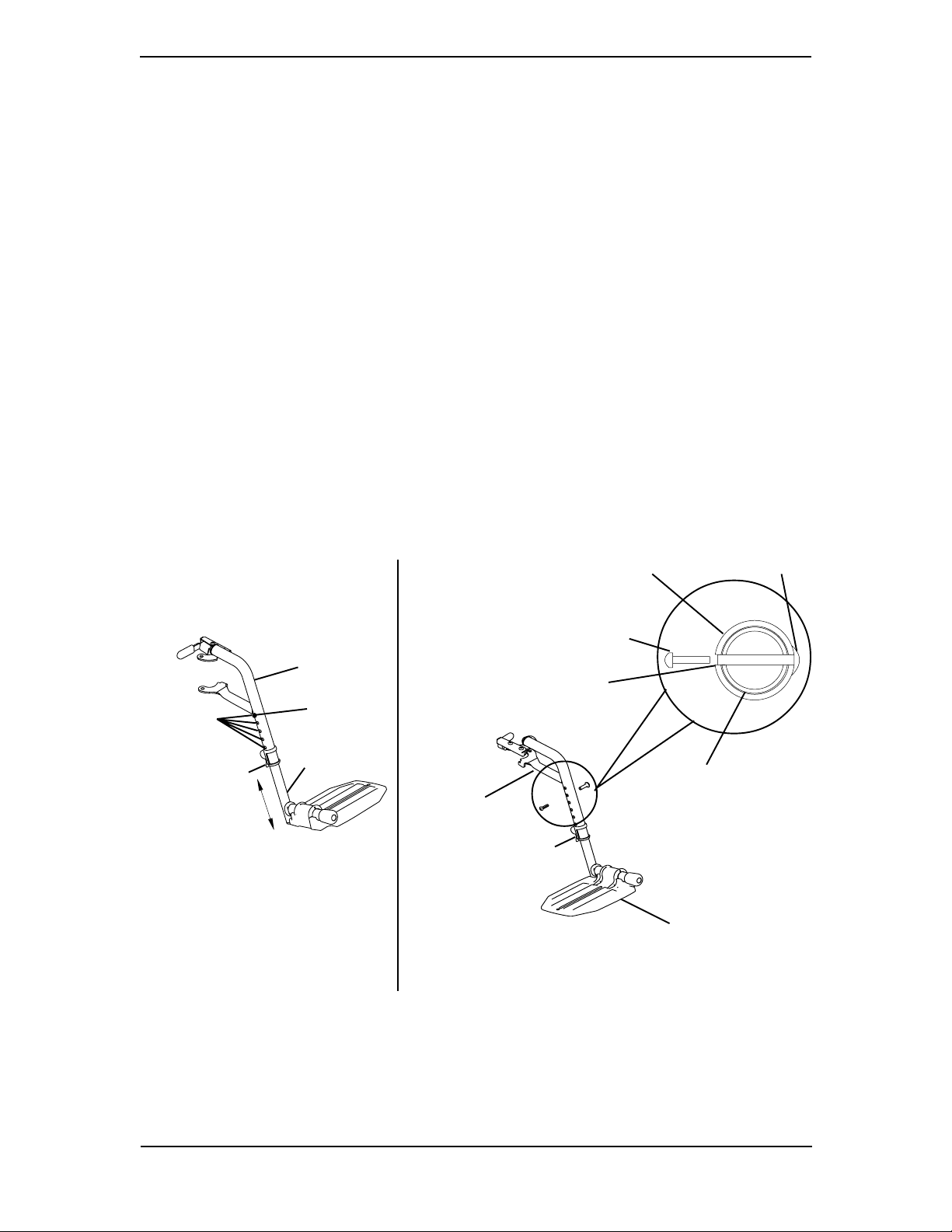
INSTALLING THE BOLT-IN-PLACE FOOTPLATE KIT
(FIGURE 1)
NOTE: This kit mounts the footplate assembly to the front rigging support so that tools are required
to remove or adjust the footrest assembly.
1. Remove the front rigging from the wheelchair. Refer to the wheelchair owner’s
manual shipped with wheelchair.
2. Pull up on the cam lock lever to unlock the cam.
NOTE: The elevating legrest has two (2) sets of release buttons, one (1) set above the other. Each
set will be visible one at a time allowing finer footplate height adjustment.
3. Push IN and hold the release button as shown in DETAIL “A” of FIGURE 1.
4. Rotate the lower footplate assembly 1/4 turn.
Part No. 1114831 1 Bolt-In-Place/Spring Button
Front Rigging Kit
Page 2
5. Remove the lower footplate assembly from the front rigging support.
6. Squeeze and push the release button down to remove from the footplate tube.
7. Ensure the cam lock lever is UP and unlocked.
8. Insert the footplate tube into the front rigging support.
9. Position the lower footplate assembly to the desired height.
10. Align the adjustment holes in the front rigging support and footplate assembly.
11. From the outside of the swingaway front rigging, insert the riv nut through both the
front rigging support and the footplate assembly.
12. From the inside of the swingaway front rigging, insert the button head screw through
the appropriate adjustment hole and thread into the riv nut.
13. Using a screwdriver to hold the riv nut in position, securely tighten the button head
screw. Torque to 32 in-lbs.
14. Push the cam lock lever DOWN to the locked position.
15. Reinstall the swingaway front rigging assembly. Refer to the owner’s manual that shipped
with wheelchair.
16. Repeat this procedure for the other footplate, if necessary.
DETAIL "A"
Front Rigging
Support
Release
Adjustment
Holes
Cam Lock Lever
Button
Footplate
Assembly
NOTE: Swingaway footrest shown.
Front Rigging Support
Button Head Screw
Adjustment Hole
Front Rigging
Support
Cam Lock Lever
INSIDE OF
SWINGAWAY
FRONT
RIGGING
Riv Nut
Footplate Assembly
OUTSIDE OF
SWINGAWAY
FRONT
RIGGING
Footplate Assembly
NOTE: Swingaway
footrests shown.
FIGURE 1 - INSTALLING THE BOLT-IN-PLACE FRONT RIGGING KIT
Bolt-In-Place/Spring Button 2 Part No. 1114831
Front Rigging Kit
Page 3

BOLT-IN-PLACE HEIGHT ADJUSTMENT (FIGURE 1)
NOTE: This procedure applies to the swingaway footrests and swingaway elevating legrest.
1. Remove the swingaway front rigging. Refer to INSTALLING/REMOVING THE
FRONT RIGGINGS in the owner’s manual shipped with wheelchair.
NOTE: Lay the front rigging assembly on a flat surface to simplify this procedure.
2. Pull the cam lock lever UP to UNLOCKED position.
3. Using a screw driver to hold the riv nut in position, remove the button head screw
from the riv nut.
4. Remove the riv nut and button head screw securing the footplate assembly to the
front rigging support.
5. Adjust the footplate assembly height by aligning the desired adjustment holes in the
upper front rigging support and footplate assembly.
6. From the outside of the swingaway front rigging, insert the riv nut through both the
front rigging support and the footplate assembly.
7. From the inside of the swingaway front rigging, insert the button head screw through
the appropriate adjustment hole and thread into the riv nut.
8. Using a screwdriver to hold the riv nut in position, securely tighten the button head
screw. Torque to 32 in-lbs.
9. Rotate cam lock lever DOWN to LOCKED position.
10. Repeat STEPS 1-9 to adjust the remaining footrest.
11. Reinstall the swingaway front rigging. Refer to INSTALLING/REMOVING THE
FRONT RIGGINGS in the owner’s manual shat shipped with wheelchair.
Part No. 1114831 3 Bolt-In-Place/Spring Button
Front Rigging Kit
Page 4

INSTALLING THE SPRING BUTTON FRONT RIGGING
KIT (FIGURE 2)
NOTE: This kit allows tool-less removal or adjustment of the footplate assembly.
1. Remove the front rigging from the wheelchair. Refer to the wheelchair owner’s
manual shipped with wheelchair.
\
2. Pull the cam lock lever UP to UNLOCKED position.
3. Using a screw driver to hold the riv nut in position, remove the button head screw
from the riv nut as shown in DETAIL “A” of FIGURE 2.
4. Remove the riv nut and button head screw securing the footplate assembly to the
front rigging support.
5. Remove the footplate assembly from the upper front rigging support.
6. Perform one of the following as shown in DETAIL “B” OF FIGURE 2:
A. FOOTRESTS:
• With the spring pointing UP, insert the spring button into the footplate tube
so that the release buttons FULLY protrude through the top set of mounting
holes.
B. ELEVATING LEGRESTS AND FOOTRESTS WITH ADJUSTABLE ANGLE
FOOTPLATES:
• With the spring pointing DOWN, insert the bottom spring button into the
footplate tube so that the release buttons FULLY protrude through the
bottom set of mounting holes.
• With the spring pointing UP, insert the top spring button into the footplate
tube so that the release buttons FULLY protrude through the top set of
mounting holes.
NOTE: The elevating legrest has two (2) sets of release buttons, one (1) set above the other. Each
set will be visible one at a time allowing finer footplate height adjustment.
7. Insert the footplate tube into the front rigging support.
8. Push IN the release buttons and reposition the footplate assembly to the desired
height.
9. Ensure that the release buttons fully protrude from holes on both sides of the front
rigging support.
10. Rotate cam lock lever DOWN to LOCKED position.
11. Reinstall the swingaway front rigging assembly. Refer to the owner’s manual shipped
with wheelchair.
12. Ensure Release buttons are properly seated and FULLY protrude through the
adjustment holes before use.
13. Repeat this procedure for the other footplate, if necessary.
Bolt-In-Place/Spring Button 4 Part No. 1114831
Front Rigging Kit
Page 5

DETAIL “A”
Front Rigging Support
Riv Nut
DETAIL “B”
Spring
Spring Button
Release Buttons
Front Rigging Support
Release
Button
Button
Head
Screw
Cam
Lock
Lever
NOTE: Swingaway
footrests shown.
Footplate
Assembly
FOOTRESTS
Spring
Top Spring Button
Release Buttons
Bottom Spring Button
Spring
Adjustment
Holes
Cam Lock
Lever
NOTE: Swingaway
footrest shown.
Footplate
Assembly
ELEVATING LEGRESTS/
FOOTRESTS WITH
ADJUSTABLE ANGLE
FOOTPLATES
FIGURE 2 - INSTALLING THE SPRING BUTTON FOOTPLATE KIT
SPRING BUTTON HEIGHT ADJUSTMENT (FIGURE 2)
NOTE: This procedure applies to the swingaway footrests and swingaway elevating legrest.
1. Remove the swingaway front rigging. Refer to INSTALLING/REMOVING THE
FRONT RIGGINGS in the owner’s manual shipped with wheelchair.
NOTE: Lay the front rigging assembly on a flat surface to simplify this procedure.
2. Pull the cam lock lever UP to UNLOCKED position.
NOTE: The elevating legrest has two (2) sets of release buttons, one (1) set above the other. Each
set will be visible one at a time allowing finer footplate height adjustment.
3. Push IN the release buttons and reposition the footplate assembly to the desired
height.
4. Ensure that the release buttons fully protrude from holes on both sides of the front
rigging support.
5. Rotate cam lock lever DOWN to LOCKED position.
6. Repeat this procedure for the other footplate, if necessary.
7. Reinstall the swingaway front rigging assembly. Refer to INSTALLING/REMOVING THE
FRONT RIGGING in the owner’s manual that shipped with wheelchair.
8. Ensure Release buttons are properly seated and FULLY protrude through the
adjustment holes before use.
Part No. 1114831 5 Bolt-In-Place/Spring Button
Front Rigging Kit
Page 6

NOTESNOTES
NOTES
NOTESNOTES
Bolt-In-Place/Spring Button 6 Part No. 1114831
Front Rigging Kit
Page 7

NOTESNOTES
NOTES
NOTESNOTES
Part No. 1114831 7 Bolt-In-Place/Spring Button
Front Rigging Kit
Page 8

Invacare Corporation www.invacare.com
USA
One Invacare Way Invacare is a registered trademark of
Elyria, Ohio USA Invacare Corporation.
44036-2125 Yes, you can. is a trademark of
800-333-6900 Invacare Corporation.
MADE IN MEXICO
© 2003 Invacare Corporation
Part No. 1114831 Rev B - 07/03
 Loading...