

Page 1
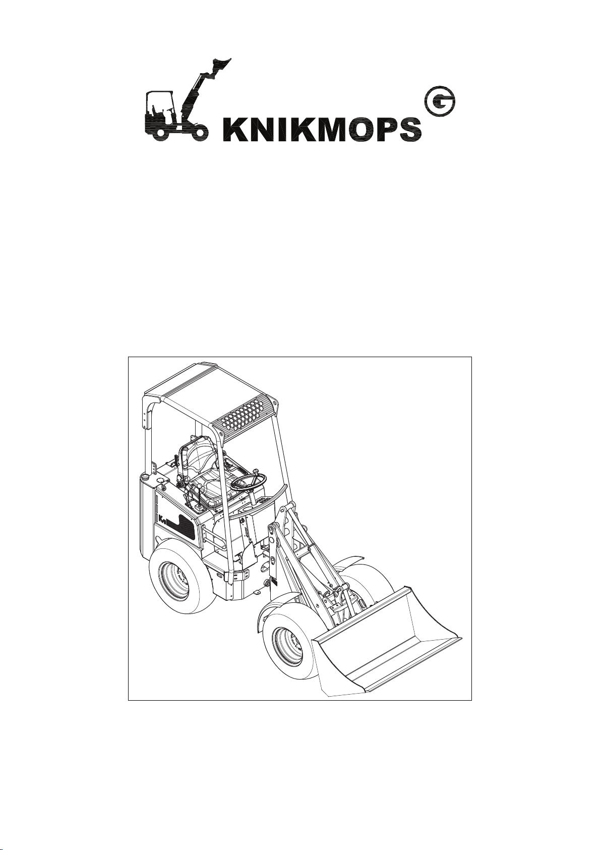
User Manual
Knikmops Wheel Loaders
Page 2

Introduction
Copyright and contact details
©
Miniloaders.com All rights reserved.
This document or parts thereof may not be reproduced, copied, distributed or stored in a search
system, or sent in any form or method, electronic or otherwise, without written permission from
Miniloaders.com.
Specifications and illustrations can be changed without prior notice. Miniloaders.com cannot be
held responsible for any change or typing error. Details and values mentioned in this document are
average values and determined with care. Details and values are not binding. Miniloaders.com
cannot be held liable for damage suffered as a result of reliance on the information provided in this
document or the use of products, processes or equipment to which this document refers.
2
Page 3

Preface
Make sure that the Knikmops wheel loader is always accompanied by this operator manual.
Miniloaders.com is not responsible for damage and indirect damage caused by operator error, lack
of (skilled) maintenance or any other use other than described in this manual. Miniloaders.com
cannot be held liable for any damages resulting from unauthorized modifications or additions to the
Knikmops wheel loader without the written consent of Miniloaders.com
Miniloaders.com continually strives to improve her products and services. We therefore reserve the
right to change the specifications in this operator manual at any time without prior notice.
The content of this manual has been prepared with the utmost care. Nevertheless, some
information may be incomplete, incorrect or may become outdated in time.
TO THE FULLEST EXTENT PERMISSIBLE BY LAW, MINILOADERS.COM MAKES NO
REPRESENTATIONS OR WARRANTIES OF ANY KIND, WHETHER EXPRESS OR IMPLIED,
FOR THE CURRENCY, ACCURACY OR COMPLETNESS OF ANY INFORMATION, AS
DEFINED ABOVE.
FURTHERMORE, MINILOADERS.COM MAKES NO REPRESENTATIONS OR WARRANTIES IN
CONNECTION TO ITS PRODUCTS AND/OR SERVICES, INCLUDING WARRANTIES ABOUT
ITS SERVICES’ AND PRODUCTS’ MERCHANTABILITY OR FITNESS FOR A PARTICULAR
PURPOSE, UNLESS EXPLICITLY MADE AND PROVIDED BY MINILOADERS.COM IN WRITING
TO THE PURCHASER OF THE SERVICES AND/OR PRODUCTS.
3
Page 4

Introduction
©
All rights reserved by Miniloaders.com
Use of the operator manual
This operator manual provides detailed operating procedures for safe, effective and proper
machine use. The manual includes chapters about safe operation, machine specification,
maintenance and troubleshooting information.
Improper operation, inspection and maintenance of the machine can result in injury or death. Read
and understand the contents of this manual completely and become familiar with the machine
before operation. Contact your authorized dealer with any questions about information in this
manual or if you need extra manuals or manuals in other languages.
This manual is considered a permanent part of the machine and should be with the machine at all
times. Replace this manual promptly if it becomes damaged, lost, or stolen.
Change of ownership
If the machine is resold, include this operator manual as part of the sale.
Please provide your dealer or Miniloaders.com with the name of the current owner and any new
address, along with the machine model and serial numbers. This makes sure that the registered
owner receives any updated information and can be notified directly in case of an important
product issue, such as a safety update program.
Warning: Do not remove this operator manual from this machine.
Failure to obey safety, operating and maintenance instructions can result in serious injury to the
operator or bystanders, poor operation and costly breakdowns of the machine.
If you have any questions on proper operation, adjustment or maintenance of this machine, contact
your dealer before starting or continuing operation.
4
Page 5

Contents
Contents
1 Introduction................................................................................................. 8
1.1 About this manual............................................................................................................................8
1.2 Revision history...............................................................................................................................8
1.3 Related documents......................................................................................................................... 8
1.4 Safety symbols in the document..................................................................................................... 9
1.5 Contact details for North America................................................................................................... 9
2 Safety........................................................................................................10
2.1 Intended use..................................................................................................................................10
2.2 Safety instructions.........................................................................................................................10
2.2.1 Using the machine.............................................................................................................10
2.2.2 Personnel.......................................................................................................................... 11
2.2.3 Organizational measures...................................................................................................11
2.2.4 Safety instructions during certain activities........................................................................12
2.2.5 Instructions concerning certain risks................................................................................. 12
2.2.6 Instructions concerning hydraulic parts............................................................................. 13
2.3 Safety symbols on the machine.................................................................................................... 13
3 Description................................................................................................16
3.1 Overview....................................................................................................................................... 16
3.2 Type plate......................................................................................................................................16
3.3 Dashboard.....................................................................................................................................17
3.3.1 Dashboard types............................................................................................................... 17
3.3.2 Dashboard type 1.............................................................................................................. 17
3.3.3 Dashboard type 2.............................................................................................................. 18
3.4 Hydraulic control............................................................................................................................18
3.5 Mounting plate...............................................................................................................................19
3.6 Sticker for hydraulic control and boom level functions.................................................................. 20
3.7 Driver’s seat.................................................................................................................................. 21
3.8 Operating principle: driving the wheels......................................................................................... 22
4 Daily use................................................................................................... 23
4.1 Starting..........................................................................................................................................23
Preparation....................................................................................................................................23
Start the machine.......................................................................................................................... 23
4.2 Stop...............................................................................................................................................24
4.3 Driving........................................................................................................................................... 24
4.3.1 Driving: safety instructions.................................................................................................24
4.3.2 Driving............................................................................................................................... 25
- - 5
Page 6

Contents
4.4 Operating the boom.......................................................................................................................25
4.5 Attaching an interchangeable accessory.......................................................................................25
4.6 Detaching an interchangeable accessory..................................................................................... 26
4.7 Refueling....................................................................................................................................... 27
4.8 Engaging and disengaging the differential.................................................................................... 28
4.9 Positioning counterweights............................................................................................................28
4.10 Mounting and removing the jib lock...............................................................................................29
4.11 Preheating.....................................................................................................................................30
4.12 Transport and storage...................................................................................................................30
Release the pressure in the hydraulic system for the auxiliary functions......................................26
Attaching....................................................................................................................................... 26
Positioning the first counterweight................................................................................................ 28
Positioning the second and third counterweight............................................................................29
Mounting....................................................................................................................................... 29
Removal........................................................................................................................................ 30
Charging........................................................................................................................................30
4.12.1 Transport: safety instructions............................................................................................ 30
4.12.2 Driving on the means of transport..................................................................................... 31
4.12.3 Hoisting the machine.........................................................................................................31
4.12.4 Storage..............................................................................................................................31
5 Maintenance............................................................................................. 32
5.1 Daily maintenance.........................................................................................................................32
5.2 Maintenance table: maintenance with the machine switched off.................................................. 32
5.3 Maintenance table: maintenance with the machine switched on.................................................. 33
5.4 Periodic maintenance (qualified service technician)..................................................................... 33
5.5 Opening the engine compartment.................................................................................................34
Opening the engine compartment: type 1 (KM80 to KM100)........................................................34
Opening the engine compartment: type 2 (KM120)...................................................................... 35
5.6 Clean the pre-filter.........................................................................................................................35
5.7 Check the fan belt tension.............................................................................................................36
5.8 Checking the parking brake...........................................................................................................36
5.8.1 Lubricate the hinge points................................................................................................. 37
5.8.2 Procedure: lubrication via grease nipples..........................................................................37
5.8.3 Grease nipples standard versions.....................................................................................37
5.8.4 Grease nipples TE versions.............................................................................................. 38
5.9 Check/top up the engine oil level.................................................................................................. 38
5.10 Check/top up the coolant fluid level...............................................................................................39
Check............................................................................................................................................ 39
Topping up.................................................................................................................................... 39
5.11 Check and top up the hydraulic fluid level.....................................................................................40
5.12 Replace the air filter...................................................................................................................... 40
Remove the cover......................................................................................................................... 40
Replace the filter........................................................................................................................... 41
6 - -
Page 7

Contents
5.13 Replacing the hydraulic fluid filters................................................................................................41
Replace the intake filter.................................................................................................................41
Replacing the return filter (only present on certain machine types).............................................. 42
5.13.1 Other lubrication points......................................................................................................42
5.13.2 Procedure: lubrication via grease nipples..........................................................................42
5.13.3 Other lubrication points......................................................................................................43
6 Resolving problems.................................................................................. 44
6.1 Daily maintenance.........................................................................................................................44
6.2 Troubleshooting table....................................................................................................................44
7 Technical data.......................................................................................... 46
7.1 Consumables................................................................................................................................ 46
7.2 Reference figure: dimensions........................................................................................................46
7.3 Reference figure: maximum load.................................................................................................. 47
7.4 KM80.............................................................................................................................................48
7.5 KM85.............................................................................................................................................49
7.6 KM100...........................................................................................................................................50
7.7 KM100TE...................................................................................................................................... 51
7.8 KM120...........................................................................................................................................52
7.9 KM120TE...................................................................................................................................... 53
- - 7
Page 8
Introduction
1 Introduction
1.1 About this manual
The Knikmops wheel loader is referred to in the rest of this manual by the term
"machine".
This manual is intended for the following target groups:
• Machine operator
• Personnel that carry out daily maintenance on the machine
The manual is applicable for these machine types:
• KM80
• KM85
• KM100
• KM100TE
• KM120
• KM120TE
This manual was originally written in Dutch. All other language versions are translations.
If there is any doubt about the correctness of a translation, the Dutch version takes
precedence.
It is not always possible to show a detailed image of each individual part of the machine.
Therefore, the images in this document can only show a standard layout. The images are
for instruction purposes only.
1.2 Revision history
Date
November 2017 001 First version
August 2018 002
Revision Note
1.3 Related documents
Document type
User Manual 34 - X - Y
Adjustment of the hours for maintenance
Adjustment of contact details naar Miniloaders.com
Document number Target group
• Operator
• Personnel that carry out daily
maintenance on the machine
Diesel engine user manual 16622-8916-8 Qualified maintenance technician
• X: version number of the document
• Y: release date of the document
8 11 - 002 - 30.08.2018
Page 9
1.4 Safety symbols in the document
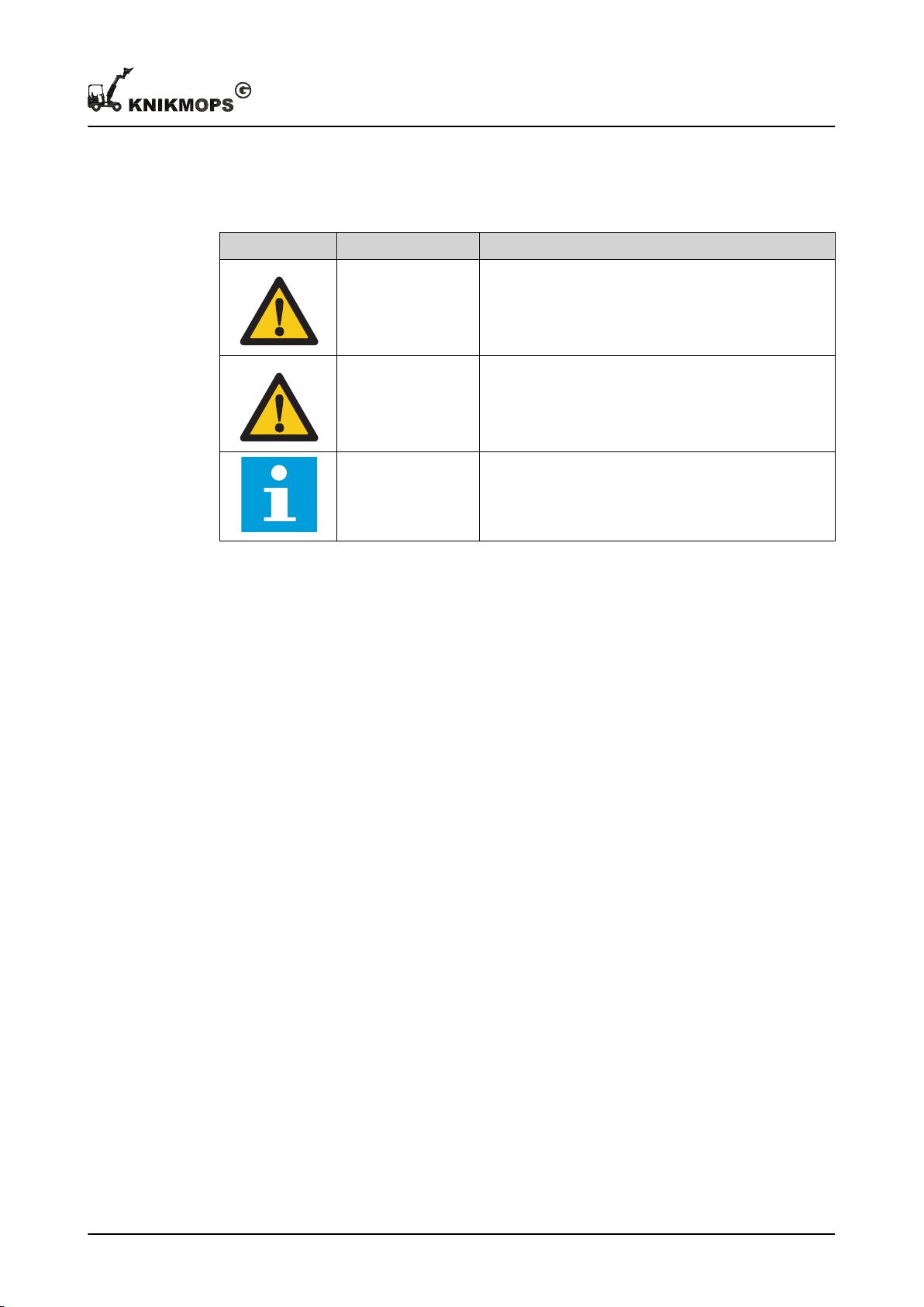
Safety symbol Purpose Description
Warning "Warning" means that injury or death is possible if you
do not obey the instructions.
Caution "Caution" means that damage to the equipment is pos-
sible if you do not obey the instructions.
Note "Note" is used to provide additional information.
Introduction
1.5 Contact details for North America
Miniloaders.com
801 East Second Street
79045 Hereford, TX
Tel. 806-376-0166
E-mail: [email protected]
11 - 002 - 30.08.2018 9
Page 10

Safety
2 Safety
2.1 Intended use
The machine is made for carrying out excavation and transport work in road construction,
landscaping and related sectors. By connecting and disconnecting interchangeable
accessories, the machine can be used for different applications.
Use only interchangeable accessories intended for your machine and that have been
approved by the manufacturer.
2.2 Safety instructions
2.2.1 Using the machine
• Read the manual carefully before using the machine.
• Carry out the procedures in the order shown and complete the procedures.
• Keep this manual with the machine. If there is no manual, report it to your employer.
• Replace a damaged safety cabin immediately.
• If there is a fault or damage to the machine, stop the machine and report it to your
employer. Make sure that the fault is resolved immediately.
• Do not modify the machine unless approved in writing by the manufacturer in
advance.
• If the machine is fitted with an interchangeable accessory for which a periodic
inspection is required, proof of this inspection must accompany the machine at all
times.
• Use only interchangeable accessories from the manufacturer.
If using other interchangeable accessories, the manufacturer accepts no responsibility
for the use of the entire combination.
• When using an interchangeable accessory, subtract the weight of the interchangeable
accessory from the load values.
• Use the machine and the interchangeable accessory only as intended. If you want to
use the machine for another application, please contact the manufacturer.
• The manufacturer is not responsible for damage caused by improper use of the
machine or the interchangeable accessory.
• When replacing parts: always contact the manufacturer and only use parts that have
been approved by the manufacturer.
• Use personal protective equipment: safety clothing, safety footwear.
• Use hearing protection. The noise level is more than 93 dB(A).
• Keep the driver's seat, pedals and steps clean.
• Store materials and tools when you are not using them.
• Loads:
• Position loads only as indicated in this document.
• Do not exceed the maximum loading. For the specifications, see chapter #.
• Avoid asymmetrical distributions of the load.
10 11 - 002 - 30.08.2018
Page 11

Safety
• Counterweights:
• Only counterweights and the counterweight frame from the manufacturer may be
placed on the rear of the machine.
• Persons on the back of the machine are not allowed as counterweight.
• Ensure that the interchangeable accessory parts are properly secured at all times.
• Driving on a slope:
• Driving parallel to the slope is only permitted if the following conditions are met:
• Maximum slope 10°
• Boom retracted and as low as possible close to the ground
• Maximum speed 3 km/h
• Driving on slopes greater than 10° is only permitted if you drive straight up or
straight down, i.e. at right angles to the slope.
• Driving with loads on a slope is only permitted if the following conditions are met:
• Maximum slope 10°
• Load as low as possible close to the ground
• Maximum speed 3 km/h
• If the machine overturns:
• Keep your seat belt on.
• Stay on the machine.
• Turn off the machine completely.
• Always use the locking pin or locking pins to lock interchangeable accessories and
also follow the instructions of the interchangeable accessory.
• Obey the local labor and safety laws and environmental regulations.
2.2.2 Personnel
• The machine may only be used, maintained and repaired by personnel trained by the
manufacturer or by the importer.
• The personnel must:
• be 18 or older.
• be physically and mentally healthy.
• have the relevant knowledge and skills.
• Personnel in training may only use the machine under the supervision of trained
personnel.
2.2.3 Organizational measures
• Do not wear loose clothing or jewelry. Tie up long hair.
• Ensure that all warning symbols on the machine are legible. Replace unreadable
warning symbols immediately.
• Hoisting and lifting tools such as chains, plastic hoisting belts and steel straps must
meet these requirements:
• Be sufficiently strong, correctly dimensioned and in good condition
• Comply with local labor and safety laws
• Workplace environment:
11 - 002 - 30.08.2018 11
Page 12

Safety
• The machine is suitable for driving on the public highway, provided it has the
correct registration documents, the correct traffic lighting and permits.
• The workplace must be sufficiently lit at all times.
• It is the responsibility of the operator to ensure that bystanders (people who are not
the operator) cannot get into the path of the machine, the interchangeable
accessories or the loads.
2.2.4 Safety instructions during certain activities
• Make sure that no one is at risk.
• If there is danger, give a warning signal and stop the machine if necessary.
• Before using the machine, allow the machine to warm up in a well-ventilated area.
• If you do not have sufficient visibility, make sure you are assisted by trained
personnel. This personnel must be recognizable and stay within your field of vision at
all times.
• The machine must not be used in landfills where there is a risk of the machine falling,
unless there are provisions that prevent rolling or crashing.
• When you are no longer using the machine, stop the machine.
• Before stopping the machine, remove the interchangeable accessory according to the
instructions in this manual and place the interchangeable accessory in a safe location.
• If the hydraulic steering cylinder fails, fit the jib lock rod. See section
• At all times prevent persons going under the load.
• People must remain at a distance of 5 meters from the working machine.
• Explore the surrounding area and remove any obstacles.
4.10
.
2.2.5 Instructions concerning certain risks
• Make sure you know where the fire extinguishers are.
• In the event of fire: keep a sufficient distance away from the machine. If the hydraulic
fluid lines overheat, they can break and cause flash fires of burning hydraulic fluid.
• Use only fuses from the manufacturer.
• Avoid prolonged overloading of the hydraulics. This causes overheating of the
machine. Always ensure that the hydraulic control is in the neutral position when
starting the machine.
• Check the hydraulic fluid level daily and top up if necessary.
• Replace the hydraulic fluid filters and the hydraulic fluid at least once a year.
• Be careful when using hydraulic fluid and battery acid.
• Avoid high speeds with a low oil temperature: drive for the first 5 minutes at an
increased engine speed (1500 rpm), without a load.
• Refueling:
• Before refueling:
• Switch off all electrical systems.
• Switch off the engine and allow the engine and exhaust to cool down to a handwarm temperature.
• Refuel in a well-ventilated area.
• Do not refuel near open flames or sparks.
• Do not smoke while refueling.
• Make sure that no fuel, oil or grease gets on the machine.
• Only use the machine in well-ventilated areas.
• Only use original parts from the manufacturer.
12 11 - 002 - 30.08.2018
Page 13
• Avoid shocks and vibrations.
U
C
A
E
F
A
I
N-O
I
M
S
T
L
I
P
K
K
L
G
H
Q
J
R
B
J
D
V
• Do not use the machine as an anchor point.
2.2.6 Instructions concerning hydraulic parts
The machine and its attachments contain hydraulic components. These involve specific
dangers:
• The hydraulic oil heats up during use. Contact with hot hydraulic oil can lead to burns.
• The hydraulic oil is under high pressure. Hydraulic oil that sprays out of the system
under pressure can penetrate the skin and cause serious injuries. Therefore, never
look for leaks by feeling with your bare hand and use the necessary personal
protective equipment.
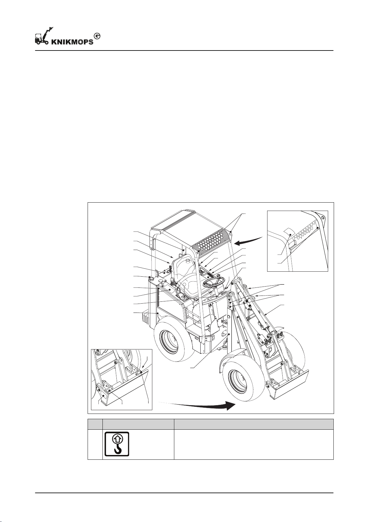
2.3 Safety symbols on the machine
Safety
11 - 002 - 30.08.2018 13
Symbol
A Only attach the lifting hooks to these locations for transport.
Meaning
Page 14
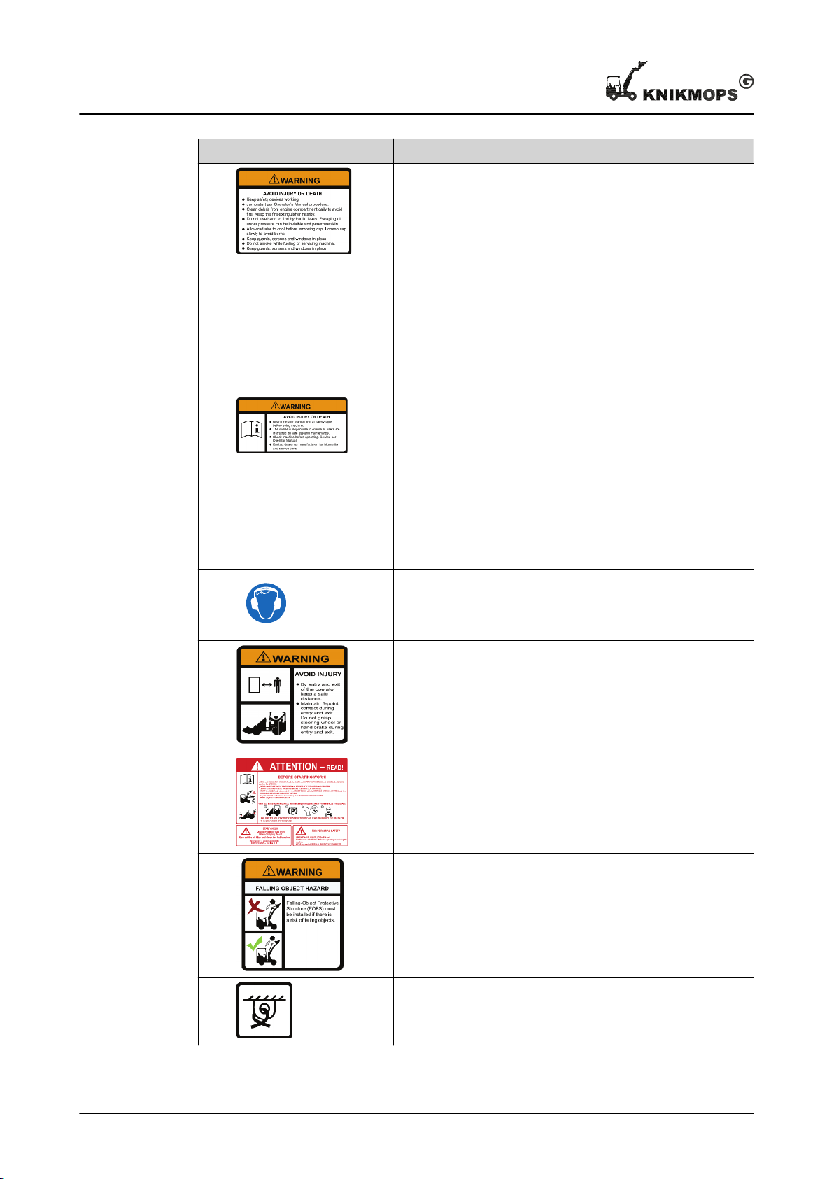
Safety
Symbol Meaning
B WARNING: Prevent personal injury or risk of death.
• Ensure that safety devices are active.
• Work according to the procedures in the user manual.
• Keep safety guards in place.
• It is forbidden to smoke during maintenance of the machine
or refueling.
• Remove all dirt from the engine compartment every day to
prevent fire. Keep a fire extinguisher nearby.
• Look for hydraulic leaks without using your hands.
• Escaping oil under pressure can be invisible and penetrate
the skin.
• Allow the engine heating to cool down before opening the
engine cap. Open the engine cap slowly to prevent burns.
C
D The operator is advised to use hearing protection.
E WARNING: Prevent physical injuries while getting in and out of
F Read the safety instructions before starting the machine. Obey
WARNING: Prevent personal injury or risk of death.
• Read the manual and all safety stickers before using the
machine.
• The owner is responsible for ensuring that all users of the
machine have been instructed about safe use and maintenance.
• Check the machine before every use. Use the operator
manual for this.
• Contact the supplier or manufacturer for information and
spare parts.
the machine:
• Keep some distance from the machine.
• Ensure you have a 3-point contact with the machine while
getting in or out.
• Do not hold the steering wheel.
these safety instructions.
G WARNING: It is forbidden to remove the FOPS.
H During transport, attach the straps only to these locations.
14 11 - 002 - 30.08.2018
Page 15
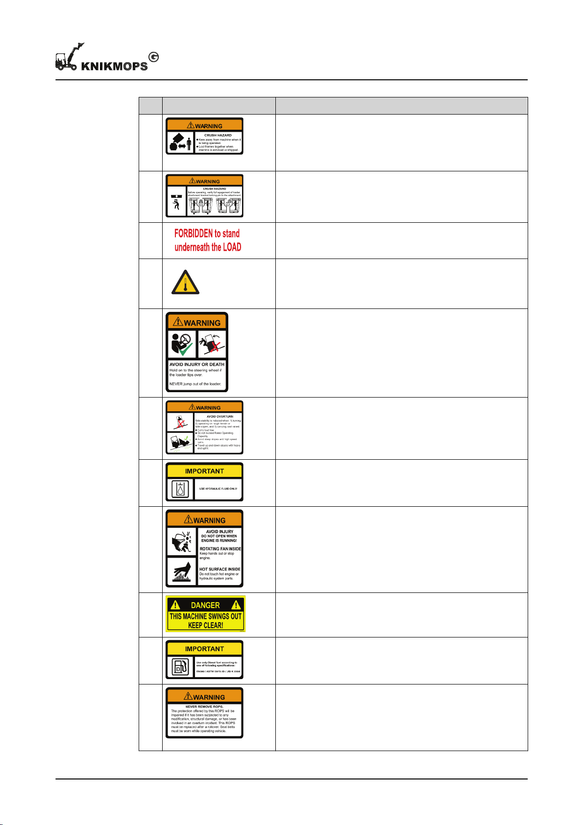
Symbol Meaning
I WARNING:
• Personnel not controlling the machine must remain at a
safe distance from the machine.
• Fit the jib lock for maintenance or transport.
J WARNING:
• Before starting the machine, ensure that the interchangeable accessory is secured with both locking pins.
K It is forbidden to stand under the load.
L CAUTION: high temperatures.
M WARNING: Prevent personal injury or risk of death.
• Keep hold of the steering wheel if the machine tilts.
• Never jump out of the machine.
Safety
N WARNING: Prevent the machine from tipping over.
• Keep the load low.
• Stay within the prescribed capacity.
• Avoid steep slopes and sharp turns.
O IMPORTANT: Only use hydraulic oil.
P WARNING:
• Do not put your hands into the machine when the engine is
running.
• Leave the engine cover closed when the machine is running.
• Risk of burns: hot machine parts under the cover.
Q DANGER: Stay at a safe distance. The machine swings out.
R IMPORTANT: Only use diesel that meets the stated specifica-
tions.
S WARNING:
• Have the ROPS replaced immediately after the machine
has been tilted.
• Wear seat belts while using the machine.
11 - 002 - 30.08.2018 15
Page 16
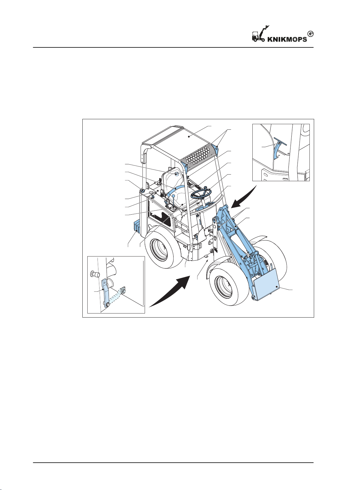
A
C
F
F
D
E
F
G
H
L
M
Q
F
N
O
J
K
P
I
P
B
Description
3 Description
3.1 Overview
A Safety cabin J Driver’s seat
16 11 - 002 - 30.08.2018
B Inching pedal K Counterweights (optional)
C Parking brake L Hydraulic control
D Steering wheel M Engine compartment
E Dashboard N Fuel tank
F Lifting eyes and tie-down points O Hydraulic fluid tank
G Boom P Jib locking pin
H Mounting plate Q Seatbelt
I Gas pedal
Page 17
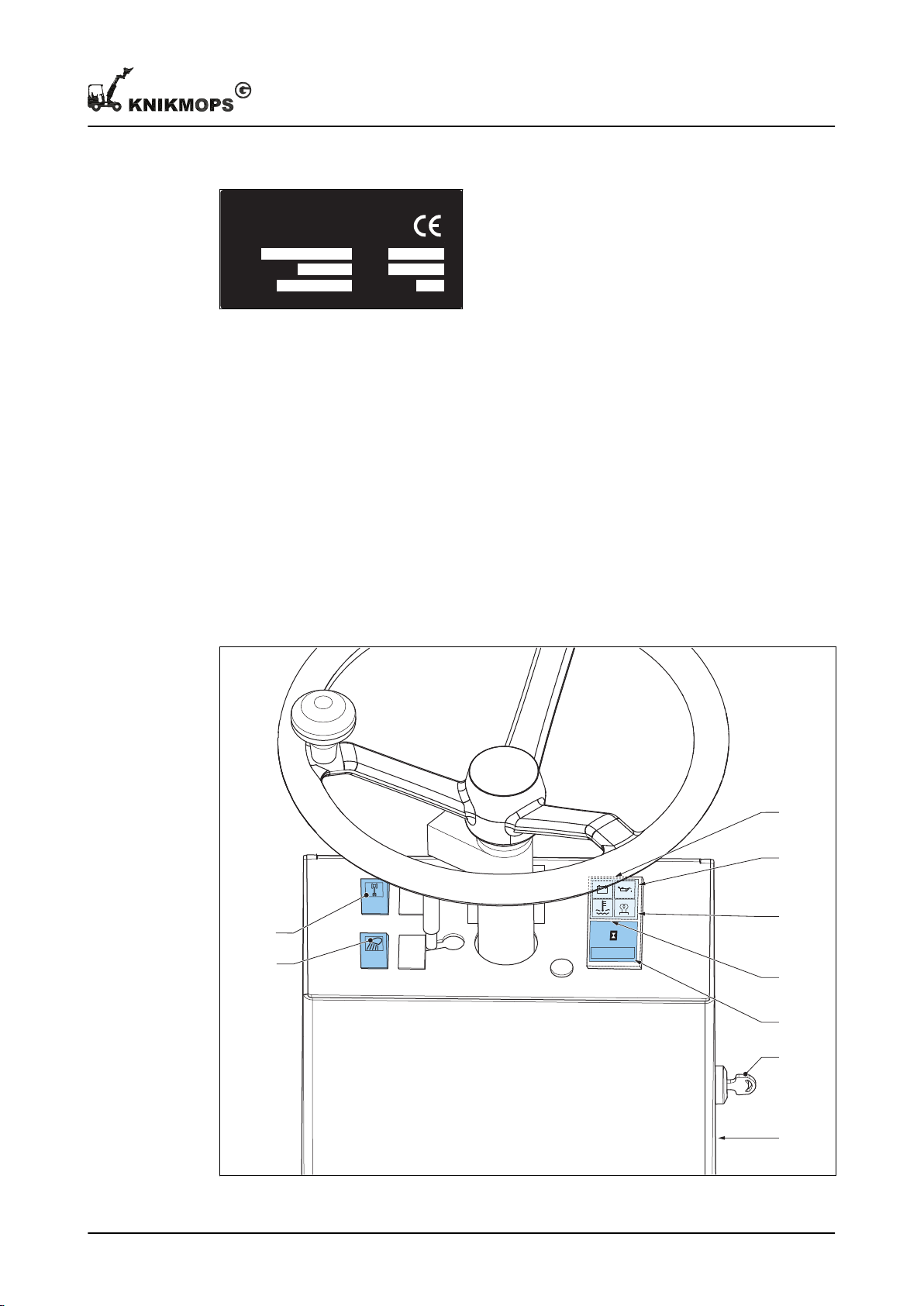
3.2 Type plate
MA SS/G EWI CH T
T YP E
SE RIE NR.
MA X. HY D R. 18 0 BAR
BO UWJ .
PO WER
MA X. LO AD /LA ST
KW
KG
MA DE I N BELGI UM
KG
0000000
E
F
G
H
I
C
D
A
B
The illustration shows an example of the layout of the type plate on the machine. The
actual type plate on the machine shows the correct data depending on the type of
machine.
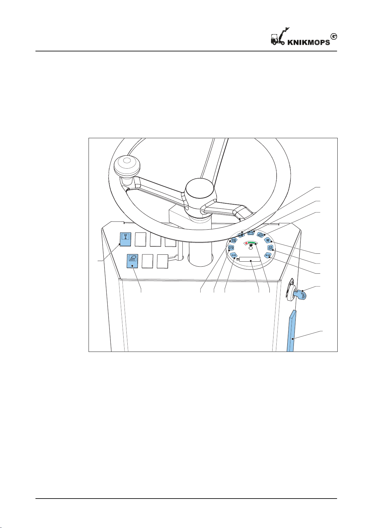
3.3 Dashboard
3.3.1 Dashboard types
Depending on the type of machine, there are different types of dashboard. All dashboards
contain the necessary control instruments.
Description
3.3.2 Dashboard type 1
A Ignition key F Oil pressure lamp
11 - 002 - 30.08.2018 17
Page 18
0000000
EONMC F
A
G
H
I
J
K
L
B
D
Description
B Fuse box G Pre-heater lamp for the diesel engine
C Light switch H Motor temperature lamp
D Differential switch I Operating hours counter
E Battery voltage lamp
3.3.3 Dashboard type 2
A Ignition key I Neutral position indicator
B Fuse box J Engine oil pressure
C Light switch K Battery voltage
D Differential switch L Engine coolant temperature
E Operating hours counter M Hydraulic fluid temperature
F Fuel indicator N Parking brake
G Turn signal (optional) O Position lights (optional)
H Pre-heater lamp for the diesel engine
18 11 - 002 - 30.08.2018
Page 19
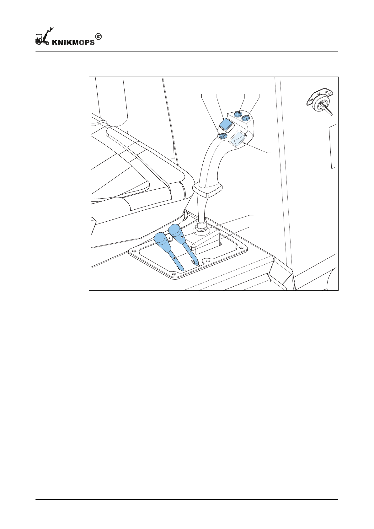
3.4 Hydraulic control
C D E F
G
B
A
Description
A Lever for auxiliary hydraulic function
left. See also section
B Lever for auxiliary hydraulic function
right. See also section
C Horn G Button to switch the electrical function
D Travel direction button
4.4
4.4
.
.
E Telescope button (extend) (only for TE
versions)
F Moving the joystick left and right takes
over the function of B.
of the attachment on and off.
11 - 002 - 30.08.2018 19
Page 20
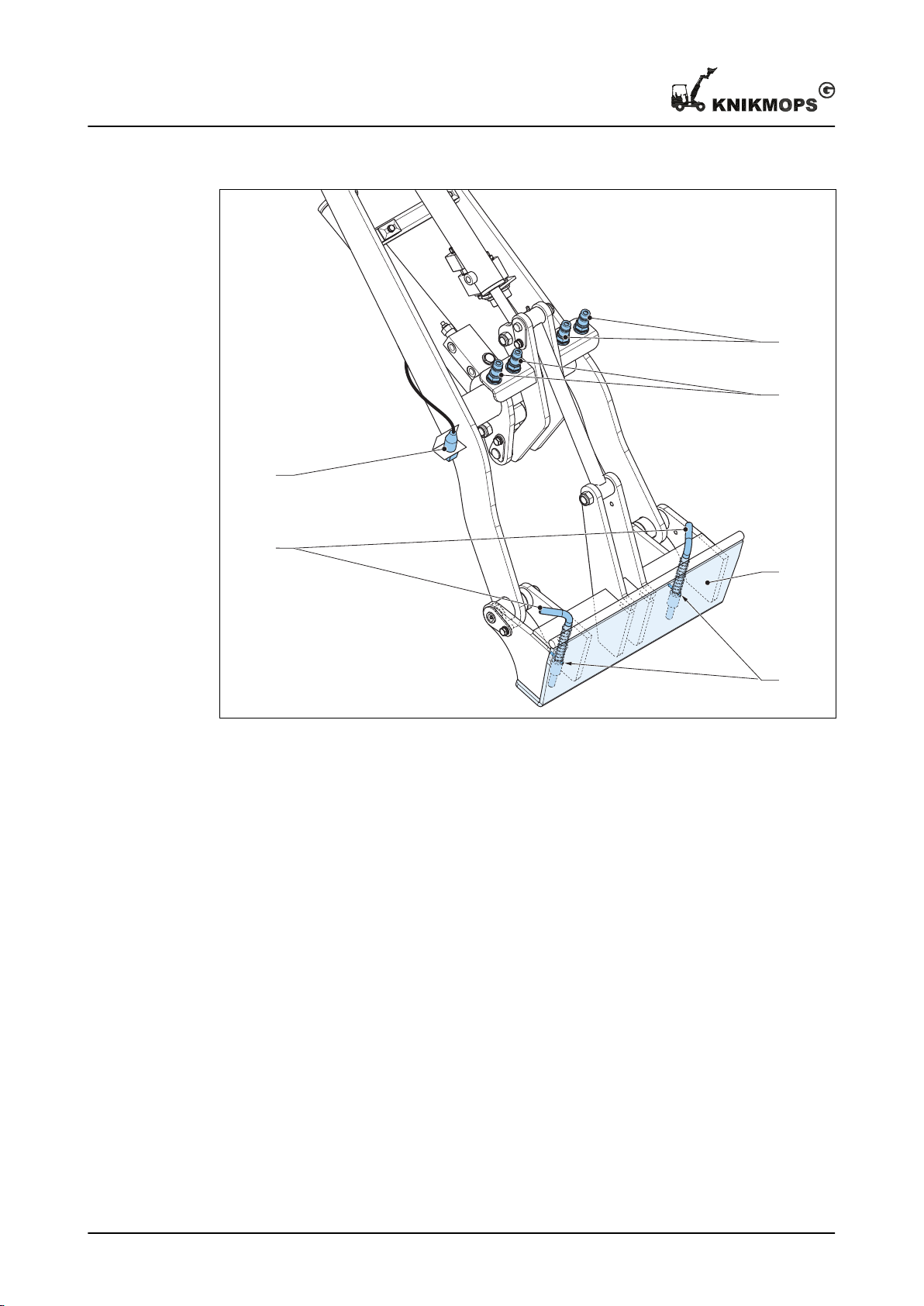
C
B
D
F
A
E
Description
3.5 Mounting plate
A Electrical connection for electrical
function.
B Connection for auxiliary hydraulic
function right.
C Connection for auxiliary hydraulic
function left.
D Mounting plate
E Locking handles
F Locking pins
20 11 - 002 - 30.08.2018
Page 21
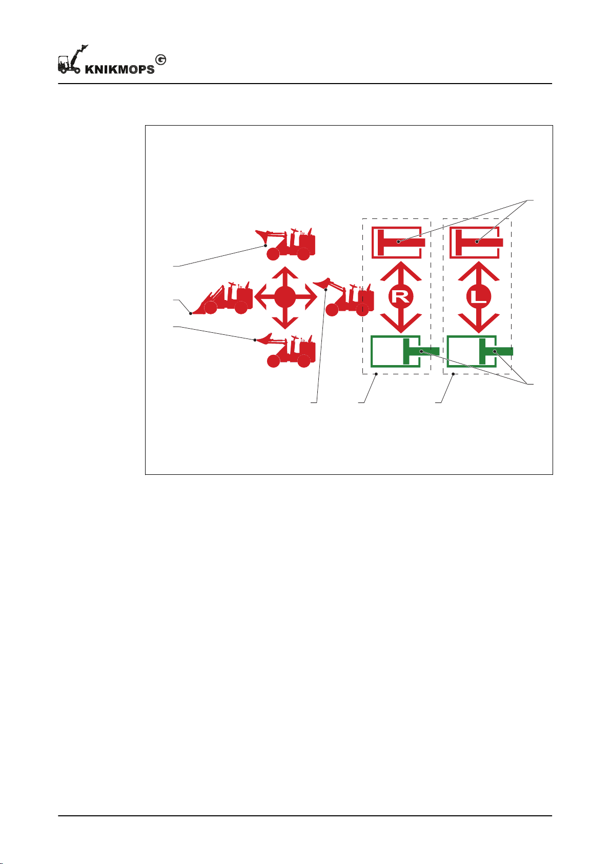
3.6 Sticker for hydraulic control and boom level functions.
G
C
A
D
EB F
H
Description
A LOWER BOOM E Auxiliary hydraulic function right
B RAISE BOOM F Auxiliary hydraulic function left
C MOUNTING PLATE FORWARDS G Hydraulic pressure on side hydraulic
connection with red dust cap
D MOUNTING PLATE BACKWARDS H Hydraulic pressure on side hydraulic
connection with green dust cap
11 - 002 - 30.08.2018 21
Page 22
C
B
D
BA
Description
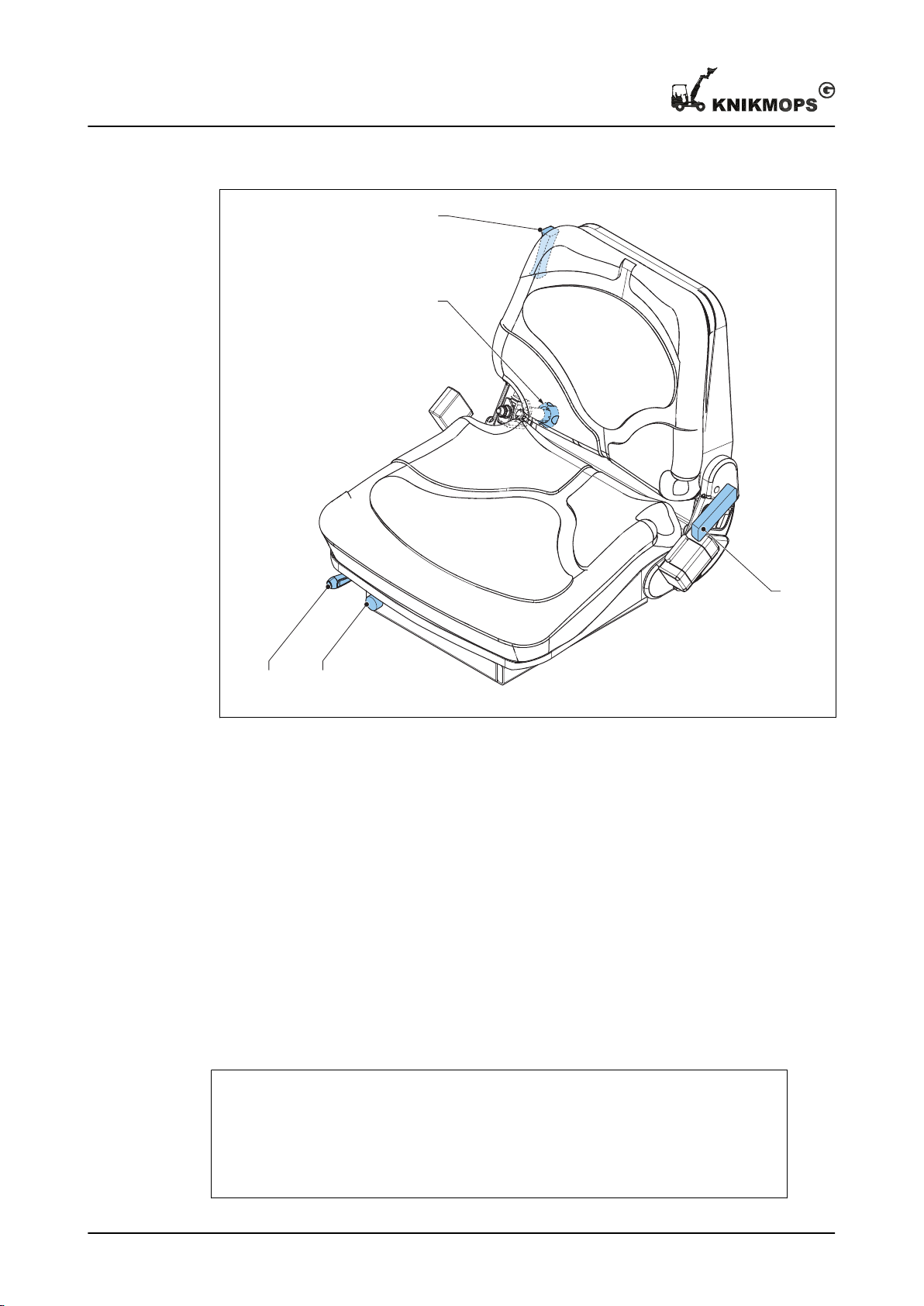
3.7 Driver’s seat
A Lever for adjusting the driver's seat
forwards and backwards
B Knob for driver weight adjustment D Handle for adjusting the backrest
Depending on the type of machine, the adjustments of the driver's seat may differ.
C Knob for adjusting the backrest
angle
3.8 Operating principle: driving the wheels
Hydraulic wheel motors drive the wheels of the machine, one motor per wheel. The
hydraulic pressure comes from a hydraulic pump that is driven in turn by a diesel engine.
The gas pedal of the machine controls the speed of the diesel engine and thus indirectly
the power and the speed of the hydraulics. The inching pedal can be used as a brake
pedal.
Example
You can use the inching pedal simultaneously with the gas pedal, for example to
drive slowly across rough terrain or to lift heavy loads slowly. Simultaneously
operate the gas pedal (for the power) and the inching pedal (to limit the speed).
When you press the inching pedal all the way in, the machine stops.
22 11 - 002 - 30.08.2018
Page 23

4 Daily use
ON
OFF
GL
ST
4.1 Starting
Safety
Warning: Do not exceed the maximum loading. For the specifications, see
chapter #.
Preparation
Daily use
1. Make sure that the daily maintenance has been carried out. See section
2. Check the fuel level and the hydraulic fluid level. Top up the relevant tank if
necessary.
4.7
• Topping up the fuel: see sectie
• Check and top up the hydraulic fluid: see section
3. If you are going to drive in a dusty environment, make sure the pre-filter is usable. If
necessary, clean or replace the pre-filter. See section
4. Make sure that the following controls are in the neutral position:
• Driving direction lever
• Boom lever
• Both levers for the auxiliary hydraulic functions
5. Sit on the driver's seat before starting the machine.
6. Adjust the driver's seat if necessary.
7. Put on the seatbelt and click it tight.
.
5.11
.
5.2
.
Start the machine
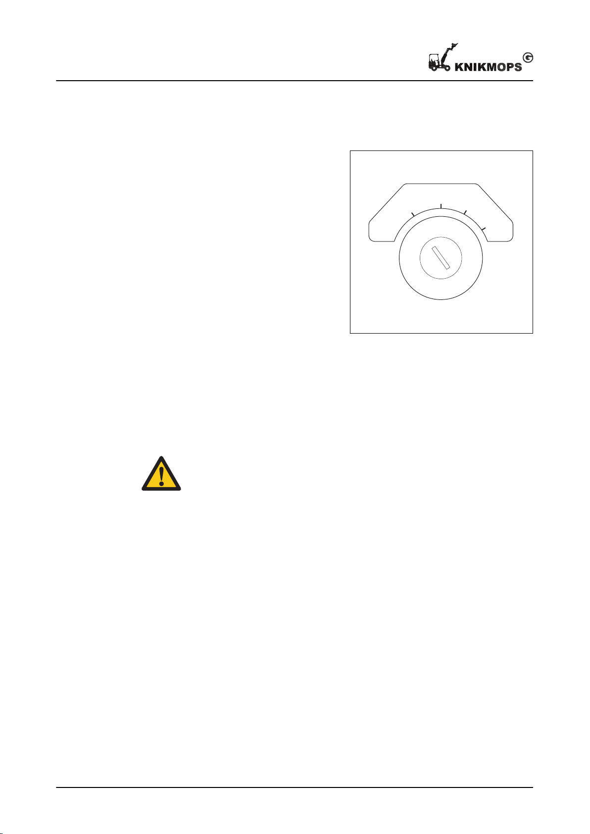
1. Insert the ignition key into the
ignition.
2. Turn the ignition key to the 'ON'
position. Check that the following
lamps are lit:
a) Battery voltage lamp
b) Oil pressure lamp
3. Turn the ignition key to the 'GL'
position. Wait until the pre-heat lamp
goes out.
4. Turn the key to the 'ST' position and
release the key as soon as the
engine is running.
5.1
.
11 - 002 - 30.08.2018 23
Page 24
ON
OFF
GL
ST
Daily use
4.2 Stop
1. Stop the machine on flat ground if
possible.
2. Place the boom on the ground, if no
load is present, or place the load on
the ground.
3. Pull the parking brake fully up.
4. Put the following controls in the
neutral position:
a) Driving direction lever
b) Boom lever
c) Both levers for the auxiliary
5. Turn the key to the 'OFF' position.
6. Remove and retain the key.
hydraulic functions
4.3 Driving
4.3.1 Driving: safety instructions
Warning:
• Try to avoid slopes and obstacles as much as possible. The machine can
become unstable.
• Driving on a slope:
• Driving parallel to the slope is only permitted if the following conditions
are met:
• Maximum slope 10°
• Boom retracted and as low as possible close to the ground
• Maximum speed 3 km/h
• Driving on slopes greater than 10° is only permitted if you drive straight
up or straight down, i.e. at right angles to the slope.
• Driving with loads on a slope is only permitted if the following conditions
are met:
• Maximum slope 10°
• Load as low as possible close to the ground
• Maximum speed 3 km/h
• Always drive with the boom retracted.
• Do not transport people with the machine.
• Do not make sharp turns at high speeds.
• Do not take of your seatbelt.
• Avoid high speeds with a low oil temperature: drive for the first 5 minutes
at an increased engine speed (1500 rpm), without a load.
• Do not exceed the maximum loading. For the specifications, see chapter 7.
24 11 - 002 - 30.08.2018
Page 25
4.3.2 Driving
A
F
N
R
1
4
2
3
A B
1. Press the parking brake button and fully lower the parking brake.
2. Choose a driving direction:
a) If you want to drive forwards, set
b) If you want to drive in reverse,
When the drive direction knob is in
the 'NEUTRAL’ position (N), the
machine will not move.
3. When you want to drive, press the
gas pedal.
4. When you want to brake, release the
gas pedal and press the inching
pedal.
Daily use
the direction button (A) to the
'FORWARD' position (F).
set the direction button (A) to the
'REVERSE’ position (R).
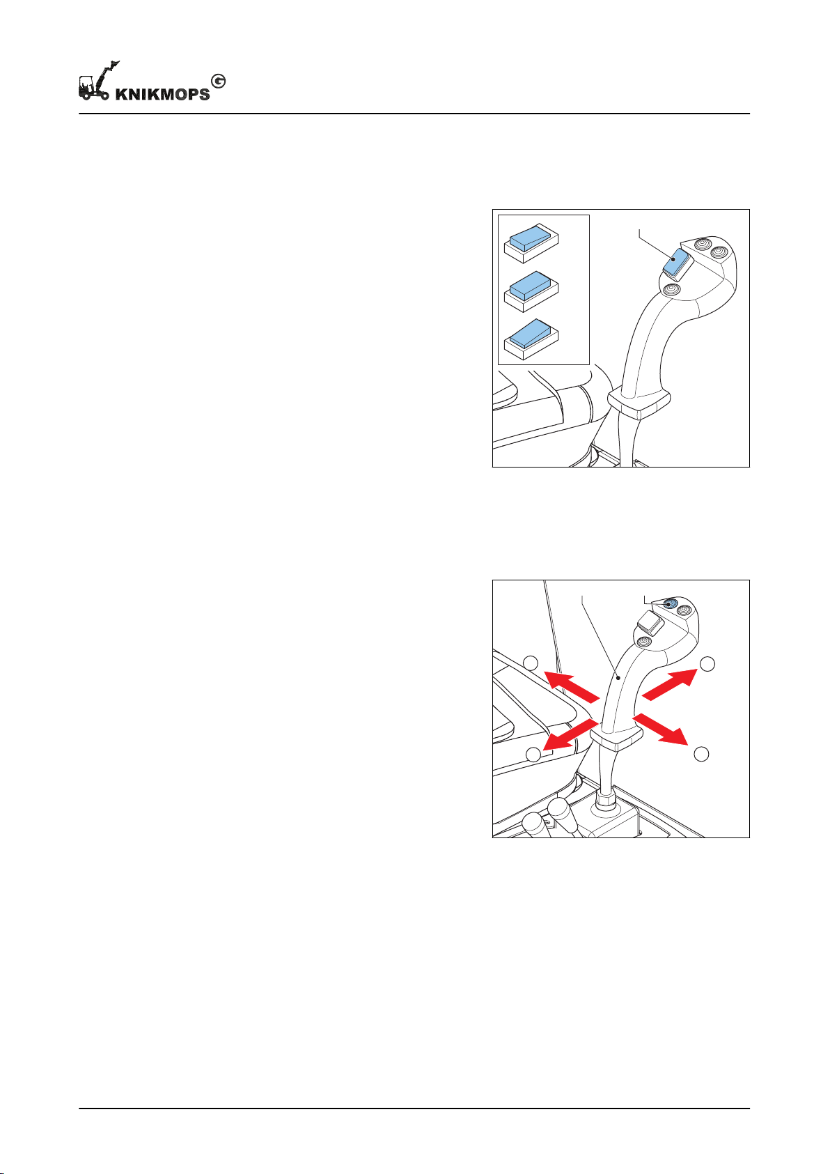
4.4 Operating the boom
1. If you want to lower the boom, hold
the boom level (A) in the 'LOWER
BOOM' position (1).
2. If you want to raise the boom, hold
the boom level (A) in the 'RAISE
BOOM' position (2).
3. If you want to tilt the mounting plate
backwards, hold the boom lever in
the 'MOUNTING PLATE
BACKWARD' position (3).
4. If you want to tilt the mounting plate
forwards, hold the boom lever in the
'MOUNTING PLATE FORWARD'
position (4).
5. If you want to extend the boom (only
for TE versions):
a) Press and hold the telescope button (B).
b) Put the boom lever in the 'RAISE BOOM' position (2).
6. If you want to retract the boom (only for TE versions):
a) Press and hold the telescope button (B).
b) Put the boom lever in the 'LOWER BOOM' position (1).
11 - 002 - 30.08.2018 25
Page 26
C
B
A
Daily use
4.5 Attaching an interchangeable accessory
About this task
Procedure
Release the pressure in the hydraulic system for the auxiliary functions
1. Turn the ignition key to the 'OFF' position to switch off the engine.
2. Move the levers for the auxiliary hydraulic functions back and forth several times to
remove the hydraulic pressure.
Attaching
1. Position the machine just in front of
the interchangeable accessory that
you want to attach.
2. Place the boom in the lowest
possible position.
3. Tilt the mounting plate forward.
4. Move the machine forward until the
mounting plate makes contact with
the interchangeable accessory.
5. Raise the mounting plate until the
interchangeable accessory is
completely against the face of the
mounting plate. If necessary, tilt the
mounting plate backwards a little.
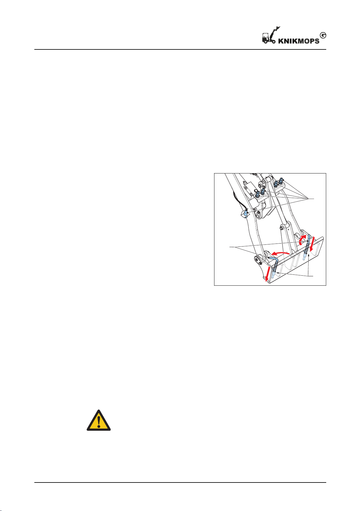
6. Put the locking pin levers (A) in the
locking position.
7. Check that the locking pins (B) have come out and secure the coupling of the
interchangeable accessory.
8. If necessary, connect the hydraulic hoses and electrical cables of the
interchangeable accessory to the connections for the auxiliary functions (C).
• Make sure the hydraulic quick release couplings are clean.
• Make sure the auxiliary functions are connected correctly. See also section
3.5
.
4.6 Detaching an interchangeable accessory
About this task
Caution:
When the interchangeable accessory is connected to the hydraulic quick
release couplings, first disconnect the auxiliary function connections before
disconnecting the interchangeable accessory from the machine.
26 11 - 002 - 30.08.2018
Page 27
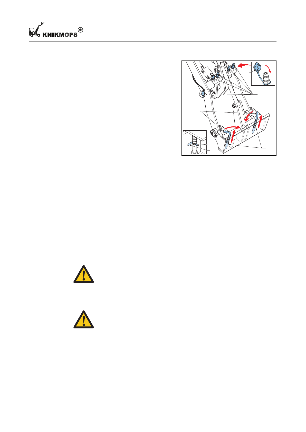
A
D
D
E
C
B
Daily use
Procedure
1. Place the interchangeable accessory
on the ground.
2. If auxiliary hydraulic functions are
connected:
a) Turn off the machine completely.
b) Move the lever for operating the
auxiliary hydraulic function that
you want to disconnect to and
fro to release the pressure in the
hydraulic system for the auxiliary
functions.
c) Disconnect the hydraulic hoses
of the interchangeable
accessory from the connections
for auxiliary functions (A).
d) Fit the dust covers (B) to the connections for the auxiliary functions.
3. Pull the lock pin levers (C) up and turn them a quarter turn until the lever pins (D) are
in the grooves (E).
The locking pins (F) are now pushed in and the interchangeable accessory is
unlocked.
4. Tilt the mounting plate forwards until the interchangeable attachment comes off the
mounting plate.
4.7 Refueling
Before you begin
The fuel is flammable and can be dangerous. Be careful when handling fuel.
Warning:
• Use only the right fuel and do not mix it with petrol or alcohol. Such a
mixture can damage the engine or cause an explosion.
• Do not spill fuel. If you do spill, remove spilled fuel immediately.
• Ensure that no open flames or sparks can occur when refueling.
• Only refuel in a well-ventilated area.
Caution: Make sure that the fuel tank is never emptied. If this happens, air can
get into the fuel system. In this case, the air must be removed from the fuel
system by a qualified service technician.
11 - 002 - 30.08.2018 27
Page 28
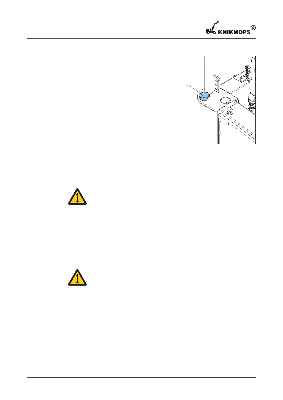
A
Daily use
Procedure
1. Stop the machine.
2. Remove the fuel cap (A).
3. Fill up with fuel.
For the correct type of fuel, see
section
4. Fit the fuel cap.
7.1
.
4.8 Engaging and disengaging the differential
About this task
Caution: In the event of improper use, the tires will show extra wear and the
machine will be difficult to steer.
Procedure
1. To engage or disengage the differential: press the differential switch.
4.9 Positioning counterweights
Safety
Warning: A minimum of two people are needed for lifting the counterweights.
Each counterweight weighs more than 30 kg.
28 11 - 002 - 30.08.2018
Page 29
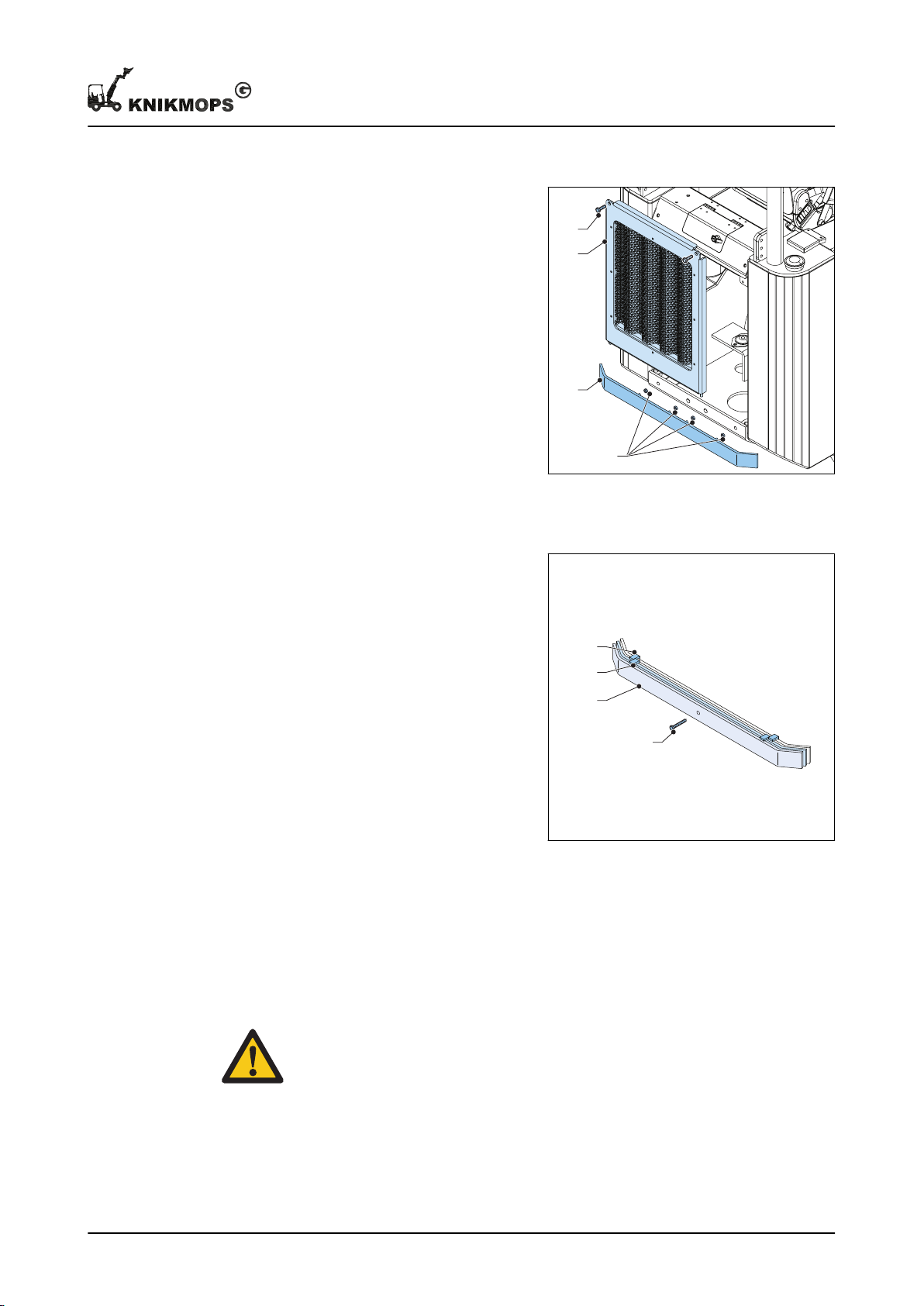
Positioning the first counterweight
D
C
A
B
A
C
B
B
1. Remove the bolts (A).
2. Remove the panel (B).
3. Position the counterweight (C).
4. Secure the counterweight with the
washers and the nuts (D).
5. Fit the panel.
6. Secure the panel with the bolts.
Positioning the second and third counterweight
Daily use
1. Hang the counterweight (A) on the
previous counterweight with the
hooks (B)
2. Fit the locking bolt (C).
4.10 Mounting and removing the jib lock
The jib lock is intended to prevent the machine from bending in the event of a failure of
the control mechanism.
Safety
Warning: Make sure the engine is switched off before you perform any actions
on the jib lock. If the engine is switched on, there is a risk of becoming
11 - 002 - 30.08.2018 29
trapped.
Page 30
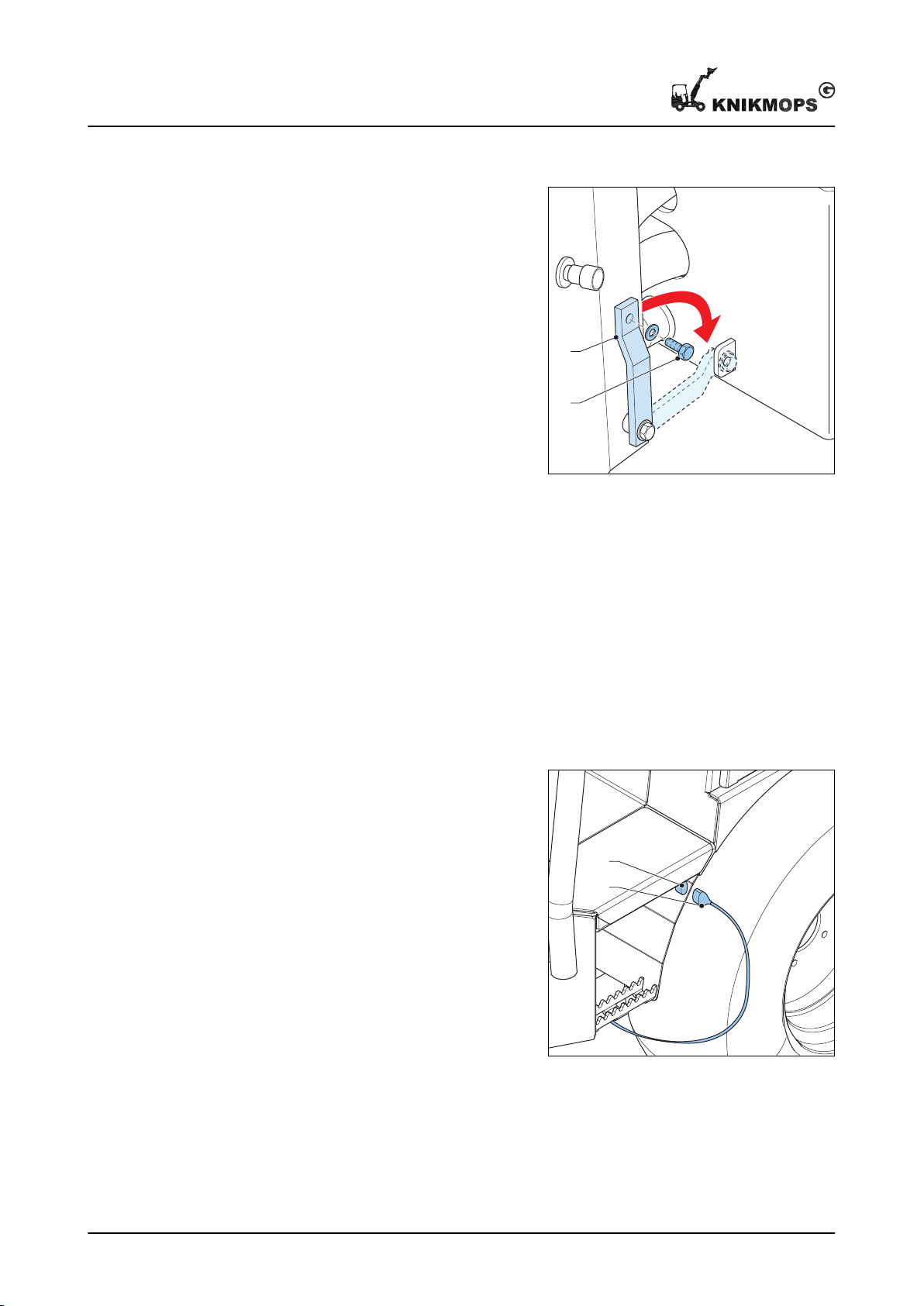
B
A
A
B
Daily use
Mounting
1. Switch the machine's engine off.
2. Remove the bolt (A).
3. Turn the jib lock (B) towards the tab
on the rear part of the machine.
4. Use the bolt (A) to secure the jib lock
to the tab.
Removal
1. Put the jib lock back on the front part of the machine.
4.11 Preheating
The machine has a built-in heating element.
Charging
1. Connect the machine to the wall
socket and the connection point (B)
on the machine using the cable
supplied (A).
2. Start the preheating at least 1.5
hours before starting the machine.
3. At extremely low temperatures (lower
than -10˚ C / 14° F), a longer preheat
time may be needed.
4.12 Transport and storage
30 11 - 002 - 30.08.2018
Page 31

4.12.1 Transport: safety instructions
About this task
Caution:
• Do not tow the machine.
• Make sure that the machine is not exposed to external shocks, vibrations
and collisions.
• Protect the machine against external influences such as rain, splashing
(salt) water, dirt and dust.
• Use a means of transport, such as a trailer, with sufficient capacity for the
weight of the machine and the interchangeable accessory.
4.12.2 Driving on the means of transport
1. Drive the machine backwards onto the transport.
2. Position the boom as close as possible to the floor of the transport.
3. Stop the machine.
4. Make sure the machine is stable.
5. Place blocks to block the front and rear wheels.
6. Secure the machine with straps that meet the legal requirements.
7. Use the tie-down points of the machine, indicated with stickers.
Daily use
4.12.3 Hoisting the machine
1. Make sure that the machine is straight, so that it is not bent.
2. Turn off the machine completely.
3. If there is a problem with the steering, fit the jib lock, see section
4. Only use the lifting eyes, which are marked with stickers on the machine. Use the
two lifting eyes at the top or the four lifting eyes at the base of the machine.
5. Attach the lifting equipment to the lifting eyes and take care of the following items:
• The lifting equipment do not come into contact with the hydraulic control.
• The lifting chains or belts are all equally long so that the machine stays horizontal
during lifting.
6. Lift the machine vertically.
7. Place the machine on a stable surface.
8. Remove the lifting equipment.
9. Remove the attachment tools.
10. Remove the jib lock, see section
4.12.4 Storage
1. Place the machine if it is temporarily out of use in an area that is protected from all
weather conditions.
4.10
4.10
.
.
11 - 002 - 30.08.2018 31
Page 32
Maintenance
5 Maintenance
5.1 Daily maintenance
Before you begin
Warning: Do not touch hot parts of the machine: engine, exhaust and
hydraulics.
About this task
The daily maintenance may be carried out by the machine operator or by someone with
an equivalent level of training.
Procedure
1. Lubricate the hinge points. See section
5.8.1
.
2. Ensure that the other periodic maintenance is carried out by a qualified service
5.4
technician. See section
3. Check the machine while it is switched off for the parts in section
4. Start the machine and check the machine for the parts in section
.
5.2
.
5.3
.
5. If a part is not in order, make sure that the problem is resolved. Where indicated, the
problem may be corrected by the operator. For resolving other problems, contact a
qualified service technician.
5.2 Maintenance table: maintenance with the machine switched off
Machine part
Complete machine Visually check for dam-
Tires Visually check for dam-
Fan belt Check the tension. See
Engine oil Check the level. See
Procedure Rejection criterion Action on rejection
Visible damage. Contact a qualified
age.
Visually check for liquid
leakage. WARNING:
obey the safety instructions concerning hydraulic parts. See section
2.2.6
.
age or sharp objects
near or in the tires.
Check the tire pressure.
section
section
5.7
5.9
.
.
Leakage of hydraulic
fluid, fuel, coolant or
battery acid.
Damage or sharp objects near or in the
tires.
Tire pressure is outside
the specification as indicated on the tires.
Movement of the belt
of more than 9 or less
than 7 mm.
Engine oil level not correct.
service technician.
Contact a qualified
service technician.
Contact a qualified
service technician.
Adjust the tire pressure.
Contact a qualified
service technician.
Adjust the engine oil
level. Procedure: see
section
5.9
.
32 11 - 002 - 30.08.2018
Page 33
Maintenance
Machine part Procedure Rejection criterion Action on rejection
Coolant Check the level. See
section
Hydraulic fluid Check the level. See
section
Parking brake Check the operation.
See section
Air pre-filter (if present) Check for contamina-
tion. See section
5.10
5.11
.
.
5.8
.
Coolant level not correct.
Hydraulic fluid level not
correct.
Incorrect operation. Contact a qualified
Contamination on the
5.6
.
inside.
Adjust the coolant level. Procedure: see section
Adjust the hydraulic fluid level. Procedure:
see section
service technician.
Remove the contamination on the inside.
See section
place the pre-filter if
necessary.
5.10
.
5.11
.
5.6
. Re-
5.3 Maintenance table: maintenance with the machine switched on
Machine part
Lamps on the dashboard
Lighting (if present) Switch the lighting on. The lighting does not
Controls Test the operation of
Boom (TE models) Slide the boom in and
Interchangeable accessory
Procedure Rejection criterion Action on rejection
Start the machine. All
lamps on the dashboard must light up
briefly, with the exception of the engine temperature.
all controls: levers,
steering wheel, pedals.
out.
Test the operation of
the interchangeable
accessory.
Not all lights on the
dashboard light, they
do not go out again afterwards.
light.
Not all controls (levers,
steering wheel, pedals)
work correctly.
The boom does not
slide out or in properly.
The interchangeable
accessory does not
work correctly.
Contact a qualified
service technician.
Contact a qualified
service technician.
Contact a qualified
service technician.
Contact a qualified
service technician.
Contact a qualified
service technician.
5.4 Periodic maintenance (qualified service technician)
Warning: Never stand under the boom during maintenance. This can
unintentionally lower during maintenance.
The periodic maintenance of the machine must be carried out by a qualified service
technician. The table below indicates the frequency with which certain maintenance tasks
must be performed.
Machine part
Mounting plate pins Lubricate Daily See section
Engine oil Replace After the first 50 hours See the diesel engine
Task Frequency Procedure
user manual.
5.8.1
.
11 - 002 - 30.08.2018 33
Page 34
Maintenance
Machine part Task Frequency Procedure
Every 150 hours See the diesel engine
user manual.
Engine oil filter Replace Every 150 hours See the diesel engine
user manual.
Engine cooling system Check for leaks Daily See the diesel engine
user manual.
Other lubrication points
(not the hinges)
Air filter Replace Every 150 hours See section
Engine oil cooler Clean Every 150 hours See the diesel engine
Fuel filter Check for water (and
Hydraulic fluid filters Replace Every 300 hours See section
Safety stickers Replace if illegible First time after 600
Hydraulic fluid Replace Every 1200 hours See section
Fuel tank Check for rust forma-
Lubricate Every 150 hours See section
user manual.
Every 150 hours See the diesel engine
remove if present)
Replace Every 300 hours See the diesel engine
hours, then every 1200
hours
Every 150 hours
tion and damage (inside and outside)
user manual.
user manual.
5.13.3
5.12
.
5.13
.
5.13
.
.
5.5 Opening the engine compartment
Safety
Warning: Do not touch hot engine parts.
Note: The procedure for opening the engine compartment depends on the
type of machine. Look at your machine and choose the right procedure.
34 11 - 002 - 30.08.2018
Page 35
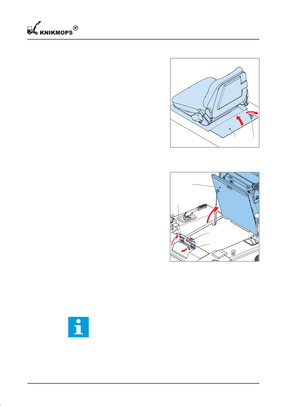
Opening the engine compartment: type 1 (KM80 to KM100)
AB
D
B
A
C
1. Align the lever (A) with the machine.
2. Open the cover, including the driver's
seat (B).
Opening the engine compartment: type 2 (KM120)
Maintenance
1. Align the lever (A) with the machine.
2. Open the cover (B).
3. Pull the lever (C) and open the cover,
including the driver's seat (D).
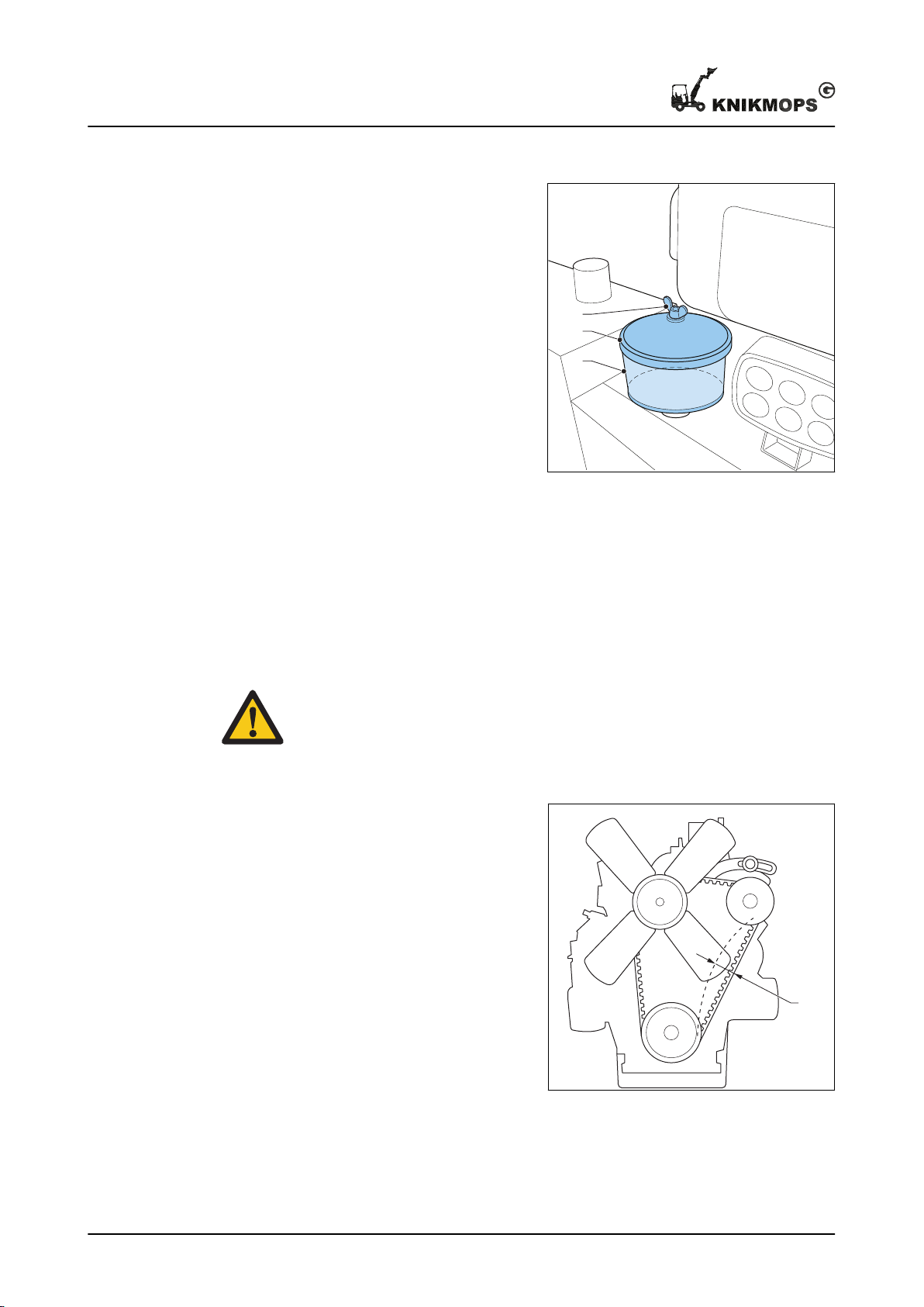
5.6 Clean the pre-filter
The pre-filter is at the back of the machine and is used to filter very coarse dust from the
air before it goes to the air filter.
Before you begin
Note: The pre-filter is not present on all types of machine.
11 - 002 - 30.08.2018 35
Page 36
C
B
A
A
Maintenance
Procedure
1. Loosen the wing nut (A) on the
cover.
2. Remove these parts:
• Wing nut
• Cover (B)
• Filter housing (C)
3. Clean the filter housing. This can be
done in various ways:
• With compressed air.
• With water. Then make sure that
the filter housing is dry again.
4. Fit these parts:
• Filter housing
• Cover
• Wing nut
5. Tighten the wing nut.
5.7 Check the fan belt tension.
Before you begin
Warning:
• Switch off the engine. Check that the engine really is off.
• Make sure the engine has cooled down sufficiently before carrying out this
procedure.
Procedure
1. Open the engine compartment. See
section
2. Push the belt (A) with your thumb, at
the largest span. The belt must have
a play of between 7 and 9 mm.
3. If the belt can move more or less
than allowed, contact a qualified
service technician.
4. Close and lock the engine
compartment.
5.5
.
36 11 - 002 - 30.08.2018
Page 37
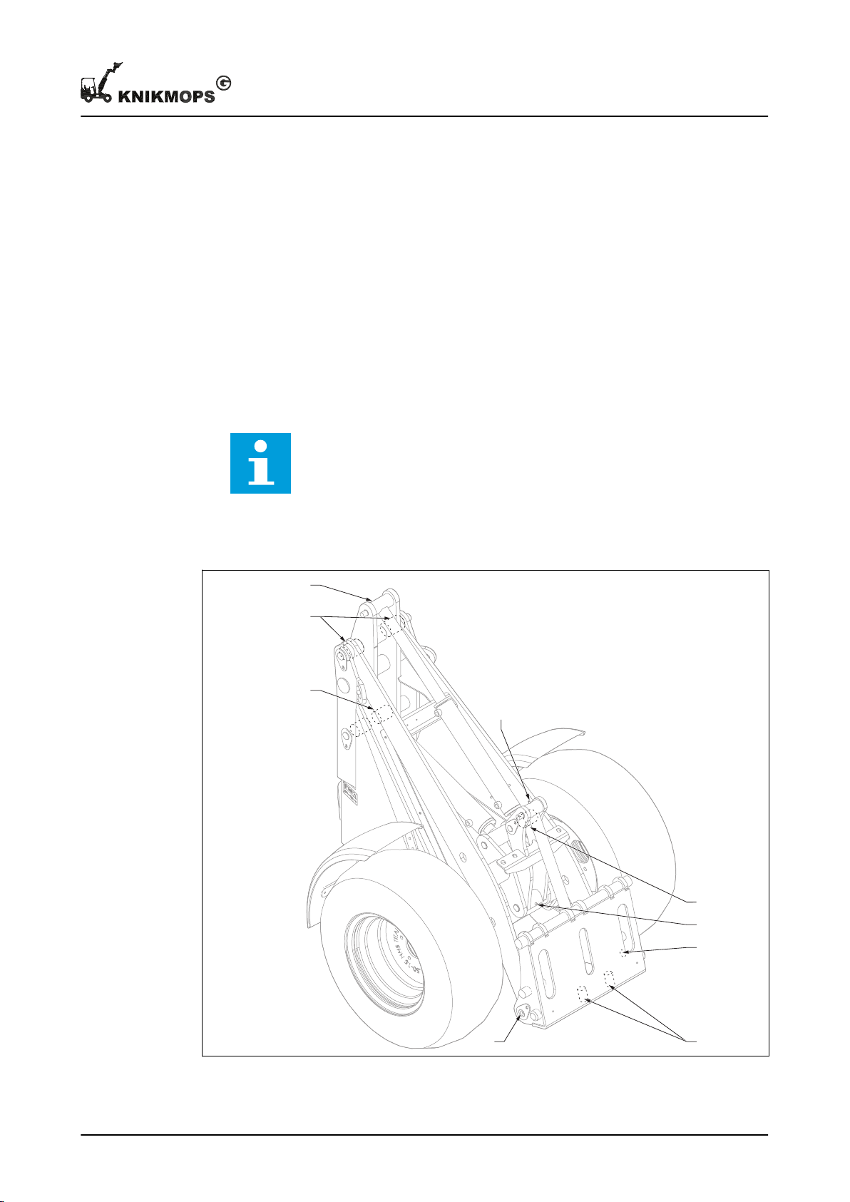
5.8 Checking the parking brake
A
A
A
A
A
B
A
A
A
1. Pull the parking brake fully up.
2. Try to drive the machine forwards and backwards.
3. If the machine moves forwards or backwards, contact a qualified service technician.
5.8.1 Lubricate the hinge points
5.8.2 Procedure: lubrication via grease nipples
1. Add grease through the grease nipples (see following sections) until grease comes
out of the bearing. Use a grease gun. For the correct type of grease, see section
2. Remove excess grease.
Note: It is possible that grease is still released for a longer period of time
after lubrication. This is a normal phenomenon.
Maintenance
7.1
.
5.8.3 Grease nipples standard versions
A Grease nipple B Grease nipple (only with vertical
11 - 002 - 30.08.2018 37
locking pin)
Page 38
A
A
A
A
A
A
A
A
A
A
A
A
A
B
A
B
Maintenance
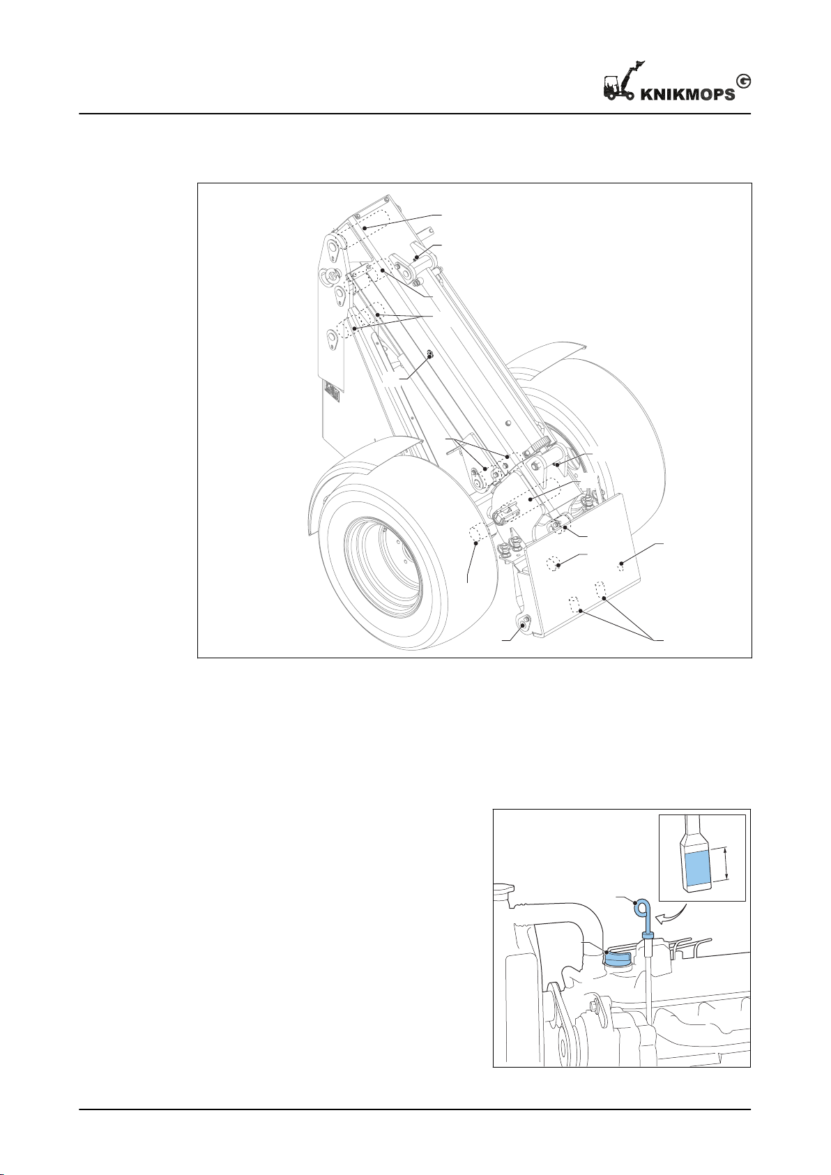
5.8.4 Grease nipples TE versions
A Grease nipple B Grease nipple (only with vertical
5.9 Check/top up the engine oil level
1. Open the engine compartment. See
section
2. Remove the engine oil dipstick (A)
from the holder, clean the engine oil
dipstick and replace it.
3. Remove the engine oil dipstick from
the holder again and check that the
engine oil level is between the MIN
and MAX marks. Then replace the
engine oil dipstick.
4. If the engine oil level is too low:
a) Remove the engine oil cap (B).
b) Fill up the oil tank.
5.5
.
For the correct type of engine oil,
see section
7.1
.
locking pin)
38 11 - 002 - 30.08.2018
Page 39
c) Wait 5 minutes and repeat steps 2 and 3 to check if the oil level is correct.
A
FULL
LOW
A
d) Replace the engine oil cap.
5. Close and lock the engine compartment.
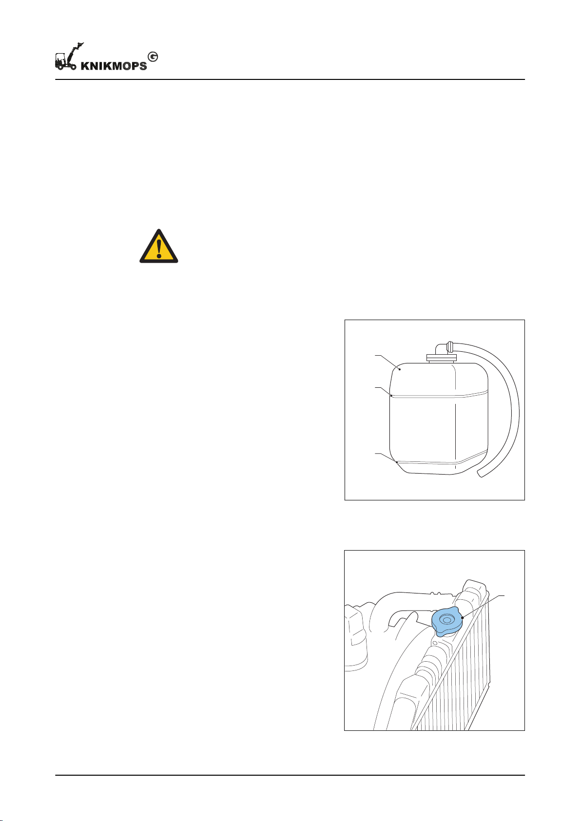
5.10 Check/top up the coolant fluid level
Safety
Warning: Make sure the engine has cooled down sufficiently before carrying
out this procedure. Hot coolant fluid can spray out of the radiator.
Check
1. Open the engine compartment. See
section
2. Check whether the reservoir (A)
contains sufficient coolant fluid. The
fluid level must be between the
"FULL" and "LOW" marks.
3. If the reservoir is not properly filled,
top up the coolant fluid. See the
procedure below.
4. Close and lock the engine
compartment.
5.5
.
Maintenance
Topping up
1. Remove the cap (A) from the
radiator. First unscrew it 1 turn and
allow any overpressure to escape
before you completely remove the
cap.
2. Fill coolant fluid up to the 'FULL'
mark on the reservoir.
For the correct type of coolant fluid,
7.1
see section
11 - 002 - 30.08.2018 39
3. Refit the radiator cap.
4. Close and lock the engine
compartment.
.
Page 40
4
2
3
1
0
D
A
B
C
A
Maintenance
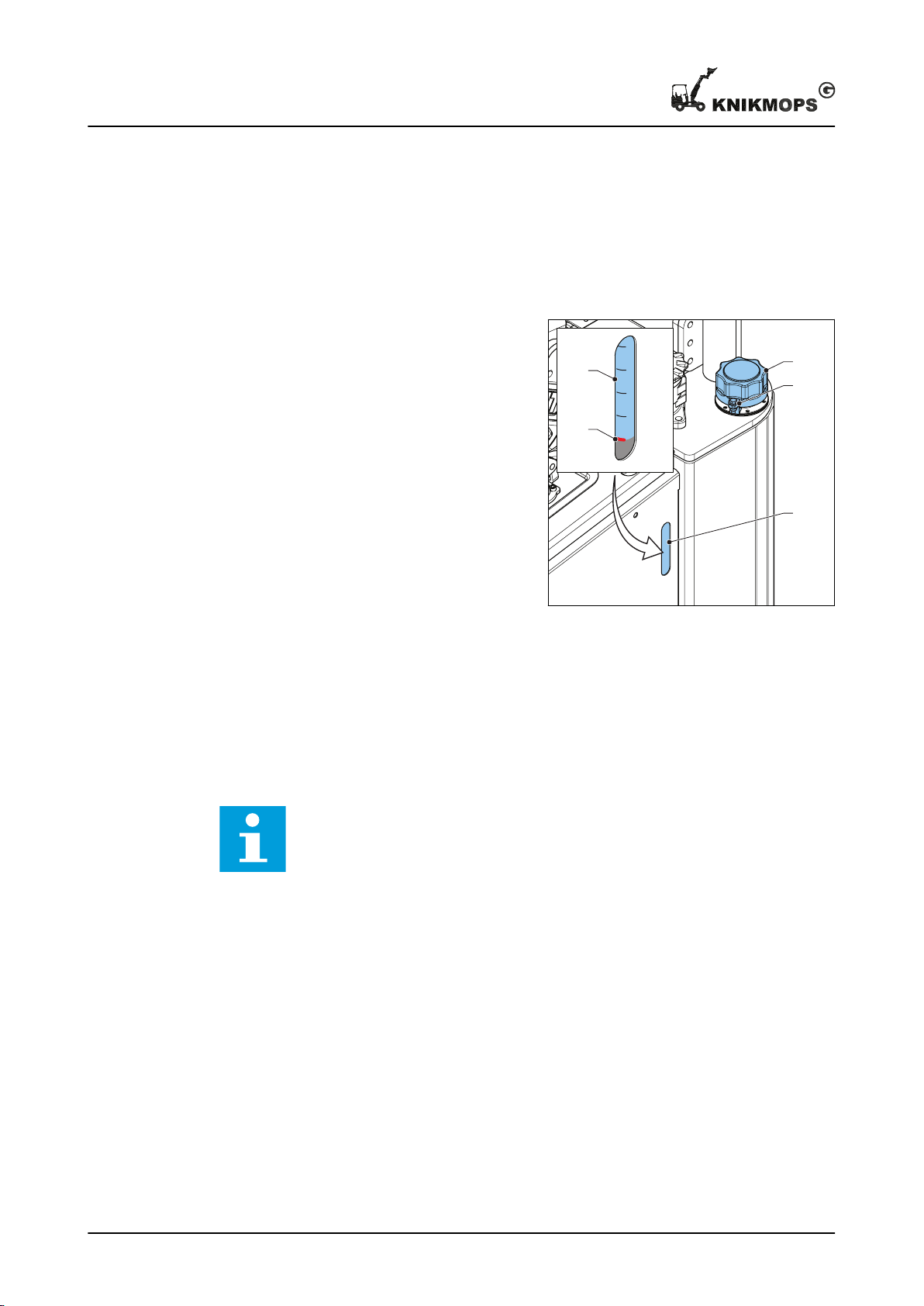
5.11 Check and top up the hydraulic fluid level
Before you begin
Condition: the temperature of the hydraulic fluid must be approximately 20° C.
Procedure
1. Check the liquid level in the sight
glass (A).
The fluid level must be as far as the
bottom red mark (B).
2. If the fluid level is too low:
a) Remove the bolt and the nut (C).
b) Remove the filler cap (D).
c) Fill up the tank.
For the correct type of hydraulic
fluid, see section
d) Refit the filler cap and secure the
filler cap with the bolt and nut.
3. If the fluid level is too high, contact a
qualified service technician.
7.1
.
5.12 Replace the air filter
Spares
• For the correct replacement parts, contact the manufacturer.
Safety
Note: This procedure may only be carried out by a qualified service
technician.
40 11 - 002 - 30.08.2018
Page 41
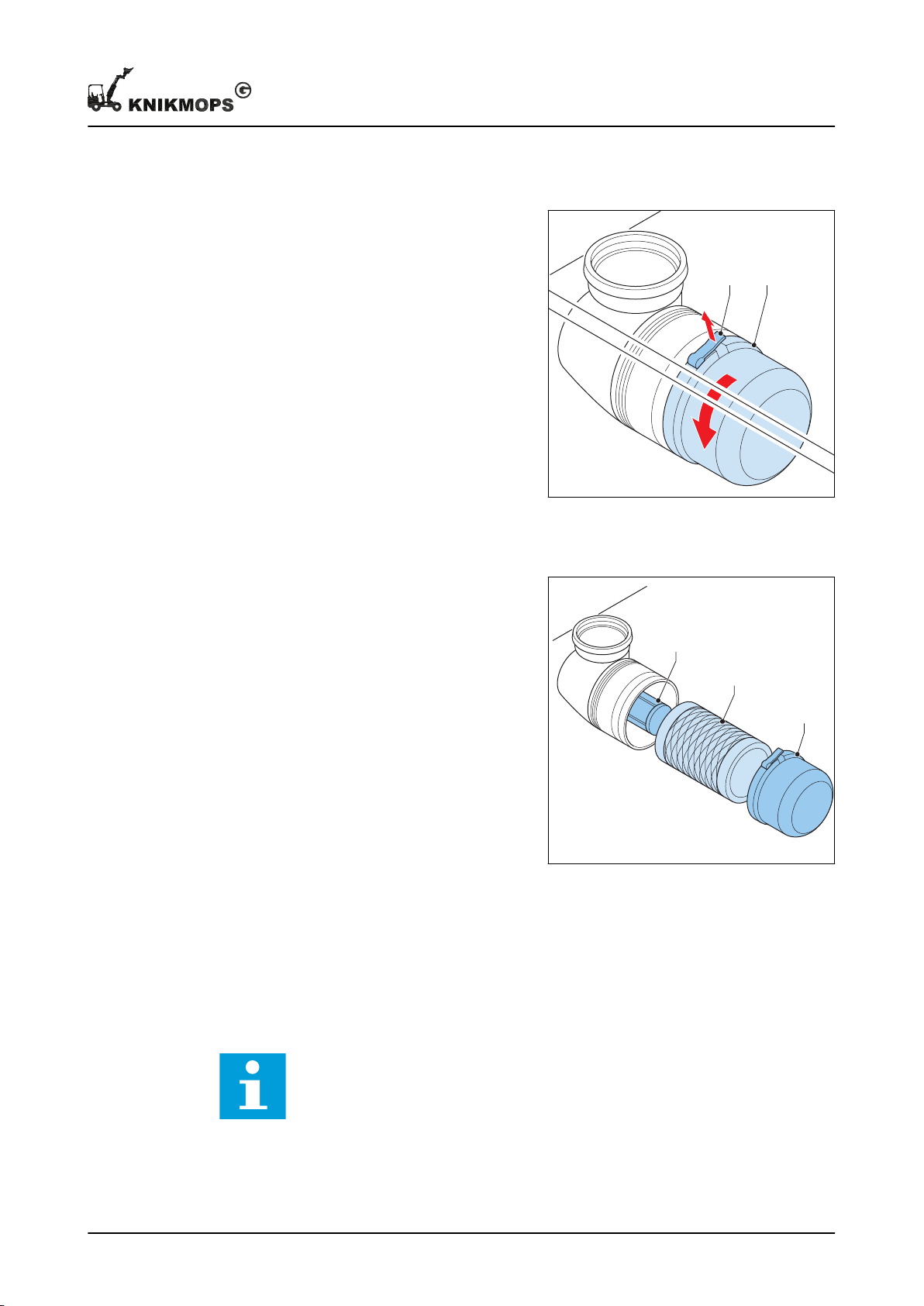
Remove the cover.
A B
C
B
A
Maintenance
1. Open the engine compartment. See section
2. Remove the cover from the air filter.
a) Press the locking tab (A)
upwards.
b) Unscrew the cover (B)
counterclockwise.
Replace the filter.
1. Remove the old air filter (B).
2. Remove the old fine filter (C).
3. Fit the new filters.
4. Replace the cover (A) and turn it
clockwise until the locking tab
engages.
5. Close the engine compartment.
5.5
.
5.13 Replacing the hydraulic fluid filters
Spares
• For the correct replacement parts, contact the manufacturer.
Safety
Note: This procedure may only be carried out by a qualified service
11 - 002 - 30.08.2018 41
technician.
Page 42
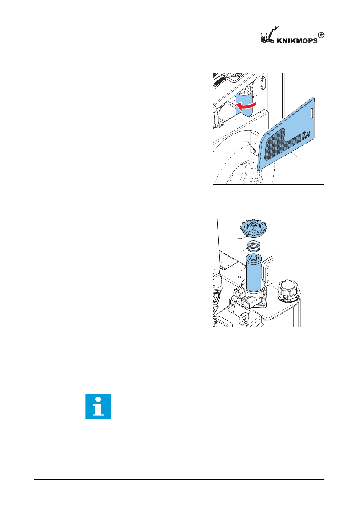
A
C
B
A
B
C
Maintenance
Replace the intake filter.
1. Remove the side panel (A).
2. Place a container under the drain
cap (B).
3. Remove the drain cap.
Hydraulic fluid comes out of the drain
opening.
4. Remove the intake filter (C).
5. Fit the new intake filter.
6. Refit the side panel.
7. Top up the hydraulic fluid. See
section
When the hydraulic fluid needs to be
replaced, use new hydraulic fluid.
5.11
.
Replacing the return filter (only present on certain machine types)
1. Remove these parts:
• Cover (A)
• Coil spring (B)
• Filter element (C)
2. Remove the old filter element.
3. Fit the new filter element.
4. Replace the coil spring and the
cover.
5.13.1 Other lubrication points
5.13.2 Procedure: lubrication via grease nipples
Before you begin
Note: This procedure may only be carried out by a qualified service
technician.
42 11 - 002 - 30.08.2018
Page 43
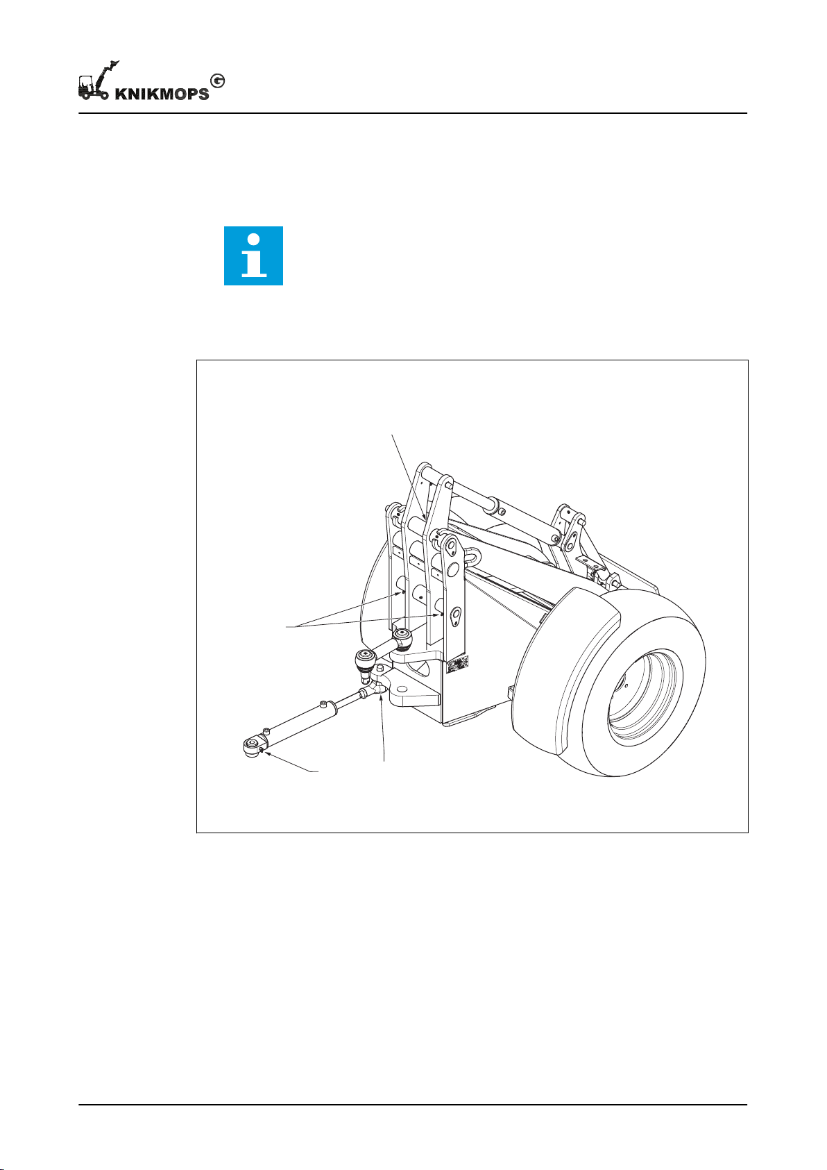
Procedure
A
A
A
A
1. Add grease through the grease nipples (see the next section) until grease comes out
of the bearing. Use a grease gun. Use the right grease. See section
2. Remove excess grease.
Note: It is possible that grease is still released for a longer period of time
after lubrication. This is a normal phenomenon.
5.13.3 Other lubrication points
Maintenance
7.1
.
A Grease nipple
11 - 002 - 30.08.2018 43
Page 44
Resolving problems
6 Resolving problems
6.1 Daily maintenance
1. Try to resolve the problem using the table to find a resolution for the problem.
2. If you cannot find a solution to the problem, contact a qualified service technician or
the manufacturer.
Describe the problem in as much detail as possible and clearly indicate what steps
you have already taken before contacting the qualified service technician or the
manufacturer.
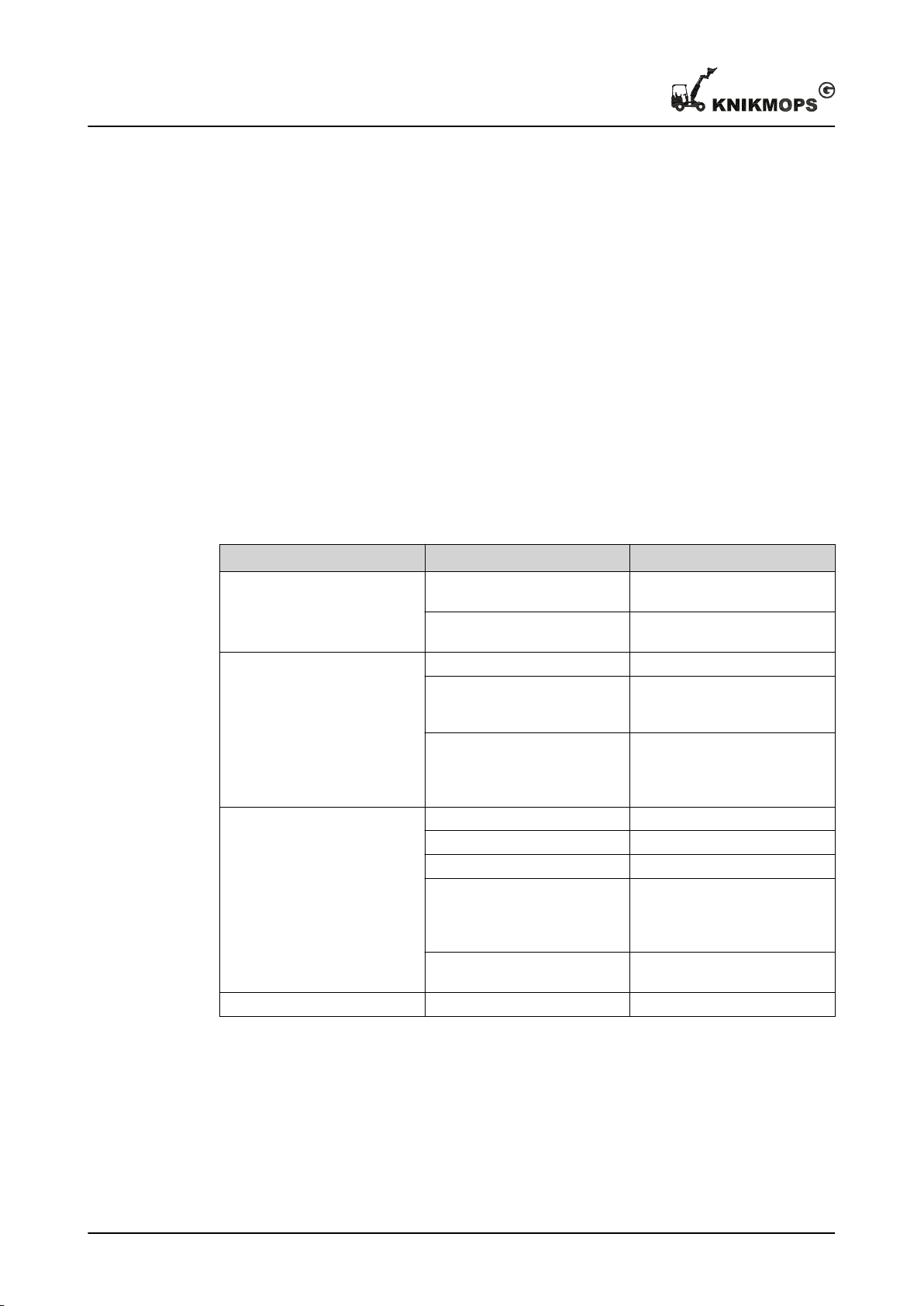
6.2 Troubleshooting table
Problem
The engine does not start and
the start motor does not turn.
The engine does not start but
the start motor does turn.
The engine does not have
enough power.
The machine does not drive. Too little hydraulic fluid. Top up the hydraulic fluid.
Possible cause Possible resolution
The start motor is defective. Contact a qualified service
technician or the manufacturer.
The battery is flat. Contact a qualified service
technician or the manufacturer.
Not enough fuel. Fill up with fuel.
The engine has not pre-heated
long enough.
There is another hydraulic function enabled.
The pre-filter is blocked. Clean the pre-filter.
The fuel filter is blocked. Replace the fuel filter.
The air filter is blocked. Replace the air filter.
There is another hydraulic function enabled.
Wrong fuel used. Contact a qualified service
Hold the ignition key in the "GL"
position longer when you are
starting.
Set all the levers for the auxiliary hydraulic functions to the
neutral position. See section
3.4
.
Set all the levers for the auxiliary hydraulic functions to the
neutral position. See section
3.4
.
technician or the manufacturer.
44 11 - 002 - 30.08.2018
Page 45

Resolving problems
Problem Possible cause Possible resolution
The machine has fallen over -
1. Keep your seat belt on.
2. Stay on the machine.
3. Turn the ignition key to the
'OFF' position to switch off
the engine.
4. Do not start the machine
again. Oil on top of the
piston can damage the engine.
5. Contact a qualified service
technician or the manufacturer.
It is not possible to connect the
hydraulic connection of the interchangeable accessory.
The machine is still under pressure.
The interchangeable accessory
is still under pressure.
1. Turn the ignition key to the
'OFF' position to switch off
the engine.
2. Move the levers for the
auxiliary hydraulic functions back and forth several times to remove the hydraulic pressure.
Remove the hydraulic pressure
from the interchangeable accessory by unscrewing the
hose. Beware of escaping hydraulic fluid.
11 - 002 - 30.08.2018 45
Page 46
Technical data
7 Technical data
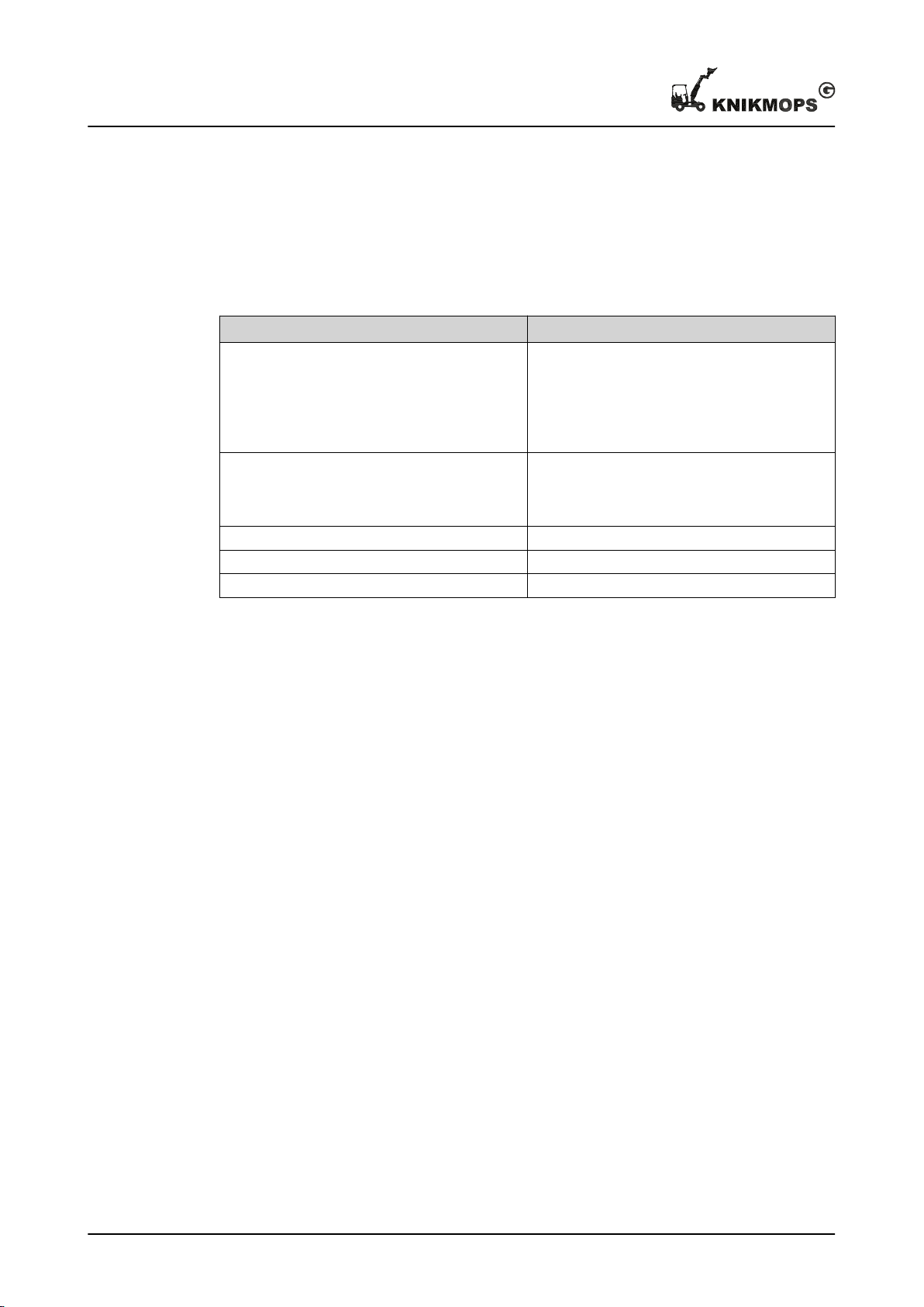
7.1 Consumables
Article Specification
Fuel
Engine oil Oil API class CD grade or higher (for tempera-
Hydraulic fluid AZOLLA ZS 46 (TOTAL)
Coolant COOLELF AUTO SUPRA -26 °C (TOTAL)
Grease General grease classification NLGI 2
Diesel class EN 590. If in doubt, consult the diesel engine user manual.
Check and follow the regulations of the country
where you are located. The use of 'red diesel' is
not allowed in certain countries.
tures higher than -10° C SAE10W-30 or
SAE15W-40, other temperatures: consult the
diesel engine user manual).
46 11 - 002 - 30.08.2018
Page 47
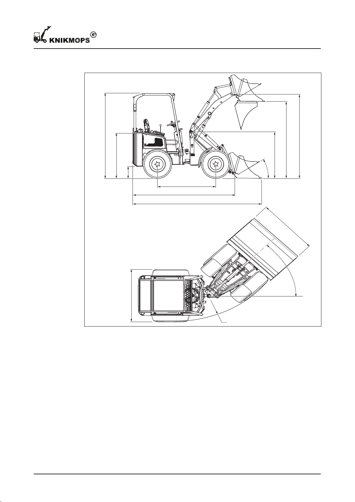
7.2 Reference figure: dimensions
D
G
A
B
C
L
K
M
N
J
I
H
E
F
Technical data
11 - 002 - 30.08.2018 47
A Wheelbase H Roll bar height / ROPS-FOPS height
B Total length without bucket I Seat height
C Total length with bucket J Ground clearance
D Total width K Tipping-in angle from ground surface
E Width L Jib hinge height
F Maximum turning angle M Transfer height
G Outside turning circle N Shovel bucket rotation point, maximum
height
Page 48
1
2
3
Y
X
Technical data
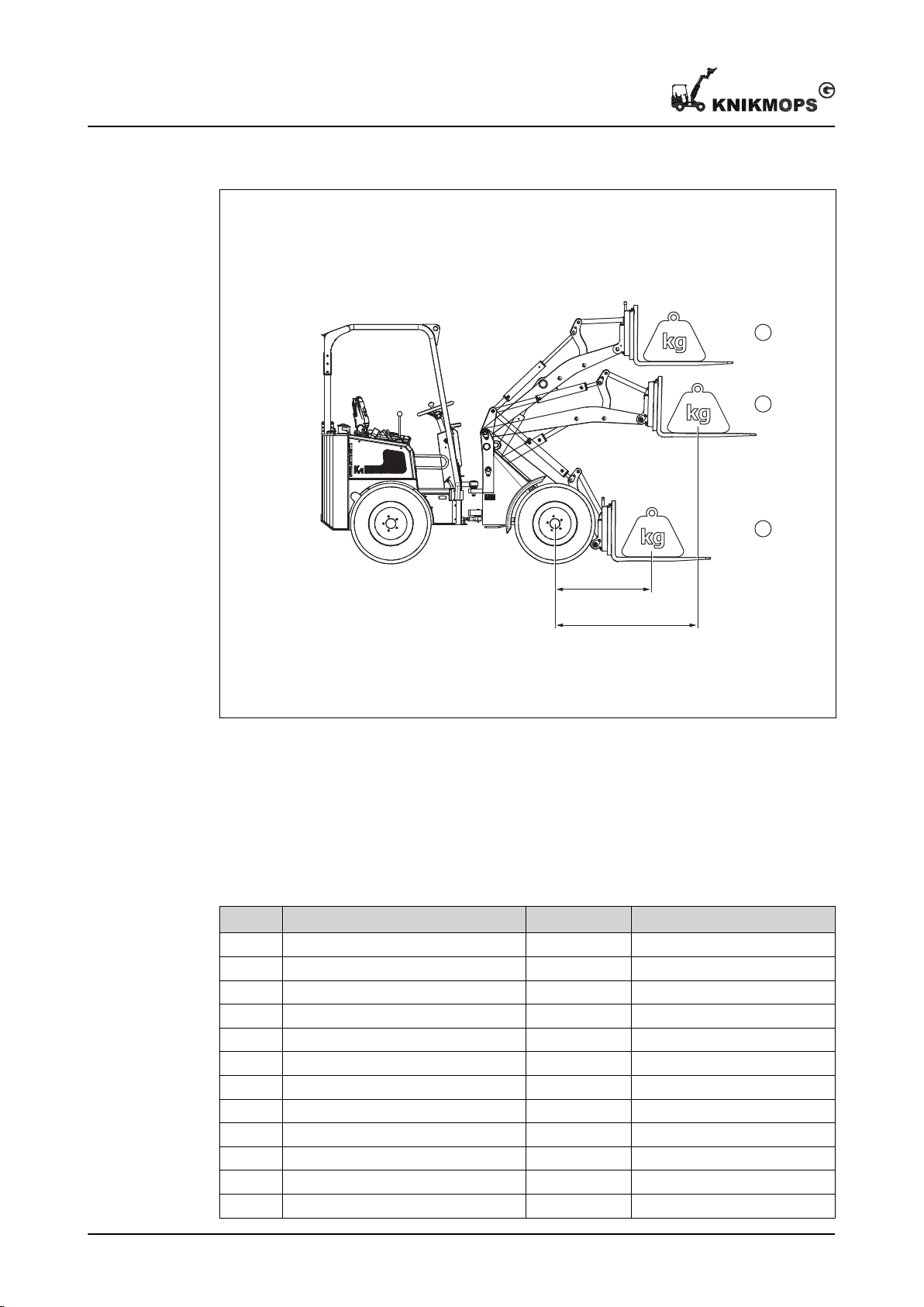
7.3 Reference figure: maximum load
X Fully retracted boom (smallest torque) Y Fully extended boom (greatest torque)
7.4 KM80
Table 1: Dimensions
Position
A Wheelbase [mm / in] 1415 / 55.71
B Total length without bucket [mm / in] 2360 / 92.91
C Total length with bucket [mm / in] 2935 / 115.6
D Total width [mm / in] 750/1020 / 29.53/40.16
E Bucket width [mm / in] 800/100 / 31.5/3.94
F Max. turning angle [°] 50
G Outside turning circle [mm / in] 2120 / 83.46
H Roll bar height / ROPS-FOPS height [mm / in] 2040/2100 / 80.31/ 82.68
I Seat height [mm / in] 1070 / 42.16
J Ground clearance [mm / in] 205 / 8.07
K Tipping-in angle from ground surface [°] 30
L Jib hinge height [mm / in] 1060 / 41.73
Parameter Unit Value
48 11 - 002 - 30.08.2018
Page 49
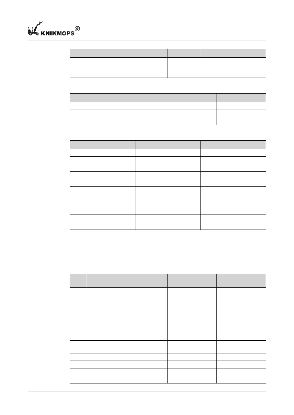
Position Parameter Unit Value
M Transfer height [mm / in] 1715 / 67.52
N Shovel bucket rotation point, maxi-
mum
[mm / in] 1895 / 74.61
Table 2: Maximum load
Position Status
1 (X = 830 mm) Not bent [kg / lbs] 700 / 1543
2 (Y = 1205 mm) Not bent [kg / lbs] 460 / 1014
3 Not bent [kg / lbs] 550 / 1212
Table 3: Technical data
Technical data
Parameter
Fuel tank capacity [l / US gallons] 20 / 5.3
Diesel engine type Kubota D722
Engine power [kW / pk] 13/18
Number of cylinders 3
Work hydraulics flow [l/min / gpm] 28 / 6.2
Hydraulic operating pressure [bar / psi] 180 / 2610
Total weight without exchangeable accessory
Lifting power [kg / lbs] 450 / 992
Breakout force [kg / lbs] 550 / 1220
Speed [km/h / mph] 13 / 8.1
7.5 KM85
Table 4: Dimensions
Position
A Wheelbase [mm / in] 1415 / 55.71
B Total length without bucket [mm / in] 2360 / 92.91
C Total length with bucket [mm / in] 2935 / 115.6
D Total width [mm / in] 750/1020 / 29.53/40.16
E Bucket width [mm / in] 800/100 / 31.5/3.94
F Max. turning angle [°] 50
G Outside turning circle [mm / in] 2120 / 83.46
H Roll bar height / ROPS-FOPS height [mm / in] 2040/2100 / 80.31/
I Seat height [mm / in] 1070 / 42.16
J Ground clearance [mm / in] 205 / 8.07
K Tipping-in angle from ground surface [°] 30
L Jib hinge height [mm / in] 1060 / 41.73
Unit Value
[kg / lbs] 820 / 1810
Parameter Unit Value
82.68
11 - 002 - 30.08.2018 49
Page 50
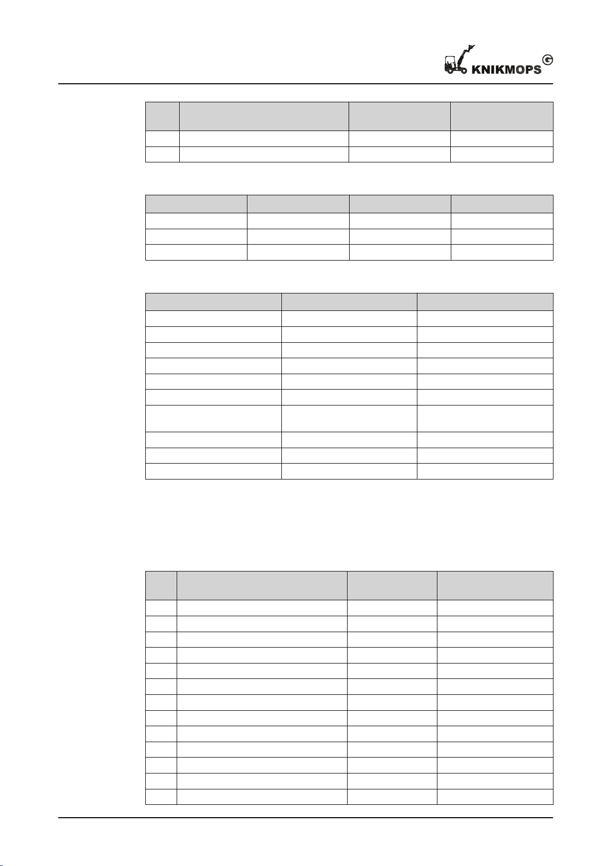
Technical data
Position
M Transfer height [mm / in] 1715 / 67.52
N Shovel bucket rotation point, maximum [mm / in] 1895 / 74.61
Parameter Unit Value
Table 5: Maximum load
Position Status Unit Value
1 (X = 830 mm) Not bent [kg / lbs] 700 / 1543
2 (Y = 1205 mm) Not bent [kg / lbs] 460 / 1014
3 Not bent [kg / lbs] 550 / 1212
Table 6: Technical data
Parameter
Fuel tank capacity [l / US gallons] 20 / 5.3
Diesel engine type Kubota D902
Engine power [kW/pk] 17/23
Number of cylinders 3
Work hydraulics flow [l/min / gpm] 28 / 6.2
Hydraulic operating pressure [bar / psi] 180 / 2610
Total weight without exchangeable accessory
Lifting power [kg / lbs] 450 / 992
Breakout force [kg / lbs] 550 / 1220
Speed [km/h / mph] 13 / 8.1
Unit Value
[kg / lbs] 820 / 1810
7.6 KM100
Table 7: Dimensions
Position
A Wheelbase [mm / in] 1445 / 56.89
B Total length without bucket [mm / in] 2400 / 94.49
C Total length with bucket [mm / in] 2940 / 115.7
D Total width [mm / in] 930/1180 / 36.61/46.46
E Width [mm / in] 960/1250 / 37.8/49.21
F Max. turning angle [°] 45
G Outside turning circle [mm / in] 2380 / 93.7
H Roll bar height / ROPS-FOPS height [mm / in] 2225/2250 / 87.6/88.58
I Seat height [mm / in] 1125 / 44.29
J Ground clearance [mm / in] 245 / 9.65
K Tipping-in angle from ground surface [°] 32
L Jib hinge height [mm / in] 1165 / 45.87
M Transfer height [mm / in] 1775 / 69.88
Parameter Unit Value
50 11 - 002 - 30.08.2018
Page 51
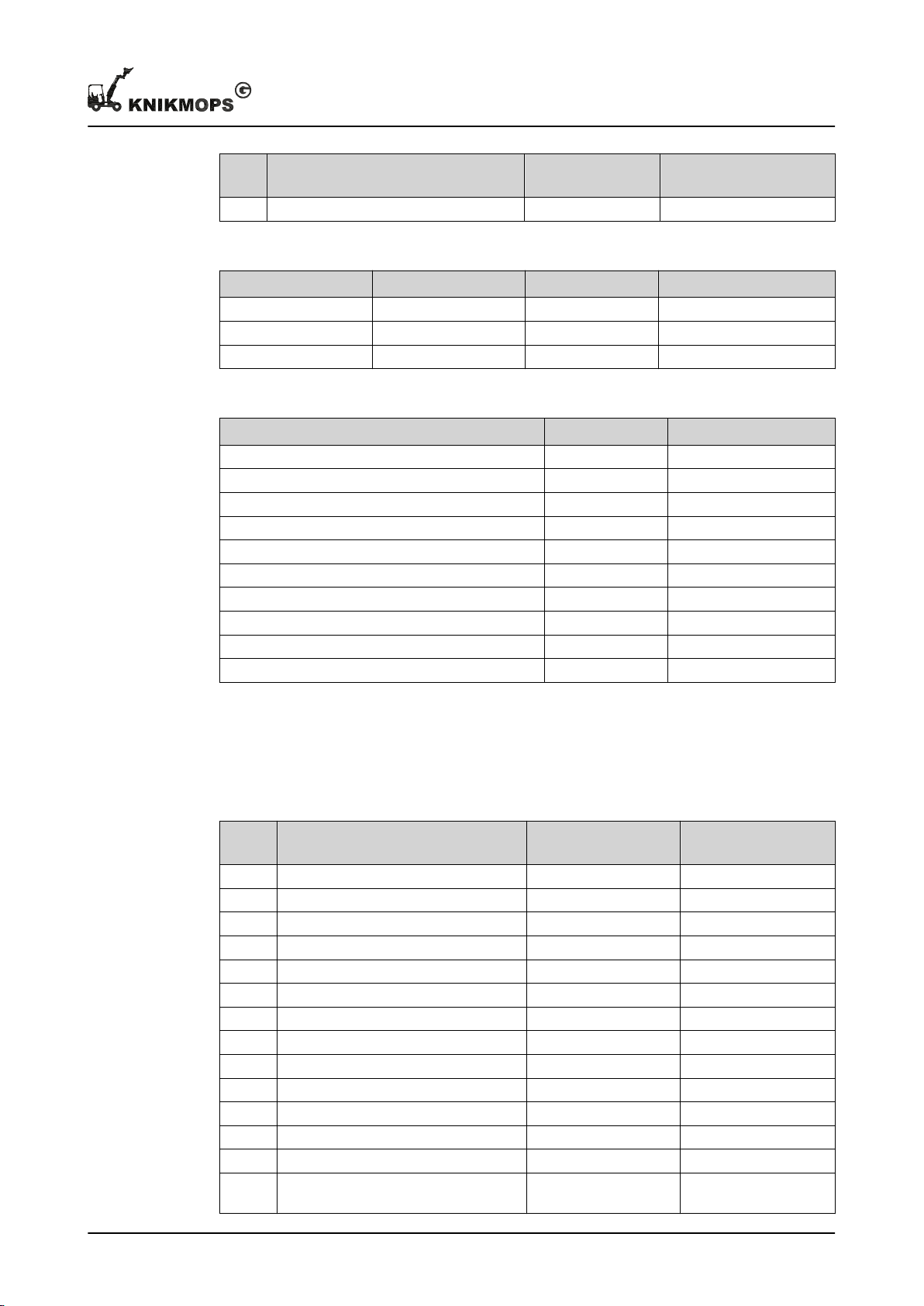
Technical data
Position
N Shovel bucket rotation point, maximum [mm / in] 2030 / 79.92
Parameter Unit Value
Table 8: Maximum load
Position Status Unit Value
1 (X = 820 mm) Not bent [kg / lbs] 910 / 2006
2 (Y = 1235 mm) Not bent [kg / lbs] 730 / 1609
3 Not bent [kg / lbs] 490 / 1080
Table 9: Technical data
Parameter
Fuel tank capacity [l / US gallons] 33 / 8.7
Diesel engine type Kubota D1105
Engine power [kW/pk] 19/25
Number of cylinders 3
Work hydraulics flow [l/min / gpm] 33 / 7.3
Hydraulic operating pressure [bar / psi] 180 / 2610
Total weight without exchangeable accessory [kg / lbs] 950 / 2094
Lifting power [kg / lbs] 650 / 1433
Breakout force [kg / lbs] 750 / 1653
Speed [km/h / mph] 16 / 9.9
Unit Value
7.7 KM100TE
Table 10: Dimensions
Position
A Wheelbase [mm / in] 1530 / 60.24
B Total length without bucket [mm / in] 2610 / 102.8
C Total length with bucket [mm / in] 3250 / 128
D Total width [mm / in] 930/1180 / 36.6/46.5
E Width [mm / in] 960/1250 / 37.8/49.21
F Max. turning angle [°] 45
G Outside turning circle [mm / in] 2380 / 93.7
H Roll bar height / ROPS-FOPS height [mm / in] 2225/2250 / 87.6/88.6
I Seat height [mm / in] 1125 / 44.29
J Ground clearance [mm / in] 245 / 9.65
K Tipping-in angle from ground surface [°] 30
L Jib hinge height [mm / in] 1265 / 49.8
M Transfer height [mm / in] 2230/2790 / 87.8/109.8
N Shovel bucket rotation point, maximum [mm / in] 2405/2965 /
Parameter Unit Value
94.69/116.7
11 - 002 - 30.08.2018 51
Page 52
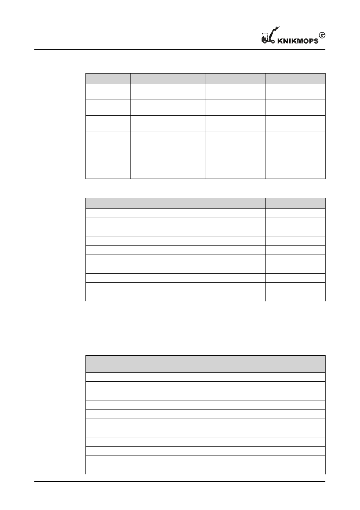
Technical data
Table 11: Maximum load
Position Status Unit Value
1 (X = 995 mm) Not folded, telescopic arm re-
tracted
1 (X = 1800 mm) Not folded, telescopic arm
extended
2 (Y = 1475 mm) Not folded, telescopic arm re-
tracted
2 (Y = 2110 mm) Not folded, telescopic arm
extended
3 Not folded, telescopic arm re-
tracted
Not folded, telescopic arm
extended
[kg / lbs] 800 / 1763
[kg / lbs] 400 / 882
[kg / lbs] 450 / 992
[kg / lbs] 260 / 573
[kg / lbs] 230 / 507
[kg / lbs] 230 / 507
Table 12: Technical data
Parameter
Fuel tank capacity [l / US gallons] 33 / 8.7
Diesel engine type Kubota D1105
Engine power [kW/pk] 19/25
Number of cylinders 3
Work hydraulics flow [l/min / gpm] 28 / 6.2
Hydraulic operating pressure [bar / psi] 180 / 2610
Total weight without exchangeable accessory [kg / lbs] 1280 / 2822
Lifting power [kg / lbs] 675 / 1488
Breakout force [kg / lbs] 775 / 1708
Speed [km/h / mph] 18 / 11
7.8 KM120
Table 13: Dimensions
Position
A Wheelbase [mm / in] 1550 / 61.02
B Total length without bucket [mm / in] 2710 / 106.7
C Total length with bucket [mm / in] 3390 / 133.5
D Total width [mm / in] 950/1250 / 37.4/49.2
E Width [mm / in] 1000/1270 / 39.37/50
F Max. turning angle [°] 47
G Outside turning circle [mm / in] 2400 / 94.49
H Roll bar height / ROPS-FOPS height [mm / in] 2170/2260 / 85.43/88.98
I Seat height [mm / in] 1270 / 50
J Ground clearance [mm / in] 315 / 12.4
K Tipping-in angle from ground surface [°] 30
Unit Value
Parameter Unit Value
52 11 - 002 - 30.08.2018
Page 53
Technical data
Position
L Jib hinge height [mm / in] 1230 / 48.43
M Transfer height [mm / in] 1975 / 77.76
N Shovel bucket rotation point, maxi-
Parameter Unit Value
[mm / in] 2145 / 84.45
mum
Table 14: Maximum load
Position Status Unit Value
1 (X = 1020 mm) Not bent [kg / lbs] 1260 / 2778
2 (Y = 1450 mm) Not bent [kg / lbs] 670 / 1477
3 Not bent [kg / lbs] 740 / 1631
Table 15: Technical data
Parameter
Fuel tank capacity [l / US gallons] 37 / 9.8
Diesel engine type Kubota D1105
Engine power [kW/pk] 19/25
Number of cylinders 3
Work hydraulics flow [l/min / gpm] 33 / 7.3
Hydraulic operating pressure [bar / psi] 180 / 2610
Total weight without exchangeable accessory
Lifting power [kg / lbs] 875 / 1929
Breakout force [kg / lbs] 975 / 2150
Speed [km/h / mph] 18 / 11
Unit Value
[kg / lbs] 1300 / 2866
7.9 KM120TE
Table 16: Dimensions
Position
A Wheelbase [mm / in] 1650 / 64.96
B Total length without bucket [mm / in] 2860 / 112.6
C Total length with bucket [mm / in] 3540 / 139.4
D Total width [mm / in] 950/1250 / 37.4/49.2
E Width [mm / in] 1000/1270 / 39.37/50
F Max. turning angle [°] 47
G Outside turning circle [mm / in] 2400 / 94.5
H Roll bar height / ROPS-FOPS height [mm / in] 2170/2260 / 85.43/88.98
I Seat height [mm / in] 1270 / 50
J Ground clearance [mm / in] 315 / 12.4
K Tipping-in angle from ground surface [°] 30
11 - 002 - 30.08.2018 53
Parameter Unit Value
Page 54
Technical data
Position
L Jib hinge height [mm / in] 1320 / 51.97
M Transfer height [mm / in] 2420/3030 / 95.28/119.3
N Shovel bucket rotation point, maximum [mm / in] 2590/3200 / 102/126
Parameter Unit Value
Table 17: Maximum load
Position Status Unit Value
1 (X = 1060
mm)
1 (X = 1925
mm)
2 (Y = 1550
mm)
2 (Y = 2250
mm)
3 Not folded, telescopic arm re-
Not folded, telescopic arm retracted
Not folded, telescopic arm extended
Not folded, telescopic arm retracted
Not folded, telescopic arm extended
tracted
Not folded, telescopic arm extended
[kg / lbs] 1100 / 2425
[kg / lbs] 640 / 1411
[kg / lbs] 840 / 1852
[kg / lbs] 500 / 1102
[kg / lbs] 520 / 1146
[kg / lbs] 380 / 838
Table 18: Technical data
Parameter
Fuel tank capacity [l / US gallons] 37 / 9.8
Diesel engine type Kubota D1105
Engine power [kW/pk] 19/25
Number of cylinders 3
Work hydraulics flow [l/min / gpm] 33 / 7.3
Hydraulic operating pressure [bar / psi] 180 / 2610
Total weight without exchangeable accessory
Lifting power [kg / lbs] 850 / 1874
Breakout force [kg / lbs] 950 / 2094
Speed [km/h / mph] 18 / 11
Unit Value
[kg / lbs] 1475 / 3252
54 11 - 002 - 30.08.2018
 Loading...