

Page 1
(303IO) MODEL SM24100 SWIMMING MACHINE ENGLISH 7.5” X 10.3” PANTONE 295U 08/30/2018
English
303A
IMPORTANT
SAFETY RULES
Please read, understand, and follow all
instructions carefully before installing
and using this product. Keep for future
reference.
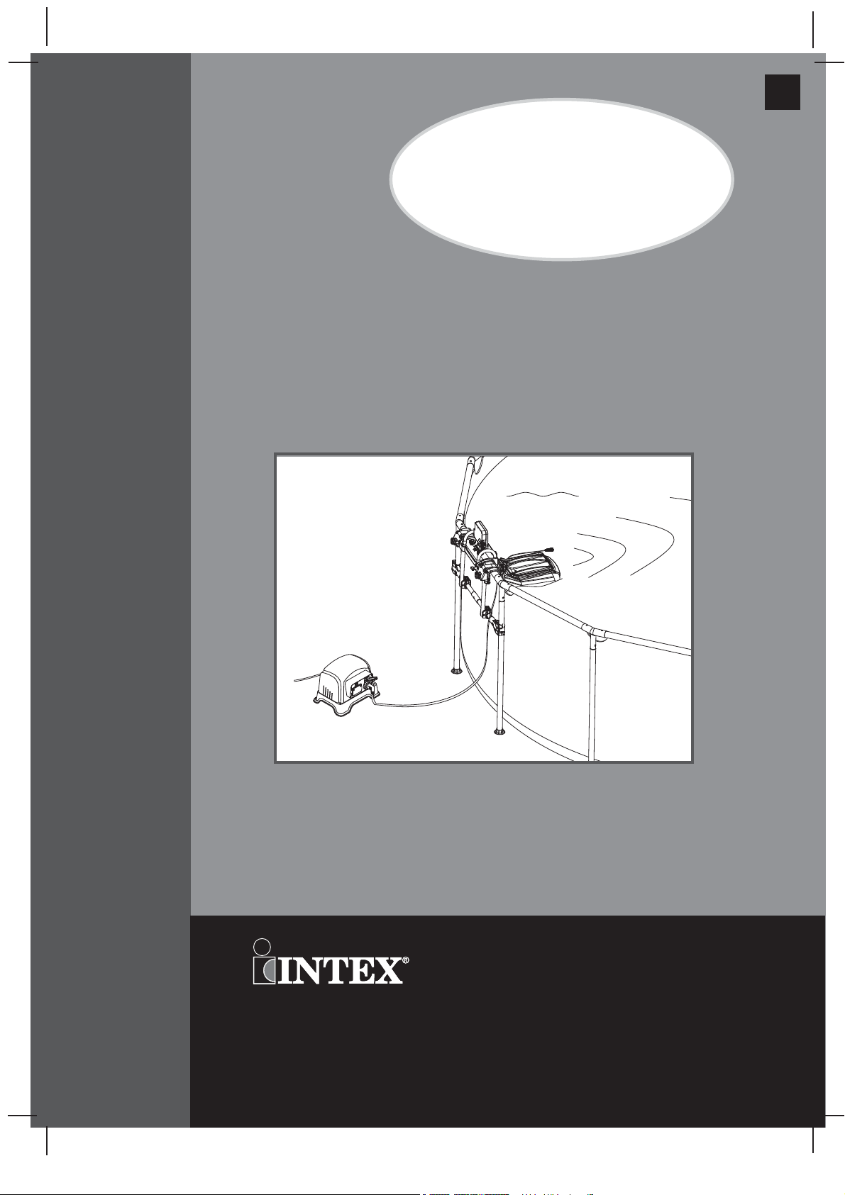
Hydro Flow Swim Trainer™
Model SM24100
230-240V AC / 50Hz
For illustrative purposes only. Pool not included.
Don’t forget to try these other fine Intex products: pools, pool
accessories, inflatable pools and in-home toys, airbeds and boats
available at fine retailers or visit our website.
Due to a policy of continuous product improvement, Intex
reserves the right to change specifications and appearance,
which may result in updates to the instruction manual without
notice.
©2018 Intex Marketing Ltd. - Intex Development Co. Ltd. - Intex Recreation
Corp.
Rechte vorbehalten. Printed in China/Imprimé en Chine/Impreso en China/Gedruckt in China.
®™ Trademarks used in some countries of the world under license from/®™ Marques utilisées dans certains pays sous
OWNER’S MANUAL
licence de/Marcas registradas utilizadas en algunos países del mundo bajo licencia de/Warenzeichen verwendet in einigen
Ländern der Welt in Lizenz von/
Kong & Intex Recreation Corp., P.O. Box 1440, Long Beach, CA 90801
dans l’Union Européenne par/Distribuido en la unión Europea por/Vertrieb in der Europäischen Union durch/
B.V., Venneveld 9, 4705 RR Roosendaal – The Netherlands
www.intexcorp.com
All rights reserved/Tous droits réservés/Todos los derechos reservados/Alle
Intex Marketing Ltd. to/à/a/an Intex Development Co. Ltd., G.P.O Box 28829, Hong
• Distributed in the European Union by/Distribué
Intex Trading
303-*A*-R0-1908
Page 2
(303IO) MODEL SM24100 SWIMMING MACHINE ENGLISH 7.5” X 10.3” PANTONE 295U 08/30/2018
TABLE OF CONTENTS
Warnings
Parts Reference
Product Specification
Setup Instructions
Operating Instructions
Maintenance
..................................................................................... 3
..........................................................................
......................................................................
...............................................................................
................................................................
...............................................................
English
4-5
6
6-13
14-15
15
303A
Internal Parts Replacements
Troubleshooting Guide
Limited Warranty
.........................................................................
..............................................................
.....................................................
16-17
18-19
20
SAVE THESE INSTRUCTIONS
Page 2
Page 3

(303IO) MODEL SM24100 SWIMMING MACHINE ENGLISH 7.5” X 10.3” PANTONE 295U 08/30/2018
English
303A
IMPORTANT SAFETY RULES
Read, Understand and Follow All Instructions Carefully Before Installing and Using this Product.
READ AND FOLLOW ALL INSTRUCTIONS
WARNING
• This appliance is not intended for use by persons (including children) with reduced physical, sensory or mental
capabilities, or lack of experience and knowledge, unless they have been given supervision or instruction
concerning use of the appliance by a person responsible for their safety.
• Children should be supervised to ensure that they do not play with the appliance.
• Assembly and disassembly by adults only.
• Cleaning and user maintenance must be performed by adults only who understand the risk of electric shock.
• For domestic pool use only. Not for commercial use.
• Risk of electric shock. If replacement of the plug or cord is needed, use only identical replacement parts.
• Always unplug this product from the electrical outlet before removing, cleaning, servicing or making any
adjustment to the product.
• Risk of electric shock. Connect this product only to a grounding type receptacle protected by a ground-fault circuit
interrupter (GFCI) or residual current device (RCD). Contact a qualified electrician if you cannot verify that the
receptacle is protected by a GFCI/RCD. Use a qualified electrician to install the GFCI/RCD, which has a maximum
rate of 30mA. Do not use a portable residual current device (PRCD).
• Do not bury the electrical cord. Locate the cord where it will not be damaged by lawn mowers, hedge trimmers and
other equipment.
• To reduce the risk of electric shock, replace damaged cord immediately. Use a qualified electrician to replace the
cord.
• To reduce the risk of electric shock, do not use extension cords, timers, plug adaptors or converter plugs to
connect unit to electric supply; provide a properly located outlet.
• The appliance is only to be used with the provided transformer.
• Do not attempt to plug in or unplug this product while standing in water or when your hands are wet.
• Position the transformer away from the pool, so as to prevent children from climbing on it and accessing the pool.
• Keep this transformer more than 2m away from the pool.
• Keep the plug of this transformer more than 3.5m away from the pool.
• Pool covers must be completely removed before using this product.
• People using medications and/or having an adverse medical history should consult a physician before
using this product.
• Do not use drugs or alcohol before or during the use of this product.
• Do not use this product when it is snowing, raining, thundering or lightning.
• Do not use this product immediately following strenuous exercise.
• Do not sit, straddle, step or exert pressure on the product as injury could occur.
• Never play or swim near the swim trainer vent holes.
• Keep hair away from the swim trainer vent holes. Your hair may be trapped causing permanent injury or
drowning. Wear a swim cap.
• Do not obstruct the swim trainer vent holes.
• This product is intended to be used only for the purposes described in the manual!
FAILURE TO FOLLOW THESE WARNINGS MAY RESULT IN PROPERTY DAMAGE, ELECTRIC SHOCK,
ENTANGLEMENT OR OTHER SERIOUS INJURY OR DEATH.
SAVE THESE INSTRUCTIONS
Page 3
Page 4
(303IO) MODEL SM24100 SWIMMING MACHINE ENGLISH 7.5” X 10.3” PANTONE 295U 08/30/2018
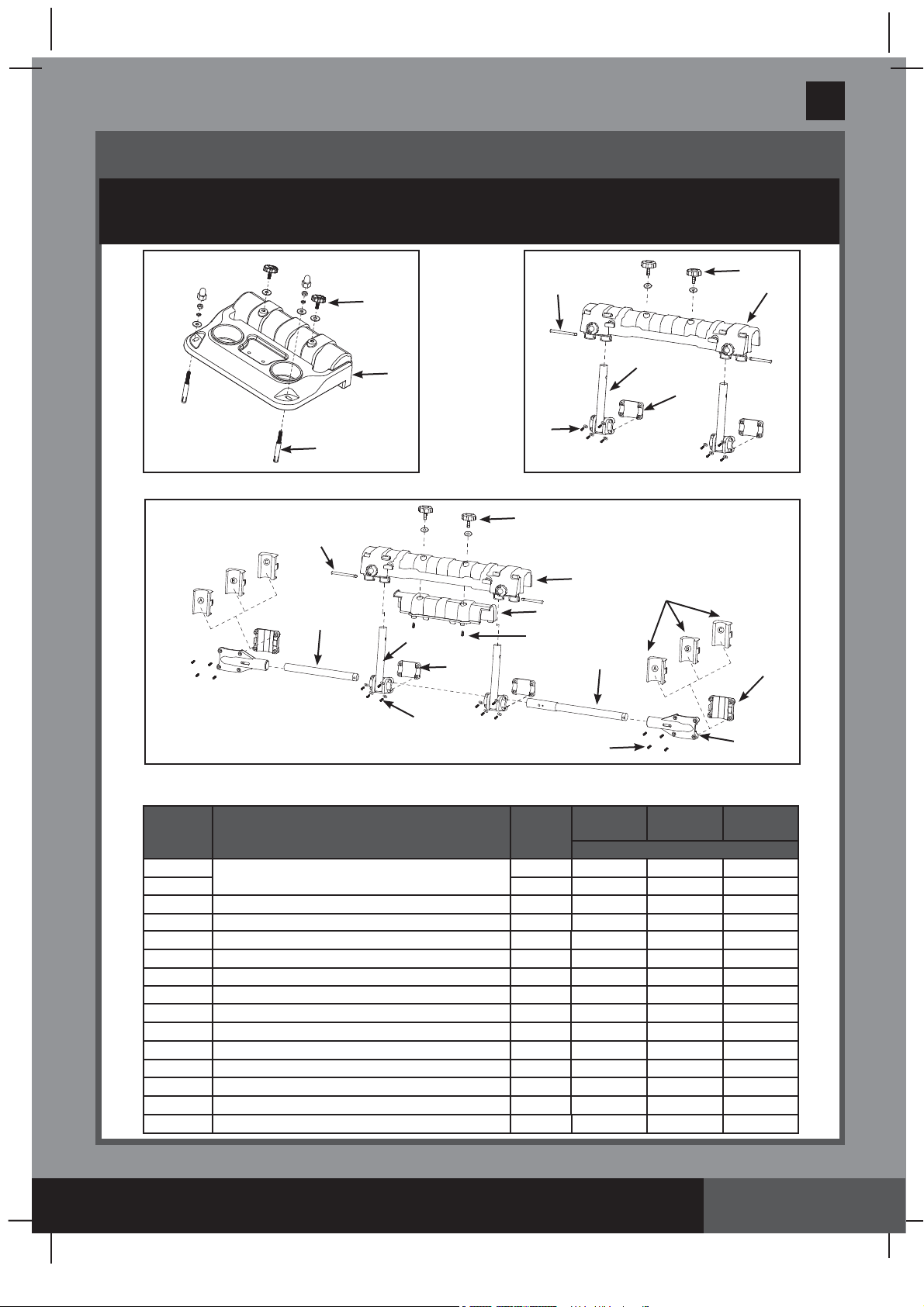
PARTS REFERENCE
Before assembling your product, please take a few minutes to check the contents
and become familiar with all the parts.
9
4
6
7
5
In Ground Pool Mounting Bracket
9
1
8
Intex Rectangular Frame Pool Mounting Bracket
4
English
303A
4
2
2
14
6
7
8
Intex Round Frame Pool Mounting Bracket.
NOTE:
Drawings for illustration purpose only. Actual product may vary. Not to scale.
REF. NO.
1
Mounting Bracket
21
3 Bracket space filler 1
4 Mounting bracket screw 2 12396 12396 12396
5 Anchor screws 2 12407
6 Bracket pole 2
7 Bracket pole fixer 2
8 Screws 16
9 Pin 2
10 Horizontal pipe lugs 2
11 A/B/C gap filler set 2
12 Horizontal pipe fixer 2
13 Horizontal pipe A 1
14 Horizontal pipe B 1
15 screws 4
DESCRIPTION QTY.
3
15
13
8
IGP
POOL
1 12591
-
-
-
-
-
-
--
--
--
--
--
-
11
Intex Rectangular
Frame Pool
SPARE PART NO.
12592 12592
12593 12593
12594 12594
12595 12595
12598 12598
12406 12406
12599 12599
Intex Round Frame
--
--
10
12
Pool
12597
12405
12596
12403
12402
SAVE THESE INSTRUCTIONS
Page 4
Page 5
(303IO) MODEL SM24100 SWIMMING MACHINE ENGLISH 7.5” X 10.3” PANTONE 295U 08/30/2018
18
English
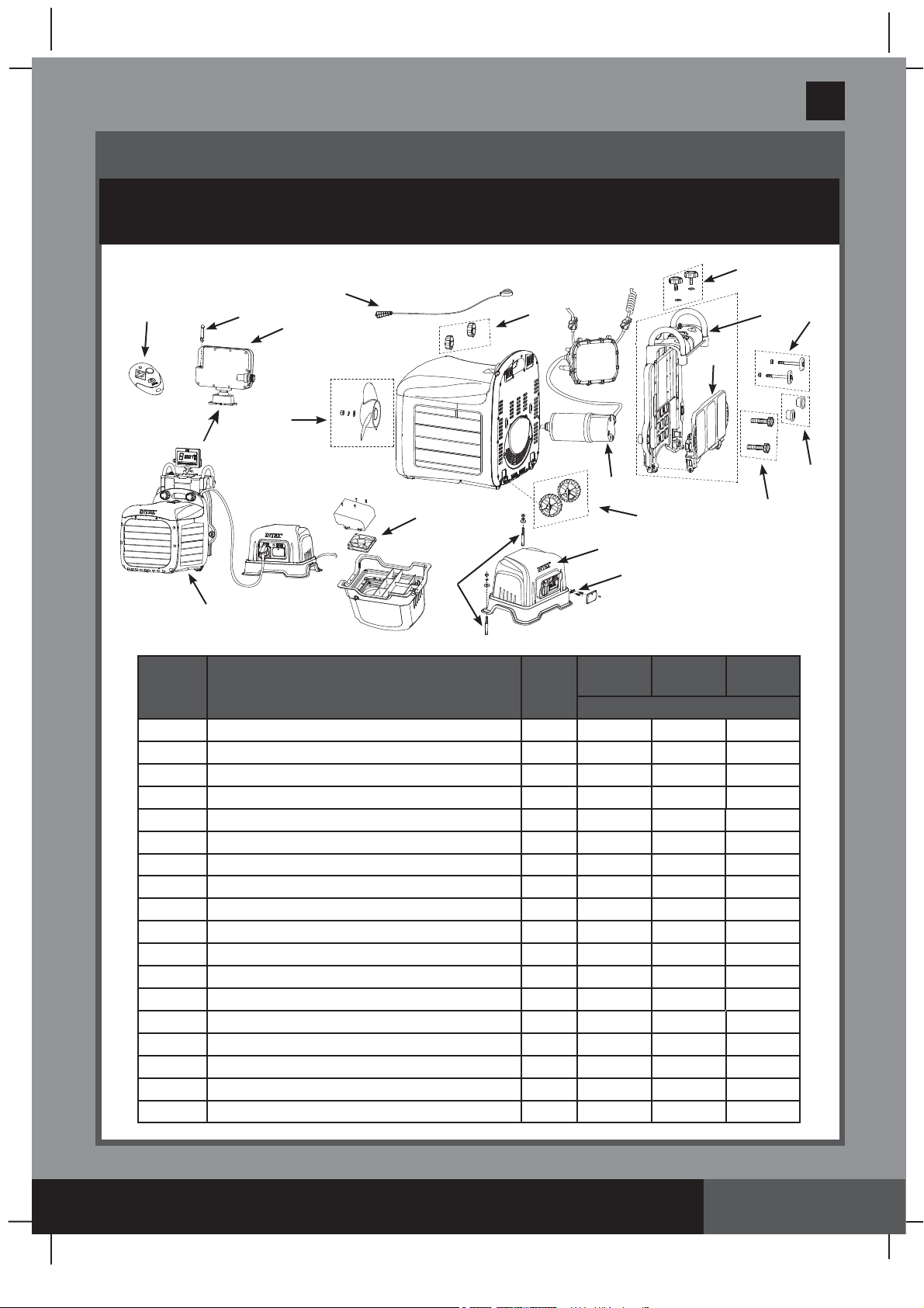
PARTS REFERENCE (continued)
Before assembling your product, please take a few minutes to check the contents
and become familiar with all the parts.
4
19
17
16
31
30
27
20
23
21
26
28
29
25
22
303A
24
33
32
IGP
REF. NO.
16 Display panel 1 12416 12416 12416
17 Display panel antenna 1 12392 12392 12392
18 Remote control 1 12382 12382 12382
19 Emergency stop lanyard 1 12374 12374 12374
20 Clamp knob 2 12395 12395 12395
21 Circuitry box unit 1 12420 12420 12420
22 Support bracket 1 12398 12398 12398
23 Support plate 1 12399 12399 12399
24 Adjustable bolt with nut 2 12397 12397 12397
25 Anchor adjustable bolt 2 12390
26 Wheels kit 2 12389 12389 12389
27 Transformer anchor screws 2 12699 12699 12699
28 Transformer 1 12378 12378 12378
29 Transformer fuse 1 12394 12394 12394
30
31
32 Swim-trainer unit 1 12414 12414 12414
33 Adjustable bolt spacer 2 12600 12600 12600
Transformer fan
Propeller kit
DESCRIPTION QTY.
1 12393 12393 12393
1 12385 12385 12385
POOL
Intex Rectangular
Frame Pool
SPARE PART NO.
-
Intex Round Frame
Pool
12390
SAVE THESE INSTRUCTIONS
Page 5
Page 6
(303IO) MODEL SM24100 SWIMMING MACHINE ENGLISH 7.5” X 10.3” PANTONE 295U 08/30/2018
English
PRODUCT SPECIFICATIONS
Model:
SM24100
Voltage:
Transformer output: +12VDC, 35A
Max Power:
Suitable for:
Pool water temperature range:
This device generates a constant flow of pool water that allows the user to swim
uninterrupted in the swimming pool.
Transformer input: 230-240V AC / 50Hz
880 W
In ground pool or Intex above ground metal frame pools
25ºC - 35ºC
Speed Setting*
m/s
ft/s
12345678
0.66 0.77 0.83 0.94 0.98 1.06 1.16 1.21
2.17 2.53 2.72 3.08 3.22 3.48 3.81 3.97
* Approximate
SETUP INSTRUCTIONS
• Pool must be fi lled with water prior to installation. Two adults required.
• Tools required: one Philip screwdriver, one fl at screwdriver, electric drill,
Ø 13/32" (10mm) concrete drill bit, Ø 11/32" (8.5mm) concrete drill bit and one small
adjustable wrench.
• Pool size requirements:
Pool water depth: 100cm (39 inch) minimum.
Pool length: 4.6m (15') minimum.
Pool width: 2.5m (8.2') minimum.
303A
Transformer Location Requirement
1.
The transformer must be installed on a solid level and vibration-free area.
2.
Provide a location protected from the weather, moisture, rain, splashing water, fl ooding
and freezing temperature.
3.
Provide adequate access, space and lighting for routine maintenance.
4.
The transformer requires free circulation of air for cooling.
Swim-Trainer Unit and Support Bracket Assembly, for all type of pools.
20
25
(1) (2) (3)
NOTE: Make sure the pool wall is able to support a load of 25 kg (55 Lbs) or more
before installation.
22
24
(3.1)
(3.2)
SAVE THESE INSTRUCTIONS
Page 6
Page 7

(303IO) MODEL SM24100 SWIMMING MACHINE ENGLISH 7.5” X 10.3” PANTONE 295U 08/30/2018
SETUP INSTRUCTIONS (continued)
Pool Mounting Bracket Assembly
A: For Intex Rectangular Frame Pools
1. Mounting Bracket Assembly (see fi gures 1.1 to 1.2)
2
1.1
9
6
English
:
303A
1.2
OR
NOTE:
2. Installing the mounting bracket assembly onto a rectangular frame pool wall
(see fi gures 2.1 to 2.3)
Center the swim-trainer unit on the short-end side of the pool.
1 2
X
2.1
SAVE THESE INSTRUCTIONS
Page 7
Page 8

(303IO) MODEL SM24100 SWIMMING MACHINE ENGLISH 7.5” X 10.3” PANTONE 295U 08/30/2018
English
SETUP INSTRUCTIONS (continued)
•
Lock the bracket poles and mounting bracket assembly onto the U-shaped side
support with the bracket pole fi xer
NOTE:
Make sure all the screws are securely tightened and the mounting bracket
(7)
and screws
top surface is level.
7
8
3. Swim-Trainer Unit Assembly (see fi gures 3.1 to 3.2).
• Be sure the swim-trainer unit “support bracket” is closed before installing
the swim-trainer unit onto the mounting bracket assembly
(8), (see fi gure 2.2.).
X X
(see figure 3.1)
303A
2.32.2
.
4
22
MIN
XX
• Extend the support plate, and adjust the depth by loosening the arm collar and
extending the support plate arm until the swim-trainer unit is perfectly
horizontal, retighten to lock it in place.
inside of the pool wall surface.
(see fi gure 3.2)
1
NOTE:
Water level
The support plate must rest against the
.
90 Degree
2
3.1
3.2
SAVE THESE INSTRUCTIONS
Page 8
Page 9

(303IO) MODEL SM24100 SWIMMING MACHINE ENGLISH 7.5” X 10.3” PANTONE 295U 08/30/2018
SETUP INSTRUCTIONS (continued)
B: For Intex Round Frame Pools
1. Mounting Bracket Assembly (see figures 4.1 to 4.5):
• Identify the frame pool pipe shape. For “
For “O” shape pipe see fi gure 4.3 to 4.5.
• For “
(see fi gure 4.2)
• Insert the bracket poles
” shape pipe, remove the bracket space fi ller
. For “O” shape pipe go to next step.
(6)
into the mounting bracket
” shape pipe see fi gure 4.2 to 4.5.
4.1
(3)
(2)
English
from the mounting bracket
inner holes
(see fi gure 4.3)
(2)
303A
.
.
2
• Connect the horizontal pipe A
4.2
3
(13)
with horizontal pipe B
(14)
together, then attach
2
6
the horizontal pipe assembly to the mounting bracket assembly using the bracket
pole fi xer
(7)
and screws
14
(8) (see fi gures 4.4 to 4.5)
13
.
7
4.3
9
4.54.4
12
SAVE THESE INSTRUCTIONS
8
8
Page 9
Page 10

(303IO) MODEL SM24100 SWIMMING MACHINE ENGLISH 7.5” X 10.3” PANTONE 295U 08/30/2018
English
SETUP INSTRUCTIONS (continued)
2. Installing the mounting bracket assembly onto a round frame pool wall
(see figures 5.1 to 5.3):
1
X
• Attach the mounting bracket assembly onto the frame pool vertical legs with the
horizontal pipe lugs
(10)
, screws
pipe include A/B/C gap fi ller
For “
” shape vertical leg pipe, do not include the A/B/C gap fi ller
(8)
, and depending on the shape of the vertical leg
(11) (see fi gure 5.2).
For 38mm diameter vertical leg pipe include “A” gap fi ller.
For 44mm diameter vertical leg pipe include “B” gap fi ller.
For 48mm diameter vertical leg pipe include “C” gap fi ller.
NOTE:
Make sure all the screws are securely tightened and the mounting bracket top
surface is level.
5.2
2
(11).
303A
5.1
5.3
11
10
8
3. Swim-Trainer Unit Assembly (see figures 5.4 to 5.5)
.
X X
• Be sure the swim-trainer unit “support bracket” is closed before installing
the swim-trainer unit onto the mounting bracket assembly
MIN
XX
(see figure 5.4)
4
.
5.4
22
SAVE THESE INSTRUCTIONS
Page 10
Page 11

(303IO) MODEL SM24100 SWIMMING MACHINE ENGLISH 7.5” X 10.3” PANTONE 295U 08/30/2018
SETUP INSTRUCTIONS (continued)
• Adjust the nut on the swimming machine
until the support plate is against the pool
wall and the swim-trainer unit is perfectly
horizontal
C: For In Ground Pools
1. Mounting Bracket Assembly (see
figures 6.1 to 6.3):
• Make sure the top surface of the pool
edge is stable, flat and level.
• Pay attention to the electrical, gas and
water lines when drilling the holes.
• All screws provided must be used.
• Drill two holes [Ø10mm (13/32”)] on the
center of the short-end side of the pool
edge where the mounting bracket will be
installed. Insert the in ground pool screws
(5)
into the holes, and make sure the
screws are fully inserted
to 6.2)
(see figure 5.5).
(see figures 6.1
.
Ajustable nut
for adjusting the
distance
5
Ø10mm(0.4”)
45mm(1.75”)
215mm(8.5”)
332mm(13”)
MAX 40mm(1
English
Water level
.5”)
Water level
90
Degree
303A
5.5
6.1
6.2
100~250mm(4~10”)
• Place the in ground pool mounting bracket
(1)
over the installed bolts
(5)
, tighten
the nuts securely over the bolts and then
install a bolt cap over each nut to prevent
injury
SAVE THESE INSTRUCTIONS
(see figure 6.3)
.
6.3
1
5
Page 11
Page 12

(303IO) MODEL SM24100 SWIMMING MACHINE ENGLISH 7.5” X 10.3” PANTONE 295U 08/30/2018
English
SETUP INSTRUCTIONS (continued)
2. Swim-Trainer Unit Assembly (see fi gures 6.4 to 6.5).
• Be sure the swim-trainer unit “support bracket” is closed before installing the
swim-trainer unit onto the mounting bracket assembly
Max
X X
• Adjust the support nuts on the swim trainer unit until the swim-trainer unit
is horizontal with the water surface
(see figure 6.5)
.
(see fi gure 6.4)
.
4
Water level
303A
6.4
22
6.5
Swim-Trainer Unit height adjustment
and display panel assembly, for all
types of pools
1.
The swim-trainer unit must be submerged
in water with only the top surface of the
housing exposed. Lock the nuts in place
after the height of the swim-trainer unit
is adjusted
2.
Attach the display panel
(see figure 7)
.
(16)
onto the
swim-trainer unit mounting bracket.
Connect the display cable plug to the
display panel receptacle. Tighten up the
display cable collar nut
(see figure 8)
by
hand. Make sure the display cable plug is
firmly attached and the collar nut is
securely tightened.
3.
Place the flat magnetic end of the
emergency stop lanyard
swim-trainer unit
(32)
to activate the unit
IMPORTANT:
During an emergency
(19)
on the
housing in order
(see figure 8)
.
situation, pull the emergency stop
lanyard handle, the unit will stop and
the display panel will go blank.
7
Water level
8
16
19
32
SAVE THESE INSTRUCTIONS
Page 12
Page 13

(303IO) MODEL SM24100 SWIMMING MACHINE ENGLISH 7.5” X 10.3” PANTONE 295U 08/30/2018
SETUP INSTRUCTIONS (continued)
Connecting the swim-trainer unit to the
transformer (see fi gures 9.1 to 9.2)
1.
Be sure the transformer
(2)
switch is OFF,
connect the transformer cable to a
grounded electrical outlet.
Ensure the voltage and electrical rating
indicated on the transformer corresponds
to the local mains voltage before you
connect the unit.
2.
Transformer must be fi xed to a solid,
level ground or base with the transformer
anchor screws
(27)
. Hole size:
Ø 8.5mm x 30mm (Ø 11/32" x 1.2").
Connect the swim-trainer unit power cable
plug into the transformer power receptacle.
Be sure the plug collar is securely tightened
(see fi gure 9.1 to 9.2)
.
.
303A
9.1
Fuse Box
9.2
Power
receptacle
English
ON/OFF Switch
3.
Position the transformer 2m or more away
from the pool, so as to prevent children from
climbing on it and accessing the pool.
4.
Test the GFCI or RCD before use:
27
a) Press the “RESET” button. The indicator
on the GFCI/RCD should be “ON”.
433mm
8.5mm
b) Press the “TEST” button. The indicator
on the GFCI/RCD should be “OFF”.
c) Press the “RESET” button again to
start using the product.
d) Do not use the product if the test failed. Contact a qualifi ed electrician to inspect the
electrical outlet socket.
5.
Turn the transformer switch ON.
NOTE:
To reactivate the swim-trainer unit after the emergency stop lanyard is pulled,
replace the emergency stop lanyard back into the swim-trainer unit, unplugged and
re-plugged the power cable from the transformer.
SAVE THESE INSTRUCTIONS
Page 13
Page 14

(303IO) MODEL SM24100 SWIMMING MACHINE ENGLISH 7.5” X 10.3” PANTONE 295U 08/30/2018
English
OPERATION INSTRUCTIONS
Display Panel Function
Zone #1 Function
A: On/Off Button
B: Speed Increase Button
C: Speed Decrease Button
D: Speed Setting Display
ABC
A: On/Off Button:
transformer and the transformer turned ON, use this button to active the system.
The LED panel will show the default speed setting once activated.
Zone #2 Function
D
EFGH
I
Once the swim-trainer unit is connected to the
Zone #1 Function
Antenna
303A
B/C: Speed Adjustment Buttons:
NOTE:
D: Speed Setting Display:
The default speed is 3; speed adjustment ranges from 1 to 8.
Once activated the system displays the swim-trainer
Press to increase or decrease the speed setting.
unit speed automatically.
Zone #2 Function
H:
Toggle button between
Timer Mode:
Allows the user to program the duration of the
Timer
“ ”
and
Counter
swimming time (in minutes). Once the time is reached,
the machine will stop. Maximum setting is 90 minutes.
E:
Timer Increase Button
F:
Timer Decrease
G:
Timer Review/Confi rm Button
I:
Timer LED Display
Counter Mode:
Tracks the duration (in minutes) or calorie
(in kcal) or distance (in kilometer or mile) of the swim.
E/F:
Counter unit toggle button (minute / kcal
/ kilometer / mile)
G:
Counter On/Pause Button. Press for 2 sec
to reset the counter.
I:
Counter LED Display
“ ”
Mode.
EF G
I
H
I
SAVE THESE INSTRUCTIONS
EFG
H
Page 14
Page 15

(303IO) MODEL SM24100 SWIMMING MACHINE ENGLISH 7.5” X 10.3” PANTONE 295U 08/30/2018
OPERATION INSTRUCTIONS (continued)
Remote Control:
1.
Remove the insulation material under the battery.
Battery type (included): CR2032. Be sure the battery
cover is securely attached.
2.
Place the remote control in a reachable location (on top
of the horizontal pool frame). The back of the remote
control is magnetized.
English
Emergency Cut off Button
303A
Note:
In an emergency situation, simply press the “emergency cut off” button to shut off the
system completely, the indicator light inside the remote control housing will light up and the
display panel will indicate “C”.
MAINTENANCE
• Check and make sure all screws are securely tightened on a regular basis.
• When not in use, fold the display panel down and cover the pool with a pool cover.
Long Term Storage and Winterization
You must disassemble and store the product indoors when the temperature drops below 0
32OF or when the appliance will not be used for a long period of time.
IMPORTANT:
disassembling and removing the swim-trainer unit from
the mounting bracket assembly (Only for Intex
Rectangular Frame Pools).
1. Turn off the transformer and unplug the power
cable from the electrical outlet.
2. Disconnect the swim-trainer unit power cable from
the transformer.
3. Remove the swim-trainer unit and the mounting
bracket assembly from the pool by reversing
the installation instructions.
4. Clean the swim-trainer unit with a garden hose, and air-dry thoroughly under the sun.
5. Store the unit and accessories in a dry place. The storage’s temperature should be between
O
0
C / 32OF and 40OC (104OF). The original packing can be used for storage.
Close the support bracket before
4
22
O
C /
10
SAVE THESE INSTRUCTIONS
Page 15
Page 16

(303IO) MODEL SM24100 SWIMMING MACHINE ENGLISH 7.5” X 10.3” PANTONE 295U 08/30/2018
English
INTERNAL PARTS REPLACEMENTS
Tools required: one Philip screwdriver, one flat screwdriver and one small adjustable
wrench.
A:
Propeller disassembly
1 2
31
303A
SAVE THESE INSTRUCTIONS
Page 16
Page 17

(303IO) MODEL SM24100 SWIMMING MACHINE ENGLISH 7.5” X 10.3” PANTONE 295U 08/30/2018
English
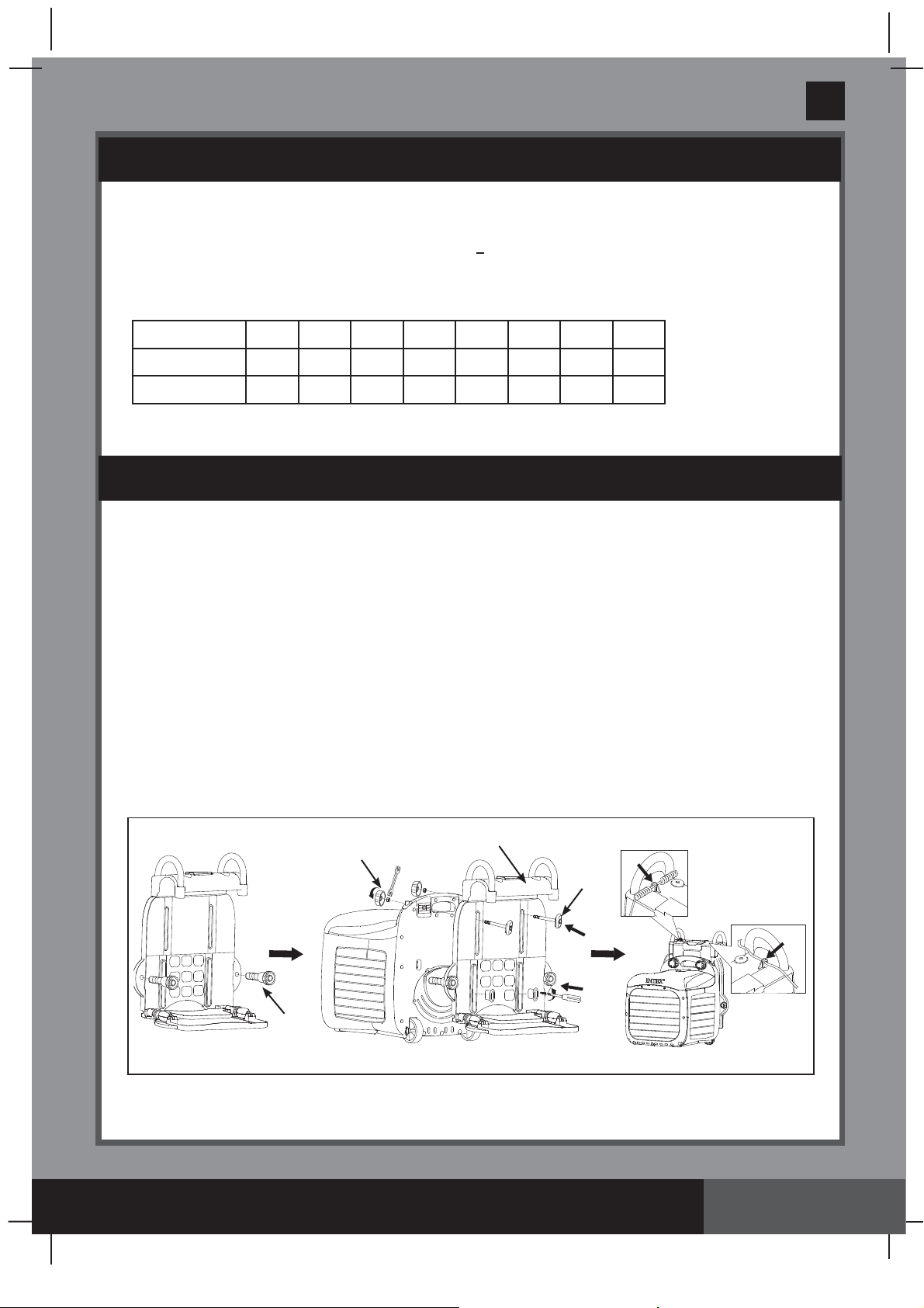
INTERNAL PARTS REPLACEMENTS (continued)
B:
Swim-trainer unit bracket and circuitry box unit disassembly
22
16
3
5
20
22
4
24
33
6
303A
7
SAVE THESE INSTRUCTIONS
Page 17
Page 18

(303IO) MODEL SM24100 SWIMMING MACHINE ENGLISH 7.5” X 10.3” PANTONE 295U 08/30/2018
LED PANEL
CODE
E
C
H
L
TROUBLESHOOTING GUIDE
PROBLEM SOLUTION
●
The maximum operating time
(90 minutes) has fi nished under the
same set mode.
● Low water level.
● Swim-trainer unit is not fully immersed
in the water.
●
Remote control is in an emergency cut
off situation.
●
Household voltage is too low.
●
Household voltage is too heigh.
●
Clogged motor impeller
●
Water temperature is around
35°C (95°F)
English
303A
● It's normal. Turn off and unplug the unit.
Then plug the RCD/GFCI back and
restart all back again.
●
Fill the pool with water up to correct
water level (see pool owner‘s manual).
● Make sure the device is under the water.
●
It‘s normal. Turn off the transformer for
1 minute, then plug in.
●
Check the voltage is within the range
stated on the device housing.
●
Check the voltage is within the range
stated on the device housing
●
Turn off the power, check and clean the
motor impeller
●
Turn off and unplug the unit. When the
water has cooled down, plug the RCD/
GFCI back and restart all over again.
P
●
Operating time is too long
●
Water temperature is around
35°C (95°F)
●
Turn off and unplug the unit, after
30 minutes later plug the RCD/GFCI
back and restart all over again.
●
Turn off and unplug the unit. When the
water has cooled down, plug the RCD/
GFCI back and restart all over again.
SAVE THESE INSTRUCTIONS
Page 18
Page 19

(303IO) MODEL SM24100 SWIMMING MACHINE ENGLISH 7.5” X 10.3” PANTONE 295U 08/30/2018
TROUBLESHOOTING GUIDE (continued)
PROBLEM CAUSE SOLUTION
Mounting bracket
can‘t be assembled
with the in ground
pool
Swim-trainer unit is
not horizontal with
the water surface
No output from the
transformer
●
The ground is not concrete, i.e., it is
asphalt, lawn or earth.
●
The screws are not fully inserted in the
drill holes.
● The support bracket is not opened.
●
Adjust the support nuts on the
swim-trainer unit.
●
Swim-trainer unit will hibernate
if no operating more than 1 hour.
●
The transformer fuse broken.
●
Motor too hot and overload protection is
shut off.
●
Assembly the mounting bracket
on the cement ground.
●
Check and tighten the screws
securely.
●
Open and adjust the support
bracket. See “Setup Instructions”.
●
Adjust the support nuts on the
swim-trainer unit.
●
Turn off the transformer, waiting
2 minutes then turn on agin.
●
Replace the transformer fuse.
●
Let the motor cool down and
restart again.
English
303A
No LED display
Abnormal display /
buttons not working
Too noisy / Jet water
is weak or shaking
●
The transformer is unplugged or off.
●
The transformer is not connected with
swim-trainer unit.
●
Display panel cord is loose.
●
Display panel failure.
●
Emergency stop lanyard is put wrong
place.
●
Display panel cord is loose.
●
Display panel failure.
●
Swim-trainer unit is not fully
immersed in the water.
● The motor impeller is broken.
●
Swim-trainer unit components
not securely connected or in place.
●
Ensure the transformer is
plugged and switched on.
●
Connect the transformer with
swim-trainer unit.
●
Ensure that the display cord is
plugged fi rmly into the cell
housing receptacle.
●
Contact Intex Service Center.
●
Put the emergency stop lanyard
on correct place. See “Setup
Instructions”.
●
Ensure the display cable is
plugged fi rmly into the display
panel receptacle
●
Contact Intex Service Center.
●
Make sure the device is under
.
the water.
●
Turn off and replace the motor
impeller.
●
Check all components, especially
the support bracket. See “Setup
Instructions”.
Remote Control out
●
The battery is on low power.
of control
SAVE THESE INSTRUCTIONS
● Replace the remote control
battery.
See “Operating Installations”.
Page 19
Page 20

(303IO) MODEL SM24100 SWIMMING MACHINE ENGLISH 7.5” X 10.3” PANTONE 295U 08/30/2018
English
303A
LIMITED WARRANTY
Your Hydro Flow Swim Trainer™ has been manufactured using the highest quality
materials and workmanship. All Intex products have been inspected and found free of
defects prior to leaving the factory. This limited warranty applies only to the Hydro Flow Swim
Trainer™ and accessories listed below.
This limited warranty is in addition to, and not a substitute for, your legal rights and remedies.
To the extent that this warranty is inconsistent with any of your legal rights, they take priority.
For example, consumer laws across the European Union provide statutory warranty rights in
addition to the coverage you receive from this limited warranty: for information on EU-wide
consumer laws, please visit the European Consumer Center website at http://ec.europa.eu/
consumers/ecc/contact_en/htm.
The provisions of this limited warranty apply only to the original purchaser and are not
transferable. This limited warranty is valid for the period noted below from the date of the
initial retail purchase. Keep your original sales receipt with this document, as proof of purchase
will be required and must accompany warranty claims or the limited warranty will be invalid.
Hydro Flow Swim Trainer™ Warranty – 2 Years
If you find a manufacturing defect in the Hydro Flow Swim Trainer™ during the warranty
periods noted above, please contact the appropriate Intex Service Center listed in the
separate “Authorized Service Centers” sheet. If the item is returned as directed by the Intex
Service Center, the Service Center will inspect the item and determine the validity of the claim.
If the item is covered by the provisions of the warranty, the item will be repaired or replaced,
with the same or comparable item (at Intex’s choice) at no charge to you.
PARTS LIST
Other than this warranty, and other legal rights in your country, no further warranties are
implied. To the extent possibly in your country, in no event shall Intex be liable to you or any
third party for direct or consequential damages arising out of the use of your Hydro Flow Swim
Trainer™, or Intex or its agents’ and employees’ actions (including the manufacture of the
product). If your country does not allow the exclusion or limitation of incidental or
consequential damages, this limitation or exclusion does not apply to you.
You should note that this limited warranty does not apply in the following circumstances:
• If the Hydro Flow Swim Trainer™ is subject to negligence, abnormal use or application,
accident, improper operation, improper voltage or current contrary to operating instructions,
improper maintenance or storage;
• If the Hydro Flow Swim Trainer™ is subject to damage by circumstances beyond Intex’s
control, including but not limited to, ordinary wear and tear and damage caused by
exposure to fire, flood, freezing, rain, or other external environmental forces;
• To parts and components not sold by Intex; and/or
• To unauthorized alterations, repairs or disassembly to the Hydro Flow Swim Trainer™ by
anyone other than Intex Service Center personnel.
The costs associated with the loss of pool water, chemicals or water damages are not covered
by this warranty. Injury or damage to any property or person is not covered by this warranty.
Read the owner’s manual carefully and follow all instructions regarding proper operation and
maintenance of your Hydro Flow Swim Trainer™. Always inspect your product prior to use.
This limited warranty will be void if use instructions are not followed.
SAVE THESE INSTRUCTIONS
Page 20
 Loading...