

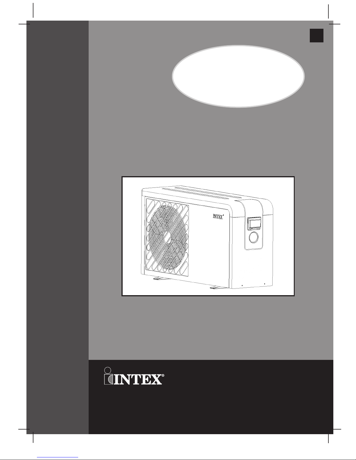
Page 1
307
IO
(307IO) HEAT PUMP ENGLISH 7.5” X 10.3” PANTONE 295U 12/15/2016
English
OWNER’S MANUAL
Heat Pump
Model HP6220
220-240 V~, 50 Hz
IMPORTANT
SAFETY RULES
Read, Understand, and Follow
all Instructions Carefully before
Installing and using this Product.
Don’t forget to try these other fine Intex products: Pools, Pool
Accessories, Inflatable Pools and In-Home Toys, Airbeds and
Boats available at fine retailers or visit our website.
Due to a policy of continuous product improvement, Intex
reserves the right to change specifications and appearance,
which may result in updates to the instruction manual without
notice.
©2016 Intex Marketing Ltd. - Intex Development Co. Ltd. - Intex Trading Ltd.
- Intex Recreation Corp.
All rights reserved/Tous droits réservés/Todos los derechos reservados/Alle
Rechte vorbehalten. Printed in China/Imprimé en Chine/Impreso en China/Gedruckt in China.
®™ Trademarks used in some countries of the world under license from/®™ Marques utilisées dans certains pays sous
licence de/Marcas registradas utilizadas en algunos países del mundo bajo licencia de/Warenzeichen verwendet in einigen
Ländern der Welt in Lizenz von/
Intex Marketing Ltd. to/à/a/an Intex Trading Ltd., Intex Development Co. Ltd., G.P.O
Box 28829, Hong Kong & Intex Recreation Corp., P.O. Box 1440, Long Beach, CA 90801
• Distributed in the European
Union by/Distribué dans l’Union Européenne par/Distribuido en la unión Europea por/Vertrieb in der Europäischen Union
durch/
Intex Trading B.V., Venneveld 9, 4705 RR Roosendaal – The Netherlands
www.intexcorp.com
307-*IO-R0-1712
For illustrative purposes only.
Page 2
(307IO) HEAT PUMP ENGLISH 7.5” X 10.3” PANTONE 295U 12/15/2016
English
307
IO
SAVE THESE INSTRUCTIONS
English
Page 2
Warnings
................................................................................
3-4
Parts Reference
.....................................................................
5-6
Product Specifications
.........................................................
7
Set Up Instructions
...............................................................
8-12
Display Control Panel Operation
.........................................
13
Maintenance
...........................................................................
14
Pool Water Chemistry
...........................................................
14
Heat Pump Caring
.................................................................
15
Troubleshooting
...................................................................
16
Service by Qualified Technicians
.......................................
17-22
Limited Warranty
..................................................................
23
TABLE OF CONTENTS
Page 3
(307IO) HEAT PUMP ENGLISH 7.5” X 10.3” PANTONE 295U 12/15/2016
English
307
IO
SAVE THESE INSTRUCTIONS
English
Page 3
• This appliance shall be installed in accordance with national wiring
regulations.
• To reduce the risk of injury, do not permit children to use this product. Always
supervise children and those with disabilities.
• For domestic swimming pool use only.
• The heat pump must be installed outdoors only.
• Do not bury electrical cord. Locate cord where it will not be damaged by lawn
mowers, hedge trimmers, and other equipment.
• If the supply cord is damaged, it must be replaced by the manufacturer, its
service agent or similarly qualified persons in order to avoid a hazard.
• To reduce the risk of electric shock and fire, do not use extension cords,
timers, plug adaptors or converter plugs to connect unit to electric supply;
provide a properly located outlet.
• Provide a dedicated grounded electrical socket with a rating of 16 Amp or
more. Make sure the plug fit tightly and securely into the electrical socket. If
not sure contact a qualified electrician.
• Assembly and disassembly by adults only.
• Do not attempt to plug in or unplug this product while standing in water or
when your hands are wet.
• Position this product away from pool to prevent a child from climbing on
product to access the pool.
• Children must stay away from this product and electrical cord(s).
• Always unplug this product from the electrical outlet before removing,
cleaning, servicing or making any adjustment to the product.
• Do not switch on if there is no water flowing into the product.
• Do not switch on if there is a possibility that the water in the product is frozen.
• Have a qualified electrician install a grounded electrical outlet, acceptable for
outdoor use and protected from snow and rain, immediately adjacent to the
location where the heater will be used.
• Route the supply cord and locate the heater so as to be protected from
damage by animals.
• Keep this product more than 2m away from the pool.
• Keep the plug of this product more than 3.5m away from the pool.
• Children shall not play with the appliance. Cleaning and user maintenance
must be performed by adults only who understand the risk of electric shock.
IMPORTANT SAFETY RULES
Read, Understand and Follow All Instructions Carefully Before Installing and Using this Product.
READ AND FOLLOW ALL INSTRUCTIONS
WARNING
Page 4
(307IO) HEAT PUMP ENGLISH 7.5” X 10.3” PANTONE 295U 12/15/2016
English
307
IO
SAVE THESE INSTRUCTIONS
English
Page 4
• Check if the voltage indicated on the heat pump corresponds to the local
mains voltage before you connect the unit.
• Do not use the heat pump in combination with other heating system such as
electric or gas heaters.
• If the heat pump is damaged during transportation, it must be replaced, please
contact your service center or similarly qualified persons in order to avoid a
hazard.
• Always make sure the water connections of the heat pump are properly locked
before you start using the machine.
• Never insert objects directly into the fan, as this will damage the heat pump
and void the warranty.
• Make sure the evaporator fins are not damaged.
• This appliance is not intended for use by persons with reduced physical,
sensory or mental capabilities, or lack of experience and knowledge, unless
they have been given supervision or instruction concerning use of the heat
pump by a person responsible for their safety.
• The heat pump doesn’t work at air temperatures below 8°C.
• Disconnect the power cable from the electrical socket when the product will
not be used for an extended period of time.
• Allowing water to freeze inside the unit will damage the heat pump and void
the warranty. Drain the water inside the heat pump during winter time or when
the ambient temperature drops below 0°C.
• Installation and maintenance must be performed by qualified technician.
• Initial system commissioning and decommissioning must only be performed by
specialized technician.
• This product is intended to be used only for the purposes described in the
manual!
FAILURE TO FOLLOW THESE WARNINGS MAY RESULT IN PROPERTY
DAMAGE, ELECTRIC SHOCK, ENTANGLEMENT OR OTHER SERIOUS
INJURY OR DEATH.
These product warnings, instructions and safety rules provided with the product
represent some common risks of water recreation devices and do not cover all
instances of risk and danger. Please use common sense and good judgment
when enjoying any water activity.
WARNING
Page 5
(307IO) HEAT PUMP ENGLISH 7.5” X 10.3” PANTONE 295U 12/15/2016
English
307
IO
SAVE THESE INSTRUCTIONS
English
Page 5
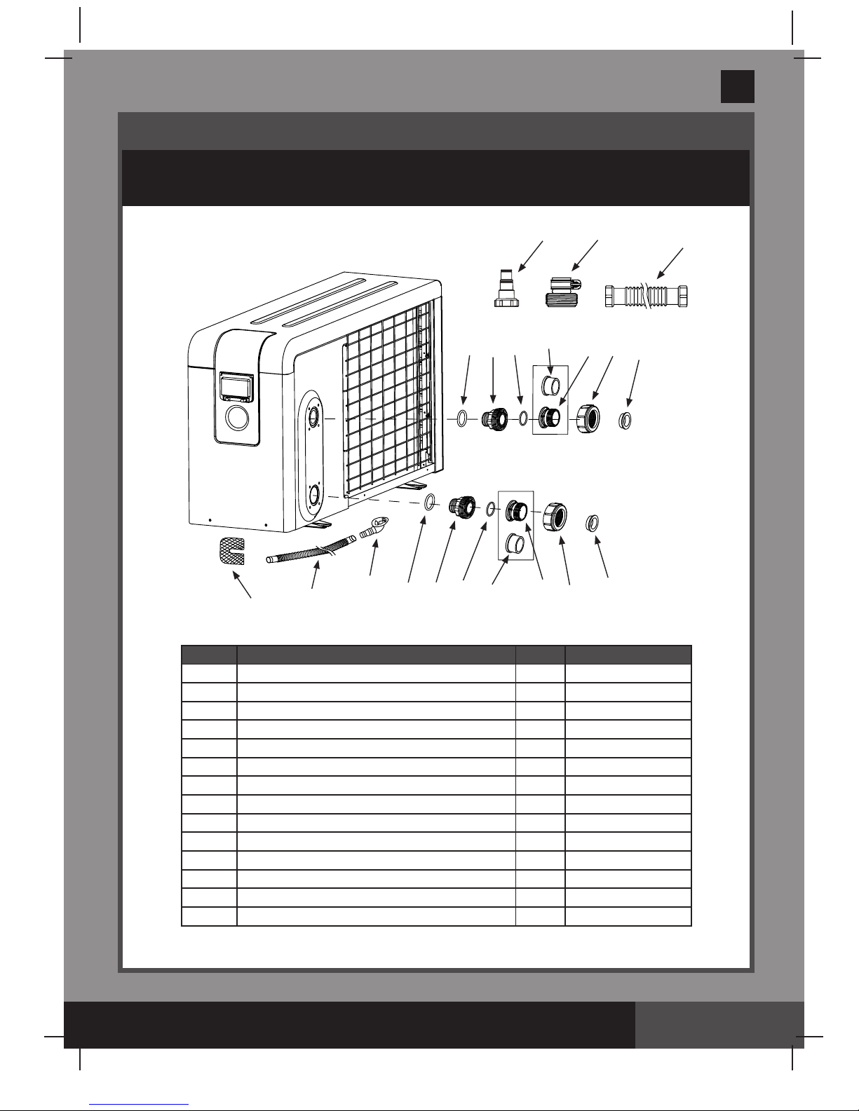
PARTS REFERENCE
Before installing your product, please take a few minutes to check the contents
and become familiar with all the parts.
NOTE:
Drawings for illustration purpose only. Actual product may vary. Not to scale.
When ordering parts, be sure to quote the model number and part numbers.
REF. NO. DESCRIPTION QTY. SPARE PART NO.
1 L-SHAPE O-RING 6 11228
2 HEAT PUMP FITTING NUT 2 12567
3 38MM HOSE ADAPTOR 6 12571
4 HEAT PUMP 50MM PIPE ADAPTOR 2 12555
5 HEAT PUMP FITTING O-RING 2 12557
6
INLET/OUTLET JUNCTION (O-RINGS INCLUDED)
2 12572
7 HEAT PUMP O-RING 2 12568
8 ANTI-VIBRATION PAD 4 12559
9 DRAIN HOSE CONNECTOR 2 12554
10 DRAIN HOSE 2 12563
11 ANCHOR BOLT (NOT SHOWN) 4 12407
12 ADAPTER A 1 10849
13 ADAPTER B 1 10722
14
1M CONNECTOR HOSE WITH THREADED FITTINGS
1 10720
1
1
2
2
3
3
4
4
5
6
7
10
9
8
5
6
7
12
13
14
Page 6

(307IO) HEAT PUMP ENGLISH 7.5” X 10.3” PANTONE 295U 12/15/2016
English
307
IO
SAVE THESE INSTRUCTIONS
English
Page 6
PARTS REFERENCE (continued)
Before installing your product, please take a few minutes to check the contents
and become familiar with all the parts.
NOTE:
Drawings for illustration purpose only. Actual product may vary. Not to scale.
When ordering parts, be sure to quote the model number and part numbers.
REF. NO. DESCRIPTION QTY. SPARE PART NO.
15 BYPASS 50MM PIPE ADAPTOR 4 12562
16 VALVE COLLAR NUT 4 12566
17 1.5M HOSE WITH NUTS 2 11009
18 BYPASS KIT VALVE HANDLE 3 12564
19 BYPASS KIT 1 12573
For 38mm collar nut hose connection
19
3
1
16
1
1
3
16
17
18
For 50mm pipe tting
19
15
16
15
16
18
Page 7
(307IO) HEAT PUMP ENGLISH 7.5” X 10.3” PANTONE 295U 12/15/2016
English
307
IO
SAVE THESE INSTRUCTIONS
English
Page 7
PRODUCT SPECIFICATIONS
*Measured Condition at 27°C Ambient Air, 27°C Water, 80% Humidity
Heat Output 8.20 kW (27,820 Btu) / hr
Power Consumption 1.71 kW (5,800 Btu) / hr
Coefcient of Performance (COP) 4.7
*Measured Condition at 15°C Ambient Air, 26°C Water, 70% Humidity
Heat Output 6.00 kW (20,358 Btu) / hr
Power Consumption 1.53 kW (5,191 Btu) / hr
Coefcient of Performance (COP) 3.9
General Data
Voltage / Frequency / Phase 220 - 240 V / 50 Hz / 1 PH
Rated current 7 A
Advised fuse ≥16 A
Recommended pool water capacity 10 - 22 m³
Required system water ow rate 2.5 - 10 m³/hr
Maximum water pressure 0.4 MPa
Water pressure drop 14 kPa
Operating water temperature range 15°C - 35°C
Operating air temperature range 8°C - 40°C
Class of protection I
Type of protection IPX4
Heat exchanger Titanium inside a PVC reservoir
Compressor / refrigerant type Rotary / R410A
Refrigerant gas quantity 0.95 kg
Inlet / outlet tting size 50 mm glue tting; 38 mm hose with collar nut
Noise level at 10 m / 1 m 43 dB(A) / 48 dB(A)
Fan input power 80 W
Fan speed 830 - 870 RPM
RCD protection 10 mA
Global warming potential (GWP) 2088
CO2 Equivalent 1.99 T
Weight Net / Gross 50 / 69 kg
• Pump and pool must be installed and lled with water prior to installation. Two adults required.
• Tools required: one adjustable wrench, one Philip screwdriver.
• The unit will work properly as long as the following three elements are present:
1. Fresh air 2. Electricity 3. Swimming pool water
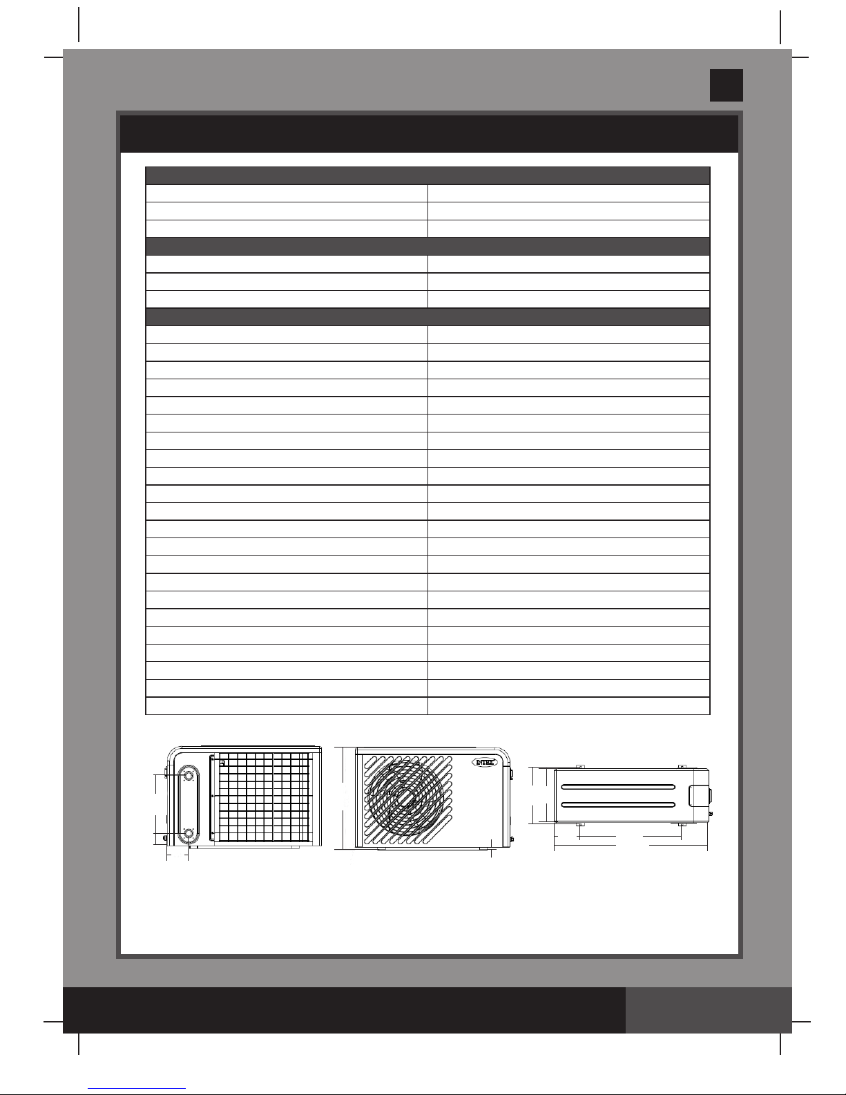
143.4
85.2
230
198
620
1019
370
324
575.5
17.5
(Unit: mm)
* Pool covered with a solar pool cover
Page 8

(307IO) HEAT PUMP ENGLISH 7.5” X 10.3” PANTONE 295U 12/15/2016
English
307
IO
SAVE THESE INSTRUCTIONS
English
Page 8
SET UP INSTRUCTIONS
• Never install the unit in a closed room with a limited air volume in which the air expelled from
the unit will be reused, or close to garden plants that could block the air inlet. Such locations
impair the continuous supply of fresh air, resulting in reduced efciency, performance and
possibly preventing sufcient heat output.
• During normal operations, the heat pump evaporator ns produce condensation water. The
amount of condensation produced varies according to ambient conditions. The higher the air
humidity, the higher the amount of condensation produced (several liters per day). The lower
heat pump panel acts as a condensation collection tray. Keep the drain hole clean.
• The heat pump must be positioned to avoid damages caused by water or condensation
leaks. Install suitable drainage outlets or collection containers.
• The heat pump must be xed and installed on a at, solid, vibration free and level support
(cement slab or prefabricated platform). Do not install the heat pump on unstable ground.
• To reduce noise wave echoes, do not install the heat pump in the immediate vicinity of vertical
walls and use the included anti-vibration pads during installation.
• Make sure the pump is not subject to rain water ows from nearby building roofs. Protruding
roofs without gutters could pour signicant amounts of water and/or debris on the heat pump
which could damage it. If necessary, install gutters or discharge outlets to protect the heat
pump.
• Make sure the heat pump is not within the range of any sprinkler or irrigation systems. If
necessary, install suitable protections.
500mm
300mm
700mm
700mm
2500mm
IMPORTANT
Always keep the unit upright. If the unit has been tilted or put on its side, wait 24 hours
before starting the heat pump.
Location and Space Requirement
• The heat pump must be installed outdoors and more than 2m away from the pool. It can not
be installed indoors.
• Minimum clearance required for the heat pump installation as follow:
Page 9

(307IO) HEAT PUMP ENGLISH 7.5” X 10.3” PANTONE 295U 12/15/2016
English
307
IO
SAVE THESE INSTRUCTIONS
English
Page 9
SET UP INSTRUCTIONS (continued)
Condensation Draining Hose Installation
NOTE:
The air drawn into the heat pump is strongly cooled by the operation of the heat pump for
heating the pool water, which may cause condensation on the evaporator ns. The amount of
condensation may be as much as several liters per hour at high relative humidity. This is
sometimes mistakenly regarded as a water leak.
1.
Slightly tilt the unit to reveal the bottom panel.
2.
Attach the drain hose connector
(9)
to the bottom panel.
3.
Attach the wider end of the drain hose
(10)
to the hose connector and place the other end into
a suitable discharge area.
Water Connection and Bypass Kit Installation
The following retail components (not included) are recommended for the hydraulic connections:
• Cut-off valves upstream and downstream from the heat pump to facilitate maintenance and/or
heat pump bypass from the pool water circulation system.
• A non-return or check valve, installed between the pool and the heat pump outlet tting, to
prevent water reux.
All chemical feeder or water treatment devices must be installed downstream from the heat pump
and non-return (check) valve. It is important to install a check valve to prevent chemical saturated
water reux which could damage the heat pump and void the warranty.
The water circulation system must be arranged observing the following general layout:
Pool Pump Filter Heat Pump Non-return/Check Valve Chemical
Treatment Pool
Heat Pump
Chemical Treatment
Pool
Check Valve
Filter Check Valve
Water Pump
10
9
Page 10

(307IO) HEAT PUMP ENGLISH 7.5” X 10.3” PANTONE 295U 12/15/2016
English
307
IO
SAVE THESE INSTRUCTIONS
English
Page 10
SET UP INSTRUCTIONS (continued)
Typical above ground pool arrangement
Typical in-ground pool arrangement
Pool
Filter
Pump
Chemical
Treatment
Heat Pump
Power
Cable Inlet
Condensation
Draining Pipe
Water to Pool
Water Pump
Filter
Check Valve
Chemical
Treatment
Water
from Pool
NOTE:
To allow water to ow into the heat pump, make sure the valve in the middle of the bypass
kit is closed and the other two valves on the sides are open.
Page 11

(307IO) HEAT PUMP ENGLISH 7.5” X 10.3” PANTONE 295U 12/15/2016
English
307
IO
SAVE THESE INSTRUCTIONS
English
Page 11
SET UP INSTRUCTIONS (continued)
Electrical Connection
Although the heat pump is electrically isolated from the rest of the swimming pool
system, this only prevents the flow of electrical current to or from the water in the pool.
Grounding the heat pump is required for protection against short-circuits inside the
unit. Always provide a good grounding connection outlet. If not sure, contact a
qualified electrician for assistance.
WARNING
Before connecting the unit, verify that the supply voltage matches the operating voltage of the heat
pump.
The heat pump must be connected to a dedicated circuit breaker rated 16 A or more. Make sure
no other appliances are connected to this circuit breaker.
The heat pump is supplied with a power cable and a standard 10mA RCD to be plugged directly
into a grounded electrical outlet. The grounded electrical outlet must have a protection grade not
lower than IPX4.
Test the RCD before use:
1.
Plug the RCD into a grounded electrical outlet.
2.
Press the “RESET” button. The indicator on the RCD should be “ON”.
3.
Press the “TEST” button. The indicator on the RCD should be “OFF”.
4.
Press the “RESET” button again to start using the heat pump.
Do not use the product if the test failed. Contact a qualied electrician to inspect the electrical
outlet socket.
Initial Operation
Make sure the pool is lled with water to the correct level, the skimmer and suction ttings are
below the water level.
To heat the pool water, the lter pump must be running to cause the water to circulate through the
heat pump. The heat pump will not start up if the water is not circulating, therefore the heat pump
must operate together with the lter pump.
After all the water connections have been attached and checked, carry out the following
procedure:
1.
Switch on the lter pump. Check for leaks and verify that water is owing from and to the
swimming pool.
2.
Plug the heat pump and test the RCD (see “
Electrical Connection
” section), the display panel
shows “8888” then “OFF”.
3.
Press the On/Off button on the control unit panel to activate it, the display shows the actual
water temperature. The unit will start up after the time delay expires (see “
Time Delay
”
section).
4.
After a few minutes, check whether the air blowing out of the heat pump fan is cooler.
5.
When the lter pump is turned off, the heat pump should also turn off automatically, if not, then
adjust the ow switch (performed by specialist technician only).
6.
Allow the heat pump and the lter pump to run 24 hours a day until the desired water
temperature is reached. The heat pump will stop running at this point. After this, it will restart
automatically (as long as the lter pump is running) whenever the swimming pool water
temperature drops 2 degrees below the set temperature.
Page 12

(307IO) HEAT PUMP ENGLISH 7.5” X 10.3” PANTONE 295U 12/15/2016
English
307
IO
SAVE THESE INSTRUCTIONS
English
Page 12
SET UP INSTRUCTIONS (continued)
Time Delay
The heat pump has a built-in 1 to 2-minute start-up delay to protect the control circuit components
and avoid excessive restart cycles. The unit will restart automatically after this time delay expires.
Even a brief power interruption will trigger this time delay and prevent the unit from restarting
immediately. Additional power interruptions during this delay period do not affect the 1 to 2-minute
duration of the delay.
Water Flow Switch
The heat pump is equipped with a ow switch to protect it from running without adequate water
ow rate. It will turn on when the pump runs and shut it off when the pump shuts off. If the pool
water level is higher than 1m above or below the heat pump’s automatic ow switch adjustment
knob, your specialist technician may need to adjust the initial startup water ow rate.
Refrigerant Gas Pressure Verication
The following table shows the refrigerant pressure versus heat pump working condition. If there is
big difference between them, the machine is probably malfunctioning.
Heat Pump
Condition
Power Off Running
Ambient temp (°C)
-5-5 5-15 15-25 25-35 / / / / /
Water temp (°C)
/ / / / 10-15 15-20 20-25 25-30 30-35
Pressure gauge
reading (bar)
6.8-9.3 9.3-12.5
12.5-16.4
16.4-21 13-18 15-19 16-23 19-28 21-35
Refrigerant pressure and temperature table
7.
To set the water temperature and program the heat pump, see “
Display Control Panel
Operation
” section for details.
Depending on the initial temperature of the pool water and the ambient air temperature, it may
take several days to heat the pool water to the desired temperature. A good solar pool cover can
reduce the heating time.
Page 13

(307IO) HEAT PUMP ENGLISH 7.5” X 10.3” PANTONE 295U 12/15/2016
English
307
IO
SAVE THESE INSTRUCTIONS
English
Page 13
DISPLAY CONTROL PANEL OPERATION
A: On/Off Button
B: Temperature Increase Button
C: Temperature Decrease Button
D: Set Button
E: LED Display
F: Heating
G: Timer Off
H: Timer On
I: Warning
CONTROL UNIT PANEL
On/Off Button:
Press this button to start the heat pump, the LED display will show the
inlet water temperature and current working mode after 5 seconds. Press once again
to stop the heat pump, the LED display shows “OFF”.
NOTE:
Press this button to save all operation settings and quick-exit the program.
Temperature Adjustment Buttons:
Press the or button to set the desired
water temperature, then press to save setting and exit. Temperature range: 15 to
40°C.
TIME Setting:
Press
set
, then press to enter into “TIME” display.
Hour setting:
Press
set
again to enter into “HOUR” setting, “HH” flashed, then press
the or button to adjust the HOUR from 0 to 23.
Minute setting:
Press
set
to enter into “MINUTE” setting, “MM” flashed, then press
the or button to adjust the MINUTE from 0 to 59.
TIMER ON setting:
Press
set
, then press twice to enter into “TIMER ON” setting.
When the starting time is shown on the LED display, press
set
to confirm to enter into
“TIMER ON” setting interface, finally press the or button to adjust the starting
time. Press to save setting and exit.
TIMER OFF setting:
Press
set
, then press 3 times to enter into “TIMER OFF”
setting.
When the stopping time is shown on the LED display, press
set
to confirm to enter into
“TIMER OFF” setting interface, finally press the or button to adjust the stopping
time. Press to save setting and exit.
LED Display:
Once plugged in the LED displays “8888” then “OFF”.
A
B
CD
E
F
G
I
H
set
+
Page 14

(307IO) HEAT PUMP ENGLISH 7.5” X 10.3” PANTONE 295U 12/15/2016
English
307
IO
SAVE THESE INSTRUCTIONS
English
Page 14
MAINTENANCE
1.
Check the water supply circulation system regularly for water leakage and air entering into the system, as
the performance and reliability of the unit will be reduced.
2.
Clean the pool water and ltration media regularly to maximize the performance and to prevent damage to
the heat pump.
3.
Regularly check all the panels and screws are securely attached.
Disposal and Decommissioning
Collecting recyclable material, both those used for packaging (cardboard, nylon, etc.) and those replaced
during routine and major maintenance is recommended. Suitable collection of waste material for recycling,
processing and environmentally compatible disposal contributes in avoiding possible negative effects on the
environment, health and promotes the reuse and/or recycling of device materials. Incorrect product disposal
by the user may be punishable by current national laws.
When the unit reaches the end of its working life and must be removed and/or replaced, follow the instructions
below:
1.
Refrigerant gas must be collected by specialized technicians and sent to collection centers.
2.
Compressor lubricant oil must be collected by specialized technicians and sent to collection centers.
3.
The housing and other parts, if unusable, should be dismantled and divided according to their material
type (for example, copper, aluminum, plastic, etc.) and must be sent to collection centers.
Winterizing
Failure to winterize could cause damage to the heat pump and void the warranty.
1.
Turn off the heat pump and unplug the power cable from the main electrical outlet. Or turn off the electrical
power at the main circuit breaker panel.
2.
Shut off the water supply (bypass kit) to the heat pump.
3.
Disconnect the IN and OUT water connections and drain out all the water from the heat pump. Use air to
blow out any standing water inside the unit.
4.
Reconnect the IN and OUT connections loosely to prevent debris entering the water connections.
5.
Drain out all the water at the bottom of the heat pump panel.
6.
Protect the heat pump from dirt accumulation. Do not wrap the heat pump with plastic or other material
that can hold heat and/or humidity inside the device. Use the included protective cover.
Spring Startup
If the heat pump has been winterized, perform the following steps when starting the system in the spring:
1.
Remove the protective cover and inspect the unit for any debris or structural problems.
2.
Tighten the IN and OUT water connections securely.
3.
Check the pool water chemical is balanced, see “
Pool Water Chemistry
” section.
4.
Restore water ow to the heat pump, open the valves at the bypass kit and make sure lter pump is ON.
5.
Restore electrical power to the heat pump and test the RCD.
Minimum Ideal Maximum
Free Chlorine
0 0.5 - 3.0 ppm 5.0 ppm
Combined Chlorine
0 0 ppm 0.2 ppm
pH
7.2 7.4 - 7.6 7.8
Total Alkalinity
40 ppm 80 ppm 120 ppm
Calcium Hardness
50 ppm 100 - 250 ppm 350 ppm
Stabilizer (Cyanuric Acid)
10 ppm 20 - 40 ppm 50 ppm
Preferred Water Chemistry Reading
Special care must be taken to keep your pool water chemical balanced within the following limits:
If the concentration of one or more of the above readings becomes too high, irrevocable damage to your heat
pump may occur. Failure to keep the pool water chemical between the limits will void the warranty.
Consult with your local swimming pool dealer for water treatment recommendation.
POOL WATER CHEMISTRY
Page 15

(307IO) HEAT PUMP ENGLISH 7.5” X 10.3” PANTONE 295U 12/15/2016
English
307
IO
SAVE THESE INSTRUCTIONS
English
Page 15
This Flow Chart will teach
you the steps to follow to
protect your heater.
INSTALLATION
- Verify that the installation was done
according to owner's manual instructions.
FIRST TIME OR SPRING STARTUP
- Hook up pool water piping but do not
hook up the Heater yet.
VERIFY & BALANCE POOL CHEMICAL
HOOK UP WATER PIPING TO HEATER
POOL CHEMICAL OK?
SET REQUIRED WATER
TEMPERATURE ON TOUCH PAD
IMPORTANT FOR THE HEALTH OF YOUR FAMILY
AND FOR YOUR POOL HEATER
- Verify Chlorine or Bromine level every 2-3 days.
- Verify pH level once a week.
- Verify Alkalinity level every 3-4 weeks (More often if you own
an Automatic Chlorine or Bromine Feeder.)
- Verify Calcium Hardness once a month.
(Above tests can easily be done by yourself with a do it yourself kit.)
HEATING WILL NOT BE REQUIRED
FOR MORE THAN A WEEK?
Shut Bypass valves and disconnect waterlines
to drain the HEATER.
HEATING NEEDED?
IS IT POOL CLOSING
TIME?
CLOSE POOL
PROTECT HEATER BY COVERING IT
INSTALLATION
When heating is not required for
less than a week you MUST leave
the Bypass valves open (see drawing
above) to let the water circulate in the
unit. If the heat exchanger is deprived
of water circulation for more than
72 hours, high chlorine could
cause excessive corrosion.
NO
YES
NO
YES
YES
NO
YES
NO
CLOSED
OPEN
HEAT PUMP CARING
Page 16

(307IO) HEAT PUMP ENGLISH 7.5” X 10.3” PANTONE 295U 12/15/2016
English
307
IO
SAVE THESE INSTRUCTIONS
English
Page 16
TROUBLESHOOTING
IMPORTANT
• Installation, service and maintenance must be performed by qualified
technician.
• If you continue to experience difficulty, please contact our Consumer
Service Department for assistance. See separate “Authorized Service
Centers” sheet.
THE HEAT PUMP
DOES NOT TURN
ON AND LED
DISPLAY IS BLANK.
THE HEAT PUMP
DOES NOT TURN
ON AND LED
DISPLAY SHOWS
“OFF”.
THE HEAT PUMP
DOES NOT START
AND LED DISPLAY
SHOWS ACTUAL
WATER
TEMPERATURE.
THE HEAT PUMP
IS RUNNING BUT
THE WATER IS NOT
HEATING.
WATER LEAKS
FROM THE HEAT
PUMP.
• Not plugged in, the instructions in “Initial
Operation” section were not followed.
• RCD is not “RESET”.
• RCD and/or house circuit breaker
tripped.
• On/Off button not responding.
• The 1 to 2 minutes “Time Delay”
required for the unit to start have not
elapsed. See “Time Delay” section.
• Water temperature is greater than or
equal to set temperature.
• Make sure air is blowing out from the
fan front grid side of the heat pump.
• The heat pump was just installed.
• Pool water has significantly cooled
down since the last heat pump use.
• Ambient temperature too low.
• Temperature set too low.
• Evaporator fins dirty.
• Water flow rate has decreased.
• Refrigerant gas pressure lower.
• Compressor failure.
• Probable accumulation of condensation.
• Possible water leak from the water
exchanger or from hydraulic unit
connection devices.
• Follow the instructions in “Initial Operation” section.
• Reset the RCD, see “Electrical Connection” section.
• Contact a qualified electrician to identify and correct the
fault in the electrical line and socket.
• Press the On/Off button firmly few times.
• Contact qualified technician to replace the Controller Unit
Panel.
• Wait until the 1-2 minutes have elapsed. See “Time
Delay” section.
• The unit will start when the water temperature is lower
than the set temperature.
• Make sure adequate air circulation; see “Location and
Space Requirement” section.
• 24 – 48 hours may be required to reach the set
temperature. Put a solar pool cover over the pool.
• 24 – 36 hours may be required to reach the set
temperature. Put a solar pool cover over the pool.
• Wait until ambient temperature rises to start the heat
pump.
• Increase the temperature setting and put a solar pool
cover over the pool.
• Clean the evaporator fins.
• Check circulation line, bypass kit for leakage and clean
the filter media.
• See “Refrigerant Gas Pressure Verification” section.
Contact qualified technician to refill refrigerant.
• Contact qualified technician to check compressor
connection. Replace compressor and/or PCB.
• Stop the heat pump for 1 hour, if the leak stops, this is
normal condensation.
• Make sure all hoses, pipes, bypass kit are securely
connected and tightened.
PROBLEM
CAUSE
SOLUTION
Page 17

(307IO) HEAT PUMP ENGLISH 7.5” X 10.3” PANTONE 295U 12/15/2016
English
307
IO
SAVE THESE INSTRUCTIONS
English
Page 17
SERVICE BY QUALIFIED TECHNICIANS
• Set/Adjust the parameters:
1.
Press
set
+ + at same time for 5 seconds, display flashes.
2.
Press or to choose the parameter you want to adjust.
3.
Press
set
again to enter into interface.
4.
Press or to adjust the value setting.
5.
Finally press
set
once again to save the data or press to save and quick-exit the
parameter setting.
Parameter Meaning Range Default Remarks
1 To set the entering water temp. under heating mode 15-42°C 28°C Adjustable
7 Mode selection of Electronic expansion valve 0-1 1 (auto) Adjustable
A Manual adjustment of electronic expansion valve 18-94 70 Adjustable
L Entering water temperature calibration -9.9-9.9 0 Adjustable
Recover to Factory default setting
Long press and
set
simultaneously for 10 seconds to recover to factory default setting, it will
display “0000” and then back to “OFF”.
Parameter Setting
The following sections shall be operated only by qualified technicians for after-service or
maintenance.
• Check the parameters:
Press
set
, then press to check the parameter of B - C - D - E - F - G.
Code Parameter Range Code Parameter Range
B Water in temperature -9 to 99°C C Water out temperature -9 to 99°C
D Heating pipe temperature -29 to 99°C E Gas return temperature -29 to 99°C
F Ambient temperature -29 to 99°C G Cooling pipe temperature -9 to 99°C
IMPORTANT:
When you press
set
and press button to enter into parameter checking, the
button could not be operated. Also, when you press
set
and press button to check TIME -
starting time of TIMER and Stopping time of TIMER, the could be not operated.
Page 18

(307IO) HEAT PUMP ENGLISH 7.5” X 10.3” PANTONE 295U 12/15/2016
English
307
IO
SAVE THESE INSTRUCTIONS
English
Page 18
SERVICE BY QUALIFIED TECHNICIANS (continued)
LED Display Error Code
ERROR CODE
SHOWN ON LED
DISPLAY
CAUSE SOLUTION
• Frost on evaporator fins:
ambient air temperature is lower
than the minimum operating air
temperature range 8°C.
• Check ambient air temperature variation, specially from day
time to mid-night. Wait until ambient air temperature rises for
the heat pump to start up.
• Switch off unit for few minutes and switch on again, check
if: a) fan is not running, replace damaged fan motor. b) fan is
running, then make sure adequate air circulation, see
“Location and Space Requirement” section.
• Water inlet temperature sensor
broken.
• Check T1 temperature sensor connection.
• T1 temperature sensor broken, replace T1 sensor.
• Terminal block for T1 connection on PCB broken, replace
PCB.
• Water outlet temperature sensor
broken.
• Check T2 temperature sensor connection.
• T2 temperature sensor broken, replace T2 sensor.
• Terminal block for T2 connection on PCB broken, replace
PCB.
• Evaporator fins temperature
sensor broken.
• Check T3 temperature sensor connection.
• T3 temperature sensor broken, replace T3 sensor.
• Terminal block for T3 connection on PCB broken, replace
PCB.
• Ambient air temperature sensor
broken.
• Check T5 temperature sensor connection.
• T5 temperature sensor broken, replace T5 sensor.
• Terminal block for T5 connection on PCB broken, replace
PCB.
• High pressure protection.
• Check bypass valves setting.
• Check system water flow is according to “Product
Specification” section.
• Check high pressure sensor connection (HP & GND).
• High pressure sensor broken, replace it.
• Terminal block for high pressure sensor connection on PCB
broken, replace PCB.
• Low pressure protection.
• Check for refrigerant gas leakage, see “Refrigerant Gas
Pressure Verification” section. Refill as needed.
• Ambient air temperature is lower than the minimum
operating air temperature range, wait until ambient air
temperature rises.
• Switch off unit for few minutes and switch on again, check if:
a) fan is not running, replace damaged fan motor. b) fan is
running, then make sure adequate air circulation, see
“Location and Space Requirement” section.
• Check low pressure sensor connection (LP & GND).
• Low pressure sensor broken, replace it.
• Terminal block for low pressure connection on PCB broken,
replace PCB.
Or
• No water flow or low water flow.
• Verify if water inlet and outlet hoses/pipes are connected
correctly.
• Ensure pool inlet and outlet cover grid is clean and free from
obstructions.
• Check if filtration pump is working.
• Clean or replace the cartridge or sand media if necessary.
• Check bypass valves setting.
• Keep the pool water properly sanitized.
• Water flow sensor broken, replace it.
• Check flow sensor connection (FS & GND).
• Communication failure.
• Check electrical connection between control unit panel and
main PCB. Replace control unit panel.
• Check control wire connection (NET).
• PCB terminal connection block broken, replace PCB.
Page 19

(307IO) HEAT PUMP ENGLISH 7.5” X 10.3” PANTONE 295U 12/15/2016
English
307
IO
SAVE THESE INSTRUCTIONS
English
Page 19
Use the following procedure to adjust the bypass:
• Fully open all three valves.
• Slowly close valve 1 until the water pressure is increased and until the water ow switch is on.
• Close valve 3 approximately half-way to adjust the gas pressure in the cooling system.
• If the display shows “ON” or error code EE3, close step by step the valve 2, to increase water
ow and stop when the code disappear.
Optimal operation of the heat pump occurs when the cooling gas pressure is 22 ± 2 bar.
This pressure can be read on the pressure gauge next to the control heat pump panel. Under
these conditions the water ow through the unit is also optimal.
NOTE:
Operation without a bypass or with improper bypass adjustment may result in sub-optimal
heat pump operation and possibly damage to the heat pump, which renders the warranty null and
void.
SERVICE BY QUALIFIED TECHNICIANS (continued)
To Pool
From Pool
Heat Pump
In
Out
Valve 1
Valve 3 Valve 2
Page 20

(307IO) HEAT PUMP ENGLISH 7.5” X 10.3” PANTONE 295U 12/15/2016
English
307
IO
SAVE THESE INSTRUCTIONS
English
Page 20
SERVICE BY QUALIFIED TECHNICIANS (continued)
Regulation (EU) No 517/2014 of 16/04/14 on uorinated greenhouse gases
and repealing Regulation (EC) No 842/2006
Leak checks
Operators of equipment that contains uorinated greenhouses gases in quantities of 5 tons of
CO2, equivalent or more and not contained in foams shall ensure that the equipment is checked
for leaks.
Leak checks frequency – for equipment that contains uorinated greenhouse gases in quantities
of 5 tons of CO2 equivalent or more, but of less than 50 tons of CO2 equivalent: at least every
12 months.
Equivalent CO
2
Load in kg and Tons amounting CO
2
Load and Tons amounting CO
2
Frequency of test
From 2 at 30 kg load = from 5 at 50 Tons Each year
Concerning Gas R 410a, 2.39kg amounting at 5 tons of CO2, commitment to check each
year.
Training and certication
The operator of the relevant application shall ensure that the relevant personnel have obtained
the necessary certication, which implies appropriate knowledge of the applicable regulations and
standards as well as the necessary competence in emission prevention, recovery of uorinated
greenhouse gases and safe handling of the relevant type and size of equipment covered by the
certicate.
Record keeping
Operators of equipment which is required to be checked for leaks shall establish and maintain
records for each piece of such equipment specifying the following information:
a) The quantity and type of uorinated greenhouse gases installed;
b) The quantities of uorinated greenhouse gases added during installation, maintenance or
servicing or due to leakage;
c) Whether the quantities of installed uorinated greenhouse gases have been recycled or
reclaimed, including the name and address of the recycling or reclamation facility and, where
applicable, the certicate number;
d) The quantity of uorinated greenhouse gases recovered;
e) The identity of the undertaking which installed, serviced, maintained and where applicable
repaired or decommissioned the equipment, including, where applicable, the number of its
certicate;
f) The dates and results of the checks carried out;
g) If the equipment was decommissioned, the measures taken to recover and dispose of the
uorinated greenhouse gases.
The operators shall keep the records for at least ve years, and the undertakings carrying
out the activities for operators shall keep copies of the records for at least ve years.
Page 21

(307IO) HEAT PUMP ENGLISH 7.5” X 10.3” PANTONE 295U 12/15/2016
English
307
IO
SAVE THESE INSTRUCTIONS
English
Page 21
SERVICE BY QUALIFIED TECHNICIANS (continued)
Parts Diagram (for qualied technician use only).
Page 22

(307IO) HEAT PUMP ENGLISH 7.5” X 10.3” PANTONE 295U 12/15/2016
English
307
IO
SAVE THESE INSTRUCTIONS
English
Page 22
REF. NO.
DESCRIPTION
REF. NO.
DESCRIPTION
1 TOP COVER 26 EXHAUST PIPE
2 TOP FRAME 27
HIGH PRESSURE PROTECTION SWITCH
3 AMBIENT TEMPERATURE SENSOR 28 RETURN PIPE
4
AMBIENT TEMPERATURE SENSOR CLIP
29
LOW PRESSURE PROTECTION SWITCH
5 DISTRIBUTOR SETS 30 SUCTION VALVE
6 BACK GRID 31 BASE TRAY
7 EVAPORATOR 32 TITANIUM EXCHANGER
8 PILLAR 33 PLUG
9 LEFT SIDE GRID 34 COLLECTION PIPE SETS
10 FAN MOTOR STAND 35 WATER INLET RUBBER RING (BLUE)
11 ELECTRIC BOX COVER 36 RIGHT SIDE PANEL
12 FAN MOTOR 37 ELECTRIC CABLE CONNECT
13 FAN BLADE 38 PIPE (EXCHANGER TO CAPILLARY)
14 LOGO 39 PRESSURE GAUGE
15 FRONT PANEL 40 WATER FLOW SWITCH
16 FRONT GRID 41 WATER OUTLET RUBBER RING (RED)
17 TRANSFORMER 42 UNION
18 COMPRESSOR CAPACITANCE 43 PIPE (EXCHANGER TO CAP NUT)
19 ELECTRIC BOX 44 BACK PANEL
20 ISOLATED PANEL 45 CONTROLLER HOLDER
21 MAIN BOARD 46 ELECTRIC CABLE CONNECT
22 FAN MOTOR CAPACITANCE 47
WATER PROOF CONTROLLER BOX (WITH SEAL RING)
23 FIVE POSITION TERMINAL BLOCK 48 CONTROLLER
24 CLIP 49 WIRING COVER
25 COMPRESSOR
SERVICE BY QUALIFIED TECHNICIANS (continued)
Page 23

(307IO) HEAT PUMP ENGLISH 7.5” X 10.3” PANTONE 295U 12/15/2016
English
307
IO
SAVE THESE INSTRUCTIONS
English
Page 23
PARTS LIST
Your Heat Pump has been manufactured using the highest quality materials and workmanship.
All Intex products have been inspected and found free of defects prior to leaving the factory. This
limited warranty applies only to the Heat Pump and accessories listed below.
This limited warranty is in addition to, and not a substitute for, your legal rights and remedies. To
the extent that this warranty is inconsistent with any of your legal rights, they take priority. For
example, consumer laws across the European Union provide statutory warranty rights in
addition to the coverage you receive from this limited warranty: for information on EU-wide
consumer laws, please visit the European Consumer Center website at http://ec.europa.eu/
consumers/ecc/contact_en/htm.
The provisions of this limited warranty apply only to the original purchaser and is not
transferable. This limited warranty is valid for the period noted below from the date of the initial
retail purchase. Keep your original sales receipt with this document, as proof of purchase will be
required and must accompany warranty claims or the limited warranty will be invalid.
Heat Pump Warranty – 2 Years
If you find a manufacturing defect in the Heat Pump during the warranty periods noted above,
please contact the appropriate Intex Service Center listed in the separate “Authorized Service
Centers” sheet. If the item is returned as directed by the Intex Service Center, the Service Center
will inspect the item and determine the validity of the claim. If the item is covered by the
provisions of the warranty, the item will be repaired or replaced, with the same or comparable
item (at Intex’s choice) at no charge to you.
Other than this warranty, and other legal rights in your country, no further warranties are implied.
To the extent possibly in your country, in no event shall Intex be liable to you or any third party
for direct or consequential damages arising out of the use of your Heat Pump, or Intex or its
agents’ and employees’ actions (including the manufacture of the product). If your country does
not allow the exclusion or limitation of incidental or consequential damages, this limitation or
exclusion does not apply to you.
You should note that this limited warranty does not apply in the following circumstances:
• If the Heat Pump is subject to negligence, abnormal use or application, accident, improper
operation, improper voltage or current contrary to operating instructions, improper
maintenance or storage;
• If the Heat Pump is subject to damage by circumstances beyond Intex’s control, including but
not limited to, ordinary wear and tear and damage caused by exposure to fire, flood, freezing,
rain, or other external environmental forces;
• To parts and components not sold by Intex; and/or
• To unauthorized alterations, repairs or disassembly to the Heat Pump by anyone other than
Intex Service Center personnel.
The costs associated with the loss of pool water, chemicals or water damage are not covered by
this warranty. Injury or damage to any property or person is not covered by this warranty.
Read the owner’s manual carefully and follow all instructions regarding proper operation and
maintenance of your Heat Pump. Always inspect your product prior to use. This limited warranty
will be void if use instructions are not followed.
LIMITED WARRANTY
 Loading...