

Page 1
261A
(261IO) Sand Filter Pump & Saltwater System with Electrocatalysis Oxidation (14” & 16”) ENGLISH 7.5” X 10.3” PANTONE 295U 08/04/2014
English
IMPORTANT
SAFETY RULES
Read, understand, and follow
all instructions carefully before
installing and using this product.
Don’t forget to try these other fine Intex products: pools, pool
accessories, inflatable pools and in-home toys, airbeds and boats
available at fine retailers or visit our website.
Due to a policy of continuous product improvement, Intex
reserves the right to change specifications and appearance,
which may result in updates to the instruction manual without
notice.
OWNER’S MANUAL
©2014 Intex Marketing Ltd. - Intex Development Co. Ltd. - Intex Trading Ltd.
- Intex Recreation Corp.
All rights reserved/Tous droits réservés/Todos los derechos reservados/Alle
Rechte vorbehalten. Printed in China/Imprimé en Chine/Impreso en China/Gedruckt in China.
®™ Trademarks used in some countries of the world under license from/®™ Marques utilisées dans certains pays sous
licence de/Marcas registradas utilizadas en algunos países del mundo bajo licencia de/Warenzeichen verwendet in einigen
Ländern der Welt in Lizenz von/Intex Marketing Ltd. to/à/a/an Intex Trading Ltd., Intex Development Co. Ltd., G.P.O
Box 28829, Hong Kong & Intex Recreation Corp., P.O. Box 1440, Long Beach, CA 90801 • Distributed in the European
Union by/Distribué dans l’Union Européenne par/Distribuido en la unión Europea por/Vertrieb in der Europäischen Union
durch/Intex Trading B.V., Venneveld 9, 4705 RR Roosendaal – The Netherlands
www.intexcorp.com
For illustrative purposes only.
Model ECO15220 220
–
230V~,
Model ECO15230 230
–
240V~, 6 m3 ;
Model ECO20220 220 – 230V~,
Model ECO20230 230 – 240V~, 8 m
3
261-*A*-R0-1508
Page 2

261A
SAVE THESE INSTRUCTIONS
(261IO) Sand Filter Pump & Saltwater System with Electrocatalysis Oxidation (14” & 16”) ENGLISH 7.5” X 10.3” PANTONE 295U 08/04/2014
English
Page 2
Warnings
.........................................................................................
3
Parts References
...........................................................................
4-5
Setup Instructions
........................................................................
6-13
Product Specifications
..................................................................
8
Operating Instructions
.................................................................
14-18
LED Code Chart
.............................................................................
19
Salt & Pool Water Volumes
..........................................................
20
Intex Pools Salt Table
....................................................................
21
Intex Pools Cyanuric Acid Table............................................
......
22
Intex Pools Operating Time Table
...............................................
23
Non-Intex Pools Salt Table
............................................................
24
Non-Intex Pools Cyanuric Acid Table.......................................... 24
Non-Intex Pools Operating Time Table
........................................
24
Maintenance
....................................................................................
25-29
Long Term Storage
........................................................................
29
Troubleshooting Guide
.................................................................
30-32
Common Pool Problems
...............................................................
33
General Aquatic Safety
.................................................................
33
Limited Warranty
...........................................................................
34
TABLE OF CONTENTS
Page 3
261A
SAVE THESE INSTRUCTIONS
(261IO) Sand Filter Pump & Saltwater System with Electrocatalysis Oxidation (14” & 16”) ENGLISH 7.5” X 10.3” PANTONE 295U 08/04/2014
English
Page 3
IMPORTANT SAFETY RULES
Read, Understand and Follow All Instructions Carefully Before Installing and Using this Product.
READ AND FOLLOW ALL INSTRUCTIONS
WARNING
• To reduce the risk of injury, do not permit children to use this product. Always supervise children and those
with disabilities.
• Children must stay away from this product and electrical cord(s).
• Children shall not play with the appliance. Cleaning and user maintenance shall not be made by children
without supervision.
• This appliance can be used by children aged from 8 years and above and persons with reduced physical,
sensory or mental capabilities or lack of experience and knowledge if they have been given supervision or
instruction concerning use of the appliance in a safe way and understand the hazards involved.
• Assembly and disassembly by adults only.
• The pump must be supplied through a residual current device(RCD) having a rated residual operating current
not exceeding 30mA.
• Always unplug this product from the electrical outlet before removing, cleaning, servicing or making any
adjustment to the product.
• Do not bury the electrical cord. Locate the cord where it will not be damaged by lawn mowers, hedge
trimmers and other equipment.
• If the supply cord is damaged, it must be replaced by the manufacturer, its service agent or similarly qualified
persons in order to avoid a hazard.
• To reduce the risk of electric shock, do not use extension cords, timers, plug adaptors or converter plugs to
connect unit to electric supply; provide a properly located outlet.
• Do not attempt to plug in or unplug this product while standing in water or when your hands are wet.
• Keep this product more than 2m away from the pool.
• Keep this product more than 3.5m away from the pool (for France only).
• Keep the plug of this product more than 3.5m away from the pool.
• Position this product away from the pool, so as to prevent children from climbing on it and accessing the pool.
• The pump must not be used when people are in the water.
• This product is for use with storable pools only. Do not use with permanently installed pools. A storable pool
is constructed so that it may be readily disassembled for storage and reassembled to its original configuration.
• To reduce the risk of entrapment hazard, never enter the pool if suction strainer component is loose, broken,
cracked, damaged or missing. Replace loose, broken, damaged, cracked or missing suction strainer
components immediately.
• Never play or swim near suction fittings. Your body or hair may be trapped causing permanent injury or
drowning.
• To prevent equipment damage and risk of injury, always turn pump off before changing the filter control valve
position.
• Never operate this product above the maximum working pressure stated on the filter tank.
• Hazardous Pressure. Improper tank valve cover assembly could cause the valve cover to blow off and cause
serious injury, property damage or death.
• This product is intended to be used only for the purposes described in the manual!
FAILURE TO FOLLOW THESE WARNINGS MAY RESULT IN PROPERTY DAMAGE, ELECTRIC SHOCK,
ENTANGLEMENT OR OTHER SERIOUS INJURY OR DEATH.
These product warnings, instructions and safety rules provided with the product represent some common risks
of water recreation devices and do not cover all instances of risk and danger. Please use common sense and
good judgement when enjoying any water activity.
Page 4
261A
SAVE THESE INSTRUCTIONS
(261IO) Sand Filter Pump & Saltwater System with Electrocatalysis Oxidation (14” & 16”) ENGLISH 7.5” X 10.3” PANTONE 295U 08/04/2014
English
Page 4
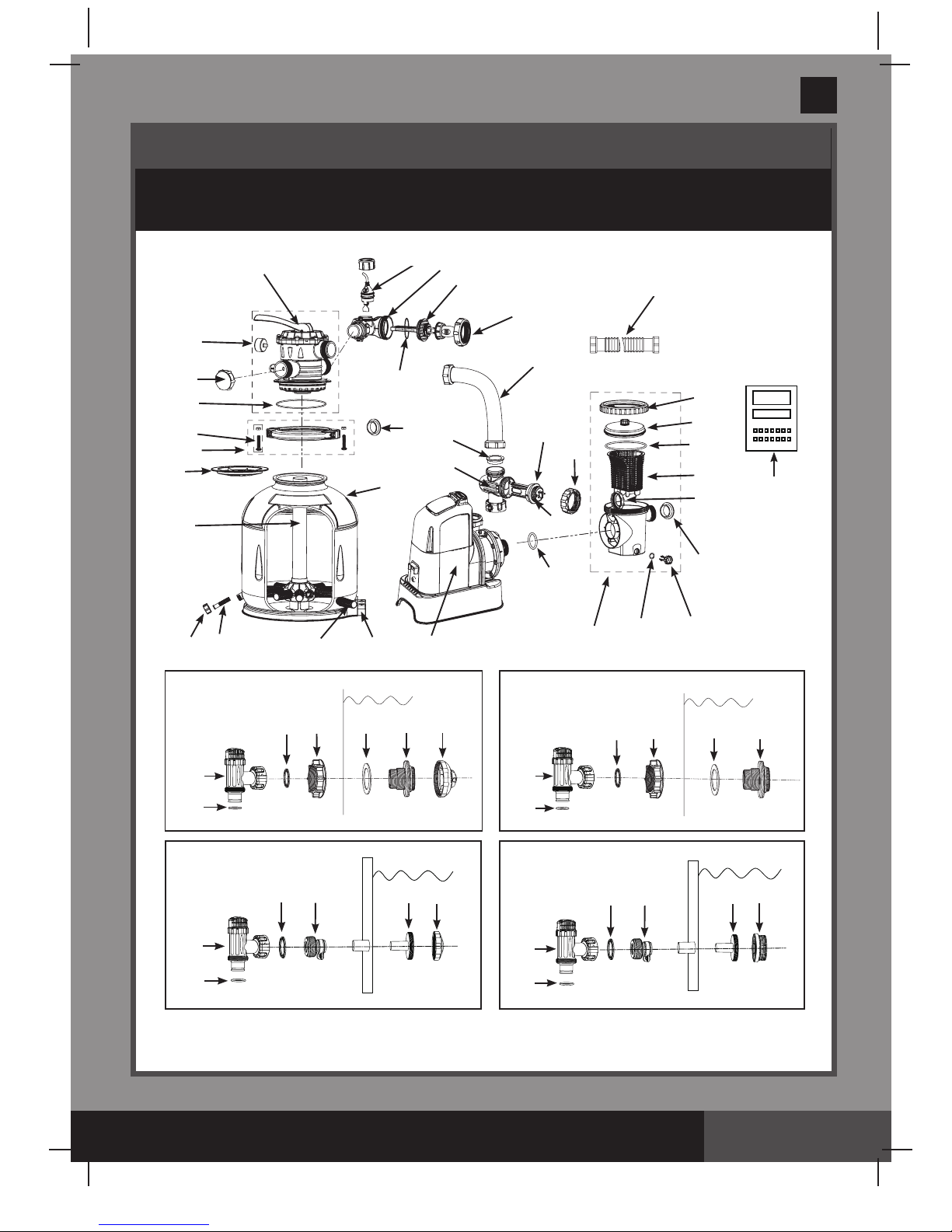
PARTS REFERENCE
Before assembling your product, please take a few minutes to check the contents
and become familiar with all the parts.
" * ": Optional.
NOTE: Drawings for illustration purpose only. Actual product may vary. Not to scale.
28
29
30
31
32
33
34
28
29
30 31
32
33
28
29
30
35
36
37
28
29
30
35
36
38
*
*
*
*
1
5
9
10
11
21
2
13
20
19
3
6
7
4
12
15
16
17
18
8
22
23
24
25
26
27
40
18
14
46
47
48
41
42
45
43
44
39
Page 5
261A
SAVE THESE INSTRUCTIONS
(261IO) Sand Filter Pump & Saltwater System with Electrocatalysis Oxidation (14” & 16”) ENGLISH 7.5” X 10.3” PANTONE 295U 08/04/2014
English
Page 5
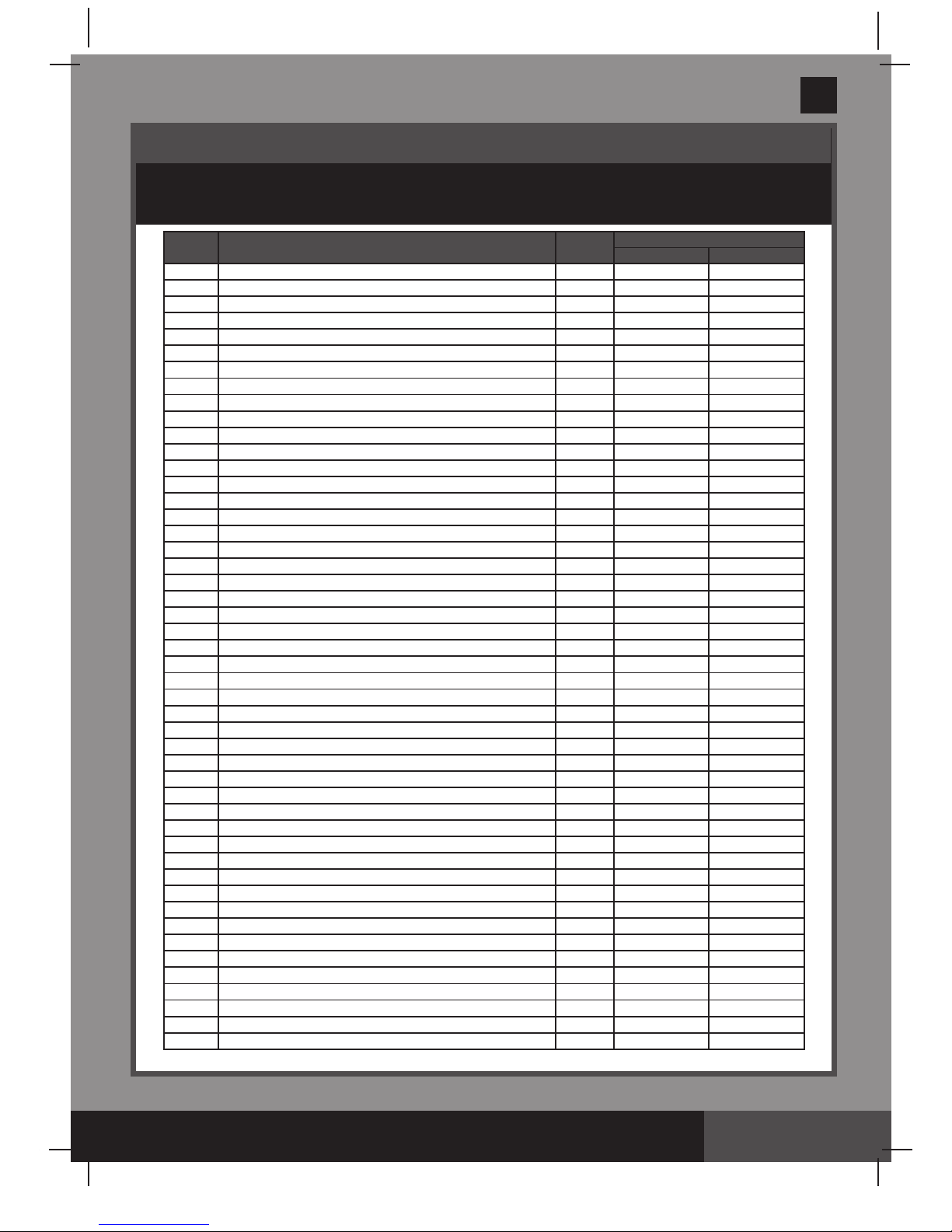
" * ": Optional.
When ordering parts, be sure to quote the model number and part numbers.
PARTS REFERENCE (continued)
Before assembling your product, please take a few minutes to check the contents
and become familiar with all the parts.
REF. NO. DESCRIPTION QTY.
SPARE PART NO.
ECO20220/ECO20230 ECO15220/ECO15230
1 PRESSURE GAUGE 1 11224 11411
2 6-WAY VALVE SET 1 11496 11378
3 DRAIN OUTLET COVER 1 11131 11131
4 TANK O-RING 1 11379 11379
5 SCREW 2 11381 11381
6 CLAMP 1 11380 11380
7 SAND SHIELD 1 11382 11382
8 CENTER PIPE HUB 1 11814 11813
9 DRAIN VALVE CAP 1 11456 11456
10 DRAIN VALVE O-RING 1 11385 11385
11 LATERAL 10 11384 11384
12 HOSE WITH NUTS 2 11010 11010
13 SAND FILTER INTERCONNECTING HOSE 1 11536 11390
14 LEAF TRAP NUT 1 11479 11479
15 LEAF TRAP O-RING 1 11232 11232
16 BASKET 1 11260 11260
17 FILTER HOUSING NUT 1 11261 11261
18 L-SHAPE O-RING 4 11228 11228
19 SEDIMENT RELEASE VALVE 1 10460 10460
20 VALVE O-RING 1 10264 10264
21 FLOW SENSOR 1 11460 11460
22 ELECTROLYTIC CELL 1 11372 11372
23 TITANIUM ELECTRODE 1 11374 11389
24 E.C.O. ELECTRODE 1 11905 11900
25 PRE-FILTER ASSEMBLY 1 11371
11371
26 PUMP MOTOR & CONTROL 1 11914/11914BS 11912/11912BS
27 L-SHAPE O-RING 1 11439 11439
28*
PLUNGER VALVE (HOSE O-RING & STEP WASHER INCLUDED)
2 10747 10747
29* HOSE O-RING 2 10262 10262
30* STEP WASHER 2 10745 10745
31* STRAINER NUT 2 10256 10256
32* FLAT STRAINER RUBBER WASHER 2 10255 10255
33*
THREADED STRAINER CONNECTOR
2 11235 11235
34* ADJUSTABLE POOL INLET NOZZLE 1 11074 11074
35* ADAPTOR B 2 10722 10722
36* STRAINER CONNECTOR 2 11070 11070
37* POOL INLET NOZZLE 1 11071 11071
38* STRAINER GRID 1 11072 11072
39 TEST STRIPS 1 19635 19635
40 LEAF TRAP COVER 1 11480 11480
41 ELECTROLYTIC CELL NUT 1 11432 11432
42 TITANIUM ELECTRODE O-RING 1 11585 11585
43 CELL HOUSING 1 11915 11915
44 SAND FILTER PUMP MOTOR INLET O-RING 2 11457 11457
45 ELECTROLYTIC CELL NUT 1 11582 11582
46 SAND FILTER PUMP AND COMBO TANK 1 11803 11802
47 SAND FILTER PUMP TANK BASE 1 11801 11800
48 O-RING ON TITANIUM PLATES 1 11515 11515
Page 6
261A
SAVE THESE INSTRUCTIONS
(261IO) Sand Filter Pump & Saltwater System with Electrocatalysis Oxidation (14” & 16”) ENGLISH 7.5” X 10.3” PANTONE 295U 08/04/2014
English
Page 6
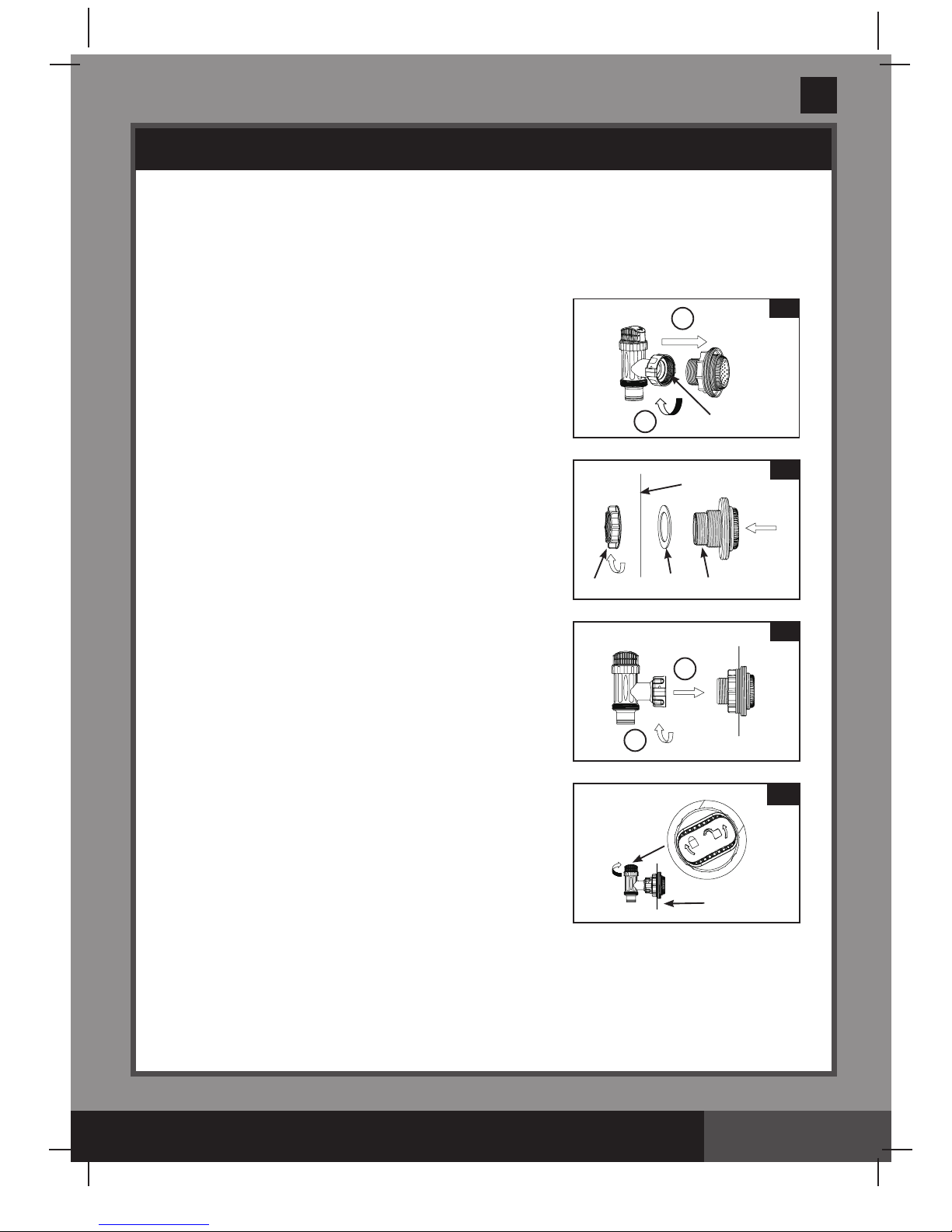
The strainer grid prevents large objects from jamming and/or damaging the filter pump. If
your pool has an inflatable top ring, install the strainer, nozzle and plunger valve before
inflating the pool liner top ring. The part numbers here onward refer to the parts depicted
in the Parts List section of this manual. To install, do the following:
1.
In a counter-clockwise motion unscrew plunger valve
union from the threaded strainer connector
(33) (see
drawing 1).
Be careful not to lose the step rubber
washer
(30). Place the plunger valve on the ground in
a safe place.
2.
In a counter-clockwise motion unscrew the strainer nut
(31) from the threaded connector (33). Leave the flat
washer
(32) on the connector (33).
3.
Install the strainer and plunger valve at the lower
position of pool outlet (marked "+").
From the inside of
the pool liner insert the connector
(33) into one of the
pre-cut holes with the washer remaining on the
connector to be placed against the inside of the liner
wall.
4.
Before assembly, lubricate the threads with a petroleum
jelly. With the flat side of the strainer nut
(31) facing
the outside wall of the liner in a clockwise motion screw
the strainer nut
(31) back onto the threaded connector
(33) (see drawing 2).
5.
Finger tighten the strainer nut (31) onto the threaded
connector
(33).
6.
Grasp the plunger valve assembly. Make sure the step
washer
(30) is in place.
7.
In a clockwise motion screw the plunger valve union
back onto the threaded connector (33) (see drawing 3).
8.
In a clockwise motion turn the plunger valve handle to
close position. Ensure the plunger valve is securely
closed. This will prevent water from flowing out during
filling of the pool
(see drawings 4).
POOL OUTLET - STRAINER & PLUNGER VALVE SETUP (optional)
2
32
33
INSIDE
LINER WALL
31
3
1
2
1
2
1
30
4
INSIDE
LINER WALL
Page 7
261A
SAVE THESE INSTRUCTIONS
(261IO) Sand Filter Pump & Saltwater System with Electrocatalysis Oxidation (14” & 16”) ENGLISH 7.5” X 10.3” PANTONE 295U 08/04/2014
English
Page 7
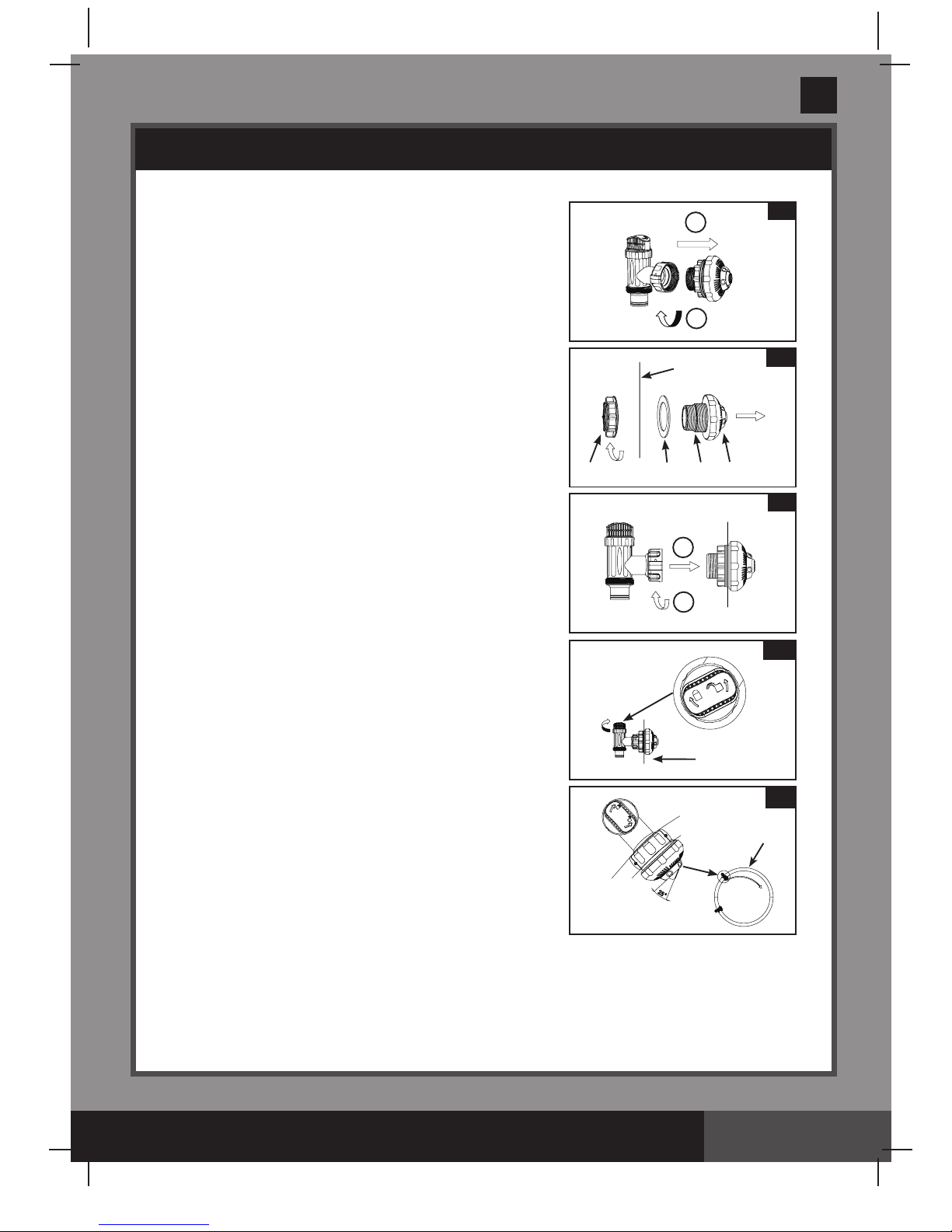
POOL INLET - NOZZLE & PLUNGER VALVE SETUP (optional)
1.
In a counter-clockwise motion unscrew plunger valve
union from the threaded strainer connector
(33) (see
drawing 5).
Be careful not to lose the step rubber
washer
(30). Place the plunger valve on the ground in
a safe place.
2.
In a counter-clockwise motion unscrew the strainer
nut
(31) from the threaded connector (33). Leave the
flat washer
(32) on the connector (33).
3.
Install the nozzle and plunger valve at the upper
position of pool inlet.
From the inside of the pool liner
insert the connector
(33) into one of the pre-cut holes
with the washer remaining on the connector to be
placed against the inside of the liner wall.
4.
Before assembly, lubricate the threads with a
petroleum jelly. With the flat side of the strainer nut
(31)
facing the outside wall of the liner in a clockwise
motion screw the strainer nut
(31) back onto the
threaded connector
(33) (see drawing 6).
5.
Finger tighten the adjustable pool inlet nozzle (34) and
the strainer nut
(31) onto the threaded connector (33).
6.
Grasp the plunger valve assembly. Make sure the step
washer
(30) is in place.
7.
In a clockwise motion screw the plunger valve union
back onto the threaded connector (33) (see
drawing 7)
.
8.
In a clockwise motion turn the plunger valve handle
to close position. Ensure the plunger valve is securely
closed. This will prevent water from flowing out during
filling of the pool
(see drawing 8).
9
. Adjust the direction of nozzle head pointing away from
the pool outlet for a better circulation result
(see
drawing 9)
.
10.
The pool liner is now ready to fill with water. Consult
the above-ground-pool owner’s manual for filling
instructions.
9
5
2
1
7
1
2
8
INSIDE
LINER WALL
6
32
33 34
INSIDE
LINER WALL
31
WATER
FLOW
Pool
Page 8
261A
SAVE THESE INSTRUCTIONS
(261IO) Sand Filter Pump & Saltwater System with Electrocatalysis Oxidation (14” & 16”) ENGLISH 7.5” X 10.3” PANTONE 295U 08/04/2014
English
Page 8
PRODUCT SPECIFICATIONS
SETUP INSTRUCTIONS
The sand filter removes suspended particles and sanitize your pool. Pool chemistry is a
specialized area and you should consult your local pool service specialist for details.
TOOLS REQUIRED: One (1) Phillips screwdriver
Pump location and mounting:
• Thesystemmustbeinstalledonasolidlevelandvibration-freebase.
• Providealocationprotectedfromtheweather,moisture,
flooding and freezing temperature.
• Provideadequateaccess,spaceandlightingforroutine
maintenance.
• Pumpmotorrequiresfreecirculationofairforcooling.
Do not install the pump in a damp or
non-ventilated location.
A team of 2 or more people is recommended for setting up this product.
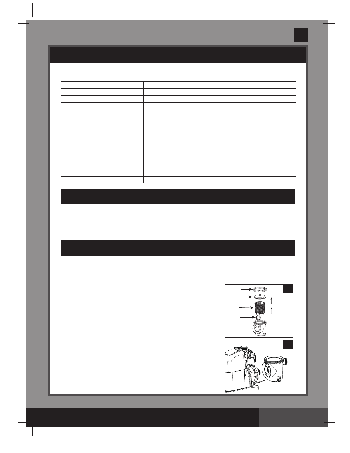
Motor pre-filtering assembly setup:
1.
Remove the sand filter and its accessories from the
packaging carefully and inspect for any visible damage.
2.
In a counter-clockwise motion unscrew the leaf trap cover
(14) from the pre-filter housing. Take out the basket (16) and
filter housing nut
(17) (see drawing 10).
3.
Connect the pre-filter housing to the motor water inlet.
Note: Align the connector in the pre-filter housing with the
water inlet on the motor
(see drawing 11).
10
11
14
17
16
40
Model: ECO20220/ECO20230 ECO15220/ECO15230
Wattage: 770 W 470 W
Ideal Salt Level: 3000 ppm (parts per million) 3000 ppm
Maximum Sanitizer Output/hour: 11 grams/hour 7 grams/hour
E.C.O. Cell Output Current: 800mA 500mA
Maximum working pressure:
2 bar (30 psi) 2 bar (30 psi)
Effective filtering area: 0.13 m
2
(1.44 ft2) 0.1 m2 (1.1 ft2)
Maximum Flow Rate: 8140 liters/hour
(2150 gallons/hour)
6055 liters/hour
(1600 gallons/hour)
Recommended filtering
media quantity:
No. 20 silica sand 45 Kg
(100 Lbs) or glass sand 32 Kg
(70 Lbs).
No. 20 silica sand 25 Kg
(55 Lbs) or glass sand 18 Kg
(40 Lbs).
Recommended filtering
media (Not included) :
No. 20 silica sand or glass sand. Particle size range 0.45 to 0.85
mm (0.018 to 0.033 inches). Uniformity Coefficient less than 1.75.
Limited Warranty: see “Limited Warranty”
HOW THE ELECTROCATALYTIC OXIDATION WORKS
The Electrocatalytic Oxidation (E.C.O.) is an Advanced Oxidation Processes (AOPs). When direct
current is applied to the electrocatalytic oxidation electrodes, water will be discharged to generate
“hydroxyl radicals”. The hydroxyl radical is a powerful oxidant, which oxidizes organic
contaminants, and destroys bacteria and algae. Hydroxyl radicals in combination with free
available chlorine provide the strongest and safest pool water sanitation.
Page 9
261A
SAVE THESE INSTRUCTIONS
(261IO) Sand Filter Pump & Saltwater System with Electrocatalysis Oxidation (14” & 16”) ENGLISH 7.5” X 10.3” PANTONE 295U 08/04/2014
English
Page 9
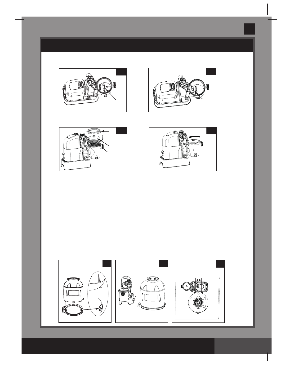
4.
In a clockwise motion screw filter housing nut (17) onto the motor water inlet (See
drawings 12.1 & 12.2)
.
5.
Replace the basket (16) and leaf trap cover (14) back to the pre-filter housing (See
drawings 13.1 & 13.2)
.
SETUP INSTRUCTIONS (continued)
13.2
14.1
14.2
14.3
12.2
12.1
17
17
13.1
16
14
40
115 mm
Sand tank installation:
1.
Place the tank support base at the selected location.
2.
Place the tank on the tank support base (See drawing 14.1).
3. Connect the motor pre-filtering assembly unit to the tank support base
(See drawing 14.2)
.
NOTE: Ensure the pre-filter housing water inlet hose connection is facing towards the pool.
IMPORTANT: Some countries, especially in the European community, require the
product to be secured to the ground or to a base in a permanent upright position.
Check your local authorities to determine if there is a regulation in your area
regarding above-the-ground swimming pool filter-pumps. If yes, then the product can
be mounted to a platform using the two holes located in the base. See drawing 14.3.
The product can be mounted on a cement base or onto a wooden platform to prevent
accidental falling over.
• Themountingholesare6.4mmindiameterandspaced115mmapart.
• Usetwoboltsandlocknutswithamaximumof6.4mmindiameter.
Page 10
261A
SAVE THESE INSTRUCTIONS
(261IO) Sand Filter Pump & Saltwater System with Electrocatalysis Oxidation (14” & 16”) ENGLISH 7.5” X 10.3” PANTONE 295U 08/04/2014
English
Page 10
SETUP INSTRUCTIONS (continued)
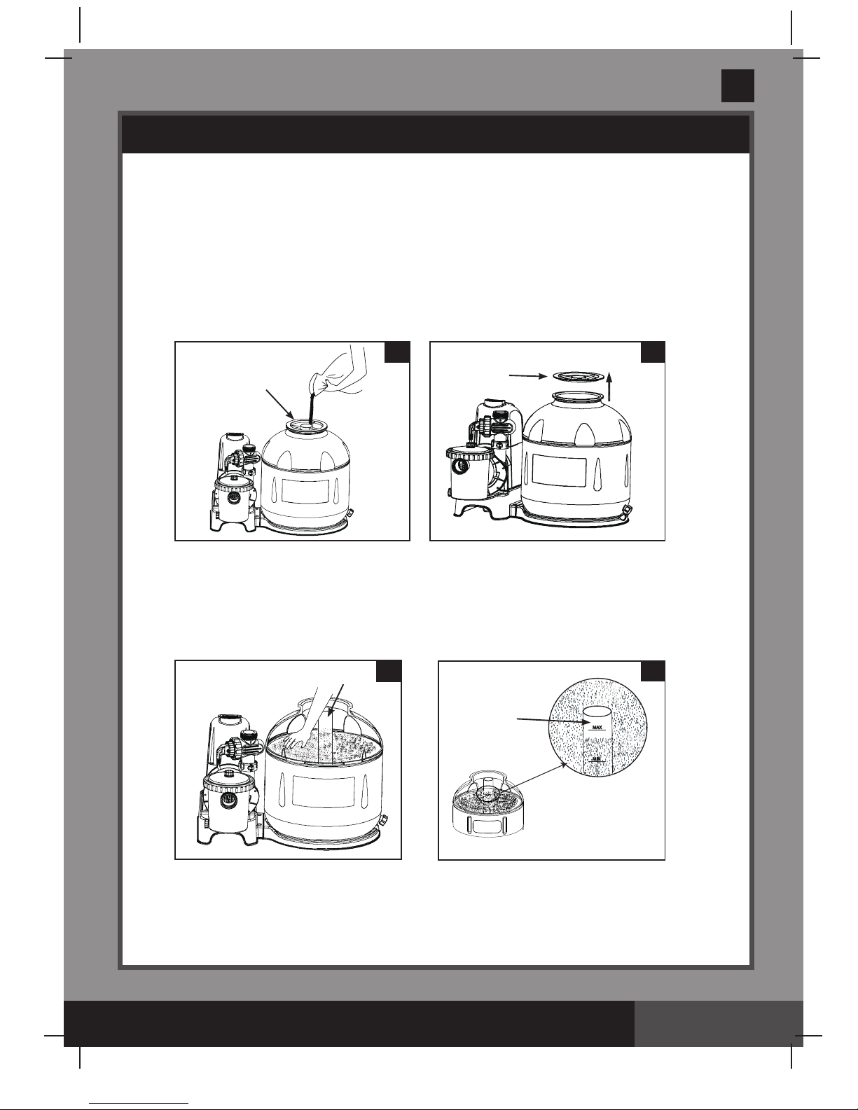
Sand loading:
IMPORTANT: Use No. 20 silica sand or glass sand with particle size range 0.45
to 0.85 mm (0.018 to 0.033 inches) and a Uniformity Coefficient less than 1.75.
NOTE: Before loading the tank with sand, ensure the center pipe hub assembly is
securely in place at the bottom of the tank, and vertically centered inside the tank.
1.
Place the sand shield
(7) over the top of the center pipe. Pour the sand into the tank at a
slow rate.
(see drawing 15).
2.
Fill the tank approximately half way, remove the sand shield (7). (see drawing 16).
3.
Evenly distribute the sand inside the tank, then fill the tank with some water to provide a
cushioning effect when the remaining sand is poured in. This prevents the center pipe hub
(8)
from excessive shock
(see drawing 17). Place the sand shield (7) back and continue to pour
the sand into the tank.
4.
Sand shall be filled between the “MAX” and “MIN” marked gauge on the center pipe. Evenly
spread and level out the sand by hand
(see drawings 17 & 18).
5.
Remove the sand shield
(7).
6.
Wash away all sand around the top edge of the tank.
15
7
16
7
MAX
MIN
MAX
MIN
18
8
MAX
MIN
17
8
Page 11
261A
SAVE THESE INSTRUCTIONS
(261IO) Sand Filter Pump & Saltwater System with Electrocatalysis Oxidation (14” & 16”) ENGLISH 7.5” X 10.3” PANTONE 295U 08/04/2014
English
Page 11
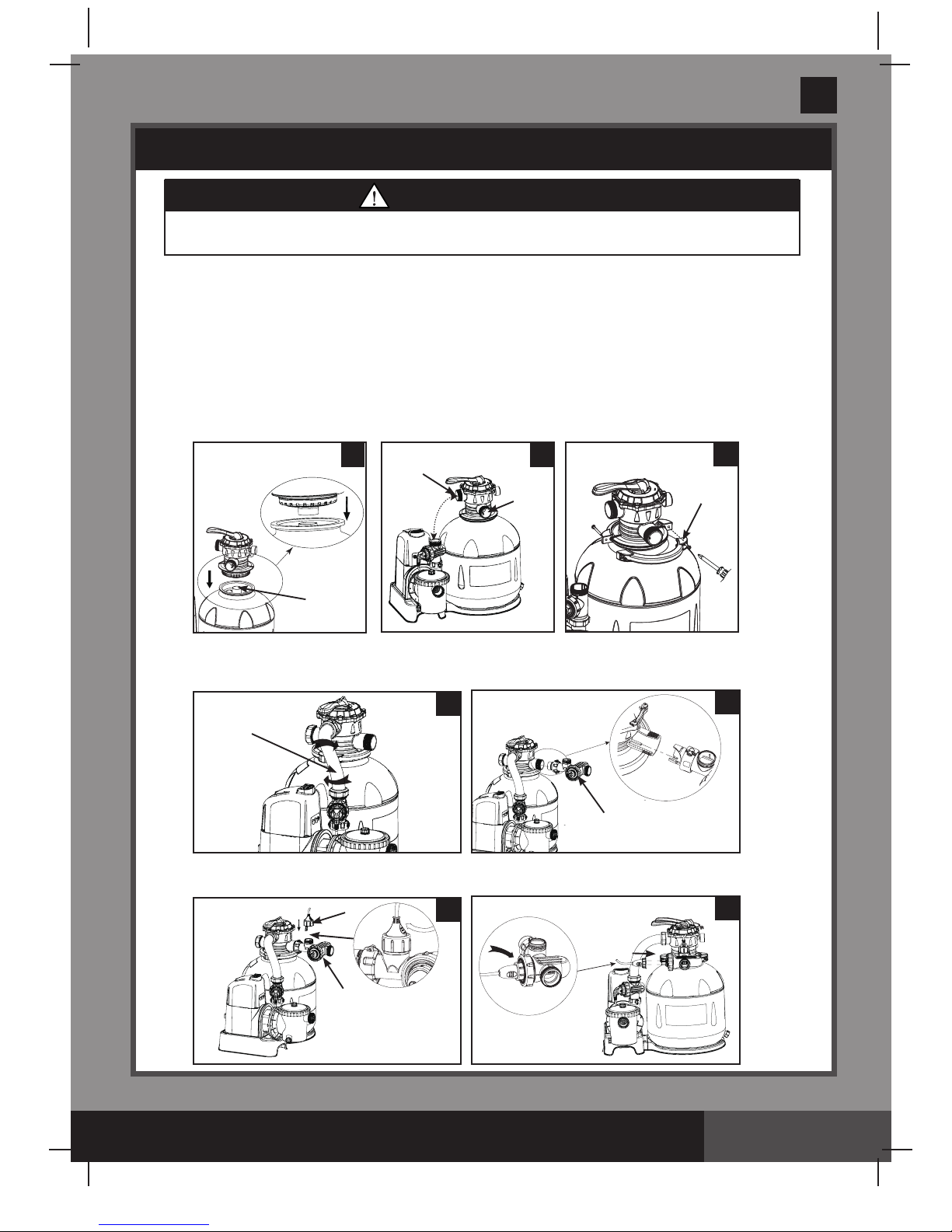
6-way valve installation:
1.
Lower the 6-way valve over the tank slowly, and ensure the bypass pipe protruding
underneath the 6-way valve fits securely into the center pipe hub
(8) top opening (see
drawing 19)
.
IMPORTANT: There are three hose connection ports on the 6-way valve, ensure the
outlet connection (from filter to the pool) on the valve is facing towards the pool, and
the inlet connection (from motor to valve) is aligned with the motor outlet (see
drawing 20).
2.
Remove the clamp bolt, and install the clamp around the tank and 6-way valve flanges, then
replace the clamp bolt and use a phillips screwdriver (not included) to tighten it.
(see
drawing 21)
.
SETUP INSTRUCTIONS (continued)
WARNING
Improper tank valve and clamp assembly could cause the valve and
clamp to blow off and cause serious injury, property damage or death.
3.
Connect the sand filter interconnecting hose (13) between the 6-way valve inlet and motor
outlet,
and insert the electrolytic cell (22) into the 6-way valve outlet. Hand tighten them
securely (
see drawings 22 and 23).
22
23
4.
Screw and tighten the flow sensor (21) to the electrolytic cell (22), then plug in the
electrolytic cell line cord and tighten the nut (
see drawings 24 and 25).
13
22
6
19
20
WATER
INLET
WATER
OUTLET
21
8
24
25
21
22
Page 12

261A
SAVE THESE INSTRUCTIONS
(261IO) Sand Filter Pump & Saltwater System with Electrocatalysis Oxidation (14” & 16”) ENGLISH 7.5” X 10.3” PANTONE 295U 08/04/2014
English
Page 12
SAND FILTER PUMP HOSE CONNECTION SETUP
The 6-way valve has three hose connection ports.
1.
Connect one hose
(12) end to the pre-filter inlet and the other end of the hose to the lower
plunger valve with the strainer. Ensure the hose nuts are securely tightened.
2.
Connect the second hose
(12) between the electrolytic cell outlet and the upper plunger valve
with the inlet-nozzle. Ensure the hose nuts are securely tighten.
3.
The third hose connection port (drain/waste outlet) on the 6-way valve shall be directed to
a proper draining receptacle using a hose or pipe (not provided). Remove the drain cap before
attaching the drain/waste hose or pipe.
4.
The sand filter pump is now ready to filter the pool.
WARNING
• Keepthisproductmorethan2mawayfromthepool.
• Keepthisproductmorethan3.5mawayfromthepool(forFranceonly).
• Keeptheplugofthisproductmorethan3.5mawayfromthepool.
• Positionthisproductawayfromthepool,soastopreventchildren
from climbing on it and accessing the pool.
(ILLUSTRATION NOT TO SCALE)
WATER LEVEL
>3.5M
>2M
6-WAY VALVE
ADJUSTABLE
POOL INLET
NOZZLE
THREADED
STRAINER
CONNECTOR
OUTSIDE
LINER WALL
PLUNGER
VALVE
TO
DRAIN
According to the International Standard, IEC 60364-7-702, on electrical installation of swimming
pools and other basins equipments, the following installation distances must be respected:
• The filter pump must be position more than 2m away from the pool walls.
• The power cord plug to the 220-240 volt electrical power source of the filter pump must be
position more than 3.5 m away from the pool walls.
Check your local authorities to determine the appropriate standard and requirements for “electrical
installation of swimming pools and basins equipments”. The following table is for reference only:
International
France
Germany
The Netherlands
Country/Region
Standard Number
IEC 60364-7-702
NF C 15-100-7-702
DIN VDE 0100-702
NEN 1010-702
Page 13

261A
SAVE THESE INSTRUCTIONS
(261IO) Sand Filter Pump & Saltwater System with Electrocatalysis Oxidation (14” & 16”) ENGLISH 7.5” X 10.3” PANTONE 295U 08/04/2014
English
Page 13
SAND FILTER PUMP HOSE CONNECTION SETUP (continued)
For INTEX pool size 16' and below:
1. In a counter-clockwise motion unscrew plunger valve union from the threaded strainer
connector
(33). Be careful not to lose the step rubber washer (30).
2. Grasp the plunger valve assembly. Make sure the step washer
(30) is in place. Connect
adaptor B
(35) to plunger valve union.
3. Remove wall plug and then insert the strainer
(36 & 38) into the lower position of protruding
hose connection, and the nozzle
(36 & 37) into the upper position of protruding hose
connection. Adaptor B
(35) fits over the strainer connection (36) inserted into the connection.
Tighten securely.
4. Remove the drain valve
(3) from the 6-way valve outlet and connect the hose to the outlet.
For NON-INTEX pool:
1.
Connect the hose
(12) to the pool inlet/outlet connection with a large hose clamp. Tighten
securely. Remove the drain valve
(3) from the 6-way valve outlet and connect the hose to
the outlet.
POOL
LARGE HOSE
CLAMP
12
3
POOL
36 & 37
3
36 & 38
Page 14

261A
SAVE THESE INSTRUCTIONS
(261IO) Sand Filter Pump & Saltwater System with Electrocatalysis Oxidation (14” & 16”) ENGLISH 7.5” X 10.3” PANTONE 295U 08/04/2014
English
Page 14
OPERATING INSTRUCTIONS
• Riskofelectricshock.Connectthisproductonlytoagroundingtypereceptacle
protected by a residual current device (RCD). Contact a qualified electrician if you
cannot verify that the receptacle is protected by a RCD. Use a qualified electrician to
install the RCD, which has a maximum rate of 30mA. Do not use a portable residual
current device (PRCD).
• To reduce the risk of electric shock, do not use extension cords, timers, plug adaptors
or converter plugs to connect unit to electric supply; provide a properly located outlet.
•
Do not attempt to plug in or unplug this product while standing in water or when your
hands are wet.
• Neveroperatethisproductabovethemaximumworkingpressurestatedonthefilter
tank.
• Alwaysswitchoffpumpbeforechangingthe6-wayvalveposition.
• Operatingthisproductwithoutwaterflowingthroughthesystemcancauseabuildup
of hazardous pressure which can result in an explosive situation, serious injury,
property damage or death.
• Nevertestthispumpwithcompressedair.Neveroperatethesystemwithwater
temperature above 35° C (95° F).
Valve Position Function Water Flow Direction
FILTER
(see drawing 26)
Normal filtration and regular
vacuuming of pool
From pump through filter media
to pool
BACKWASH
(see drawing 27)
Reverses water flow to clean filter
media
From pump through filter media
to valve waste/drain outlet
RINSE
(see drawing 28)
For initial startup cleaning of the sand, and
leveling the sand bed after backwashing
From pump through filter media
to valve waste/drain outlet
WASTE
(see drawing 29)
For vacuuming directly to waste,
lowering pool level or to drain the pool
From pump to valve waste/drain
outlet bypassing the filter media
RECIRCULATE
(see drawing 30)
For circulating water back to pool
without going through the filter media
From pump through valve to
pool bypassing the filter media
CLOSED
(see drawing 31)
Shuts off all flow to filter and pool
“Do not use this setting with pump running”
6-way valve positions and function:
WARNING
RETLIF
ESNIR
ETALUCRICER
ES
O
LC
ETSAW
ESN
IR
ETALUCRICER
HSAWKCAB
ESOLC
ETSAW
RETLIF
ESNIR
ETALUCRICER
HSAWKCAB
ETSAW
B
26
ESN
IR
ETALUCRICER
HSAWKCAB
ESOLC
ETSAW
RETLIF
ESNIR
ETALUCRICER
HSAWKCAB
ETSAW
27
RETLIF
ESNIR
ETALUCRICER
HSAWKCAB
ETSAW
28
Page 15

261A
SAVE THESE INSTRUCTIONS
(261IO) Sand Filter Pump & Saltwater System with Electrocatalysis Oxidation (14” & 16”) ENGLISH 7.5” X 10.3” PANTONE 295U 08/04/2014
English
Page 15
Initial startup and operation:
Before operating, be sure that:
• All the hoses have been connected and tightened securely, and correct amount of filter sand
have been loaded.
• The entire system is connected to a grounding type receptacle protected by a residual current
device (RCD).
OPERATING INSTRUCTIONS (continued)
CAUTION
The filter control valve has a closed position. The pump should
never be on when the valve is in the closed position. If the pump is
operated with the valve closed, and explosive situation could exist.
1.
Turn both plunger valve handles fully counter-clockwise until they stop. This opens the valves
to allow water to flow into the sand filter pump.
2.
Ensure the drain/waste outlet on the 6-way valve is not covered and directed to a proper
draining receptacle.
3.
Ensure the pump is off, depress the 6-way valve and turn
it to the “
BACKWASH” position (see drawings 27 & 32).
IMPORTANT: To prevent damage to the 6-way valve,
always depress the valve handle before turning.
Always switch off pump before changing the 6-way
valve position.
4.
Switch on the pump
(see drawing 33). Water is circulating
backward through the sand media and to waste/drain outlet.
Backwash until a clear flow of water is observed in the
waste/drain outlet or through the drain sediment window.
NOTE: The initial backwash of the filter is recommended to
remove any impurities or fine sand particles in the sand
media.
32
1
2
33
OFF
ON
RETLIF
ESNI
R
ETALUCRICER
ES
O
LC
ETSAW
ESN
IR
ETALUCRICER
HSAWKCAB
ESOLC
ETSAW
RETLIF
ESNIR
ETALUCRICER
HSAWKCAB
ETSAW
R
ETLIF
ESNIR
ER
HSAWKCAB
ESOLC
ETSAW
RETLIF
ESNIR
ETALUCRICER
HSAWKCAB
ESOLC
R
ETLIF
ETALUCRICER
HSAWKCAB
ESOLC
ETSAW
B
29
ESN
IR
ETALUCRICER
HSAWKCAB
ESOLC
ETSAW
RETLIF
ESNIR
ETALUCRICER
HSAWKCAB
ETSAW
RETLIF
ESNIR
ETALUCRICER
HSAWKCAB
ESOLC
R
ETLIF
ETALUCRICER
HSAWKCAB
ESOLC
ETSAW
30
RETLIF
ESNIR
ETALUCRICER
HSAWKCAB
ETSAW
R
ETLIF
ETALUCRICER
HSAWKCAB
ESOLC
ETSAW
31
Page 16

261A
SAVE THESE INSTRUCTIONS
(261IO) Sand Filter Pump & Saltwater System with Electrocatalysis Oxidation (14” & 16”) ENGLISH 7.5” X 10.3” PANTONE 295U 08/04/2014
English
Page 16
OPERATING INSTRUCTIONS (continued)
5.
Switch off the pump, change the 6-way valve to “RINSE” position
(see drawing 28).
6.
Switch on the pump and run the pump for about one minute to level out the sand bed after
backwashing the sand media.
7.
Switch off the pump, change the 6-way valve to “FILTER” position
(see drawing 26).
8.
Switch on the pump. The system is now operating in the normal filtering mode. Run the pump
until the desired pool water clearance is obtained and no more than 12 hours per day.
9.
Record the initial pressure gauge reading when the filter media is clean.
NOTE: During initial setup of the system, it may be necessary to backwash frequently due to
unusual heavy dirt present in the water and sand. After that, as the filter removes dirt and
impurities from the pool water, the accumulated dirt in the sand media will cause the pressure
to rise and the flow to diminish. If there is no vacuuming device attached to the system and
the pressure gauge reading is in the yellow zone it is time to backwash the sand media, see
“BACKWASH” under “initial startup and operation” section.
Vacuuming device (i.e. Intex auto pool cleaner) attached to the system may also cause the
flow to diminish and the pressure to rise. Remove any vacuuming device from the system and
check if the pressure gauge reading has dropped from the yellow zone to the green zone.
Page 17

261A
SAVE THESE INSTRUCTIONS
(261IO) Sand Filter Pump & Saltwater System with Electrocatalysis Oxidation (14” & 16”) ENGLISH 7.5” X 10.3” PANTONE 295U 08/04/2014
English
Page 17
SALTWATER SYSTEM OPERATION
1. Start up the unit:
Plug the power cord into the electrical outlet and test the RCD
(circuit breaker). Switch on the unit. With the Filter Pump turned “ON”
and operating. Flashing code“00” appears on the electronic control
station’s LED, indicating that the unit is ready to be programmed.
2. Set operating hours for Saltwater System:
With code “00” flashing, press button to set the
desired operating hours. See the “Operating Time Table”
for the required operating hours related to each pool size.
Pressing will increase the time from 01 to 12 hours
maximum. If you have selected too many hours keep
pressing to repeat the cycle. The built-in timer will
now activate your Saltwater System, at the same time
each day, for the number of hours you have set.
NOTE:
The Saltwater System will not operate if the filter
pump is not operating.
3. Lock keypad controls:
With the desired hour value showing, press button until you hear a
“beep”. The green “WORKING” indicator on the control panel will light up
within a few seconds to indicate that the saltwater system has started
sanitizer production. Locking the control buttons into this setting prevents
unauthorized changing of the operating cycle.
NOTE:
If you forget to lock the keypad controls, the system will
automatically lock it and start working 1 minute later.
4. Readjust operating time if necessary:
The operating hours can be re-adjusted if necessary. Press button
until you hear a “beep” to unlock the keypad and the current
programmed time will flash. Repeat steps 2 to 3.
(1 to 12 hours max per cycle)
Page 18

261A
SAVE THESE INSTRUCTIONS
(261IO) Sand Filter Pump & Saltwater System with Electrocatalysis Oxidation (14” & 16”) ENGLISH 7.5” X 10.3” PANTONE 295U 08/04/2014
English
Page 18
SALTWATER SYSTEM OPERATION (continued)
5. Boost cycle
•
First time installation, press and hold “BOOST”
button for 5 seconds until the indicator lights up and the
LED display “80”. This indicates that the saltwater
system has started E.C.O. and more chlorine sanitizer
production. You can press and hold the “BOOST” button for
another 5 seconds until the indicator is off, which will cancel
the Boost cycle.
• The boost operating hours is 8 times the amount of time programmed into the system, i.e. if your
saltwater system operating time is 2 hours, the boost procedure will run 8 x 2 = 16 hours. After
boost procedure has been completed, the system will automatically switch to the normal
working mode.
•
After a heavy rain or if the pool is dirty, press the “BOOST” button to shock the pool again.
6.
Stand-by/power saving mode:
•
When the cycle ends, the green “SLEEP” indicator on the control panel lights
up and the LED display flashes “93”. The system is now in Stand-By mode.
After a while, it shuts down and sets itself in a Power Saving mode. The
system will automatically turn itself back on in 24 hours, starting its daily
cycle of chlorine production.
•
The “SLEEP” indicator stays on, while the system is in the Power Saving
mode. The LED display however, goes blank after 5 minutes. Press any
button ( or ) to view the last LED code.
7. Running the pump alone without the Saltwater System:
To run the pump alone without the Saltwater System function, press and
hold both ( ) and ( ) buttons for 5 seconds until you hear a “beep” and
the LED display shows “FP”. The pump is now operating alone. To stop the
pump, manually turn the switch OFF.
NOTE: The pump cannot be operated
alone under an automatic timer mode.
To bring back the initial automatic operating cycle setting
of the Saltwater System:
a) If the LED display shows “FP”, press the button and the operating
hours set previously will begin flashing, press the button again or
simply wait 1 minute, and the LED will stay illuminated. The Saltwater
System cycle repeats again.
b) If the unit is OFF, turn the switch ON, the LED display shows “FP”,
press the button and the operating hours set previously will begin
flashing, press the button again or simply wait 1 minute, and the
LED will stay illuminated. The Saltwater System cycle repeats again.
Page 19

261A
SAVE THESE INSTRUCTIONS
(261IO) Sand Filter Pump & Saltwater System with Electrocatalysis Oxidation (14” & 16”) ENGLISH 7.5” X 10.3” PANTONE 295U 08/04/2014
English
Page 19
LED CODE CHART
LED Reading Definitions
FP Filter Pump Working Mode
80 Boost Mode
00 Stand-By Mode (Start-up)
01 Minimum Operating Hour (1 hour remaining)
02 Operating Hours (2 hours remaining)
03 Operating Hours (3 hours remaining)
04 Operating Hours (4 hours remaining)
05 Operating Hours (5 hours remaining)
06 Operating Hours (6 hours remaining)
07 Operating Hours (7 hours remaining)
08 Operating Hours (8 hours remaining)
09 Operating Hours (9 hours remaining)
10 Operating Hours (10 hours remaining)
11 Operating Hours (11 hours remaining)
12 Maximum Operating Hours (12 hours remaining)
90 Alarm Code (Low Pump Flow / No Flow)
91 Alarm Code (Low Salt Level)
92 Alarm Code (High Salt Level)
93 Stand-By Mode (Operating Process finished)
“BLANK” No Power or “Power Saving Mode” waiting to start next
Saltwater System cycle.
Page 20

261A
SAVE THESE INSTRUCTIONS
(261IO) Sand Filter Pump & Saltwater System with Electrocatalysis Oxidation (14” & 16”) ENGLISH 7.5” X 10.3” PANTONE 295U 08/04/2014
English
Page 20
SALT & POOL WATER VOLUMES
• Whichkindofsalttouse:
Use only Sodium Chloride Salts
Use only sodium chloride (NaCl) salt that is at least 99.8% pure. It is also acceptable to use
water conditioning salt pellets (the compressed forms of evaporated salt). However, it will take
a longer time for them to dissolve. Do not use iodized or yellow (yellow prussiate of soda)
colored salt. Salt is added to the pool water and the electrolytic cell uses the salt to create the
sanitizer. So, the purer the salt the better the performance of the electrolytic cell.
• OptimumSaltLevels
The ideal salt level in the pool water is between 2500-3500 ppm (parts per million). The optimal
level is 3000 ppm.
A too low salt level will reduce the efficiency of the saltwater system and result in low sanitizer
production. A high salt level may generate a salty taste to the pool water (this may occur at a salt
level above 3500-4000ppm). Too high of a salt level may damage the power supply and cause
corrosion to pool metal fixtures and accessories. The Salt Table page of this manual, shows the
correct dosage of salt needed. The salt in the pool is constantly recycled. Salt loss occurs only
when pool water is physically removed from the pool. Salt is not lost due to evaporation.
• AddingSalt
1
. Switch on the unit, then press and hold both and button for 5 seconds, the LED
flashes “FP”. The unit is now in a Filter pump working mode and switch the filter pump on to
start the water circulation.
2
. Keep the Saltwater System turned off.
3
. Determine the amount of salt to be added (see “Salt Table”).
4
. Evenly spread the proper amount of salt around the inside perimeter of the pool.
5
. Avoid clogging the filter by not adding salt through the skimmer.
6
. Brush the pool bottom to speed up the dissolving process. Do not allow salt to pile up on the
bottom of the pool. Run the filter pump 24 consecutive hours to thoroughly dissolve the salt.
7
. After 24 hours and if all the salt is dissolved, turn on the Saltwater System, press button
until you hear a “beep”, code “00” flashing (see “System Operation” section steps 2 to 4) and
set the saltwater pool system to desired operating time (see “Operating Time Table”).
• RemovingSalt
If too much salt has been added, the unit will beep and display “Code 92” (see “Alarm Codes”).
You will need to lower the salt concentration. The only way to do so, is to partially drain the pool
and refill it with fresh water. Drain and refill approximately 20% of the pool’s water until the “Code
92” disappears.
• PoolVolumeCalculation
Rectangular Length x Width x Average Depth x 7.5 Length x Width x Average Depth
Circular Length x Width x Average Depth x 5.9 Length x Width x Average Depth x 0.79
Oval Length x Width x Average Depth x 6.0 Length x Width x Average Depth x 0.80
Types of Pool
Gallons
(pool size in feet)
Cubic Meters
(pool size in meters)
Page 21

261A
SAVE THESE INSTRUCTIONS
(261IO) Sand Filter Pump & Saltwater System with Electrocatalysis Oxidation (14” & 16”) ENGLISH 7.5” X 10.3” PANTONE 295U 08/04/2014
English
Page 21
INTEX POOLS SALT TABLE
This table shows the dosage of salt needed to achieve and maintain the optimal 3000 ppm salt
level.
Pool Size
Water Capacity
(Calculated at 90% for
Frame Pool and 80% for
Easy Set & Oval Pool)
Salt Needed for Startup
3.0g/L (3000ppm)
Salt Needed when
Low Salt Detected
(CODE “91”)
(Gals)
(Liters)
ECO20220/
ECO20230
ECO15220/
ECO15230
ECO20220/
ECO20230
ECO15220/
ECO15230
(Lbs) (Kgs) (Lbs) (Kgs) (Lbs) (Kgs) (Lbs) (Kgs)
INTEX ABOVE GROUND POOLS (AGP’s)
EASY SET®
POOL
15' x 33" (457cm x 84cm)
2587 9792
- -
65 30
- -
20 10
15' x 36" (457cm x 91cm)
2822 10681
- -
65 30
- -
20 10
15' x 42" (457cm x 107cm)
3284 12430
- -
80 35
- -
20 10
15' x 48" (457cm x 122cm)
3736 14141
- -
95 45
- -
25 10
16' x 42" (488cm x 107cm)
3754 14209
- -
95 45
- -
25 10
16' x 48" (488cm x 122cm)
4273 16173
- -
110 50
- -
30 15
16' x 52" (488cm x 132cm)
4614 17464
- -
115 50
- -
30 15
18' x 42" (549cm x 107cm)
4786 18115 120 55 120 55 30 15 30 15
18' x 48" (549cm x 122cm)
5455 20647 135 60 135 60 35 15 35 15
CIRCULAR
METAL
FRAME POOL
15' x 36" (457cm x 91cm)
3282 12422
- -
80 35
- -
20 10
15' x 42" (457cm x 107cm)
3861 14614
- -
100 45
- -
25 10
15' x 48" (457cm x 122cm)
4440 16805
- -
110 50
- -
30 15
16' x 48" (488cm x 122cm)
5061 19156
- -
125 55
- -
35 15
18' x 48" (549cm x 122cm)
6423 24311 160 75 160 75 40 20 40 20
21' x 52" (640cm x 132cm)
9533 36082 240 110 - - 60 30 - -
24' x 52" (732cm x 132cm)
12481 47241 310 140 - - 80 35 - -
ULTRA FRAME
POOL
16’ x 48” (488cm x 122cm)
5061 19156
- -
125 55
- -
35 15
18’ x 48” (549cm x 122cm)
6423 24311 160 75 160 75 40 20 40 20
18' x 52" (549cm x 132cm)
6981 26423 175 80 175 80 45 20 45 20
20’ x 48” (610cm x 122cm)
7947 30079 210 90 210 90 50 25 50 25
22’ x 52” (671cm x 132cm)
10472 39637 260 120 - - 65 30 - -
24’ x 52” (732cm x 132cm)
12481 47241 310 140 - - 80 35 - -
26 ’x 52” (792cm x 132cm)
14667 55515 365 165 - - 90 40 - -
SEQUOIA SPIRIT™
POOL SET
15'8" x 49" (478cm x 124cm)
4440 16805 110 50 110 50 30 15 30 15
16’8” x 49” (508cm x 124cm)
5061 19156 125 55 125 55 35 15 35 15
18'8" x 53" (569cm x 135cm)
6981 26423 175 80 175 80 45 20 45 20
OVAL FRAME
POOL
10’ x 18’ x 42” (305cm x 549cm x 107cm)
2885 10920 70 30 70 30 20 10 20 10
12' x 20' x 48" (366cm x 610cm x 122cm)
4393 16628 110 50 110 50 30 15 30 15
RECT. ULTRA
FRAME POOL
9’ x 15’ x 48” (274cm x 457cm x 122cm)
3484 13187
- -
90 40
- -
25 10
9' x 18' x 52" (274cm x 549cm x 132cm)
4545 17203 115 50 115 50 30 15 30 15
10’ x 20’ x 52” (305cm x 610cm x 132cm)
5835 22085 145 65 145 65 40 20 40 20
12' x 24' x 52" (366cm x 732cm x 132cm)
8403 31805 210 95 210 95 55 25 55 25
16' x 32' x 52" (488cm x975cm x 132cm)
14364 54368 360 165 - - 90 40 - -
Page 22

261A
SAVE THESE INSTRUCTIONS
(261IO) Sand Filter Pump & Saltwater System with Electrocatalysis Oxidation (14” & 16”) ENGLISH 7.5” X 10.3” PANTONE 295U 08/04/2014
English
Page 22
INTEX POOLS CYANURIC ACID TABLE
Cyanuric acid is a chemical that reduces the loss of chlorine in water due to ultraviolet rays. To
maintain maximum performance, we recommend that the cyanuric acid level be maintained at
approximately 1% of the salt, i.e. 100 Lbs (45 Kgs) salt x1% = 1 Lbs (0.45 Kgs) cyanuric acid.
If the pool water is dirty, filthy or grimy, DO NOT add chlorine stabilizer (cyanuric acid) as this
will slowdown the sanitation time of the device. Under this condition you must BOOST your
pool water, refer to BOOST cycle steps. Once the pool water has been restored to clear and
clean conditions you may add cyanuric acid.
Pool Size
Water Capacity (Calculated at
90% for Frame Pool and 80% for
Easy Set & Oval Pool)
Cyanuric Acid Needed for Startup
0.03g/L (30ppm)
(Gals)
(Liters)
ECO20220/ECO20230 ECO15220/ECO15230
(Lbs) (Kgs) (Lbs) (Kgs)
INTEX ABOVE GROUND POOLS (AGP’s)
EASY SET®
POOL
15' x 33" (457cm x 84cm)
2587 9792
- -
0.6 0.3
15' x 36" (457cm x 91cm)
2822 10681
- -
0.7 0.3
15' x 42" (457cm x 107cm)
3284 12430
- -
0.8 0.4
15' x 48" (457cm x 122cm)
3736 14141
- -
0.9 0.4
16' x 42" (488cm x 107cm)
3754 14209
- -
0.9 0.4
16' x 48" (488cm x 122cm)
4273 16173
- -
1.1 0.5
16' x 52" (488cm x 132cm)
4614 17464
- -
1.2 0.5
18' x 42" (549cm x 107cm)
4786 18115 1.2 0.5 1.2 0.5
18' x 48" (549cm x 122cm)
5455 20647 1.4 0.6 1.4 0.6
CIRCULAR
METAL
FRAME POOL
15' x 36" (457cm x 91cm)
3282 12422
- -
0.8 0.4
15' x 42" (457cm x 107cm)
3861 14614
- -
1.0 0.4
15' x 48" (457cm x 122cm)
4440 16805
- -
1.1 0.5
16' x 48" (488cm x 122cm)
5061 19156
- -
1.3 0.6
18' x 48" (549cm x 122cm)
6423 24311 1.6 0.7 1.6 0.7
21' x 52" (640cm x 132cm)
9533 36082 2.4 1.1 - -
24' x 52" (732cm x 132cm)
12481 47241 3.1 1.4 - -
ULTRA FRAME
POOL
16’ x 48” (488cm x 122cm)
5061 19156
- -
1.3 0.6
18’ x 48” (549cm x 122cm)
6423 24311 1.6 0.7 1.6 0.7
18' x 52" (549cm x 132cm)
6981 26423 1.7 0.8 1.7 0.8
20’ x 48” (610cm x 122cm)
7947 30079 2.0 0.9 2.0 0.9
22’ x 52” (671cm x 132cm)
10472 39637 2.6 1.2 - -
24’ x 52” (732cm x 132cm)
12481 47241 3.1 1.4 - -
26 ’x 52” (792cm x 132cm)
14667 55515 3.7 1.7 - -
SEQUOIA SPIRIT™
POOL SET
15'8" x 49" (478cm x 124cm)
4440 16805 1.1 0.5 1.1 0.5
16’8” x 49” (508cm x 124cm)
5061 19156 1.3 0.6 1.3 0.6
18'8" x 53" (569cm x 135cm)
6981 26423 1.7 0.8 1.7 0.8
OVAL FRAME
POOL
10’ x 18’ x 42” (305cm x 549cm x 107cm)
2885 10920 0.7 0.3 0.7 0.3
12' x 20' x 48" (366cm x 610cm x 122cm)
4393 16628 1.1 0.5 1.1 0.5
RECT. ULTRA
FRAME POOL
9’ x 15’ x 48” (274cm x 457cm x 122cm)
3484 13187
- -
0.9 0.4
9' x 18' x 52" (274cm x 549cm x 132cm)
4545 17203 1.1 0.5 1.1 0.5
10’ x 20’ x 52” (305cm x 610cm x 132cm)
5835 22085 1.5 0.7 1.5 0.7
12' x 24' x 52" (366cm x 732cm x 132cm)
8403 31805 2.1 1.0 2.1 1.0
16' x 32' x 52" (488cm x975cm x 132cm)
14364 54368 3.6 1.6 - -
Page 23

261A
SAVE THESE INSTRUCTIONS
(261IO) Sand Filter Pump & Saltwater System with Electrocatalysis Oxidation (14” & 16”) ENGLISH 7.5” X 10.3” PANTONE 295U 08/04/2014
English
Page 23
INTEX POOLS OPERATING TIME TABLE (WITH CYANURIC ACID)
Pool Size
Water Capacity
(Calculated at 90% for
Frame Pool and 80% for
Easy Set & Oval Pool)
Operating Time (hours)
at different ambient/air
temperatures
(Gals)
(Liters)
ECO20220/ECO20230
ECO15220/ECO15230
10 - 19°C
(50 - 66°F)
20 - 28°C
(68 - 82°F)
29 - 36°C
(84 - 97°F)
10 - 19°C
(50 - 66°F)
20 - 28°C
(68 - 82°F)
29 - 36°C
(84 - 97°F)
INTEX ABOVE GROUND POOLS (AGP’s)
EASY SET®
POOL
15' x 33" (457cm x 84cm)
2587 9792
- - -
2 2 3
15' x 36" (457cm x 91cm)
2822 10681
- - -
2 2 3
15' x 42" (457cm x 107cm)
3284 12430
- - -
2 3 4
15' x 48" (457cm x 122cm)
3736 14141
- - -
3 3 4
16' x 42" (488cm x 107cm)
3754 14209
- - -
3 3 4
16' x 48" (488cm x 122cm)
4273 16173
- - -
3 3 4
16' x 52" (488cm x 132cm)
4614 17464
- - -
3 4 5
18' x 42" (549cm x 107cm)
4786 18115 2 2 3 3 4 5
18' x 48" (549cm x 122cm)
5455 20647 2 3 4 4 4 5
CIRCULAR
METAL
FRAME POOL
15' x 36" (457cm x 91cm)
3282 12422
- - -
2 3 4
15' x 42" (457cm x 107cm)
3861 14614
- - -
3 3 4
15' x 48" (457cm x 122cm)
4440 16805
- - -
3 4 5
16' x 48" (488cm x 122cm)
5061 19156
- - -
4 4 5
18' x 48" (549cm x 122cm)
6423 24311 3 3 4 5 5 6
21' x 52" (640cm x 132cm)
9533 36082 4 5 6 - - -
24' x 52" (732cm x 132cm)
12481 47241 6 6 7 - - -
ULTRA FRAME
POOL
16’ x 48” (488cm x 122cm)
5061 19156
- - -
4 4 5
18’ x 48” (549cm x 122cm)
6423 24311 3 3 4 5 5 6
18' x 52" (549cm x 132cm)
6981 26423 3 4 5 5 6 7
20’ x 48” (610cm x 122cm)
7947 30079 4 4 5 6 6 7
22’ x 52” (671cm x 132cm)
10472 39637 5 5 6 - - -
24’ x 52” (732cm x 132cm)
12481 47241 6 6 7 - - -
26 ’x 52” (792cm x 132cm)
14667 55515 7 8 8 - - -
SEQUOIA SPIRIT™
POOL SET
15'8" x 49" (478cm x 124cm)
4440 16805 2 2 3 3 4 5
16’8” x 49” (508cm x 124cm)
5061 19156 2 3 4 4 4 5
18'8" x 53" (569cm x 135cm)
6981 26423 3 4 5 5 6 7
OVAL FRAME
POOL
10’ x 18’ x 42” (305cm x 549cm x 107cm)
2885 10920 1 1 2 2 2 3
12' x 20' x 48" (366cm x 610cm x 122cm)
4393 16628 2 2 3 3 4 5
RECT. ULTRA
FRAME POOL
9’ x 15’ x 48” (274cm x 457cm x 122cm)
3484 13187
- - -
2 3 4
9' x 18' x 52" (274cm x 549cm x 132cm)
4545 17203 2 2 3 3 4 5
10’ x 20’ x 52” (305cm x 610cm x 132cm)
5835 22085 3 3 4 4 5 6
12' x 24' x 52" (366cm x 732cm x 132cm)
8403 31805 4 4 5 6 7 8
16' x 32' x 52" (488cm x975cm x 132cm)
14364 54368 7 7 8 - - -
Page 24

261A
SAVE THESE INSTRUCTIONS
(261IO) Sand Filter Pump & Saltwater System with Electrocatalysis Oxidation (14” & 16”) ENGLISH 7.5” X 10.3” PANTONE 295U 08/04/2014
English
Page 24
SALT TABLE FOR COMMON NON-INTEX POOLS
SALT CALCULATION FORMULA FOR ALL POOLS
Salt Needed for Startup
(Lbs)
Salt Needed for Startup
(Kgs)
Salt Needed when
Low Salt Detected (Lbs)
Salt Needed when
Low Salt Detected (Kgs)
Water Capacity (Gals) x 0.025
Water Capacity (Liters) x 0.003
Water Capacity (Gals) x 0.0067 Water Capacity (Liters) x 0.0008
Water Capacity
Salt Needed for Startup
Salt Needed when Low Salt
Detected (CODE “91”)
(Gals) (Liters)
ECO20220/ECO20230 ECO15220/ECO15230 ECO20220/ECO20230 ECO15220/ECO15230
(Lbs) (Kgs) (Lbs) (Kgs) (Lbs) (Kgs) (Lbs) (Kgs)
2000 7500 50 20 50 20 10 5 10 5
4000 15000 100 45 100 45 25 10 25 10
6000 22500 150 65 150 65 40 20 40 20
8000 30000 200 90 - - 55 25 - -
8500 32000 - - 210 95 - - 55 25
10000 37500 250 110 - - 70 30 - 12000 45500 300 135 - - 80 35 - 14000 53000 350 160 - - 95 45 - -
OPERATING TIME TABLE FOR COMMON NON-INTEX POOLS
Water Capacity
Operating Time (hours)
at different ambient/air temperatures
(Gals) (Liters)
ECO20220/ECO20230 ECO15220/ECO15230
10 - 19°C
(50 - 66°F)
20 - 28°C
(68 - 82°F)
29 - 36°C
(84 - 97°F)
10 - 19°C
(50 - 66°F)
20 - 28°C
(68 - 82°F)
29 - 36°C
(84 - 97°F)
2000 7500 1 1 1 1 2 3
4000 15000 2 2 3 3 3 4
6000 22500 3 3 4 4 5 6
8000 30000 4 4 5 - - -
8500 32000 - - - 6 7 8
10000 37500 5 5 6 - - 12000 45500 6 6 7 - - 14000 53000 7 7 8 - - -
CYANURIC ACID TABLE FOR COMMON NON-INTEX POOLS
Water Capacity
Cyanuric Acid Needed for Startup 0.03g/L (30ppm)
(Gals) (Liters)
ECO20220/ECO20230 ECO15220/ECO15230
(Lbs) (Kgs) (Lbs) (Kgs)
2000 7500 0.5 0.23 0.5 0.23
4000 15000 1.0 0.45 1.0 0.45
6000 22500 1.5 0.68 1.5 0.68
8000 30000 2.0 0.90 - -
8500 32000 - - 2.13 0.96
10000 37500 2.5 1.13 - 12000 45500 3.0 1.37 - 14000 53000 3.5 1.59 - -
Page 25

261A
SAVE THESE INSTRUCTIONS
(261IO) Sand Filter Pump & Saltwater System with Electrocatalysis Oxidation (14” & 16”) ENGLISH 7.5” X 10.3” PANTONE 295U 08/04/2014
English
Page 25
MOTOR PRE-FILTER CLEANING AND MAINTENANCE
1.
Make sure the filter pump is switched off, then disconnect the power cord from the electrical
outlet.
2.
Turn both plunger valve handles fully clockwise until they stop. This closes the valve, prevents
the water from flowing out of the pool.
3.
Release the pressure first by opening the sediment
release valve
(19) located on the lower side of the
pre-filter housing
(see drawing 34).
4.
In a counter-clockwise motion unscrew the leaf trap
cover
(14), then remove the basket (16) and leaf trap
o-ring
(15) from the pre-filter housing (see drawing 35).
5.
Empty and flush the basket using a garden hose, may
use a plastic brush to remove deposits from the basket.
Do not use metal brush.
6.
Clean and rinse the inside of the pre-filter housing and
the leaf trap O-ring with a garden hose.
7.
Reinstall the leaf trap O-ring, basket and leaf trap cover
to the pre-filter housing.
8.
Close the sediment release valve
(19) back.
FLOW SENSOR CLEANING
1
. In a counter-clockwise motion unscrew the collar of the flow sensor
(21) and remove it from
the electrolytic cell conduit
(22). See “Part Reference”.
2
. If deposits and debris are seen on the surface of the flow sensor, then use a garden hose
to wash it off.
3
. If flushing with water does not remove the deposits, use a plastic brush to clean the surface
and the hinge if necessary. Do not use a metal brush.
4
. After the flow sensor has been inspected and cleaned, align the locator notch on the flow
sensor to the connection ridge in the conduit. Now turn the collar in a clockwise motion,
tightening the sensor back into its position. Do not overtighten.
Connection Ridge
Locator Notch
Hinge
35
14
16
15
1
2
34
19
40
Page 26

261A
SAVE THESE INSTRUCTIONS
(261IO) Sand Filter Pump & Saltwater System with Electrocatalysis Oxidation (14” & 16”) ENGLISH 7.5” X 10.3” PANTONE 295U 08/04/2014
English
Page 26
ELECTROLYTIC CELL CLEANING
E.C.O. ELECTRODE CLEANING
The titanium electrode and E.C.O. electrodes have a self cleaning function incorporated into the
electronic control’s programming. In most cases this self cleaning action will keep the electrodes
working at optimum efficiency. If the pool water is hard (high mineral content) the electrodes may
require periodic manual cleaning. To maintain maximum performance, we recommend that you
open and visually inspect the titanium and E.C.O. electrodes (4 & 5) monthly.
The following steps are some instructions on how to clean your cell.
1. Switch off the unit, unplug the power cord from the electrical socket.
2
. Disconnect the hose
(12) from the electrolytic cell (22) outlet and cover the outlet with the
drain outlet cover
(3) from the 6-way valve (see drawings 36 and 37).
3.
Remove the electrolytic cell from the 6-way valve outlet by unscrewing the electrolytic cell
(22)
collar
(see drawing 38).
4.
Pour kitchen grade vinegar into the cell to immerse the titanium plates
(see drawing 39).
Soak for about 1 hour and then flush with a high-pressure garden hose.
5.
Reverse steps 2 to 4 to reconnect the electrolytic cell.
1
. Switch off the unit, unplug the power cord from the electrical socket.
2
. In a counter-clockwise motion, unscrew the electrical plug collar from the E.C.O. electrode
cell, and remove the electrical plug from electrode cell (see drawings 40 and 41).
3.
Unscrew the E.C.O. electrode cell collar, then remove the electrode cell and place it on a
bucket.
4.
Pour kitchen grade vinegar into the bucket until the E.C.O. electrode cell is immersed (see
drawing 43)
. Soak for 1 hour and then flush with a high-pressure garden hose.
5. Reverse steps 2 to 4 to reconnect the E.C.O. electrode cell.
41
42
40
43
24
37
36
39
3
22
38
22
Page 27

261A
SAVE THESE INSTRUCTIONS
(261IO) Sand Filter Pump & Saltwater System with Electrocatalysis Oxidation (14” & 16”) ENGLISH 7.5” X 10.3” PANTONE 295U 08/04/2014
English
Page 27
MAINTENANCE (continued)
POOL CARE & CHEMICALS
• All pools require care to keep the water clear and hygienically clean. With proper chemical
control, your filter will help attain this objective. Consult your pool supply dealer for
instructions regarding the proper use of chlorine, algaecide and other chemical agents
required for sparkling clear water.
• Keep pool chemicals away from children.
• Do not replenish chemicals in pool while pool is occupied. Skin or eye irritations could
occur.
• Daily pH checking and chemical treatment of the water is very important and cannot be
overemphasized. Maintenance of proper pH levels are required when filling the pool as well
as during the season. Consult your local swimming pool supply store for instructions.
• The season's first filling of the pool may have brackish water requiring extra water additives
and extra filtering time. Do not allow swimming in pool until the pH level is balanced. Consult
your local swimming pool supply store for instructions.
• Chlorinated water may damage lawns, gardens or shrubbery as children play in the pool
and splash water outside the pool. Lawn areas underneath the pool liner will be destroyed.
Note that some types of grass may grow through the liner.
• Filter run time depends on pool size, weather and usage level. Experiment with various run
times so as to produce clean clear water.
The Test Strips can test the “Free Chlorine”, “pH”, “Calcium Hardness” and “Total Alkalinity”
levels at the same time. We recommend that you test the water chemistry weekly, and maintain
the chlorine concentration at 0.5-3 ppm.
Directions and Use
1. Dip the entire strip into the water and remove immediately.
2
. Hold the strip level for 15 seconds. Do not shake excess water from the strip.
3
. Now compare the strip pad to the color chart on the packaging label. If necessary, adjust the
chemical level in the pool water. It is very important, to use the proper technique when
testing the water's chemical level. Read and follow the written strip instructions carefully.
INTEX® TEST STRIPS (PACKED WITH THE PRODUCT)
Page 28

261A
SAVE THESE INSTRUCTIONS
(261IO) Sand Filter Pump & Saltwater System with Electrocatalysis Oxidation (14” & 16”) ENGLISH 7.5” X 10.3” PANTONE 295U 08/04/2014
English
Page 28
POOL MAINTENANCE & CHEMICAL DEFINITIONS
Consult with local swimming pool dealer for water treatment.
• Do not add pool chemicals directly to the skimmer. This may damage the cell.
• Maintaining a salt and sanitizer level above the recommended range can contribute to the
corrosion of the pool equipment.
• Check the expiry date of the test kit as the test results may be inaccurate if the kit is used after
that date.
• If, due to heavy pool usage, it is required to increase the sanitizer level, then use a chemical
based on trichlor, TCCA or dichloro.
Preferred Water Chemistry Reading
Minimum Ideal Maximum
Free Chlorine
0 0.5 - 3.0 ppm 5.0 ppm
Combined Chlorine
0 0 ppm 0.2 ppm
pH
7.2 7.4 - 7.6 7.8
Total Alkalinity
40 ppm 80 ppm 120 ppm
Calcium Hardness
50 ppm 100 - 250 ppm 350 ppm
Stabilizer (Cyanuric Acid)
10 ppm 20 - 40 ppm 50 ppm
Free Chlorine
-
Is the chlorine residual present in pool water.
Combined Chlorine
-
Is formed by the reaction of free chlorine with ammonia wastes.
Result if too high - Sharp chlorinous odor, eye irritation.
pH
-
A value that indicates how acidic or basic a solution is.
Result if too low - Corroded metals, eye & skin irritation, destruction of
total alkalinity.
Result if too high - Scale formation, cloudy water, shorter filter runs,
eye & skin irritation, poor chlorine efficiency.
Total Alkalinity
-
Indicates the degree of the water's resistance to change in pH.
It determines the speed and ease of pH change, so always adjust total
alkalinity before adjusting the pH level.
Result if too low - Corroded metals, eye & skin irritation. Low alkalinity
will cause the pH to be unstable. Any chemical
added to the water will have an affect on pH.
Result if too high - Scale formation, cloudy water, eye & skin
irritation, poor chlorine efficiency.
Calcium Hardness
-
Refers to the amount of calcium and magnesium dissolved in the water.
Result if too high - Eye & skin irritation, difficulty balancing water and
poor chlorine efficiency. Scale will form and will
cause the water to become cloudy.
Stabilizer
-
Stabilizers extend the life of chlorine in swimming pools.
(Cyanuric Acid)
Page 29

261A
SAVE THESE INSTRUCTIONS
(261IO) Sand Filter Pump & Saltwater System with Electrocatalysis Oxidation (14” & 16”) ENGLISH 7.5” X 10.3” PANTONE 295U 08/04/2014
English
Page 29
1.
Before emptying your pool for long term storage, or relocation, be sure the water is directed
towards an acceptable drain water receptacle away from the house. Check local regulations
for specific directions regarding disposal of swimming pool water.
2.
Switch off the unit, and disconnect power cord from electrical outlet.
3.
When the pool is empty, disconnect all hoses from pump and plunger valves and remove the
strainers/plunger valves from the pool wall.
4.
In a counter clockwise motion unscrew the drain valve cap
(9) from the drain valve to
thoroughly drain the tank. The drain valve is located at the bottom of the filter tank.
5.
Disassemble the pump motor from the tank base.
6.
Leave sand filter pump pieces and hoses outside to thoroughly air dry.
7.
Coat the following o-rings and washers with petroleum jelly for long term storage:
• L-shape o-ring
(27).
• o-ring A
(18).
• Pump hose O-rings
(29).
• Strainer valve assembly step washers
(30).
• Flat strainer rubber washers
(32).
8.
Depress the 6-way valve handle and rotate so as to set the pointer on the valve top “N”
position. This allows the water to drain from the valve. Leave the 6-way valve in this inactive
position.
9.
It is best to place all dry pieces and pump motor in the original packaging for storage. To avoid
condensation or corrosion problem, do not cover or wrap pump motor with plastic bags.
10.
Store the pump motor and accessories in a dry place. The storage's temperature should be
controlled, between 0 degrees Celsius (32 degrees Fahrenheit) and 40 degrees Celsius
(104 degrees Fahrenheit).
LONG TERM STORAGE & WINTERIZATION
CAUTION
Allowing the water to freeze will damage the sand filter and void the
warranty. If anti-freeze solution is needed, use only propylene
glycol. Propylene glycol is non-toxic and will not damage plastic
system components; other anti-freezes are highly toxic and may
damage plastic components in the system.
Page 30

261A
SAVE THESE INSTRUCTIONS
(261IO) Sand Filter Pump & Saltwater System with Electrocatalysis Oxidation (14” & 16”) ENGLISH 7.5” X 10.3” PANTONE 295U 08/04/2014
English
Page 30
TROUBLESHOOTING GUIDE
• Line cord must be plugged into a 3 wire
outlet that is protected by a Class A Ground
Fault Circuit Interrupter, or RCD.
• Reset circuit breaker. If circuit breaker trips
repeatedly, your electrical system may have
a defect. Turn off circuit breaker and call an
electrician to correct the problem.
• Let the motor cool down and restart again.
• See “Saltwater system operation”.
• See “Cyanuric acid table”.
• Adjust the chlorine and pH level. Consult
your local swimming pool supply stores.
• Load with filter sand, see “sand loading
instructions”.
• Set valve to “ FILTER” position.
• Operate the filter for longer periods.
• Use Intex pool vacuum to clean bottom of
pool.
• Clean the basket.
• Clear any obstructions in the intake hose by
discharging it inside pool wall.
• Tighten hose nuts, check hoses for dam
age, check pool water level.
• Clean the pre-filtering basket more often.
• Backwash filter.
• Install the nozzle at the upper position of
the pool inlet, and the strainer at the lower
position of the pool outlet.
• Remove about 1” of sand if necessary.
• Remove any pool vacuuming device
attached to the system line.
• Fill pool to correct water level.
• Clean strainer screens at pool inlet.
• Tighten hose nuts, check hose for damage.
• Contact Intex service center.
• Remove 6-way valve cover and ensure the
o-ring is in place.
• Clean sand tank o-ring with garden hose
water.
• Tighten the clamp with wrench supplied.
• Contact Intex service center.
• Tighten/reinstall hose nut.
• Ensure o-ring/L-shape o-ring is in place and
not damaged.
• Clear any obstructions in the intake by
unscrewing it from the 6-way valve.
• Contact Intex service center.
• Use only No. 20 silica sand with particle
size range 0.45 to 0.85 mm (0.018 to 0.033
inches) and a Uniformity Coefficient less
than 1.75.
• Change sand.
FILTER MOTOR FAILS
TO START
FILTER DOESN’T
CLEAN POOL
FILTER DOESN’T
PUMP WATER OR
FLOW IS VERY SLOW
PUMP DOESN’T
WORK
6-WAY VALVE/COVER
LEAKING
HOSE LEAKING
PRESSURE GAUGE
DOESN’T WORK
SAND IS FLOWING
BACK INTO THE
POOL
• The power cord is loose.
• The RCD circuit breaker is
tripped.
• Motor too hot and overload
protection is shut off.
• Stand-by/power saving mode.
• Without cyanuric acid.
• Improper chlorine or pH levels.
• No filtering media in tank.
• Wrong 6-way valve setting
position.
• Excessively dirty pool.
• Dirt or sand on pool floor.
• The basket is restricting the
water flow.
• Clogged inlet or discharge.
• An air leak on the intake line.
• Excessively dirty pool.
• Sand media clogged with dirt.
• Nozzle and strainer connections
are reversed.
• Crusting or caking on the filtering
sand surface.
• Pool vacuuming device attached
to the system.
• Low water level.
• Strainer screen clogged up.
• An air leak on the intake hose.
• Faulty motor or the impeller is
jammed.
• Sand tank o-ring missing.
• Sand tank o-ring dirty.
• Flange clamp not tight.
• 6-way valve damage.
• Hose nut not securely tight.
• Hose connection fitting o-ring/
L-shape o-ring missing.
• Clogged inlet of the pressure
gauge.
• Pressure gauge damage.
• Sand is too small.
• Sand bed is calcified.
TROUBLE CAUSE SOLUTION
Page 31

261A
SAVE THESE INSTRUCTIONS
(261IO) Sand Filter Pump & Saltwater System with Electrocatalysis Oxidation (14” & 16”) ENGLISH 7.5” X 10.3” PANTONE 295U 08/04/2014
English
Page 31
TROUBLESHOOTING GUIDE (continued)
INSUFFICIENT
CHLORINE
WHITE FLAKES IN
THE WATER
NO LED DISPLAY
• Without cyanuric acid.
• Insufficient operating hours of the
Saltwater System.
• The salt level in the pool water
is less than 2000ppm. This is
insufficient.
• Chlorine loss due to intense
sunlight exposure.
• The bather load has increased.
• Clogged or dirty electrolytic cell.
• High UV level exposure.
• Excessive calcium hardness is
present in pool water.
• No power supply.
• RCD has not reseted.
• A power fuse has blown.
• LED failure.
• See “Cyanuric acid table”.
• Increase the daily Saltwater System operating
time. See “Operating Instructions”.
• Check the salt level with the Test Kit. Adjust as
needed. See “Salt & Pool Water Volumes”.
• Use a pool cover when the pool is not in use
and/or when the unit is operating.
• Increase the daily Saltwater System operating
time. See “Operating Instructions”.
• Remove the cell for inspection, clean it if
necessary. See “Maintenance”.
• Cover the pool with a pool cover for 2 days
with the device running and then test the water
using the test strips.
• If the pool is clean and clear, add stabilizer to
the water and then test the water with the
device running.
• Drain about 20 to 25% of the pool water and
add fresh water to decrease the calcium
hardness. Inspect the electrolytic cell for scale
buildup. Clean the electrolytic cell if necessary.
• Plug the cell cord firmly into the cell housing
receptacle.
• Reset the RCD.
• Contact Intex Service Center.
• Contact Intex Service Center.
PROBLEM CAUSE SOLUTION
Page 32

261A
SAVE THESE INSTRUCTIONS
(261IO) Sand Filter Pump & Saltwater System with Electrocatalysis Oxidation (14” & 16”) ENGLISH 7.5” X 10.3” PANTONE 295U 08/04/2014
English
Page 32
TROUBLESHOOTING GUIDE (continued)
LED PANEL
CODE
PROBLEM
SOLUTION
LED Panel Code Flash & Alarm On (NOTE: Always turn off the power before cleaning and servicing).
1
. Circulation line is blocked.
2
. Incorrect inlet and outlet hose
direction.
3
. Scale on the flow sensor.
4
. Flow sensor cord is loose.
5
. Device is set and operating in
backwash, rinse or waste mode.
6
. Flow sensor failure.
1. Dirt or scale on titanium plates.
2
. Low salt level / No salt.
3
. Electrolytic cell cord is loose.
4
. Possible electrolytic cell failure.
1
. High salt level.
2
. Possible electrolytic cell failure.
1
. Display and all lights are off - the
system does not power up.
• If your unit has plunger valves, ensure that they
are open.
• Clear your basket and cell from debris and dirt.
See “Maintenance”.
• Depress the 6-way valve, release all trapped air
in the circulation line.
• Check the direction of the inlet and the outlet
hose. Reverse the hoses if necessary. See “Set
Up Instructions”.
• Clean the flow sensor, paying special attention
to the hinge. See “Maintenance”.
•
Plug the flow sensor firmly into the flow sensor
receptacle.
•
Ignore the alarm, finish the backwash, rinse or
waste operation then turn the power switch OFF
and ON again to reset the alarm.
•
Contact Intex Service Center.
•
Remove the electrolytic cell for inspection. Clean
it if necessary. See “Maintenance”.
•
Add salt. See “Salt & Pool Water Volumes”.
•
Ensure that the cell cord is plugged firmly into
the cell housing receptacle.
•
Contact Intex Service Center. Replace the cell if
needed.
•
Partially drain the pool and refill it with fresh
water. See “Salt & Pool Water Volumes”.
•
Contact Intex Service Center. Replace the cell if
needed.
•
Household voltage is too high or too low
(+ 20%). Check the voltage is within the Range
stated on the device housing.
•
Contact Intex Service Center.
Page 33

261A
SAVE THESE INSTRUCTIONS
(261IO) Sand Filter Pump & Saltwater System with Electrocatalysis Oxidation (14” & 16”) ENGLISH 7.5” X 10.3” PANTONE 295U 08/04/2014
English
Water recreation is both fun and therapeutic. However, it involves inherent risks of injury
and death. To reduce your risk of injury, read and follow all product, package and package
insert warnings and instructions. Remember, however, that product warnings, instructions
and safety guidelines cover some common risks of water recreation, but do not cover all
risks and or dangers.
For additional safeguards, also familiarize yourself with the following general guidelines
as well as guidelines provided by nationally recognized Safety Organizations:
• Demand constant supervision. A competent adult should be appointed as a “lifeguard” or water
watcher, especially when children are in and around the pool.
• Learn to swim.
• Take the time to learn CPR and first aid.
• Instruct anyone who is supervising pool users about potential pool hazards and about the use
of protective devices such as locked doors, barriers, etc.
• Instruct all pool users, including children what to do in case of an emergency.
• Always use common sense and good judgement when enjoying any water activity.
• Supervise, supervise, supervise.
Page 33
COMMON POOL PROBLEMS
PROBLEM DESCRIPTION CAUSE SOLUTION
ALGAE
FLOATING
MATTER IN
WATER
CHRONIC
LOW WATER
LEVEL
SEDIMENT
ON POOL
BOTTOM
SURFACE
DEBRIS
• Chlorine and pH levels
need adjustment.
• "Hard water" caused by a
too high pH level.
• Chlorine content is low.
• Foreign matter in water.
• Rip or hole in pool liner or
hoses.
• The drain valves are
loose.
• Heavy use, getting in
and out of pool.
• Pool too close to
trees.
• Super chlorinate with shock
treatment. Correct pH to your pool
store's recommended level.
• Vacuum pool bottom.
• Maintain proper chlorine level.
• Correct the pH level. Check with
your pool dealer for advice.
• Adjust the chlorine level.
• Repair with a patch kit.
• Finger tighten all caps.
• Use Intex pool vacuum to clean
bottom of pool.
• Use Intex pool skimmer.
• Greenish water.
• Green or black
spots on pool liner.
• Pool liner is slippery
and/or has a bad
odor.
• Water is cloudy or
milky.
• Level is lower than
on previous day.
• Dirt or sand on pool
floor.
• Leaves, insects etc.
GENERAL AQUATIC SAFETY
Page 34

261A
SAVE THESE INSTRUCTIONS
(261IO) Sand Filter Pump & Saltwater System with Electrocatalysis Oxidation (14” & 16”) ENGLISH 7.5” X 10.3” PANTONE 295U 08/04/2014
English
Page 34
LIMITED WARRANTY
Your Sand Filter Pump & Saltwater system has been manufactured using the highest
quality materials and workmanship. All Intex products have been inspected and found
free of defects prior to leaving the factory. This Limited Warranty applies only to the Sand
Filter Pump & Saltwater system and accessories listed below.
The following provision is only valid within the European member states countries: The
legal regulation of Directive 1999/44/EC will not be effected by this Intex warranty.
The provisions of this Limited Warranty apply only to the original purchaser and is not
transferable. This Limited Warranty is valid for the period noted below from the date of
the initial retail purchase. Keep your original sales receipt with this manual, as proof of
purchase will be required and must accompany warranty claims or the Limited Warranty
is invalid.
Sand Filter Pump & Saltwater system Warranty – 2 Years
Titanium Electrode Warranty – 1 Year
E.C.O. electrode Warranty – 1 Year
Hoses, Plunger Valves & Fittings Warranty – 180 days
If a manufacturing defect is found within the periods noted above, please contact the
appropriate Intex Service Center listed in the separate “Authorized Service Centers”
sheet. The Service Center will determine the validity of the claim.
IMPLIED WARRANTIES ARE LIMITED TO THE TERMS OF THIS WARRANTY AND
IN NO EVENT SHALL INTEX, THEIR AUTHORIZED AGENTS OR EMPLOYEES BE
LIABLE TO THE BUYER OR ANY OTHER PARTY FOR DIRECT OR CONSEQUENTIAL
DAMAGES OR LIABILITIES. Some countries, or jurisdictions do not allow the exclusion
or limitation of incidental or consequential damages, so the above limitation or exclusion
may not apply to you.
This Limited Warranty does not apply if the products are subject to negligence, abnormal
use or operation, accident, improper operation, improper voltage or current contrary to
operating instructions, or to damage by circumstances beyond Intex’s control, including
but not limited to, ordinary wear and tear and damage caused by exposure to fire, flood,
freezing, rain, or other external environmental forces. This Limited Warranty applies only
to those parts and components sold by Intex. The Limited Warranty does not cover
unauthorized alterations, repairs or disassembly by anyone other than Intex Service
Center personnel.
The costs associated with the loss of pool water, chemicals or water damage are not
covered by this warranty. Injury or damage to any property or person is not covered by
this warranty.
 Loading...