

Page 1
Interton
Global Technical Operations
http://gto.gnresound.com
Lautrupbjerg 7
DK-2750 Ballerup • Denmark
Technical Manual
INT MILANO RIE
Page 2

Doc 0219660 rev. K
Page 2 of 32
Not subject to issue control when printed
Table of Contents
Product information ......................................................................................................................... 3-4
Part list............................................................................................................................................. 5-6
Part list - prog service module/ASM FRAME.......................................................................................7
Part list - test equipment, 3 pin HI model.............................................................................................8
Part list - test equipment, 2 pin HI model.............................................................................................9
Part list - HSG parts......................................................................................................................10-11
Part list - SureFit (SF) rec tube blister packs & domes, 3 pin ...................................................... 12-13
Part list - rec tube blister packs & domes, 2 pin .......................................................................... 14-16
Power dome tool, 2 pin ......................................................................................................................17
Part list - Accessories - custom insert option,3 pin ............................................................................18
Part list - Accessories - custom insert option,2 pin ............................................................................19
Part list - Accessories - N-cased earmould, 3 pin ..............................................................................20
Part list - Accessories - N-cased earmould, 2 pin ..............................................................................21
Disassemble procedure & replace parts - STEP ...............................................................................22
Disassemble procedure & replace parts - CRISP & SHARE ....................................................... 23-24
Replacing receiver tube .....................................................................................................................25
Service & postponement procedure ..................................................................................................26
Test equipment - 3 pin .......................................................................................................................27
Test equipment - 2 pin .......................................................................................................................28
HI testing ..................................................................................................................................... 29-30
Prog adaptor clip ...............................................................................................................................31
Wireless Test - connection test ..........................................................................................................32
Page 3
Doc 0219660 rev. K
Page 3 of 32
Not subject to issue control when printed
C4.5 Product Model
Data Sheet
Doc No
MILANO RIE 60
batt size 312 zinc air
3 pin rec
STEP
(wireless)
ST660-DRW 400606000
MILANO RIE 60
batt size 312 zinc air
2 pin rec
STEP
(wireless)
ST460-DRW
400289000
ST260-DRW
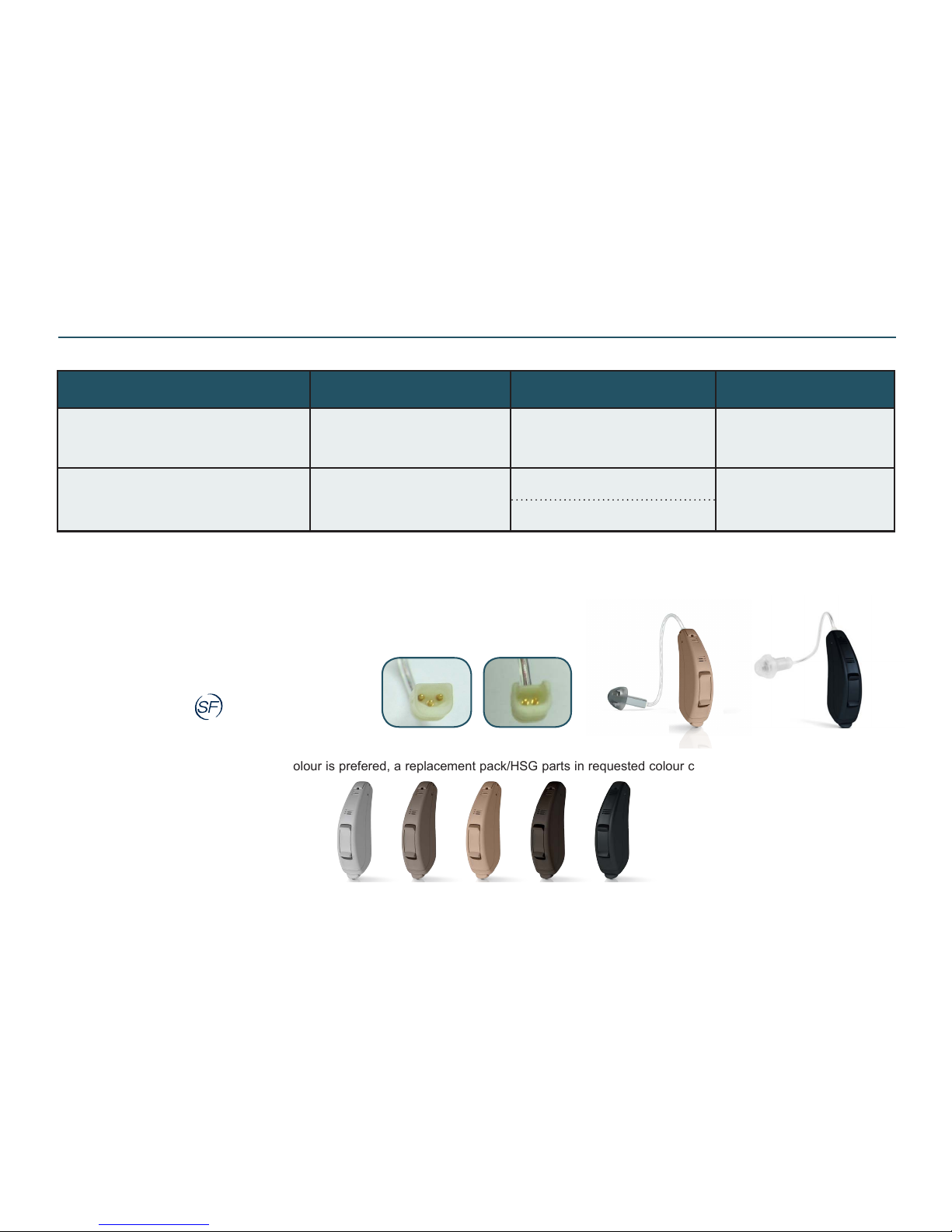
This Technical Manual serves to outline the service & postponement procedure for products listed in the form-factor-matrix above. Furthermore the
doc No for Product Information/Data sheet is listed for a more detailed product information
Product Information - STEP C4.5
Note:
HI is available in BGE colour. If another colour is prefered, a replacement pack/HSG parts in requested colour can be ordered. Replacement packs
are available in these colours:
Medium Blonde (MBL)
Dark Brown (DBR)
Black (BLK)
Sterling Grey (STG)
ST660
with 3 pin rec
ST460/260-DRW mounted w
2 pin rec (S,NP & HP recs)
ST660-DRW mounted
w 3 pin rec
ST460/260
with 2 pin rec
MBLSTG BGE DBR BLK
INT ST660-DRW, 3 PIN REC:
Can be tted with 4 different power levels:
Low Power (LP)
Medium Power (MP)
High Power (HP)
Ultra Power (UP)
Must be mounted with SureFit™ 3 pin rec
Page 4
Doc 0219660 rev. K
Page 4 of 32
Not subject to issue control when printed
C4.1 Product Model
Data Sheet
Doc No
MILANO RIE 60
batt size 312 zinc air
2 pin rec
CRISP
(wireless)
CI360-DVIRW
400127000
CI260-DVIRW
SHARE
(non wireless)
SR1360-DVIR 400281000
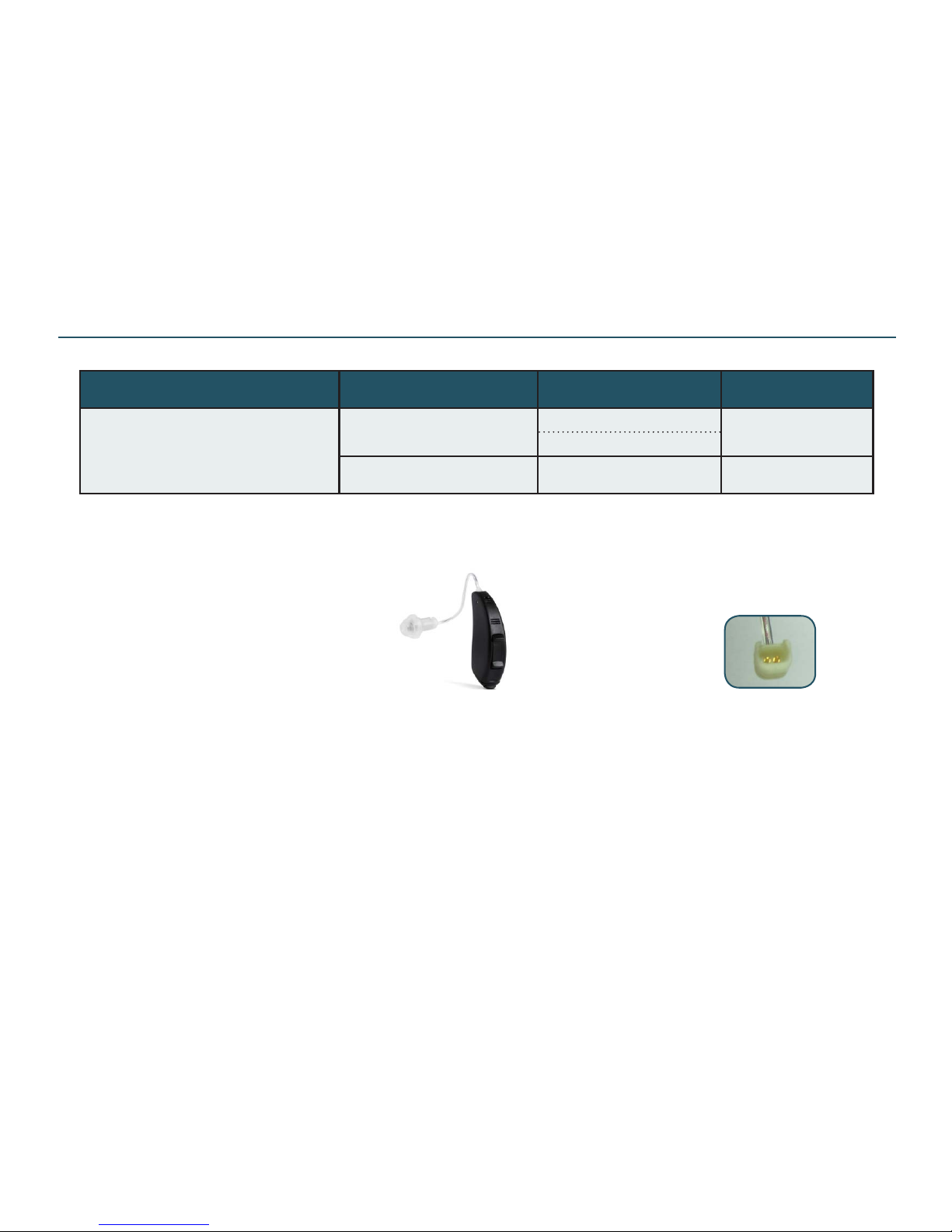
This Tech Manual serves to outline the service & postponement procedure for products listed in the form-factor-matrix above. Furthermore
the doc No for Product Information/Data sheet is listed for a more detailed product information
CRISP / SHARE 60
Product Information - CRISP & SHARE C4.1
HI is available in these colours:
Medium Blonde (MBL)
Dark Brown (DBR)
Beige (BGE)
Black/Marble Grey (BLK/MGR): BLK TGL,HSG BOT & BAT DR. MGR HSG TOP & CONN LOCK *
Black (BLK)
Sterling Grey (STG) - SHARE only: BLK TGL, HSG BOT, BAT DR & CONN LOCK. GRY3 HSG TOP
Crisp & Share are
mounted with 2 pin
rec tubes
*HI & parts in MGR have been terminated in May 2017 and will therefore no longer be available. Possible stock of spare parts can be used up
Page 5
Doc 0219660 rev. K
Page 5 of 32
Not subject to issue control when printed
Description Part No
PIN,0.6X5.0 (top/bot HSG, all models) 18035700
PIN,0.6X4.5 (batt door, CI & SR models) 17010500
PIN,0.6X6.6 (batt door, ST models) 15344300
PIN,0.50X4.40 (TGL, CI & SR models) 15156000
CAP,TOGGLE,COPLAND RIE (soft sil cap) 18858600
KIT,COLOUR MARKERS,INT,MRIE 18167200
CHILD LOCK, RED, P60 (colour mrk) 16165800
CHILD LOCK, BLUE, P60 (colour mrk) 16165801
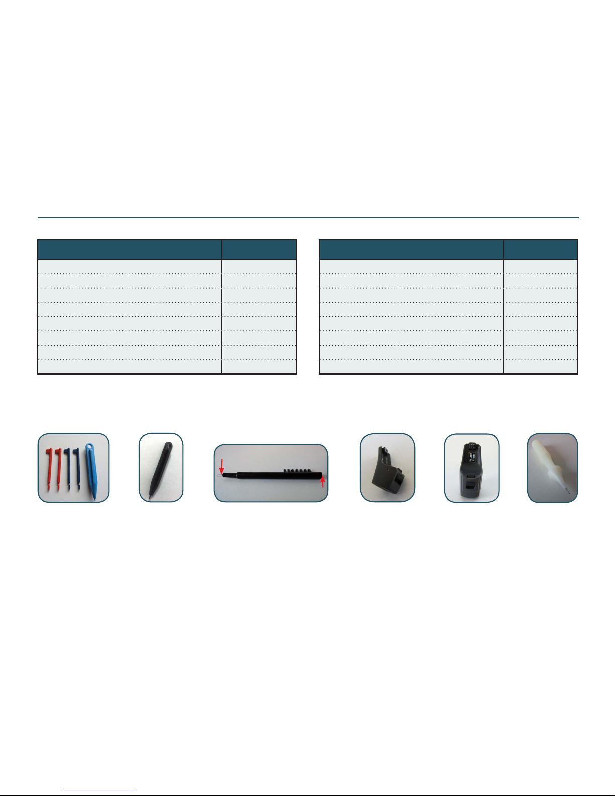
Brush, black Pin removal
tool
Magnet
Cleaning
loop
Colour
markers
Mandrel
Part List
Integrated
FM adaptor
Child lock tool
p/n 18106800
(mandrel)
Description Part No
INTEGRD FM ADAPT HA,INT,NANO (EU) 18642600
INTEGRD FM ADAPT NB,INT,NANO (US/CA) 18642601
CHILDLOCK RELEASE TOOL (mandrel) 18106800
MANDREL (blue plastic) 0490-059
PIN REMOVAL TOOL PACKED 15502500
GENERIC BRUSH, BLK 17435000
DAI ADAPT2 (audio shoe w/3pin euro socket)
19901700
AUTOPHONE MAGNETS (3 pcs) 17294600
DAI adapt 2
(f/ 3pin euro plug)
Page 6
Doc 0219660 rev. K
Page 6 of 32
Not subject to issue control when printed
Description Part No
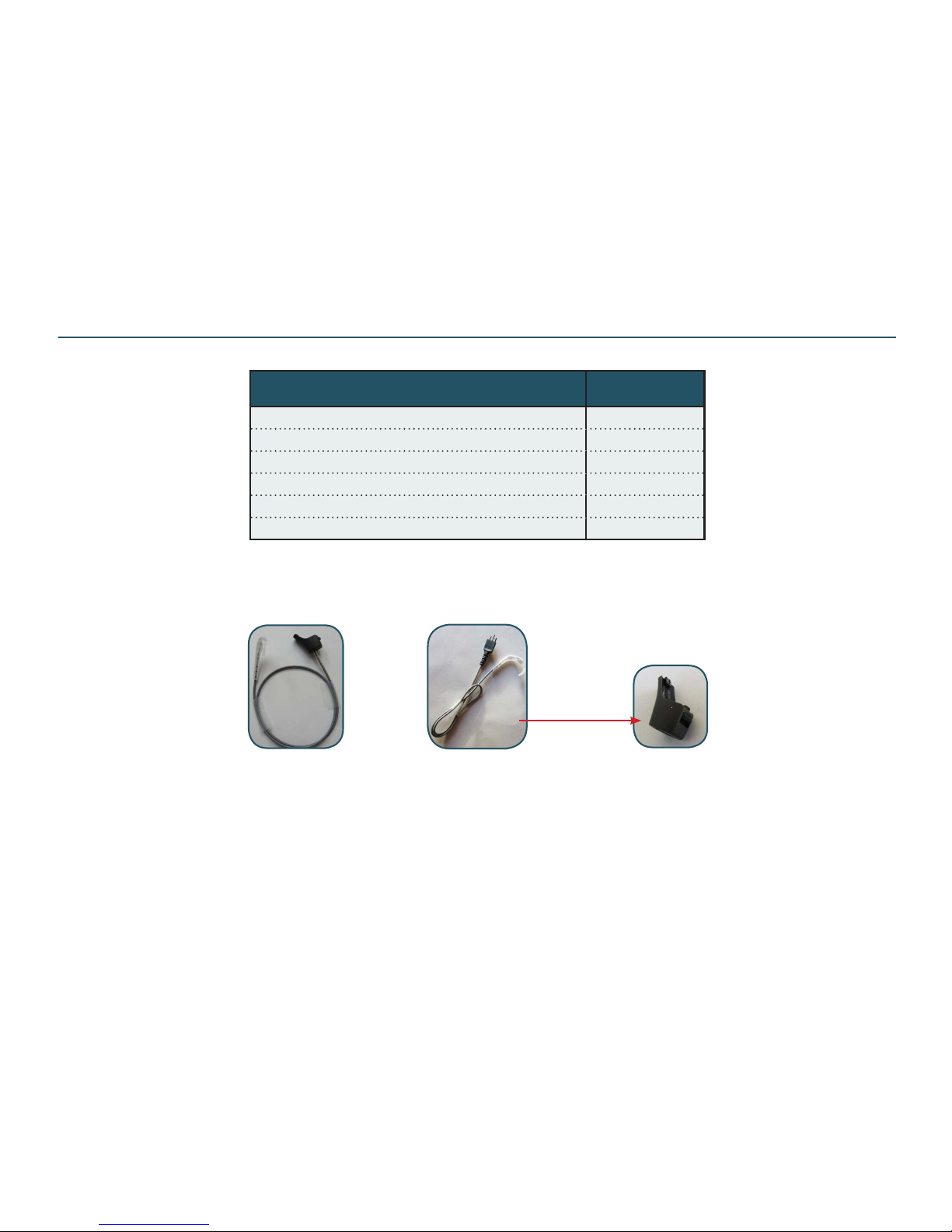
CROS,SUREFIT,AUDIO SHOE,SMALL * 20040900
CROS,SUREFIT,AUDIO SHOE,MEDIM * 20041000
CROS,SUREFIT,AUDIO SHOE,LARGE * 20041100
CROS,SUREFIT,EUROPLUG,SMALL * 20040500
CROS,SUREFIT,EUROPLUG,MEDIUM * 20040600
CROS,SUREFIT,EUROPLUG,LARGE * 20040700
CROS,SF
EURO PLUG
(to be connected to a
suitable AUD shoe)
CROS,SF
AUD SHOE
(shoe is xed to the cable)
* Lengths: S = 25 cm, M = 28 cm, L = 31 cm (excl CROS hook)
Part List - CROS SUREFIT
DAI adapt 2
(f/ 3pin euro plug)
Please also see: Doc 400604000 UG,CROS/BICROS,SUREFIT (User Guide) & 400650000 DS,CROS/BICROS,SUREFIT,GB (Data Sheet)
Page 7
Doc 0219660 rev. K
Page 7 of 32
Not subject to issue control when printed
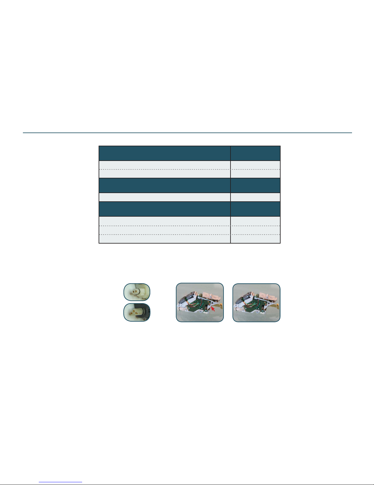
Service modules are not serviceable at local site. Instead defective ones must be
returned to Global Repair Site
Prog Service module/ASM frame
Prog Service Module/ASM FRAME (C4.1)
CRISP
Part No
CI360-DVIRW 18496700
CI260-DVIRW 18946200
Prog Service Module/ASM FRAME (C4.1)
SHARE
Part No
SR1360-DVIR 19159800
Prog Service Module/ASM FRAME (C4.5)
STEP
Part No
ST660-DRW (3 pin rec plug) 20051700
ST460-DRW 19154400
ST260-DRW 19154500
s/n
label
CRISP & SHARE
2 pin plug for rec
3 pin plug for rec
STEP models only: The s/n label is placed next
to the batt spring. Please note that replacing the
prog serv module means a new s/n
STEP
Part List - Prog Service Module/ASM FRAME
Page 8
Doc 0219660 rev. K
Page 8 of 32
Not subject to issue control when printed
Description Part No
PROG. CABLE EXTENSION, MILANO (must be
used during HI test due to current measurement)
17517800
PROG CABLE R (CS44) 9022 907 69019
PROG CABLE L (CS44) 9022 907 69029
PROG ADAPTOR (incl guide & prog adapt clips) 18041400
CLIP,PROG ADAPTOR,RED 17736900
CLIP,PROG ADAPTOR,BLUE 17736901
PROG ADAPTOR CABLE,L,500* 18331000
PROG ADAPTOR CABLE,R,500* 18331100
PROG ADAPTOR CABLE,L,2500* 18331200
PROG ADAPTOR CABLE,R,2500* 18331300
COUPL MIC,TSYS,TM-12,MEASURED 18220700
* Prog adapt w/FXD cable can be
used during tting
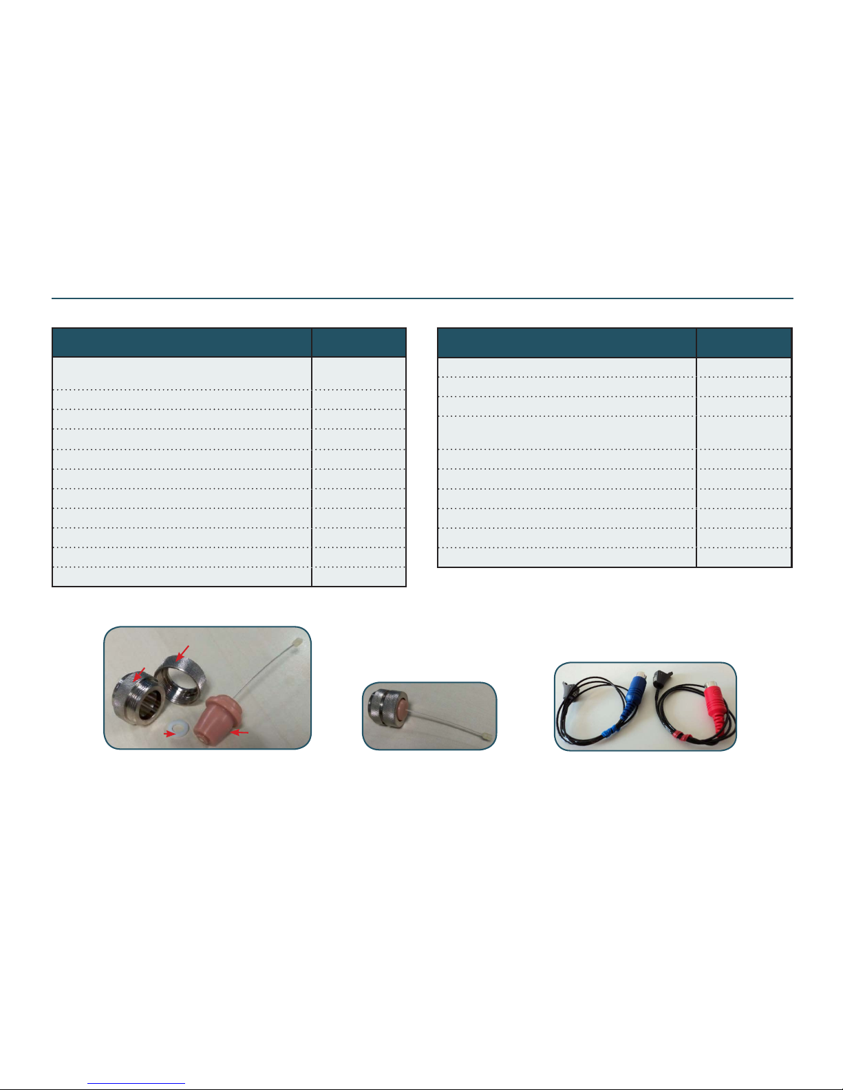
Part List - Test Equipment, 3 Pin
Please nd more pics and p/n’s of test equip. in the last pages
Description Part No
AIRLINK,COMPL (for wireless connection test)** 17292000
AIRLINK 2,GENERIC (for wl connection test)** 17292002
TEST JIG, BERLIN RIE (to x HI during nal test) 19429000
FRAME
(BLK test frame for ATC4000 sound chamber)
16902800
ASM TEST REC UP 3 PIN 20011700
DSA ADAPTOR 20011800
THREAD CAP 20011900
RUBBER WASHER 20012000
CONE RECEIVER 20012100
BATTERY PILL 312 17449300
ASM TEST REC UP 3 PIN
p/n 20011700
Disassembled ASM TEST REC UP 3 PIN
to show the individual parts
THREAD CAP
p/n 20011900
DSA ADAPT
p/n 20011800
RUB WASH
p/n 20012000
CONE REC
p/n 20012100
** both can be used
Page 9
Doc 0219660 rev. K
Page 9 of 32
Not subject to issue control when printed
Description Part No
PROG. CABLE EXTENSION, MILANO
(must be used during nal HI test due to current measurement)
17517800
PROG CABLE R (CS44) 9022 907 69019
PROG CABLE L (CS44) 9022 907 69029
PROGRAMMING ADAPT (incl prog adapt clip red & blue) 18041400
CLIP,PROGRAMMING ADAPTOR,RED 17736900
CLIP,PROGRAMMING ADAPTOR,BLUE 17736901
PROG ADAPTOR CABLE,L,500* 18331000
PROG ADAPTOR CABLE,R,500* 18331100
PROG ADAPTOR CABLE,L,2500* 18331200
PROG ADAPTOR CABLE,R,2500* 18331300
COUPL MIC,TSYS,TM-12,MEASURED 18220700
TEST FIXTURE (for HI during nal test - test rec incl) 17850700
TUBE,REC,REWORKED (for nal HI test) 17460000
COUPLER INSERT,DSA (brass) 16169300
FRAME (test frame for ATC4000 test chamber) 16902800
AIRLINK,COMPL PKG (wireless connection test) 17292000
BATTERY PILL 312+ 17449300
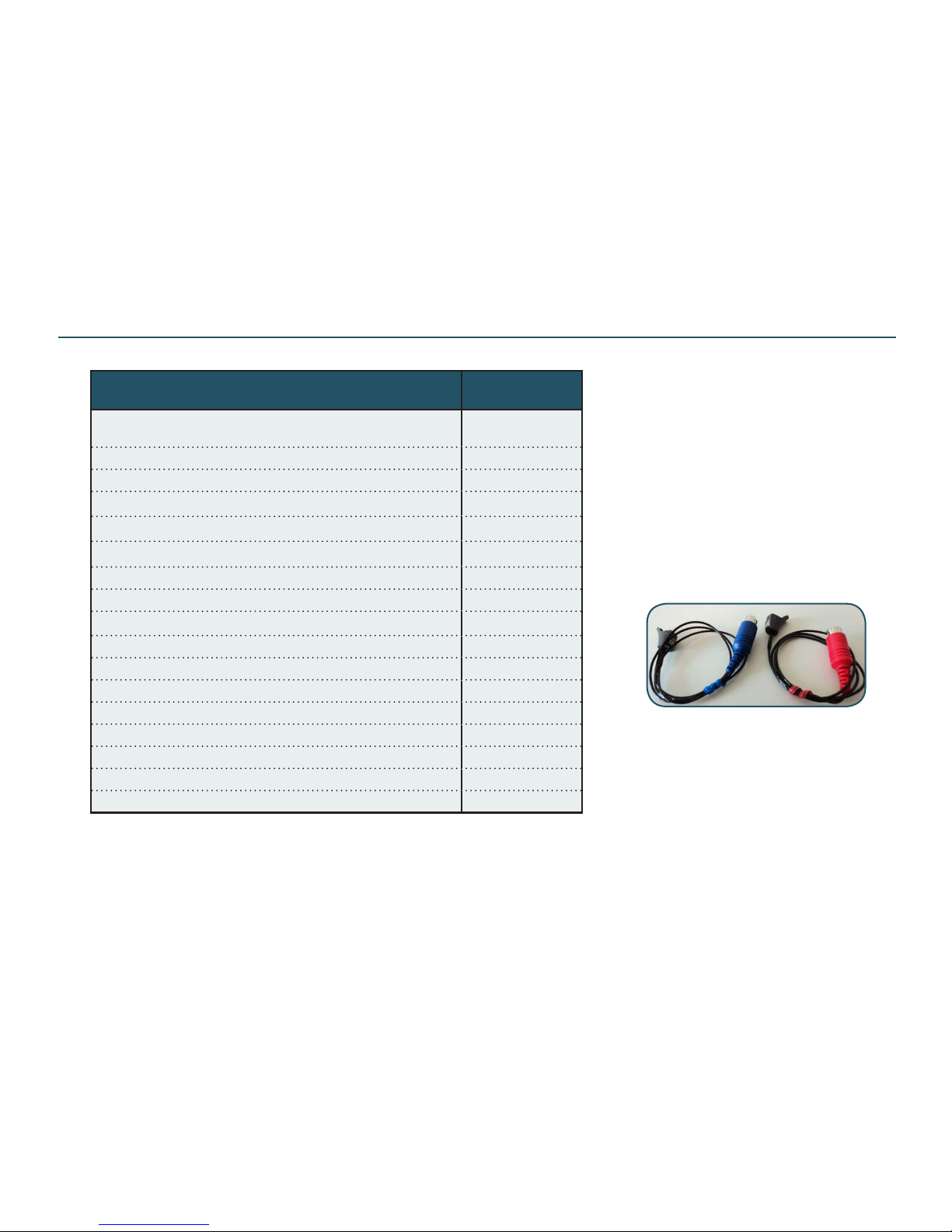
* Prog adaptors with xed cable (for tting purpose only)
Please nd pictures of test equipment on the last pages
Part List - Test Equipment, 2 Pin
Prog adapt w/FXD cable can be used
during tting using tting SW
Page 10
Doc 0219660 rev. K
Page 10 of 32
Not subject to issue control when printed
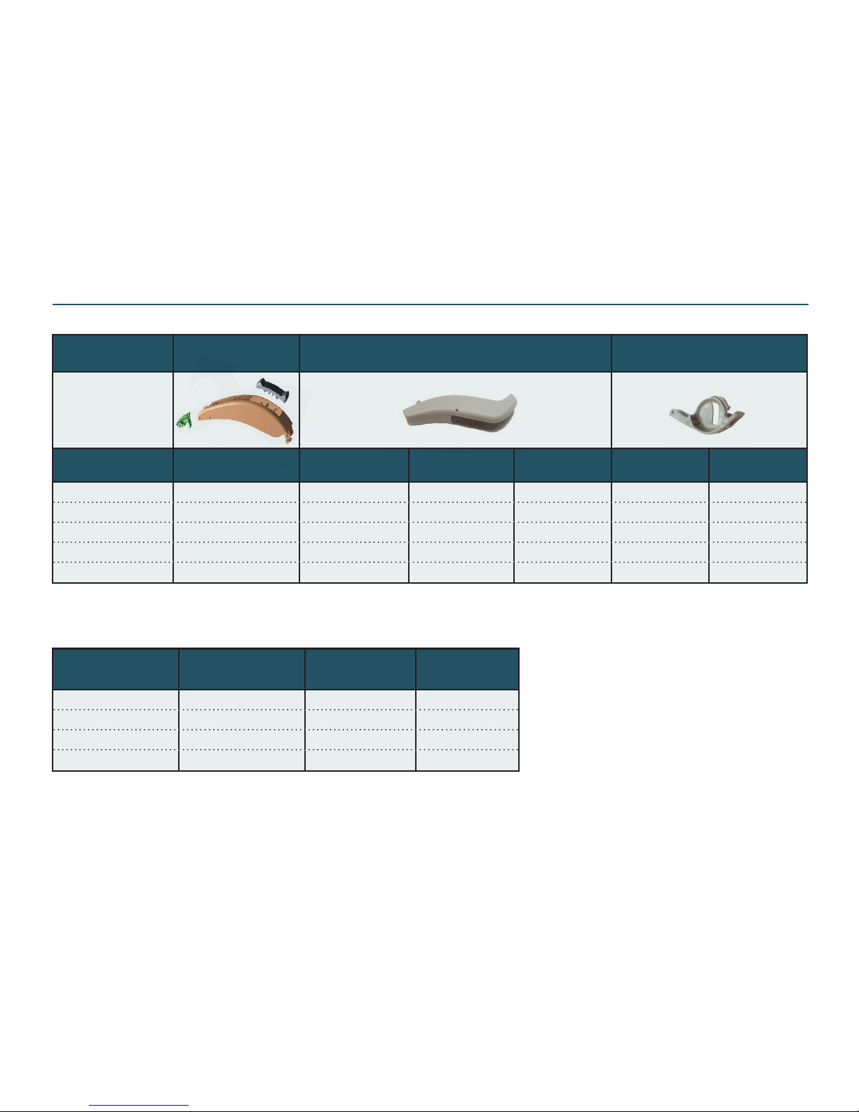
Part List - HSG Parts & Repl Packs - STEP Models
* TOP HSG ASM w/TGL & conn
* lock (shown in diff colours for
*ieasy identication)
COLOUR
HSG,TGL,LOCK
ASM *
BOT HSG,PTD ** BATT DOOR
ST660-DRW ST460-DRW ST260-DRW ST660-DRW
ST460/260-
DRW
MBL 18729102 20037002 19096702 19151002 20036902 19096302
DBR 18729104 20037004 19096704 19151004 20036904 19096304
BGE 18729105 20037005 19096705 19151005 20036905 19096305
BLK 18729108 20037008 19096708 19151008 20036908 19096308
STG 18729120 20037020 19096720 19151020 20036920 19096320
Note: All HSG parts are nano coated
REPLACEMENT
PACK - COLOUR
ST660-DRW ST460-DRW ST260-DRW
MBL 20036802 19095702 19150902
DBR 20036804 19095704 19150904
BLK 20036808 19095708 19150908
STG 20036820 19095720 19150920
** BOT HSG with model name
Page 11
Doc 0219660 rev. K
Page 11 of 32
Not subject to issue control when printed
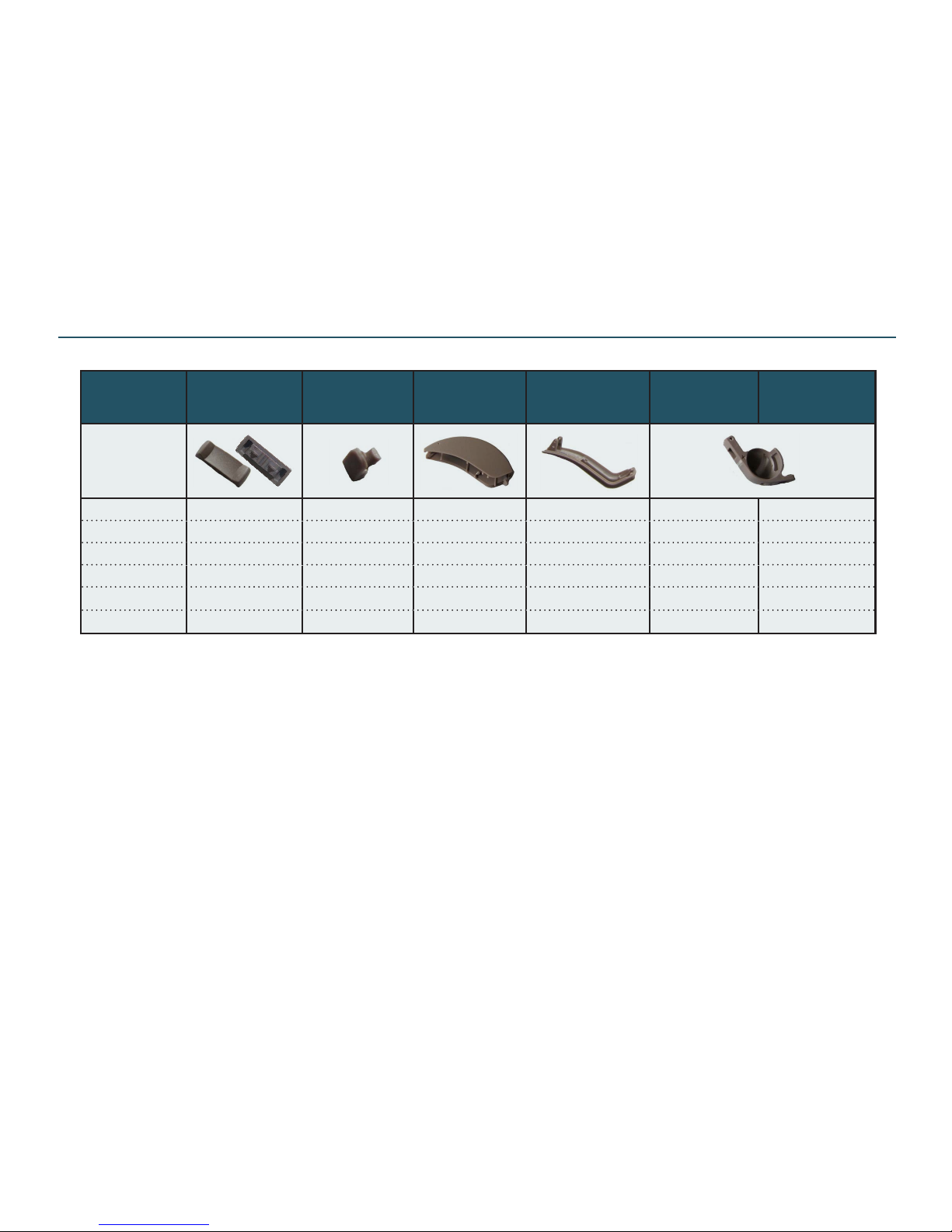
Colour
TGL
(w/o a pin
mounted) *
CONN LOCK
TOP HSG
PTD
BOT HSG
BATT DOOR
SHARE
BATT DOOR
CRISP
MBL 18176102 18176302 18516502 18176402 19159902 18516602
DBR 18176104 18176304 18516504 18176404 19159904 18516604
BGE 18176105 18176305 18516505 18176405 19159905 18516605
MGR N/A 18176307 18516507 N/A N/A N/A
BLK 18176108 18176311 18516508 18176411 19159908 18516608
GRY3 N/A N/A 18516520 N/A N/A N/A
Note: All HSG parts are nano coated. Please see “Product Information” page concerning HSG part colours
* The TGL is delivered with a hole for a pin (pin p/n 15156000). Please see the page “Replacing Parts” describing how to mount the pin
Part List - HSG Parts - SHARE & CRISP Models
Note: HI & spare parts in MGR colour have been terminated in May 2017 and will therefore no longer be available. Possible stock of spare
parts can be used up
Page 12
Doc 0219660 rev. K
Page 12 of 32
Not subject to issue control when printed
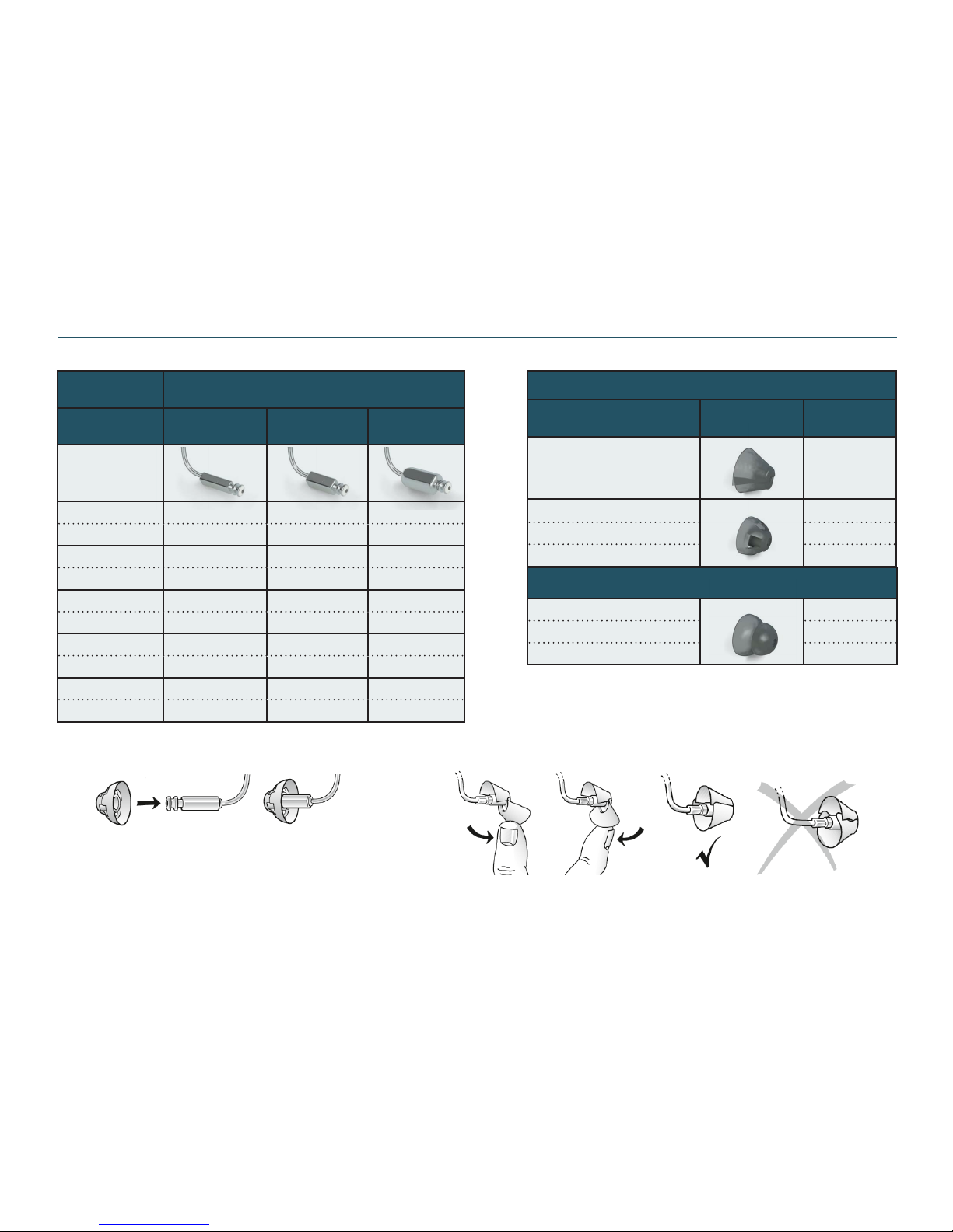
Part List - SureFit (SF) / SureFit2 (SF2) Rec Tubes (3 pin)
SUREFIT 2 (SF2)
(1 pc/each blister pack)
Size LP MP HP
0L 20105100 20104100 20103100
0R 20105200 20104200 20103200
1L 20105300 20104300 20103300
1R 20105400 20104400 20103400
2L 20105500 20104500 20103500
2R 20105600 20104600 20103600
3L 20105700 20104700 20103700
3R 20105800 20104800 20103800
4L 20105900 20104900 20103900
4R 20106000 20105000 20104000
SUREFIT (SF) DOMES USED WITH LP / MP REC
Description
Bag
(10 pcs)
DOME,SF,TULIP,STD 19398500
DOME,SF,OPEN,SM 19398200
DOME,SF,OPEN,MDM 19398300
DOME,SF,OPEN,LGE 19398400
SUREFIT (SF) DOMES USED WITH HP REC
DOME,SF,PWR,SM 19398600
DOME,SF,PWR,MDM 19398700
DOME,SF,PWR,LGE 19398800
Mount the dome to the rec tube as shown: Make sure the tulip dome is mounted to the rec tube as shown:
Page 13
Doc 0219660 rev. K
Page 13 of 32
Not subject to issue control when printed
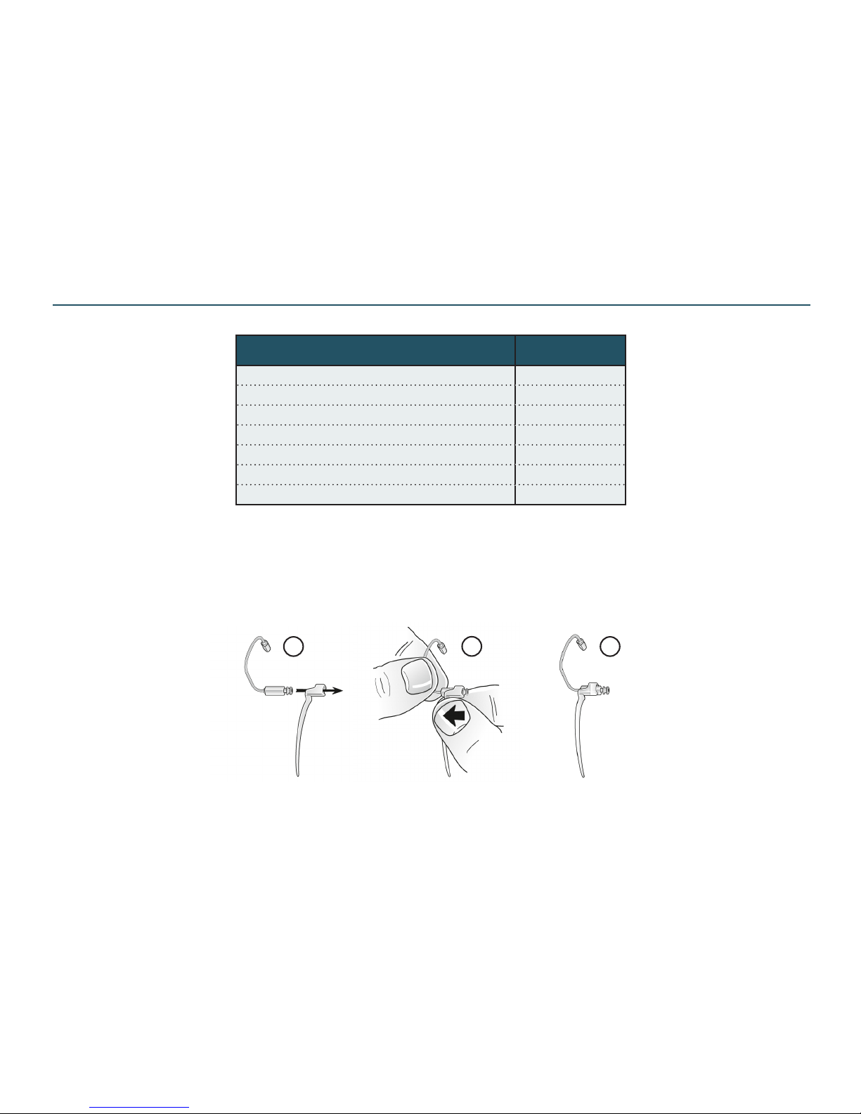
Part List - SureFit 2 Access (for rec tubes w 3 pin conn)
* contains all sizes rec tubes, domes, sportlocks, measurement, tool & lters
**empty box with inlay - to be lled up according to needs
Choose the suitable LP/MP/HP sport lock. Mount rec tube to the sport lock:
Description Part No
FITTING KIT,REC,SUREFIT 2* 20156300
FITTING KIT,REC,SF2(EMPTY)** 20260600
WAX PROTECTOR,CERUSTOP,BOX,8PC 549-010-000-00
MEASUREMENT TOOL,MINI BTE 15200800
SPORT LOCK,SF LP,BAG,10 19428000
SPORT LOCK,SF MP,BAG,10 19428200
SPORT LOCK,SF HP,BAG,10 19428300
3
2
1
Page 14
Doc 0219660 rev. K
Page 14 of 32
Not subject to issue control when printed
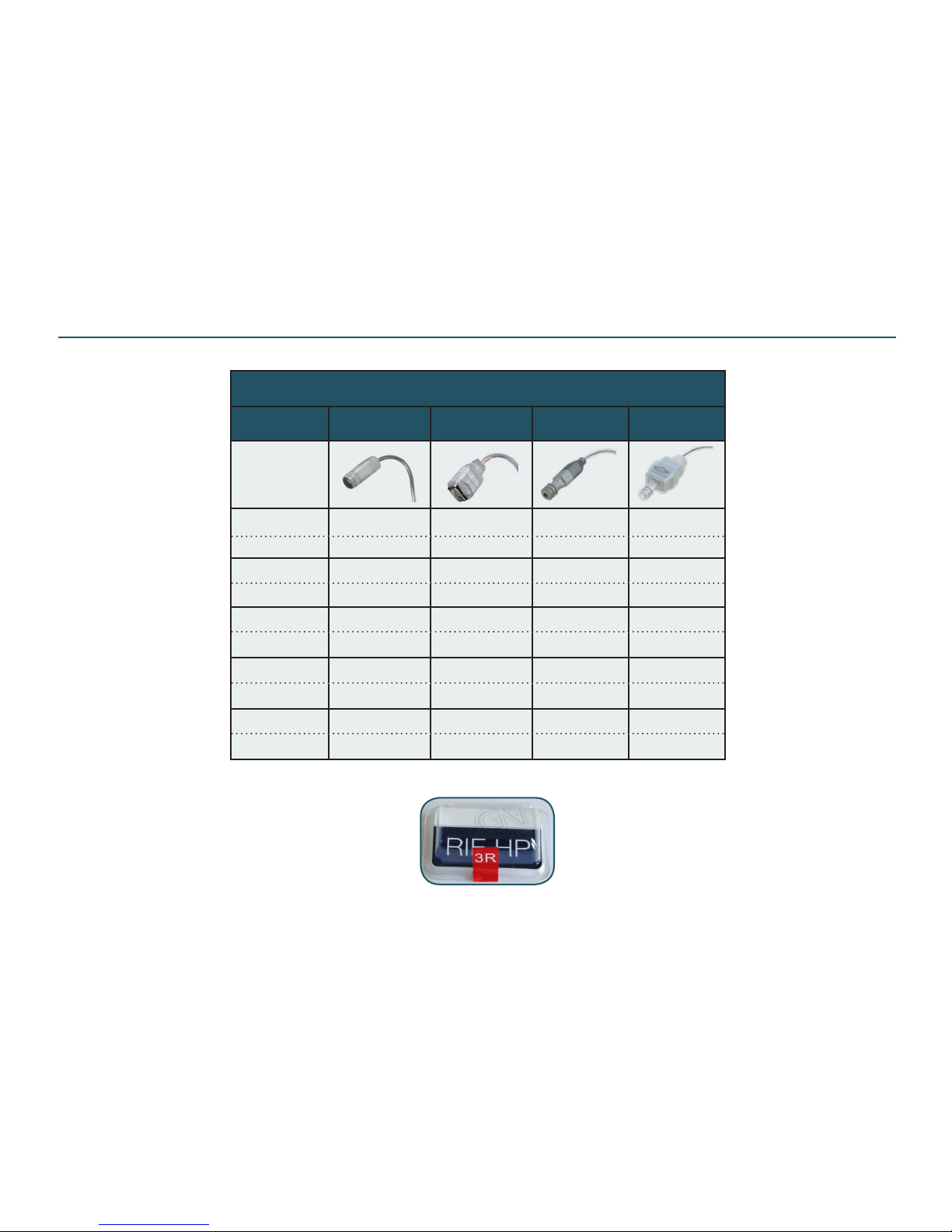
** New smaller rec w/ thin tube tip. Performance close to current NP (off 2-3 dB in the high freq)
** New HP rec w/ thin tube tip. Performance may be off 1-2 dB at high freq on C4.1 based models
Rec tube blister pack
containing one rec
mounted into a tube
Rec Tube Blister Pack
Size NP HP S (small) * HP2 **
0L
18581300 18582300 18520300 18521500
0R 18581400 18582400 18520400 18521600
1L
18581500 18582500 18520500 18521700
1R
18581600 18582600 18520600 18521800
2L
18581700 18582700 18520700 18521900
2R
18581800 18582800 18520800 18522000
3L
18581900 18582900 18520900 18522100
3R
18582000 18583000 18521000 18522200
4L
18582100 18583100 18521100 18522300
4R
18582200 18583200 18521200 18522400
Part List - Rec Tubes & Domes (rec tubes with 2 pin connector)
Page 15
Doc 0219660 rev. K
Page 15 of 32
Not subject to issue control when printed
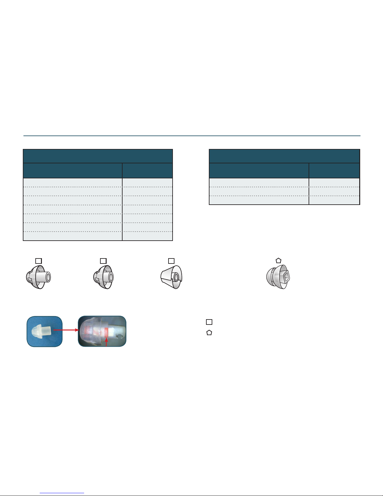
DOMES USED WITH NP REC
Description
Bag
(10 pcs)
DOME,REC,SZ5,SM 18501200
DOME,REC,SZ7,MDM 18501300
DOME,REC,SZ10,LGE
18501400
DOME,REC,EXT,SZ5,SM * 18501500
DOME,REC,EXT,SZ7,MDM * 18501600
DOME,REC,EXT,SZ10,LG * 18501700
DOME,REC,TULIP,STD
18501800
Dome EXT
Power Domes
Sizes S,M,L
Dome
STD Tulip
Domes
Sizes S,M,L
* EXT: Extended length (longer tube)
Slide the dome down over the rec until the red (R)
/ blue (L) mark on rec is completely covered
Part List - Domes for NP & HP Receiver (for rec tubes with 2 pin connector)
DOMES USED WITH HP REC
Description
Bag
(10 pcs)
DOME,REC,PWR,SM 18501900
DOME,REC,PWR,MDM 18502000
DOME,REC,PWR,LGE 18502100
Dome EXT
Sizes S,M,L
Normal Power dome compatible
High Power dome compatible
R
H
R R
R
H
Page 16
Doc 0219660 rev. K
Page 16 of 32
Not subject to issue control when printed
DOMES USED WITH S REC
Description
Bag
(10 pcs)
DOME,THNTUB/REC,SZ5,SM 18500800
DOME,THNTUB/REC,SZ7,MDM 18500900
DOME,THNTUB/REC,SZ10,LGE
18501000
DOME,THNTB/REC,TULIP,STD 18501100
DOME,THNTUB/REC,PWR,SM 18265100
DOME,THNTUB/REC,PWR,MDM 18265200
DOME,THNTUB/REC,PWR,LGE 18265300
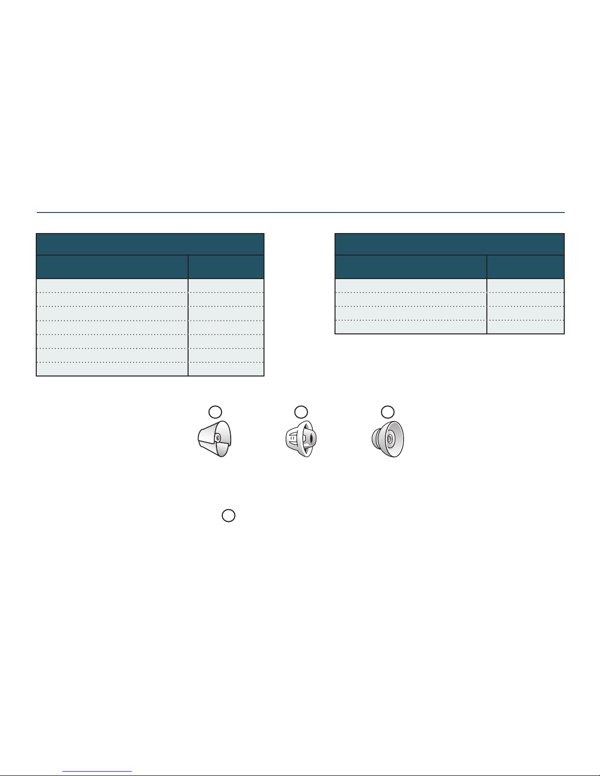
Power Domes
Sizes S,M,L
Dome
STD Tulip
Domes
Sizes S,M,L
DOMES USED WITH HP2 REC
Description
Bag
(10 pcs)
DOME,THNTB/REC,TULIP,STD 18501100
DOME,THNTUB/REC,PWR,SM 18265100
DOME,THNTUB/REC,PWR,MDM 18265200
DOME,THNTUB/REC,PWR,LGE 18265300
Part List - Thin Tube Domes for S & HP2 Rec (for rec tubes with 2 pin conn)
T T T
Receiver & thin tube dome compatible
T
Page 17
Doc 0219660 rev. K
Page 17 of 32
Not subject to issue control when printed
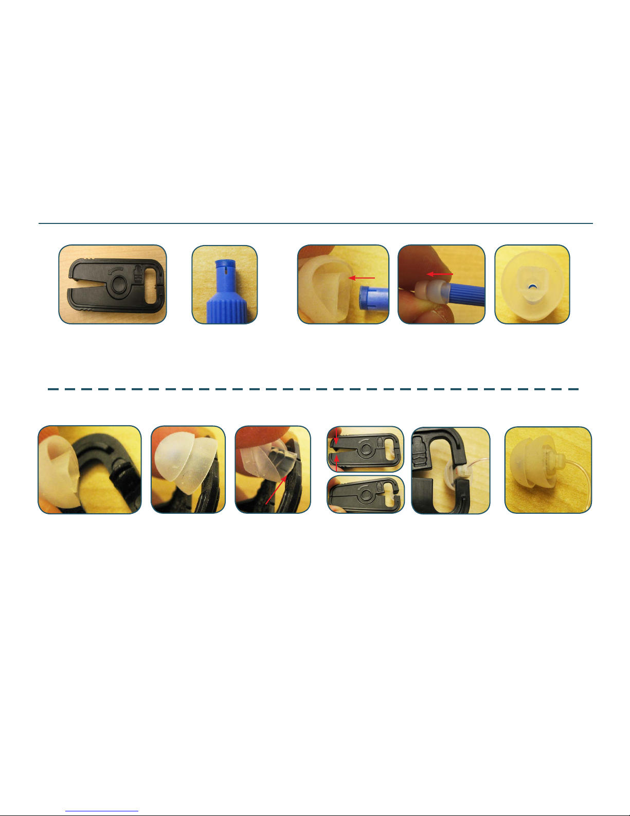
Power Dome Tool
p/n 15989900
As the HP rec is pushed
into the power dome,
carefull pull out the
power dome tool
Place the longer length of the rectangular cavity of the power dome over
the power dome tool
Ensure that the power dome is installed on the power dome tool by checking
it and it is ushed even with the tool as shown (3rd pic)
Squeeze and hold bottom of the power
dome tool to open the power dome rectangular cavity.
Insert the HP rec, with the longer length of
the rec parallel to the longer length of the
rectangular cavity of the power dome
Prepare a HF3
tool with HF3
Insert HF3 tool with HF3 all the way in the power dome until it passes
through the rectangular cavity of the power dome
Power Dome Tool (HP 2 pin rec)
Page 18
Doc 0219660 rev. K
Page 18 of 32
Not subject to issue control when printed
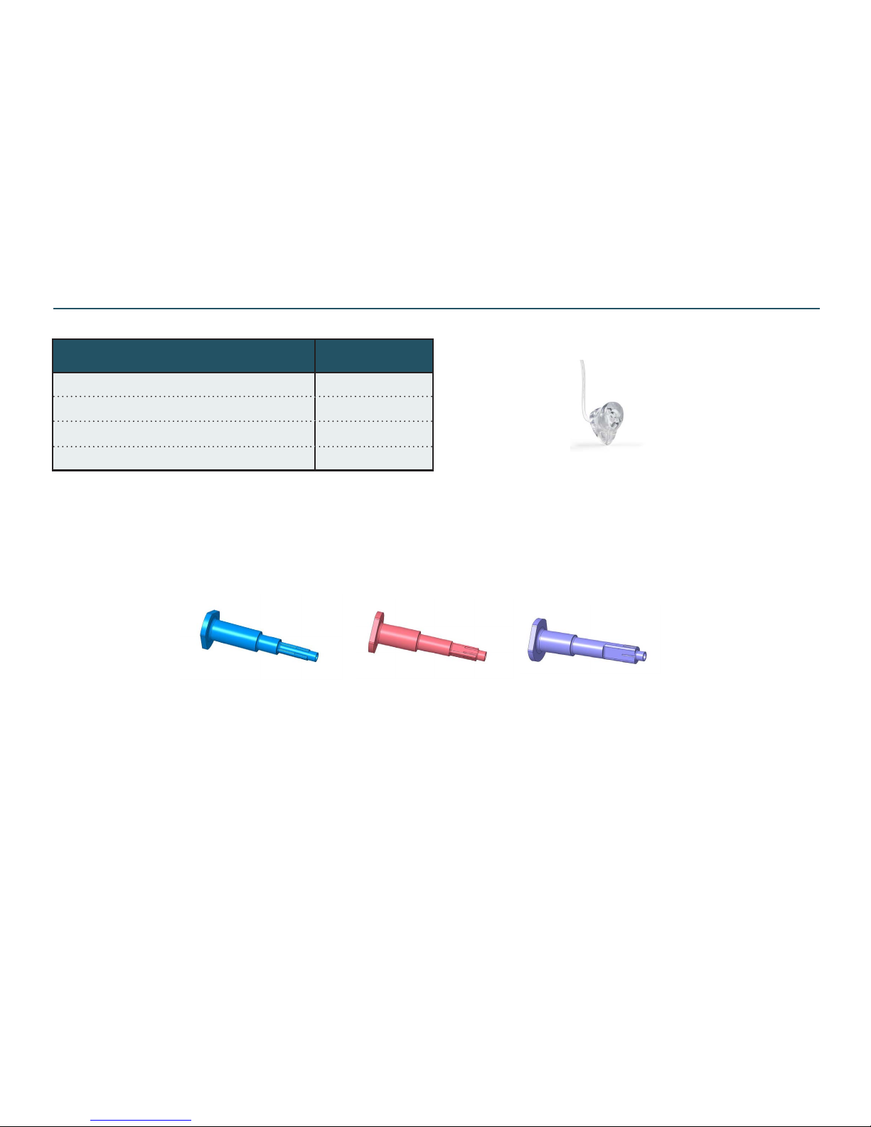
Part List - Accessories - Custom Insert Option for 3 pin rec
Description Part No
MANDREL,LP REC,NANO 20016400
MANDREL,MP REC,NANO 20016500
MANDREL,HP REC,NANO 20016600
SIL RUBBER,.085 IN,VENT,WHT 12192-006
MANDREL,LP REC MANDREL,MP REC MANDREL,HP REC
Custom insert option
Note:
For custom insert option instead of std rec domes, follow the instr in doc 0280210 RIE CUST INS & HOLLOW CAV,3PIN posted on the GTO website
Page 19
Doc 0219660 rev. K
Page 19 of 32
Not subject to issue control when printed
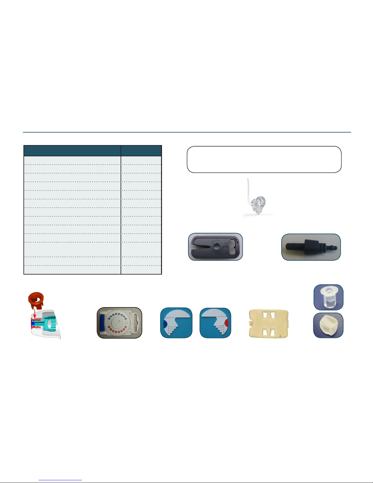
Part List - Accessories (incl Custom Insert Option for 2 pin rec)
Custom insert option
Description Part No
RECEIVER TUBE REBENDING KIT 16964200
SPORTLOCKS, BAG 10 PCS * 539-052-000-00
SPORT LOCK,S-REC,BAG,10 ** 18964000
FLTR,DISP,RED/BLU,HF3 18595900
ADAPTER,HP EARMOLD,RED 18252900
ADAPTER,HP EARMOLD,BLUE 18252910
CUSTOM INSERT TIP, NP 15988700
INSERT, RIE HP CUSTOM TIP 15989000
HP RECEIVER CUSTOM INSERT TOOL 15989100
GASKET, RIE HP CUSTOM TIP 15990000
WAX REMOVER (can be used as rec
removal tool for custom tip earmould)
1186801
POWER DOME TOOL KIT (tool & guide) 15990600
MEASUREMENT TOOL 15200800
** Sportlocks for HP/NP/HP2 recs ** Sportlocks for S recs
Note:
For custom insert option instead of standard domes, follow Custom
iInsert Process Doc 0160240 posted on GTO website
Power dome tool
(HP recs - see page “Power Dome Tool”)
Tool HP rec custom insert
Meassurement Tool
One side for L & the other side for R
Custom insert tips
NP
HF3 Filter
(8 x red & 8 x blue)
Gasket RIE HP
(placed into custom insert tips)
Earmould adapt for HP2 & S recs
- rec tubes with thin tube tip
HP
HP earmould adapt
glued into custom earmould
Page 20
Doc 0219660 rev. K
Page 20 of 32
Not subject to issue control when printed
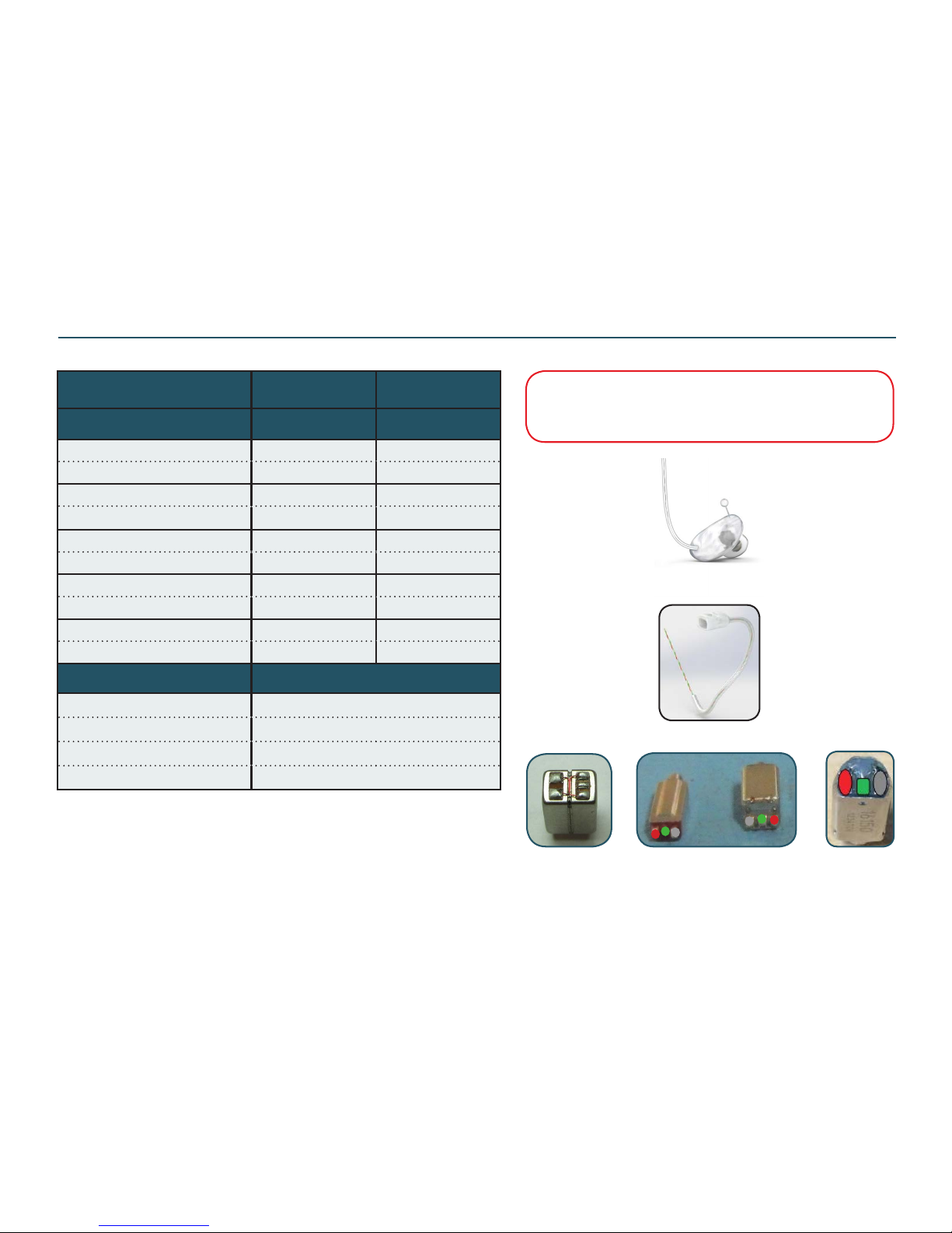
Part List - Optional N-Cased Earmould, 3 Pin
Note:
If the UP rec is to be mounted, the N-Cased earmould must
be chosen. Please follow “N-Cased Earmould Process,RIE”
Doc 0248970 (for all sizes recs) - posted on GTO website
TUBE 3 PIN2
ENCASED EM RIE
TUBE 3 PIN3
ENCASED EM RIE
SIZE Part No Part No
SZ 0L
20097700 20588700
SZ 0R
20097710 20588710
SZ 1L
20097720 20588720
SZ 1R
20097730 20588730
SZ 2L
20097740 20588740
SZ 2R
20097750 20588750
SZ 3L
20097760 20588760
SZ 3R
20097770 20588770
SZ 4L
20097780 20588780
SZ 4R
20097790 20588790
Receiver Part No
REC,SONION 37AP015K (UP) 19413100
REC,ENCAS EM (HP) 20085800
REC,26UA01X (MP) 19701700
REC,E25SA010X/D (LP) 19701800
Difference between TUBE 3 PIN2 & TUBE 3 PIN3 is the length of the rec
cable after nal bend. TUBE 3 PIN3 has 3 mm longer rec cable after the nal
bend (can help to avoid making the N-cased shells bigger to reach the tube)
TUBE,ENCASED EM,RIE
REC,UP REC,LP REC,MP REC,HP
Page 21
Doc 0219660 rev. K
Page 21 of 32
Not subject to issue control when printed
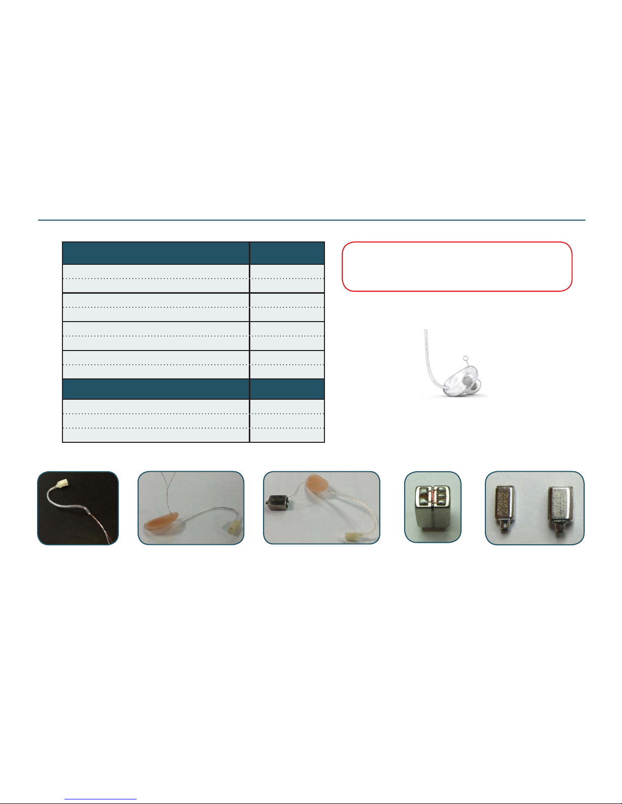
Part List - Optional N-Cased Earmould, 2 Pin
Description Part No
TUBE,ENCASED EARMOLD,RIE,SZ 1L 18956520
TUBE,ENCASED EARMOLD,RIE,SZ 1R 18956530
TUBE,ENCASED EARMOLD,RIE,SZ 2L 18956540
TUBE,ENCASED EARMOLD,RIE,SZ 2R 18956550
TUBE,ENCASED EARMOLD,RIE,SZ 3L 18956560
TUBE,ENCASED EARMOLD,RIE,SZ 3R 18956570
TUBE,ENCASED EARMOLD,RIE,SZ 4L 18956580
TUBE,ENCASED EARMOLD,RIE,SZ 4R 18956590
Description Part No
REC,SONION 37AP015K (UP rec) 19413100
REC,ED-7305/23X95 (HP) 15197900
REC,FH-6719-000 (LP) 15198000
Note:
If the UP rec is to be mounted, the N-Cased earmould is to
be chosen. Please follow “N-Cased Earmould Process,RIE”
Doc 0248970 posted in GTO website
P/n 189565*0 TUBE
ENCASED EM
tube w/ rec wires
for connecting the rec
The rec wires are passed through a hole in a cut faceplate and
the rec is connected. For detailed instr. please see doc 0248970
“N-Cased Earmould Process,RIE”
UP LP HP
Page 22
Doc 0219660 rev. K
Page 22 of 32
Not subject to issue control when printed
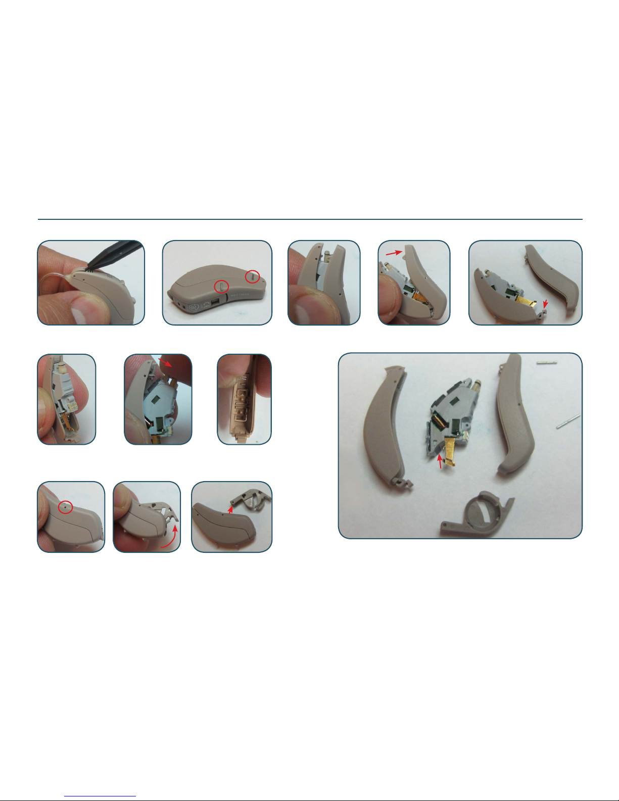
Disassemble Procedure & Replace Parts - STEP
Loosen the conn lock using the plastic mandrel and pull out the rec.
Locate the two pins and push them out using the pin removal tool
Separate the bot HSG from top HSG by sliding it off as shown. Be careful not to
damage the “tap” on the top HSG
Tap
Push out the service module as shown. Be aware that the top HSG
is assembled with conn lock and TGL. If an e.g. TGL is damaged,
the assembled top HSG must be replaced
If the batt door is damaged, it can be replaced without separating the
complete HI. Locate the one pin xing the batt door and push it out.
The batt door can now be pulled out and replaced to a new one
Top HSG ASM
w conn lock
& TGL
s/n label
Bot HSG
Batt door
Pin for
batt door
Pin for
top/bot HSG
Serv module
with s/n label
The STEP models do not have an ID plate like CRISP and SHARE.
Instead a s/n label is located next to the batt contacts. Replacing
a service module means a new s/n
Page 23
Doc 0219660 rev. K
Page 23 of 32
Not subject to issue control when printed
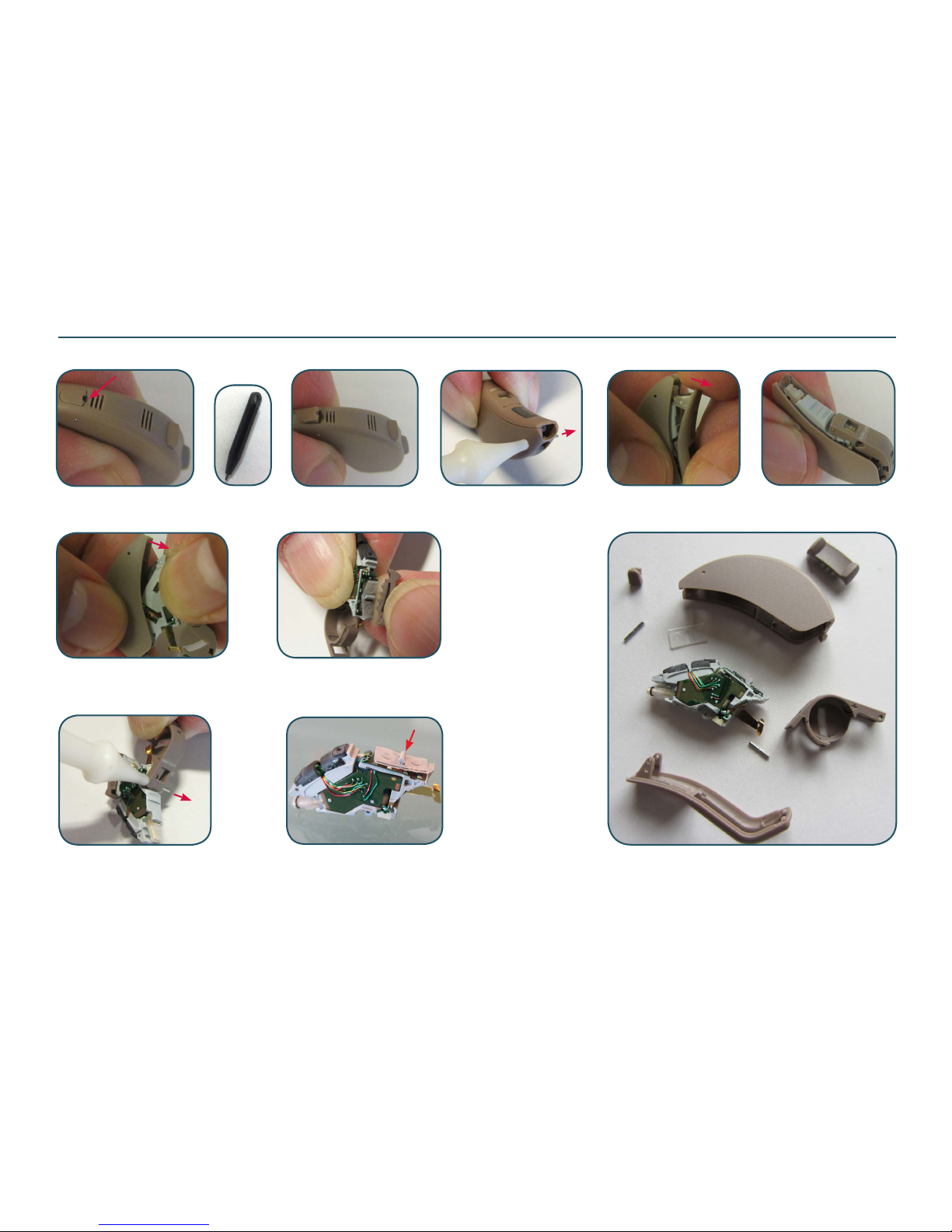
Disassemble Procedure - CRISP & SHARE
Unlock the rec by lifting up the conn lock using the mandrel. Push out the pin with a pin removal
tool and pull it out using a tweezer. The conn lock will then fall out without being damaged
Open batt door and pull out
the module
Gently separate the BOT HSG from TOP HSG
Push out the batt door pin
Service module/ASM frame
The soft silicone cap for toggle
must be correct in place before
assembling new HSG parts
Remove TGL by sliding it
Page 24
Doc 0219660 rev. K
Page 24 of 32
Not subject to issue control when printed
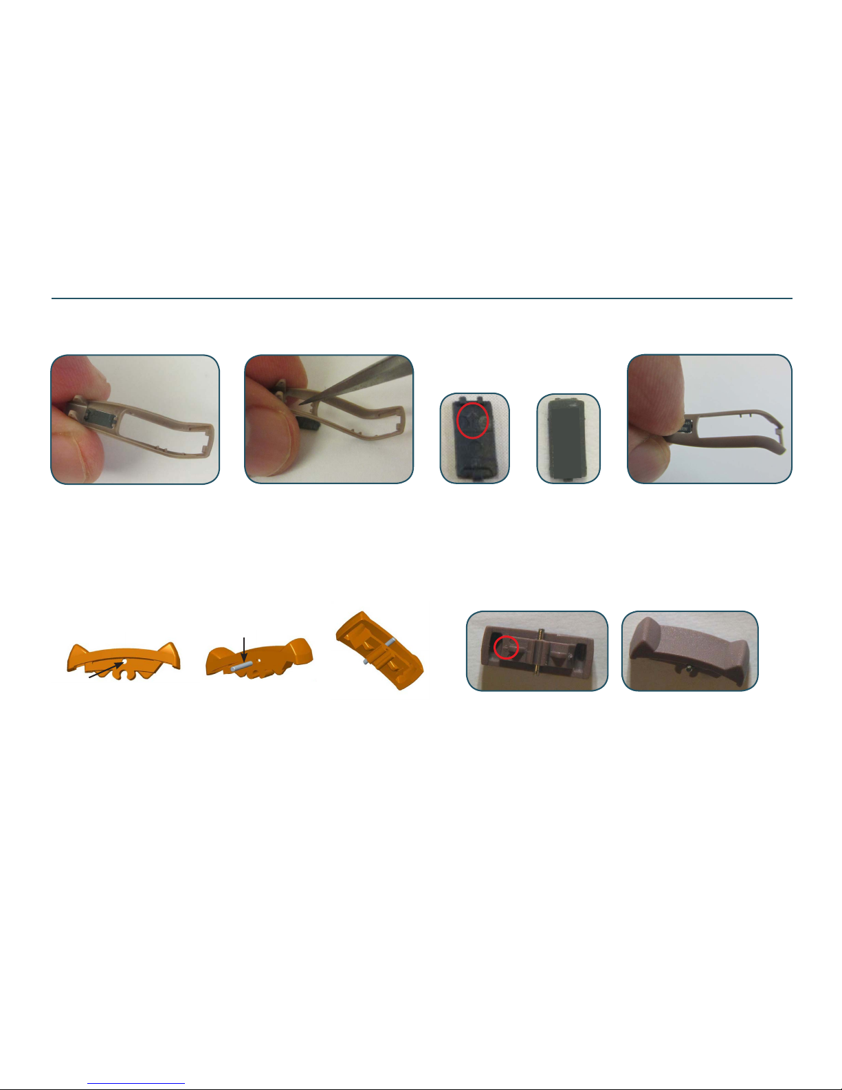
When replacing the bot HSG on Crisp & Share models, the ID plate must be transfered to new HSG. Please note that the ID plate is not an available
spare part. Push out the ID plate from inside. Place the side of the ID plate with one prong and insert it into new HSG. Use a nger to press down to
make sure both sides are correct in place
ID plate shown from both sides.
Turn the arrow/2 prong towards
the rec end
Replacing Parts - CRISP & SHARE
12 xxxxxxxx
CI360-DVIRW
TGL with pin mounted shown from both sides. Turn the arrow
towards the rec end when mounting. Always mount the TGL
before mounting the HSG parts
If the TGL is replaced a pin must be mounted to keep the TGL in place inside
the top HSG. The new TGL can only be attached to the ASM FRAME/module
after disassembling the HSG parts. Locate the hole for pin in the TGL and push
in the pin as shown. The pin must be placed exactly in the middle of the TGL
in order to be able to x the TGL correctly in the TOP HSG
Replacing BOT HSG:
Replacing TGL:
Pin p/n 15156000
Pin correct in place
Page 25
Doc 0219660 rev. K
Page 25 of 32
Not subject to issue control when printed
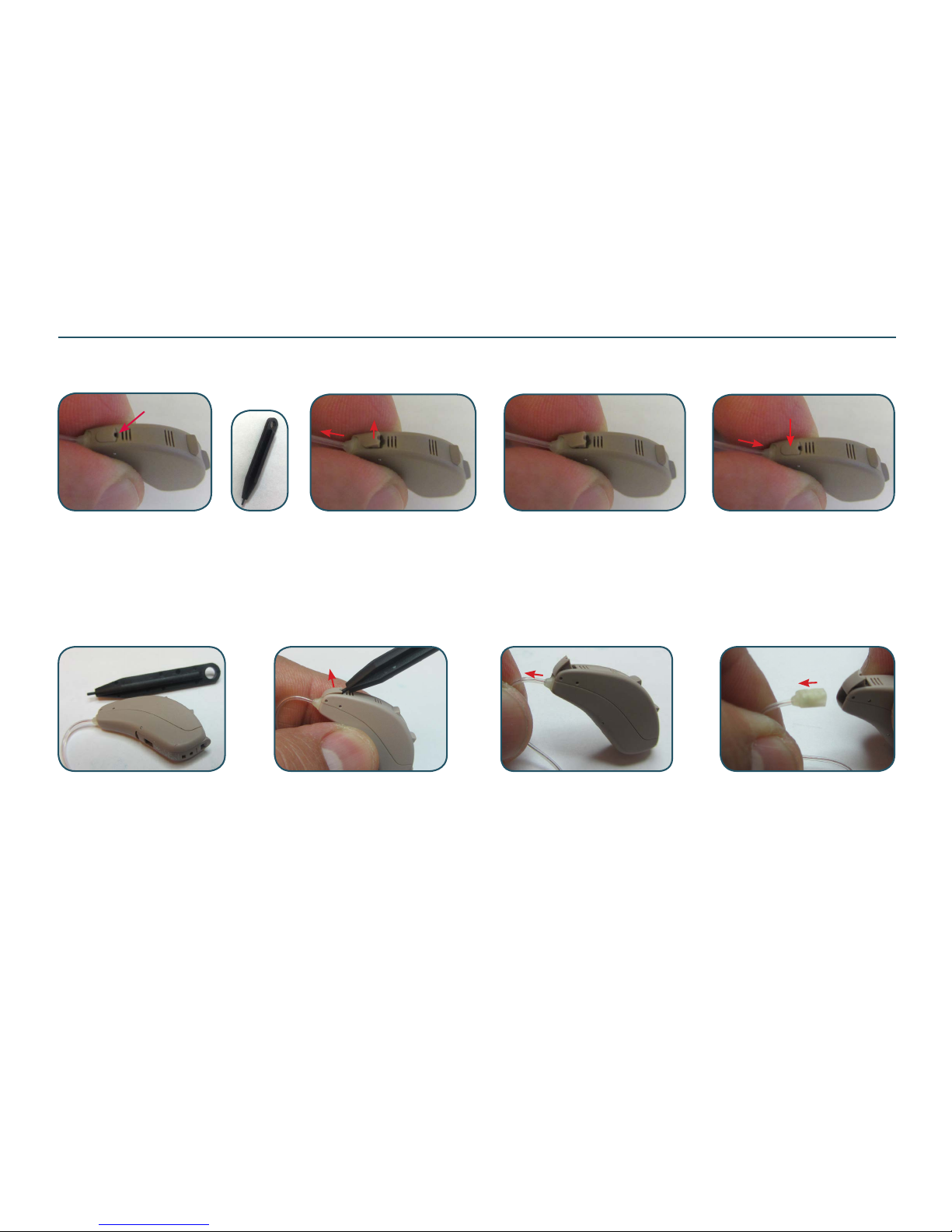
Replacing Receiver Tube
The connector lock is holding the rec tube in place. Lift it up using the plastic mandrel and pull out the rec tube. Push in a new rec tube and make sure
it is correct in place. Press down the conn lock to x the rec
CRISP & SHARE:
STEP:
The connector lock is mounted to the top HSG together with the TGL. It is holding the rec tube in place. Lift up the conn lock using the mandrel and
pull out the rec tube. Push in a new rec tube and make sure it is correct in place. Press down the conn lock to x the rec. If the conn lock is damaged,
a new assembled top HSG must be mounted
Note:
Receiver test tpix available on GTO web site
Page 26

Doc 0219660 rev. K
Page 26 of 32
Not subject to issue control when printed
Service Procedure & Postponement
Service Procedure:
- Save user settings with Fitting Software
- Disassemble faulty device
- Replace module with a new service module from stock
- Assemble device
- Restore user settings with Fitting Software
- Load customer serial No using DSA6000
Postponement Procedure:
- Disassemble device
- Replace parts with replacement kit/HSG parts from stock
- For Crisp & Share models: Transfer ID-plate from old housing to new housing
- Verify battery door by open and close once
Page 27
Doc 0219660 rev. K
Page 27 of 32
Not subject to issue control when printed
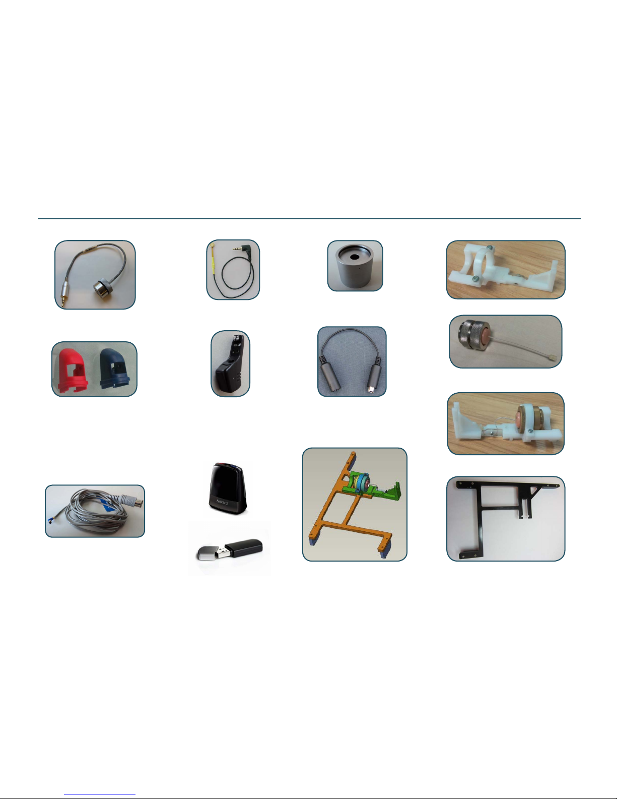
Batt pill size 312 must
be used during test
p/n 17449300
Test Equipment (3 pin)
TEST JIG p/n 19429000
Test frame p/n 16902800
CS44 Prog cable
(Left blue is shown)
9022 907 69019 (R)
9022 907 69029 (L)
P/n 17517800
Prog cable ext must be used during
HI test due to current measurement
(not needed when using tting SW)
Prog adapt generic
p/n 18041400
(incl guide & clips)
2cc coupler p/n 30-4838800
can be ordered with GTO
Dept/HQ Ballerup DK
Prog adapt clip - recommended
to be used during test procedures
17736900 Red
17736901 Blue
(used w prog adapt 18041400)
COUPL MIC,TM-12,MEASURED
p/n 18220700
ASM TEST REC UP 3 PIN
p/n 20011700
P/n 17292002
AIRLINK 2
JIG,TEST,BERLIN RIE,W/UP REC
p/n 19454400
Both airlinks can be
used for wl conn test
P/n 19429100
TEST JIG,BRIE W BASE & REC
P/n 17292000
Airlink
Page 28
Doc 0219660 rev. K
Page 28 of 32
Not subject to issue control when printed
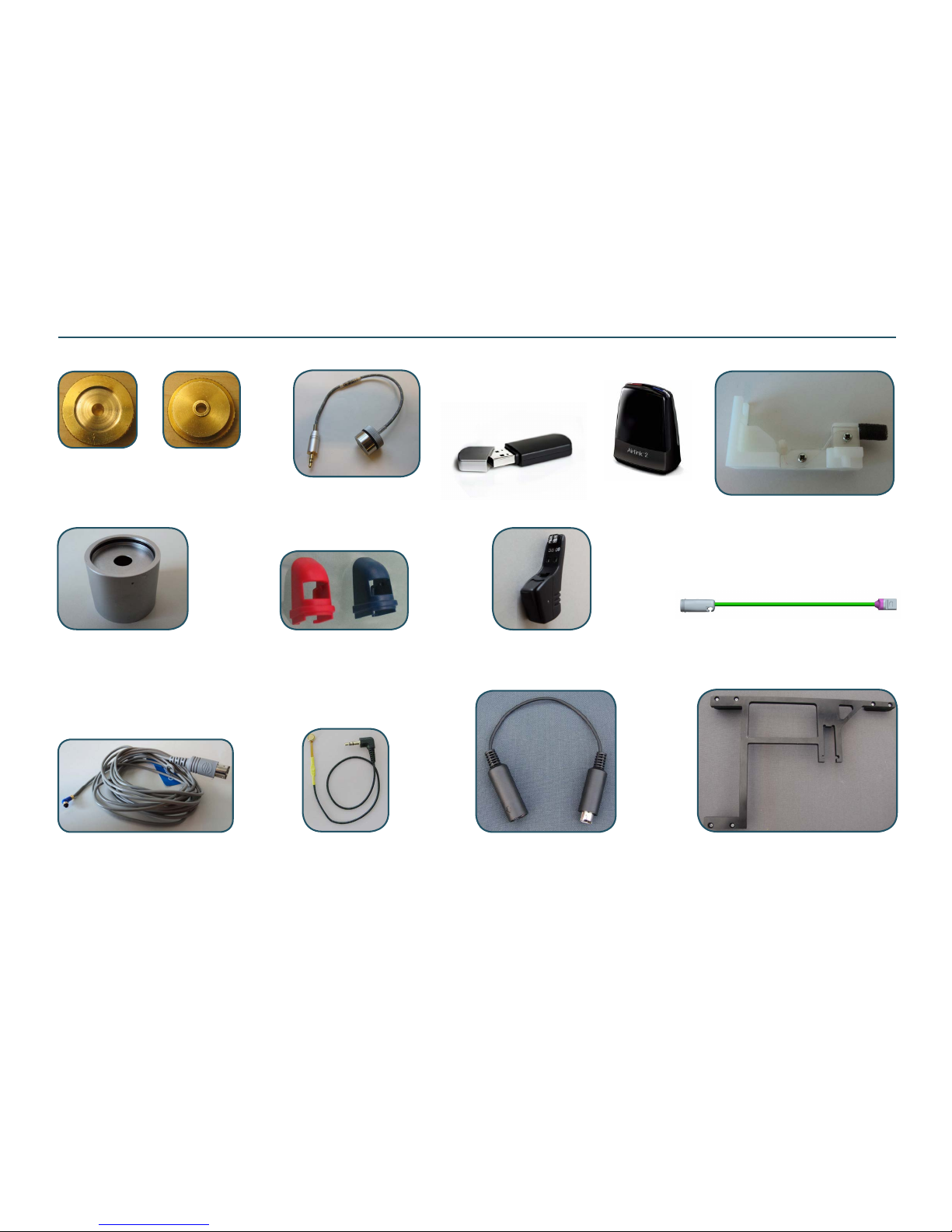
Test Equipment for HI with 2 Pin rec
Instrument xture
p/n 17850700 (incl test rec)
Coupler Insert (brass) to be attached
2cc coupler during nal HI test
p/n 16169300
(shown from both sides)
Batt pill size 312
p/n 17449300
must be used
during test
Test frame p/n 16902800
Test Rec (NP)
p/n 17460000 for HI testing
CS44 Prog cable
(Left blue is shown)
9022 907 69019 (R)
9022 907 69029 (L)
2cc coupler
p/n 30-4838800
to be ordered with GTO
Dept/HQ Ballerup DK
Prog adaptor clip
17736900 Red
17736901 Blue
Prog adaptor
p/n 18041400
(incl 1 x red & 1 x blue clip)
P/n 17517800
Prog cable ext must be used during
HI test due to current measurement
(not needed when using tting SW)
P/n 17292000
Airlink to be used for
wireless “Connection test”
Both airlinks can be used for wl
connection test
17292002 AIRLINK 2
Coupler mic,TM-12 measured
p/n 18220700
Page 29
Doc 0219660 rev. K
Page 29 of 32
Not subject to issue control when printed
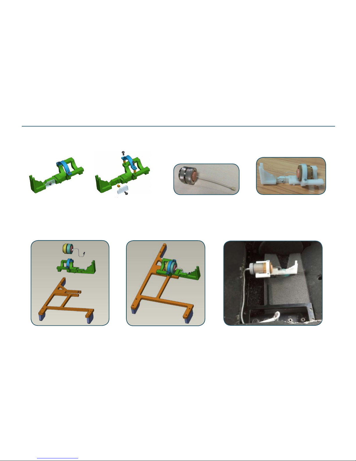
Prepare for HI Test (3 pin)
Page 30
Doc 0219660 rev. K
Page 30 of 32
Not subject to issue control when printed
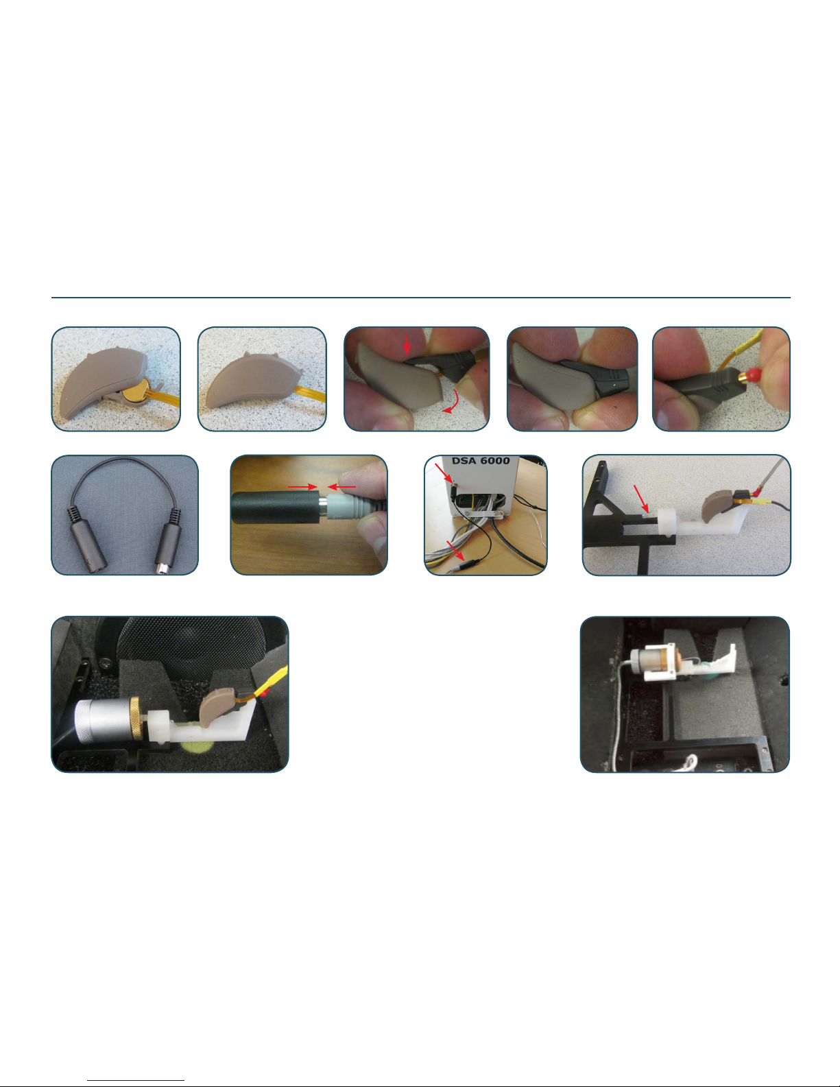
HI Testing
Important note: An extension prog cable must be used during nal HI test due to the current measur-
ing. Connect prog cable to the extension prog cable and connect extension cable to the DSA6000
Pull out the rec tube. Open the batt door as described on the previous page and insert the batt pill. Connect the prog adapt and prog cable to the HI
Insert the test rec into HI and attach the HI
to the white xture (2 pin rec is shown)
Test Rec (NP)
p/n 17460000
Extension
prog cable
Mount the 2cc coupler to the TM12 coupler mic. Attach
the brass adapt to the 2cc coupler. Insert the 2 pin test
rec to the brass DSA adapt (the 3 pin test rec is already
inserted a DSA adapt). Attach the xture to the black test
frame and place it all in the test chamber as shown. Select the correct test prog and make sure to follow instructions coming up on the screen
ATC4000 sound chamber prepared
for test of HI with 2 pin rec
Please see page “Test Equipment (3 pin)” for info
about test parts to be used for 3 pin rec models
ATC4000 sound chamber prepared
for test of HI with 3 pin rec
Page 31
Doc 0219660 rev. K
Page 31 of 32
Not subject to issue control when printed
Prog Adaptor Clip
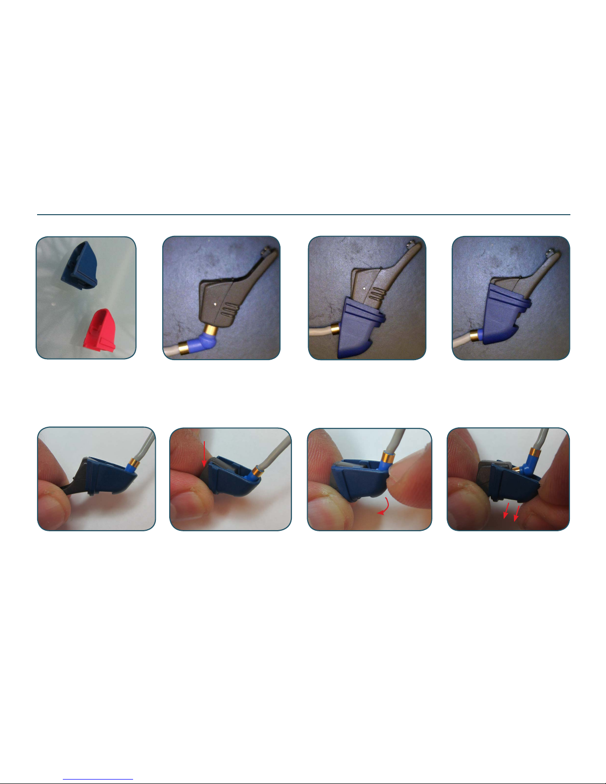
To remove the clip rmly grip this side of prog adapt Pull tip of the clip Slide the clip from adaptor
It is important to have the programming cable connected before adding the clip to the programming adaptor.
Add the clip as shown in the pics. The clip is recommended to be used during test / tting in order to keep the
prog cable connected during the complete procedure
Clip for prog adaptor L/R
Page 32
Doc 0219660 rev. K
Page 32 of 32
Not subject to issue control when printed
Wireless Test - Connection Test
Wireless test using Airlink / Airlink 2:
The “RF (Radio Frequency) signal test” is performed during hybrid test. In service & repair situations only a connection test is needed.
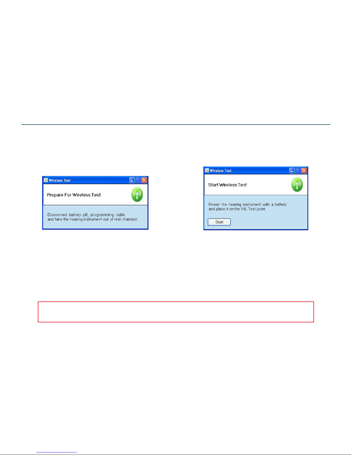
The DSA6000 can perform a connection test to test the wireless function on the devices. The test is performed using an Airlink / Airlink
2 mounted directly in any of the DSA 6000 units USB ports. No xture is required performing a Connection test
The test is performed in the open air on the desktop.
During a DSA6000 test prog running the connection test
the operator will be asked to place the device in the WL
Test point. During the connection test the device does
not need to be connected with a prog cable and a batt
pill. Instead a fresh batt must be inserted. The connection test is a part of the Final Device Test running on the
DSA 6000. The test system will search for a device with
a s/n matching the s/n for the Device Under Test (DUT)
in the running test sequence
To make sure the device is in boot mode the batt must be
inserted immediately before the [Start] button is pressed.
The WL Test point is a spot on the table approx 20 cm
away from the Airlink dongle. The s/n matching will prevent connection with any other wireless devices in the
nearby area. Best practice is to rst insert the battery
and immediately after press the Start button (within 5
sec). Inserting the batt will start the device boot sequence
Note:
An extended wireless test using a TV streamer / SAS is introduced. Please nd more detailed info in Tech Bulletin No. 2013-05-002 “Improved functionality for the RF Range check on DSA 6000” on GTO web site where also other info about wireless test can be found
 Loading...