

Inter-Tel EncoreCX, Encore ECX 2000, Encore ECX 1000, Encore ECX 1000W Installation And Maintenance Manual
Page 1
Page 2

Inter-Tel EncoreCX
Installation & Maintenance Manual
1
Table of Contents
TABLE OF CONTENTS.......................................................................................................................................................1
FCC INFORMATION...........................................................................................................................................................5
SAFETY REGULATIONS ...................................................................................................................................................8
LIMITED WARRANTY....................................................................................................................................................10
SOFTWARE LICENSE AGR EEMENT.......................................................................................................................11
INTRODUCTION ................................................................................................................................................................ 14
GENERAL OVERVIEW ...................................................................................................................................................14
SAFETY PRECAUTIONS DURING INSTALLATION AND SYSTE M UPGRADES....................................................................14
ELECTROSTATIC PRECAUTION (ESP)................................................................................................................................15
LIGHTNING AND SURGE VOLTAGE PROTECTION..............................................................................................................15
EQUIPMENT LIST ..................................................................................................................................................................15
INSTALLATION STEPS...........................................................................................................................................................17
INSTALLING THE MAIN EQUIPMENT...................................................................................................................18
EQUIPMENT LOCATION........................................................................................................................................................18
MOUNTING THE CCU ..........................................................................................................................................................18
MODULES LOCATED IN THE CCU...........................................................................................................................21
MODULE LOCATION.............................................................................................................................................................21
SYSTEM EXPANSION ......................................................................................................................................................22
INSTALLING THE BACKPLANE WALL BRACKE T................................................................................................................22
MOUNTING THE CCU WITH TWO BRACKETS...................................................................................................................22
MOUNTING THE BACKPLANE..............................................................................................................................................23
EXPANSION MODULES ..................................................................................................................................................24
REMOVING THE 008 MODULE FROM THE BACK PLANE....................................................................................................25
INSTALLING THE 008 MODULE ONTO THE BACKPLANE ..................................................................................................26
INSTALLING AN EXPANSI ON MODULE................................................................................................................................26
CO LINE MODULE................................................................................................................................................................27
EXTERNAL MUSIC-ON-HOLD MODULE...............................................................................................................31
T1/PRI MODULE ................................................................................................................................................................31
CONNECTING THE BATTERY-BACKUP-UNIT (BBU) TO THE SYSTEM................................................32
CONNECTING THE BATTERY ....................................................................................................................................33
EXTENSIONS.......................................................................................................................................................................34
ECX 2000 DIGITAL TELEPHONE SET.................................................................................................................................34
ECX 1000/ ECX 1000W DIGITAL TELEPHONE...............................................................................................................35
DIRECT S TATION SELECTION (DSS) UNIT ........................................................................................................................37
CLIP , PEDESTAL AND INSTALLATION OF THE DSS..........................................................................................................38
WALL-MOUNTING AN ECX 1000 OR ECX 2000 TELEPHONE.......................................................................................39
Page 3

Inter-Tel EncoreCX
Installation & Maintenance Manual
2
DOOR PHONE ........................................................................................................................................................................40
V-2904 VALCOM ANS WERING SYSTEM INSTALLATION ................................................................................................41
CABLING THE UNIT........................................................................................................................................................44
CONNECTING THE EXTENS IONS..........................................................................................................................................45
CONNECTING T1 / PRI TRUNKS.........................................................................................................................................45
STRUCTURED WIRING..........................................................................................................................................................47
CCU CONNECTIONS.............................................................................................................................................................48
DOOR PHONE ........................................................................................................................................................................48
DOORSTRIKE.........................................................................................................................................................................48
CONNECTING A PA (PUBLIC ADDRESS) AMPLIFIER........................................................................................................48
CONNECTING A PC OR PRINTER TO THE SERIAL PORT...................................................................................................49
CENTRAL BELL.....................................................................................................................................................................49
EXTENSION MODULE MDF CONNECTIONS......................................................................................................................49
IP ROUTER MODULE CONNECTIONS....................................................................................................................50
EXPANDING AN EXISTIN G SYSTEM.......................................................................................................................51
INSTALLING AN ADDITIONAL CO LINE MODULE............................................................................................................51
INSTALLING ADDITIONAL EXTENSION MODULES OR AN IP ROUTER MODULE..........................................................51
T1 / PRI ON THE ENCORECX.......................................................................................................................................52
TI (RBS) SETTINGS.............................................................................................................................................................52
FRAMING AND CODING ON T1 (RBS) ...............................................................................................................................53
LINE BUILD OUT ..................................................................................................................................................................53
LINE G AIN.............................................................................................................................................................................53
DTMF OR PULSE DIALING..................................................................................................................................................53
RECEIVED DIGITS.................................................................................................................................................................53
PROGRAMMING REQUIRED FOR PRI (ISDN)....................................................................................................................54
PROGRAMMING THE Q 931 PROTOCOL ON PRI (ISDN).................................................................................................54
LINE BUILD OUT PROGRAMMING ON PRI (ISDN) ..........................................................................................................54
LINE G AIN PROGRAMMING FOR PRI (ISDN) ...................................................................................................................54
ADDITIONAL PROGRAMMING OPTIONS FOR PRI (ISDN) ................................................................................................54
ADDITIONAL PRI (ISDN) INFORMATION .............................................................................................................55
ISDN (PRI) CALLED PARTY NUMBER - CALL TYPES....................................................................................................55
ISDN (PRI) CALLING PARTY NUMBER - CALL TYPE....................................................................................................56
DIALING NUMBERS ON ISDN (PRI)...................................................................................................................................56
CALLER ID RESTRICTION OVERRIDE.................................................................................................................................56
TRANSIT NETWORK SELECTION ON ISDN (PRI).............................................................................................................56
RELEASE COMPLETE ............................................................................................................................................................56
T1/ PRI DIAGNOSTICS ....................................................................................................................................................57
ALARM INDICATIONS ...........................................................................................................................................................57
DMS EXCHANGE – LT1 FLAG ...........................................................................................................................................58
MAINTENANCE PROCEDUR ES..................................................................................................................................59
HOT SWAPPING FAULTY MODULES....................................................................................................................................59
REPLACING A FAULTY MODULE MDF...............................................................................................................................60
REPLACING FAULTY PCB S .........................................................................................................................................61
REPLACING THE 008 EXTENSION BOARD..........................................................................................................................61
POWER SUPPLY UNIT SPARE FUSE......................................................................................................................................63
REPLACING THE CCU MDF ...............................................................................................................................................64
POWER FAILURE..............................................................................................................................................................65
Page 4

Inter-Tel EncoreCX
Installation & Maintenance Manual
3
POWER UP AND TEST.....................................................................................................................................................66
SWITCH ON............................................................................................................................................................................66
GETTING STARTED.........................................................................................................................................................66
ESSENTIAL PROGRAMMING......................................................................................................................................67
EQUIPPED CO LINES ............................................................................................................................................................67
INCOMING RINGING..............................................................................................................................................................67
CALL RESTRICTION ..............................................................................................................................................................67
INDIVIDUAL DIGITAL TELEPHONE SET PROGRAMMING........................................................................68
SYSTEM PROGRAMMING FROM THE PROGRAMMING TELEPHONE................................................. 71
“SYSTEM” PROGRAMMING OPTIONS.................................................................................................................................73
“EXTENSIONS” PROGRAMMING OPTIONS..........................................................................................................................76
“LINES” PROGRAMMING OPTIONS......................................................................................................................................78
“SYSTEM” PROGRAMMING........................................................................................................................................79
TIME AND DATE...................................................................................................................................................................79
TO CHANGE THE SYSTEM PROGRAMMING PASSWORD..................................................................................................79
TO CHANGE THE PROGRAMMING EXTENSION.................................................................................................................80
NIGHT SERVICE....................................................................................................................................................................80
MUSIC-ON-HOLD OPTIONS.................................................................................................................................................81
TO CONFIGURE LINE KEY LIGHTS.....................................................................................................................................81
CHANGE GREETINGS............................................................................................................................................................81
PROGRAMMING SYSTEM TIMERS.......................................................................................................................................83
LOCAL CODES.......................................................................................................................................................................86
TO RESET THE SYSTEM .......................................................................................................................................................86
ENHANCED EMERGENCY SERVICE E911 ..........................................................................................................................88
EXTENSION PROGRAMMING ....................................................................................................................................90
ASSIGNING EXTENSION NAMES.........................................................................................................................................90
TO CONFIGURE DISCONNECTED EXTENSIONS.................................................................................................................92
LINE PROGRAMMING..................................................................................................................................................101
OUTGOING G ROUPS...........................................................................................................................................................104
PROGRAMMING THE SERVICE TYPES..............................................................................................................................111
DID LINE TYPE - SERVICE TYPES...................................................................................................................................112
LOOP S TART LINE TYPE - SERVICE TYPES.....................................................................................................................112
GROUND S TART LINE TYPE - SERVICE TYPES...............................................................................................................112
PROGRAMMING THE S TART TYPES..................................................................................................................................112
IP ROUTER MODULE PROGRAMMING...............................................................................................................117
SETTING UP AN ADSL INTERNET CONNECTION VIA AN EXTERNAL MODEM...........................................................122
RECOMMENDATIONS FOR CUSTOMER TRAINING.....................................................................................125
TROUBLESHOOTING....................................................................................................................................................126
SYSTEM NOT INITIALIZI NG................................................................................................................................................126
NO INCOMING CALLS .........................................................................................................................................................126
EXTENSION OUTGOING LO CKED.......................................................................................................................................126
NO EXTENSION DIAL TON E................................................................................................................................................126
NOT SEIZING A LINE FOR OUTGOING CALLS....................................................................................................................126
DOOR PHONE NOT OPERATING.........................................................................................................................................126
PHONE RESET ......................................................................................................................................................................126
Page 5

Inter-Tel EncoreCX
Installation & Maintenance Manual
4
SYSTEM RESET....................................................................................................................................................................126
ADDITIONAL TROUBLESHOOTING INFORMATION ..........................................................................................................126
SOFTWARE UPGR ADE INSTRUCTIONS ..............................................................................................................133
UPGRADING SYSTEMS AN D RESTORING DATABASES WHEN UPGRADING TO T1/PRI............134
SOFTWARE VERSIONS / FEATURE CHANGES .................................................................................................135
FEATURES PROVIDED BY SOFTWARE V ERSION 457......................................................................................................135
FEATURES PROVIDED BY SOFTWARE VERSION 533 .......................................................................................................135
TECHNICAL SPECIFICATION..................................................................................................................................136
INDEX ...................................................................................................................................................................................138
Page 6

Inter-Tel EncoreCX
Installation & Maintenance Manual
5
FCC INFORMATION
FCC Part 68 Exhibit J
This equipment complies with Part 68 of the FCC rules and the requirements adopted by the ACTA. On the
exterior of the cabinet of this equipment is a label that contains, among other information, a product identifier in
the format LKCPF09BENCORECX. If requested, this number must be provided to the telephone company.
• FCC Registration Number: LKCPF09BENCORECX
• Ringer Equivalence Number (REN): 0.9B
• Facility Interface Code (FIC): 9.0Y
• Service Order Code (SOC): 02LS2
• USOC Jack Type: RJ11
A FCC compliant telephone cord and modular plug is provided with this equipment. This equipment is designed
to be connected to the telephone network or premises wiring using a compatible modular jack that is Part 68
compliant. See Installation Instructions for details.
The REN is used to determine the quantity of devices that may be connected to the telephone line. Excessive
RENs on the telephone line may result in the devices not ringing in response to an incoming call. Typically, the
sum of RENs should not exceed five (5.0). To be certain of the number of devices that may be connected to a
line (as determined by the total RENs) contact the local telephone company.
If this equipment ENCORE CX causes harm to the telephone network, the telephone company will notify you in
advance that temporary discontinuance of service may be required. But if advance notice isn't practical, the
telephone company will notify the customer as soon as possible. Also, you will be advised of your right to file a
complaint with the FCC if you believe it is necessary.
The telephone company may make changes to its facilities, equipment, operations or procedures that could affect
the operation of the equipment. If this happens the telephone company will provide advance notice so you can
make the necessary modifications to maintain uninterrupted service.
If trouble is experienced with this equipment ENCORECX, for repair or warranty information, please contact
Inter-Tel Technical Support Department, 7300 West Boston Street, Chandler, Arizona, 85226, Tel: 1-888-777EASY (3279). If the equipment is causing harm to the telephone network, the telephone company may request
that you disconnect the equipment until the problem is resolved.
Connection to party line service is subject to state tariffs. (Contact the state public utility commission, public
service commission or corporation commission for information.)
CAUTION
THE TELEPHONE INSTRUMENTS SPECIFICALLY DESIGNED FOR THIS SYSTEM
HAVE HEARING-AID COMPATIBLE HANDSETS THAT ARE IN COMPLIANCE WITH
SECTION 68.316 OF THE FCC RULES.
Page 7
Inter-Tel EncoreCX
Installation & Maintenance Manual
6
Customer Owned Coin/Credit Card Phones
To comply with state tariffs, the telephone company must be given notification prior to connection. In some
states, the state public utility commission, public service commission or corporation commission must give prior
approval of connection.
Data Equipment
The table below shows which jacks are associated with which modes of operation:
Mode of Operation
USOC Jack
Permissive RJ11C
Programmable RJ41S and RJ45S
Systems
Facility Interface Codes (FIC), Service Order Codes (SOC), USOC Jack Codes and Ringer Equivalence
Numbers (REN) are shown in the table below for each port where applicable:
Port FIC SOC USOC Jack REN
PSTN 9.0Y 02LS2 RJ11 0.9B
ISDN _PRI RJ45
ADSL RJ11
Adjuncts – KX and PX Devices
When this adjunct is used with a leased system, permission of the owner should be requested for connection of
the adjunct.
KX-type telephones with message waiting lights and/or line status indicators can only be connected to host
equipment and never directly to the network.
KX devices can only be installed with the permission of the owner of the host equipment as “surgery” is often
required on the host system.
OEM Devices
The mounting of the certified unit in the final assembly must be made so that the certified unit is isolated from
exposure to any hazardous voltages within the assembly. Adequate separation and restraint of cables and cords
must be provided.
The circuitry from the certified unit to the telephone line must be provided in wiring that carries no other
circuitry unless specifically allowed by the rules (such as PC and PR leads). PC board traces carrying tip and
ring leads shall have sufficient spacing to avoid surge breakdown.
If the certified device is enclosed in an assembly, and is not readily accessible, the certification label must be
placed on the exterior of the cabinet for each type of certified device contained therein.
The final assembler must provide all applicable material (contained in this section) with the final equipment.
A modular plug or jack must be provided which complies with Part 68, Subpart F requirements for dimensions,
tolerances and metallic plating.
Page 8

Inter-Tel EncoreCX
Installation & Maintenance Manual
7
WARNING
This equipment generates and uses radio frequency energy and if not installed and used properly, that is, in strict
accordance with the manufacturer's instructions, may cause interference to radio and television reception. It has
been type tested and found to comply with the limits for a Class A computing device in accordance with the
specifications in Subpart J of Part 15 of FCC Rule. Operation of this equipment in a residential area may cause
unacceptable interference to radio and TV reception requiring the operator to take whatever steps are necessary
to correct the interference. However, there is no guarantee that interference will not occur in a particular
installation. If this equipment does cause interference to radio or television reception, which can be determined
by turning the equipment off and on, the user is encouraged to try to correct the interference by one or more of
the following measures:
• Reorient the receiving antenna
• Relocate the CCU with respect to the receiver
• Check that the CCU and receiver are not on the same circuit; the CCU must be powered from an isolated,
dedicated AC outlet
If necessary, the user should consult the dealer or an experienced radio/television technician for
additional suggestions. The user may find the following booklet prepared by the FCC helpful: “How to
Identify and Resolve Radio-TV Interference Problems”
This booklet is available from the U.S. Government Printing Office, Washington, D.C. 20402, Stock No.
004-000-00398-5. If RFI problems persist, contact Inter -Tel Customer Support.
Page 9

Inter-Tel EncoreCX
Installation & Maintenance Manual
8
Safety Regulations
Important Safety Instructions
The following safety information is reprinted from UL 1459. When using your telephone equipment, basic safety
precautions should always be followed to reduce the risk of fire, elec tric shock, and injury to persons, including
the following:
1. Read and understand all instructions.
2. Follow all warnings and instructions marked on the product.
3. Unplug this product from the wall outlet before cleaning. Do not use liquid cleaners or aerosol cleaners.
Use a damp cloth for cleaning.
4. Do not use this product near water (for example, in a wet basement).
5. Do not place this product on an unstable cart, stand, or table. The product may fall, causing serious
damage to the product.
6. Slots and openings in the cabinet and the back or bottom are provided for ventilation, to protect it from
overheating; these openings must not be blocked or covered. This product should never be placed near or
over a radiator or heat register. This product should not be placed in a built -in installation unless proper
ventilation is provided.
7. This product should be operated only from the type of power source indicated in the manual. If you are
not sure of the type of power source to your building, consult your dealer or local power company.
8. This product is equipped with a three-wire grounding type plug, a plug having a third (grounding) pin.
This plug will only fit into a grounding type power outlet. This is a safety feature. If you are unable to
insert the plug into the outlet, contact your electrician to replace your obsolete outlet. Do not defeat the
safety purpose of the grounding type plug.
9. Do not allow anything to rest on the power cord. Do not locate this product where the cord will be abused
by persons walking on it.
10. Do not use an extension cord with this product's AC power cord. The AC outlet for this product should
not be used for any other electrical equipment.
11. Never push objects of any kind into this product through cabinet slots as they may touch dangerous
voltage points or short out parts that could result in a risk of fire or electric shock. Never spill liquid of
any kind on the product.
12. To reduce the risk of electric shock, do not disassemble this product, but take it to a qualified serviceman
when some service or repair work is required. Opening or remov ing covers may expose you to dangerous
voltages or other risks. Incorrect reassemble can cause electric shock when the product is subsequently
used.
13. Unplug this product from the wall outlet and refer servicing to qualified service personnel under the
following conditions:
• When the power supply cord or plug is damaged or frayed.
• If liquid has been spilled into the product.
• If the product has been exposed to rain or water.
• If the product does not operate normally by following the operating instructions.
• Adjust only those controls that are covered by the operating instructions because improper adjustment
of other controls may result in damage and will often require extensive work by a qualified technician
to restore the product to normal operation.
• If the product has been dropped or the cabinet has been damaged.
Page 10

Inter-Tel EncoreCX
Installation & Maintenance Manual
9
• If the product exhibits a distinct change in performance.
14. Avoid using a telephone (other than a cordless type) during an electrical storm. There may be a remote
risk of electric shock from lightning.
15. Do not use the telephone to report a gas leak if the telephone is in the vicinity of the leak.
Save These Instructions
Page 11

Inter-Tel EncoreCX
Installation & Maintenance Manual
10
Limited Warranty
For a period of 18 months from the date of purchase, INTER-TEL warrants the Equipment (except for fuses and
lamps) to be free from defects in material, workmanship, or both, and to comply with specifications for the
Equipment, as set forth in the Installation Manual . Buyer's sole and exclusive remedy for breach of this Limited
Warranty shall be to have the defective Equipment (or parts) repaired or replaced at INTER-TEL's option.
Shipping costs incurred returning warranty work to INTER-TEL shall be paid for by the Buyer. This Limited
Warranty extends only to the Buyer, not to any customer, user, or third party. This Limited Warranty does not
apply to Equipment (or parts) damaged by improper handling, normal wear and tear, accidents, lightning
damage, negligence, or improper use or maintenance, and does not apply to Equipment altered without
authorization by INTER-TEL. This Limited Warranty does not extend to any claims, suits, damages, liabilities,
costs, and expenses arising from any act, action, or inaction of Buyer. Although the Moss -Magnuson Act should
not apply, in the event that it is held to apply by a court of competent jurisdiction, the implied warranty of fitness
for a particular purpose shall extend for the 18-month period from the date that the Equipment was purchased.
NOTE: THIS WARRANTY IS IN LIEU OF AND EXCLUDES ALL OTHER WARRANTIES, EXPRESS OR
IMPLIED, INCLUDING, BUT NOT LIMITED TO, THE IMPLIED WARRANTY OF MERCHANTABILITY OR
FITNESS FOR A PARTICULAR PURPOSE. THERE ARE NO WARRANTIES WHICH EXTEND BEYOND THIS
LIMITED WARRANTY. IN NO EVENT SHALL INTER-TEL BE LIABLE FOR LOSS OF ANTICIPATED
PROFITS, INCIDENTAL OR CONSEQUENTIAL DAMAGES, LOSS OF TIME OR OTHER LOSSES
INCURRED BY BUYER IN CONNECTION WITH THE PURPOSE, POSSESSION, OPERATION, OR USE OF
THE EQUIPMENT, SUCH CLAIMS BEING EXPRESSLY WAIVED BY THE INSTALLING COMPANY.
CAUTION
For complete information on returning equipment, refer to the current Inter-Tel Repair and Return Policy
(document part no. 835.1065). This document includes specific information on the following subjects:
warranty, procedures to follow when returning equipment, equipment damaged in shipment, insurance,
repair policy, and advance replacement policy.
Page 12

Inter-Tel EncoreCX
Installation & Maintenance Manual
11
Software License Agreement
THE FOLLOWING IS A SITE LICENSE AGREEMENT RELATING TO THE INTER-TEL SOFTWARE.
PLEASE CAREFULLY READ ALL OF THE TERMS AND CONDITIONS BEFORE PROCEEDING. THE
SOFTWARE REFERENCED HEREIN IS LICENSED IN ACCORDANCE WITH THE FOLLOWING
TERMS AND CONDITIONS. IF YOU DO NOT ACCEPT SUCH TERMS AND CONDITIONS YOU WILL
NOT BE PERMITTED TO USE THE SOFTWARE. IF YOU ACCESS OR USE SUCH SOFTWARE IN
CONTRAVEN TION OF THE TERMS AND PROVISIONS OF THIS AGREEMENT, YOU WILL BE SUBJECT TO PROSECUTION TO THE FULLEST EXTENT PERMITTED BY LAW.
Definitions:
“You” means, and “Yours” refers to the original end user purchaser of the Inter-Tel Software Programs.
“Computer” means a computer consisting of a single central processing unit, one keyboard and one video
display terminal. “Inter-Tel Hardware System” means any proprietary system dis tributed by Inter-Tel Integrated
Systems (hereinafter “Company” or “Inter-Tel”) that operates by means of the Software. “Authorized Dealer”
means an individual or entity currently authorized in writing by agreement and in good standing with Inter-Tel
entitling the dealer to sell or license the specific Software covered by this license. “Software” means: the
computer programs accompanying this License (including, but not limited to, codes, techniques, software tools,
formats, designs, methods, processes, know-how and ideas) and any and all copies, modifications, upgrades,
enhancements and new releases thereof made or acquired by You and any and all manuals and other printed
materials accompanying this License or the Software.
License:
(a) Inter-Tel Integrated Systems, Inc. (“Inter-Tel”) grants You a non-exclusive, non-transferable license to
install and use the enclosed Inter-Tel Software and accompanying documentation on any one
standalone personal computer or Inter-Tel Hardware System (whichever applies). You assume the
entire responsibility for the selection and installa tion of the enclosed Software program(s) in order to
achieve desired results. You agree that you are licensing the Program for its end use only and not for
resale or redistribution. You must be an Authorized Dealer of the specific Inter-Tel products covered by
this license. You will be liable for theft and infringement under applicable patent, copyright and
trademark laws of the United States for unauthorized use of the Software covered by this license.
Inter-Tel reserves all rights in and to all patents, copyrights, trademarks, mask works and any other
proprietary rights contained or embodied in the Software.
(b) You may make one (1) copy of the Inter-Tel Software program(s) contained on dis kette(s) for back-up
purposes only, provided that You reproduce and place the Inter-Tel copyright notice on the backup
copy. You may make one (1) copy of the Software program(s) onto one (1) hard drive. You may not
copy the Inter-Tel Software program(s) contained on any media other than diskette; e.g., hard disk
drive, ROMs, PALs, Software Protection Key, etc.
(c) You are hereby notified that contained third -party suppliers and vendors are third -party beneficiaries to
this Agreement to the extent that the Software contains software, programming and other materials
provided by such third -party suppliers and vendors. Such provisions are made expressly for the benefit
of and are enforceable by such third-party suppliers and vendors in addition to Inter -Tel.
(d) You hereby acknowledge and agree that the license granted in this agreement is a site license. I.e., the
software may only be installed at the initial end user site licensed for this software and at no other site
without the express written consent and relicensing by Inter-Tel Integrated Systems, Inc. You
acknowledge and agree that you have the responsibility to sublicense the end user of the software with
Page 13

Inter-Tel EncoreCX
Installation & Maintenance Manual
12
an agreement in writing containing the statement that “the software licensed hereby may only be
installed at the initial end user site licensed for this software and at no other site without the express
written consent and relicensing by Inter-Tel Integrated Systems, Inc.” It is the specific intent of this site
licensing agreement to (1) prohibit the improper copying and/or the multiple use of this software at
other than a designated initial licensed site, and to (2) prohibit the right of resale and/or relicensing of
the software without the express written consent of Inter-Tel. You agree that your failure to properly
sublicense the software to an end user will subject you to responsibility for the losses occasioned to
Inter-Tel.
Non-Permitted Uses:
(a) You may not use the enclosed program(s) on more than one standalone personal computer or Inter-Tel
Hardware System at a time and may not load the Software onto any file server or network.
(b) You may not sublicense, assign or transfer Your rights under the Agreement without the prior written
permission of Inter -Tel.
(c) You may not use, copy, alter or transfer, electronically or otherwise, the Inter-Tel Soft ware (program(s) or
documentation) except as expressly allowed in this Agreement.
(d) You may not translate, reverse engineer, disassemble or decompile the Inter-Tel Software.
(e) You agree that you are licensing the Program for its end use only and not for resale or redistribution.
Term:
This Agreement is effective from Your date of purchase and shall remain in force until termi nated. You may
terminate the Agreement by returning to Inter-Tel the original diskette(s), ROMs, or other applicable software
media and all copies of the Inter-Tel software program(s). The Agreement is also terminated if You fail to
comply with any term or condition of this Agreement. You agree to return to Inter -Tel the original diskette(s) and
other applicable software media and all copies of the Inter-Tel Software program(s) upon such termination. The
Company may immediately terminate this license upon notice to you, whereupon you shall immediately destroy
all copies of the Program.
Warranty:
(a) Inter-Tel warrants to You that the diskette(s), and/or other applicable software media on which the Inter-Tel
Software program(s) are furnished are not defective under normal use for a period of ninety (90) days from
the date of purchase, as evidenced by a copy of Your sales receipt.
(b) Inter-Tel and its third-party suppliers and vendors’ liability and Your exclusive remedy shall be the
replacement of any diskette(s) and/or other applicable software media that do not meet the warranty and
which are returned to Inter-Tel or an authorized dealer together with a copy of Your paid receipt. THE
ABOVE IS THE ONLY WARRANTY OF ANY KIND. ALL OTHER WARRANTIES EITHER EXPRESS
OR IMPLIED, INCLUDING, BUT NOT LIMITED TO, THE IMPLIED WARRANTIES OF
MERCHANTABILITY AND FITNESS FOR A PARTICULAR USE ARE HEREBY DISCLAIMED. This
warranty gives You specific legal rights and You may also have other rights which may vary from state to
state.
You acknowledge that the Program, including the related documentation and any new releases, modifications and
enhancements thereto, belongs to the Company, and that the Company retains all right, title and interest in and to
the Program. You further acknowledge that the Program and information relating thereto constitute valuable trade
secrets of the Company. You agree to comply with the terms and conditions of this Agreement and agree to treat
the Program as the confidential and proprietary information of the Company.
You shall be solely responsible for the supervision, management and control of your use of the Program and
Page 14

EncoreCX
Installation and Maintenance Manual
13
related products and documentation. You hereby indemnify and hold harmless the Company and its affiliates (the
Indemnified Parties) against any loss, liability, damages, costs or expenses suffered or incurred by the
Indemnified Parties at any time as a result, of any claim, action or proceeding arising out of or relating to your
use, operation or implementation of the Program. For purposes of this Agreement, affiliate means any Company
division or subsidiary or any other affiliated entity involved in the manufacture or wholesale distribution of
Company products.
The Indemnified Parties shall not be responsible, and you shall have no recourse against the Indemnified Parties,
for any loss, liability, damages, costs or expenses which may be suffered or incurred at any time by you as a
result of your reliance upon or use of the Program, or as a result of any claim, action or proceeding against you
arising out of or relating to the use of the Program, or as a result of your defense of any such claim, action or
proceeding.
Limits Of Liability:
In no event shall Inter-Tel or its third-party suppliers and vendors be liable for any losses (whether in tort,
contract or otherwise) incurred in connection with the purchase, sale, possession, operation, or use of the
Software (separately or in combination with other products) including, but not limited to loss of time, loss of
anticipated profits, loss of data, loss of information, loss of business, loss of revenue, loss of goodwill or loss of
anticipated savings or other business losses, losses relating to routing or programming errors, unauthorized use or
access of all intrastate, interstate, and international long distance services, or such access or use by voice mail,
DISA, Auto-Attendant, or 800 or 900 services by end-users or unrelated third parties, losses related to the use of
copyrighted music with Inter-Tel Software, and to the extent such limitation is permitted by applicable law,
losses and damages resulting from physical injury to tangible property or death or injury of any person whether
arising from Inter-Tel’s negligence, breach of contract or otherwise. IN NO EVENT SHALL INTER-TEL OR
ITS THIRD-PARTY SUPPLIERS AND VENDORS BE LIABLE FOR ANY INCIDENTAL OR
CONSEQUENTIAL DAMAGES, DIRECTLY OR INDIRECTLY ARISING FROM USE OR INABILITY TO
USE THE SOFTWARE, SEPARATELY OR IN COMBINATION WITH OTHER PRODUCTS. IN NO
EVENT SHALL THE TOTAL LIABILITY OF INTER-TEL DAMAGES EXCEED THE AMOUNT PAID BY
YOU FOR THE SOFTWARE.
Entire Agreement:
This Agreement constitutes the entire agreement between You and Inter-Tel and supersedes any and all prior
agreements between Inter-Tel and You with regard to the Inter-Tel Software. No amendment, modification or
waiver of this Agreement will be valid unless set forth in a written instrument signed by the party to be bound
thereby. This Agreement shall be governed by the laws of the State of Arizona. No failure or delay on the part of
Inter-Tel to enforce its rights hereunder shall operate as a waiver of any right.
This Agreeme nt and any disputes arising hereunder shall be governed by the laws of the State of Arizona, United
States of America, without regard to conflicts of laws principles. The parties hereby expressly exclude the
application of the U.N. Convention on Contracts for the International Sale of Goods to the Agreement.
Government Restricted Rights:
The Software is provided with restricted rights. Use, duplication or disclosure by the government is subjected to
restrictions set forth in subparagraph c (1) (ii) of the Rights in Technical Data and Computer Software clause at
DFARS 252.227-7013 (Oct. 1988) and FAR 52.227-14 and 52.227-19 (June 1987). Contractor is Inter-Tel
Integrated Systems, Inc., Chandler, Arizona 85226.
Page 15
Inter-Tel EncoreCX
Installation & Maintenance Manual
14
Introduction
This document describes the practices to be adopted by certified field technicians during installation and
maintenance of the Inter -Tel EncoreCX. A more detailed description of the product, along with customer
programmable facilities and features, may be found in the Administrator's manual, which should be read in
conjunction with this document.
NOTICE
This Inter-Tel EncoreCX Installation Manual instructs field technicians on the proper installation
practices for the Inter-Tel EncoreCX System. This manual does not provide step-by- step instructions
for premises wiring practices as dictated by the National Electrical Code, which includes, but is not
limited to, cable layouts, cable installation, AC power installation, proper AC grounding, eliminating
or preventing external interferences (including, but not limited to, RFI, EMI, lightning, AC power
disturbances, static discharge), and other telephony practices standard within the industry. Cable
installers, electricians, and field technicians are expected to be properly trained and, if applicable,
licensed in their trade practices.
General overview
• "The Inter -Tel Encore CX is a scalable business communications platform that supports up to 40 users.
• "The Inter -Tel EncoreCX is a hybrid PABX/key-system, which may be equipped with digital telephone sets
(ECX 1000, ECX 1000W or ECX 2000) or standard two -wire DTMF telephones such as the ECX 100
analog telephone. Extensions can also be equipped with fax or answering machines.
• The Inter -Tel EncoreCX is modular in construction and can be upgraded by adding system expansion
modules (Expansion Modules and IP Router Module).
• The Inter -Tel EncoreCX is a versatile, easy-to-use system, which is simple to install and maintain.
• The Inter -Tel EncoreCX IP Router Module provides data connectivity to the Internet via DSL lines, Cable
Modems or a PRI (ISDN) B channel. It also provides an internal LAN.
• The Inter -Tel EncoreCX IP Router Module also provides VoIP (Voice over IP) trunks. Two variants, one
with two and one with twelve VoIP circuits are available.
Safety Precautions during installation and system upgrades
Always unplug or isolate the main supply when installing or upgrading the
system.
After installing the Central Control Unit (CCU) and all required modules,
ensure that the following points are checked before switching the main AC
power source on:
• The cabled extensions have a DTMF telephone or a (ECX 1000/ECX 2000)
digital telephone set connected.
• The CCU cover is in place and locked.
After switching on the main AC power source, allow at least thirty seconds for the CCU to go through its power
up routine.
Page 16
EncoreCX
Installation and Maintenance Manual
15
Electrostatic precaution (ESP)
The Inter -Tel EncoreCX contains electrostatic components. To ensure long-term reliability of the system,
electrostatic precautions should be taken when handling any of the system PCBs (Printed Circuit Boards) that are
not enclosed in plastic.
Lightning and surge voltage protection
Extension cabling should not be exposed to high voltage surges (for example, surges
induced by lightning or neighboring high current-carrying cables). If this is a possibility,
external protection of the main equipment and extensions using earthed line surge
protectors is essential.
Equipment List
Item Max.
Qty per
system
Inter -Tel
Part Number
Contents
EncoreCX CCU 1 618.5000 System with 8 extensions, wall -mount bracket,
screw pack, Administrators manual, CD ROM,
V.24 cable and Adapter, Getting Started Guide
Expansion Module 4 618.5005 Expansion Module with the Expansion Module
MDF
Two port IP Router
Module
1 618.7002
IP Router Module MDF, IP Router Module
2m RJ45 to RJ45 cable, 2m RJ11 to RJ 11
cable, IP Router Module Manual.
Twelve port IP
Router Module
618.7012 IP Router Module MDF, IP Router Module
2m RJ45 to RJ45 cable , 2m RJ11 to RJ 11
cable, IP Router Module Manual.
CO Line Module 10 618.5006 CO Line Module only (2 lines)
T1/PRI Module 1 618.5007 T1/PRI Module only
Expansion Backplane 1 618.5004 Expansion Backplane, Wall Mount Bracket,
Screw Pack
Voice Module 2 p ort
5 hour
1 618.5012 Voice Mail Module only
Voice Module 4 port
10 hour
1 618.5013 Voice Mail Module only
Voice Module 8 port
20 hour
1 618.5014 Voice Mail Module only
ECX 100 analog
telephone
40 618.5011 ECX 100 analog telephone, line cord.
ECX 1000 digital
telephone
40 618.5015 ECX 1000 Digital Telephone, Pedestal, Line
Cord, 3 Key Templates, Color gray
ECX 1000W digital
telephone
40 618.6000 ECX 1000W Digital Telephone, Pedestal, Line
Cord, 3 Key Templates, Color white
ECX 2000 digital
telephone
40 618.5020 ECX 2000 Telephone, Pedestal, Phone Power
Supply, Line Cord, 3 Key Templates, Color
gray
DSS Console 8 618.5008 DSS, Pedestal, Wall Mount Bracket,
Connection Cord, 8 Key Templates
EncoreCX Door
Phone
1 618.5009 Door Phone, Screw Pack
V-2904 Universal
Four Door
1 900.1022
900.1009
V-2904 (Universal Four-Door Answering
Syst.), VP-624B (24 Volt Power Supply), M -66
Page 17
Inter-Tel EncoreCX
Installation & Maintenance Manual
16
Answering System 900.1017 Block, 25 pair cable with female amphenol on
one end, 4 pair cable, V -1074 (Valcom door
speakers), 4 conductor jack or equivalent, 4
conductor line cord.
Battery Backup
Module
1 618.5020 Battery Charger Unit only
External Music-OnHold Module
1 618.5021 Module with Cable
Maintenance Items
CCU Expansion Card 618.5026 Replacement card for the expansion card in the
CCU
CCU main print circuit
board
618.5024 Replacement for the main control PCB in the CCU
CCU MDF print circuit
board
618.5025 Replacement for the CCU MDF
System power supply - PCB
only
618.5023 Replacement Power supply
8 Port Expansion Module
(No MDF)
618.5028 Replacement Expansion Module
Voice Module 2 port 5 hour 618.5012 Voice Mail Module only
Voice Module 4 port 10
hour
618.5013 Voice Mail Module only
Voice Module 8 port 20
hour
618.5014 Voice Mail Module only
Extension MDF 618.5028 Replacement Expansion Module
IP Router Module MDF TBA Replacement IP Router Module MDF
Wall mount bracket 618.5022 The bracket only (Used on the CCU and the
Expansion backplane)
Documentation
Installation and Maintenance Manual 618.5047
Administrator's Manual 618.5038
IP Router Module Manual 618.5044
Getting Started Guide 618.5046
Quick Reference Guide – digital telephone sets and standard
phones
618.5039
Documentation CD 618.5037
Page 18

EncoreCX
Installation and Maintenance Manual
17
Installation steps
Carry out the following steps to install the system:
FIRST, read the safety an d precaution information on page 14 carefully.
SECOND, mount the Main Equipment as detailed in the section starting on page 18.
THIRD, install the CO line, T1/PRI Module and Expansion Modules as required.
An Expansion Module must be installed if the following is required:
• More than 8 extensions
• More than four CO lines
An IP Router Module must be installed if an internal LAN or connection to a DSL Line or Cable Modem is
required. It must also be fitted if VoIP trunks are to be provided. The IP Router is supplied in two variants, one
with two and the other with twelve VoIP trunks.
A Voice Module must be installed to provide Voice Mail, Customized Courtesy Service, Directory Service or
Auto-Attendant functionality.
The Battery Back Up module and battery must be installed if battery back up is required.
FOURTH, cable the extensions to the Main Equipment and install the system digital telephone sets and
standard telephones as detaile d in the Cabling Section starting on page 44. This section also covers
installation of the following:
• Door Phone
• Doorstrike
• External Music-On-Hold
• Public Address
• RS232 Interface to provide Call Logging
FIFTH, cable the CO line connections as detailed in the cabling section starting on page 44.
SIXTH, Power up the system and provide customer training as detailed on page 125.
Page 19

Inter-Tel EncoreCX
Installation & Maintenance Manual
18
Installing the main equipment
Equipment location
The equipment is intended for installation in a residential or office-type environment. It needs to be mounted at a
convenient working height on a dry, flat wall. The normal height is 5 feet from the floor to the bottom of the case.
Do not place the CCU where it will be subjected to excessive levels of heat, dust or high
humidity. Locating the equipment near sources of electromagnetic radiation, such as
heavy electrical swi tchgear, lift machinery or electric arc welders, should be avoided.
Allow at least six inches of free space all around the CCU for ventilation.
The CCU needs to be located within six feet of an isolated, dedicated power supply outlet. The CCU must not
share the same main supply socket with any other electrical appliance.
Mounting the CCU
When a suitable location has been found, mark the screw locations on the mounting surface, using the mounting
bracket provided.
If the CCU is being mounted on masonry or plasterboard, suitable wall plugs must be used. Drill and plug four
holes in the wall at the marked locations. The holes should be deep enough to accept a one-inch screw.
Wall mount bracket
Page 20
EncoreCX
Installation and Maintenance Manual
19
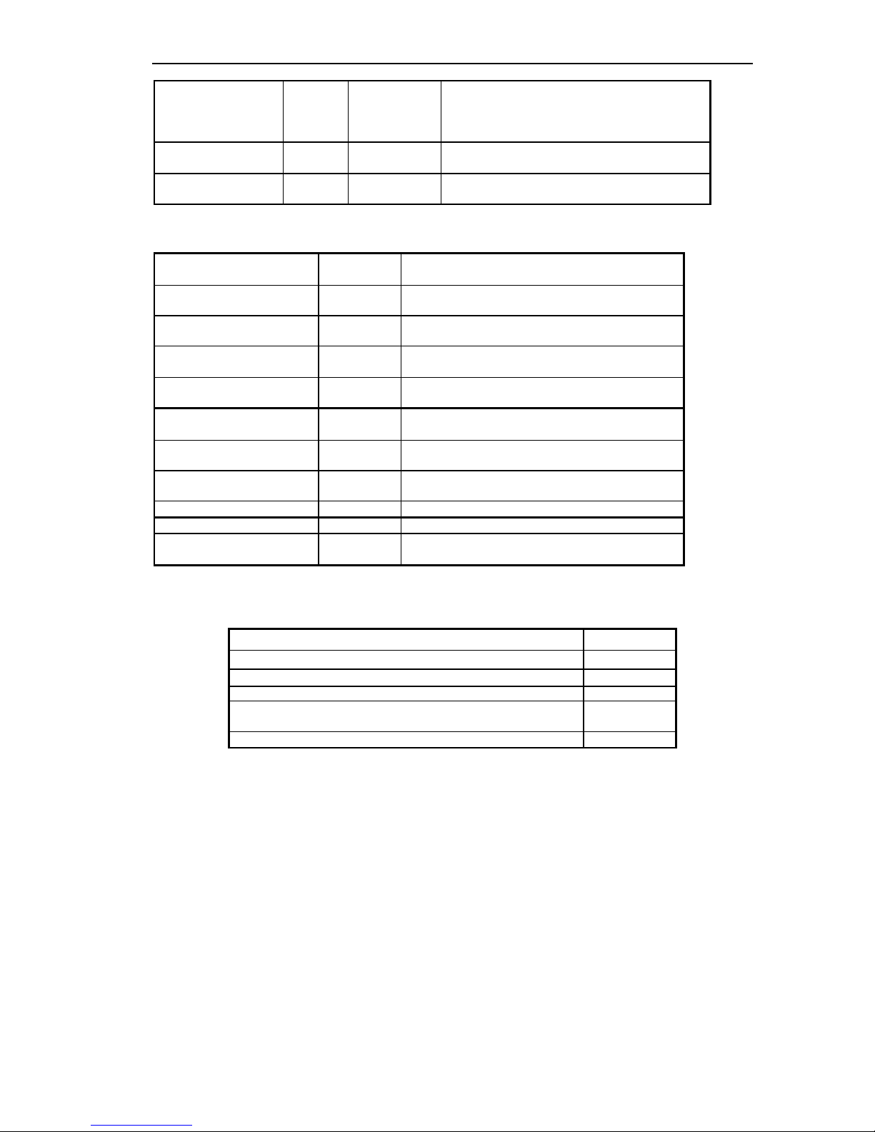
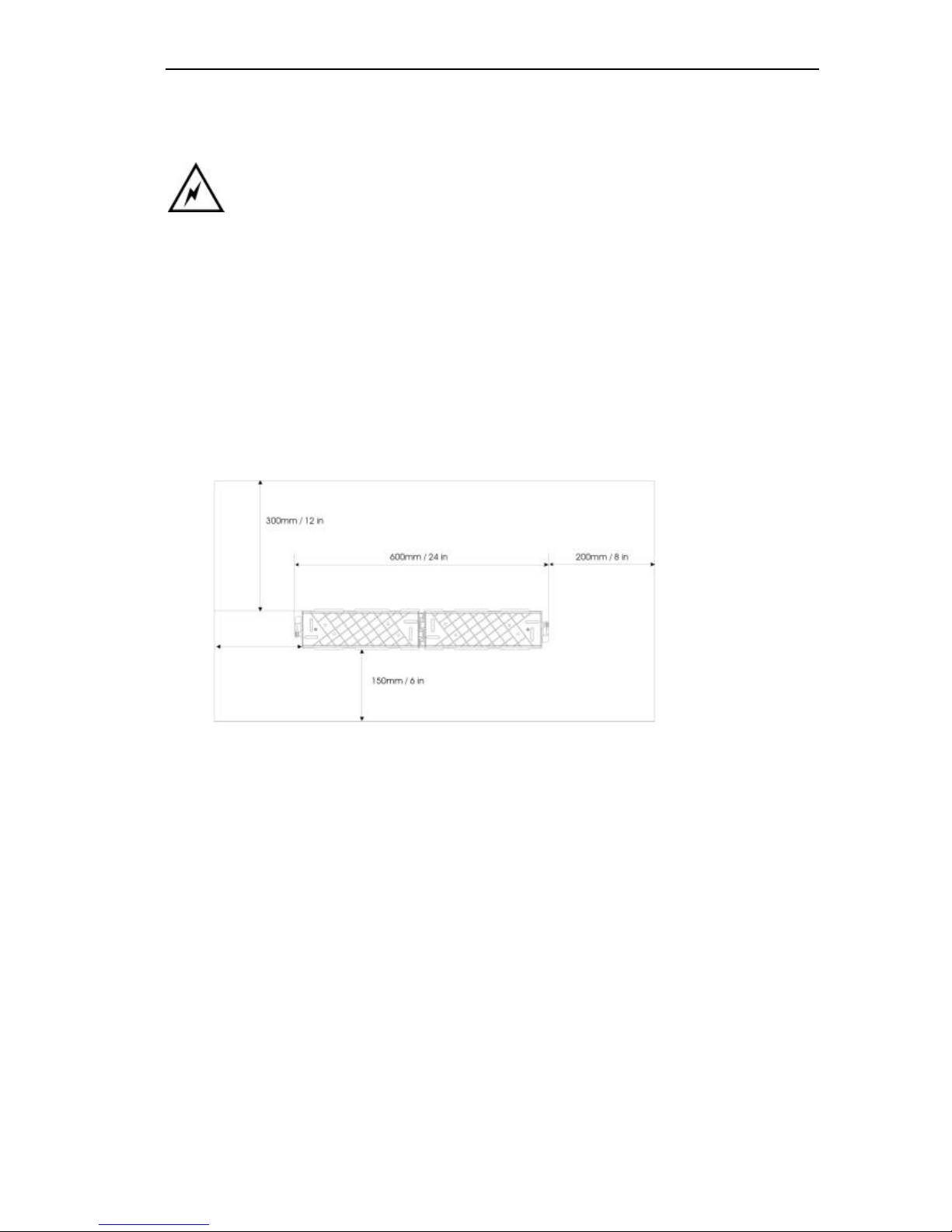
CCU Mounting bracket clearances
The main unit is mounted on a wall using the bracket supplied and should have top and side clearance as
shown below.
CCU Mounting Bracket
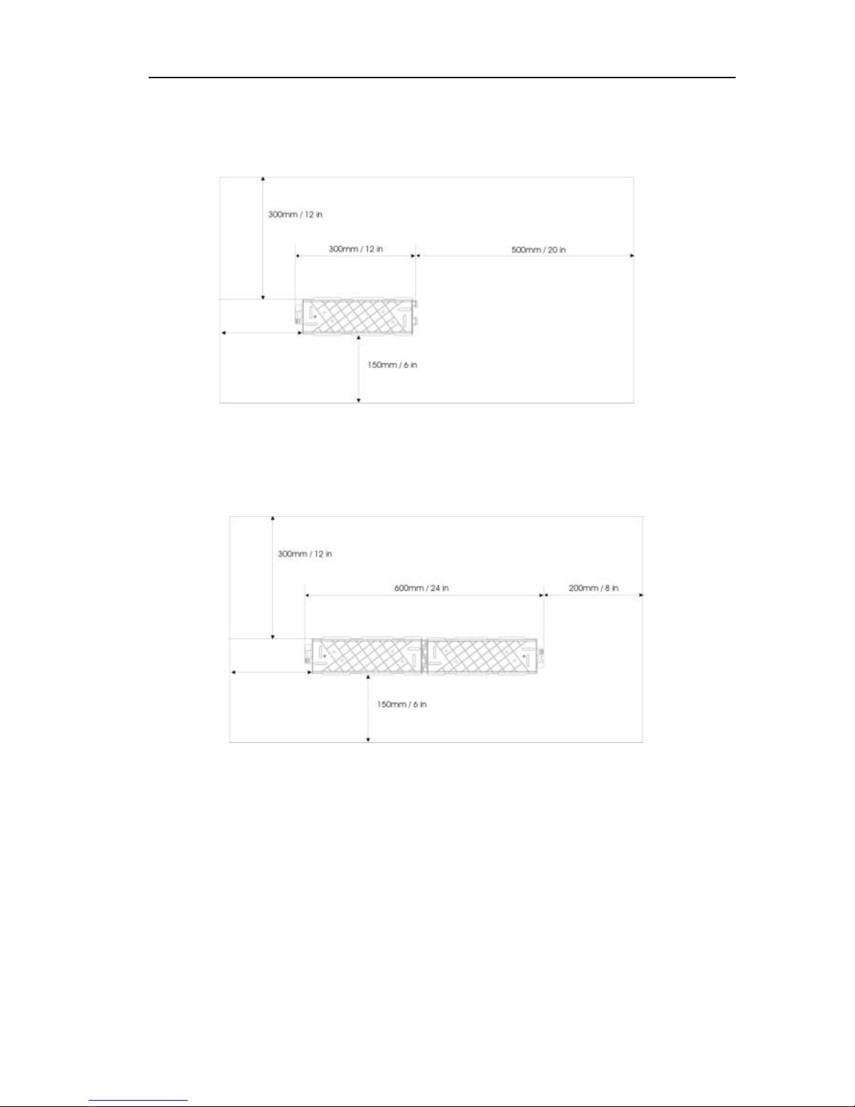
If the system is to be equipped with an Expansion or IP Router Module, then two mounting brackets need to
be installed.
CCU Bracket + Backplane Bracket
300mm min
Page 21
Inter-Tel EncoreCX
Installation & Maintenance Manual
20
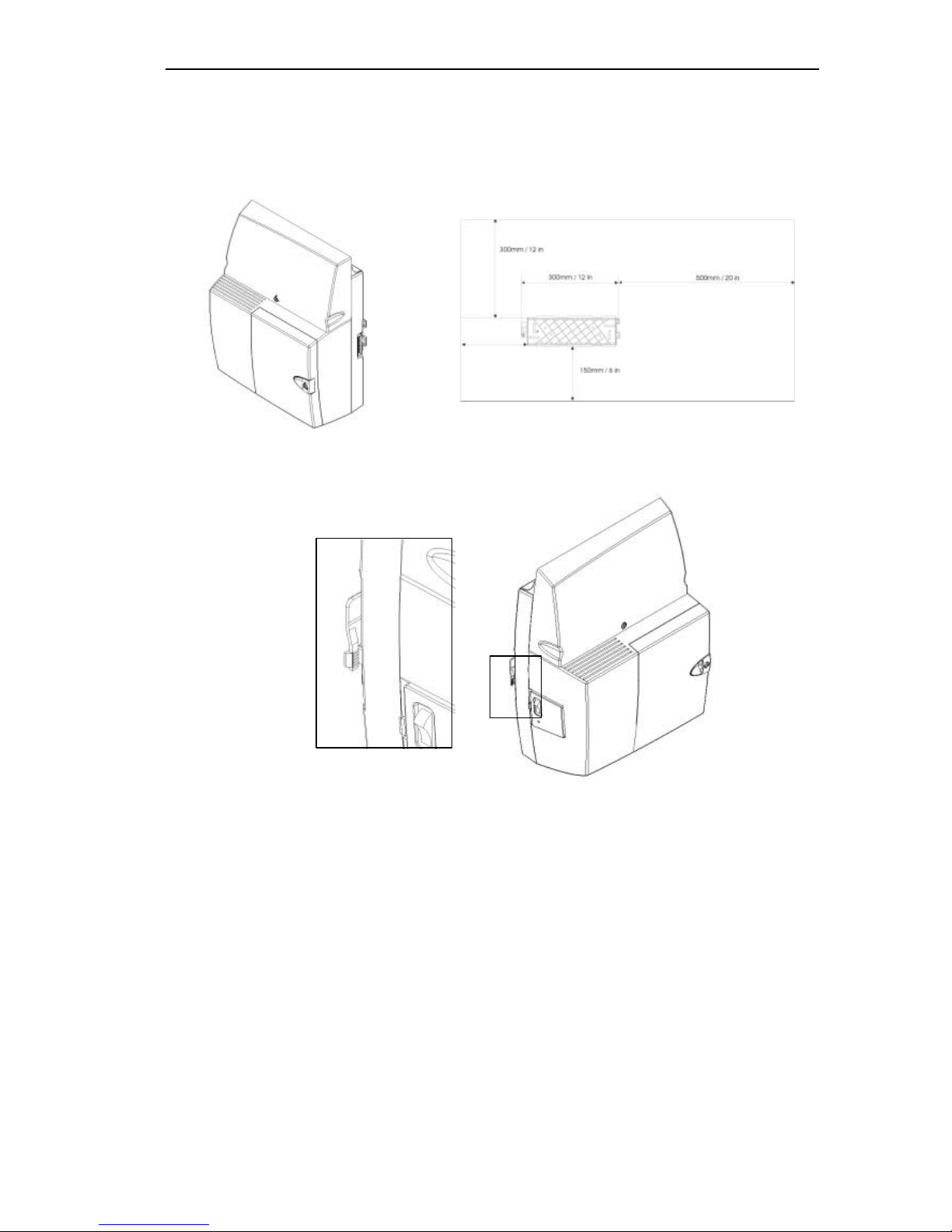
Mounting the CCU
The CCU is mounted on the bracket by sliding it on from the left-hand side. The marks on the side of the
CCU must be lined up with the flanges on the wall bracket as shown below before sliding the CCU into
place. When you slide it fully to the right-hand side of the bracket, the CCU is automatically locked in place.
To remove the CCU, depress the lock located on the left-hand side of the wall bracket. Slide the CCU to the
left to remove it from the bracket.
300mm min
Page 22
EncoreCX
Installation and Maintenance Manual
21
Modules located in the CCU
There are a number of modules that can be installed in the CCU.
• CO Line Module (Colored Black). This provides two CO lines. Up to two of these modules can be installed in
the CCU to provide two or four CO lines.
There are two slots in the CCU for the CO Line modules.
• Voice Module two, four or eight port (Colored Blue). Only one of these modules can be inserted in a unit.
• T1/PRI Module (Colored Yellow). This module provides for a T1/Primary Rate ISDN (PRI) interface.
When a T1/PRI Module is installed, the unit can be further equipped with one or two
CO line modules to p rovide backup in the event T1/ PRI Module fails.
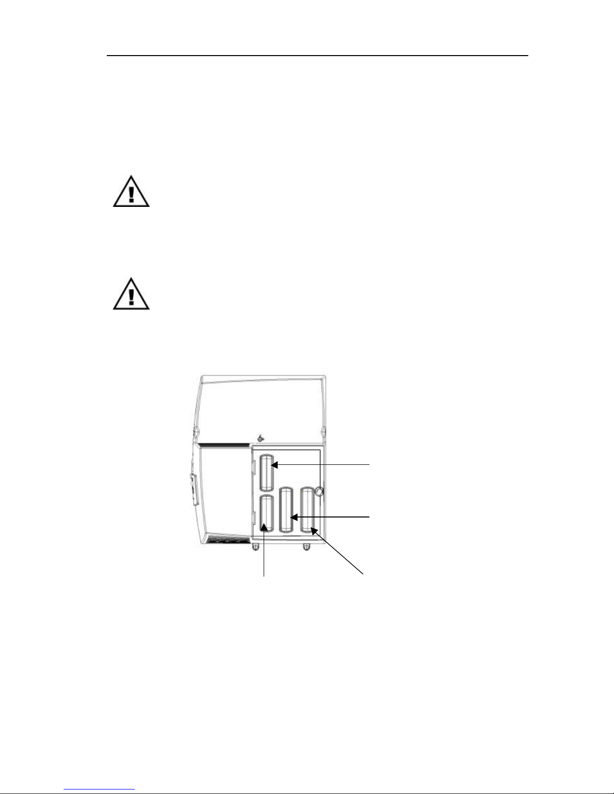
Module location
The CO line, Voice and T1/PRI Module locations in the CCU are indicated below.
CO Module 2
CO Lines 3 and 4
Voice Module
T1/PRI Module
CO Module 1
CO Lines 1 and 2
Page 23
Inter-Tel EncoreCX
Installation & Maintenance Manual
22
System Expansion
To equip the switch with more than eight extensions, two CO Line Modules or an IP Router Module, a
backplane, mounted on a second wall bracket, is needed.
The power must be disconnected to install the backplane or expansion modules.
Installing the Backplane wall bracket
The CCU and backplane brackets are identical. However, when both are installed, the backplane bracket is
inverted so that it meshes closely with the CCU bracket.
Locate the second bracket and mark the screw holes. Drill and plug the holes in the wall at the marked locations.
The holes should be deep enough to accept a one inch screw.
Mount the second bracket ensuring the two brackets are correctly interlocked and that sufficient clearance is
provided on all sides.
Mounting the CCU with two brackets
Slide the CCU on to the brackets from the left-hand side.
Ensure that the locking mechanism is activated.
Page 24
EncoreCX
Installation and Maintenance Manual
23
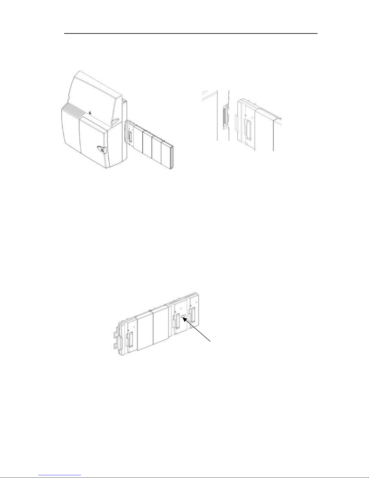
Mounting the Backplane
Slide the backplane on from the right-hand side.
Ensure the connector is fully mated wi th the CCU.
Securing the backplane to the wall bracket
A mounting screw is used to securely locate the backplane on the wall bracket. This provides additional rigidity
to ensure the backplane and CCU connectors do not move.
Remove the fourth and fifth cover from the backplane.
Locate the backplane on the bracket and connect it to the CCU.
The backplane must be fully connected to the CCU to correctly locate the mounting screw hole.
Insert the screw into the pillar on the bracket, which can be seen through the backplane mounting screw hole.
Mounting screw
hole
Page 25

Inter-Tel EncoreCX
Installation & Maintenance Manual
24
Expansion modules
There are two types of expansion modules that can be installed on the backplane. These are the Expansion
Module and the IP Router Module. These modules are installed in the same way.
The Expansion Module is also equipped with two connectors for the CO Line modules.
The power must be disconnected when installing the backplane or expansion
modules.
Expansion Module
Expansion Module separated
Upper Locking Screw
Lower Locking Screw
Page 26
EncoreCX
Installation and Maintenance Manual
25
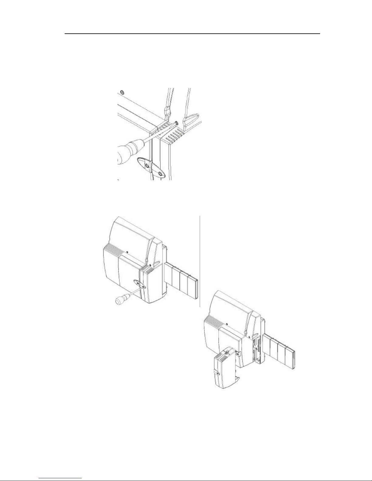
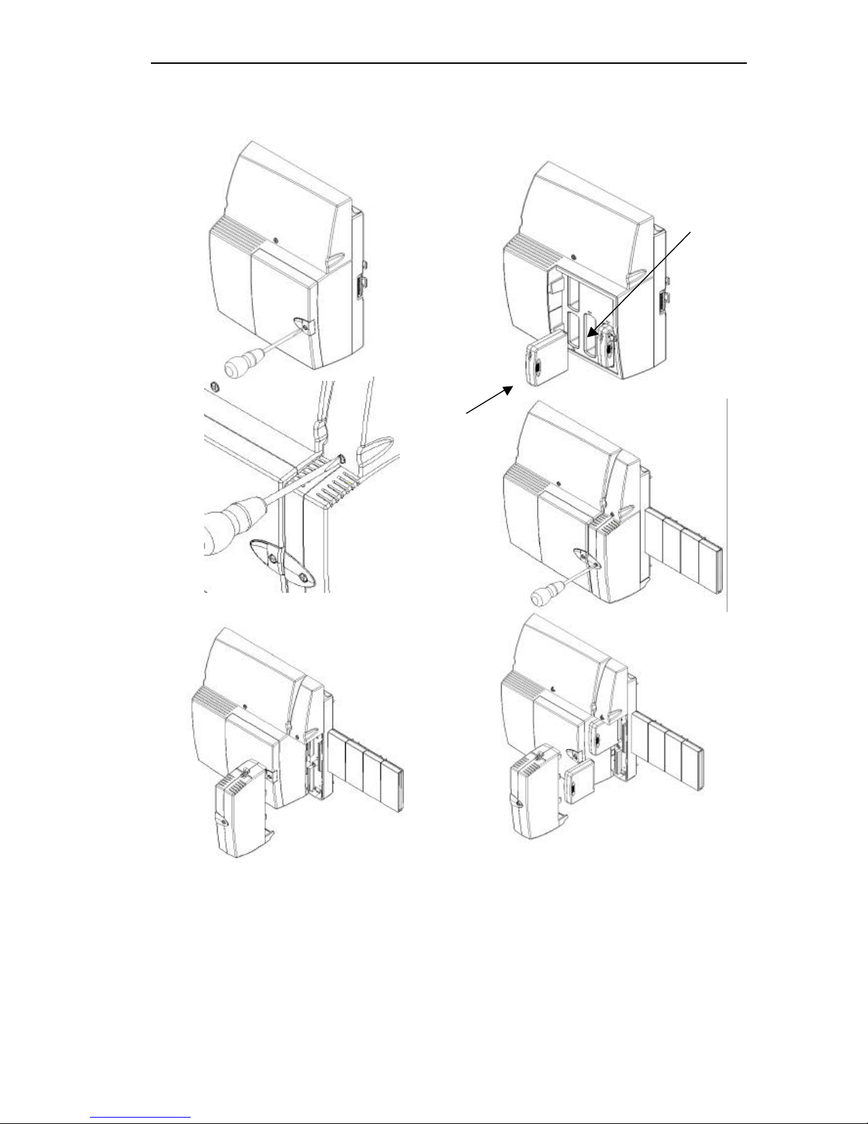
Removing the 008 module from the backplane
1. Unlock the upper locking screw by turning the locking screw, with a suitable screwdriver, ¼ turn
counterclockwise.
2. Lift the cover.
3. Unlock the Extension module locking screw by turning the locking screw, with a suitable screwdriver, ¼ turn
counterclockwise.
4. Gently pull the lower half of the module off.
Page 27
Inter-Tel EncoreCX
Installation & Maintenance Manual
26
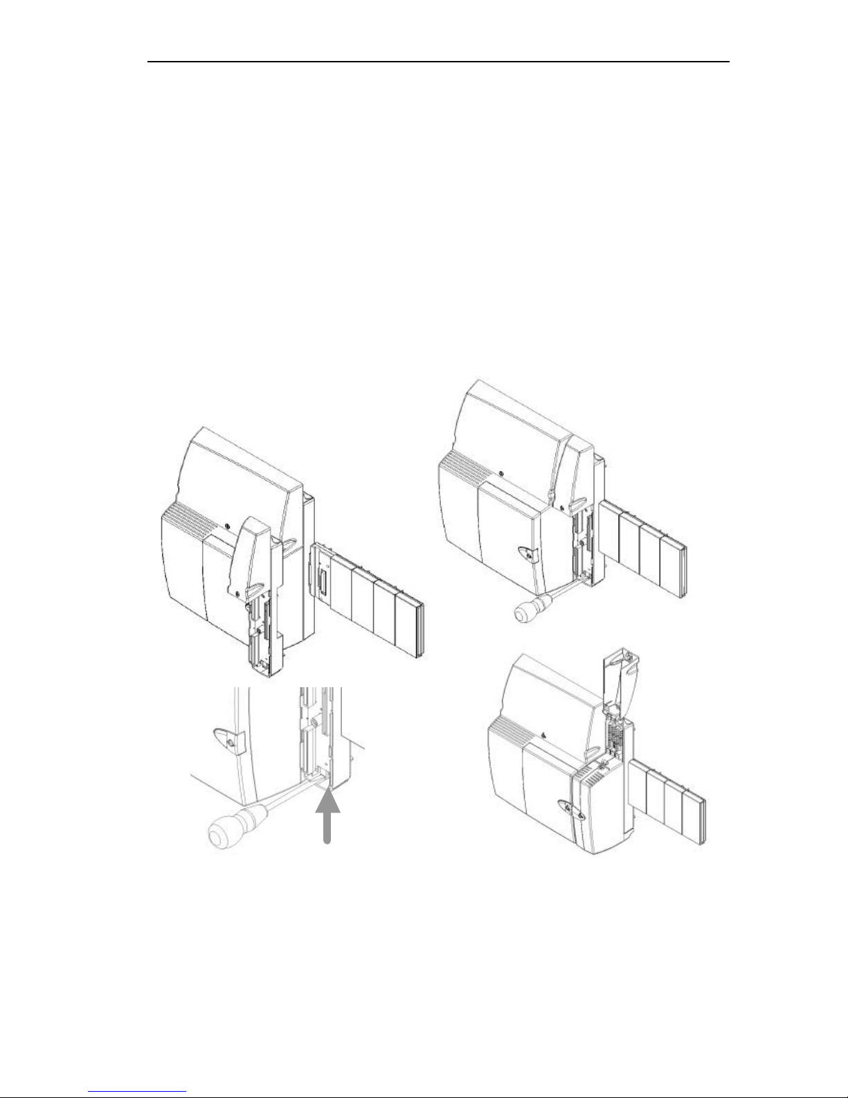
Installing the 008 module onto the backplane
1. Lift the MDF cover.
2. Align the connectors of the module and the MDF.
3. Gently push the 008 module onto the MDF.
4. Lock the 008 module in place by turning the locking screw ¼ turn clockwise with a suitable screwdriver.
Installing an expansion module
1. Install the backplane as described on page 22.
2. Install the MDF in the first free left-hand slot on the backplane.
3. Lock the MDF in place by pushing the lock bar upward using a screwdriver.
4. Lift the MDF cover and install the module.
Push up to lock
Page 28

EncoreCX
Installation and Maintenance Manual
27
CO Line Module
The CO Line module contains circuitry for two CO lines.
The module is colored BLACK and it can be installed in the CCU and also on the expansion module.
Note: There is an arrow on the module, which indicates the orientation of the card in the slot. The arrow always
points up.
Installing the CO module in the CCU
Remove the cover of the CCU.
Insert the CO Line Module in the CO Line Module slot or slots in the CCU.
The left-hand slot is the first module position.
Locating the CO Line mo dule in the Extension module
Remove the Expansion Module by firstly opening the Expansion MDF cover.
Open the Expansion Module and remove it from the MDF.
Insert the CO Line Module (or modules) on the MDF connectors.
The upper slot is the first module position.
CO Line Module
Page 29
Inter-Tel EncoreCX
Installation & Maintenance Manual
28
Locate the module
Remove the cover.
First CO Line
module position
Note: There is an arrow
located on the module to
indicate the orientation of
the card.
Page 30
EncoreCX
Installation and Maintenance Manual
29
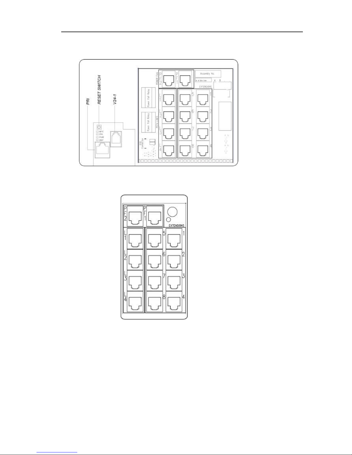
Termination in CCU
All extension and line cabling is terminated on the CCU with RJ11 connectors.
The T1 / PRI is terminated on an RJ45 connector.
Similarly, all line and extension cabl ing is terminated on the Expansion Modules with RJ11 connectors.
Page 31

Inter-Tel EncoreCX
Installation & Maintenance Manual
30
Voice Mail Module (Optional)
The Voice Mail module is colored BLUE.
It is positioned in the Voice Mail module slot in the CCU.
There are thr ee versions, two-port with five hours capacity, four-port with 10 hours capacity and eight-port with
20 hours capacity.
A label identifies the different modules. The label location is indicated in the drawing below.
V oice Module
identification label
Page 32

EncoreCX
Installation and Maintenance Manual
31
External Music -on-Hold Module
The external Music-On-Hold Module is supplied with a stereo jack for the input from the external source and a
cable to connect to an extension position. The extension that is to be used as the external Music-On-Hold source
is selected in System Programming. See Page 81.
It is recommended that one of the extensions in the CCU be used. The module is stuck to the unit, or wall if
equipped externally, with double -sided tape supplied.
T1/PRI Module
The T1/PRI Module is colored Yellow.
It is located in the T1/PRI slot in the CCU.
Page 33

Inter-Tel EncoreCX
Installation & Maintenance Manual
32
Connecting the Battery-Backup-Unit (BBU) to the system
The battery back up provides full operati on of the system for approximately one hour in the event of a power
failure. The battery will support 11 erlangs of voice traffic for 1 hour.
An erlang is a measure of telephony traffic. 1 erlang = 1 circuit fully occupied for 1 hour
The battery back up consists of the 12V battery and the charger unit.
Before installing the battery charger unit, ensure that the system is powered
down by disconnecting the main AC power source.
To install the unit, remove the blanking cover on the left side of the CCU.
• Open the CCU MDF cover by releasing the MDF locking screw.
• Slide the BBU in about half way.
• There are three cables connected to the charger unit. One with a connector, which connects to the PSU,
and two with spade connectors that are connected to the battery.
• Connect the cable with the connector to the PSU (Power Supply Unit).
• Thread the two cables for the battery up the cable guide to the battery compartment.
• Push the charger unit home.
• Replace the CCU cover.
Battery charger connector
on the PSU
Battery Cable Guide
Page 34

EncoreCX
Installation and Maintenance Manual
33
Connecting the battery
Ensure the battery switch on the BBU unit is turned off. This switch does not
turn off the main supply. The main AC power source is disconnected by
unplugging the main cord.
1. Insert the battery into the battery cavity in the CCU.
2. Connect the cables from the battery charger to the battery ensuring that the cables are connected correctly.
Red cable to red battery terminal, black cable to black battery terminal.
3. Reconnect the main AC power source.
4. Turn the battery charger switch on.
Light Emitting Diode (LED) Indicators
A status LED on the BBU is provided.
• GREEN indicates the unit is running from main AC power source and the battery is charging or
fully charged.
• ORANGE indicates the unit is running off the battery.
• RED indicates that the battery is discharged.
• Flashing RED indicates the battery is disconnected and the switch is running from the main.
Status LED
Page 35

Inter-Tel EncoreCX
Installation & Maintenance Manual
34
Extensions
ECX 2000 digital telephone set
ECX 2000 connections (underside of phone)
All ECX 2000 digital telephone sets are supplied with a 5V DC Power transformer.
Handset connector
Line cord connector
DC Adapter connector
Data Port
Headset Port
DSS socket
Page 36

EncoreCX
Installation and Maintenance Manual
35
ECX 1000/ ECX 1000W digital telephone
ECX 1000/ ECX 1000W digital telephone connections (underside of phone)
Headset Port
Data Port
Handset connector
Line cord connector
Test port only. No user functionality
Page 37

Inter-Tel EncoreCX
Installation & Maintenance Manual
36
Attaching the digital telephone desk pedestal (ECX 1000/ECX 1000W and ECX 2000)
Position at 35 degrees Position at 20 degrees
Wall mount Plinth position
Pedestal position 20 °
Pedestal position 35°
Test port only. No user functionality
Page 38

EncoreCX
Installation and Maintenance Manual
37
Direct Station Selection (DSS) unit
The ECX 2000 digital telephone set can be equipped with a 32 -key DSS. This provides 32 additional
programmable keys.
Up to eight ECX 2000 digital telephones can be equipped with a DSS. From the system programming menus,
you program which extensions are equipped with this module.
To connect the DSS unit to an ECX 2000 digital telephone (ECX 2000 only)
Use the six-inch cord to connect the DSS to the base of the ECX 2000 digital telephone. The DSS connector is
marked on the base of the telephone.
Additional power must be supplied to the telephone. This is done by connecting the 5V power supply to the DC
jack on the base of the telephone.
Page 39

Inter-Tel EncoreCX
Installation & Maintenance Manual
38
Clip, Pedestal and installation of the DSS
NOTE: For the 20 degrees position or the 35 degrees position, refer to page 35.
6" cord (RJ11
connector)
Cord Rail
Page 40

EncoreCX
Installation and Maintenance Manual
39
Wall-mounting an ECX 1000 or ECX 2000 telephone
The phone pedestal is inverted on the base to wall mount the phone.
Locate, drill and plug the two screw locations as shown below. The holes should be deep enough to accept a oneinch screw. Insert the two screws leaving sufficient space to clip the base over them. Locate the phone and base
over the screws.
6 inches
Line cord rails
ECX 2000 and DSS in
Wall-Mount position
Digital telephone
set in Wall-Mount
position
Page 41

Inter-Tel EncoreCX
Installation & Maintenance Manual
40
Door Phone
The door extension is connected to extension 23, the fourth extension on the CCU.
Mounting
screw
Door Phone
bracket
Connect the single pair from the door extension to the AB connections on extension 23.
The system must be programmed to recognize the Door Phone. Refer to the Administrator's Manual for
programming details.
Wall hook when the ECX
1000/ECX 2000 is in a 20
degrees or 35 degrees position
Wall hook when the ECX
1000/ECX 2000 is wall mounted
Page 42

EncoreCX
Installation and Maintenance Manual
41
V-2904 Valcom Answering System Installation
Installation
1. Following the industry standard, install a 25 pair cable with female amphenol to the V -2904. Terminate the
other end on an M-66 Block.
2. Connect the power supply (VP-624) to Violet/Slate (note: Slate is gray) pairs on the M-66 Block.
Power Supply 66 Block
-24 Volts S/V (Slate/Violet Pair)
+24 Volts V/S (Violet/Slate Pair)
Note: The Power LED located on the V-2904 board should illuminate if properly connected.
3. Install an RJ11 jack near the EncoreCX equipment with connection back to the M-66 Block for Tip and Ring
connection.
Jack 66 Block
Tip W/BL (White/Blue)
Ring BL/W (Blue/White)
4. Connect a conductor line cord (minimum two conductors) from the jack to an unused CO trunk port on the
EncoreCX.
5. Run a cable (minimum four conductors) from the M-66 Block to the door speakers.
Page 43

Inter-Tel EncoreCX
Installation & Maintenance Manual
42
Below is the listing for connecting each four -pair cable using the white/blue and white/orange pairs from door
speake rs to an M-66 Block.
Speaker 1 4-Pair Cable M-66 Block
1(Speaker Tip) White/Blue R/O (Red/Orange)
2 (Speaker Ring) Blue/White O/R (Orange/Red)
3 (Call Button) White/Orange R/G (Red/Green)
4 (Call Button) Orange/White BL/R (Blue/Red)
Speaker 2 4-Pair Cable M-66 Block
1(Speaker Tip) White/Blue BK/O (Black/Orange)
2 (Speaker Ring) Blue/White O/BK (Orange/Black)
3 (Call Button) White/Orange BK/G (Black/Green)
4 (Call Button) Orange/White BL/BK (Blue/Black)
Speaker 3 4-Pair Cable M-66 Block
1(Speaker Tip) White/Blue Y/O (Yellow/Orange)
2 (Speaker Ring) Blue/White O/Y (Orange/Yellow)
3 (Call Button) White/Orange Y/G (Yellow/Green)
4 (Call Button) Orange/White BL/Y (Blue/Yellow)
Speaker 4 4-Pair Cable M-66 Block
1(Speaker Tip) White/Blue V/O (Violet/Orange)
2 (Speaker Ring) Blue/White O/V (Orange/Violet)
3 (Call Button) White/Orange V/G (Violet/Green)
4 (Call Button) Orange/White BL/V (Blue/Violet)
Cable Pair Pin
Numbe
r
Connections Cable Pair Pin
Numbe
r
Connections Cable Pair Pin
Numbe
r
Connections
White/Blue 26 Brown/Red 9 Green/Yello
w
18
Blue/White 1
Tip and Ring
Red/Slate 35 Yellow/Brown 44
White/Orange 27 Slate/Red 10 Brown/Yellow 19
Orange/Whit
e
2 Black/Blue 36 Yellow/Slate 45
White/Green 28 Blue/Black 11 Slate/Yellow 20
Green/White 3 Black/Orange 37 Violet/Blue 46
White/Brown 29 Orange/Black 12 Blue/Violet 21
Brown/White 4 Black/Green 38
DOOR BOX
2
Violet/Orange 47
White/Slate 30 Green/Black 13 Orange/Violet 22
Slate/White 5 Black/Brown 39 Violet/Green 48
DOOR BOX
4
Red/Blue 31 Brown/Black 14 Green/Violet 23
Blue/Red 6 Black/Slate 40 Violet/Brown 49
Red/Orange 32 Slate/Black 15 Brown/Violet 24
Orange/Red 7 Yellow/Blue 41 Violet/Slate 50
Red/Green 33
DOOR BOX 1
Blue/Yellow 16 Slate/Violet 25
Power
Supply GRD
-24 VDC
Green/Red 8 Yellow/Oran
ge
42
Red/Brown 34
Orange/Yellow 17
Yellow/Green 43
DOOR BOX
3
Page 44

EncoreCX
Installation and Maintenance Manual
43
Programming
The V-290 will provide ba sic functions as default settings. Depending on customer requirements, the
volume may be the only adjustment required.
Refer to pages 8, 9 and 10 of the V-2904 Installation Guide for volume adjustments and programming
information.
Operation
Up to four door phone stations may be installed.
When the door phone button at a station is pressed, the V-290 initiates ring-in on the EncoreCX line
and sends a confirmation tone to the door.
When the EncoreCX phone is answered, a series of optional tones may be heard in the receiver. These
tones numerically indicate which door is calling.
Example: Station 1 – Beep
Station 2 – Beep-Beep
When the phone is busy with one station and a call is placed from another station, the person on the
telephone will hear a call waiting tone corresponding to the door location.
Note: This station identification is available as a default, but can be disabled during programming if
required.
If the door is equipped with an electric strike plate, a code can be dialed from the phone to operate the
relay and unlock the door.
Note: The default code is * for all door phones, but can be changed during programming (refer to page
9 of the V-2904 Installation Guide).
Refer to page 10 & 11 of the V-2904 Installation Guide for additional operational information.
Page 45

Inter-Tel EncoreCX
Installation & Maintenance Manual
44
Cabling the unit
All the extensions and lines are connected to the switch by RJ11 connectors located in the MDF areas.
RJ11 connectors or optional patch panel with RJ11 type connections should be mounted or placed less than 7' of
the CCU to facilitate using standard modular cables of 7' in length.
External lines should be connected via RJ11 from the CCU to the telecommunications interface. It is
recommended the telecommunications provider terminate the lines with RJ11 interfaces. In the event the lines are
terminated with another interface, such as RJ21, the installer may install their own RJ11 connections from the
RJ21.
Caution
Use only 26AWG line cord or larger for CO line connections.
Cabling Breakouts
Page 46

EncoreCX
Installation and Maintenance Manual
45
Connecting the extensions
It is recommended that all extensions be cabled with two pairs. The ECX 1000 series telephones and ECX 2000
digital telephones use all four wires and standard phones use the AB pair only.
Do not exceed the following resistance or distance limits when connecting extensions to the System Unit. (The
distances listed assume 24 AWG tinned copper conductor is used.)
• 100 Ohms, or 1600 feet, for digital telephone sets
• 400 Ohms, or 6500 feet, for a standard telephone
The extension cables must be of twisted-pair construction, using 24 AWG wire.
All extensions should connect into standard line jack units. Extension cabling
should not be exposed to high voltage surges, (for example, surges induced by
lightning or neighboring high current-carrying cables). If this is a possibility,
external protection of the CCU and extensions using earthed line surge
protectors is essential.
Connector pinout Function RJ11 pinout
A Speech Pin 3
B Speech Pin 4
C Data Pin 2
D Data Pin 5
Connecting T1 / PRI Trunks
T1 / PRI trunks are terminated in the CCU MDF using an RJ 45 connector.
For T1/PRI trunks terminated on RJ48C jacks near the MDF, use a four -pair, non-reversing, mod-to-mod line
cord to connect the T1 to the CCU.
Page 47

Inter-Tel EncoreCX
Installation & Maintenance Manual
46
For T1/PRI trunks terminated on RJ48C jacks away from the CCU, you will need two eight-conductor modular
jacks and two four -pair, non-reversing, mod-to-mod line cords. Run enough cable to extend from the telco RJ48C
jack to the CCU.
For T1/PRI trunks terminated on an RJ-type block, use an eight-conductor modular jack assembly and a fourpair, non-reversing, mod-to-mod line cord. Run enough cable to extend from each telco termination to the CCU.
Page 48

EncoreCX
Installation and Maintenance Manual
47
Structured Wiring
For technicians who are implementing standards-based, structured wiring in commercial or residential
applications the following applies: -
Commercial Installation
§ You will not have to change your base wiring if you are using Cat 5e or Cat 6 cable and implementing a 568
standard installation where the cable from the faceplate jack terminates in the closet to a patch panel.
§ It does not matter if you have used the 568A or 568B wiring scheme on the jacks and patch panels as long as
you have done the same wiring on each end of the cable.
§ Use the RJ12 (4-wire) patch cables (also referred to as four wire silver satin line cords) to connect from the
CCU or Ports Module.
§ The supplied cable from the ECX 100, ECX 1000 and ECX 2000 phone will plug into the 8-pin, 8-wire jack
(RJ45) you have installed in the faceplate. However, Inter -Tel does not recommend connecting the supplied
ECX phone cable to a RJ45 jack. This could cause intermittent problems with the phones.
§ Install your structured wiring according to the 568 standards and patch the jacks you want to designate as
“phone” to the phone system.
§ Patch the jacks you want for data to the data switch (data patch cables will require 4-pair cables and 8-pin
plugs).
Residential Installation
§ You will not need to change any of the structured wiring for the residence if you are installing Cat 5e (or Cat
6) and implementing a 570 standard installation.
§ In the 570 standard, you will wire from the faceplate jack with Cat 5e cable.
§ The cable will be terminated at the faceplate jack with the 568A wiring scheme.
§ The cables within your structured wiring box will be terminated to the 8-pin jack module in your wiring box.
(Note: Some residential systems terminate to a modular plug, which is not in compliance with 570 standards.
If your system does this, you will need to supply modular Female-to-Female couplers).
§ From your CCU or Ports Module you will patch the cables identified as tel ephone with a RJ12 patch cable,
(also referred to as four wire silver satin line cords).
§ You will need to utilize the system manufacturer’s adapter to plug into the demarc extension jack so you
have four separate jacks for CO lines.
§ You will need one patch cable RJ11 (2-wire) or RJ12 (4 -wire) to connect the telephone (CO) lines to the
CCU or Ports Module.
§ The connection between the CO is done via a 2-wire connection, but will work with a 4-wire (RJ12) patch
cable.
Page 49

Inter-Tel EncoreCX
Installation & Maintenance Manual
48
CCU connections
The CCU has the following connectors:
• Eight RJ11 connectors for the extensions.
• Four RJ11 connectors for the CO lines.
• An RJ45 for the T1/PRI.
• One RJ11 connector for serial interface RS232.
• A two-position screw terminal for a doorstrike connection, labeled as ”DS”.
• An Electrostatic Precaution (ESP) connector.
A reset switch is provided which provides a software reset.
DOORSTRIKE
Door Phone
The Door Phone is cabled to extension 23, the fourth extension on the CCU. To operate the Door Phone, it must
be programmed in system programming. See Page 84.
Doorstrike
The Doorstrike port provides a closed relay contact when in the operated condi tion. The relay contact is designed
for low voltage DC equipment and should not be used for any voltages greater than those specified within the
technical specification.
Connecting a PA (Public Address) amplifier
Any of the extensions on the system, with the exception of the programming extension, can be programmed as a
PA position. The PA is connected to the AB pair of the extension. See programming on Page 84.
Inter-Tel EncoreCX can work with two types of paging amplifiers on a station port; those designed to work on
telephone systems, and those which only offer a microphone input.
If the PA Amplifier is one designed to work on telephone systems then the extension port can be directly
connected to the PA amplifier. On the amplifier, typically, the input is marked "telephone" and has the internal
600 ohm transformer isolated input built in.
Page 50

EncoreCX
Installation and Maintenance Manual
49
If the paging amplifier is the type that provides a microphone input a 1:1 Audio Isolation transformer with a 600
to 900 ohm impedance must be connected between the extension port and the microphone input. A Radio Shack
1:1 Audio Isolation Transformer (p/n 273-1374) was used by Inter -Tel to verify this operation, but any
transformer with a similar specification wil l work. In addition, commercial 1:1 (600 - 600 ohm) transformers are
available from most sound system suppliers.
Connecting a PC or Printer to the Serial Port
A six-foot cord with a four-way RJ11 plug on one end and a six-way RJ plug on the other is provided. An RJ-toDB9 adapter is also provided.
Connect the cord to the four -way RJ11 connector on the CCU.
Connect to the PC using either the six-way RJ plug or the cord and DB9 converter as required.
The pinouts from the RS 232 interface of the DB9 to the RJ11 are:
DB9 connector RJ11 plug
2 4
3 3
5 1
Central Bell
If a central bell is required, connect it to a spare extension position and include the extension in the Ringing
Groups that require the bell.
Extension Module MDF Connections
The connections on the Extension module are shown below.
• Eight RJ11 connectors for the extensions.
• Four RJ11 connectors for the CO lines.
• Two RJ11 power failure connectors.
Page 51

Inter-Tel EncoreCX
Installation & Maintenance Manual
50
IP Router Module connections
The IP Router has a built in ADSL modem.
To connect to an ADSL line use the gray lead provided to connect between the ADSL connector on the MDF
and the data port on the splitter.
If connecting to a cable modem or a managed IP network use the blue cable to connect between the 10/100 Base T WAN connector and the external router / modem.
There are six indicators (LEDs) on the MDF cover.
• Heartbeat – flashes to indicate normal processor activity
• ADSL - a solid light indicates ADSL line synchronisation
• LAN 1 - a solid light indicates an Ethernet connection
• LAN 2 - a solid light indicates an Ethernet connection
• LAN 3 - a solid light indicates an Ethernet connection
• LAN 4 - a solid light indicates an Ethernet connection
• There is an additional indicator inside on the MDF. This is the WAN indicator - a solid light indicates an
Ethernet connection
Page 52

EncoreCX
Installation and Maintenance Manual
51
Expanding an existing system
Modules may be removed and re-inserted in a system without disconnecting the power. See page 59.
However, if additional modules are being installed in a working system, it is necessary to power the system down
before installing a module or backplane.
If additional CO Line modules are to be installed in spare slots, the system needs to be reset before the switch
recognizes the new modules.
Installing an additional CO Line Module
CO line modules can be installed in spare slots on the system without powering the system down. However the
module will not be activated until the system is reset. This can be achieved by pressing the reset button on the
CCU.
Pressing the reset button will invoke a software reset and clear any calls in
progress.
Installing additional Extension Modules or an IP Router Module
The system must be powered down before installing an additional module on the backplane. It is recommended
that the module, and any additional CO line modules that may be required, be installed before the system is
powered up. When the system is powered up, the additional modules will be recognized by the system.
The power must be disconnected before installing an Extension or IP Router
Module or backplane. If battery back -up is provided, ensure the BBU switch is
off and the main AC power source is disconnected.
Page 53

Inter-Tel EncoreCX
Installation & Maintenance Manual
52
T1 / PRI on the EncoreCX
The EncoreCX can be equipped with a T1/PRI Module providing a T1 Robbed Bit Signaling (RBS) or PRI
(ISDN) interface.
When the module is installed and the system is powered up the module is detected.
NOTE: If the module is installed while the system is powered up the switch must be reset before the module is
detected.
The default setting is that the module is programmed as a T1 (RBS) circuit with 24 channels. All channels are set
as type E&M, wink start. None of the services described below are set.
It is recommended that the programming of the T1/PRI be carried out through the MPS. This is recommended
purely because the programming can be complex and it is easier to do through the MPS.
TI (RBS) Settings
A number of settings are programmable for each individual channel. The programming of these options must
match the line and service type supplied by the Telephone Company on each channel.
When a T1 / PRI module is programmed as a T1 (RBS) channels can be programmed as E&M, DID, Loop Start
or Ground Start. See page 111 for the programming from the programming telephone.
E&M Type
The E&M type provides two way calling.
A number of start types, Wink, Immediate, Delay Dial and Dial Tone are available.
The setting should be selected to match the type supplied by the Telephone Company. Programming of the start
types from the programming position is explained on page 112.
The service types AN I, DNIS, *ANI*, *DNIS* and *ANI*DNIS* are available. Again the programming of the
service type should match the service provided by the Telephone Company. The default is that no service type is
set. The programming is described on page 111.
DID TYPE
This is an E&M circuit that provides incoming calls only. The start types available on DID lines are Wink,
Immediate and Delay Dial.
The setting should be selected to match the type supplied by the Telephone Company. For programming from the
programming position see page 112.
The service types ANI, DNIS, *ANI*, *DNIS* and *ANI*DNIS* are available. Again the programming of the
service type should match the service provided by the Telephone Company. The default is that no service type is
set. The programming is described on page 111.
Loop Start Type
This type provides two way calling.
The only service available is Caller ID provided using modem tones (FSK). The programming for Caller ID
Detection is shown on page 111. The default is that Caller ID is not programmed.
NOTE: If Caller ID is programmed ON and the service is not available on the lines, the switch will attempt to
detect the Caller ID on all incoming calls. It will only route the call and start ringing phones when it has failed to
detect the Caller ID. This will delay the ringing by a number of seconds. The Line led will appear red while the
switch tries to detect the Caller ID and will change to green when the call starts to ring the telephone. It is highly
recommended that the Caller ID be turned off when no Caller ID is provided on the lines so that calls are dealt
with more efficiently.
Ground Start Type
This type provides two way calling.
There are no services programmable for Ground Start Lines
Page 54

EncoreCX
Installation and Maintenance Manual
53
Framing and Coding on T1 (RBS)
The framing and Coding applies to all the channels on the T1. The options in Framing are D4 superframe (JB7)
or Extended Superframe (ESF). See page 110. The Coding options are AMI (Alternate Mark Inversion) or B8ZS
(Bipolar with 8 Zero Substitution). See page110. The default settings are D4 and AMI.
Changes to the Framing or Coding only take effect when the switch is reset. If you go on hook at
the programming position after changing the settings, the switch will automatically reset. You
can also reset th e switch by pressing the reset button.
Line Build Out
The Line build out applies all the channels on the T1 and can be set at 0 dB, -7.5 dB, -15 dB and -22.5 dB. The
default setting is -7.5 dB. The setting depends on how far it is to the first repeater on the span. The programming
is described on page 111.
Changes to the Line Build Out only take effect when the switch is reset. If you go on hook at the
programming position after changing the setting, the switch will automatically reset. You can
also reset the switch by pressing the reset button.
Line Gain
The Line Gain can be adjusted for each channel. If calls on a particular channel or channels are giving an echo
then the gain sho uld be adjusted down to reduce it. There are three settings provided, low (-9 dB), medium
(-6dB) and high (-3dB). The default setting is high. See the programming on page 113.
Low is the recommended receive setting as specified in EIA 464C. Medium is the recommended value in EIA
464B.
DTMF or Pulse dialing
Each T1 channel can be set to be either DTMF or Pulse dialing. The default is that DTMF dialing is set. See the
programming on page 113.
Received Digits
On T1 channels programmed with ANI or DNIS the switch does not know how many digits it is likely to receive.
In order to speed up the call processing the number of digits that will be received is programmed. It is set at 2 in
default. See page 113.
If *ANI* or *DNIS* is available then the programming is ignores as the *s indicate the beginning and end of the
digit stream.
Programming the number of channels on a T1 span
The programming of the number of T1 channels available on the switch is programmed in the Equipped Lines
programming. See page 101. The T1 circuits are shown as Lines 1 - 24. The switch can also be equipped with up
to 4 CO Lines. These are always numbered Lines 25 -28.
Page 55

Inter-Tel EncoreCX
Installation & Maintenance Manual
54
Programming required for PRI (ISDN)
The default programming of the T1/PRI module is that it is set as T1 (RBS). The programming must be changed
to provide a PRI circuit. This programming is described on page 110.
Changing from T1 (RBS) to PRI (ISDN) and vice versa only takes effect when the switch is
reset. If you go on hook at the programming position after changing the setting, the switch will
automatically reset. You can also reset the switch by pressing the reset button.
Programming the Q 931 protocol on PRI (ISDN)
Two ISDN protocols are provided in the switch, National ISDN 2 and 5ESS.
The default setting is National ISDN 2. The programming is described on page 115.
Recommended PRI ISDN Protocol settings:
EXCHANGE EQUIPMENT (TELCO)
TRANSLATION PROTOCOL
ENCORECX ISDN Q931 Protocol
AT&T 5ESS (AT&T Custom) AT&T 5ESS (Custom)
AT&T 4ESS (AT&T Custom) AT&T 5ESS (Custom)
NORTEL CUSTOM (DMS Exchanges) See note NATIONAL ISDN 2
NATIONAL ISDN 1 (DMS Exchanges) See note NATIONAL ISDN 2
NATIONAL ISDN 2 NATIONAL ISDN 2
NOTE: The DMS Exchange equipment or DMS Central Office (ONLY) must have the LT1 flag under the trunk
sub group programmed to YES to avoid issues. See page 58 for a fuller description of the LT1 issues.
Changing the Q931 protocol only takes effect when the switch is reset. If you go on hook at the
programming position after changing the setting, the switch will automatically reset. You can
also reset the switch by pressing the reset button.
Line Build Out programming on PRI (ISDN)
The Line build can be set at 0 dB, -7.5 dB, -15 dB and -22.5 dB. The default setting is -7.5 dB. The setting
depends on how far it is to the first repeater on the span. The programming is described on page 114.
Changes to the Line Build Out only take effect when the switch is reset. If you go on hook at the
programming position after changing the setting, the switch will automatically reset. You can
also reset the switch by pressing the reset button.
Line Gain programming for PRI (ISDN)
The Line Gain can be adjusted for the full PRI; it changes the gain for all channels. If calls are giving an echo
then the gain should be adjusted down to reduce it. There are three settings provided, low (-9 dB), medium ( 6dB) and high (-3dB). The default setting is high. See the programming on page 114.
Low is the recommended receive setting as specified in EIA 464C. Medium is the recommended value in EIA
464B.
Additional programming options for PRI (ISDN)
There are two additional programming options which can be set when the T1/PRI module is programmed as PRI.
These are presented under the PRI programming option in the Line programming menu.
Page 56

EncoreCX
Installation and Maintenance Manual
55
Accept on Busy
The option is provided on PRI (ISDN) to accept or reject calls. When the default setting Accept On Busy is set
then calls will be presented to busy extensions. The extensions will be presented with a call waiting indication. If
the user prefers that callers directed to individual extensions (using DID or routing on Caller ID) will receive
busy tone when the extension is busy then the Reject on Busy setting should be set. See the programming on
page 109.
Strip National 1 or International 011.
On some ISDN circuits, the network will reject International calls if the International code 011 is sent in the
Setup message. Similarly, some Networks will reject national calls if the national prefix 1 is sent in the call setup
message. The programming options Strip National 1 and Strip Int'l 011 are provided. When activated the users
dial the numbers as normal using the national prefix 1 and the international prefix 011. However, the prefixes are
not sent in the setup message. See the programming on page 109.
Additional PRI (ISDN) Information
ISDN (PRI) Called Party Number - Call Types
The called party number is the number dialed by the EncoreCX user when they are making a call.
The Call type is sent in the setup message. The call type is determined according to the following table: -
Dialed digits Call Type
2xxx - 9xxx, *xx, #xx C1 - Local (directory) number in ISDN Numbering plan
1xxx, 0, 00 A1 -National number in ISDN numbering plan
01,011 91 - International number in ISDN numbering plan
(CIC) 1010XXX A1 - National number in the ISDN Numbering plan
a. Maintenance codes X11 codes (211, 311, 411, 511, 611, 711, 811 and 911). All Maintenance codes are local calls and have C1 for call
type.
b. 911 with calling party number enabled. The Setup message contains the Caller Number, Caller Sub Addr and Called Number. The Called
Number will contain the 911 with the Call type of C1.
c. Area Codes (AAA) Long Distance calls with leading and non-leading [1] AAA - NNN-XXXX. All Long Distance have A1 for the call
type.
d. Exchange codes (NNN) Local calls with or without the Area Code preceding the NNN code. [AAA] NNN-XXXX. All 7 or 10 digit local
calls have C1 call type.
e. CIC codes (Carrier Identification Codes) or Pick Codes (1010XXX) preceding the dialed number. The Transit network SIL should be
provided in the setup message with the carrier code. The first three digits are removed (101) are removed and the last 4 digits are sent in
the transit network SIL (0288) Call Type A1 proceeds both the Called Number and Transit Number in the setup message for Long
Distance. For International calls using CIC, the CIC is preceded by A1 and the Called Number has 91. For Local Calls the Called Number
is preceded with C1 and Transit Number is A1.
f. 800 numbers. 800, 888, 877 etc. Call type of C1 or non-leading 1 and A1 for leading 1.
g. 900 numbers. Call type of C1 or non-leading 1 and A1 for leading 1.
h. International calls (011). All International calls with or without the 011 have a call type of 91.
i. Vertical Service Codes. *XX or #XX dialing codes. *67 block caller ID, *82 unblock, *69 return call etc. #72, #73 etc. Call type is C1.
j. International Operator. 01, 011, the call type is 91. Operator 0 is A1 call type.
k. Carrier Operator 00 is A1 call type.
l. Calling Cards. Caller Cards normally use an 800 number to dial a call so the 800 rules would apply.
m. 500 Numbers. 500 NXX Call type of C1 or non-leading 1 and A1 for leading 1.
n. 555 Numbers. 555 NXX. Call type of C1 for non-leading 1 and A1 for leading 1.
Page 57

Inter-Tel EncoreCX
Installation & Maintenance Manual
56
ISDN (PRI) Calling Party Number - Call Type
The Calling Party number is the number dialed to contact the EncoreCX extension. They are supplied as DID
numbers on PRI (ISDN) lines.
These numbers can be associated with extensions in the DID/DNIS table.
These numbers are used to allow DID calls to be routed directly to extensions. They are also used to provide the
Calling Party number to the network in the call setup message when the extension makes a call.
It is recommended that these numbers be entered with the full 10-digit number.
The first entry in the table associated with the extension is used as the calling party number and is sent as
“National number in the ISDN numbering plan”.
If no number is associated with the extension or less than 10 digits are programmed, no calling party information
is sent.
NOTE: There may be occasions when the network does not want the calling party number to be supplied. This is
done by not entering any number in the DID/DNIS table or entering numbers of less than 10 digits.
Dialing numbers on ISDN (PRI)
All numbers are dialed on PRI using enbloc mode only. When dialing from an EXC1000 or ECX 2000 telephone
the user can dial the line access code (9, 760 -769) without going off hook and when the digits are entered press
the 'Send Digits' key. The number is then immediately sent to the network. Similarly, if a number is programmed
on one of the programmable keys the digits are sent to line as soon as the key is pressed. Numbers selected from
the sped dial lists or using the redial or saved number stores are also di aled immediately.
If you go off hook on an ECX 1000 or ECX 2000 phone and dial a line access code or if a line is selected by
pressing a Line key, the number is dialed immediately if # is pressed. If #is not pressed, the number is dialed 4
seconds after the last digit is dialed.
From an ECX 100 or standard analog phone, the digits are sent when # is dialed. If #is not dialed, the digits are
sent to line 4 seconds after the last digit is dialed.
Caller ID restriction override
When the “Number Privacy Override by Number Delivery Subscriber” parameter is set on a PRI, the Telephone
Company will deliver the digits of the Calling Party Number or Redirected Number to the called party as if the
number were a “Presentatio n allowed” number, even though the Privacy Indicator of that number is marked and
delivered as “Presentation prohibited". To cater for this the switch always uses the calling party number if the
digits are present in the Calling Party IE no matter what the Privacy indicator is set to.
Transit Network selection on ISDN (PRI)
The switch supports “Transit Network selection" on ISDN calls to alternate carriers using CIC codes (Carrier
Identification Codes) or Pick Codes (1010XXX) preceding the dialed number. The code for AT&T is 1010288.
The Transit network IE is provided in the setup message. The first three digits are removed (101) and the last 4
digits are sent in the transit network selection IE as the network identification. This is (0288) in the case of
AT&T. Call Type A1 proceeds both the Called Number and Transit Number in the setup message for Long
Distance. For International calls using CIC the CIC is preceded by A1 (National Number) and the Called Number
by 91(International number). For Local Calls the Called Number is preceded with C1 (Local number) and Transit
Number is A1 (National number).
Release complete
If the RELEASE COMP is received immediately from the network after the user transmits a Setup, the call is
released and busy tone presented.
Page 58

EncoreCX
Installation and Maintenance Manual
57
T1/ PRI Diagnostics
Alarm Indications
Red Alarm
A red alarm is indicated on the display of Extension 20.
It is also indicated in the MPS (Management and Programming Software) package under T1 diagnostics.
Blue Alarm
Blue alarms are indicated in the MPS only.
Yellow alarm
Yellow alarms are indicated in the MPS only
Loopback tests
Two local loopback tests can be initiated from the MPS, a Transceiver Local Loopback and a Digital Local
loopback. These tests can be run to check if a problem is internal or external to the system.
"All Ones" is the default BERT pattern that is automatically sent for the default period of 30 seconds when the
loopback test is run. The test period can be set to any value in the range 1 - 3600 seconds.
Running a loopback test will drop any calls in progress on the T1 / PRI. A Busy Out option is provided which
busies out all the channels as they become free. Channels should be busied out before running the loopback tests
to ensure that calls are not interrupted.
T1 Status
The status of the T1 can be examined from the MPS
The status of the Busy out is shown as: Inactive
Busying Channels
All Channels Busied
The loopback status is shown in the T1 Loopback screen. The status can be:
Disabled
Transceiver Local Loopback
Transceiver Remote Loopback
Digital Local Loopback
Digital Remote Loopback
The Line Build -Out value is shown in the T1 Interface screen. The value can be:
0 db
- 7.5 db
- 15.0 db
- 22.5 db
If a Red alarm is present, "Alarm !" is displayed in red.
If a Yellow / RAI alarm is present, "Alarm !" is displayed in yellow.
If a Blue / AIS alarm is present, "Alarm !" is displayed in blue.
T1 Error Reports
The following errors are shown for 15 minute, hourly, daily and seven-day intervals
BPV CRC-6 OOF/COFA CS ES SES UAS
T1 (RBS) State s
The signal ing states On-hook / Off-hook for both Transmit and Receive direction are shown for every T1
channel. The current states are presented when the panel is opened, and are refreshed every 3 seconds thereafter.
Page 59

Inter-Tel EncoreCX
Installation & Maintenance Manual
58
D-Channel signaling
The diagnostics application shows the D-Channel activity in real time. An interpreter is also provided to display
the message information in English.
DMS Exchange – LT1 Flag
It is recommended that before troubleshooting any PRI issue that the Central Office EQUIPMENT type be
confirmed, not the ISDN switch type or protocol, the Equipment type. If the equipment providing the PRI circuit
is DMS then you need to confirm that the LT1 flag is set to YES. The DMS is the only CO Equipment that has
this LT1 flag.
The DMS Central Office Exchange equipment manufactured by Nortel provides a special or proprietary PRI
setting for their own telephone business systems. By default, this setting in the DMS Central Office is enabled for
the PRI circuits provided by the DMS exchange. The special setting in the DMS switch is called the LT1 flag.
The LT1 flag is located under the Trunk Sub Group in the DMS programming. When installing a NON Nortel
product with PRI behind a DMS Central Office this LT1 flag must be set to Yes or the PRI circuit will have
issues (see list below).
If the DMS Central Office has the LT1 flag set to NO instead of YES the Inter -Tel system will have the
following issues:
The system will allow incoming calls but denies access for outgoing calls. The B-Channels are busy and not
releasing for long periods of time.
SUMMARY:
If the Central Office providing the PRI circuit is a DMS (Nortel) exchange the LT1 flag under the trunk sub
group must be set to YES. This setting is in the DMS equipment not in the Inter -Tel system. This issue with the
LT1 flag only applies to the DMS Central Office Equipment (Nortel Only). This LT1 flag does not exist with any
other Central Of fice Exchange manufacturer (Siemens, Lucent, Copper Com etc).
The LT1 flag in the Nortel DMS exchange equipment provides a special interface for Nortel telephone equipment
when using PRI when the LT1 flag is set to NO. For the Inter -Tel product it must be set to YES.
The DMS -100 setting in the Inter-Tel system is Nortel Custom. Some Nortel Test technicians call Nortel Custom,
National ISDN 1. DMS-100 is the Nortel Specifications for Nortel Custom protocol so called National ISDN 1.
All DMS Central Office equipment (DMS 100, 200, 250 and 500) are all the same concerning the LT1 flag.
If the Nortel DMS Central Office is providing Nortel Custom (sometimes called National ISDN 1) or National
ISDN 2 protocol (ISDN Switch Type) this flag LT1 flag must be set t o YES.
Page 60

EncoreCX
Installation and Maintenance Manual
59
Maintenance procedures
Faults can be rectified on-site by replacing faulty modules or PCBs (Printed Circuit Boards).
Hot swapping faulty modules
The CO Line Modules can be replaced without powering the system down.
• The CO Lin e Modules can be removed and replaced without powering down the system.
• The Expansion Modules can be removed and replaced without powering down the system.
• The Voice Module can be remo ved and replaced without powering down the system.
When a Voice module is replaced, all recorded messages and greetings are lost. If a
Voice module is removed and reinserted, the messages and greetings are retained.
• The IP Router Module can be removed and replaced without powering down the system.
• The T1/PRI Module can be removed and replaced without powering down the system.
If there are calls in progress on a PRI Interface when the T1/PRI Module is
reinserted it can take up to 90 seconds for the network to return the line to service.
Page 61

Inter-Tel EncoreCX
Installation & Maintenance Manual
60
Replacing a faulty module MDF
To replace a faulty MDF of an Expansion or IP Router Module, the procedure is:
1. Remove the cabling from the MDF , ensuring the cables are correctly tagged so they can be readily
reinstalled.
2. If a battery is installed, turn off the BBU switch to disconnect the battery.
3. Power the system down by unplugging it at the main AC power source.
4. Remove the module and any CO Line Modules, if appropriate.
5. Unlock the MDF module by pulling the locking bar down with a screwdriver.
6. Remove the MDF.
7. Reverse the procedure to install a new MDF.
Page 62

EncoreCX
Installation and Maintenance Manual
61
Replacing faulty PCBs
Replacing the 008 extension board
If a fault o ccurs on the first eight extensions, the 008 extension PCB must be replaced.
This PCB is NOT hot swappable. The system must be powered down to change
this board.
The procedure in replacing the 008 PCB is:
Electrostatic precautions must be taken when replacing this board. Connect to
the ESD pillar on the CCU before removing the CCU cover.
1. If a battery is installed, turn off the BBU switch.
2. Power the system down by unplugging it at the main AC power supply.
3. Remove any Voice Mail or CO Line Module s installed.
4. Open the CCU main cover by releasing the four "quarter turn" screws indicated in the first diagram
below.
5. Remove and replace the 008 card as indicated in the second diagram.
6. Replace the cover.
7. Replace any Voice or CO Line Modules.
8. Replace the cover and power the system up.
Page 63

Inter-Tel EncoreCX
Installation & Maintenance Manual
62
REPLACING THE CCU CO NTROL PCB
This PCB is NOT hot swappable. The system must be powered down to
change this board.
Electrostatic precautions must be made when replacing this board.
Connect to the ESD pillar on the CCU before removing the CCU cover.
The procedure to be used when replacing the CCU control PCB is:
1. If a battery is installed, turn off the switch.
2. Power the system down by unplugging the battery at the main AC power source.
3. Remove any Voice or CO Lin e Modules installed.
4. Open the CCU main cover by opening the four “quarter turn” screws indicated in the first diagram
below.
5. Remove the 008 card as indicated in the second diagram.
6. Remove the three fixing screws on the CCU control PCB as indicated.
7. Remove the power lead from the left-hand side of the CCU control PCB.
8. Slide the PCB to the left to remove it.
Note: Reverse the above procedure to install a new PCB.
Page 64

EncoreCX
Installation and Maintenance Manual
63
Power supply unit spare fuse
A spare fuse is located in the power suppl y unit. It is in a holder directly below the installed fuse. If there is no
power being supplied to the unit, check if the fuse is blown using the following procedure:
1. If a battery is installed, turn off the BBU switch.
2. Power the system down by unplugging it at the main AC power source.
3. Remove any Voice or CO Line Modules.
4. Open the CCU main cover by opening the four “quarter turn” screws as shown in page 51.
5. Check the fuse on the power supply.
6. If it is blown, replace it with the spare fuse.
Note: Reverse the above procedure to install a new PCB.
Page 65

Inter-Tel EncoreCX
Installation & Maintenance Manual
64
Replacing the CCU MDF
This PCB is NOT hot swappable. The system must be powered down to change
this board.
Electrostatic precautions must be made when replacing this board. Connect to
the ESD pillar on the CCU before removing the CCU cover.
The procedure to be used when replacing the CCU MDF unit is:
1. Power the system down by unplugging it at the main AC power source.
2. If a battery is installed, turn off the BBU switch to disconnect the battery.
3. Remove any Voice or CO line Modules installed.
4. Remove the MDF cabling, making sure to tag the cabling so they can be readily reinstalled.
5. Open the CCU main cover by opening the four “quarter turn” screws indicated in the first diagram
below.
6. Remove the 008 PCB.
7. Remove the retaining screw in the MDF PCB.
8. Remove the MDF PCB.
Note: Reverse the above procedure to install a new MDF PCB.
Page 66

EncoreCX
Installation and Maintenance Manual
65
Power failure
In the event of a total system power failure, at least 50% of the equipped lines are switched to separate RJ11
connectors on the appropriate MDF. Lines 1 and 2 are power-failed to two RJ11 connectors on the base unit
MDF. Lines 5 and 6 are power-failed to two RJ11 connectors on the first Extension module MDF, lines 9 and 10
to two RJ11 connectors on the second Extension module, lines 13 and 14 to two RJ11 connectors on the third
Extension module and lines 17 and 18 to two RJ11 connectors on the fourth Extension module.
Standard two-wire phones are wired to these connectors and they can make and receive calls when the system is
powered down. The connectors can be wired to separate standard telephones or paralleled with extensions
equipped with standard phones.
ECX 2000 and ECX 1000 digital telephones cannot be used as power failure phones.
All power failure phones must be standard DTMF telephone sets such as the ECX
100 analog telephone.
Page 67

Inter-Tel EncoreCX
Installation & Maintenance Manual
66
Power up and test
• Ensure the main AC power source plug is fitted with a 3A fuse.
Switch on
1. Power up the system by inser ting the main AC power source plug.
2. Wait for the system power up routine to be complete. This can take up to 30 seconds.
Check that the vital activity LED is flashing. This is the top LED of the four LEDs in the CCU MDF area.
3. Make sure the Power LED is continuously lit. This is the third LED in the CCU MDF area.
Getting Started
1. Remove any anti -scratch protective film from the ECX 1000 and ECX 2000 digital telephone LCDs (Liquid
Crystal Display).
2. Label all digi tal telephone programmable keys and other telephones.
3. Reset the system to default.
4. Ensure that all digital telephones provide dialing tone, ringing and handsfree (loud speaking) facilities.
Check that the display is not showing corrupt information.
5. Check that all other telephones are connected. Make sure all these phones ring and that you can dial from
them.
Page 68

EncoreCX
Installation and Maintenance Manual
67
Essential Programming
Essential programming is carried out either from a digital telephone set connected to extension 20 or via the
Programming and Maintenance software on the programming PC.
Ensure that the following programming is done.
Equipped CO lines
The system assumes that all line cards have lines connected to them. If lines are not connected, it is vital to
unequip these lines in system programming, as follows:
1. From the programming extension, press the phone programming key and
select “System programming”.
2. Enter the PIN and select “Lines”.
3. Select “Equipped Lines”.
4. Select the lines you want to equip.
5. Equipped lines are denoted by ♦ . Unequipped lines are denoted by ?.
6. Press the speakerphone key to finish programming.
Incoming ringing
The phones to be rung for incoming calls are programmed as follows:
1. Select “Lines”.
2. Select “Incoming Ringing”.
3. Select the line.
4. Select “Day Mode”, “Night Mode” or “Day and Night Mode”.
5. Select whether the line is to ring an extension or Group. If the line is to be presented to the Auto-Attendant
or Courtesy Service, it is selected here.
Note that the first eight extensions are in group 1 as default. To change the extensions in a Group, select “Lines”
and then “Group Programming”.
Call restriction
Extensions are entered into different Classes of Service for restriction purposes. There are six Classes of Service
selected under "Extension" programming. There are also four tables of codes selected in “System” programming
which determine additional codes that are restricted or allowed.
1. Select “Extensions”
2. Select "Restriction classes".
3. Select “Day Class of Service” or “Night Class of Service”.
4. Select the class and enter the extensions.
Class 1 is no calls restricted.
Class 2 restricts codes added to Table 2 in Class codes programming.
Class 3 restricts codes in Tables 2 and 3 in Class codes programming.
Class 5 is associated with extensions when codes entered in the “Allowed Table” in Class codes programming are
to be allowed. This is combined with Classes 2 and 3.
Class 6 is the additional restriction codes in the “Restricted Table” in Class codes programming. These can be
combined with Classes 1, 2 and 3.
Page 69

Inter-Tel EncoreCX
Installation & Maintenance Manual
68
Individual digital telephone set programming
All ECX 1000 and ECX 2000 telephones can program their own phone to so such things as change the language
on the phone, change the ringing tone, change the contrast on the display etc.
Press the PROGRAM key on the phone.
The following screens are displayed:
1. 2.
– PHONE SETUP –
- Language
- Auto Answer
- Key Programming
– PHONE SETUP –
- Headset Mode
- Ringing Options
- Contrast Options
3. 4.
– PHONE SETUP –
- System Programming
- Background Music
- Speakerphone Options
– PHONE SETUP –
- Exit
Feature Default
Notes
Language
• English
• French
• Spanish
English Se page 69.
Auto Answer
• Set Auto Answer
• Cancel Auto Answer
Auto Answer off See page 69.
Key Programming Lines 1-8 are programmed on the
ECX 1000 and Lines 1 -16 are
programmed on the ECX 2000
See page 69.
Headset Mode
• Headset On
• Headset Off
Headset Mode Off See page 69.
Ringing Options
• Tone 1
• Tone 2
• Tone 3
Tone 1 See page 69.
Contrast Options
• Level 1
• Level 2
• Level 3
• Level 4
Level 2 See page 70.
Background Music
• Background Music Off
Background Music Off See page 70.
Speakerphone Options
• Noisy Environment On
• Noisy Environment Off
Noisy Environment Off See page 70.
Page 70

EncoreCX
Installation and Maintenance Manual
69
To Change the Language
Each extension can select the display prompts to be in English, French or Spanish.
• From your digital telephone set, press the PROGRAM key.
• Select “Language”.
• Select the required option – English, French or Spanish.
NOTE: The language setting for all the digital telephone sets can be changed. This is done through system
programming. See page 79.
Automatic Answer
You can program your digital telephone set to work in “Auto-answer mode”. In this mode the speakerphone key
light flashes red, and when you receive an internal call you hear a burst of tone and the call is answered
automatically. You can speak to the caller without touching the telephone set.
1. From your digital telephone set, press the PROGRAM key.
2. Select “Auto Answer”.
3. Select the required option - “Set auto answer” or “Cancel auto answer".
To Program a Feature onto a Programmable Key
You can re -program any or all of the programmable keys on the digital telephone sets.
There are eight on the ECX 1000 digital telephone set, 16 on the ECX 2000 digital telephone set and 32 on the
DSS. You can program these keys to select lines, extensions, features or speed-dial numbers.
1. From your digital telephone set, press the PROGRAM key
2. Press the Scroll Down key ( î) until “Key Programming” is displayed.
3. Select “Key Programming”.
4. Press the programmable key to be programmed. A list of options appears on the display.
5. Select the required feature to be programmed onto the key. Use the Scroll Down key ( î) to scroll down to
view the list of available features. For example, to program the key with a speed dial number, select the
“Send MF Digits to Line” option.
NOTE: If you are programming the key to call an external number remember to precede the number with a 9 or
760 - 769. These are the line access codes and they must be programmed so that a line is selected.
Headset Mode
When a headset is plugged in to the headset socket it is automatically detected and the option to turn the headset
on is displayed on the display.
You can also turn headset mode on and off via the PROGRAM key.
1. From your digital telephone set, press the PROGRAM key.
2. Press the Scroll Down key ( î) until “Headset Mode” is displayed.
3. Select “Headset Mode”.
4. Select the required option – “Turn Headset On” or “Turn Headset Off”. Once selected, the display will show
“Turn Headset On” or “Turn Headset Off” and then revert to the Idle Menu.
NOTE: The handset can be used to listen into the call when the headset mode is turned on.
To Select a Ringing Tone
You can select one of three ringing tones.
1. From your digital telephone set, press the PROGRAM key
2. Press the Scroll Down key ( î) until “Ringing Options” is displayed.
3. Select “Ringing Options”.
4. Select “Tone 1”, “Tone 2” or “Tone 3”. The selected tone will sound.
• Select “Confirm” to use the chosen tone. On the display, “Ring Type Set” will appear and then the display
will revert to the Idle Menu.
Page 71

Inter-Tel EncoreCX
Installation & Maintenance Manual
70
To Set the Display Contrast
You can choose from four levels of display contrast.
1. From your digital telephone set, press the PROGRAM key.
2. Press the Scroll Down key ( î) until “Contrast Options” is displayed.
3. Select “Contrast Options”.
4. Select “Level 1”, “Level 2”, “Level 3” or “Level 4” to set a contrast option. The prompt “Contrast Set”
appears on the display.
System Programming
Extension 20 is the programming extension in default. When the system programming option is selected from
the programming extension you are prompted to enter the system programming password.
If this option is selected from any other extension the display will show “Programming Refused”.
From the programming extension, press the PROGRAM key.
1. Press the Scroll Down key ( î) until “System Programming” is displayed.
2. Select “System Programming”.
3. Enter the System Programming Password (1111 in default) to access System Programming. For more
information about System Programming, see page 71.
Background Music
This feature allows an extension to have music played over the speaker of a digital telephone set while the
extension is idle. This background music is supplied only if there is an external music source connected to the
system. This background music is disconnected as soon as the user goes off hook or a call is presented to the
extension.
1. From your digital telephone set, press the PROGRAM key.
2. Press the Scroll Down key ( î) until “Background Music” is displayed.
3. Select the required option, “Background Music On” or “Background Music Off”.
Speakerphone Options
If your telephone is working in a reasonable noisy area and you want to use the speakerphone then you might
need to select the “Noisy Environment” option. This will improve the speakerphone performance when there is
raised background noise.
1. From your digital telephone set, press the PROGRAM key.
2. Press the Scroll Down key ( î) until “Speakerphone Options” is displayed.
3. Select the required option, “Noisy Environment On” or “Noisy Environment Off”.
Page 72

EncoreCX
Installation and Maintenance Manual
71
System Programming from the Programming Telephone
You access all the System Programming options via the PROGRAM key on the digital telephone set connected
to the programming extension, extension 20 at power up.
1. From the Programming extension, press the PROGRAM key.
2. Press the Scroll Down key ( î) until “System Programming” is displayed.
3. Select “System Programming”.
NOTE: Selecting “System Programming” from any extension other than the programming extension will result
in the prompt “Programming Refused” being displayed.
The following screen is displayed:
Enter System Password
- Exit
• Enter the System Programming Password, which is 1111 by default .
NOTE: You can also enter System Programming by dialing ##1111 at the programming extension and selecting
“Send Digits”.
The followi ng screen appears offering options to configure the overall system, the extensions, or the lines.
Select Option
- System
- Extensions
- Lines
• Under “System”, you will find the programming options that affect the system as a whole.
• Under “Extensions”, you will find the programming options that affect the extensions.
• Under “Lines”, you will find the programming options that affect the incoming lines.
Page 73

Inter-Tel EncoreCX
Installation & Maintenance Manual
72
System Settings Options with and without a T1 / PRI module installed
When “System” is selected the programming options relating to the system as a whole are presented.
1. 2.
Select Option
- Language
- Time And Date
- Change Password
Select Option
- Programming Position
- Night Service
- Music On Hold
3. 4.
Select Option
- Line Key Light
- Change Greetings
- Call Logging
Select Option
- Timers
- Door Phone
- PA Amplifier
5. 6.
Select Option
- Caller ID List
- Class Codes
- Local Codes
Select Option
- Reset Options
- Set V24 Baud Rate
- Sales-Service Numbers
7. 8.
Select Option
- Voice Mail Capacity
- VM Capacity % Used
- Account Codes
Select Option
- PBX Mode
- Button Hopping
- 911 & Extension Sending
9.
Select Option
- Dial Name Directory
- Exit
NOTE: The “System” programming is the same when a T1 / PRI module is installed and when it is not
Page 74

EncoreCX
Installation and Maintenance Manual
73
“System” programming options.
Feature Default
Notes
Language English for all extensions See page 79.
Time And Date XX:XX xx-xx-xx See page 79.
Change password
• System Password
• Speed Dial Password
1111
0000
See page 79.
See page 80.
Programming Position Extension 20 See page 80.
Night Service
• Automatic On Times
• Automatic Off Times
• Weekend Service
Not programmed See page 80.
Music On Hold
• Internal Source
• External Source – (extension
selected to connect the source)
• Tone On Hold
• Silence
Internal Source See page 81.
Line Key Light
• Light Flashing On Hold
• Light Steady On Hold
Light Flashing On Hold See page 81.
Change Greetings
• Auto-Attendant Day
• Auto-Attendant Night
• Courtesy Service Day
• Courtesy Service Night
• Directory Message
Default messages See page 81.
See page 82.
Call Logging
• Call Logging On
• Call Logging Off
• Restricted Call Log On
• Enable X-on / X-off
• Print Log
Call Logging Off See page 82.
Timers
• Recall On Hold
• Recall On Transfer
• Forward On No Answer
• Courtesy Delay
• Open The Door
• Door Phone Ring Dur.
• Call Park
• Ringback Time Duration
• Auto-Attendant Day
• Auto-Attendant Night
• System VM Box Delay
• VM Message Length
• AA Dial Timer
• Hunt Timer
90 seconds
90 seconds
15 seconds
30 seconds
5 seconds
30 seconds
180 seconds
30 seconds
1 second (immediate answer)
1 second (immediate answer)
30 seconds
120 second
2 seconds
15 seconds
See page 83.
Door Phone
• Door Phone Equipped
• Door Phone Not Equipped
Door Phone Not Equipped See page 84.
Page 75

Inter-Tel EncoreCX
Installation & Maintenance Manual
74
PA Amplifier
• PA Equipped
• PA Not Equipped
PA Not Equipped See page 84.
Caller ID List
• Store All Calls
• Store Unanswered calls
Stores Unanswered Calls See page 85.
Class Codes
• Table 2
• Table 3
• Allowed Table
• Restricted Table
Not programmed See page 85.
Local Codes
• Table of Local dialing codes
Not programmed See page 86.
Reset Options
• Reset To Default!!
• Reset!
• Clear VM Messages
Not applicable See page 86.
Set v24 Baud Rate
• 4800 Baud
• 9600 Baud
• 19200 Baud
• 38400 Baud
• 115200 Baud
115200 Baud See page 86.
Sales - Service Numbers
• System Service
• System Sales
Not programmed See page 87.
Voice Mail Capacity 20 messages See page 87.
VM Capacity % Used Not applicable See page 87.
Account Codes
• Account Codes On
• Account Codes Off
• Forced Extensions
Account Codes Off See page 87.
PBX Mode
• PBX Mode
• Key System Mode
Key System Mode See page 87.
Button Hopping
• Button Hopping On
• Button Hopping Off
Button Hopping On See page 88.
911 & Extension Sending
• Send Ext. Number On
• Send Ext. Number Off
Send Ext. Number Off See page 88.
Dial Name Directory
• Dial Name Directory On
• Dial Name Directory Off
• Directory Table
Dial Name Directory Off See page 89.
Page 76

EncoreCX
Installation and Maintenance Manual
75
Extensions Settings Options without a T1 /PRI module installed
If “Extensions” is selected the options available when a T1/PRI module is not installed are:
1. 2.
Select Option
- Name Programming
- Restriction Classes
- Tone Protect
Select Option
- Page Protection
- Open Door Restriction
- Personal Caller ID List
3. 4.
Select Option
- Sys. Speed Dial Override
- Voice Mail Boxes
- Extension Disconnect
Select Option
- VM Capacity % Used
- No Call Logging
- External Forwarding
5. 6.
Select Option
- Examine Passwords
- Restrict Use Of PA
- Port Swapping
Select Option
- Hot Line
- Manager/Assistant
- 20Hz Ringing
7. 8.
Select Option
- Reverse Cadence
- Keypad Confirmation
- Flexible Numbering
Select Option
- DSS Extensions
- Call Recording
- ExitBarge-In
Extensions Settings with a T1 /PRI module installed
If “Extensions” is selected the options available when a T1/PRI module is not installed are:
1. 2.
Select Option
- Name Programming
- Restriction Classes
- Tone Protect
Select Option
- Page Protection
- Open Door Restriction
- Personal Caller ID List
3. 4.
Select Option
- Sys. Speed Dial Override
- Voice Mail Boxes
- Extension Disconnect
Select Option
- VM Capacity % Used
- No Call Logging
- External Forwarding
5. 6.
Select Option
- Examine Passwords
- Restrict Use Of PA
- Port Swapping
Select Option
- Hot Line
- Manager/Assistant
- Tele-Secretary
7. 8.
Select Option
- 20Hz Ringing
- Reverse Cadence
- Keypad Confirmation
Select Option
- Flexible Numbering
- DSS Extensions
- Call Recording
9.
Select Option
- Barge-In
- Exit
NOTE: The option to program Telesecretary is presented when a T1 /PRI Module is installed. This option is not
presented if the switch is equipped with CO Lines only.
Page 77

Inter-Tel EncoreCX
Installation & Maintenance Manual
76
“Extensions” programming options.
Feature Default Notes
Name Programming Not programmed See page 90.
Restriction Classes
• Day Class-Of-Service
• Night Class-Of-Service
All extensions in Class 1. See page 90.
Tone Protect All extensions protected See page 91.
Page Protection All extensions not protected See page 91.
Open Door Restriction No restrictions See page 91.
Individual Caller ID List Not programmed See page 91.
Sys. Speed Dial Override All extensions off See page 91.
Voice Mail Boxes
• Standard Voice Boxes
• Information Only VB
All extensions off See page 92.
Extension Disconnect All extensions connected See page 92.
VM Capacity % Used Not applicable See page 87.
No Call Logging All extensions off See page 82.
External Forwarding
• No Trunk-to-Trunk
calls
• All Calls
• External Calls Only
All Calls See page 93.
Examine Passwords
• Ext. Lock Password
• Voice Mail Password
• System Voice Mail Box
123
1111
1111
See page 93.
Restrict Use Of PA No restrictions See page 94.
Port Swapping Not programmed See page 94.
Hot Line Not programmed See page 94.
Manager/Assistant Not programmed See page 94.
Tele-Secretary (See Note Below) Not programmed See page 96
20 Hz Ringing All extensions off See page 96.
Reverse Cadence All extensions on See page 96.
Keypad Confirmation All extensions on See page 96.
Flexible Numbering Not programmed See page 97.
DSS Extensions Extensions 20 –27 on; all others
extensions off
See page 99.
Call Recording All extensions off See page 99.
Barge-In
• Barge-In Extensions
• Barge-In Protection
• Barge-In Tone
No extensions programmed
No extensions protected
Tone On
See page 99.
NOTE: The Telesecretary option is presented when a T1 / PRI module is installed. It is not shown if the
system is equipped with CO Lines only.
Page 78

EncoreCX
Installation and Maintenance Manual
77
Lines Settings Options without a T1 / PRI module installed
If “Lines” is selected and the system is equipped with CO Lines only the following options are displayed:
1. 2.
Select option
- Equipped Lines
- Group programming
- Incoming ringing
Select option
- Outgoing Restriction
- Incoming Calls Only
- Outgoing Groups
3. 4.
Select option
- PBX Group
- LCR Codes
- LCR Timebands
Select option
- CID Programming
- PSTN Programming
- System Voice Mail Box
5.
Select option
- Exit
Lines Settings Options with a T1 / PRI module installed
When the switch is equipped with a T1/PRI module the following programming options are presented:
1. 2.
Select Option
- Equipped Lines
- Group Programming
- Incoming Ringing
Select Option
- Outgoing Restriction
- Incoming Calls Only
- Outgoing Groups
3. 4.
Select Option
- PBX Group
- LCR Codes
- LCR Timebands
Select Option
- PSTN Programming
- PRI Programming
- Call routing Priority
5. 6.
Select Option
- T1 (RBS) or PRI (ISDN)
- T1 Channels
- System Voice Mail Box
Select Option
- CID / ANI Table
- DID / DNIS Table
- Exit
Page 79

Inter-Tel EncoreCX
Installation & Maintenance Manual
78
“Lines” programming options.
Feature Default Notes
Equipped Lines All Lines equipped See page 101.
Group Programming
• Ring Group
• Hunt Group
Groups 1 with first 8 extensions,
groups 2 - 20 with extension 20
only
See page 102.
Incoming Ringing Group 1 for all Lines and
Accesses
See page 102.
Outgoing Restriction No restrictions See page 102.
Incoming Calls Only No restrictions See page 102.
Outgoing Groups
• Lines in Groups
• Linear or Distributed
line selection
All Lines in group 1
Linear Hunting selected
See page 104.
PBX Group Not programmed See page 105.
LCR Codes
• LCR on
• LCR off
None programmed See page 106.
LCR Timebands
• LCR On Time
• LCR Off Time
• LCR Weekend
Not Programmed See page 106.
CID Programming (CID /ANI
Table when T1 / PRI module
is installed)
Not programmed See page 114.
PSTN Programming
• Tone Dialing
• Loop calling
• Caller ID Detection
• Dial tone detection
• Long CO Line
See page 106.
See page 106.
See page 108.
See page 108.
See page 108.
System Voice Mail Box Not programmed See page 109.
PRI Programming Not Programmed See page 109.
Call Routing Priority Not programmed See page 109.
T1 (RBS) or PRI (ISDN) Not programmed See page 110.
T1 Channels Not programmed See page 110.
DID / DNIS Table Not Programmed See page 115.
Page 80

EncoreCX
Installation and Maintenance Manual
79
“System” Programming
System Language
The display prompts can be programmed to be in English, Spanish or French. When set here the language is
changed for all extensions.
The Voice Module and Courtesy Service prompts can also be programmed to be in English, French or Spanish.
The default language is English in all cases.
1. From the Programming extension, press the PROGRAM key.
2. Press the Scroll Down key ( î) until “System Programming” is displayed.
3. Select “System Programming”.
4. Enter the System Programming Password and select “System”.
5. Select “Language”.
6. Select “Text” to change the text prompts for every digital telephone set.
7. Select “Voice Module” to change the Voice Mail and Auto-Attendant language.
8. Select “Courtesy” to change the language on the Internal Courtesy source.
9. Select the language required.
NOTE: Each extension can change the display language for their phone. This setting will override the
systemwide setting programmed here. See page 69
Time and Date
The Time and Date is set from the programming position.
1. From the Programming extension, press the PROGRAM key.
2. Press the Scroll Down key ( î) until “System Programming” is displayed.
3. Select “System Programming”.
4. Enter the System Programming Password and select “System”.
5. Select “Time and Date”.
6. Enter the cor rect time in 24-hour format (e.g., 2pm as 1400). The display will prompt for a date.
• If you only wish to set the time, select “Confirm” and the display will revert to the idle menu.
• Enter the date in mm/dd/yy format (e.g., December 10 2002 as 121002). When the date has been
entered, the display will revert to the idle menu.
NOTE: In the event of a power failure, you will need to reset the time and date.
NOTE: Changes to the system time will only take place when any external calls in progress at that tim e have
cleared.
NOTE: If the Caller ID feature has been presented by the network, the time, day, month will be update after 3:00
AM each day when the first outgoing call is made or the first incoming call with Caller ID information rings on
the system.
To Change the System Programming Password
The default System Programming Password (1111) can be changed to any four -digit number.
1. From the Programming extension, press the PROGRAM key.
2. Press the Scroll Down key ( î) until “System Programming” is displayed.
3. Select “System Programming”.
4. Enter the System Programming Password and select “System”.
5. Select “Change Password”.
6. Select “System Password”.
7. Select “Change” and enter the four -digit number you require.
8. Select “Confirm”.
Page 81

Inter-Tel EncoreCX
Installation & Maintenance Manual
80
To Change the System Speed-Dial Password
1. From the programming extension, press the PROGRAM key.
2. Press the Scroll Down key ( î) until “System Programming” is displayed.
3. Select “System Programming”.
4. Enter the System Programming Password and select “System”.
5. Select “Change Password”.
6. Select “Speed Dial Password”.
7. Select “Change” and enter a four -digit number.
8. Select “Confirm”.
To Change the Programming Extension
System progr amming can only be carried out at one digital telephone set, that is, the digital telephone set
connected to the programming extension. By default, extension 20 is the programming extension. The
programming extension can be changed to any other extension.
1. From the Programming extension, press the PROGRAM key.
2. Press the Scroll Down key ( î) until “System Programming” is displayed.
3. Select “System Programming”.
4. Enter the System Programming Password and select “System”.
5. Select “Programming Position”.
6. Select the extension you wish to have as the programming extension. The selected programming extension is
denoted by a “ ♦”.
Press the speakerphone key to finish programming.
Night Service
When the switch is placed in Night Service the extensions that ring on incoming calls can be different to those
that ring in Day Service (see page 102). The class-of-service at each extension can also be different (see page 90).
The voice greeting heard by callers (if you have voice mail installed) is different for day and night modes.
These changes can take place automatically at pre-programmed times daily, or can be invoked manually.
Furthermore, the system can be programmed to remain in “Night Service” over the weekend.
To Set the Automatic Start and End Times for Night Service
The Automatic Night Service feature allows you to set two time bands in each twenty-four hour interval; the
system then automatically enters “Night Service”.
1. From the Programming extension, press the PROGRAM key.
2. Press the Scroll Down key ( î) until “System Programming” is displayed.
3. Select “System Programming”.
4. Enter the System Programming Password and select “System”.
5. Press the Scroll Down key ( î) until “Night Service” is displayed.
6. Select “Night Service”.
7. Select “Automatic On Times”.
8. Select “On Time 1” to set the first time the “Night Service” turns on automatically.
9. Enter the time in 24-hour format e.g., 1400 is 2:00pm.
10. Press “Confirm”.
11. Select “On time 2” to set the second time the “Night Service” turns on automatically.
12. Enter the time in 24-hour format e.g., 1400 is 2:00pm.
13. Press “Confirm”.
14. Select “Off time 1” to set the first time the “Night Service” turns off automatically.
15. Enter the time in 24-hour format e.g., 1400 is 2:00pm.
16. Press “Confirm”.
17. Select “Off time 2” to set the first time the “Night Service” turns off automatically.
18. Enter the time in 24-hour format e.g., 1400 is 2:00pm.
19. Press “Confirm”.
Page 82

EncoreCX
Installation and Maintenance Manual
81
To have Night Service Remain on over Weekends
The Weekend Service feature ensures that if night service is invoked on a Friday evening, the system remains in
night service until Monday morning.
1. From the programming extension, press the PROGRAM key.
2. Press the Scroll Down key ( î) until “System Programming” is displayed.
3. Select “System Programming”.
4. Enter the System Programming Password and select “System”.
5. Press the Scroll Down key ( î) until “Night Service” is displayed.
6. Select “Night Service”.
7. Select “Weekend Service”. A “♦ ” symbol next to either “Weekend Service On” or “Weekend Service Off”
will indicate whether the weekend service is on or off.
8. Select “Weekend Service On”.
Press the speakerphone key to finish programming.
NOTE: To cancel Weekend Service, repeat as above, selecting “Weekend Service Off” as the last step.
NOTE: Weekend Service does not account for public holidays.
Music-on-Hold Options
When an external call is placed on hold, you can choose between supplying music, a tone, or silence to the caller.
The music source can be internal, in which case it is integrated into the system and cannot be changed, or
external, in which case an external source must be connected to your system.
To Supply Music, Tone or Silence to Callers on Hold
1. From the programming extension, press the PROGRAM key.
2. Press the Scroll Down key ( î) until “System Programming” is displayed.
3. Select “System Programming”.
4. Enter the System Programming Password and select “System”.
5. Press the Scroll Down key (î) until “Music On Hold” is displayed.
6. Select “Music On Hold”.
7. Select the option (“Internal Source”, “External Source”, “Tone On Hold” or “Silence”) that you want. The
default is “Internal Source” and the “♦ ” indicates the current program setting. Internal callers are always
returned “Tone On Hold”.
8. If external source is selected, the extension menu is displayed. Select the extension that the external musicon-hold module is connected to.
To Configure Line Key Lights
When a cal l is placed on System Hold, you can decide if the associated line key light is to flash or remain steady
on all other digital telephone sets. The default setting is that the light flashes.
1. From the Programming extension, press the PROGRAM key.
2. Press the Scroll Down key ( î) until “System Programming” is displayed.
3. Select “System Programming”.
4. Enter the System Programming Password and select “System”.
5. Press the Scroll Down key ( î) until “Line Key Light” is displayed.
6. Select “Line Key Light”.
7. Choose either “Light Flashing On Hold” or “Light Steady On Hold”.
Change Greetings
You can customize the Auto-Attendant Day and Night, Courtesy Service Day and Night and the Directory
Message used in the simple directory service.
To Customize the Auto-Attendant Greeting
1. From the Programming extension, press the PROGRAM key.
Page 83

Inter-Tel EncoreCX
Installation & Maintenance Manual
82
2. Press the Scroll Down key ( î) until “System Programming” is displayed.
3. Select “System Programming”.
4. Enter the System Programming Password and select “System”.
5. Select “Change greetings”.
6. Select “Auto Attendant Day” or “Auto Attendant Night” to record the “Day Service” and “Night Service”
greetings respectively.
7. Select “Record Greeting”.
8. When prompted, speak to record the new greeting.
9. Press “Confirm” when the recording has been completed.
Press the speakerphone key to finish programming.
To Customize the Courtesy Service Greeting
When the system is equipped with a voice mail module the courtesy messages are supplied from it. These
messages can be customized.
1. From the programming extension, press the PROGRAM key.
2. Press the Scroll Down key ( î) until “System Programming” is displayed.
3. Select “System Programming”.
4. Enter the System Programming Password and select “System”.
5. Press the Scroll Down key ( î) until “Change Greetings” is displayed.
6. Select “Change Greetings”.
7. Select “Courtesy Service Day” or “Courtesy Service Night” to record the “Day Service” and “Night Service”
greetings respectively.
8. Select “Record Greeting”.
9. When prompted, speak and record the new greeting.
10. When finished recording of the new greeting, press “Confirm”.
Press the speakerphone key to finish programming.
To Record a Directory Message
If a Directory Message is recorded, the simple directory service is activated (not the dial by name directory
service). Callers to the Auto-Attendant are prompted to dial # to access the directory and then this message is
replayed.
From the Programming extension, press the PROGRAM key.
1. Press the Scroll Down key ( î) until “System Programming” is displayed.
2. Select “System Programming”.
3. Enter the Syst em Programming Password and select “System”.
4. Press the Scroll Down key ( î) until “Change Greetings” is displayed.
5. Select “Directory Message”.
6. Select Record Greeting
7. Record the message after the tone and then press “Confirm”.
To Enable / Disable Call Logg ing
Call Logging is disabled by default. If call logging is to be activated then it is programmed here.
1. From the Programming extension, press the PROGRAM key.
2. Press the Scroll Down key ( î) until “System Programming” is displayed.
3. Select “System Programming”.
4. Enter the System Programming Password and select “System”.
5. Press the Scroll Down key ( î) until “Call Logging” is displayed.
6. Select “Call Logging”.
7. Select “Call Logging ON” or “Call Logging OFF” to turn call logging on and off.
Restricted Call Log ging - not printing the last 4 digits of calls dialed
The option “Restricted Call Logging” can be activated. When set on the last 4 digits in dialed calls are sent to the
call logging device as xxxx.
1. From the Programming extension, press the PROGRAM key.
2. Press the Scroll Down key ( î) until “System Programming” is displayed.
Page 84

EncoreCX
Installation and Maintenance Manual
83
3. Select “System Programming”.
4. Enter the System Programming Password and select “System”.
5. Press the Scroll Down key (î) until “Call Logging” is displayed.
6. Select “Restricted Call Logging ON”.
A ♦ indicates that restricted call logging is activated.
Xon Xoff
The Xon Xoff option provides software control to tell the system when the printer is online and ready to print or
offline and unable to print and therefore no records should be sent at this time.
1. From the Programming extension, press the PROGRAM key.
2. Press the Scroll Down key ( î) until “System Programming” is displayed.
3. Select “System Programming”.
4. Enter the System Programming Password and select “System”.
5. Press the Scroll Down key ( î) until “Call Logging” is displayed.
6. Select “Enable Xon Xoff”.
A ♦ indicates the facility is activated.
NOTE: The Xon Xoff is active when the printer or PC is on line and powered. If they are not on line or powered
down this facility is not active.
Print Log
The switch maintains a log of the last 500 call records. This buffer can be sent to a printer or PC as required by
selecting the “Print Log” option.
1. From the Programming extension, press the PROGRAM key.
2. Press the Scroll Down key ( î) until “System Programming” is displayed.
3. Select “System Programming”.
4. Enter the System Programming Password and sel ect “System”.
5. Press the Scroll Down key ( î) until “Call Logging” is displayed.
6. Select “Print Log”.
Programming System Timers
You can set various timers from the programming extension to suit your requirements.
1. From the Programming extension, press the PROGRAM key.
2. Press the Scroll Down key ( î) until “System Programming” is displayed.
3. Select “System Programming”.
4. Enter the System Programming Password and select “System”.
5. Press the Scroll Down key ( î) until “Timers” is displayed.
6. Select “Timers”.
7. Select the required timer to be changed and enter the duration.
8. Confirm the new time.
Timers Range Default setting
Recall On Hold 0001 - 1800 90 seconds
Recall On Transfer 001 - 300 90 seconds
Forward On No Answer 01 - 30 15 seconds
Courtesy Delay 01 - 30 30 seconds
Open The Door 01 - 30 5 seconds
Door Phone Ring Duration 01 - 30 30 seconds
Call Park 001 - 300 180 seconds
Ringback Time Duration 01 - 30 30 seconds
Auto-Attendant Day 04- 30 1 second (immediate answer)
Auto-Attendant Night 04-30 1 second (immediate answer)
System VM Box Delay 01 - 180 30 seconds
VM Message Length 30 - 300 120 seconds
AA Dial Time 01 - 05 2 seconds
Page 85

Inter-Tel EncoreCX
Installation & Maintenance Manual
84
Hunt Timer 001-300 15 seconds
Notification Delay 0060-1800 900 seconds
Notification Interval 060-900 300 seconds
Glossary of Timers
Auto-Attendant Day The length of time a call to the Auto-Attendant will ring, when the system is in day
mode, before the Auto-Attendant answers the call.
Auto-Attendant Night The length of time a call to the Auto-Attendant will ring, when the system is in night
mode, before the Auto-Attendant answers the call.
Auto-Attendant Dial
Time
The delay allowed for a second digit to be dialed when connected to the AutoAttendant. If a second digit is not dialed before this timer expires then the call is
presented to a ring group.
Call Park This is the time that elapses before a call placed on “Call Park” rings back to the
extension that parked the call.
Courtesy Delay This is the length of time that an incoming call rings before it is answered by the
courtesy message.
Door Phone Ring
Duration
This is the length of time that extensions will ring when a call is received from the
doorphone.
Forward On No Answer This is the time that elapses before a call ringing at an extension, with “Forward On
No Answer” set, is forwarded
Hunt Timer Set the time a call rings an extension in a hunt group before it is diverted to the next
extension in the group.
Open The Door This is the time that the Doorstrike relay will remain open following activation.
Programmable VM
Message Length
This is the maximum length of a message left in a mailbox or a greeting for a
Mailbox, Auto-Attendant or Courtesy Service.
Recall On Hold This is the time that elapses before a call, which has been placed on hold, rings back
the extension that put the call on hold.
Recall On Transfer This is the time that elapses before a call, which has been transferred and not
answered, rings back the extension that attempted the tr ansfer.
Ringback Time Duration This is the time an extension will ring when Ringback has been invoked.
System VM Box Delay This is the time that elapses before an unanswered incoming call is presented with
the system voice mailbox greeting.
Notification Delay This is the time interval between receiving a message in a mailbox and making the
first remote notification call.
Notification Interval When a remote notification call is not successfully completed this is the interval the
system waits before making the next remote notification call.
To Program a Door Phone
1. From the Programming extension, press the PROGRAM key.
2. Press the Scroll Down key ( î) until “System Programming” is displayed.
3. Select “System Programming”.
4. Enter the System Programming Password and select “System”.
5. Select “Door Phone”.
6. Select “Door Phone Equipped”.
To Program an Extension for use with a Public Address Amplifier
An extension with a Public Address amplifier connected must first be programmed for use with a PA amplifier.
1. From the programming extension, press the PROGRAM key.
2. Press the Scroll Down key ( î) until “System Programming” is displayed.
3. Select “System Programming”.
4. Enter the System Programming Password and select “System”.
5. Press the Scroll Down key ( î) until “PA Amplifier” is displayed.
6. Select “PA Amplifier”.
Page 86

EncoreCX
Installation and Maintenance Manual
85
7. Select “PA Equipped”.
8. Select the extension to which PA system is connected.
NOTE: The extension that has been programmed as the Programming extension will not be displayed as an
option on the screen.
NOTE: The extension that has been programmed as the PA extension will be indicated by “t” next to the
extension.
To Program the Caller ID List to Store All Calls or Unanswered Calls Only
The Caller ID Lists, both the system and the personal lists, can store either all calls or unanswered calls only.
1. From the programming extension, press the PROGRAM key.
2. Press the Scroll Down key ( î) until “System Programming” is displayed.
3. Select “System Programming”.
4. Enter the System Programming Password and select “System”.
5. Press the Scroll Down key ( î) until “Caller ID List” is displayed.
6. Select “Caller ID List”.
7. Select “Store All calls” or “Stor e Unanswered Calls”.
NOTE: See page 91 where the allocation of Caller ID lists to individual extensions is described.
To Program Class -of-Service Tables
Each extension can be programmed for a Class-of-Service. This determin es the type of call the extension is
allowed to dial. Four tables, which can be programmed with up to fifty codes each, are used to implement six
Classes-of-Service.
• By default, all extensions are in Class 1, that is, they have no restriction placed on them.
• An extension placed in Class 2 is restricted from dialing the codes programmed in Table 2. (Table 2 would
typically be programmed with the international access code 00).
• An extension placed in Class 3 is restricted from dialing the codes programmed i n Tables 2 and 3. (Table 3
would typically be programmed with non-local national access codes).
• An extension placed in Class 4 is restricted to dialing internal and emergency (911) calls only.
• An extension can be placed in Class 5 in addition to being in Class 2 or 3. In this case, the codes
programmed in Table 5 are allowed.
• An extension can be placed in Class 6 in addition to being in Class 1, 2 or 3. In this case, the codes
programmed in Table 6 are restricted.
The following table shows the types of restriction for the different Classes-of-Service available:
Type of restriction Table Class
No restriction - 1
Restrict codes in Table 2 Table 2 2
Restrict codes in Table 2 and 3 Table 3 3
Internal and emergency calls only
-
4
Allowed codes that can be combined with Class 2 or 3 Allowed
Table
5
Restricted codes that can be combined Class 1, 2 or 3 Restricted
Table
6
NOTE: The emergency code 911 cannot be restricted.
1. From the programming extension, press the PROGRAM key.
2. Press the Scroll Down key ( î) until “System Programming” is displayed.
3. Select “System Programming”.
4. Enter the System Programming Password and select “System”.
Page 87

Inter-Tel EncoreCX
Installation & Maintenance Manual
86
5. Press the Scroll Down key ( î) until “Class Codes” is displayed.
6. Select “Class Codes”.
7. Select the “Table” to which you want to assign codes (Table 2, 3, Allowed Table, or Restricted Table).
8. Select an “Index Number” and enter the code.
9. When entering a code, an additional option is given on the display of your digital telephone set. This option
is the “Any” key, which, when selected, inserts the symbol “X” into the next character of the code (number)
you are entering. The symbol “X” will represent any number (1 to 0).
10. Select “Confirm” when the code is entered.
Local Codes
The Caller ID number presented from the network is the 10 digit national number. It does not include the 1 that is
required for toll calls. The system must be able to distinguish between local and toll numbers. This is achieved by
entering the local codes under system programming. When a number is received, the three-digit area code is
compared to the codes entered in the Local Codes table. If the digits do not match, the digit 1 is added as the toll
access digit and the number, including the leading 1, is stored in the Caller ID store.
When a single code is programmed in the Local Codes store, all local numbers are stored and redialed from the
Caller ID store using 7 digits. The local area code is not stored or dialed.
When two or more codes are programmed in the Local Codes store, all local numbers are stored and redialed
from the Caller ID store using 10 digits. The local area code is stored and dialed.
A table of 40 three-digit codes is provided.
1. From the Programming extension, press the PROGRAM key.
2. Press the Scr oll Down key (î) until “System Programming” is displayed.
3. Select “System Programming”.
4. Enter the System Programming Password and select “Lines”.
5. Press the Scroll Down key ( î) until “Local Codes” is displayed.
6. Select “Local Codes”.
7. Enter the index number required.
8. Enter the three-digit code.
9. Press “Confirm”.
To Reset the System
There are two system reset options available – a warm and a cold reset.
1. From the Programming extension, press the PROGRAM key.
2. Press the Scroll Down key ( î) until “System Programming” is displayed.
3. Select “System Programming”.
4. Enter the System Programming Password and select “System”.
5. Press the Scroll Down key ( î) until “Reset Options” is displayed.
6. Select “Reset!” or “Reset To Default!”.
These are complete system resets, not individual extension resets.
Selecting “Reset!” (warm reset) will reset the system and cut off all established calls.
Selecting “Reset To Default!” (cold reset) will reset the system, cut off all established
calls and remove all programming from the system.
To Set the Call Logging Interface Speed
1. From the Programming extension, press the PROGRAM key.
2. Press the Scroll Down key ( î) until “System Programming” is displayed.
3. Select “System Programming”.
4. Enter the System Programming Password and select “System”.
5. Press the Scroll Down key ( î) until “Set v24 Baud Rate” is displayed.
6. Select “Set v24 Baud Rate”.
7. Select the speed you require - 4800, 9600,19,200, 38,400 or 115,200 bps.
Page 88

EncoreCX
Installation and Maintenance Manual
87
NOTE: To connect a printer or PC for call logging, use the call logging cable provided and connect one end to
the V24 interface on the Central Control Unit (CCU) and the other end to the serial device, (e.g. a PC or a
printer).
Sales - Service numbers
You can programme the Sales and Service numbers that are accessed under the Directory key on the ECX 1000
and ECX 2000 telephones.
1. Enter the System Programming password and select “System”.
2. Press the Scroll Down key ( î) until “Sales - Service Numbers” is displayed.
3. Select “System Service” to program the service number.
4. Select “System Sales” to program the sales number.
5. Enter the maximum number of messages to be stored per Mailbox.
NOTE: Do not enter the line access code when programming these numbers.
Voice Mailbox Capacity
You change the message capacity of Mailboxes from the default of 20 messages per Mailbox to a higher or lower
amount depending on demand.
1. Enter the System Programming password and select “System”.
2. Press the Scroll Down key ( î) until “Mailbox Capacity” is displayed.
3. Select “Mailbox Capacity”.
4. Enter the maximum number of messages to be stored per Mailbox.
Press the speakerphone key to finish programming.
Voice Mailbox Capacity % Used
You can check the capacity that is used overall in the Voice Mail
1. Enter the System Programming password and select “System”
2. Press the Scroll Down key until “VM Capacity % Used” is displayed.
3. Select “VM Capacity % Used”.
The % of the capacity used overall is shown on the top line of the display.
The top line of the display indicates the percentage that is used.
NOTE: To examine the capacity used by individual extensions see page 92.
Account Codes
A programming option can be set which allows codes of four digits to be associated with external calls, both
incoming and outgoing, and these codes are presented on the Call Logging output. Two options are available.
The first is that the entry of account codes is optional and the user can choose to enter the code or not. The
second option is forced and in this case the user must enter the code before they can make an external call.
To Set up the Account Code Operation
1. From the programming extension, press the PROGRAM key.
2. Select “System Programming”.
3. Enter the System Programming Password and select “System”.
4. Press the Scroll Down key ( î) until “Account Codes” is displayed.
5. Select “Account Codes”.
6. Select “Account Codes On”.
The option “Forced Extensions” is presented. This is selected if you wish to have some extensions programmed
so that they must enter an account code before dialing a number.
7. Select “Forced Extensions”.
8. Select the extensions.
PBX Mode
The Inter -Tel EncoreCX can be set, through System Programming, to operate in either PBX or Key System
mode. The system works in Key System mode by default.
Page 89

Inter-Tel EncoreCX
Installation & Maintenance Manual
88
1. From the programming extension, press the PROGRAM key.
2. Select “System Programming”.
3. Enter the System Programming Password and select “System”.
4. Press the Scroll Down key ( î) until “PBX Mode” is displayed.
5. Select either “PBX Mode ” or “Key System Mode”.
A ♦ indicates the mode that is activated
Button Hopping
If you press a line key while on a call, the line associated with the pressed key is selected and the current call is
dropped.
There is a programming option to turn button hopping off so that when you press a second line key the call on the
first line key is placed on hold.
1. From the programming extension, press the PROGRAM key.
2. Press the Scroll Down key ( î) until “System Programming” is displayed.
3. Select “System Programming”.
4. Enter the System Programming Password and select “System”.
5. Press the Scroll Down key ( î) until “Button Hopping” is displayed.
6. Select “Button Hopping”.
The programmed option is indicated with a “♦ ”.
Enhanced Emergency Service E911
In some states it is a requirement that the extension that dialed an emergency number is identified to the
Emergency Services. When the service is turned on and the call is placed over a CO Line or a T1 channel, the
extension number is sent to line as DTMF tones after the 911.
When a call is placed to 911 using an ISDN (PRI) b channel the setup message contains the Calling number, the
Calling sub address (that includes the caller extension number), and the called number (911). The call type is C1 Local (directory) number in the ISDN numbering plan. The sub address type is 'User Specified' (A0).
1. From the Programming extension, press the PROGRAM key.
2. Press the Scroll Down key ( î) until “System Programming” is displayed.
3. Select “System Pro gramming”.
4. Enter the System Programming Password and select “System”.
5. Press the Scroll Down key ( î) until “911& extension number” is displayed.
6. Select the “On” option.
Dial by Name Directory Programming
There are three elements to programming the new Dial Name Directory service.
1. Turn the service on.
2. Program the list of names in the Directory Table.
3. Users should record their name in their voice mailboxes.
Page 90

EncoreCX
Installation and Maintenance Manual
89
Programming the Directory S ervice on
From the Programming extension, press the PROGRAM key.
1. Press the Scroll Down key ( î) until “System Programming” is displayed.
2. Select “System Programming”.
3. Enter the System Programming Password and select “System”.
4. Press the Scroll Down key ( î) until “Dial Name Directory” is displayed.
5. Select the “Dial Name Directory On” option.
To program the names in the Directory table
From the Programming extension, press the PROGRAM key.
1. Press the Scroll Down key ( î) until “System Programming” is displayed.
2. Select “System Programming”.
3. Enter the System Programming Password and select “System”.
4. Press the Scroll Down key ( î) until “Dial Name Directory” is displayed.
5. Select the “Directory Table” option.
6. Select the extension and enter the name.
Use the keypad to enter the last name using 2 to enter A, 22 to enter B etc. A maximum of ten letters can be
entered for each name. Full names need not be entered. Matching will take place on the number, from one to ten,
of the letters entered.
NOTE: Although the names are entered using the code 2 for A, 22 for B etc the matching is done using 2 for A, B
and C, 3 for D, E and F etc.
Page 91

Inter-Tel EncoreCX
Installation & Maintenance Manual
90
Extension Programming
These are the programming options when “Extensions” is selected in the system main programming menu.
Assigning Extension Names
You can assign names to extensions. When an extension receives an internal call, its display will show the
calling extension name in the place of the calling extension number.
1. From the programming extension, press the PROGRAM key.
2. Press the Scroll Down key ( î) until “System Programming” is displayed.
3. Select “System Programming”.
4. Enter the System Programming Password and select “Extensions”.
5. Select “Name Programming”.
6. From the extension menu, select the extension you want to name and enter the name. Up to ten characters
(including spaces) can be entered for each name.
7. When the name is entered, select “Confirm”. You will be presented with the extension menu and can
continue programming other names.
To Restrict Outgoing Calls during the Day
With this feature, you can assign the extensions to a Class-of -Service that will operate when the system is in
“Day Service”. Default programming has, all extensions are in class 1.
1. From the progr amming extension, press the PROGRAM key.
2. Press the Scroll Down key ( î) until “System Programming” is displayed.
3. Select “System Programming”.
4. Enter the System Programming Password and select “Extensions”.
5. Select “Restriction Classes”.
6. Select “Day Class of Service”.
7. Select the class you want to assign to the extensions, (class 1 – class 6).
8. Select the extensions to be entered in this class.
NOTE: When an extension is selected for class 1, 2 or 3, it will be automatically removed from other classes
(except class 5 and 6).
To Restrict Outgoing Calls during the Night
With this feature, you can assign the extensions to a Class-of -Service that will operate when the system is in
“Night Service”. Default programming has, all extensions in class 1.
1. From the progr amming extension, press the PROGRAM key.
2. Press the Scroll Down key ( î) until “System Programming” is displayed.
3. Select “System Programming”.
4. Enter the System Programming Password and select “Extensions”.
5. Select “Restriction Classes”.
6. Select “Night Class of Service”.
7. Select the Class you want to assign to the extensions, (Class 1 – Class 6).
8. Enter the extensions to be entered in this class.
NOTE: See the Class Service Table programming which programs the codes that are restricted in each Class on
page 85.
Tone Protection
Extensions can be presented with call waiting indication if they are on a call and another external call rings their
telephone. On an ECX 1000 or ECX 2000 the display indicates on the top line that the call is waiting. A call
waiting tone can also be presented. By default all extensions, except extension 20, are protected against
receiving Call Waiting tones.
Page 92

EncoreCX
Installation and Maintenance Manual
91
To Program an Extension to Receive Call Waiting Tones
1. From the program ming extension, select the PROGRAM key.
2. Press the Scroll Down key ( î) until “System Programming” is displayed.
3. Select “System Programming”.
4. Enter the System Programming Password and select “Extensions”.
5. Press the Scroll Down key ( î) until “Tone Protect” is displayed.
6. Select “Tone Protect”.
7. Select the extensions you wish to allow receive Call Waiting tones. A “◊” is displayed beside those
extensions allowed to receive Call Waiting tones, and a “ ♦” is displayed beside those extensions protected
against recei ving Call Waiting tones. By default, all extensions will have a “♦” displayed, no extensions are
presented with call waiting tone.
To Protect Digital Telephone Sets against Paging Announcements
The default is that all ECX 1000 and ECX 2000 telephone sets can be paged. You can page-protect each
telephone set to prevent it from being paged from either announcements or single extension page calls.
1. From the Programming extension, press the PROGRAM key
2. Press the Scroll Down key ( î) until “System Programming” is displayed
3. Select “System Programming”.
4. Enter the System Programming Password and select “Extensions”.
5. Select “Page Protection”.
6. Select the extensions you wish to protect. A “♦ ” will be displayed beside protected extensions.
To Program those Extensions that can Operate the Doorstrike
1. From the Programming extension, press the PROGRAM key.
2. Press the Scroll Down key ( î) until “System Programming” is displayed.
3. Select “System Programming”.
4. Enter the System Programming password and se lect “Extensions”.
5. Press the Scroll Down key ( î) until “Open Door Restriction” is displayed.
6. Select “Open Door Restriction”.
7. Select which extensions are restricted from opening the door. The extensions restricted from operating the
Doorstrike will be indic ated with a “♦”.
NOTE: By default, all extensions are unable to open the door.
To Set up Extensions with an Individual Caller ID List
You can program up to 40 extensions to store ten numbers each. Each of these extensions will have a separate
record of calls that ring on CO lines programmed to ring their extensions only.
1. From the programming extension, press the PROGRAM key.
2. Press the Scroll Down key ( î) until “System Programming” is displayed.
3. Select “System Programming”.
4. Enter the System Programming Password and select “Extensions”.
5. Press the Scroll Down key ( î) until “Individual Caller ID Lists” is displayed.
6. Select “Individual Caller ID Lists”.
7. Select the extensions that you wish to have an individual Caller ID List. The extensions that will have a
Caller ID List will have a “♦ ” displayed beside them.
To Allow Extensions to use System Speed-Dial Numbers to Override Call Restrictions
You can allow extensions to dial numbers entered in the System Speed-Dial list, which they are restricted from
dialing directly. For example, these could be numbers that extensions in Classes 2, 3 or 4 cannot dial directly.
Entering these numbers into the System Speed-Dial list and activating this feature on the extensions allows the
restricted extensions to access these numbers.
By default, this feature is not activated on any extension.
1. From the programming extension, press the PROGRAM key.
Page 93

Inter-Tel EncoreCX
Installation & Maintenance Manual
92
2. Press the Scroll Down key ( î) until “System Programming” is displayed.
3. Select “System Programming”.
4. Enter the System Programming Password and select “Extensions”.
5. Press the Scroll Down key ( î) until “Sys. Speed no. Override” is displayed.
6. Select “Sys. Speed no. Override”.
7. Select the extensions on which you wish to activate the feature. Those extensions allowed to dial System
Speed-Dial numbers not normally appropriate to their Class-of -Service are indicated by a “♦ ”.
NOTE: Numbers on an extension’s Personal Speed -Dial list cannot override the Class-of-Service restriction of
the extension.
To Allocate a Voice Mailbox to an Extension
1. From the Programming extension, press the PROGRAM key.
2. Press the Scroll Down key ( î) until “System Programming” is displayed.
3. Select “System Programming”.
4. Enter the System Programming Password and select “Extensions”.
5. Press the Scroll Down key ( î) until “Voice Boxes” is displayed.
6. Select “Voice Boxes”.
7. Two options are presented, “Standard Voice Boxes” and “Information Only VB”
8. Select the extensions that require a voice mailbox.
NOTE: To assign group and Phantom mailboxes, press the Scroll Down key (î) until “Other” is displayed.
Select “Other”. Select either “Group” or “Phantom” as required, and selected the appropriate mailboxes
required. Press the speakerphone key to finish programming.
NOTE: A “♦ ” symbol will indicate what mailboxes have been assigned.
NOTE: When allocating a mailbox, the Forward No Answer to voice mail feature will be activated
automatically.
To Configure Disconnected Extensions
The system ass umes that all available extension interfaces have devices connected to them. If an extension
interface does not have a device connected, ensure correct system operation by disconnecting the extension
interface in System Programming.
1. From the Programming extension, press the PROGRAM key.
2. Press the Scroll Down key ( î) until “System Programming” is displayed.
3. Select “System Programming”.
4. Enter the System Programming Password and select “Extensions”.
5. Press the Scroll Down key ( î) until “Extension Disconnect” is displayed.
6. Select “Extension Disconnect”.
7. Select the extensions you wish to connect or disconnect. Disconnected extensions are denoted by a “♦”.
Press the speakerphone key to finish programming.
NOTE: When a digital telephone set is connected to an extension interface that is programmed as disconnected,
the digital telephone set display can appear as if the digital telephone set is connected. However, when the
handset is lifted, a busy tone is heard and no options will be displayed.
Voice Mailbox Ca pacity % Used
You can check the Voice Mail capacity used in individual mailboxes.
1. Enter the System Programming password and select “Extension”.
2. Press the Scroll Down key until “VM Capacity % Used” is displayed.
3. Select “VM Capacity % Used”.
4. Select the box to be examined.
The top line of the display indicates the percentage that is used.
Page 94

EncoreCX
Installation and Maintenance Manual
93
To Prevent Calls from Individual Extensions being Logged
If Call Logging is enabled, then by default all calls from all extensions will be logged. However individual
extensions can be programmed to prevent their calls from being logged.
1. From the Programming extension, press the PROGRAM key.
2. Press the Scroll Down key ( î) until “System Programming” is displayed.
3. Select “System Programming”.
4. Enter the System Programming password and select “Extensions”.
5. Press the Scroll Down key ( î) until “No Call Logging” is displayed.
6. Select “No Call Logging”.
7. Select the extensions whose calls are not to be logged. The selected extensions will be indicated with a “♦ ”.
To Restrict an Extension from Forwarding Calls to an External Number
A programming option is provided in the system programming to prohibit extensions from forwarding their calls
to an external number.
1. From the Programming extension, press the PROGRAM key.
2. Press the Scroll Down key ( î) until “System Programming” is displayed.
3. Select “System Programming”.
4. Enter the System Programming Password and select “Extensions”.
5. Press the Scroll Down key ( î) until “External Forwarding” is displayed.
6. Select “External Forwarding”.
7. Select “No Trunk To Trunk Calls”.
8. Select the extensions that are not allowed to activate external forwarding or set up trunk -to-trunk calls.
NOTE: When an extension is programmed not to be able to set up trunk-to-trunk calls they are not able to set up
an external diversion, external transfer or a conference with two CO Lines. They can make external consultation
calls.
To Forward All Calls or External Calls Only to an External Number
Two options on forwarding calls to external numbers are provided in the system programming. One allows all
calls, internal and external, ringing the extension to be forwarded to an external number. The other option allows
external calls only to be forwarded to external number, internal calls are not forwarded externally.
1. From the Programming extension, press the PROGRAM key.
2. Press the Scroll Down key ( î) until “System Programming” is displayed.
3. Select “System Programming”.
4. Enter the System Programming Password and select “Extensions”.
5. Press the Scroll Down key ( î) until “External Forwarding” is displayed.
6. Select “External Forwarding”.
7. If both internal and external calls are to be forwarded, select “All Calls”.
8. If external calls only are to be forwarded, select “External Calls Only”.
To Examine Extension Passwords
1. From the Programming extension, press the PROGRAM key.
2. Press the Scroll Down key ( î) until “System Programming” is displayed.
3. Select “System Programming”.
4. Enter the System Programming Password and select “Extensions”.
5. Press the Scroll Down key ( î) until “Examine Passwords” is displayed.
6. Select “Examine Passwords”.
7. Select either “Extension Lock Password”, or “Voice Mail Password”, or “System Voice Box”.
• If you selected “Extension Lock Password”, the extension menu will appear. Select an extension and its
extension lock password will appear on the display.
• If you selected “Voice Mail Password”, the extension menu will appear. Select an extension and its
voice mail Password will appear on the display.
• If you selected “System Voice Box”, the system voice mailbox password appears on the display.
Page 95

Inter-Tel EncoreCX
Installation & Maintenance Manual
94
To Prevent Extensions from using the Public Address System
1. From the programming extension, press the PROGRAM key.
2. Press the Scroll Down key ( î) until “System Programming” is displayed.
3. Select “System Programming”.
4. Enter the System Programming Password and select “Extensions”.
5. Press the Scroll Do wn key (î) until “Restrict Use Of PA” is displayed.
6. Select “Restrict Use Of PA”.
7. Select the extensions you wish to prevent from using the PA system. A “♦ ” is displayed beside the
extensions that are restricted.
To Move a Faulty Extension
If an extension interface becomes faulty, you can swap its extension programming to a different extension. Calls
for the faulty extension will be routed to the new extension.
1. From the Programming extension, press the PROGRAM key.
2. Select “System Programming”.
3. Enter the System Programming password and select “Extensions”.
4. Press the Scroll Down key ( î) until “Port Swapping” is displayed.
5. Select “Port Swapping”.
6. Select the faulty extension from the extension list.
7. Select the new extension from the extension list.
Hot Line
Extensions can be programmed so that they automatically dial a number when they go off-hook. The number
dialed can be an extension or an external number.
From the programming extension, press the PROGRAM key.
1. Press the Scroll Down key ( î) until “System Programming” is displayed.
2. Select “System Programming”.
3. Enter the System Programming Password and select “Extensions”.
4. Press the Scroll Down key ( î) until “Hot Line” is displayed.
5. Select “Hot Line”.
6. Select the extension from the extension menu.
7. Enter the number to be dialed. If you wish to dial an external number, enter 9 or another line access code,
before the external telephone number, to select a line.
NOTE: When a digital telephone set is programmed as a hot line, no other features can be invoked after it is
programmed. As soon as you go off-hook on the digital telephone set, the number is dialed.
NOTE: A common application for the hot line feature is for a fax or modem. The extension can be set to
automatically select a CO line so the fax or modem does not have to dial 9.
NOTE: The Hot line feature cannot be programmed on extension 20.
To Set up Manager / Assistant Combinations
1. From the programming extension, press the PROGRAM key.
2. Press the Scroll Down key ( î) until “System Programming” is displayed.
3. Select “System Programming”.
4. Enter the System Programming Password and select “Extensions”.
5. Press the Scroll Down key ( î) until “Manager / Assistant” is displayed.
6. Select “Manager / Assistant”.
7. Select the assistant extension. When selected, the menu changes to allow you to select the manager
extension(s).
8. Select the manager extension(s). Manager extensions will be indicated by a “♦ ” alongside. (If the extension
has been combined previously with an assistant the existing manager extensions will be indicated with a
“♦ ”. Selecting an extension with a “♦” will remove that extension as a manager of that assistant).
Page 96

EncoreCX
Installation and Maintenance Manual
95
To Program a Key to Answer the Manager’s Calls
With this feature set, the assistant can answ er calls ringing on the manager’s extension by pressing a key. The
Manger / Assistant combination must be programmed for this to operate. The key will also offer the standard
features available when a programmable key is programmed to ring an extension. That is, the assistant can call
the manager, while the manager’s extension is idle, by pressing the key. Also, the assistant can see the status of
the manager’s extension from the key light. It is on steadily when the extension is busy and flashing when it is
ringing.
1. From the assistant’s telephone, press the PROGRAM key.
2. Press the Scroll Down key ( î) until “Key Programming” is displayed.
3. Select “Key Programming”.
4. Select the Programmable key you want to program.
5. Select “Extensions”.
6. Enter the manager’s extension number.
7. Select “Confirm”.
To Dedicate a CO Line to a Manager’s Extension
1. From the programming extension, press the PROGRAM key.
2. Select “System Programming”.
3. Enter the system programming password and select “Lines”.
4. Select “Outgoing Restriction”.
5. Select the line to be dedicated to the extension.
6. The extension menu is presented. Select the extensions as necessary to leave the manager’s extension the
only extension with a ◊.
Press the speakerphone key to finish programming.
To Program a Key as a Single Extension Page Key to the Assistant’s Extension
This programs a key on the manager’s extension so that when it is pressed it calls the assistant’s extension, which
automatically answers the call. This allows the manager to speak over the assistant’s extension speaker without
the assistant answering the telephone.
1. From the manager’s extension, press the PROGRAM key.
2. Press the Scroll Down key ( î) until “Key Programming” is displayed.
3. Select “Key Programming”.
4. Select the Programmable key you want to program.
5. Press the Scroll Down key ( î) until “Single Extension Page” is displayed.
6. Select the “Single Extension Page” option.
7. Select “Enter Data” and enter the assistant’s extension number.
8. Select “Confirm”.
NOTE: The assistant extension must be programmed to receive Call Waiting tones. See page 91.
To Program a Key to Call the Assistant’s Extension Directly
With this feature set, the manager can call the assistant, while the assistant’s extension is idle, by pressing the
key. Also, the manager can see the status of the assistant’s extension from the key light. It is on steadily if the
extension is busy, and flashing if it is ringing.
1. From the manager’s extension, press the PROGRAM key.
2. Press the Scroll Down key ( î) until “Key Programming” is displayed.
3. Select “Key Programming”.
4. Select the key you want to program.
5. Select “Extensions”.
6. Enter the assistant’s extension number.
7. Select “Confirm”.
To Program a Key to Forward Calls to an Assistant
When a key is programmed with this feature pressing the key activates the forwarding to the assistant.
1. From the manager’s extension, press the PROGRAM key.
Page 97

Inter-Tel EncoreCX
Installation & Maintenance Manual
96
2. Press the Scroll Down key ( î) until “Key Programming” is displayed.
3. Select “Key Programming”.
4. Select the key you want to program.
5. Press the Scroll Down key ( î) until “Forward All Calls” is displayed.
6. Select “Forward All Calls”.
7. Select “Enter Data” and enter the assistant’s extension number.
8. Select “Confirm”.
Telesecretary Service
The Telesecretary Service is available when the called number is provided on PRI (ISDN) or T1 lines. The called
number is provided as DNIS on T1 lines and in the setup message on PRI (ISDN).
When Telesecretary is set on the display on ringing phones shows “Call for xxxxxx” where xxxx is the received
DID / DNIS number. If the called number has an associated name in the DID/DNIS table, the name is displayed
instead of the number.
This allows the person answering calls to personalize their answer. For example they can answer the call stating
something like “Hello, Dr. Jones surgery” when someone dials the advertised number for Dr. Jones.
A programming option “Telesecretary Service” is provided in the extension programming menu and is
programmed as follows:
1. From the Programming extension, press the PROGRAM key.
2. Press the Scroll Down key ( î) until “System Programming” is displayed.
3. Select “System Programming”.
4. Enter the System Programming Password and select “Extension”.
5. Press the Scroll Down key ( î) until “Telesecretary Service” is displayed.
6. Select “Telesecretary Service” option.
7. When Telesecretary is selected the option to turn it on and off is presented.
8. Select the “Telesecretary On” option.
To change ringing from 50 to 20 Hz
This option allows the ringing frequency to be changed from the default 50 Hz to 20 Hz on individual extensions.
1. From the Programming extension, press the PROGRAM key.
2. Select “System Programming”.
3. Enter the System Programming Password and select “Extensions”.
4. Press the Scroll Down key ( î) until “20 Hz Ringing” is displayed.
5. Select “20 Hz Ringing”.
6. Select the extensions required to ring at 20 Hz.
Reverse Cadence
The external and internal ringing cadences can be interchanged on an extension-by-extension basis. This is
sometimes required if devices such as answering machines or fax machines are connected to an extension and
they need the ringing cadence to be changed so that they can detect it.
1. From the Programming extension, press the PROGRAM key.
2. Select “System Programming”.
3. Enter the System Programming Password and select “Extensions”.
4. Press the Scroll Down key ( î) until “Reverse Cadence” is displayed
5. Select “Reverse Cadence”.
6. Select the extensions that require the cadences changed.
By default the reverse cadence is "On", indicated by "♦".
Keypad Confirmation
The digital telephone sets provide confidence tones while digits are being dialed, thi s can be disabled on an
extension-by-extension basis.
1. From the Programming extension, press the PROGRAM key.
2. Select “System Programming”.
3. Enter the System Programming password and select “Extensions”.
4. Press the Scroll Down key ( î) until “Keypad Confirmation” is displayed.
5. Select “Keypad Confirmation”.
6. Select the extensions that do not want confirmation tones.
Page 98

EncoreCX
Installation and Maintenance Manual
97
Flexible Numbering
Extension numbers, line access digits, and first digit of the feature codes can be changed. This allows systems
with Direct Inward Dialing (DID) numbers to have their extension number reflect the DID number.
When you change the numbering, the extension numbers must be changed to 3 or 4 digit numbers. If you want to
return to the 2 digit scheme you must reset the system to the default factory settings. See page 86.
1. From the Programming extension, press the PROGRAM key.
2. Select “System Programming”.
3. Enter the System Programming Password and select “Extensions”.
4. Press the Scrol l Down key (î) until “Flexible Numbering” is displayed.
5. Enter the number length from three or four digits.
6. Enter the first extension number (that extension 20 is to be changed to).
7. Press “Confirm”.
The system will automatically allocate the remaining numbers.
If the range selected conflicts with the current programming, the system will automatically set a range that does
not have a conflict. The option to manually adjust the numbering can then be selected, the conflicting numbers
reprogrammed and the range can then be reset to the required numbers.
Once the numbers have been automatically reallocated, it is also possible to manually adjust the numbers for the
following: Extension numbers, Misc. extensions, Line access, Operator code and Feature codes.
To make a manual adjustment:
Select “Manual Adjustment”.
1. Select either “Extension Numbers” or “Other Codes”.
2. If “Extension Numbers” is selected, select the required extension and change the number.
3. If “Other Codes” is selected, select one of the options: Misc. extensions, line access, Operator code, feature
code, Speed Dial.
4. The current number is displayed for 2 seconds.
5. Enter the new number required.
6. Press “Confirm”.
7. If there is a conflict “Invalid” is displayed and another number must be entered.
8. Repeat this pr ocedure for all required options.
NOTE: The “Misc. Extensions” option covers “Group Numbers” and “Phantom Mailbox Numbers”.
Page 99

Inter-Tel EncoreCX
Installation & Maintenance Manual
98
General Rules for Flexible Numbering:
If you select “Confirm” without making an entry, the top line of the display changes to
_ _ _ _
to allow the entry to
be made.
If you make an invalid entry “Invalid” shows on the top line of the display.
Enter number length 3-4
-Confirm
-Exit
Key 3 or 4 and select Confirm
20 (start number of existing extns)
-Confirm
-Change
-Delete
Exit-
Are you sure?
-Confirm
-Exit
Restores numbering range to
default and exits Flexible
Numbering programming
Input a valid first number of the new numbering range and select Confirm
OK
-Manual adjustment
-Exit
Select option
-Extension Numbers
-Other codes
-Exit
Select option
-Misc. Extensions
-Line access-
-Operator code
-Feature code
-Speed dial
-Exit
X
-Confirm
-Change
-Exit
Where X is the current code
for the selected option
(Only available valid codes
can be selected).
Select No.
-Ext 652
-Ext 653 Ext 656-
-Ext 654 Ext 657-
Allows in
dividual
extension numbers
to be changed to a
valid number
Dial, or select
extension
-Confirm
-Change
-Exit
Dial a new
extension
number and
select
"Confirm"
Exit Flexible
Numbering
Programming
The extension
numbers are changed
Exit Flexible
Numbering
Programming
Page 100

EncoreCX
Installation and Maintenance Manual
99
DSS Extensions
Up to eight of the ECX 2000 digital telephone sets can be equipped with a DSS.
1. From the Programming extension, press the PROGRAM key.
2. Press the Scroll Down key ( î) until “System Programming” is displayed.
3. Select “System Programming”.
4. Enter the System Programming Password and select “Extensions”.
5. Press the Scroll Down key ( î) until “DSS Extensions” is shown.
6. Select “DSS Extensions”.
7. Select those extensions which are to be equipped with a DSS.
An AC adapter is connected to the ECX 2000 telephone to supply the additional power needed for the 32 extra
keys.
To Record a Call
The option to allow you to record a call can be set in system programming.
When programmed, the option “Record Call” is shown on the display when you are on a call.
The same rules apply to these recordings as do to normal messages left i n voice mailboxes. Read messages are
deleted in 8 days and unretrieved messages are deleted in 15 days.
1. From the Programming extension, press the PROGRAM key.
2. Press the Scroll Down key ( î) until “System Programming” is displayed.
3. Select “System Programming”.
4. Enter the System Programming Password and select “Extensions”.
5. Select “Call Recording”.
6. Select the extensions that are to be allowed to record calls.
Barge-In
This option allows programmed extensions to break in to calls on other extensions.
To Program extensions allowed to barge-in
In default no extensions are programmed to activate “ Barge-In”.
1. From the Programming extension, press the PROGRAM key.
2. Press the Scroll Down key ( î) until “System Programming” is displayed.
3. Select “System Programming”.
4. Enter the System Programming Password and select “Extensions”.
5. Press the Scroll Down key ( î) until “Barge-In” is displayed.
6. Select “Barge-In Extensions”.
7. Select the extensions that are to be allowed to barge-in. The extensions you select will have a “♦ ” displayed
beside them.
The default is that no extensions are allowed to barge-in.
To Program extensions protected from “Barge-In”
In default no extensions are programmed to activate “ Barge-In”.
1. From the Programming extension, press the PROG RAM key.
2. Press the Scroll Down key ( î) until “System Programming” is displayed.
3. Select “System Programming”.
4. Enter the System Programming Password and select “Extensions”.
5. Press the Scroll Down key ( î) until “Barge-In” is displayed.
6. Select “Barge-In Protection”.
7. Select the extensions that are to be protected from barge-in. The extensions you select will have a “♦ ”
displayed beside them.
The default is that no extensions are protected.
To Program “Barge-In” with or without tone
In default no extensions are programmed to activate “ Barge-In”.
1. From the Programming extension, press the PROGRAM key.
 Loading...