

Page 1

Installation, Programming,
and Maintenance Manual
Page 2

Page 3

Version 4.0
Installation, Programming and
Part Number
618.8000
Maintenance Manual
Issue 4.0, July 2002
©Inter-Tel, Inc. 2002
Page 4

Page 5

NOTICE
This Inter-Tel Encore Installation, Programming and Maintenance Manual is released by INTER-TEL,
INC. as a guide for service personnel. It provides information necessary to properly install, program,
operate, and maintain the system.
The contents of this manual, which reflect current INTER-TEL standards and which document Encore
software, are subject to revision or change without notice. Software packages released after the publica-
tion of this manual will be documented in addenda to the manual or succeeding issues of the manual.
For additional information and/or technical assistance, certified technicians may contact:
Customer Support Department
INTER-TEL, INC.
7300 West Boston Street
Chandler, AZ 85226-3224
(480) 961-9000
(888) 777-EASY
If you have any questions or comments regarding this manual or
other technical documentation, contact
Inter-Tel’s Technical Publications Department at:
Tech_Pubs@inter-tel.com
Inter-Tel® is a registered trademark of Inter-Tel Incorporated.
Encore by Inter-Tel is a private label brand of Inter-Tel, Incorporated.
Microsoft® and Windows® are registered trademarks of Microsoft Corporation.
Page 6

Page 7

ENCORE MANUAL, ISSUE 4.0 – July 2002
Version 4.0 New Features &
Enhancements
If you are familiar with the previous issue of the Encore Installation Manual, the following
new items are documented in Issue 4.0 of the Encore Installation, Programming, and Mainte-
nance Manual. Also, Remote Management Software (RMS) information has been combined
into this manual, with existing programming information.
For detailed information on each item, where applicable, refer to the page numbers following
the brief explanation below. Throughout this manual, “change bars,” like the one to the left of
this paragraph, have been placed in the margins to indicate new or revised information since
the last documentation issue.
The new voice-mail module for release 4.0 provides the following features:
• Dynamically accessible ports (all extensions have access to either of the two ports)
• Additional voice prompts
• Mail box full indication
• More storage capacity
• Divert on no answer is automatically set when mail boxes are equipped.
• No support for old voice module in this software. Version 4.0 voice mail software can-
not be installed on systems using the v3.0 voice module.
• Courtesy service three-minute ring. If not answered, it will be connected to the system
mail box where the caller can leave a message.
• System mail box defaulted OFF for all lines. It can be activated by turning on the
desired lines you want as an answering machine (from the Programming Lines option at
the keyset or from the Line Programming option in RMS). The answering machine
option from the idle menu will need to be selected so the answering machine is activated.
• If the voice module is removed and the power cycled (warm reset), and the voice module is reinserted, it will retain all messages and greetings.
• Maximum number of voice mail messages (per mail box) has increased to 50.
• Voice mail default messages have been increased to 20.
Page vii
Page 8

ENCORE MANUAL, ISSUE 4.0 – July 2002
Page viii
Page 9

Table of Contents
ENCORE MANUAL, Issue 4.0 – July 2002
Table of Contents
CONTENTS PAGE
Version 4.0 New Features & Enhancements . . . . . . . . . . . . . . . . . . . . . . . . . . . . . . . vii
FCC Regulations . . . . . . . . . . . . . . . . . . . . . . . . . . . . . . . . . . . . . . . . . . . . . . . . . . . . . xv
Safety Regulations. . . . . . . . . . . . . . . . . . . . . . . . . . . . . . . . . . . . . . . . . . . . . . . . . . . xvii
Limited Warranty . . . . . . . . . . . . . . . . . . . . . . . . . . . . . . . . . . . . . . . . . . . . . . . . . . . . xix
Software License Agreement . . . . . . . . . . . . . . . . . . . . . . . . . . . . . . . . . . . . . . . . . . . xx
Overview 1-1
1. Introduction . . . . . . . . . . . . . . . . . . . . . . . . . . . . . . . . . . . . . . . . . . . . . . . . . . . . . . . . 1-2
2. About This Manual . . . . . . . . . . . . . . . . . . . . . . . . . . . . . . . . . . . . . . . . . . . . . . . . . . 1-3
3. System Hardware . . . . . . . . . . . . . . . . . . . . . . . . . . . . . . . . . . . . . . . . . . . . . . . . . . . 1-4
4. Keysets . . . . . . . . . . . . . . . . . . . . . . . . . . . . . . . . . . . . . . . . . . . . . . . . . . . . . . . . . . . . 1-5
5. Feature Summary . . . . . . . . . . . . . . . . . . . . . . . . . . . . . . . . . . . . . . . . . . . . . . . . . . . 1-6
6. System Capacities . . . . . . . . . . . . . . . . . . . . . . . . . . . . . . . . . . . . . . . . . . . . . . . . . . . . 1-7
Installation 2-1
1. Introduction . . . . . . . . . . . . . . . . . . . . . . . . . . . . . . . . . . . . . . . . . . . . . . . . . . . . . . . . 2-2
2. System Installation Checklist . . . . . . . . . . . . . . . . . . . . . . . . . . . . . . . . . . . . . . . . . . 2-3
3. Planning the Installation . . . . . . . . . . . . . . . . . . . . . . . . . . . . . . . . . . . . . . . . . . . . . . 2-4
4. Extension and CO Line Cabling . . . . . . . . . . . . . . . . . . . . . . . . . . . . . . . . . . . . . . . 2-7
5. Key Service Unit (KSU) . . . . . . . . . . . . . . . . . . . . . . . . . . . . . . . . . . . . . . . . . . . . . 2-11
6. Keysets . . . . . . . . . . . . . . . . . . . . . . . . . . . . . . . . . . . . . . . . . . . . . . . . . . . . . . . . . . . 2-24
7. Single-Line Sets . . . . . . . . . . . . . . . . . . . . . . . . . . . . . . . . . . . . . . . . . . . . . . . . . . . . 2-26
8. Long-Line Extension . . . . . . . . . . . . . . . . . . . . . . . . . . . . . . . . . . . . . . . . . . . . . . . . 2-26
9. Optional Equipment. . . . . . . . . . . . . . . . . . . . . . . . . . . . . . . . . . . . . . . . . . . . . . . . . 2-26
10. Completing the Installation . . . . . . . . . . . . . . . . . . . . . . . . . . . . . . . . . . . . . . . . . . 2-32
11. Upgrading the System Software . . . . . . . . . . . . . . . . . . . . . . . . . . . . . . . . . . . . . . 2-37
12. Customer Training . . . . . . . . . . . . . . . . . . . . . . . . . . . . . . . . . . . . . . . . . . . . . . . . . 2-38
Features 3-1
1. Introduction . . . . . . . . . . . . . . . . . . . . . . . . . . . . . . . . . . . . . . . . . . . . . . . . . . . . . . . . 3-3
2. Feature Keys and Codes. . . . . . . . . . . . . . . . . . . . . . . . . . . . . . . . . . . . . . . . . . . . . . . 3-3
Page ix
Page 10

Table of Contents
ENCORE MANUAL, Issue 4.0 – July 2002
CONTENTS PAGE
3. CO Line Features . . . . . . . . . . . . . . . . . . . . . . . . . . . . . . . . . . . . . . . . . . . . . . . . . . . 3-5
4. Protection Against Power Failure . . . . . . . . . . . . . . . . . . . . . . . . . . . . . . . . . . . . . 3-10
5. Extensions . . . . . . . . . . . . . . . . . . . . . . . . . . . . . . . . . . . . . . . . . . . . . . . . . . . . . . . . . 3-11
6. Courtesy Service . . . . . . . . . . . . . . . . . . . . . . . . . . . . . . . . . . . . . . . . . . . . . . . . . . . 3-18
7. Voice Messaging Module Features . . . . . . . . . . . . . . . . . . . . . . . . . . . . . . . . . . . . . 3-19
8. Music-On-Hold . . . . . . . . . . . . . . . . . . . . . . . . . . . . . . . . . . . . . . . . . . . . . . . . . . . . 3-23
9. Internal Calls . . . . . . . . . . . . . . . . . . . . . . . . . . . . . . . . . . . . . . . . . . . . . . . . . . . . . . 3-23
10. Outside Calls . . . . . . . . . . . . . . . . . . . . . . . . . . . . . . . . . . . . . . . . . . . . . . . . . . . . . . 3-26
11. Placing Calls On Hold or Park . . . . . . . . . . . . . . . . . . . . . . . . . . . . . . . . . . . . . . . . 3-30
12. Call Waiting . . . . . . . . . . . . . . . . . . . . . . . . . . . . . . . . . . . . . . . . . . . . . . . . . . . . . . . 3-31
13. Call Waiting Tone Protection . . . . . . . . . . . . . . . . . . . . . . . . . . . . . . . . . . . . . . . . . 3-32
14. Call Transfer . . . . . . . . . . . . . . . . . . . . . . . . . . . . . . . . . . . . . . . . . . . . . . . . . . . . . . . 3-32
15. Redirecting Ringing Calls . . . . . . . . . . . . . . . . . . . . . . . . . . . . . . . . . . . . . . . . . . . . 3-33
16. Call Forwarding . . . . . . . . . . . . . . . . . . . . . . . . . . . . . . . . . . . . . . . . . . . . . . . . . . . . 3-33
17. Conference Calls. . . . . . . . . . . . . . . . . . . . . . . . . . . . . . . . . . . . . . . . . . . . . . . . . . . . 3-35
18. Paging . . . . . . . . . . . . . . . . . . . . . . . . . . . . . . . . . . . . . . . . . . . . . . . . . . . . . . . . . . . . 3-36
19. Speed-Dial Numbers . . . . . . . . . . . . . . . . . . . . . . . . . . . . . . . . . . . . . . . . . . . . . . . . 3-38
20. Sending a Hookflash Over a CO Line . . . . . . . . . . . . . . . . . . . . . . . . . . . . . . . . . . 3-39
21. Display Messages . . . . . . . . . . . . . . . . . . . . . . . . . . . . . . . . . . . . . . . . . . . . . . . . . . . 3-39
22. Do Not Disturb . . . . . . . . . . . . . . . . . . . . . . . . . . . . . . . . . . . . . . . . . . . . . . . . . . . . . 3-40
23. Reminder Call. . . . . . . . . . . . . . . . . . . . . . . . . . . . . . . . . . . . . . . . . . . . . . . . . . . . . . 3-40
24. Extension Lock . . . . . . . . . . . . . . . . . . . . . . . . . . . . . . . . . . . . . . . . . . . . . . . . . . . . . 3-41
25. Extension Reset. . . . . . . . . . . . . . . . . . . . . . . . . . . . . . . . . . . . . . . . . . . . . . . . . . . . . 3-42
26. Manager/Secretary . . . . . . . . . . . . . . . . . . . . . . . . . . . . . . . . . . . . . . . . . . . . . . . . . 3-43
27. Room Monitor. . . . . . . . . . . . . . . . . . . . . . . . . . . . . . . . . . . . . . . . . . . . . . . . . . . . . . 3-43
28. Operator Extension . . . . . . . . . . . . . . . . . . . . . . . . . . . . . . . . . . . . . . . . . . . . . . . . . 3-44
29. Hunt Groups . . . . . . . . . . . . . . . . . . . . . . . . . . . . . . . . . . . . . . . . . . . . . . . . . . . . . . . 3-46
30. Call Logging . . . . . . . . . . . . . . . . . . . . . . . . . . . . . . . . . . . . . . . . . . . . . . . . . . . . . . . 3-47
Keyset Programming 4-1
1. Introduction . . . . . . . . . . . . . . . . . . . . . . . . . . . . . . . . . . . . . . . . . . . . . . . . . . . . . . . . 4-3
2. The Programming Keyset . . . . . . . . . . . . . . . . . . . . . . . . . . . . . . . . . . . . . . . . . . . . . 4-3
3. Beginning the Keyset Programming Session . . . . . . . . . . . . . . . . . . . . . . . . . . . . . . 4-4
4. System-Wide Programming . . . . . . . . . . . . . . . . . . . . . . . . . . . . . . . . . . . . . . . . . . . 4-5
Page x
Page 11

Table of Contents
ENCORE MANUAL, Issue 4.0 – July 2002
CONTENTS PAGE
5. Extension Programming . . . . . . . . . . . . . . . . . . . . . . . . . . . . . . . . . . . . . . . . . . . . . 4-16
6. Line Programming . . . . . . . . . . . . . . . . . . . . . . . . . . . . . . . . . . . . . . . . . . . . . . . . . 4-24
7. System Program Planning Sheets . . . . . . . . . . . . . . . . . . . . . . . . . . . . . . . . . . . . . 4-32
8. Extensions Program Planning Sheets . . . . . . . . . . . . . . . . . . . . . . . . . . . . . . . . . . . 4-36
9. Line Program Planning Sheets . . . . . . . . . . . . . . . . . . . . . . . . . . . . . . . . . . . . . . . . 4-37
RMS Programming 5-1
1. Introduction . . . . . . . . . . . . . . . . . . . . . . . . . . . . . . . . . . . . . . . . . . . . . . . . . . . . . . . . 5-2
2. RMS Hardware Requirements . . . . . . . . . . . . . . . . . . . . . . . . . . . . . . . . . . . . . . . . . 5-2
3. Installing the RMS Software (Initial Install) . . . . . . . . . . . . . . . . . . . . . . . . . . . . . 5-3
4. Upgrading the RMS Software . . . . . . . . . . . . . . . . . . . . . . . . . . . . . . . . . . . . . . . . . 5-4
5. Starting the RMS Software – Main Screen . . . . . . . . . . . . . . . . . . . . . . . . . . . . . . . 5-4
6. RMS Deferred Mode . . . . . . . . . . . . . . . . . . . . . . . . . . . . . . . . . . . . . . . . . . . . . . . . . 5-7
7. RMS Real Time Mode . . . . . . . . . . . . . . . . . . . . . . . . . . . . . . . . . . . . . . . . . . . . . . . . 5-8
8. RMS Programming Introduction . . . . . . . . . . . . . . . . . . . . . . . . . . . . . . . . . . . . . . 5-14
9. RMS Extension Programming . . . . . . . . . . . . . . . . . . . . . . . . . . . . . . . . . . . . . . . . 5-16
10. RMS Line Programming . . . . . . . . . . . . . . . . . . . . . . . . . . . . . . . . . . . . . . . . . . . . . 5-27
11. RMS System Programming . . . . . . . . . . . . . . . . . . . . . . . . . . . . . . . . . . . . . . . . . . 5-36
12. Extensions Program Planning Sheets . . . . . . . . . . . . . . . . . . . . . . . . . . . . . . . . . . 5-44
13. Trunk Program Planning Sheets . . . . . . . . . . . . . . . . . . . . . . . . . . . . . . . . . . . . . . 5-47
14. System Program Planning Sheets . . . . . . . . . . . . . . . . . . . . . . . . . . . . . . . . . . . . . 5-50
RMS Maintenance 6-1
1. Introduction . . . . . . . . . . . . . . . . . . . . . . . . . . . . . . . . . . . . . . . . . . . . . . . . . . . . . . . . 6-2
2. Cross Point Images . . . . . . . . . . . . . . . . . . . . . . . . . . . . . . . . . . . . . . . . . . . . . . . . . . 6-3
3. Call Statistics . . . . . . . . . . . . . . . . . . . . . . . . . . . . . . . . . . . . . . . . . . . . . . . . . . . . . . . 6-5
4. Software States . . . . . . . . . . . . . . . . . . . . . . . . . . . . . . . . . . . . . . . . . . . . . . . . . . . . . . 6-6
5. System Phone Monitor . . . . . . . . . . . . . . . . . . . . . . . . . . . . . . . . . . . . . . . . . . . . . . . 6-7
6. Trace . . . . . . . . . . . . . . . . . . . . . . . . . . . . . . . . . . . . . . . . . . . . . . . . . . . . . . . . . . . . . . 6-8
7. System Reset . . . . . . . . . . . . . . . . . . . . . . . . . . . . . . . . . . . . . . . . . . . . . . . . . . . . . . . . 6-9
8. System Tests . . . . . . . . . . . . . . . . . . . . . . . . . . . . . . . . . . . . . . . . . . . . . . . . . . . . . . . 6-10
9. Pro-Active Maintenance . . . . . . . . . . . . . . . . . . . . . . . . . . . . . . . . . . . . . . . . . . . . . 6-11
10. System Timers. . . . . . . . . . . . . . . . . . . . . . . . . . . . . . . . . . . . . . . . . . . . . . . . . . . . . . 6-13
Page xi
Page 12

Table of Contents
ENCORE MANUAL, Issue 4.0 – July 2002
Troubleshooting 7-1
1. Introduction . . . . . . . . . . . . . . . . . . . . . . . . . . . . . . . . . . . . . . . . . . . . . . . . . . . . . . . . 7-2
2. Outgoing Calls . . . . . . . . . . . . . . . . . . . . . . . . . . . . . . . . . . . . . . . . . . . . . . . . . . . . . . 7-2
3. Incoming Calls . . . . . . . . . . . . . . . . . . . . . . . . . . . . . . . . . . . . . . . . . . . . . . . . . . . . . . 7-3
4. Internal Calls . . . . . . . . . . . . . . . . . . . . . . . . . . . . . . . . . . . . . . . . . . . . . . . . . . . . . . . 7-3
5. Keyset Features. . . . . . . . . . . . . . . . . . . . . . . . . . . . . . . . . . . . . . . . . . . . . . . . . . . . . . 7-3
6. System Features . . . . . . . . . . . . . . . . . . . . . . . . . . . . . . . . . . . . . . . . . . . . . . . . . . . . . 7-4
7. System, Line, or Extension Failure . . . . . . . . . . . . . . . . . . . . . . . . . . . . . . . . . . . . . . 7-4
8. Replacing the CPU . . . . . . . . . . . . . . . . . . . . . . . . . . . . . . . . . . . . . . . . . . . . . . . . . . 7-5
9. Power Supply Replacement . . . . . . . . . . . . . . . . . . . . . . . . . . . . . . . . . . . . . . . . . . . . 7-5
10. Customer Support . . . . . . . . . . . . . . . . . . . . . . . . . . . . . . . . . . . . . . . . . . . . . . . . . . . 7-6
11. Defective Unit Return Policy . . . . . . . . . . . . . . . . . . . . . . . . . . . . . . . . . . . . . . . . . . . 7-6
Replacement Parts 8-1
1. Introduction . . . . . . . . . . . . . . . . . . . . . . . . . . . . . . . . . . . . . . . . . . . . . . . . . . . . . . . . 8-2
2. Ordering Procedure . . . . . . . . . . . . . . . . . . . . . . . . . . . . . . . . . . . . . . . . . . . . . . . . . . 8-2
3. Basic Systems . . . . . . . . . . . . . . . . . . . . . . . . . . . . . . . . . . . . . . . . . . . . . . . . . . . . . . . 8-2
4. Parts List . . . . . . . . . . . . . . . . . . . . . . . . . . . . . . . . . . . . . . . . . . . . . . . . . . . . . . . . . . 8-3
Index I-1
Page xii
Page 13

List of Tables
ENCORE MANUAL – Issue 4.0 – July 2002
List of Tables
NUMBER TITLE PAGE
Overview
Table 1-1: System Capacities . . . . . . . . . . . . . . . . . . . . . . . . . . . . . . . . . . . . . . . . . . . . . . . . 1-7
Installation
Table 2-1: Encore System Environmental Condition Requirements . . . . . . . . . . . . . . . . . . 2-5
Table 2-2: Main CPU Connections - Cable A . . . . . . . . . . . . . . . . . . . . . . . . . . . . . . . . . . 2-20
Table 2-3: Expansion Card Connections - Cable B . . . . . . . . . . . . . . . . . . . . . . . . . . . . . . 2-21
Table 2-4: V24 Adapter Pinouts. . . . . . . . . . . . . . . . . . . . . . . . . . . . . . . . . . . . . . . . . . . . . 2-31
Table 3: Call Handling/Extension Names. . . . . . . . . . . . . . . . . . . . . . . . . . . . . . . . . . . . 2-33
Table 4: Enabled/Disabled Features . . . . . . . . . . . . . . . . . . . . . . . . . . . . . . . . . . . . . . . . 2-34
TABLE 5. Equipped Lines, Telephone Numbers and Caller ID . . . . . . . . . . . . . . . . . . . . 2-34
TABLE 6. Answering Machine, Courtesy Service and Auto Attendant . . . . . . . . . . . . . . 2-35
TABLE 7. System-wide Features . . . . . . . . . . . . . . . . . . . . . . . . . . . . . . . . . . . . . . . . . . . . 2-35
TABLE 8. Recorded Greetings. . . . . . . . . . . . . . . . . . . . . . . . . . . . . . . . . . . . . . . . . . . . . . 2-36
Features
Table 3-1: Keyset Feature Codes . . . . . . . . . . . . . . . . . . . . . . . . . . . . . . . . . . . . . . . . . . . . . 3-3
Table 3-2: Single-Line Only Codes . . . . . . . . . . . . . . . . . . . . . . . . . . . . . . . . . . . . . . . . . . . 3-4
Table 3-3: Operator-Only Codes . . . . . . . . . . . . . . . . . . . . . . . . . . . . . . . . . . . . . . . . . . . . . 3-4
Table 3-4: Extension Numbers. . . . . . . . . . . . . . . . . . . . . . . . . . . . . . . . . . . . . . . . . . . . . . . 3-4
Table 3-5: Outgoing Line Access. . . . . . . . . . . . . . . . . . . . . . . . . . . . . . . . . . . . . . . . . . . . . 3-4
Table 3-6: Classes of Service and Associated Tables . . . . . . . . . . . . . . . . . . . . . . . . . . . . . 3-7
Table 3-7: Display Message Text. . . . . . . . . . . . . . . . . . . . . . . . . . . . . . . . . . . . . . . . . . . . 3-39
Table 3-8: Call Logging Data Output Description. . . . . . . . . . . . . . . . . . . . . . . . . . . . . . . 3-47
Keyset Programming
Table 4-1: Keyset Programming – System-Wide Programming . . . . . . . . . . . . . . . . . . . . . 4-5
Table 4-2: Keyset Programming – System Timers . . . . . . . . . . . . . . . . . . . . . . . . . . . . . . 4-12
Table 4-3: Keyset Programming – Extension Programming . . . . . . . . . . . . . . . . . . . . . . . 4-16
Table 4-4: Keyset Programming – Line Programming . . . . . . . . . . . . . . . . . . . . . . . . . . . 4-24
RMS Programming
Table 5-1: RMS Extension Programming Values . . . . . . . . . . . . . . . . . . . . . . . . . . . . . . . 5-16
Table 5-2: Classes of Service and Associated Table . . . . . . . . . . . . . . . . . . . . . . . . . . . . . 5-19
Table 5-3: RMS Line Programming Values. . . . . . . . . . . . . . . . . . . . . . . . . . . . . . . . . . . . 5-27
Table 5-4: RMS System Programming Values and Timers . . . . . . . . . . . . . . . . . . . . . . . . 5-36
Table 5-5: RMS Programming User Timers . . . . . . . . . . . . . . . . . . . . . . . . . . . . . . . . . . . 5-39
Table 5-6: Classes of Service and Associated Tables . . . . . . . . . . . . . . . . . . . . . . . . . . . . 5-41
Page xiii
Page 14

List of Tables
ENCORE MANUAL, Issue 4.0 – July 2002
NUMBER TITLE PAGE
RMS Maintenance
Table 6-1: RMS Maintenance System Timers . . . . . . . . . . . . . . . . . . . . . . . . . . . . . . . . . . 6-13
Replacement Parts
Table 8-1: System Components and Related Part Numbers . . . . . . . . . . . . . . . . . . . . . . . . 8-3
Page xiv
Page 15

FCC Regulations
Important
1. This equipment complies with Part 68 of FCC rules. On the side of the KSU is a label
that contains, among other information, the FCC registration number and ringer equivalence number (REN) for this equipment. Customers connecting this equipment to the
telephone network shall, before such connection is made, give notice to the telephone
company of the particular line(s) to which such connection is to be made, and shall provide the telephone company with the following information:
— Complies with Part 68 of FCC rules
— FCC registration number: HAC LKCGTB-36091-CD-E
— USOC numbers of required interface jacks: RJ21X
— Facility interface code (FIC): 9.0Y
— Service Order Code (SOC): 02LS2
— Ringer equivalence number (REN): 1.25B
— Port Types (as defined in Standard UL60950)
• Extension Ports including Central Bell and Doorphone: TNV3
• PSTN (Central Office) Ports: TNV3
• RS232, Doorstrike and Music on Hold Ports: SELV
FCC Regulations
ENCORE MANUAL, Issue 4.0 – July 2002
NOTE: The REN is used to determine the quantity of devices which may be con-
nected to the telephone line. Excessive RENs on the telephone line may result in
the devices not ringing in response to an incoming call. To be certain of the number
of devices that may be connected to the line, as determined by the total RENs, contact the telephone company to determine the maximum REN for the calling area.
The telephone company should also be given notice upon final disconnection of this
equipment from the particular line(s).
It is also the responsibility of the customer to provide the telephone company with registration numbers of any other devices which are configured for connection to the telephone network.
2. This equipment cannot be used on public coin service provided by the telephone company. Connection to party line service is subject to state tariffs. (Contact the state public
utility commission, public service commission, or corporation commission for information.)
3. If this equipment causes harm to the telephone network, the telephone company will
notify the customer in advance that service may be temporarily discontinued. But if
advance notice is not practical, the telephone company will notify the customer as soon
as possible. Also, the customer will be advised of the right to file a complaint with the
FCC, if necessary.
4. The telephone company may make changes in its facilities, equipment, operations, or
procedures which may affect the operation of this equipment. If so, the customer shall
be given advance notice so that any necessary modifications can be made in order to
maintain uninterrupted service.
5. If trouble is experienced with this equipment, contact a local authorized factory service
representative for repairs and/or warranty information. The customer, users, and unauthorized technicians should not repair, make adjustments to, or attempt to service this
equipment in any way.
Page xv
Page 16

FCC Regulations
ENCORE MANUAL, Issue 4.0 – July 2002
6. In the event of trouble with the telephone line(s), this equipment must be disconnected
from the telephone line(s). If trouble ceases, the equipment must be repaired by an
authorized factory service representative. If the trouble continues to occur with the
equipment disconnected, the telephone company should be notified that they have a
problem. If this is the case, repairs or adjustments made by the telephone company will
be made at their expense.
7. Allowing this equipment to be operated in such a manner as to not provide proper
answer supervision signaling is in violation of Part 68 of FCC rules. This equipment
returns answer supervision signals to the public telephone network when: answered by
the called station, answered by the attendant, routed to a recorded announcement that
can be administered by the equipment user, and routed to a dial prompt. This equipment
also returns answer supervision on all DID calls forwarded back to the public telephone
network. Permissible exceptions are: a call is unanswered, busy tone is received, and
reorder tone is received.
8. This equipment is capable of providing users access to interstate providers of operator
services through the use of equal access codes. Failure to provide equal access capabilities is a violation of the Telephone Operator Consumer Services Improvement Act of
1990 and Part 68 of the FCC Rules.
NOTICE
THE TELEPHONE INSTRUMENTS SPECIFICALLY DESIGNED FOR THIS SYSTEM
HAVE HEARING-AID COMPATIBLE HANDSETS THAT ARE IN COMPLIANCE WITH
SECTION 68.316 OF THE FCC RULES.
CAUTION
Radio Frequency Hazard. This equipment generates and uses radio frequency energy and if
not installed and used properly, that is, in strict accordance with the manufacturer's instructions, may cause interference to radio and television reception. It has been type tested and
found to comply with the limits for a Class A computing device in accordance with the
specifications in Subpart J of Part 15 of FCC Rule. Operation of this equipment in a residential area may cause unacceptable interference to radio and TV reception requiring the
operator to take whatever steps are necessary to correct the interference. However, there is
no guarantee that interference will not occur in a particular installation. If this equipment
does cause interference to radio or television reception, which can be determined by turning the equipment off and on, the user is encouraged to try to correct the interference by
one or more of the following measures:
• Reorient the receiving antenna
• Relocate the KSU with respect to the receiver
• Check that the KSU and receiver are not on the same circuit; the KSU must be pow-
ered from an isolated, dedicated AC outlet
If necessary, the user should consult the dealer or an experienced radio/television technician for additional suggestions. The user may find the following booklet prepared by the
FCC helpful: “How to Identify and Resolve Radio-TV Interference Problems.”
This booklet is available from the U.S. Government Printing Office, Washington, D.C.
20402, Stock No. 004-000-00398-5.
If RFI problems persist, contact Inter-Tel Customer Support.
Page xvi
Page 17

ENCORE MANUAL, Issue 4.0 – July 2002
Safety Regulations
Important Safety Instructions
The following safety information is reprinted from UL 1459. When using your telephone
equipment, basic safety precautions should always be followed to reduce the risk of fire, electric shock, and injury to persons, including the following:
1. Read and understand all instructions.
2. Follow all warnings and instructions marked on the product.
3. Unplug this product from the wall outlet before cleaning. Do not use liquid cleaners or
aerosol cleaners. Use a damp cloth for cleaning.
4. Do not use this product near water (for example, in a wet basement).
Safety Regulations
5. Do not place this product on an unstable cart, stand, or table. The product may fall,
causing serious damage to the product.
6. Slots and openings in the cabinet and the back or bottom are provided for ventilation, to
protect it from overheating; these openings must not be blocked or covered. This product should never be placed near or over a radiator or heat register. This product should
not be placed in a built-in installation unless proper ventilation is provided.
7. This product should be operated only from the type of power source indicated in the
manual. If you are not sure of the type of power source to your building, consult your
dealer or local power company.
8. This product is equipped with a three-wire grounding type plug, a plug having a third
(grounding) pin. This plug will only fit into a grounding type power outlet. This is a
safety feature. If you are unable to insert the plug into the outlet, contact your electrician to replace your obsolete outlet. Do not defeat the safety purpose of the grounding
type plug.
9. Do not allow anything to rest on the power cord. Do not locate this product where the
cord will be damaged by persons walking on it.
10. Do not use an extension cord with this product’s AC power cord. The AC outlet for this
product should not be used for any other electrical equipment.
11. Never push objects of any kind into this product through cabinet slots as they may
touch dangerous voltage points or short out parts that could result in a risk of fire or
electric shock. Never spill liquid of any kind on the product.
12. To reduce the risk of electric shock, do not disassemble this product, but take it to a
qualified service person when service or repair work is required. Opening or removing
covers may expose you to dangerous voltages or other risks. Incorrect reassembly can
cause electric shock when the product is subsequently used.
Page xvii
Page 18

Safety Regulations
ENCORE MANUAL, Issue 4.0 – July 2002
13. Unplug this product from the wall outlet and refer servicing to qualified service person-
nel under the following conditions:
a. When the power supply cord or plug is damaged or frayed.
b. If liquid has been spilled into the product.
c. If the product has been exposed to rain or water.
d. If the product does not operate normally by following the operating instructions.
Adjust only those controls that are covered by the operating instructions because
improper adjustment of other controls may result in damage and will often require
extensive work by a qualified technician to restore the product to normal operation.
e. If the product has been dropped or the cabinet has been damaged.
f. If the product exhibits a distinct change in performance.
14. Avoid using a telephone (other than a cordless type) during an electrical storm. There
may be a remote risk of electric shock from lightning.
15. Do not use the telephone to report a gas leak in the vicinity of the leak.
Save These Instructions
CAUTION
Possible Fire and Safety Hazard. To reduce the risk of fire, use only no. 26AWG or larger
line cord for CO line connections.
For safety reasons you should remove only the knockout panel(s) required for cable access
to the KSU MDF area. Removing the other panels exposes the KSU circuitry unnecessarily
and could create a safety hazard.
Page xviii
Page 19

Limited Warranty
For a period of 18 months from the date of purchase, INTER-TEL warrants the Equipment
(except for fuses and lamps) to be free from defects in material, workmanship, or both, and to
comply with specifications for the Equipment, as set forth in the Installation Manual. Buyer's
sole and exclusive remedy for breach of this Limited Warranty shall be to have the defective
Equipment (or parts) repaired or replaced at INTER-TEL's option. Shipping costs incurred
returning warranty work to INTER-TEL shall be paid for by the Buyer. This Limited Warranty
extends only to the Buyer, not to any customer, user, or third party. This Limited Warranty does
not apply to Equipment (or parts) damaged by improper handling, normal wear and tear, accidents, lightning damage, negligence, or improper use or maintenance, and does not apply to
Equipment altered without authorization by INTER-TEL. This Limited Warranty does not
extend to any claims, suits, damages, liabilities, costs, and expenses arising from any act,
action, or inaction of Buyer. Although the Moss-Magnuson Act should not apply, in the event
that it is held to apply by a court of competent jurisdiction, the implied warranty of fitness for a
particular purpose shall extend for the 18-month period from the date that the Equipment was
purchased.
Limited Warranty
ENCORE MANUAL, Issue 4.0 – July 2002
NOTE: THIS WARRANTY IS IN LIEU OF AND EXCLUDES ALL OTHER WARRANTIES,
EXPRESS OR IMPLIED, INCLUDING, BUT NOT LIMITED TO, THE IMPLIED WARRANTY
OF MERCHANTABILITY OR FITNESS FOR A PARTICULAR PURPOSE. THERE ARE NO
WARRANTIES WHICH EXTEND BEYOND THIS LIMITED WARRANTY. IN NO EVENT
SHALL INTER-TEL BE LIABLE FOR LOSS OF ANTICIPATED PROFITS, INCIDENTAL OR
CONSEQUENTIAL DAMAGES, LOSS OF TIME OR OTHER LOSSES INCURRED BY
BUYER IN CONNECTION WITH THE PURPOSE, POSSESSION, OPERATION, OR USE OF
THE EQUIPMENT, SUCH CLAIMS BEING EXPRESSLY WAIVED BY THE INSTALLING
COMPANY.
NOTICE
For complete information on returning equipment, refer to the current Inter-Tel Repair and
Return Policy (document part no. 835.1065). This document includes specific information
on the following subjects: warranty, procedures to follow when returning equipment, equipment damaged in shipment, insurance, repair policy, and advance replacement policy.
Page xix
Page 20

Software License Agreement
ENCORE MANUAL, Issue 4.0 – July 2002
Software License Agreement
THE FOLLOWING IS A SITE LICENSE AGREEMENT RELATING TO THE INTER-TEL
SOFTWARE. PLEASE CAREFULLY READ ALL OF THE TERMS AND CONDITIONS
BEFORE PROCEEDING. THE SOFTWARE REFERENCED HEREIN IS LICENSED IN
ACCORDANCE WITH THE FOLLOWING TERMS AND CONDITIONS. IF YOU DO
NOT ACCEPT SUCH TERMS AND CONDITIONS YOU WILL NOT BE PERMITTED TO
USE THE SOFTWARE. IF YOU ACCESS OR USE SUCH SOFTWARE IN CONTRAVENTION OF THE TERMS AND PROVISIONS OF THIS AGREEMENT, YOU WILL BE SUBJECT TO PROSECUTION TO THE FULLEST EXTENT PERMITTED BY LAW.
DEFINITIONS:
“You” means, and “Yours” refers to the original end user purchaser of the Inter-Tel Software
Programs. “Computer” means a computer consisting of a single central processing unit, one
keyboard and one video display terminal. “Inter-Tel Hardware System” means any proprietary
system distributed by Inter-Tel Integrated Systems (hereinafter “Company” or “Inter-Tel”) that
operates by means of the Software. “Authorized Dealer” means an individual or entity currently authorized in writing by agreement and in good standing with Inter-Tel entitling the
dealer to sell or license the specific Software covered by this license. “Software” means: the
computer programs accompanying this License (including, but not limited to, codes, techniques, software tools, formats, designs, methods, processes, know-how and ideas) and any
and all copies, modifications, upgrades, enhancements and new releases thereof made or
acquired by You and any and all manuals and other printed materials accompanying this
License or the Software
LICENSE:
(a) Inter-Tel Integrated Systems, Inc. (“Inter-Tel”) grants You a non-exclusive, non-trans-
ferable license to install and use the enclosed Inter-Tel Software and accompanying
documentation on any one standalone personal computer or Inter-Tel Hardware System
(whichever applies). You assume the entire responsibility for the selection and installation of the enclosed Software program(s) in order to achieve desired results. You agree
that you are licensing the Program for its end use only and not for resale or redistribution. You must be an Authorized Dealer of the specific Inter-Tel products covered by
this license. You will be liable for theft and infringement under applicable patent, copyright and trademark laws of the United States for unauthorized use of the Software covered by this license.
Inter-Tel reserves all rights in and to all patents, copyrights, trademarks, mask works
and any other proprietary rights contained or embodied in the Software.
(b) You may make one (1) copy of the Inter-Tel Software program(s) contained on dis-
kette(s) for back-up purposes only, provided that You reproduce and place the Inter-Tel
copyright notice on the backup copy. You may make one (1) copy of the Software program(s) onto one (1) hard drive. You may not copy the Inter-Tel Software program(s)
contained on any media other than diskette; i.e., hard disk drive, ROMs, PALs, Software Protection Key, etc.
(c) You are hereby notified that contained third-party suppliers and vendors are third-party
beneficiaries to this Agreement to the extent that the Software contains software, programming and other materials provided by such third-party suppliers and vendors. Such
provisions are made expressly for the benefit of and are enforceable by such third-party
suppliers and vendors in addition to Inter-Tel.
Page xx
Page 21

Software License Agreement
ENCORE MANUAL, Issue 4.0 – July 2002
(d) You hereby acknowledge and agree that the license granted in this agreement is a site
license. I.e., the software may only be installed at the initial end user site licensed for
this software and at no other site without the express written consent and relicensing by
Inter-Tel Integrated Systems, Inc. You acknowledge and agree that you have the responsibility to sublicense the end user of the software with an agreement in writing containing the statement that “the software licensed hereby may only be installed at the initial
end user site licensed for this software and at no other site without the express written
consent and relicensing by Inter-Tel Integrated Systems, Inc.” It is the specific intent of
this site licensing agreement to (1) prohibit the improper copying and/or the multiple
use of this software at other than a designated initial licensed site, and to (2) prohibit the
right of resale and/or relicensing of the software without the express written consent of
Inter-Tel. You agree that your failure to properly sublicense the software to an end user
will subject you to responsibility for the losses occasioned to Inter-Tel.
NON-PERMITTED USES:
• You may not use the enclosed program(s) on more than one standalone personal computer or Inter-Tel Hardware System at a time and may not load the Software onto any
file server or network.
• You may not sublicense, assign or transfer Your rights under the Agreement without the
prior written permission of Inter-Tel.
• You may not use, copy, alter or transfer, electronically or otherwise, the Inter-Tel Software (program(s) or documentation) except as expressly allowed in this Agreement.
• You may not translate, reverse engineer, disassemble or decompile the Inter-Tel Software.
• You agree that you are licensing the Program for its end use only and not for resale or
redistribution.
TERM:
This Agreement is effective from Your date of purchase and shall remain in force until terminated. You may terminate the Agreement by returning to Inter-Tel the original diskette(s),
ROMs, PALs, or other applicable software media and all copies of the Inter-Tel software program(s). The Agreement is also terminated if You fail to comply with any term or condition of
this Agreement. You agree to return to Inter-Tel the original diskette(s) and other applicable
software media and all copies of the Inter-Tel Software program(s) upon such termination. The
Company may immediately terminate this license upon notice to you, whereupon you shall
immediately destroy all copies of the Program.
WARRANTY:
(a) Inter-Tel warrants to You that the diskette(s), and/or other applicable software media on
which the Inter-Tel Software program(s) are furnished are not defective under normal
use for a period of ninety (90) days from the date of purchase, as evidenced by a copy
of Your sales receipt.
(b) Inter-Tel and its third-party suppliers and vendors' liability and Your exclusive remedy
shall be the replacement of any diskette(s) and/or other applicable software media that
do not meet the warranty and which are returned to Inter-Tel or an authorized dealer
together with a copy of Your paid receipt. THE ABOVE IS THE ONLY WARRANTY
OF ANY KIND. ALL OTHER WARRANTIES EITHER EXPRESS OR IMPLIED,
INCLUDING, BUT NOT LIMITED TO, THE IMPLIED WARRANTIES OF MERCHANTABILITY AND FITNESS FOR A PARTICULAR USE ARE HEREBY DISCLAIMED. This warranty gives You specific legal rights and You may also have other
rights which may vary from state to state.
You acknowledge that the Program, including the related documentation and any new
releases, modifications and enhancements thereto, belongs to the Company, and that
the Company retains all right, title and interest in and to the Program. You further
acknowledge that the Program and information relating thereto constitute valuable
Page xxi
Page 22

Software License Agreement
ENCORE MANUAL, Issue 4.0 – July 2002
trade secrets of the Company. You agree to comply with the terms and conditions of
this Agreement and agree to treat the Program as the confidential and proprietary information of the Company.
You shall be solely responsible for the supervision, management and control of your
use of the Program and related products and documentation. You hereby indemnify and
hold harmless the Company and its affiliates (the Indemnified Parties) against any loss,
liability, damages, costs or expenses suffered or incurred by the Indemnified Parties at
any time as a result, of any claim, action or proceeding arising out of or relating to
your use, operation or implementation of the Program. For purposes of this Agreement,
affiliate means any Company division or subsidiary or any other affiliated entity
involved in the manufacture or wholesale distribution of Company products.
The Indemnified Parties shall not be responsible, and you shall have no recourse
against the Indemnified Parties, for any loss, liability, damages, costs or expenses
which may be suffered or incurred at any time by you as a result of your reliance upon
or use of the Program, or as a result of any claim, action or proceeding against you
arising out of or relating to the use of the Program, or as a result of your defense of
any such claim, action or proceeding.
LIMITS OF LIABILITY:
In no event shall Inter-Tel or its third-party suppliers and vendors be liable for any losses
(whether in tort, contract or otherwise) incurred in connection with the purchase, sale, possession, operation, or use of the Software (separately or in combination with other products)
including, but not limited to loss of time, loss of anticipated profits, loss of data, loss of information, loss of business, loss of revenue, loss of goodwill or loss of anticipated savings or
other business losses, losses relating to routing or programming errors, unauthorized use or
access of all intrastate, interstate, and international long distance services, or such access or use
by voice mail, DISA, auto attendant, or 800 or 900 services by end-users or unrelated third parties, losses related to the use of copyrighted music with Inter-Tel Software, and to the extent
such limitation is permitted by applicable law, losses and damages resulting from physical
injury to tangible property or death or injury of any person whether arising from Inter-Tel's
negligence, breach of contract or otherwise. IN NO EVENT SHALL INTER-TEL OR ITS
THIRD-PARTY SUPPLIERS AND VENDORS BE LIABLE FOR ANY INCIDENTAL OR
CONSEQUENTIAL DAMAGES, DIRECTLY OR INDIRECTLY ARISING FROM USE OR
INABILITY TO USE THE SOFTWARE, SEPARATELY OR IN COMBINATION WITH
OTHER PRODUCTS. IN NO EVENT SHALL THE TOTAL LIABILITY OF INTER-TEL
DAMAGES EXCEED THE AMOUNT PAID BY YOU FOR THE SOFTWARE.
Page xxii
ENTIRE AGREEMENT:
This Agreement constitutes the entire agreement between You and Inter-Tel and supersedes
any and all prior agreements between Inter-Tel and You with regard to the Inter-Tel Software.
No amendment, modification or waiver of this Agreement will be valid unless set forth in a
written instrument signed by the party to be bound thereby. This Agreement shall be governed
by the laws of the State of Arizona. No failure or delay on the part of Inter-Tel to enforce its
rights hereunder shall operate as a waiver of any right.
This Agreement and any disputes arising hereunder shall be governed by the laws of the State
of Arizona, United States of America, without regard to conflicts of laws principles. The parties hereby expressly exclude the application of the U.N. Convention on Contracts for the
International Sale of Goods to the Agreement.
GOVERNMENT RESTRICTED RIGHTS:
The Software is provided with restricted rights. Use, duplication or disclosure by the government is subjected to restrictions set forth in subparagraph c (1) (ii) of the Rights in Technical
Data and Computer Software clause at DFARS 252.227-7013 (Oct. 1988) and FAR 52.227-14
and 52.227-19 (June 1987). Contractor is Inter-Tel Integrated Systems, Inc., Chandler, Arizona
85226.
Inter-Tel Integrated Systems, Inc.
Chandler, AZ 85226
Revision D
Page 23

Overview
ENCORE MANUAL, Issue 4.0 – July 2002
Overview
CONTENTS PAGE
1. Introduction . . . . . . . . . . . . . . . . . . . . . . . . . . . . . . . . . . . . . . . . . . . . . . . . . . . . . . . . 2-2
2. About This Manual . . . . . . . . . . . . . . . . . . . . . . . . . . . . . . . . . . . . . . . . . . . . . . . . . . 2-3
3. System Hardware . . . . . . . . . . . . . . . . . . . . . . . . . . . . . . . . . . . . . . . . . . . . . . . . . . . 2-4
4. Keysets . . . . . . . . . . . . . . . . . . . . . . . . . . . . . . . . . . . . . . . . . . . . . . . . . . . . . . . . . . . . 2-5
5. Feature Summary . . . . . . . . . . . . . . . . . . . . . . . . . . . . . . . . . . . . . . . . . . . . . . . . . . . 2-6
A. System Features. . . . . . . . . . . . . . . . . . . . . . . . . . . . . . . . . . . . . . . . . . . . . . . . . . . 2-6
B. Extension Features . . . . . . . . . . . . . . . . . . . . . . . . . . . . . . . . . . . . . . . . . . . . . . . . 2-7
6. System Capacities . . . . . . . . . . . . . . . . . . . . . . . . . . . . . . . . . . . . . . . . . . . . . . . . . . . . 2-7
1
OVERVIEW
Page 1-1
Page 24

Overview
ENCORE MANUAL, Issue 4.0 – July 2002
1. INTRODUCTION
1.1 The Encore System is a versatile and easy-to-use telephone system with the following
features:
• Can accommodate up to eight loop-start lines and up to 18 extensions
• Has modular construction that allows it to be upgraded by adding various system
expansion cards
• Can operate with system Keysets or standard single-line telephones
• Has remote access and maintenance capability
• Encore Keysets have a simple-to-use, menu-driven interface
1.2 Your Encore system consists of the wall-mounted Key Service Unit (KSU), to which
line and extension connections are made.
1.3 The Encore System’s modular design allows it to grow as your customer’s business
grows. No matter what size system you start with, you can expand up to the maximum capacity. The base system includes either two or four loop-start line and up to six extension connections. By adding system expansion cards to these base systems you can have up to eight loopstart lines and up to 18 extensions.
1.4 The system Keyset has a large display area that features an intuitive menu-driven interface. Display Keys activate the features that are shown on the keyset’s display. It is not necessary to dial any feature codes when using the Keyset. This makes the system easy to use and
saves you time.
1.5 You can choose to use system Keysets or single-line telephones at each extension, and
you can change the combination at any time. A Doorphone is also available that can be programmed to ring at any extension. Optional equipment includes a doorstrike, a long-line extension, a central bell, external music-on-hold, and system Call Logging module and software.
1.6 The Encore System is extremely flexible. You have the choice of operating the system
as either a key system where all users have direct access to all lines for making and receiving
calls, or as a PBX with all calls being answered by an operator, or as a combination of both.
1.7 The Encore is easy to install and maintain. The system can be programmed and maintained remotely using the Remote Management Software. With this software, the system can
also be configured to report alarms to service personnel.
Page 1-2
Introduction
Page 25

2. ABOUT THIS MANUAL
2.1 This Installation, Programming, and Maintenance Manual is your guide to installing,
programming, and maintaining the Encore phone system.
• The Installation chapter covers the system equipment. (page 2-1)
• The Features chapter includes a description of the system’s features and provides
instructions for using a Keyset or standard single-line telephone with the system.
(page 3-1)
• The Keyset Programming chapter is a system programming reference for using the keyset to perform programming functions. It also includes copies of the System Program
Planning Sheets. (page 4-1)
• The RMS Programming chapter is a system programming reference for using the RMS
software to perform most programming functions, excluding some specific keyset programming operations. (page 5-1)
• The RMS Maintenance chapter describes the Diagnostics, Pro-Active Maintenance, and
System Timers portions of the Remote Management Software. (page 6-1)
• The Troubleshooting chapter details maintenance procedures. (page 7-1)
Overview
ENCORE MANUAL, Issue 4.0 – July 2002
1
OVERVIEW
• The Parts chapter lists all system part numbers. (page 8-1)
About This Manual
Page 1-3
Page 26
Overview
ENCORE MANUAL, Issue 4.0 – July 2002
3. SYSTEM HARDWARE
3.1 The system Key Service Unit houses a CPU and a power supply unit. The CPU pro-
vides six extension interfaces but does not include any line interfaces; at least one Line card is
required for line interfaces. The Main Distribution Frame (MDF) area of the CPU contains the
connection points for all required extension and line cabling. (See page 2-7 for cabling information.)
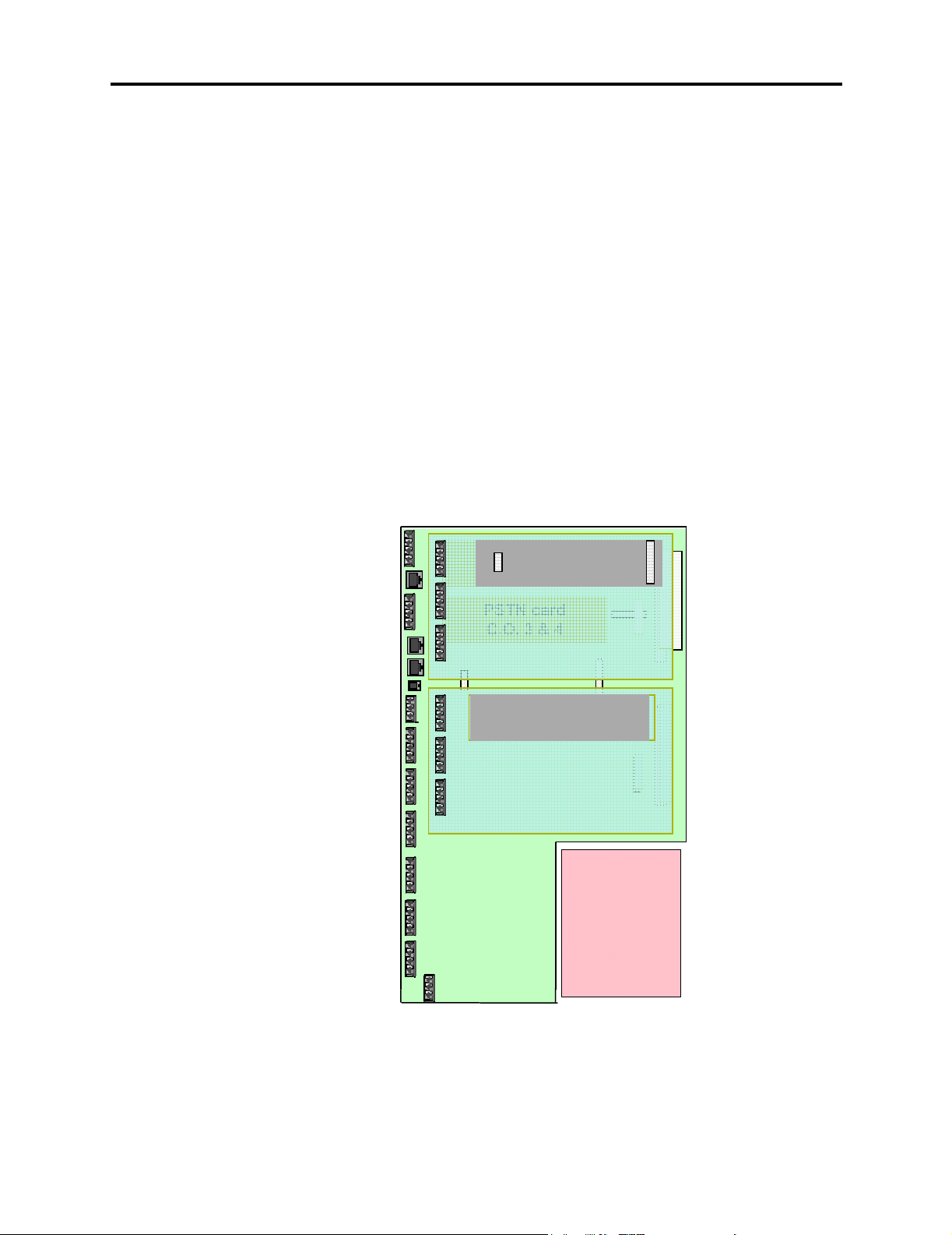
3.2 The CPU also acts as a connection platform for all system expansion cards, as shown
below. The system expansion cards are as follows:
• Extension Card: Each Extension Card provides interfaces for six extensions and a con-
nector for a Line Card. You can install up to two Extension Cards for a total of 12
extensions, in addition to the six extensions provided by the CPU.
• Line Card: This card provides interfaces for two loop start lines. You can install two
Line Cards on the CPU and one on each of the Extension Cards for a total of eight lines.
• Voice Messaging Module: This card provides up to 80 minutes of voice storage. When
installed, a system Answering Machine can be enabled and each extension can be provided with a voice message box. The Voice Messaging Module is also required to provide a personalized greeting in the Courtesy and Auto Attendant services.
PSTN card
PSTN card
Line Card
C.O. 1& 2
Lines 5 & 6
Extension Card
C.O. 3 & 4
6 Extension ports
Line Card
Lines 7 & 8
Extension Card
6 Extension ports
Power
Supply
Page 1-4
System Hardware
Page 27
4. KEYSETS
Overview
ENCORE MANUAL, Issue 4.0 – July 2002
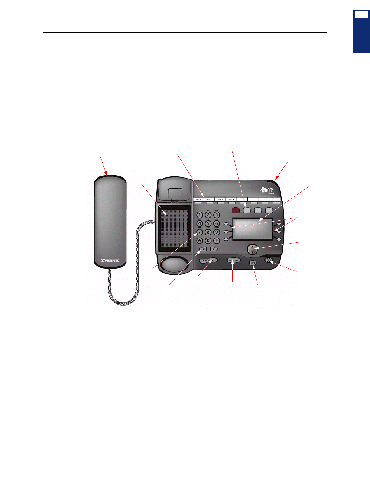
4.1 The system Keyset, shown below, is specially designed for use with the Encore system.
It features a four-line display that shows prompts and menus with selectable options. This
unique menu-driven interface makes the system simple to use – no codes are needed to program and activate features. System programming can also be performed via a Keyset using the
intuitive menu-driven interface.
4.2 The Keyset features eight Programmable Keys, which are pre-programmed to access
lines, and four Function Keys which group frequently used features in a logical manner.
4.3 The Keyset is fully handsfree, so you can make calls, receive calls, and use its features
without lifting the handset.
Function Keys: Hold, Program,
Message, and Directory
Light for ringing calls
and waiting messages
Handset
Programmable
Line/Feature Keys
1
OVERVIEW
Speaker
Keypad
Keypad Edit
Keys
Volum e
Keys
Speak er Key
with light
Display
Display Keys
Scroll Key
Microphone
Mute Key
with light
Keysets
Page 1-5
Page 28

Overview
ENCORE MANUAL, Issue 4.0 – July 2002
5. FEATURE SUMMARY
5.1 System, keyset, single-line set, and attendant features are listed below. Those features
marked with an asterisk (*) require additional equipment. For complete descriptions and operating instructions, refer to the Installation (page 2-1) and Features (page 3-1) chapters.
A. SYSTEM FEATURES
General System Features
• Flexible incoming ring assignments (alternate point answering)
• Flexible night ringing arrangement (night ring mode)
• Courtesy Service
• Variable system timers
• Internal paging
•∗ Optional Voice Messaging with:
— Customized Courtesy Service
— Answering Machine Service
— Auto-Attendant Service
•∗ Optional Doorbox
•∗ Optional door strike
•∗ Optional external music source for outside call music-on-hold
•∗ Optional external paging equipment
•∗ Optional system battery back-up
•∗ Optional long-line extension
•∗ Optional central bell
System Maintenance and Record Keeping Features
• System Programming via Keyset (defaults to Extension 20)
•∗ Optional Call Logging
•∗ Remote Management Software
Outside Call Features
• Dual-tone multi-frequency (DTMF) or dial-pulse signaling
Page 1-6
• CO line restriction
• Toll restriction
• Day and night modes of operation
• Busy CO line callback
Feature Summary
Page 29

B. EXTENSION FEATURES
• Hands-free answering of internal calls on Keysets
• On-hook dialing on Keysets
• Direct line key selection on Keysets
• System/station speed dialing
• Last number redial
• System hold
• Conference calls
• Do-not-disturb
• Camp-on and call waiting
• Call transfer
• Call forwarding
•∗ Headset compatible
Overview
ENCORE MANUAL, Issue 4.0 – July 2002
1
OVERVIEW
6. SYSTEM CAPACITIES
6.1 This table details the capacities of various system options available.
Table 1-1:
Outside Lines 8
Outgoing Line Groups 4
Internal Speech Paths 4
Extensions per System (Keysets and/or single-line sets) 18
Programming Extension (defaults to Extension 20) 1
Operator Extension (Extension 20) 1
Long-Line Extension (Extension 22) 1
Doorphone Extension (Extension 23) 1
Extension Pick-Up Groups 4
Hunt Groups 4
Voice Message Boxes (if Voice Module installed) 18
Speed Dial
— System Numbers
— Personal Numbers (per extension)
Toll Restriction
— Classes of Service
— Tables
System Capacities
Option Capacity
200
12
6
4
Extension Features
Page 1-7
Page 30

Overview
ENCORE MANUAL, Issue 4.0 – July 2002
Page 1-8
System Capacities
Page 31

Installation
ENCORE MANUAL, Issue 4.0 – July 2002
Installation
CONTENTS PAGE
1. Introduction . . . . . . . . . . . . . . . . . . . . . . . . . . . . . . . . . . . . . . . . . . . . . . . . . . . . . . . . 2-2
2. System Installation Checklist . . . . . . . . . . . . . . . . . . . . . . . . . . . . . . . . . . . . . . . . . . 2-3
3. Planning the Installation . . . . . . . . . . . . . . . . . . . . . . . . . . . . . . . . . . . . . . . . . . . . . . 2-4
A. Establish Suitable Environmental Conditions for the System . . . . . . . . . . . . . . . 2-4
B. Assemble the Necessary Tools and Supplies . . . . . . . . . . . . . . . . . . . . . . . . . . . . 2-6
4. Extension and CO Line Cabling . . . . . . . . . . . . . . . . . . . . . . . . . . . . . . . . . . . . . . . 2-7
A. Running Cable. . . . . . . . . . . . . . . . . . . . . . . . . . . . . . . . . . . . . . . . . . . . . . . . . . . . 2-7
B. Sample System Layout . . . . . . . . . . . . . . . . . . . . . . . . . . . . . . . . . . . . . . . . . . . . . 2-8
C. Terminating the Cables at Extension Locations . . . . . . . . . . . . . . . . . . . . . . . . . . 2-9
D. Performing Loop Resistance Tests . . . . . . . . . . . . . . . . . . . . . . . . . . . . . . . . . . . . 2-9
E. Wiring for Operation During Power Failure Conditions. . . . . . . . . . . . . . . . . . . 2-10
F. Signals and Tones . . . . . . . . . . . . . . . . . . . . . . . . . . . . . . . . . . . . . . . . . . . . . . . . 2-10
5. Key Service Unit (KSU) . . . . . . . . . . . . . . . . . . . . . . . . . . . . . . . . . . . . . . . . . . . . . 2-11
A. KSU Description . . . . . . . . . . . . . . . . . . . . . . . . . . . . . . . . . . . . . . . . . . . . . . . . . 2-11
B. Unpack and Inspect The KSU . . . . . . . . . . . . . . . . . . . . . . . . . . . . . . . . . . . . . . . 2-12
C. Install the Expansion Cards in the KSU . . . . . . . . . . . . . . . . . . . . . . . . . . . . . . . 2-13
D. Grounding the KSU. . . . . . . . . . . . . . . . . . . . . . . . . . . . . . . . . . . . . . . . . . . . . . . 2-16
E. Replace the KSU Cover . . . . . . . . . . . . . . . . . . . . . . . . . . . . . . . . . . . . . . . . . . . 2-17
F. Wall-Mount the KSU. . . . . . . . . . . . . . . . . . . . . . . . . . . . . . . . . . . . . . . . . . . . . . 2-18
G. Connecting Cables to the KSU . . . . . . . . . . . . . . . . . . . . . . . . . . . . . . . . . . . . . . 2-19
2
INSTALLATION
6. Keysets . . . . . . . . . . . . . . . . . . . . . . . . . . . . . . . . . . . . . . . . . . . . . . . . . . . . . . . . . . . 2-24
A. Keyset Design Features. . . . . . . . . . . . . . . . . . . . . . . . . . . . . . . . . . . . . . . . . . . . 2-24
B. Connecting the Keyset . . . . . . . . . . . . . . . . . . . . . . . . . . . . . . . . . . . . . . . . . . . . 2-24
C. Attaching the Keyset Baseplate. . . . . . . . . . . . . . . . . . . . . . . . . . . . . . . . . . . . . . 2-25
D. Wall-Mounting a Keyset . . . . . . . . . . . . . . . . . . . . . . . . . . . . . . . . . . . . . . . . . . 2-25
E. Optional Headsets . . . . . . . . . . . . . . . . . . . . . . . . . . . . . . . . . . . . . . . . . . . . . . . . 2-25
7. Single-Line Sets . . . . . . . . . . . . . . . . . . . . . . . . . . . . . . . . . . . . . . . . . . . . . . . . . . . . 2-26
8. Long-Line Extension . . . . . . . . . . . . . . . . . . . . . . . . . . . . . . . . . . . . . . . . . . . . . . . . 2-26
9. Optional Equipment. . . . . . . . . . . . . . . . . . . . . . . . . . . . . . . . . . . . . . . . . . . . . . . . . 2-26
A. Doorphone. . . . . . . . . . . . . . . . . . . . . . . . . . . . . . . . . . . . . . . . . . . . . . . . . . . . . . 2-27
B. Doorstrike . . . . . . . . . . . . . . . . . . . . . . . . . . . . . . . . . . . . . . . . . . . . . . . . . . . . . . 2-28
C. External Music-On-Hold . . . . . . . . . . . . . . . . . . . . . . . . . . . . . . . . . . . . . . . . . . . 2-29
D. Paging Equipment . . . . . . . . . . . . . . . . . . . . . . . . . . . . . . . . . . . . . . . . . . . . . . . . 2-30
E. Central Bell . . . . . . . . . . . . . . . . . . . . . . . . . . . . . . . . . . . . . . . . . . . . . . . . . . . . . 2-30
F. Call Logging Interface. . . . . . . . . . . . . . . . . . . . . . . . . . . . . . . . . . . . . . . . . . . . . 2-31
G. Programming Interface . . . . . . . . . . . . . . . . . . . . . . . . . . . . . . . . . . . . . . . . . . . . 2-31
10. Completing the Installation . . . . . . . . . . . . . . . . . . . . . . . . . . . . . . . . . . . . . . . . . . 2-32
11. Upgrading the System Software . . . . . . . . . . . . . . . . . . . . . . . . . . . . . . . . . . . . . . 2-37
12. Customer Training . . . . . . . . . . . . . . . . . . . . . . . . . . . . . . . . . . . . . . . . . . . . . . . . . 2-38
Page 2-1
Page 32

Installation
ENCORE MANUAL, Issue 4.0 – July 2002
1. INTRODUCTION
1.1 This section of the manual describes specifications and installation for the following
Encore System hardware:
• Cabling and the Main Distribution Frame (MDF)
• Key Service Unit (KSU)
• Keysets and Single-Line Sets
• Optional Equipment
This Inter-Tel Encore Installation, Programming, and Maintenance Manual instructs certi-
fied field technicians on the proper installation practices for the Encore System. This manual does not provide step-by-step instructions for premises wiring practices as dictated by
the National Electrical Code, which includes, but is not limited to, cable layouts, cable
installation, AC power installation, proper AC grounding, eliminating or preventing external interferences (including, but not limited to, RFI, EMI, lightning, AC power disturbances, static discharge), and other telephony practices standard within the industry. Cable
installers, electricians, and field technicians are expected to be properly trained and, if
applicable, licensed in their trade practices. Official Inter-Tel Encore certification is
required for technical assistance.
NOTICE
Page 2-2
Introduction
Page 33

2. SYSTEM INSTALLATION CHECKLIST
2.1 System installation is performed in the following order. Detailed instructions and fig-
ures for each step are located throughout this chapter.
! Read the safety and precaution information on page xvii.
! Plan the installation, including the Key Service Unit (KSU) location, Keyset and single-
line set locations, cable runs, and optional equipment. See page 2-4 for details.
! Run cables to the keyset and single-line set locations. See page 2-7 for details.
• Run wiring to any optional equipment, such as the external paging equipment,
external music source, long-line extension, Doorphone, doorstrike, or central bell.
• Terminate the cables on modular jack assemblies at the Keyset and single-line set
locations.
• Perform the loop resistance test for each extension’s cable.
Installation
ENCORE MANUAL, Issue 4.0 – July 2002
2
INSTALLATION
! Install system expansion cards in the KSU, as necessary, to provide the required func-
tionality. See page 2-13 for details. At minimum, you should install the following:
• At least one Line Card must be installed to make external calls.
• A Extension Card must be installed if more than six extensions, or more than four
lines are required.
• A Voice Messaging Module must be installed to provide Voice Messaging or
Answering Machine functionality.
CAUTION
Equipment Damage Hazard. Turn off the system power supply when installing
cards. Installing cards with the power on will damage the cards and void the
warranty.
! Ground the Extension Cards and KSU. See page 2-16 for details.
! Mount the KSU on the wall. See page 2-18 for details.
! Connect the extension and line cabling to the KSU. See page 2-19 for details.
! Install the telephones and any optional Keyset equipment, such as headsets. See pages
24 through 26 for details.
! Turn on the system and ensure that all equipment is working properly. See page 2-32
for details.
! Refer to the Refer to the Getting Started document to perform initial programming for
the system. See “RMS Programming” on page 5-1 and “Keyset Programming” on
page 4-1 for information on detailed system programming.
! Provide customer training. See page 2-38 for details.
System Installation Checklist
Page 2-3
Page 34

Installation
ENCORE MANUAL, Issue 4.0 – July 2002
3. PLANNING THE INSTALLATION
3.1 To make installation easier, use the following information when preparing to install the
system.
A. ESTABLISH SUITABLE ENVIRONMENTAL CONDITIONS FOR THE SYSTEM
Location
3.2 The KSU is intended for installation in a residential or office-type environment. It must
be mounted on a dry, flat wall.
3.3 Select the KSU location to minimize cable run length. Keysets and single-line sets connected to the system must not exceed a loop limit of 100 ohms (approximately 1500 feet/500
meters) using 24AWG wire. The long-line extension (Extension 22) loop limit is 366 ohms
(1.2 miles/2 kilometers). The ohm values are loop measurements; the values in parentheses are
the maximum one-way measurements from the KSU.
3.4 Allow sufficient free space all around the KSU for ventilation. Proper placement of the
wall-mount bracket, as shown below, will allow sufficient space.
4.8 in. (120mm)
clearance
20 in.
(500mm)
60 in.
(1500mm)
20 in.
(500mm)
clearance
3.5 Allow room near the KSU for the paging amplifier, battery back-up equipment, and the
external music source, if used. To avoid interference, the music source should be placed 5 to 10
feet (1.5 to 3 meters) away from the KSU. Make sure there are AC outlets for a music source
and a paging amplifier, if they are to be installed. These outlets MUST NOT be on the same
circuit as the outlet for the KSU.
Power Supply
3.6 Locate the KSU within 6 feet (2 meters) of an isolated, dedicated, 105–125VAC, 57–
63Hz, 15A, single-phase commercial power source.
Page 2-4
NOTE: This must be an isolated, dedicated AC circuit for proper operation. All three wires
(power, neutral, and ground) must be run separately from the outlet to the breaker panel without
being bonded to any other wire or circuit. DO NOT plug any other equipment into this outlet. To
maintain the protection provided by the isolated, dedicated circuit, the length of the AC power
cord limits the distance between the power supply and the outlet; DO NOT use an extension
cord.
3.7 To reduce the effects of AC voltage surges and spikes that may cause system malfunctions, false logic, and/or damage to the electronic components, a surge/spike protector is recommended.
Planning the Installation
Page 35

Supervised CO Lines
Installation
ENCORE MANUAL, Issue 4.0 – July 2002
3.8 Only supervised CO lines should be used on the Encore System. While the system has
timers that will help to prevent unsupervised trunk use, there is no implied warranty that it is
invulnerable to unauthorized intrusions and toll fraud.
3.9 If the central office does not provide supervision it will not disconnect the call when
one party hangs up; it is possible for a caller to remain connected to a CO trunk circuit. If this
happens, and the caller begins dialing, the call could be placed through the Encore System and
would then be billed to the system’s owner. The system cannot check this type of call for toll
restriction and may not register the call in the call log. This problem could arise when a call is
connected to an extension, when a call is in an unsupervised trunk-to-trunk call, or when a call
is forwarded or transferred to the public network.
Environment
3.10 The KSU, Keysets, and single-line sets require the following environmental conditions:
Table 2-1:
KSU Temperature 32° to 104° F
Telephone Temperature 32° to 113° F
Relative Humidity 5% to 95% 5% to 95%
Encore System Environmental Condition Requirements
REQUIREMENTS IN OPERATION IN STORAGE
40° to 185° F
(0° C to +40° C)
(0° C to +45° C)
(-40° C to +85° C)
40° to 185° F
(-40° C to +85° C)
NOTE: It is recommended that the maximum operating temperature (as listed above) never be
exceeded. Therefore, when installing the KSU and telephones, allow a sufficient margin for
error in case of air conditioning failure, routine mechanical maintenance, plant shutdown, etc.
As a general guideline, if the conditions are suitable for office personnel, they are also suitable
for all equipment operation. A properly controlled environment will help to extend the operating
life of the equipment.
2
INSTALLATION
3.11 Do not expose the KSU location to direct sunlight, high humidity, heat, dust, or strong
magnetic fields (such as those generated by heavy motors and large copy machines).
3.12 Ample air space should be provided for the KSU since the power supply is convection
cooled. DO NOT block the cooling vents located on the top and bottom of the KSU. Never
place anything on top of the KSU.
Establish Suitable Environmental Conditions for the System
Page 2-5
Page 36

Installation
ENCORE MANUAL, Issue 4.0 – July 2002
B. ASSEMBLE THE NECESSARY TOOLS AND SUPPLIES
3.13 You will need the following supplies and tools:
• Industry-standard, two-pair (four-conductor), twisted-pair cable to run from the KSU to
Keysets, single-line sets, and CO lines
• One or two 66M1-50-type block connectors
• Four-conductor modular jack assemblies for Keysets and single-line sets
• A high-impedance digital multimeter to check the correct wiring of the modular jack
assemblies. Multimeter accuracy must be ±0.5% or better.
• A surge/spike protector to protect the system from AC voltage surges.
• 18AWG wire for grounding
• Punch-down tools (provided) for the IDC Krone connectors
• Standard telephone hand tools and the mounting hardware for the KSU, modular jack
assemblies, etc.
• Gas discharge tubes with silicon avalanche suppressors for lightning protection on the
CO lines
• Assemble the optional equipment:
— Headsets
— External music source
— External paging speakers and amplifier
— Doorphone/door strike equipment
— Call Logging Adapter and output device
— Software, and PCs
Page 2-6
Assemble the Necessary Tools and Supplies
Page 37

4. EXTENSION AND CO LINE CABLING
Installation
ENCORE MANUAL, Issue 4.0 – July 2002
4.1 Prepare a floor plan for the Keyset and single-line set locations, using a star (home run)
configuration. Include each telephone’s extension number. Extension number 20 is assigned to
the system operator.
Avoid Fire Hazard. To reduce the risk of fire, use only 26AWG or larger line cord for CO
line connections.
A. RUNNING CABLE
4.2 A 25-pair cable is run from the CO lines and extensions and terminated on a 66M1-50-
type connecting block that is wall-mounted near the KSU. Then connections are made between
the block and the MDF section of the KSU using 25-pair cable (see page 2-19). Finally, bridging clips are installed to complete the connections on the block. This installation method provides easy access to test points for troubleshooting and minimizes the need to change puncheddown connections when moving equipment.
• CO line cabling runs from the RJ21X block to the 66M1-50-type connecting block.
NOTE: Gas discharge tubes with silicon avalanche suppressors should be installed on
all CO lines for lightning protection. Also, in areas with frequent occurrences of lightning, it is recommended that the cable between the telephone company termination and
the gas discharge tubes be at least 75 feet long (the cable may be coiled up if desired).
• All extension cables are terminated on the 66M1-50-type connecting block. The other
end of each extension cable is terminated on a four-conductor modular jack assembly at
the extension location. From the KSU location, run industry standard, two-pair (fourconductor) or 25-pair, twisted-pair cable to keysets and single-lines sets following these
guidelines:
— Install proper type cable for the application according to the National Electrical
— Avoid cable runs parallel to fluorescent light fixtures or AC lines not in conduit. If
— Do not run extension cables inside electrical conduit already occupied by AC
— Do not run cables near equipment with electric motors or through strong magnetic
— Do not run cables outdoors. The Encore System is designed for indoor wiring only.
— Do not place extension cables where they can be stepped on or where they can be
— Extension cables must not exceed a loop limit of 100 ohms (approximately 1500
2
INSTALLATION
CAUTION
Code and local building codes. If using multi-pair (e.g., 25-pair) cable runs to multiple extension locations do not include CO lines in a cable being used for extensions. Extension circuits should be included in separate multi-pair cable runs.
these obstacles are unavoidable, run the cables across them at right angles.
power cable. (To do so is a violation of the National Electrical Code.)
fields, such as those generated by large copy machines, arc welding equipment, etc.
rolled over by office furniture.
feet/500 meters) using 24AWG wire. The long-line extension (Extension 22) loop
limit is 366 ohms (1.2 miles/2 kilometers). The ohm values are loop measurements;
the values in parentheses are the maximum one-way measurements from the KSU.
NOTE: It is recommended that four-conductor modular jacks be used for all Keyset
and single-line set connections. This allows both types of telephones to be easily interchanged, if necessary. However, if desired, single-line sets can be installed using onepair cable and four-conductor modular jacks.
Extension and CO Line Cabling
Page 2-7
Page 38

Installation
ENCORE MANUAL, Issue 4.0 – July 2002
B. SAMPLE SYSTEM LAYOUT
4.3 The diagram below shows a suggested layout for the KSU and block(s). You will need
two blocks if Expansion cards are installed.
Figure 2-1. Sample Layout and Cable Assignments
CONNECTING BLOCKS
(Use bridging clips to
complete the connections)
To Extensions 26-37
on Expansion Card
Cable B to
Expansion Cards
(enters through side)
To Extensions 20-25
and devices on CPU
To Te lc o
Cable A to CPU
(enters through bottom)
Encore
Page 2-8
Sample System Layout
Page 39

ENCORE MANUAL, Issue 4.0 – July 2002
C. TERMINATING THE CABLES AT EXTENSION LOCATIONS
Installation
4.4 Terminate the keyset and single-line set cables on four-conductor modular jack assem-
blies at the extension location, as shown in the diagram below. Refer to the figure below for a
wiring diagram.
NOTE: It is recommended that four-conductor modular jacks be used for all Keyset and single-
line set connections. This allows both types of telephones to be easily interchanged, if necessary. However, if desired, single-line sets can be installed using one-pair cable and four-conductor modular jacks.
Figure 2-2. Modular Jack Assembly Wiring
DATA (O/W)
VOICE (W/BL)
G
R
VOICE (BL/W)
DATA (W/O)
FOR KEYSETS
Y
BK
VOICE
VOICE
G
R
FOR SINGLE-LINE SETS
Y
BK
2
INSTALLATION
NOTE: Single-line sets use only the Voice pair, not the Data pair.
4.5 Do not mount the assemblies on the wall at this time; they will be wall mounted later
when the telephones are installed.
D. PERFORMING LOOP RESISTANCE TESTS
NOTE: If performing the loop resistance test after the system is installed, unplug the keyset
from the jack assembly. Then disconnect the bridging clips from the 66M1-50-type connecting
block.
4.6 Perform the following loop resistance test for each individual cable:
1. Ensure that the telephone is not connected to the modular jack assembly.
2. Place a short across the RED and GREEN wires on the modular jack assembly.
3. At the connecting block, measure the resistance across the Voice pair wires. The read-
ing should not exceed 100 ohms (approximately 1500 feet/500 meters) using 24AWG
wire. The long-line extension (Extension 22) loop limit is 366 ohms (1.2 miles/2 kilometers). The ohm values are loop measurements; the values in parentheses are the maximum one-way measurements from the KSU.
NOTE: Excessive and/or improperly made connections increase the resistance of a
cable, which reduces the allowable cable run length.
4. Remove the short after the test is complete.
Terminating the Cables at Extension Locations
Page 2-9
Page 40

Installation
ENCORE MANUAL, Issue 4.0 – July 2002
E. WIRING FOR OPERATION DURING POWER FAILURE CONDITIONS
4.7 When planning the extension wiring for the system, consideration should be given to
the use of Keysets and single-line telephones in power-fail situations. As Keysets cannot operate without power, Extensions 24, 25, 31 and 37 should either have access to or be equipped
with single-line sets if they are to be used in power failure situations.
4.8 Each board with CO line capability is equipped with a power-failure circuit path. In the
event of a total system power failure, at least 50% of the equipped lines are switched to extensions. Lines 1 and 2 are connected to extensions 24 and 25, the last two extensions on the CPU.
Line 5 is connected to extension 31, and line 7 to extension 37, the last extensions on each of
the Extension Cards. These line positions are summarized in the table below.
CO LINE POWER FAILURE EXTENSION
Line 1 Extension 24
Line 2 Extension 25
Line 5 Extension 31
Line 7 Extension 37
NOTE: If lines are connected to extension positions equipped with Keysets, the user must
replace the Keyset with a single-line telephone to answer or make calls during a power failure.
Keysets cannot be used during a power failure situation.
F. SIGNALS AND TONES
Ring Signals
4.9 The system ringing signals are as follows:
TYPE OF CALL RING SIGNAL
Outside Call 2s on, 4s off
Internal Call 800 ms on, 400 ms off, 800 ms on, 4.0 seconds off
Doorphone Call 800 ms on, 5200 ms off
Recalling Call 800 ms on, 400 ms off, 800 ms on, 1000 ms off, 2000 ms
Call Processing Signals
4.10 The following signals and tones are heard through the handset or keyset speaker.
TYPE OF CALL RING SIGNAL
Dial Tone Continuous dual tone of 425 Hz ±5% and 350 Hz ±5%
Special Dial Tone
(Single-Line Sets only)
Ringback 800 ms on, 400 ms off, 800 ms on, 4s off
Busy 500 ms on, 500 ms off
Congestion 200 ms on, 200 ms off
Hold 200 ms on, 200 ms off, 200 ms on, 3.4s off
Conference One burst of 200 ms
Number Invalid 100 ms on, 100 ms off
Call Waiting 100 ms on, 4.9s off
on, 1000 ms off
900 ms on, 100 ms off of dial tone
Page 2-10
Wiring for Operation During Power Failure Conditions
Page 41

5. KEY SERVICE UNIT (KSU)
A. KSU DESCRIPTION
5.1 The KSU is a compact, wall-mounted unit that houses the system power supply, the
CPU, and the expansion cards. The KSU performs all control and switching activities for the
system, including: detecting incoming CO calls, storing speed-dial numbers, processing datacontrolled features, and controlling the interaction between keysets, single-line sets, CO lines,
and voice channels.
5.2 The KSU dimensions and weight are:
5.3 The CPU has 2MB of random-access memory (RAM) and 4MB of read-only memory
(ROM). The software code for the system is stored in the non-volatile ROM memory, and the
programmed database and speed-dial numbers are stored in the RAM memory.
Installation
ENCORE MANUAL, Issue 4.0 – July 2002
2
INSTALLATION
Height 18 in. (450 mm)
Width 12 in. (304.5 mm)
Depth 3 in. (71.6 mm)
Weight 5.5 lb. (2.5 kg)
5.4 The RAM memory is protected by a capacitor. The capacitor will protect the programmed database until the accumulated system downtime exceeds 2-3 months (depending on
the size of the database).
5.5 The connectors on the CPU are shown below. Components that are not labeled are not
currently used.
GROUNDING CONNECTOR
LINES 1 & 2
LINES 3 & 4
V24 INTERFACE
CENTRAL BELL
CONNECTOR
EXT 25
EXT 24
EXT 23
(DOORPHONE)
LINE CARD
CONNECTORS
LANGUAGE CARD
CONNECTOR
EXTENSION CARD
CONNECTORS
MUSIC-ON-HOLD
CONNECTOR
VOICE MESSAGING
MODULE CONNECTOR
Key Service Unit (KSU)
EXT 22
(LONG LINE)
EXT 21
EXT 20
STATIC DISCHARGE
STRAP CONNECTOR
DOORSTRIKE RELAY
Page 2-11
Page 42

Installation
ENCORE MANUAL, Issue 4.0 – July 2002
B. UNPACK AND INSPECT THE KSU
5.6 Before beginning the installation:
1. Unpack the KSU and lay it on a flat surface with the cover facing up.
2. Remove the MDF cover by removing the retaining screw at the bottom and sliding the
MDF cover upward. Open the KSU by loosening the two retaining screws on the left
side of the cover and lifting the cover off the hooks located on the right side. (The
screws on the KSU will not come completely out of the plastic.)
Remove the
MDF cover by
sliding upwards
Retaining screw
for MDF cover
Inter-Tel Encore
Two retaining screws
Inter-Tel Encore
Lift off cover toward right
3. Inspect the KSU. If the KSU or any of its internal components are damaged, contact
your supplier immediately.
4. Ensure that the correct Language Card is installed in the KSU. This card determines the
language that will be used by the Courtesy Service prompts (it does not affect Voice
Messaging). There are separate cards for English, Spanish, and French. See the Parts
chapter for part numbers. If the wrong Language Card is installed, replace it with the
correct card.
Page 2-12
Language Card
Location
SYSTEM MUST BE
DISCONNECTED
FROM MAINS
SUPPLY BEFORE
REMOVING LI D
5. If you are installing one or more Expansion cards, proceed to the next section. Otherwise, replace the KSU cover; then proceed to page 2-18.
Unpack and Inspect The KSU
Page 43

ENCORE MANUAL, Issue 4.0 – July 2002
C. INSTALL THE EXPANSION CARDS IN THE KSU
Installation
CAUTION
Electrostatic Discharge Hazard. The cards contain static-sensitive components. Lift them
only by the edges and carefully handle the components. Always use electrostatic protection
when inserting and removing circuit boards. Never insert or remove circuit boards when
power is applied to the system.
5.7 The KSU has circuitry for six extensions. Expansion cards add circuitry for additional
extensions and CO lines. Up to two Extension Cards and four Line Cards can be installed as
shown below.
5.8 An optional Voice Messaging Module can also be installed. This card provides up to 80
minutes of voice storage for extension voice message boxes and the Answering Machine feature. It is also used for the Automated Attendant and Custom Courtesy Service features.
Voice Messaging Module
5.9 When the Voice Messaging Module is installed, a system Answering Machine can be
enabled and each extension can be provided with a voice box. A minimum of two minutes storage is allocated automatically to each programmed extension. The remaining capacity is
dynamically allocated.
5.10 The Voice Messaging Module is also required to provide a personalized greeting in
either the Courtesy or Auto Attendant services.
2
INSTALLATION
5.11 The Voice Messaging Module is located on the CPU as shown below. To install, insert
the module into the connector on the CPU.
Voice Messaging
Module Location
Install the Expansion Cards in the KSU
Page 2-13
Page 44

Installation
ENCORE MANUAL, Issue 4.0 – July 2002
Line Card
5.12 The Line card adds two CO lines to the system. Because the CPU does not have CO
line connectors, at least one Line Card must be installed for CO line access. Line Cards can be
installed on the CPU or on Extension Cards, as shown below.
Locate Line Card
Here
Locate Line Card
Here
Locate Line Card
Here
Locate Line Card
Here
NOTE: If only one line on a two-port Line Card will be used, the second line must be disabled
using system programming.
5.13 To install, insert the Line Card into one of the connectors on the CPU or a connector on
a Extension Card.
TOP
Insert this
way
Page 2-14
Install the Expansion Cards in the KSU
Page 45

Extension Card
Installation
ENCORE MANUAL, Issue 4.0 – July 2002
5.14 Each Extension Card has circuitry for an additional six extensions. Up to two Extension
Cards can be installed.
Position 1
Position 2
2
INSTALLATION
5.15 The Extension Card has a grounding connector, Line Card and line connectors, and six
extension connectors. The figure below shows the Extension Card connectors. The six extensions are numbered 26 through 31 for the card in the lower connector on the CPU and 32
through 37 for the card in the upper connector.
Grounding Connector
Line Connector
Line Card Connectors
Six Extension
Connectors
Install the Expansion Cards in the KSU
Page 2-15
Page 46

Installation
ENCORE MANUAL, Issue 4.0 – July 2002
5.16 To install, insert the Extension Card into the connectors on the CPU. The card must be
inserted with the column support located under the line termination points as shown below.
NOTE: To protect the system against high voltage surges on incoming CO lines (for example,
caused by lightning), the ground connector on the Extension Cards must be connected to the
grounding point on the CPU. Then the CPU must be attached to earth ground. It should also be
equipped with a surge/spike protector (see next page).
D. GROUNDING THE KSU
5.17 To protect the system against high voltage surges on incoming CO lines (for example,
caused by lightning), the ground connector on the Extension Cards must be connected to the
grounding point on the CPU. Then the CPU must be attached to earth ground. It should also be
equipped with a surge/spike protector.
5.18 To ground the cards and CPU, run wire to the grounding terminals as shown below.
Then connect the grounding terminal on the CPU to an earth ground.
To Earth Ground
PSTN Expansion
Card
PSTN Expansion
Card
Page 2-16
Grounding the KSU
Page 47

E. REPLACE THE KSU COVER
Installation
ENCORE MANUAL, Issue 4.0 – July 2002
5.19 If expansion cards have been installed in the KSU, you must remove the break-off pan-
els from the side of the KSU cover to allow access to the connectors.
Break-Off Panels
Encore
5.20 Position the cover over the hooks on the right edge of the KSU and then lower the cover
onto the KSU. Tighten the retaining screws on the cover.
2
INSTALLATION
Replace the KSU Cover
Two retaining screws
Inter-Tel Encore
Page 2-17
Page 48

Installation
ENCORE MANUAL, Issue 4.0 – July 2002
F. WALL-MOUNT THE KSU
5.21 When a suitable location has been found, mark the screw locations on the mounting sur-
face, using the mounting bracket provided. Position the bracket on the wall and ensure that it is
level. Mark the screw holes, then drill four holes in the wall at the marked locations. If the
KSU is being mounted on masonry or plasterboard, use suitable fasteners.
5.22 The figure below shows the mounting bracket and the necessary top and side clearances.
20 in.
(500mm)
4.8 in. (120mm)
clearance
60 in.
(1500mm)
20 in.
(500mm)
clearance
5.23 Hang the KSU on the bracket, as shown in the figure below.
Locate the mounting bracket in a
suitable position and place the KSU
onto it by lowering it into position
Inter-Tel Encore
Page 2-18
Wall-Mount the KSU
Page 49

G. CONNECTING CABLES TO THE KSU
Installation
ENCORE MANUAL, Issue 4.0 – July 2002
Wiring Technique
5.24 The extension and line cables connected to the CPU enter the KSU at the bottom of the
KSU, as shown below. Remove the break-out panel at the bottom of the KSU and pass the
cables that will be connected to the CPU through the cable entry hole.
CAUTION
Safety Hazard. Remove only the knock-out panel(s) required for cable access to the KSU
MDF area. Removing the other panels exposes the KSU circuitry unnecessarily and could
create a safety hazard.
5.25 Cables that will be attached to the Extension Cards are routed from the left side of the
KSU, directly to the cards. (The breakout panels on the side are removed to allow access to the
Extension Cards.)
5.26 Pass cable-retaining straps through the hooks provided and pass the cables through the
cable-retaining straps until they are adjacent to the appropriate connectors. The cables should
be neatly guided into the channel space between the connectors and the KSU case side, ensuring that there is sufficient clearance between the cables and the KSU case lid. The cables
should remain sheathed inside the KSU housing to within reach of the appropriate connector.
2
INSTALLATION
Install cables along the left
side of the KSU, (area in gray),
and connect to the appropriate
terminals
5.27 The tables on the following pages show the connection points between the CPU con-
nectors in the KSU and the 66M1-50-type connecting block, using the standard 25 pair cable
color code.
Connectors
5.28 The KSU and Extension Cards are equipped with 4-wire IDC Krone connectors. The
same connector type is used to terminate the CO lines as is used to terminate the extensions. To
punch down the extension and line cables on the IDC Krone connectors, use the special punchdown tool, provided with the KSU.
Connecting Cables to the KSU
Cable access via a break-out panel on bottom left
of the KSU housing
Page 2-19
Page 50

Installation
ENCORE MANUAL, Issue 4.0 – July 2002
FIGURE 3. Main CPU Connections — Cable A
Table 2-2: Main CPU Connections - Cable A
CABLE PAIR CONNECTION DEVICE
W-BL VOICE-A
BL-W VOICE-B
W-O DATA-C
O-W DATA-D
W-G VOICE-A
G-W VOICE-B
W-BR DATA-C
BR-W DATA-D
W-S VOICE-A
S-W VOICE-B
R-BL DATA-C
BL-R DATA-D
R-O VOICE-A
O-R VOICE-B
R-G DATA-C
G-R DATA-D
R-BR VOICE-A
BR-R VOICE-B
R-S DATA-C
S-R DATA-D
BK-BL VOICE-A
BL-BK VOICE-B
BL-O DATA-C
O-BK DATA-D
BK-G
G-BK
BK-BR
BR-BK
BK-S
S-BK
Y-BL
BL-Y
Y-O
O-Y
Y-G TIP Line
G-Y RING
Y-BR TIP Li ne
BR-Y RING
Y-S TIP Line
S-Y RING
V-BL TIP Lin e
BL - V RING
V-O TIP Line
O - V RING
V-G TIP Line
G - V RING
V-BR TIP Line
BR - V RING
V-S TIP Line
S - V RING
MOH Music Source
CENTRAL BELL
DOOR STRIKE
Not Used None
Ext 20
Ext 21
Ext 22
Ext 23
Ext 24
Ext 25
Central
Bell
Door
Strike
#1
#2
#3
#4
#5
#6
#7
#8
Page 2-20
Main CPU Connections — Cable A
Page 51

FIGURE 4. Expansion Card Connections — Cable B
Installation
ENCORE MANUAL, Issue 4.0 – July 2002
Table 2-3: Expansion Card Connections - Cable B
CABLE PAIR CONNECTION DEVICE
W-BL VOICE-A
BL-W VOICE-B
W-O DATA-C
O-W DATA-D
W-G VOICE-A
G-W VOICE-B
W-BR DATA-C
BR-W DATA-D
W-S VOICE-A
S-W VOICE-B
R-BL DATA-C
BL-R DATA-D
R-O VOICE-A
O-R VOICE-B
R-G DATA-C
G-R DATA-D
R-BR VOICE-A
BR-R VOICE-B
R-S DATA-C
S-R DATA-D
BK-BL VOICE-A
BL-BK VOICE-B
BL-O DATA-C
O-BK DATA-D
BK-G VOICE-A
G-BK VOICE-B
BK-BR DATA-C
BR-BK DATA-D
BK-S VOICE-A
S-BK VOICE-B
Y-BL DATA -C
BL-Y DATA-D
Y-O VO IC E- A
O-Y VOICE-B
Y-G DATA -C
G-Y DATA-D
Y-BR VOICE-A
BR-Y VOICE-B
Y-S D ATA- C
S-Y DATA-D
V-BL VOICE-A
BL - V VOICE-B
V-O DATA-C
O - V DATA-D
V-G VOICE-A
G - V VOICE-B
V-B R DATA-C
BR - V DATA - D
V-S
S - V
Not Used None
Ext 26
Ext 27
Ext 28
Ext 29
Ext 30
Ext 31
Ext 32
Ext 33
Ext 34
Ext 35
Ext 36
Ext 37
2
INSTALLATION
Expansion Card Connections — Cable B
Page 2-21
Page 52

Installation
ENCORE MANUAL, Issue 4.0 – July 2002
CO Line Connections
5.29 The first A and B pair on each Line Card is used to terminate one line and the second C
and D pair is used to terminate a second line. Refer to the chart on page 2-20 for wiring connections.
5.30 CO lines 1 to 4 are terminated in the CPU connectors, as shown below. The cables for
these connections are routed into the KSU through the breakout panel at the bottom.
Line 1
A
B
Line 2
C
D
Line
Card
Line
Card
A
Line 3
B
Line 4
C
D
5.31 CO lines 5 to 8 are terminated on the two Extension Cards, as shown below. The first
Extension Card provides a connector for lines 5 and 6 and the second Extension Card provides
a connector for lines 7 and 8. The cables for these connections are routed into the KSU from
the left, through the breakout panels on the KSU cover.
Page 2-22
AB C D
Line 5
Line 6
AB C D
Line 7
Line 8
PSTN Expansion
Card
Line Card
PSTN Expansion
Card
Extension
Cards
Line Card
Expansion Card Connections — Cable B
Page 53

Extension Connections
Installation
ENCORE MANUAL, Issue 4.0 – July 2002
5.32 Extensions 20 to 25 are terminated on the CPU, as shown below. Note that extensions
are numbered from the bottom up. Refer to the charts on pages 20 and 21 for wiring connections. The cables for these connections are routed into the KSU through the breakout panel at
the bottom.
A
Ext 25
B
Extensions
C
20-25
D
Ext 20
5.33 Extensions 26 to 37 are terminated on the Extension Cards, as shown below. The cables
for these connections are routed into the KSU from the left, through the breakout panels on the
KSU cover.
2
INSTALLATION
PSTN Expansion
Card
Ext 31
AB C D
AB C D
Extensions
26-31
Extensions
32-37
PSTN Expansion
Card
Ext 26
Ext 37
Ext 32
Extension
Cards
5.34 The A&B and C&D connections are used for Keysets. Single-line sets require only the
A&B connections.
Expansion Card Connections — Cable B
Page 2-23
Page 54

Installation
ENCORE MANUAL, Issue 4.0 – July 2002
6. KEYSETS
6.1 The system has capacity for up to 18 extensions. Extensions can be equipped with
Encore Keysets or industry-standard single-line sets.
A. KEYSET DESIGN FEATURES
Integrated Speakerphone
6.2 A built-in, integrated speakerphone is standard in the Keysets. It allows users to place
and receive internal calls without lifting the handset. Once a call is connected, the Keyset user
may speak handsfree over the speakerphone or lift the handset to speak privately.
6.3 When using the handset, the user may switch to the speakerphone by pressing the
Speaker key and replacing the handset. If enabled, pages may be broadcast over the speaker
when the phone is not being used.
Liquid Crystal Display (LCD)
6.4 Each Keyset has a liquid crystal display (LCD). The display helps the user to process
calls more efficiently. There are display messages for date and time, numbers dialed, incoming
calls, extension and system status, features, and programming. These displays are indicated
throughout the Features section of the manual.
B. CONNECTING THE KEYSET
6.5 Ensure that the extension loop resistance test has been performed before installing the
keysets. (See page 2-9.)
6.6 Install all keysets as follows:
1. Mount the modular jack assembly on the wall.
2. Plug one end of the coiled handset cord into the handset jack on the left side of the key-
set. Plug the other end into the handset. Place the handset on hook.
3. Plug one end of the keyset line cord into the modular jack. Plug the other end into the
line cord jack.
4. After all keysets are installed, turn on the KSU AC power switch.
5VDC Power Supply
Connector
Modem/Data Port
DC
L2
TAPI
Line Cord Jack
L1
Handset Jack
Page 2-24
Keysets
Page 55

C. ATTACHING THE KEYSET BASEPLATE
Installation
ENCORE MANUAL, Issue 4.0 – July 2002
6.7 There are retaining clips on the baseplate that allow it to be attached to the keyset at two
different angles. When the correct viewing angle has been selected, clip the baseplate onto
either the lower or upper slot on the underside of the Keyset.
Lower Setting
Bottom view of Keyset
D. WALL-MOUNTING A KEYSET
6.8 Locate, drill and plug the two screw locations as shown below. The holes should be
deep enough to accept a 1-inch (25 mm) screw. Install the two screws, leaving .25 to .75 inches
(3 or 4 mm) protruding. Remove the baseplate from the base of the phone and position the two
keyhole slots on the base of the Keyset over the two screws. (The baseplate is not used.) Then
slide the keyset into place.
2
INSTALLATION
Upper Setting
Side view of Baseplate
6.32 in. (158mm)
6.9 The handset retaining clip, located directly below the hookswitch, must be reversed so
that the handset is secure when the phone is wall-mounted.
6.10 When the Keyset is wall mounted, you can hang the handset on the top edge of the
Keyset housing if you need to set the handset down during a call.
E. OPTIONAL HEADSETS
6.11 The Keysets are compatible with industry-standard, four-conductor, modular headsets
that have electret microphones.
6.12 To attach a headset to a keyset:
1. Remove the coiled handset cord from the handset jack on the base of the keyset. Leave
the handset in the cradle.
2. Insert the headset modular plug into the handset jack. Plug in the headset power source,
if used.
3. If the headset has an on/off switch, turn on the headset.
Attaching the Keyset Baseplate
Page 2-25
Page 56

Installation
ENCORE MANUAL, Issue 4.0 – July 2002
7. SINGLE-LINE SETS
7.1 Industry-standard, AC-ringing, single-line DTMF sets may be installed on an Encore
System.
7.2 Single-line set users access features simply by lifting the handset and entering a feature
code or by using a combination of a hookflash and a feature code. Refer to the Features section
of this manual (page 3-1) for details.
7.3 To install a single-line set:
1. Mount the modular jack assembly on the wall.
2. Plug one end of the line cord into the modular jack assembly and plug the other end into
the jack on the single-line set.
8. LONG-LINE EXTENSION
8.1 Extension 22 is designed to work with a single-line telephone at a distance of up to 1.2
miles (2 km) away from the KSU.
• If Extension 22 is used as a long-line extension, a single-line telephone extension must
be used.
• The maximum cabling distance is 1.2 miles (2 km), 330 ohms, or 3 dB at 1600 Hz. Distance assumes 24 AWG (0.5 mm) diameter copper cabling.
• The cabling must be internal.
9. OPTIONAL EQUIPMENT
9.1 The following optional system equipment can be installed:
• Doorphone
• Doorstrike
• External Music Source
• External Paging Equipment
• Central Bell
• Call Logging Output Device
Page 2-26
Single-Line Sets
Page 57

A. DOORPHONE
Installation
ENCORE MANUAL, Issue 4.0 – July 2002
9.2 An external Doorphone is available that can be installed on the Encore System. (See
PARTS for part numbers.) When a person presses a button on the Doorphone, the unit generates ringing on the extensions programmed to receive Doorphone calls. After answering the
ringing call, a system user can talk with the person at the door.
9.3 In database programming, make sure that the desired keysets have access to the Doorphone. Refer to page 4-13 for details. The Doorphone can be mounted using the supplied
bracket.
Doorphone Bracket
Mounting
Screw
9.4 To install the Doorphone, connect the single pair from the Doorphone to the A and B
connections of Extension 23 on the CPU.
2
INSTALLATION
Doorphone
To the
Doorphone
A
B
Ext 23
Page 2-27
Page 58

Installation
ENCORE MANUAL, Issue 4.0 – July 2002
B. DOORSTRIKE
9.5 The doorstrike two-way connector provides a closed relay contact when in the operated
condition. The relay contact is suited only for use with low voltage DC equipment. (Rating:
24VDC, 2 Amps).
9.6 If the door is equipped with an electric strike plate, a system user may open the door by
dialing a code or pressing a feature button.
NOTE: You must purchase the doorstrike mechanism and arrange for a qualified electrician to
install it. Also, for security reasons, be careful not to place an extension, that can open the doorstrike, too close to a window or other point of access.
9.7 The leads from the CPU A and B connector are connected to the doorstrike, as shown
below. This is the connector used for the optional doorstrike mechanism.
Page 2-28
To the
Doorstrike
A
B
Doorstrike
Page 59

C. EXTERNAL MUSIC-ON-HOLD
Installation
ENCORE MANUAL, Issue 4.0 – July 2002
9.8 If a customer-provided music source is not installed, the internal music-on-hold cir-
cuitry provides music for CO lines on hold. However, an external source (such as a radio, tape
player, etc.) can be installed and programmed to provide music-on-hold.
9.9 The music source is connected to the CPU using a fixed-screw terminal.
To M u s i c
Source
Fixed-screw
terminal
2
INSTALLATION
9.10 The music-on-hold circuitry automatically holds the volume to a predetermined level
that is slightly lower than normal voice volume, as required by FCC regulations.
NOTE: In some circumstances, there may be broadcast restrictions associated with the music.
Check with the music’s original distributor and/or the radio station for copyright and broadcast
restrictions concerning music-on-hold.
9.11 If using a radio as a music source, place it five to 10 feet away from the KSU to avoid
RFI generated by the KSU. If the radio is placed more than 10 feet away from the KSU, use
twisted-pair cable. For better reception, a radio with an external antenna is recommended.
9.12 To install the music source:
1. Using a 5- to 10-foot (1.5- to 3.0-meter) length of coaxial cable, connect one end of the
cable to the speaker output terminals of the music source.
NOTE: If the music source has an earphone jack, you can attach an 1/8-inch mini
phone plug or other specified connector and plug it into the earphone jack on the music
source. However, if the earphone jack is “padded” so that the optimal volume level cannot be reached, the procedure above may be most effective.
2. Attach the other end of the coaxial cable to the two-pin screw terminal on the CPU.
3. Plug in the AC power cord for the music source. DO NOT use the outlet for the KSU.
4. Turn on the AC power to the music source.
5. Enable music-on-hold at the Programming Keyset (see page 4-10 for procedures).
6. From a keyset, select a CO line and dial the telephone number of one of the other lines
External Music-On-Hold
to call back into the system. Put the call on hold to hear the music. Adjust the volume
on the music source to the desired level. The optimum input level is 1.0VRMS (0dB).
Page 2-29
Page 60

Installation
ENCORE MANUAL, Issue 4.0 – July 2002
D. PAGING EQUIPMENT
9.13 The Encore can be configured to operate with external paging equipment (speaker and
amplifier). The paging equipment can be connected to any extension position.
9.14 To install the external paging equipment:
1. Cut a length of shielded speaker cable (or coaxial cable) to run from the paging amplifier to the KSU.
2. Connect one end of the cable to the amplifier high-impedance input according the manufacturer’s instructions.
3. Connect the other end of the cable to an extension connector on the CPU or Extension
Card.
4. Connect the speaker(s) to the amplifier, using speaker cable.
5. Plug in the amplifier’s AC power cord. DO NOT use the outlet for the KSU.
6. Set the amplifier volume control to the lowest setting and turn on the amplifier.
7. Enable the Paging equipment in system programming (see page 4-13 for details).
8. From a keyset, make a page. Adjust the amplifier to the desired level while placing the
page.
E. CENTRAL BELL
9.15 The CPU has a connector that supplies a ringing signal when the Central Bell is pro-
grammed to ring for an incoming call on a line or line group (refer to page 4-25 for details).
The Central Bell is connected to the KSU, as shown below.
To the
Central Bell
A
B
Page 2-30
Paging Equipment
Page 61

F. CALL LOGGING INTERFACE
Installation
ENCORE MANUAL, Issue 4.0 – July 2002
9.16 If desired, an optional Call Logging Adapter and a output device (printer, terminal, etc.)
can be connected to the Encore System to provide call records. The device allows the programmer to print useful call information. See page 3-47 for more details.
9.17 The Call Logging connection is programmable to use 4800, 9600, or 19200 (default)
bps. Other communications settings are: 8 bits, no parity, and 1 stop bit.
9.18 The Call Logging Interface is attached to the CPU using a V24 Adapter and a 3-foot (1meter) RJ22-to-RJ22 cable, as shown below.
2
INSTALLATION
NOTE: A standard DB-9 to DB-25 converter connector can be used to connect the external
serial port to output device that is not equipped with a DB-9 connector.
9.19 The V24 Adapter has the following pinout:
Table 2-4:
V24 CONNECTOR PIN DESCRIPTION 25-PIN CONNECTOR
V24 Adapter Pinouts
Pin 1 DCD Data Carrier Detect Pin 8
Pin 2 Receive Data Pin 3
Pin 3 Transmit Data Pin 2
Pin 4 DTR Data Terminal Ready Pin 20
Pin 5 Signal Ground Pin 7
Pin 6 DSR Data Set Ready Pin 6
Pin 7 RTS Request To Send Pin 4
Pin 8 CTS Clear To Send Pin 5
Pin 9 RI Ring Indicate Pin 22
G. PROGRAMMING INTERFACE
9.20 If desired, the V24 Adapter (shown above) and a PC with Remote Management Soft-
ware can be connected to an Encore Keyset to provide remote programming and maintenance.
For details, refer to “RMS Programming” on page 5-1.
Call Logging Interface
Page 2-31
Page 62

Installation
ENCORE MANUAL, Issue 4.0 – July 2002
10. COMPLETING THE INSTALLATION
10.1 To complete the system installation:
1. Using suitable precautions against electrostatic discharge, ensure that all system expansion cards are secured correctly and that all column supports are installed to their relevant positions.
2. Verify all extension and line terminations on the connecting block and the KSU.
3. Ensure there are no screws or metal objects loose within the KSU housing because
these may cause damage on power up.
4. Power up and test the system:
a. Plug in the KSU power supply.
b. Wait 8-10 seconds for the system power up routine to complete. During this period,
you will hear several clicks as relays are energized.
c. Check that the Vital Activity LED on the CPU is flashing (see below).
d. The system Keyset displays will show the product name and software revision for
about 1.5 seconds.
Vital Activity LED
5. Remove any anti-scratch protective film from all Keyset displays.
Page 2-32
6. Label all Keysets.
7. Reset the system. (See page 4-14 for details).
8. Ensure that all Keysets provide dial tone, ringing, and handsfree operation. Check that
the display is not showing corrupt information.
9. Check that all single-line telephones are providing dial tone and ringing.
Completing the Installation
Page 63

Installation
ENCORE MANUAL, Issue 4.0 – July 2002
10. Perform basic programming. Planning sheets are provided so you can record the set-
tings. Refer to the Programming chapters (“Keyset Programming” on page 4-1 and
“RMS Programming” on page 5-1) to perform additional programming changes from
the default, as required.
a. Disconnect line interfaces that have no CO lines connected. (See page 5-31.) The
system assumes that all Line Cards have CO lines connected to them.
b. Program extensions and call routing.
Program extensions using RMS. Refer to page 5-17 for information. Use the planning sheet below to record your settings.
2
INSTALLATION
Table 3:
EXTENSION NAME FORWARD BUSY FORWARD BUSY/NO ANSWER MANAGER (IF SECTY)
* Extension 23 is the Doorphone.
Call Handling/Extension Names
20
21
22
23*
24
25
26
27
28
29
30
31
32
33
34
35
36
37
Completing the Installation
Page 2-33
Page 64

Installation
ENCORE MANUAL, Issue 4.0 – July 2002
c. Enable and/or disable features.
Enable or disable desired features using RMS. Refer to page 5-19 for information.
Use the planning sheet below to record your settings.
Place a check mark in the box to indicate which extensions will have each of the
features enabled.
Table 4:
Tone Protect
Page Protection
General Call Protection
Extension Disconnect
No Call Logging
No Trunk-to-Trunk Calls
Personal Caller ID List
Voice Messaging
System Speed Dial Override
Restrict Use Of PA
Door Restrict
Voice Mail Password
Reminder Call
Extension Lock Code
Voice Message Ports
* Extension 23 is the Doorphone.
Enabled/Disabled Features
PROGRAMMING OPTION 20 21 22 23* 24 25 26 27 28 29 30 31 32 33 34 35 36 37
d. Equip lines and telephone numbers.
Equip lines and telephone numbers using RMS. Refer to page 5-31 for information
on equipping lines. Refer to page 5-37 for information on setting caller ID detection. Use the planning sheet below to record your settings.
TABLE 5. Equipped Lines, Telephone Numbers and Caller ID
Page 2-34
EQUIPPED? TELEPHONE NUMBER CALLER ID DETECTION
Line 1
Line 2
Line 3
Line 4
Line 5
Line 6
Line 7
Line 8
Completing the Installation
Page 65

ENCORE MANUAL, Issue 4.0 – July 2002
e. Program answering machine and courtesy service.
Installation
Refer to page 5-31 for information on programming the answering machine and
courtesy service features. Use the planning sheet below to record your settings.
TABLE 6. Answering Machine, Courtesy Service and Auto Attendant
ANSWERING
MACHINE
LINE
Enabled Disabled
Line 1
Line 2
Line 3
Line 4
Line 5
Line 6
Line 7
Line 8
f. Program system-wide features.
Refer to page 5-37 for information on programming system-wide features. Use the
planning sheet below to record your settings.
COURTESY SERVICE (DAY/
Voice Module
Source
NIGHT)
Internal
Source
2
INSTALLATION
AUTO
ATTENDANT
Day Night
Enabled Disabled Enabled Disabled
TABLE 7. System-wide Features
PROGRAMMING OPTION ALLOWED VALUES PROGRAMMED VALUE
Weekend Service
Flashing Hold LED
Call Logging
Store All Calls (Caller ID)
Doorphone
System Voicebox On (Answering Machine)
911 & Extension Sending
Night Service
Night Service On and Off Times HH:MM (24-Hour format)
Music On Hold Internal source, External source,
Programming Position Any equipped extension
Paging Amplifier Position Any extension
System Programming Password Four digits
Set V24 Baud Rate 4800, 9600, 19200
Courtesy Service Source Voice Module or Internal
Sales Telephone Number
Service Telephone Number
Message Capacity 10 – 50
Group Divert to System Box On or Off
On or Off
Tone on hold, or Silence
Completing the Installation
Page 2-35
Page 66

Installation
ENCORE MANUAL, Issue 4.0 – July 2002
g. Record greetings.
Refer to page 4-11 for information on programming system-wide features. Use the
planning sheet below to record your settings.
TABLE 8. Recorded Greetings
GREETING MESSAGE
Auto Attendant Day Greeting
Auto Attendant Night
Courtesy Service Day
Courtesy Service Night
Directory Message
Page 2-36
Completing the Installation
Page 67

11. UPGRADING THE SYSTEM SOFTWARE
NOTE: Check that RMS is installed before performing this procedure.
11.1 To upgrade the system software:
1. Ensure your phone system PC meets the following requirements for the upgrade version
of the Remote Management Software.
• PC with Remote Management Software for Service Centers (RMS v2.0.8x).
• V24 adapter and cables
• Software version 4.0 files (4.0x_1.fdl and 4.0x_2.fdl)
• Flat screw driver
• Electrostatic Discharge (ESD) wrist strap
2. Record and/or save the customer database and programming details. System speed dials
can be saved and restored using RMS.
Installation
ENCORE MANUAL, Issue 4.0 – July 2002
2
INSTALLATION
3. Download Flash files. Disable Power Management features if you are using a laptop.
• Copy the files 4.0x_1.fdl and 4.0x_2.fdl to the Remote Maintenance Soft-
ware directory or a directory on the PC hard disk (the files must be located in the
same directory).
• Connect to the KSU using RMS and the V24 connection.
• From the RMS main menu, select Options – Download Flash.
• Browse to the flash files (.fdl files).
• Select 4.0x_1.fdl.
• Select the download flash option. The files 4.0x_1.fdl and 4.0x_2.fdl are
automatically downloaded to the KSU.
The flash download takes approximately 25 minutes. The system alerts you when
the flash is finished.
• Click OK.
NOTE: The download drops the connection between the PC and the KSU.
4. Connect to the KSU. From the RMS main menu, select Diagnostic Menu – Cold
Reset.
NOTE: The reset drops the connection between the PC and the KSU.
5. Restore system speed dials using RMS (page 5-42). When finished, exit RMS.
6. Proceed to
Upgrading the System Software
“Upgrading the RMS Software” on page 5-4.
Page 2-37
Page 68

Installation
ENCORE MANUAL, Issue 4.0 – July 2002
12. CUSTOMER TRAINING
12.1 After you complete the installation, make sure the customer is trained to use the system.
At minimum, this should cover the following:
• Use of the Keyset menus and associated keys
• Receiving, making, and transferring calls
• Accessing system programming
• Use of Voice Messaging features
12.2 Explain the features using the Encore Installation, Programming, and Maintenance
Manual and the Encore User Guide. All manuals are provided on the Encore CD-ROM. You
will need a free Adobe Acrobat Reader to access the files.
Page 2-38
Customer Training
Page 69

Features
ENCORE MANUAL, Issue 4.0 – July 2002
Features
CONTENTS PAGE
1. Introduction . . . . . . . . . . . . . . . . . . . . . . . . . . . . . . . . . . . . . . . . . . . . . . . . . . . . . . . . 2-3
2. Feature Keys and Codes. . . . . . . . . . . . . . . . . . . . . . . . . . . . . . . . . . . . . . . . . . . . . . . 2-3
A. Feature Codes . . . . . . . . . . . . . . . . . . . . . . . . . . . . . . . . . . . . . . . . . . . . . . . . . . . . 2-3
B. Single-Line Only Codes . . . . . . . . . . . . . . . . . . . . . . . . . . . . . . . . . . . . . . . . . . . . 2-4
C. Operator-Only Codes . . . . . . . . . . . . . . . . . . . . . . . . . . . . . . . . . . . . . . . . . . . . . . 2-4
D. Extension Numbers . . . . . . . . . . . . . . . . . . . . . . . . . . . . . . . . . . . . . . . . . . . . . . . . 2-4
E. Outgoing Line Access . . . . . . . . . . . . . . . . . . . . . . . . . . . . . . . . . . . . . . . . . . . . . 2-4
3. CO Line Features . . . . . . . . . . . . . . . . . . . . . . . . . . . . . . . . . . . . . . . . . . . . . . . . . . . . 2-5
A. Dual-Tone Multi-Frequency (DTMF) or Dial-Pulse Signaling . . . . . . . . . . . . . . 2-5
B. Flexible Incoming Ring Assignment. . . . . . . . . . . . . . . . . . . . . . . . . . . . . . . . . . . 2-5
C. Outgoing Line Groups. . . . . . . . . . . . . . . . . . . . . . . . . . . . . . . . . . . . . . . . . . . . . . 2-5
D. Day and Night Modes and Weekend Service . . . . . . . . . . . . . . . . . . . . . . . . . . . . 2-5
E. Outgoing Line Access/Restriction . . . . . . . . . . . . . . . . . . . . . . . . . . . . . . . . . . . . 2-6
F. Toll Restriction Classes Of Service. . . . . . . . . . . . . . . . . . . . . . . . . . . . . . . . . . . . 2-6
G. Caller ID . . . . . . . . . . . . . . . . . . . . . . . . . . . . . . . . . . . . . . . . . . . . . . . . . . . . . . . . 2-7
H. Alternative Call Routing . . . . . . . . . . . . . . . . . . . . . . . . . . . . . . . . . . . . . . . . . . . . 2-9
I. Operation with a Parent PBX . . . . . . . . . . . . . . . . . . . . . . . . . . . . . . . . . . . . . . . . 2-9
4. Protection Against Power Failure . . . . . . . . . . . . . . . . . . . . . . . . . . . . . . . . . . . . . 2-10
A. Database Protection. . . . . . . . . . . . . . . . . . . . . . . . . . . . . . . . . . . . . . . . . . . . . . . 2-10
B. Power Failure Telephones . . . . . . . . . . . . . . . . . . . . . . . . . . . . . . . . . . . . . . . . . . 2-10
5. Extensions . . . . . . . . . . . . . . . . . . . . . . . . . . . . . . . . . . . . . . . . . . . . . . . . . . . . . . . . . 2-11
A. Keysets . . . . . . . . . . . . . . . . . . . . . . . . . . . . . . . . . . . . . . . . . . . . . . . . . . . . . . . . 2-11
B. Single-Line Sets . . . . . . . . . . . . . . . . . . . . . . . . . . . . . . . . . . . . . . . . . . . . . . . . . 2-16
C. Doorphone Units . . . . . . . . . . . . . . . . . . . . . . . . . . . . . . . . . . . . . . . . . . . . . . . . . 2-17
D. Hot Line Extensions . . . . . . . . . . . . . . . . . . . . . . . . . . . . . . . . . . . . . . . . . . . . . . 2-17
6. Courtesy Service . . . . . . . . . . . . . . . . . . . . . . . . . . . . . . . . . . . . . . . . . . . . . . . . . . . 2-18
3
FEATURES
7. Voice Messaging Module Features . . . . . . . . . . . . . . . . . . . . . . . . . . . . . . . . . . . . . 2-19
A. Automated Attendant . . . . . . . . . . . . . . . . . . . . . . . . . . . . . . . . . . . . . . . . . . . . . 2-19
B. Answering Machine . . . . . . . . . . . . . . . . . . . . . . . . . . . . . . . . . . . . . . . . . . . . . . 2-20
C. Voice Messaging . . . . . . . . . . . . . . . . . . . . . . . . . . . . . . . . . . . . . . . . . . . . . . . . . 2-20
8. Music-On-Hold . . . . . . . . . . . . . . . . . . . . . . . . . . . . . . . . . . . . . . . . . . . . . . . . . . . . 2-23
9. Internal Calls . . . . . . . . . . . . . . . . . . . . . . . . . . . . . . . . . . . . . . . . . . . . . . . . . . . . . . 2-23
A. Keyset Handsfree Enable/Disable. . . . . . . . . . . . . . . . . . . . . . . . . . . . . . . . . . . . 2-23
B. Extension-To-Extension Calling . . . . . . . . . . . . . . . . . . . . . . . . . . . . . . . . . . . . . 2-24
C. Camp On . . . . . . . . . . . . . . . . . . . . . . . . . . . . . . . . . . . . . . . . . . . . . . . . . . . . . . . 2-24
D. Extension Ring Back. . . . . . . . . . . . . . . . . . . . . . . . . . . . . . . . . . . . . . . . . . . . . . 2-25
E. General Call. . . . . . . . . . . . . . . . . . . . . . . . . . . . . . . . . . . . . . . . . . . . . . . . . . . . . 2-25
10. Outside Calls . . . . . . . . . . . . . . . . . . . . . . . . . . . . . . . . . . . . . . . . . . . . . . . . . . . . . . 2-26
A. Receiving Outside Calls . . . . . . . . . . . . . . . . . . . . . . . . . . . . . . . . . . . . . . . . . . . 2-26
B. Placing Outside Calls . . . . . . . . . . . . . . . . . . . . . . . . . . . . . . . . . . . . . . . . . . . . . 2-26
C. Line Ring Back . . . . . . . . . . . . . . . . . . . . . . . . . . . . . . . . . . . . . . . . . . . . . . . . . . 2-29
D. Call Pick-Up . . . . . . . . . . . . . . . . . . . . . . . . . . . . . . . . . . . . . . . . . . . . . . . . . . . . 2-29
Page 3-1
Page 70

Features
ENCORE MANUAL, Issue 4.0 – July 2002
CONTENTS PAGE
11. Placing Calls On Hold or Park . . . . . . . . . . . . . . . . . . . . . . . . . . . . . . . . . . . . . . . . 2-30
A. Hold. . . . . . . . . . . . . . . . . . . . . . . . . . . . . . . . . . . . . . . . . . . . . . . . . . . . . . . . . . . 2-30
B. Call Park . . . . . . . . . . . . . . . . . . . . . . . . . . . . . . . . . . . . . . . . . . . . . . . . . . . . . . . 2-30
C. Consultation Hold . . . . . . . . . . . . . . . . . . . . . . . . . . . . . . . . . . . . . . . . . . . . . . . . 2-31
12. Call Waiting . . . . . . . . . . . . . . . . . . . . . . . . . . . . . . . . . . . . . . . . . . . . . . . . . . . . . . . 2-31
13. Call Waiting Tone Protection . . . . . . . . . . . . . . . . . . . . . . . . . . . . . . . . . . . . . . . . . 2-32
14. Call Transfer . . . . . . . . . . . . . . . . . . . . . . . . . . . . . . . . . . . . . . . . . . . . . . . . . . . . . . . 2-32
15. Redirecting Ringing Calls . . . . . . . . . . . . . . . . . . . . . . . . . . . . . . . . . . . . . . . . . . . . 2-33
16. Call Forwarding . . . . . . . . . . . . . . . . . . . . . . . . . . . . . . . . . . . . . . . . . . . . . . . . . . . . 2-33
A. Forwarding Calls . . . . . . . . . . . . . . . . . . . . . . . . . . . . . . . . . . . . . . . . . . . . . . . . . 2-34
B. Canceling Call Forward . . . . . . . . . . . . . . . . . . . . . . . . . . . . . . . . . . . . . . . . . . . 2-34
C. Follow Me Forwarding . . . . . . . . . . . . . . . . . . . . . . . . . . . . . . . . . . . . . . . . . . . . 2-35
17. Conference Calls. . . . . . . . . . . . . . . . . . . . . . . . . . . . . . . . . . . . . . . . . . . . . . . . . . . . 2-35
18. Paging . . . . . . . . . . . . . . . . . . . . . . . . . . . . . . . . . . . . . . . . . . . . . . . . . . . . . . . . . . . . 2-36
A. Paging Over External speakers . . . . . . . . . . . . . . . . . . . . . . . . . . . . . . . . . . . . . . 2-36
B. Responding to a Page . . . . . . . . . . . . . . . . . . . . . . . . . . . . . . . . . . . . . . . . . . . . . 2-36
C. Paging Over Keyset Speakers . . . . . . . . . . . . . . . . . . . . . . . . . . . . . . . . . . . . . . . 2-37
D. Intercom Calls . . . . . . . . . . . . . . . . . . . . . . . . . . . . . . . . . . . . . . . . . . . . . . . . . . . 2-37
19. Speed-Dial Numbers . . . . . . . . . . . . . . . . . . . . . . . . . . . . . . . . . . . . . . . . . . . . . . . . 2-38
20. Sending a Hookflash Over a CO Line . . . . . . . . . . . . . . . . . . . . . . . . . . . . . . . . . . 2-39
21. Display Messages . . . . . . . . . . . . . . . . . . . . . . . . . . . . . . . . . . . . . . . . . . . . . . . . . . . 2-39
22. Do Not Disturb . . . . . . . . . . . . . . . . . . . . . . . . . . . . . . . . . . . . . . . . . . . . . . . . . . . . . 2-40
23. Reminder Call. . . . . . . . . . . . . . . . . . . . . . . . . . . . . . . . . . . . . . . . . . . . . . . . . . . . . . 2-40
24. Extension Lock . . . . . . . . . . . . . . . . . . . . . . . . . . . . . . . . . . . . . . . . . . . . . . . . . . . . . 2-41
A. Locking and Unlocking Your Keyset . . . . . . . . . . . . . . . . . . . . . . . . . . . . . . . . . 2-41
B. Placing Calls While Your Extension is Locked . . . . . . . . . . . . . . . . . . . . . . . . . 2-41
C. Changing Your Password . . . . . . . . . . . . . . . . . . . . . . . . . . . . . . . . . . . . . . . . . . 2-42
25. Extension Reset. . . . . . . . . . . . . . . . . . . . . . . . . . . . . . . . . . . . . . . . . . . . . . . . . . . . . 2-42
26. Manager/Secretary . . . . . . . . . . . . . . . . . . . . . . . . . . . . . . . . . . . . . . . . . . . . . . . . . 2-43
27. Room Monitor. . . . . . . . . . . . . . . . . . . . . . . . . . . . . . . . . . . . . . . . . . . . . . . . . . . . . . 2-43
28. Operator Extension . . . . . . . . . . . . . . . . . . . . . . . . . . . . . . . . . . . . . . . . . . . . . . . . . 2-44
A. Day Service/Night Service . . . . . . . . . . . . . . . . . . . . . . . . . . . . . . . . . . . . . . . . . 2-44
B. Intrude . . . . . . . . . . . . . . . . . . . . . . . . . . . . . . . . . . . . . . . . . . . . . . . . . . . . . . . . . 2-44
C. Using the Answering Machine . . . . . . . . . . . . . . . . . . . . . . . . . . . . . . . . . . . . . . 2-45
D. Hunt Group Forwarding . . . . . . . . . . . . . . . . . . . . . . . . . . . . . . . . . . . . . . . . . . . 2-46
29. Hunt Groups . . . . . . . . . . . . . . . . . . . . . . . . . . . . . . . . . . . . . . . . . . . . . . . . . . . . . . . 2-46
30. Call Logging . . . . . . . . . . . . . . . . . . . . . . . . . . . . . . . . . . . . . . . . . . . . . . . . . . . . . . . 2-47
Page 3-2
Page 71

1. INTRODUCTION
1.1 The Inter-Tel Encore System provides many user-friendly features. This section
describes the features and provides detailed instructions on their use. Refer to the Encore User
Guide for simplified instructions on using extension features.
2. FEATURE KEYS AND CODES
2.1 This section describes the feature codes, single-line only and operator-only codes in
addition to extension numbers and outgoing access codes.
A. FEATURE CODES
2.2 At Keyset extensions, most of the features are selected using the display keys or user-
programmable feature keys. At single-line extensions, the user must enter a feature code. The
feature codes that can be used at Keyset or single-line extensions include the following:
Table 3-1:
Call Pick-Up (Incoming Calls Only) 67
Call Pick-Up Group (All Calls) 68
Call Waiting Tone Protection 66
Display Messages (Keysets only) 39
Extension Lock Change Code 42
Extension Lock/Unlock 41
Forward When Busy 152
Forward On No Answer 153
Forward All Calls 151
Do Not Disturb On/Off 150
Door Open 86
Follow Me 154
General Call 65
Page An Individual Keyset 43
Page All Keysets 44
Page Answer 45
Page External PA 47
Park 40
Redial 60
Reminder Call/Reminder Cancel 46
Reset Telephone 157
Room Monitor 48
Speed Dial - Dial Personal Numbers 61
Speed Dial - Program Personal Numbers 62
Speed Dial - Dial System Numbers 7001-7200
Voice Message Pickup 88
Features
ENCORE MANUAL, Issue 4.0 – July 2002
3
FEATURES
Keyset Feature Codes
FEATURE CODE
Introduction
Page 3-3
Page 72

Features
ENCORE MANUAL, Issue 4.0 – July 2002
B. SINGLE-LINE ONLY CODES
2.3 These codes are used only at single-line extensions.
Table 3-2:
Conference Hookflash 3
External Call Hold Hookflash
Forced Call Waiting Hookflash 8
Hookflash (over a CO line) Hookflash 87
Park/Pick Up Parked Call Hookflash 40
Release Second Call (when on two calls) Hookflash 1
Release First Call (when on two calls) Hookflash 2
Return and Release (when on conference) Hookflash 1
Return and Hold (when on conference) Hookflash 2
Ring Back Hookflash 5
Transfer Hookflash 88
Single-Line Only Codes
FEATURE CODE
C. OPERATOR-ONLY CODES
2.4 These codes can be used only at Extension 20.
Table 3-3: Operator-Only Codes
Answering Machine on/off 158
Night Service on/off 156
D. EXTENSION NUMBERS
2.5 These are the numbers used for placing internal calls.
Table 3-4: Extension Numbers
Keysets and Single-Line Sets 20-37
Operator (Extension 20) 0
Voice Messaging 38
E. OUTGOING LINE ACCESS
2.6 These codes are used for access to outgoing lines for placing calls.
Table 3-5: Outgoing Line Access
Line Access - Lines 1-8 51-58
Line Access - Group 1 9
Line Access - Groups 2-4 81-83
FEATURE CODE
DEVICE EXTENSION
OUTGOING LINE CODE
Page 3-4
Single-Line Only Codes
Page 73

ENCORE MANUAL, Issue 4.0 – July 2002
3. CO LINE FEATURES
3.1 This section explains the CO line functions and programmable features.
NOTICE
Only supervised CO lines should be used on the Encore System. While the system has
timers that will help to prevent unsupervised trunk use, there is no implied warranty that it
is invulnerable to unauthorized intrusions and toll fraud.
If the central office does not provide supervision it will not disconnect the call when one
party hangs up; it is possible for a caller to remain connected to a CO trunk circuit. If this
happens, and the caller begins dialing, the call could be placed through the Encore System
and would then be billed to the system’s owner. The system cannot check this type of call
for toll restriction and may not register the call in the call log. This problem could arise
when a call is connected to an extension, when a call is in an unsupervised trunk-to-trunk
call, or when a call is forwarded or transferred to the public network.
A. DUAL-TONE MULTI-FREQUENCY (DTMF) OR DIAL-PULSE SIGNALING
3.2 The system can be installed with either DTMF or dial-pulse lines. Dial-pulse lines must
be specially designated in database programming, because all lines are designated as DTMF
when the system is initialized. See page 4-31 for programming information.
Features
3
FEATURES
B. FLEXIBLE INCOMING RING ASSIGNMENT
3.3 The Encore System is extremely flexible. You have the choice of operating it as either a
key system where all users have direct access to all lines for making and receiving calls, or you
can operate it as a PBX with all calls being answered by an operator console. You can also
operate it as a combination of both. See page 4-25 for programming information.
3.4 Any or all extensions can be programmed to receive ringing for incoming calls. By
default, all CO lines will ring at extensions 20 to 25. Each line can be programmed to ring up
to 18 extensions and a Central Bell. Each line may also be programmed to ring different extensions for Day and Night Modes (see below). Lines can also be designated as “incoming-only”
lines. See page 4-26 for programming information.
3.5 In addition, lines can be programmed for loop calling, if necessary. All lines are programmed by default to use standard Loop Start signaling. When a line is seized, the telephone
system expects to hear dial tone and if it does not the line is disconnected You can program CO
lines to use Loop Calling if required. See page 4-31 for programming information.
C. OUTGOING LINE GROUPS
3.6 CO lines can be grouped together into up to four Outgoing Groups. Each Outgoing
Group is associated with a code. These codes are 9, 81, 82, and 83, with Group 1 being associated with 9, etc. Dialing a code selects a line from the associated Outgoing Group. See page 4-
26 for programming information.
D. DAY AND NIGHT MODES AND WEEKEND SERVICE
3.7 Day and Night Mode operation allows you to program two sets of call restrictions and
ringing settings. You can set the time at which the Night Mode changes will come into effect
and the time at which Day Mode will resume (see page 4-9). The operator also have the ability
to manually turn on or off Night Mode.
CO Line Features
3.8 The Encore System can be programmed to provide Weekend Service. If Weekend Service is enabled and Night Mode is invoked on a Friday evening, the system remains in Night
Mode until Monday morning.
Page 3-5
Page 74

Features
ENCORE MANUAL, Issue 4.0 – July 2002
E. OUTGOING LINE ACCESS/RESTRICTION
3.9 When programming the system, you can decide which lines each extension can use for
outgoing calls. By default, all extensions have access to all lines.
3.10 As a means of restricting outgoing calls, extensions can be prevented from having
access to one or more CO lines for placing calls. This is performed during line programming.
Users attempting to place a call using a restricted CO line hear a busy signal. See page 4-25 for
programming information.
F. TOLL RESTRICTION CLASSES OF SERVICE
3.11 As a means of controlling costs, each extension can be programmed for a toll restriction
Class of Service. This determines the type of call the extension is allowed to dial. See page 4-
18 for programming information.
NOTE: System speed-dial numbers can be programmed to override Class of Service. This fea-
ture allows an extension to access all system speed-dial numbers, even though the extension
may be restricted from directly dialing a number because of their Class of Service.
3.12 Encore uses a combination of six Classes of Service and four Tables of numbers to set
up toll restrictions.
3.13 The six Classes of Service are defined as follows:
• By default, all extensions are in Class 1. They have no restriction placed on them.
• An extension placed in Class 2 is restricted from dialing the numbers programmed in
Table 2. (Table 2 would typically be programmed with international and operatorassisted toll digits, such as 011 and 01).
• An extension placed in Class 3 is restricted from dialing the numbers programmed in
Tables 2 and 3. (Table 3 would typically be programmed with toll digits, such as 1).
• An extension placed in Class 4 is restricted to internal and emergency (911) calls only.
• An extension placed in Class 5 is allowed to dial the codes programmed in Table 5.
(However, the extension can also be assigned Class 2 or 3 to limit some calls. Table 5
can include allowed area codes, office codes, and/or complete telephone numbers.)
• An extension placed in Class 6 is restricted from dialing codes in Table 6. (This table
would typically be programmed with local long-distance area codes. This Class can be
combined with Classes 2 and/or 3.)
3.14 The four Tables are numbered 2, 3, 5, and 6 to correspond with the associated Classes
of Service. They can be programmed with up to 50 numbers each. Tables 2, 3, and 6 contain
restricted numbers; Table 5 contains allowed numbers. A number can contain up to 13 digits.
You can use the “Any” key in the number to indicate that any number of digits will follow (for
example, 1X restricts all toll calls that begin with “1,” and 1800X restricts all calls beginning
with “1-800”). See page 4-13 for programming information.
Page 3-6
Outgoing Line Access/Restriction
Page 75

3.15 The following chart summarizes the Classes of Service and the Tables they use.
Table 3-6:
CLASS TYPE OF RESTRICTION TABLE
G. CALLER ID
Caller ID Displays
3.16 Caller ID service is available from your telephone company. If you subscribe to this ser-
vice, your network sends the telephone number of outside callers (providing the caller has not
blocked the number). You have the choice of displaying, or not displaying, this information on
Keyset displays. See page 4-31 for programming information.
Features
ENCORE MANUAL, Issue 4.0 – July 2002
Classes of Service and Associated Tables
1 No restriction N/A
2 Restrict codes in Table 2 (can be combined with
Classes 5 and/or 6)
3 Restrict codes in Table 2 and 3 (can be combined
with Classes 5 and/or 6)
4 Internal and Emergency calls only N/A
5 Allow codes (can be combined with Classes 2, 3,
and/or 6)
6 Restrict codes (can be combined Class 2, 3, and/or 5)Table 6 - Restricted Numbers
Table 2 - Restricted Numbers
Tables 2 and 3 -Restricted
Numbers
Table 5 - Allowed Numbers
3
FEATURES
3.17 As well as displaying the caller’s number, the Encore System allows you to associate
your own names with caller numbers, and display these names in place of the Caller ID. See
page 4-29 for programming information.
3.18 Here is how a caller number is displayed at a Keyset:
• The caller’s number will appear on the display of all Keysets programmed to ring for
incoming calls.
• A caller may have chosen to withhold their identity. In this case, the display will show
“Blocked Call” instead of the caller’s number or name.
• If the number information is not available, the display will show “Number Unavailable”
instead of the caller’s number.
• If more than one call is ringing at any one time, the number displayed will be that of the
first call in the queue. When this call is answered by one of the extensions, the number
of the next call in the queue will be displayed.
• If your Keyset is not ringing for the call, you may examine the incoming Caller ID by
selecting Examine I/C Call. The same information shown on the ringing Keysets is
then displayed.
NOTE: The system will display the Caller ID in a number-only format even if:
• The system receives the names or names and numbers sent by the network.
The system will display the name if:
• The system has names associated to the Caller ID programming.
• The system has names associated to the speed dial programming.
Caller ID
Routing Calls Based on Caller ID
3.19 An extension number may be associated with a Caller ID telephone number. In this case
an incoming call from that number will ring at only that extension. If the extension is busy and
has Call Waiting Tones turned off, the call rings the incoming ringing group programmed for
that line.
Page 3-7
Page 76

Features
ENCORE MANUAL, Issue 4.0 – July 2002
Caller ID Number Storage
3.20 The Caller ID Storage automatically stores information about the last 65 unanswered
calls to the system (unless you change the programming to store both answered and unanswered calls). The information stored is the caller’s telephone number and the date and time of
the call. Information is not stored for calls with withheld or unavailable numbers. When the
memory is full, the oldest record is discarded from memory when a new record is received.
3.21 The system Caller ID Storage can capture either all calls or unanswered calls only. See
page 4-13 for programming information.
3.22 The Caller ID Storage can be allocated to one central storage location, which stores the
data on up to 65 calls. Or you can program up to 12 extensions to store up to five numbers each
and the remaining numbers are allocated to the central storage. See page 4-20 for information
programming individual Caller ID Storage.
• The central storage alerts Extension 20, (regardless of whether it is the Programming
Extension), by means of a display prompt, that new calls have been stored. The central
storage records all calls that ring into the system. These numbers can be viewed or
dialed from any extension.
• Any extensions that have Caller ID Storage will receive a separate record of calls. Individual extension records will contain only calls on the lines programmed to ring directly
to that extension.
3.23 To view and/or redial stored caller numbers:
1. Select Missed Calls - Individual to view the numbers in the personal storage of your
Keyset or select Missed Calls - System to examine the central storage. You will see
the following information:
• The number and time of the last three calls received are displayed.
• If the call was answered, the display will show an A on the right side of the record.
If the call was not answered, the “A” will not be displayed.
2. If you press the right Keypad Edit key (4), the date information for that call is shown
for a few seconds, instead of the time.
3. You may scroll through the stored numbers and names, using the Scroll Up (!) and
Scroll Down (") keys situated below the display.
4. If you press the Display key beside a particular record, the system automatically seizes
a free line and dials the displayed number. If the extension is restricted from dialing, or
if there is no line available, you will hear a busy tone.
5. If an R is displayed on the right side of a record, this indicates that the number has been
redialed.
Page 3-8
Caller ID
Page 77

H. ALTERNATIVE CALL ROUTING
3.24 You may use this feature to have calls routed over specific lines (such as specialized
common carriers or equal access lines), using special digits, if necessary. You can create up to
50 special Alternative Call Routing numbers. See page 4-29 for programming information.
3.25 To set up the feature you must enable “Alternate Call Routing” and then associate the
required digits with input codes in database programming. For example:
• If you want a particular equal access carrier used for long-distance calls, you can program an input code of “1” and output digits of “10XXX.” Then, you can choose
whether the call will go over any line or if it is restricted to a specific line. Once the feature is set up, whenever a user dials a number that begins with 1, the system will automatically replace the 1 with 10XXX and select the line you designated.
• If you want calls to a certain area code to go over a specific line, you can program the
area code as the input code, leave the output code blank, and select the line you want
used. Then, when an extension user dials that area code, the system will select the designated line, but it will not substitute any digits.
I. OPERATION WITH A PARENT PBX
3.26 You can connect the Encore System to a parent PBX via its line interfaces.
Features
ENCORE MANUAL, Issue 4.0 – July 2002
3
FEATURES
3.27 You can program any of the four Line Groups to work with a parent PBX. When programming the Line Groups as PBX groups, you must tell the system what digits are required to
select a line in the parent PBX. The system will then “absorb” those digits when a call is
placed and will not consider them part of the number when applying toll restrictions. (You can
have a maximum of two PBX access digits.) You must also tell the system how many digits are
in the extension numbers on the PBX. See page 4-27 for programming information.
3.28 To place an outgoing call through the PBX, users must dial the access digit(s) before the
external number. To call a parent PBX extension, users must seize a line connected to the PBX
and dial the extension number without any access digit(s).
3.29 Both external numbers and PBX extension numbers may be entered into Personal and
System Speed-Dial lists. When a speed-dial number is selected for dialing, the system checks
whether the number is a PBX extension by checking the number of digits against the programmed extension number length.
• If it is a PBX extension the system selects a PBX Line Group and, if a line is free, dials
the digits.
• If the selected number is an external number, the system attempts to seize a line. If one
is available, it dials the number without inserting the access digits. If a line is not available a free PBX line is seized and the access digits are automatically inserted.
3.30 If Redial is used, the number is redialed on the same group on which the original call
was made. If no lines are available, you will hear busy tone.
Alternative Call Routing
Page 3-9
Page 78

Features
ENCORE MANUAL, Issue 4.0 – July 2002
4. PROTECTION AGAINST POWER FAILURE
4.1 For protection against power failure, database protection and power failure telephones
are required.
A. DATABASE PROTECTION
4.2 The CPU contains a capacitor that protects the programmed database in the event of a
power failure. The capacitor will protect the programmed database until the accumulated system downtime exceeds 2-3 months (depending on the size of the database).
B. POWER FAILURE TELEPHONES
4.3 Each board with CO line capability is equipped with a power-failure circuit path. In the
event of a power failure (without battery back-up power), lines are switched automatically to
the designated extensions and calls can be made and received on these lines until the power is
restored. The Keyset will not work when power has failed, so these extensions must be connected to single-line telephones for calls to be made.
4.4 Lines 1 and 2 are connected to extensions 24 and 25, the last two extensions on the
CPU. Line 5 is connected to extension 31, and line 7 to extension 37, the last extensions on
each of the Extension Cards. These line positions are summarized in the table below.
CO LINE POWER FAILURE EXTENSION
Line 1 Extension 24
Line 2 Extension 25
Line 5 Extension 31
Line 7 Extension 37
NOTE: Because Keysets cannot operate without power, Extensions 24, 25, 31 and 37 should
either have access to or be equipped with single-line sets if they are to be used in power failure
situations. If lines are connected to extension positions equipped with Keysets, the user must
replace the Keyset with a single-line telephone to answer or make calls during a power failure.
Keysets cannot be used during a power failure situation.
Page 3-10
Protection Against Power Failure
Page 79

5. EXTENSIONS
5.1 The system has capacity for up to 18 extensions. Extensions can be equipped with
Encore Keysets or industry-standard single-line sets. Extension 23 can be connected to a Doorphone, if desired. Extension 20 is the operator’s extension and, at default, is the Programming
Extension.
5.2 You may assign names to extensions. When an extension receives an internal call, its
display will show the calling extension name in the place of the extension number.
A. KEYSETS
5.3 The Encore Keyset is specially designed for use with the Encore system. In the drawing
below, the keyset features are pointed out. Each is described in more detail later.
Handset
Programmable
Line/Feature Keys
Features
ENCORE MANUAL, Issue 4.0 – July 2002
3
FEATURES
Function Keys: Hold, Program,
Message, and Directory
Light for ringing calls
and waiting messages
Speaker
Keypad
Keypad Edit
Keys
Vol ume
Keys
Speaker Key
with light
Mute Key
with light
Display
Display Keys
Scroll Key
Microphone
Four-Line Liquid Crystal Display (LCD)
5.4 Each Keyset has a liquid crystal display (LCD). The display helps the user to process
calls more efficiently. (These displays are indicated throughout this section of the manual.) The
prompts and information shown on the display help you use your Keyset:
• Prompts appear that tell you what action to take or warn of an incorrect action. For
example, an attempt to access the system programming menus from the wrong extension will result in the prompt “Programming Refused” being displayed.
• When your Keyset is not in use, its display shows the time and date on the top line.
• When you dial an external number, the display shows the digits as they are dialed.
• When you make an internal call the extension number you dialed is displayed. If the
extension has been programmed with a name, the name is displayed.
• You can leave a message on your Keyset display which will be also seen by other Keyset users who call your extension (see page 3-39).
• You can display Caller ID numbers or names, if programmed, on your Keyset display
(see page 3-7).
Extensions
Page 3-11
Page 80

Features
Y
ENCORE MANUAL, Issue 4.0 – July 2002
5.5 When the Keyset is idle, the Idle Menu is shown on the display. It contains a large num-
ber of options displayed in groups of three. (A menu with the first three options is shown
below.) You use the Scroll keys below the display to scroll up and down through the options.
HH:MM
MM. DD.Y
-Internal Call
-External Call
-Redial Last Number
5.6 If you are on a call or using a feature, the menu changes to offer only those options rele-
vant to what you are doing. Also, when features such as Extension Lock are set, the first
prompt on the display becomes the option to cancel the activated feature.
5.7 When activating certain features, it is necessary to select the extensions or lines on
which you wish to activate the feature. In this case the Extension Menu is shown, listing all the
extensions connected to the system. Or, a Line Menu is shown, listing all the lines connected to
the system when you are activating line features.
NOTE: Most menus will display the option “Cancel.” This allows you to exit without activating
the feature. You may also press the Scroll Up
menu. Finally, pressing the Speaker key exits all menus and returns the display to the Idle
Menu.
(!) key for two seconds to return to the previous
Using the Scroll Keys
5.8 The Scroll keys are located under the display and are used to scroll up and down
through the display options. When the Scroll Down (") key is pressed, the next three available
options are displayed. Conversely, pressing the Scroll Up (!) key will take you back up the
display to the previous options.
NOTE: Pressing the Scroll Up (!) key for two seconds will exit to the previous menu.
Using the Display Keys to Select Menu Options
5.9 The six Display keys, located on each side of the display, are pressed to select the menu
option shown on the display. This will either activate a feature, cause another menu to be displayed, or select an item from a list.
5.10 When selecting from a displayed list (for example selecting extensions from the extension Menu), selected items will be denoted by a " next to the object. Unselected items will be
denoted by a
the symbol to change to ", and vice versa.
NOTE: Do not press the Display keys quickly in succession to scroll through menus. You must
wait for the display to change before making your next selection.
◊ next to the item. Selecting an item with a ◊ causes the item to be selected and
Page 3-12
Keysets
Page 81

Features
ENCORE MANUAL, Issue 4.0
– July 2002
Function Keys
5.11 There are four Function keys located directly above the Keyset’s display. Particular fea-
tures are grouped under these keys, as follows:
• HOLD H: This key allows you to put outside calls on hold. When calls are placed on
hold they can be retrieved from any Keyset (see page 3-30 for details).
• PROGRAM P: This key accesses the options available to customize your Keyset set-
tings and enter your personal speed-dial list. it also accesses system programming from
the Programming Extension.
• MESSAGE # : This key accesses Voice Messaging features (see page 3-20) and Dis-
play Messaging features (see page 3-39).
• DIRECTORY $ : This key allows you to dial system and personal speed-dial num-
bers. It also allows convenient dialing of the Service and Sales telephone numbers, if
programmed.
Keypad and the Keypad Edit Keys
5.12 The keypad can be used to enter digits when dialing, or text when programming names
or messages. There are two Keypad Edit keys below the keypad. You can use these keys to
move left and right when entering names or messages, and to correct digits while dialing.
3
FEATURES
5.13
To enter text when programming names or messages:
Press the keypad keys to enter the desired characters. The number of times a key is
pressed determines which character is entered. The letters you enter correspond to the
letters printed on keypad keys. A maximum of ten characters per name, including
spaces, may be entered.
• For upper and lower case letters and numbers, press the corresponding key. For
example, press 2 once for A, twice for B, and so on. Pressing 2 continuously loops
through ABCabc2. For Q use 7 and for Z use 9. Pressing 1 enters only the digit “1”
or a space and pressing 0 enters only the digit “0” or a space.
• Wait for two seconds for the cursor to move on or press the right Keypad Edit key
(
4) to move to the next location.
• When programming a Speed-dial number, you may insert a pause of 1.5 seconds
between digits by selecting Pause on the display. (However, you cannot use a
pause as the first digit of the speed-dial number.)
Ringing Call/Message Waiting Light
5.14 There is a red light on the top right corner of the Keyset. This light flashes when there is
an incoming call. It also lights up when a voice message has been left in your voice message
box.
Changing the Display Contrast
5.15 The Keyset display has four contrast settings. The default setting is Level 3.
Keysets
5.16
to adjust the display contrast:
1.
Press the PROGRAM key.
2. Scroll to and select Contrast Options.
3. Select the desired Level to set a contrast option. The prompt Contrast Set appears on
the display.
4. Press the Speaker key to finish programming.
Page 3-13
Page 82

Features
ENCORE MANUAL, Issue 4.0
Changing the Display Language
5.17 The Keyset displays can be shown in English, Spanish, or French. The default language
is English.
5.18
To change the language on the keyset display:
1.
Press the PROGRAM key.
2. Select Language. The choice of English, Spanish, or French is displayed
3. Select the desired language. The display changes automatically.
Programmable Keys/Line Keys
5.19 There are eight Programmable keys across the top of your Keyset. These keys are pre-
programmed as Line keys.
5.20 Each Line key is associated with a line, the first Line key with line 1 and so on, (as
many as the system has lines equipped). Pressing Line key 1 seizes line 1, returning a dial tone
and allowing you to dial an external telephone number.
5.21 The Line keys have a red light, which is lit on all Keysets when the associated line is
seized. When a call on a line is put on hold the associated Line key light flashes on all Keysets
(unless the system programming is changed from the default, see page 4-10).
– July 2002
5.22 If you have fewer than eight lines, some Programmable keys will not be pre-programmed as Line keys. You can program these (and any existing Line keys, if desired) to activate other system features.
5.23 You can program the keys to use any feature code or extension number. If you assign an
extension number to a Programmable key, the light in the key will indicate the status of the
extension. When the extension is in use, the light will be lit.
NOTE: If you assign Open Door to a Programmable key, you will have to disconnect from a
Doorphone call before pressing the Open Door key.
5.24 To program the keys:
1.
Press the PROGRAM key.
2. Scroll to and select Key Programming.
3. Press the Programmable key to be programmed. A list of options appears on the dis-
play.
4. Select the feature to be programmed onto the key. If necessary, use the Scroll Down
(
") key to view the list of available features. For example, to program the key with an
extension number, select the Individual Digits option.
5. Press the Speaker key to finish programming.
Page 3-14
Keysets
Page 83

Features
ENCORE MANUAL, Issue 4.0
– July 2002
Hands-free Answering and the Speaker Key
5.25 You can use the Speaker key to have a conversation without having to lift the handset.
Press the Speaker key to go off-hook, as if the handset were lifted, and use the Keyset speaker
and microphone in place of the handset. Pressing the key again goes back on-hook, as if the
handset were replaced.
5.26 When you have the handset off-hook, pressing the Speaker key turns the speaker on and
allows other people in the room to hear the caller.
5.27 The Speaker key has a red light, which is lit whenever the Speaker key has been pressed
to go off-hook or to turn on the speaker.
5.28 You may program your Keyset to work in Handsfree Answer mode. In this mode, when
you receive an internal call the Speaker key light flashes red, you hear a burst of tone, and the
call is connected automatically. You can speak to the caller without touching the Keyset.
5.29
To enable or disable hands-free answering:
1.
Press the PROGRAM key.
2. Select Handsfree Answering.
3. Select the required option, Set H/free Answering or Cancel H/F Answering, to
set and cancel the Handsfree Answer mode respectively. On the display Handsfree
Answering On (or Off) will appear and then the display will revert to the Idle Menu.
Volume Key
5.30 You can adjust the speaker, handset, and ringing volumes separately.
1. To adjust the speaker volume, press the Volume key when in handsfree mode.
2. To adjust the handset receiver volume, press the Volume key when in handset mode.
3. To adjust the ringing volume, press the Volume key when the Keyset is ringing.
3
FEATURES
Keysets
NOTE: Volume will increase/decrease by one level for every press of the Vol u m e key.
Mute Key
5.31 The Mute key can be pressed when you are using the handset or in handsfree mode.
When pressed, the other person on the call cannot hear you. The Mute key has a red light,
which is lit when mute is active.
Setting Ring Tones
5.32 The Keyset can be programmed to use one of three ring signals to create distinctive
ringing. If extensions are placed close together, changing the pitch makes each extension's ring
easier to recognize.
5.33
To set the ring tone on your keyset:
1.
Press the PROGRAM key.
2. Scroll to and select Ringing Options.
3. Select the desired Tone , which will cause the selected tone to sound.
4. Select Confirm to use the chosen tone. On the display Ring Type Set will appear and
then the display will revert to the Idle Menu.
Page 3-15
Page 84

Features
ENCORE MANUAL, Issue 4.0
Using a Headset in Place of the Handset
5.34 To use the Keyset with a headset you must first set the Keyset in Headset Mode. In
Headset Mode you use the Speaker key instead of lifting or replacing the handset.
5.35
To enable or disable headset mode:
1.
Press the PROGRAM key.
2. Scroll to and select Headset Mode.
3. Select the required option, Headset On or Headset Off. Once selected, the display
will show the current mode and then revert to the Idle Menu.
NOTE: The handset does not operate when the Keyset is in Headset Mode.
Adjusting the Keyset
5.36 The Keyset baseplate allows you to adjust the Keyset at two angles, and at two heights,
as shown below.
5.37 There are retaining clips on the baseplate that allow it to be attached to the keyset at two
different angles. When the correct viewing angle has been selected, clip the baseplate onto
either the lower or upper slot on the underside of the Keyset.
Upper Setting
– July 2002
Lower Setting
Back view of baseplate
B. SINGLE-LINE SETS
5.38 Industry-standard, AC-ringing, single-line DTMF sets may be installed on an Encore
System. Single-line sets can be used at any extension. Extension 22 can be used for a long-line
extension (see page 2-26).
5.39 Single-line set users access features simply by lifting the handset and entering a feature
code or by using a combination of a hookflash and a feature code. Detailed instructions are
given through this chapter.
Side view of baseplate
Page 3-16
Single-Line Sets
Page 85

C. DOORPHONE UNITS
5.40 You can equip your Encore System with a Doorphone. The Doorphone has a button
which, when pressed, rings at programmed extensions, and has a microphone/speaker for communication. With a Doorphone installed at the entrance or in your reception area, anyone visiting your premises can call when they arrive and you can speak to them before you let them in.
See page 4-13 for programming information.
Doorphone Calls
5.41 When a person presses a button on the Doorphone, a call is placed to the extensions
programmed to receive Doorphone calls. By answering the call, the extension user can talk
with the person at the door.
5.42 The Doorphone Ring Duration timer controls the amount of time a Doorphone call will
continue to ring at the extensions. By default, it is set to 30 seconds. See page 4-12 for timer
programming.
5.43
To answer a doorphone call:
Lift the handset and speak. There is no code to dial.
ENCORE MANUAL, Issue 4.0
Features
– July 2002
3
FEATURES
NOTE: An extension cannot make a call to a Doorphone
Optional Doorstrike
5.44 The Encore System also has a doorstrike relay output, which can be used to operate a
strikeplate mechanism that allows users open the door from their extensions. See page 4-19 for
information on programming the extensions that can open the door.
5.45 The doorstrike will remain open until the Open the Door timer expires (defaults to 5
seconds). See page 4-12 for timer programming.
NOTE: You must purchase the doorstrike mechanism yourself and arrange for a qualified elec-
trician to install it. Also, for security reasons, be careful not to place an extension that can open
the doorstrike too close to a window or other point of access.
5.46 To open a door using the doorstrike:
• Keyset:
doorstrike mechanism installed, the Open Door option will be displayed. If you
select the option, the doorstrike relay will operate and the call to the Doorphone
will be disconnected.
• Single-line: If you are on a call, perform a hookflash and dial 8 6. If you are not on
a call, just dial 8 6.
D. HOT LINE EXTENSIONS
When your extension is ringing with a Doorphone call, and you have a
Doorphone Units
5.47 Extensions can be programmed to automatically dial a number when they go off-hook.
The number dialed can be an extension or an external number. No other features can be used at
a Hot Line extension. A common application for the Hot Line feature is for a fax or modem.
External paging equipment (a paging amplifier and speaker) can be connected to any extension
connection in the system. Users can then make announcements over the external paging equipment. See page 4-23 for programming information.
5.48 A common application for the Hot Line feature is for a fax or modem. The extension
can be set to automatically seize a line so the fax or modem does not have to dial 9.
Page 3-17
Page 86

Features
ENCORE MANUAL, Issue 4.0
6. COURTESY SERVICE
6.1 The Courtesy Service is used in systems where there may be delays in answering calls,
and the customer wants to ensure that callers do not hang up before someone answers their
call.
6.2 If a call rings on a line programmed for Courtesy Service, and it is not answered by an
extension within a programmed time (30 seconds by default), the call is automatically
answered and a greeting is played. See page 4-12 for timer programming (page 5-40 if using
RMS).
6.3 This service is available, with a standard greeting, on all systems. If the standard greeting is used, the caller hears one of the following:
• During Day Mode the caller will hear, “Thank you for calling. Your call will be
answered shortly. Please hold.
• During Night Mode the caller will hear, “Thank you. There is no one available to take
your call at the moment.
NOTE: If a caller hangs up the call will be held by the system until it is either picked up inter-
nally or the system times out after one minute.
– July 2002
”
Please call back during office hours.”
6.4 If the system is equipped with a Voice Module (as described on the next page), you can
customize the greeting. When the Courtesy Service is programmed, you can select the systemprovided standard greetings, shown above, or the custom Voice Messaging Module greeting (if
you have one). See page 4-28 for programming information and page 4-11 for information on
recording the greetings.
NOTE: If Courtesy Service is active on one port, then the next call (answered by Courtesy Ser-
vice) will also be presented to the same port. Courtesy Service will never occupy both ports. In
the previous operation of Auto Attendant, (where, if it was not available to answer) the call
would be answered by internal courtesy source, as a back-up, it no longer applicable. This
allows you to enable External Music on Hold when Auto Attendant is enabled on the system.
ALSO: If the Voice Messaging options are enabled in Extension Programming, the Forward on
No Answer timer will effect how the Courtesy Service message plays before the call is forwarded to voice messaging.
6.5 While the message is playing, the call continues to ring as an incoming call until an
extension answers it or the call is automatically disconnected by the system.
6.6 While the system is in Day Mode, if both Music-On-Hold and Courtesy Service are
programmed, the Courtesy Service message and music will be played in rotation to callers on
hold. In Night Mode, the Courtesy Service message and hold tones will be played in rotation.
6.7 If the call is not answered within three minutes, it is connected to the system message
box. This allows a caller to leave a voice message (if the Voice Module is installed).
Page 3-18
Courtesy Service
Page 87

7. VOICE MESSAGING MODULE FEATURES
7.1 A Voice Messaging Module can be installed in the Encore KSU to provide Automated
Attendant service, Answering Machine service, and customized Courtesy Service greetings, in
addition to Voice Messaging. Each extension can be assigned a voice message box. See page 4-
21 for programming information
7.2 There are two ports on the Voice Messaging Module. Both ports are assigned dynamically on a “first come, first serve” basis, as needed. Extensions may be forwarded to Voice
Messaging and extension users can transfer calls to their voice message box.
NOTE: Messages are saved on the Voice Messaging Module, but the amount of messages is
kept on the KSU. If the Voice Messaging Module is removed from a system and then re-connected to the same system, the messages and greetings are retained. If a Voice Messaging
Module with messages and greetings is installed in a different system, it responds erratically
(e.g the KSU has a record of 10 message and the VM card has a record of 8 messages, the
system will try to play messages that do not exist, and users will hear “end of message.”) It is
recommended that when a Voice Messaging Module is removed or replaced, a cold reset
should be performed so that old messages are not retained.
A. AUTOMATED ATTENDANT
ENCORE MANUAL, Issue 4.0
Features
– July 2002
3
FEATURES
7.3 The Automated Attendant feature allows calls to ring directly through to an extension,
provided that the caller knows the extension number of the person they wish to contact. A
Voice Messaging Module must be installed for this feature to operate. See page 4-30 for programming information.
7.4 When a call arrives on a line programmed for Auto Attendant, the call is answered for
the programmed time period (unless the timer is set to one or less then five seconds), then the
Automated Attendant answers the call immediately. Because there is full access to both ports,
the Auto Attendant restriction on port one is removed. If both ports are not available, the call
rings the incoming ring group for the line until answered or a port becomes available. The
caller will hear a pre-recorded greeting or a customized greeting. See page 4-11 for informa-
tion on recording the greetings. The pre-recorded greetings are as follows:
• When the system is in Day Mode, the caller will hear, “Thank you for calling. If you
know the extension you wish to contact, please dial the number. If you require assistance please wait or dial 0.
” (If the caller presses 0, all stations programmed to ring for
that line will ring.)
• When the system is in Night Service, the caller will hear, “Thank you for calling. There
is no one available to handle your call at the moment. If you wish to contact a particular extension, please dial the number.”
NOTE: If Courtesy Service is active on one port, then the next call (answered by Courtesy Ser-
vice) will also be presented to the same port. Courtesy Service will never occupy both ports. In
the previous operation of Auto Attendant, (where, if it was not available to answer) the call
would be answered by internal courtesy source, as a back-up, it no longer applicable. This
allows you to enable External Music on Hold when Auto Attendant is enabled on the system.
7.5 The caller then dials the extension number from their DTMF telephone. The system
will wait ten seconds for the caller to dial the first digit and a further four seconds for the second digit. If the digits are not received within that time, or an incorrect extension number is
dialed, the call will ring in as a normal incoming call.
7.6 When the caller enters the extension number correctly, the extension will ring. If it is
not answered within 30 seconds, or if the extension is busy, the call will ring as a normal
incoming call. To set the auto-attendant timer, refer to page 5-40 (using RMS), or refer to
page 4-12 (using keyset programming).
Voice Messaging Module Features
Page 3-19
Page 88

Features
ENCORE MANUAL, Issue 4.0
B. ANSWERING MACHINE
7.7 This service acts as an answering machine. It can be used for answering incoming calls
and record messages for selected lines. You can also select how long a call rings before the
Answering Machine answers. See page 4-28 for programming information and page 4-12 for
timer information.
7.8 All messages received by the Answering Machine are stored in a system voice message
box, which is controlled by Extension 20. The user at Extension 20 can do the following:
• Customize the greeting for the message box. The greeting may ask callers to dial an
extension number, in which case the call will be transferred through to that extension.
• Turn the Answering Machine service on and off at any time. (Its operation is indepen-
dent of Day/Night Mode operation.) If desired, this feature can be turned on permanently, so that unanswered calls are sent to the Answering Machine. (See page 4-12 for
timer programming.)
NOTE: If a call is received when the Voice Module storage is full, it will not be possible to store
any further messages. In this case the caller will hear,
available to handle your call at the moment. If you wish to contact a particular extension, please
dial the number.”
– July 2002
“Thank you for calling. There is no one
C. VOICE MESSAGING
7.9 Extensions can be provided with voice message boxes. When an extension user for-
wards calls to his or her message box, the voice message box answers all internal and outside
calls that are placed directly to the extension. (Examples of external calls placed directly to the
extension are Automated Attendant calls and calls directed to the extension based on Caller
ID.) Messages can be up to 180 seconds long, and the system can store up to 50 messages per
mail box.
7.10 An extension must be allocated a voice message box before it can use Voice Messaging.
When the system is first installed, extensions are not allocated a voice message box.
NOTE: All messages, which have been retrieved or played, are permanently deleted after eight
days. Messages that are not retrieved are deleted after 15 days.
ALSO: If the mail box is full and messages are not deleted, internal callers trying to leave a
message will get busy tone (voice mail busy). External callers trying to leave a message will get
ring-back tone and will not be able to leave a message. The Programming Line key LED will be
lit, indicating that there is an incoming call in progress.
Forwarding Calls to Your Voice Message Box
7.11 You turn on voice messaging by forwarding calls to the Voice Message extension
(Extension 38).
• If “Forward All Calls” is activated, all calls will be answered by the voice message box.
Page 3-20
• If “Forward On No Answer” is activated, calls unanswered after four rings will be
answered by the voice message box.
• If “Forward When Busy” is activated, calls received when your extension is busy will
be answered by the voice message box.
7.12 For information on how to forward calls, see page 3-33.
Answering Machine
Page 89

Features
ENCORE MANUAL, Issue 4.0
– July 2002
Accessing Your Message Box
7.13 If new voice messages have been left in your voice message box, the Message Waiting
Light, located on the top right corner of your Keyset, will be on. In addition, the top line on
your Keyset display will show “New Voice Messages.” (When messages are left for a singleline telephone, there is no indication given to the telephone. You should regularly access the
voice message box to check for messages.)
7.14
To access your voice message box from a keyset:
1. EITHER, Select New Voice Messages from the display.
OR, Press the MESSAGE
# key and select Voice Messaging from the display.
2. Enter your voice message box number (which is usually your extension number).
3. Enter your voice messaging password (1111 by default), followed by #.
4. You have the following options:
• Play: Plays any messages waiting in your message box. Each message is preceded
by a time stamp telling you when the message was received. You may skip the time
stamp by dialing 8, which jumps forward ten seconds. While replaying your messages the following options are available:
3
FEATURES
– Forward Message: Enter the extension number to send the message to
another extension’s message box.
– Next Message: Skip to the next message.
– Return Call: Automatically place a call to the extension that left the message.
If the Caller ID for an external caller was received you can return a call to an
external number.
• Delete All Messages: Erases all messages in your voice message box.
• Greeting: Listen to or record your personal greeting, as follows:
– Record Greeting: Speak when prompted to record a personalized greeting.
When finished, press Confirm and then the Speaker key.
– Replay Greeting: Replays your greeting automatically for you.
• Change Password: Enter your own password, which can be up to eight digits
long. Enter your new voice messaging password. Then press Confirm and the
Speaker key to finish programming.
NOTE: If you forget your password, it can be viewed using the Programming
Extension (see page 4-22).
• Monitor: Operate your message box in Monitor Mode. In this mode, when a call
is sent to your voice message box while your extension is idle, the call is relayed
over the speaker of your Keyset. If you lift your handset, you can intercept the call
and speak to the caller, in which case no message is left in the voice message box.
To enable or disable Monitor Mode, press the Scroll Down (
") key and select
Monitor when it is displayed. Then select Monitor On or Monitor Off. Press the
Speaker key to finish programming.
Voice Messaging
• Cancel: Exit from your voice message box.
Page 3-21
Page 90

Features
ENCORE MANUAL, Issue 4.0
7.15 To access your voice message box from a single-line set:
1.
Access your voice message box by dialing 8 8, followed by your extension number,
voice messaging password, and #.
2. When you hear your voice message box greeting, do one of the following:
• To program your greeting or password:
• To play your messages, dial 1. Playback begins at the first message. Each message
– July 2002
– Dial 9 1 to change the outgoing greeting. (Speak to record a personalized
greeting when prompted, then perform a hookflash or hang up.).
– Dial 9 2 to hear the current outgoing greeting.
– Dial 9 3 to delete the outgoing greeting.
– Dial 0 and enter a new password, up to eight digits, to change your voice mes-
saging password.
is preceded by a time stamp telling you when the message was received. You may
skip the time stamp by dialing 8, which jumps forward ten seconds. While replaying your messages the following options are available:
– Dial # to pause playback
– Dial 2 to save this message and move to the next message. You can store up to
50 voice messages.
– Dial 3 to delete this message and move to the next message
– Dial 4 to go back to the start of the message
– Dial 5 to go back to the previous message
– Dial
6 to delete all messages
– Dial 7 to go back ten seconds
– Dial 8 to go forward ten seconds/Skip the time stamp
– Dial 9 + extension number to forward the message to another extension
– Dial 0 to return the call (This automatically places a call to the sender.)
Remote Access
7.16 In order to access your voice message box remotely, you must have your calls for-
warded to your voice message box. You must also have a line that rings at your extension
either directly or through the Automated Attendant service.
7.17
To access your voice message box from a remote location:
Page 3-22
1. If a line is programmed to ring directly at your extension,
If you do not have a line ringing directly to your extension, dial in on the Automated
dial the line number.
Attendant line. When you receive the Automated attendant message, dial your extension number and voice messaging password.
2. When you hear your voice message box greeting, dial 8 8. Use your voice message box
as described above for single-line sets. All options are available when calling from a
remote location, except “Return the Call.”
Voice Messaging
Page 91

8. MUSIC-ON-HOLD
8.1 There are four music-on-hold options for outside calls on hold: silence, tones, the built-
in music-on-hold (that plays the Brandenburg Concerto), or an external music source. The
external music source is a radio, CD player, or other device that is connected directly to the
KSU. The music-on-hold feature not only makes the wait as pleasant as possible, but it assures
the waiting party that the call is still connected.
ENCORE MANUAL, Issue 4.0
Features
– July 2002
NOTE: If Courtesy Service is active on one port, then the next call (answered by Courtesy Ser-
vice) will also be presented to the same port. Courtesy Service will never occupy both ports. In
the previous operation of Auto Attendant, (where, if it was not available to answer) the call
would be answered by internal courtesy source, as a back-up; this is no longer applicable. This
allows you to enable External Music on Hold when Auto Attendant is enabled on the system.
8.2 While the system is in Day Mode, if both music-on-hold and Courtesy Service are programmed, the Courtesy Service message and music will be played in rotation to callers on
hold. In Night Service, the Courtesy Service message and hold tones will be played in rotation.
8.3 Internal callers will always hear tones when on hold.
NOTE: In some circumstances, there may be broadcast restrictions associated with the music
heard by callers on hold. Check with the music's original distributor and/or the radio extension
for copyright and broadcast restrictions concerning music-on-hold.
9. INTERNAL CALLS
9.1 Internal calls can be used to place extension-to-extension calls that can be answered
handsfree at Keyset extensions. A user who reaches a busy extension can camp on and wait for
the extension to become available. Other features, that apply to both outside and intercom
calls, are described later in this section of the manual. They include placing calls on hold, call
waiting, conferencing, do-not-disturb, and call forwarding.
9.2 Internal calls can be placed by dialing a two-digit intercom number (20-37), pressing a
feature key programmed with an extension number on an Encore Keyset, or dialing 0 to call
the operator (Extension 20 by default). Intercom numbers are assigned to stations in the order
that the extension cables are connected to the KSU (refer to page 2-7).
3
FEATURES
A. KEYSET HANDSFREE ENABLE/DISABLE
9.3 A keyset user can turn off the keyset Handsfree Answering feature by entering a feature
code (see page 3-15). If Handsfree Mode is disabled, the keyset user hears ring tones when
receiving an intercom call and must lift the handset (or press the Speaker key) to answer while
this feature is enabled.
Music-On-Hold
Page 3-23
Page 92

Features
ENCORE MANUAL, Issue 4.0
– July 2002
B. EXTENSION-TO-EXTENSION CALLING
9.4 Extension-to-extension calling allows you to receive and place intercom calls.
Receiving Intercom Calls
9.5
To receive an internal call on a keyset:
When the Keyset rings, you can do one of the following:
• Select Answer The Call on the display to speak handsfree.
• Press the Speaker key to speak handsfree.
• Lift the handset.
9.6
To receive an intercom call on a single-line set:
When you hear internal ringing tones, lift the handset.
Placing Intercom Calls
9.7 A keyset user can place intercom calls without lifting the handset, using the speaker-
phone. This method allows the user to speak handsfree once the call is connected.
9.8
To place an intercom call from a keyset:
9.9
C. CAMP ON
9.10 The Camp On feature allows you to wait on the line for a busy extension to become
available.
9.11
1.
You can place an internal call in one of the following ways:
• Select the Internal Call option on the display and select the desired extension
from the list.
• Dial the extension number (20 - 37) and select Send Digits on the display.
• Lift the handset and dial the extension number.
The display will show the extension number, or, if programmed, the extension name.
2. To disconnect the call, hang up. Or press the Speaker key, if using the speakerphone.
To place an intercom call from a single-line set:
Lift the handset and dial the extension number.
To camp on to an extension:
When you hear a busy tone when calling an extension, stay off-hook. When the called
extension becomes free, your call will ring at their telephone.
Page 3-24
Extension-To-Extension Calling
Page 93

D. EXTENSION RING BACK
9.12 If the extension you call is busy, use the Ring Back feature to have the extension call
you when it becomes free.
9.13 The Ringback Time Duration timer limits the amount of time a Ring Back call will continue to ring at your extension. At default, the timer is set to 30 seconds. See page 4-12 for
timer programming.
9.14
To request a ring back at a keyset:
1.
When you have called a busy extension, select Ring Back on the display.
2. When the extension becomes free, your extension will ring. The displays show Ring
Back From Extension. Select Answer The Call or pick up the handset to call the
extension.
9.15
To request a ring back at a single-line set:
1.
When you have called a busy extension, perform a hookflash and dial 5.
2. When the extension becomes free, your extension will ring. Pick up the handset to call
the extension.
E. GENERAL CALL
ENCORE MANUAL, Issue 4.0
Features
– July 2002
3
FEATURES
9.16 The General Call feature allows you to ring all extensions connected to the Encore System. The first extension to answer is connected and the call continues as a normal call.
9.17 You can program extensions so that they are not rung when a General Call is placed.
See page 4-19 for programming information.
9.18
To ring all extensions:
• Keyset
: Select General Call on the display.
• Single-Line: Dial 6 5.
Extension Ring Back
Page 3-25
Page 94

Features
ENCORE MANUAL, Issue 4.0
– July 2002
10. OUTSIDE CALLS
10.1 When a CO line is selected for receiving or placing an outside call, the voice channel is
seized and cannot be used by any other extension. If the desired CO line is busy, the extension
user can request a callback. Other features that apply to both outside and intercom calls are discussed later in this section of the manual. They include placing calls on hold, call waiting, call
transfer, conferencing, and call forwarding.
A. RECEIVING OUTSIDE CALLS
10.2 There is a red light on the top right corner of the Keyset. This light flashes when there is
an incoming call.
10.3
To answer an outside call at a keyset:
When the Keyset rings, you can do one of the following:
• Select Answer The Call on the display and speak handsfree.
• Press the Speaker key and speak handsfree.
• Lift the handset.
10.4
To answer an outside call at a single-line set:
When you hear ring signals, lift the handset; you are connected to the caller.
B. PLACING OUTSIDE CALLS
10.5 To place an outside call from a keyset:
Lift the handset and select an available line in one of the following ways:
1.
• Select External Call on the display. Then select an available line. (Busy lines are
indicated by a
• Press a Line key (Line key 1 for line 1, Line key 2 for line 2, and so on). A lit Line
key indicates a busy line.
NOTE: This is applicable only if the Programmable keys are programmed as Line
key, which is the default programming.
• Dial 9 to select a line from Outgoing Group 1.
• Dial 81, 82, or 83 to select a line from Outgoing Groups 2, 3, or 4 respectively.
• Dial 51, 52, 53, 54, 55, 56, 57, or 58 to seize line 1, 2, 3, 4, 5, 6, 7, or 8 respec-
tively.
2. Dial the telephone number you require. Digits are sent as they are dialed.
♦ beside the line on the display).
Page 3-26
10.6
To place an outside call from a single-line set:
Lift the handset and select an available line in one of the following ways:
1.
• Dial 9 to select a line from Outgoing Group 1.
• Dial 81, 82, or 83 to select a line from Outgoing Groups 2, 3, or 4 respectively.
• Dial 51, 52, 53, 54, 55, 56, 57, or 58 to seize line 1, 2, 3, 4, 5, 6, 7, or 8 respec-
tively.
2. Dial the telephone number you require. Digits are sent as they are dialed.
Outside Calls
Page 95

Features
ENCORE MANUAL, Issue 4.0
– July 2002
Using Keyset Pre-Dial Mode
10.7 This method can be used only at Keyset extensions. If you do not lift the handset in step
1 on the previous page, you may enter digits in “Pre-Dial Mode.” Digits will not be sent until
you lift the handset, press the Speaker key, or select Send Digits from the display.
• You can edit the number you have entered prior to sending the digits by using the left
Keypad Edit key, located below the keypad.
• If you are entering an external number in Pre-Dial Mode, enter 9, 81-83, or 51-58 first,
to have a line seized when you send the digits for processing.
Using Speed Dialing
10.8 You have access to a personal speed-dial list (12 numbers at a Keyset, 10 at a single-
line set), and a system speed-dial list of up to 200 numbers. You can program your personal
list, using the procedures shown on page 3-38. The system speed-dial list is programmed by
the installer or system administrator.
10.9
To dial a personal speed-dial number at a keyset:
Press the DIRECTORY $ key.
1.
2. Select Personal Speed Dial from the display to access your personal speed-dial list.
3. Select the number you wish to dial. Use the Scroll Down (") key to move down the
list, if necessary. A line will automatically be seized and the number dialed.
10.10
To dial a system speed-dial number at a single-line set:
Press the DIRECTORY $ key.
1.
2. Select System Speed-Dial.
3. Press one of these Display keys:
3
FEATURES
10.11
Placing Outside Calls
• If the list has names programmed, you can choose Select By Name. Entries are
sorted in alphabetical order. Enter the first letter of the name you want. The first
three entries starting with that letter are displayed. Use the Scroll keys to locate the
name you want and select it.
• If names are not programmed on all of the entries, you can choose Select By
Location. All entries, with or without names, are displayed in the location order.
Locations with no numbers entered, will not be displayed. Use the Scroll keys to
locate the name you want and select it.
4. When you have selected the number or name you want, a free line is automatically
selected and the number dialed.
To dial a system speed-dial number at a single-line set:
Lift the handset.
1.
2. Do one of the following:
• Dial 6 1 and then enter the desired speed-dial number (0-9). The number is auto-
matically dialed.
• Dial the System Speed-Dial location code (7001 – 7200) of the number you wish to
access. The number is automatically dialed
Page 3-27
Page 96

Features
ENCORE MANUAL, Issue 4.0
Calling the Sales or Service Number
10.12 If your system is programmed with the telephone numbers for your Sales and/or Service
personnel, you can easily call them using this procedure. See page 4-15 for number programming information.
10.13
To dial the sales or service number at a keyset:
1.
Press the DIRECTORY $ key.
2. Select System Speed-Dial.
• Select System Service to dial the Service number.
• Select System Sales to dial the Sales number.
3. When you have selected the number or name you want, a free line is automatically
selected and the number dialed.
Redialing
10.14 The redial feature stores the last telephone number dialed at the extension (manually or
speed-dialed). If you reach a busy number, are disconnected, or if there is no answer, the number can be redialed easily. Only one telephone number can be stored for the extension at one
time.
– July 2002
10.15 When the Redial feature is used, a line is seized automatically.
10.16
To redial the last external number dialed:
• Keyset
• Single-Line: Lift the handset and dial 6 0.
: Select Redial Last Number from the display.
Page 3-28
Placing Outside Calls
Page 97

C. LINE RING BACK
10.17 If you enter a feature code to select a line and no lines are free, use the Ring Back fea-
ture to receive a line as soon as one is available.
10.18
To have a busy line call you back when it becomes free at a keyset:
1.
Select Ring Back on the display.
2. When the line becomes free, your extension will ring. The displays show Ring Back
From Extension. Select Answer The Call or pick up the handset to access the line.
10.19
To have a busy line call you back when it becomes free at a single-line set:
1.
Perform a hookflash and dial 5.
2. When the line becomes free, your extension will ring. Pick up the handset to access the
line.
D. CALL PICK-UP
10.20 Extensions can be programmed to be in Pick-Up Groups. Group members can pick up
any call (internal or external), that is ringing at another extension in the same group. See
page 4-20 for programming information.
10.21 For extensions not in your Pick-Up Group, you can pick up external, but not internal,
calls. You can also pick up an external call that is ringing on a Central Bell.
ENCORE MANUAL, Issue 4.0
Features
– July 2002
3
FEATURES
10.22
To pick up at a keyset:
• If the call is in your Pick-Up Group:
Select Call Pick Up on the display.
• If the call is outside your Pick-Up Group: Select External Call Pick Up on the
display.
10.23
To pick up at a single-line set:
• If the call is in your Pick-Up Group:
Dial 6 8.
• If the call is outside your Pick-Up Group: Dial 6 7.
Line Ring Back
Page 3-29
Page 98

Features
ENCORE MANUAL, Issue 4.0
– July 2002
11. PLACING CALLS ON HOLD OR PARK
A. HOLD
11.1 The Hold feature is available on outside calls only. When a user puts a call on hold, all
Keysets will have a flashing or lit Line key for that call, depending on system programming.
Any keyset user can pick up a call that was placed on hold by pressing the Line key.
11.2 System programming determines what other Keyset users will see when a call is placed
on hold. The associated Line key can be programmed to flash or remain steady on all other
Keysets. The default setting is that the light flashes. (See page 4-10 for programming information.)
11.3 System timers ensure that calls placed on hold are not forgotten. If an outside call
remains on hold until the timer expires, it recalls the extension. See page 4-12 for timer programming.
11.4
To place a call on hold at a keyset:
1.
While on the call, do one of the following:
• Press the Hold key.
2. To retrieve the call, select Return To Line on the display, or press the flashing Line
NOTE: If an extension has two calls on hold, selecting Return To Line will return to the first call
that was put on hold.
11.5 To place a call on hold at a single-line set:
1.
2. You can leave the handset on hook or use your telephone.
B. CALL PARK
11.6 The Call Park feature allows you to put an external call on special hold by “parking” it
in the system. Any extension may then pick up the call.
11.7 Only one call may be parked in the system at a time. A parked call will recall the extension that parked it when the Call Park timer expires (defaults to three minutes). See page 4-12
for timer programming.
• Select System Hold on the display.
key.
While on the call, perform a hookflash then hang up.
• The held call will call back after thirty seconds if your telephone is idle.
• If your phone is busy after the thirty seconds, the call will ring as soon as you hang
up.
Page 3-30
11.8
To park and retrieve a call on a keyset:
1.
While on a call, select Call Park on the display.
2. Pick Up Park is then displayed on the top line on the display on all Keysets. Select
this option to retrieve the parked call.
11.9
To park and retrieve a call on a single-line set:
1.
While on a call, perform a hookflash and dial 4 0.
2. Dial 4 0 again to retrieve the parked call.
Placing Calls On Hold or Park
Page 99

C. CONSULTATION HOLD
11.10 Consultation hold allows a user to pause during an outside call, call another outside
number or extension, and then switch between the two calls. (Intercom calls cannot be placed
on consultation hold.)
11.11
To place a call on consultation hold at a keyset:
Scroll to and select External Consultation.
1.
2. Select an available line and dial the number.
3. When the call is answered, you can go back and forth between both calls. Select the
Return and Hold option on the display each time you want to switch to the other call.
11.12
To place a call on consultation hold at a single-line set:
While on an external call, perform a hookflash and dial the extension number or select a
1.
line and dial an outside number.
2. You have the following options:
ENCORE MANUAL, Issue 4.0
Features
– July 2002
3
FEATURES
12. CALL WAITING
12.1 If you get a busy tone when you call an extension, you can send a call waiting tone to
the extension, provided it is not protected against receiving call waiting tones. An audible tone
will sound on the called extension, and the option “Call Wait – Ext xx” will appear on its display. If the called extension is protected against call waiting tones, it will not signal your call to
the user.
12.2
12.3 If another extension sends call waiting signal to you, it will be indicated on your display
and you will hear the call waiting tone (provided your extension is not protected against call
waiting tones). If you ignore the call waiting tone for a short period, the calling telephone will
be presented with the message “Call Waiting Rejected.”
• To return to the previous call and place the current call on hold: Perform a hook-
flash and dial 2.
• To return to the previous call and release the current call: Perform a hookflash and
wait. Or perform a hookflash and dial 1.
• To transfer the first call to the extension or outside number: Hang up while the first
call is on hold.
To send a call waiting tone:
: Select Waiting Tone on the display when you hear busy tone.
Keyset
Single-Line: Perform a hookflash and dial 8 when you hear busy tone.
Consultation Hold
12.4
To answer a waiting call:
Keyset
: Either hold or release the current call and then select Answer Call from the
display to answer the waiting call.
Single-Line: Hang up to end your current call or place it on hold. The waiting call will
ring.
Page 3-31
Page 100

Features
ENCORE MANUAL, Issue 4.0
– July 2002
13. CALL WAITING TONE PROTECTION
13.1 As described above, an extension user may send a busy extension a call waiting tone,
provided it is not protected against receiving call waiting tones. Any user may program his or
her extension to block call waiting tones during a call (or it can be programmed at the Programming Extension, as shown on page 4-18).
13.2
To protect an individual call from call waiting tones:
: When you are on a call, select Tone Protect on the display.
Keyset
Single-Line: While on a call, perform a hookflash and dial 6 6.
14. CALL TRANSFER
14.1 Extension users can transfer outside calls to other extensions or to outside numbers.
• You can transfer a call to an extension after the extension user has answered, while the
extension is ringing, or while busy tone is being received from the extension.
• Transferring an external call to an external number ties up two lines. Such calls are
called trunk-to-trunk calls. When a trunk to trunk call is set up it is automatically disconnected after a pre-programmed time (five minutes in default). Calls will be disconnected before the timeout period if either of the parties involved in the call hangs up.
NOTE: You may prevent individual extensions from setting up trunk-to-trunk calls using Exter-
nal Forward, External Transfer and External Conference. See page 4-22 for details.
14.2 If the transferred call remains unanswered at the receiving extension, it recalls the
extension that transferred it. See page 4-12 for timer programming.
14.3
To transfer to an extension call using a keyset:
While on the call, select Internal Transfer on the display.
1.
2. Select the desired extension from the extension list shown on the display, or dial the
extension number.
3. Select Transfer or hang up, to transfer the call.
14.4
To transfer to an external number using a keyset:
Scroll to and select External Transfer.
1.
Page 3-32
2. Select a free line and dial the number.
3. When the call is answered, press Transfer.
14.5
To transfer a call using a single-line set:
Perform a hookflash on your telephone.
1.
2. Dial the extension number or select a line and dial an outside number and hang up.
Call Waiting Tone Protection
 Loading...