

Page 1

Inter-Tel CS-5200/5400
Communication Servers
Administrator Guide
Page 2

Page 3

Voice Mail Administrator Features
If your voice mail system has Automatic Speech Recognition (ASR) capability
and it is enabled for the administrator mailbox, you can complete voice mail
tasks by issuing spoken commands or by pressing dialpad digits.
Quick Reference Guide To System,
Voice Mail, and Diagnostics
Administrator Features
Accessing the Voice Mail Administrator’s Mailbox
— Call the voice mail access number.
— Say “Login” or press .
— Say or enter the administrator mailbox number. Then enter the password,
and press .
— Say “Nine” or press to access the voice mail administrator menu.
#
9
To Record a Broadcast Message:
— Access the voice mail administrator’s mailbox and menu (see above).
— Say “Broadcast Message” or press to send a broadcast message.
1
— Record the message.
— When the message is recorded, hang up or press for more options.
#
To Perform Mailbox Maintenance:
— Access the voice mail administrator’s mailbox and menu (see above).
— Say “Mailbox Maintenance” or press to select the Mailbox/Group List
2
Maintenance option.
— Say or enter the mailbox, extension ID, or group list number to be accessed
and follow the prompts.
To Import a Fax Document:
— Using a fax machine, obtain dial tone and access the voice mail administra-
tor’s mailbox and menu (see above).
— Say “Import Fax” or press to select the Import Fax option.
— Say or enter the fax document number.
If the document number does not already exist, say “Yes” or press if the
number is correct or say “Re-enter” or press and re-renter the number.
If the document number already exists, say “Yes” or press to replace the
document or say “Re-enter” or press to enter another number.
If you did not enter a valid number, enter a new number.
— When prompted, press
— When the fax transmission is complete, say “Continue” or press to con-
tinue importing documents, or press to exit.
4
#
3
#
3
START on the fax machine.
#
These are the basic instructions for the most frequently used system administra-
tor and voice mail administrator features. For detailed information on these features, refer to the Administrator Guide.
System Administrator Features
To Place the System in Night or Day Mode:
— While on-hook, enter .
9
To Place a Single Node in Day or Night Mode:
— While on-hook, enter (Enable Network Night Mode) OR
enter
9
6
8
(Enable Network Day Mode). Then enter the desired
2
node number.
To Set System or Network Date and Time:
— While on-hook, enter (System Date/Time), or enter
9
8
(Network Date/Time).
0
1
— Use the dialpad buttons to enter the month, day, and year. For example,
press 010305 for January 3, 2005. Or, press to skip ahead without
changing the date.
— Use the dialpad buttons to enter the time in hours and minutes. For example,
enter 0900 for 9:00. Or press twice to exit without changing the time.
— If the system is set for 12-hour display format, press for AM or press
for PM.
9
To Synchronize Network Time:
While on-hook, enter .
9
To Respond to an Alarm Message:
— When a minor alarm indication appears, write down the alarm information.
— While on-hook, clear the alarm by entering
Alarm) OR entering
— Look up the alarm in the Administrator Guide and take the appropriate
action.
© Inter-Tel, Inc. February 2005 printed in US
9
6 0
8
9
(Clear Network Alarm).
6
0 0
#
1 1
1
1
#
1 2
9
5 0
8
(Clear System
8
8
8
5
8
Part No. 835.2461-5
Page 4
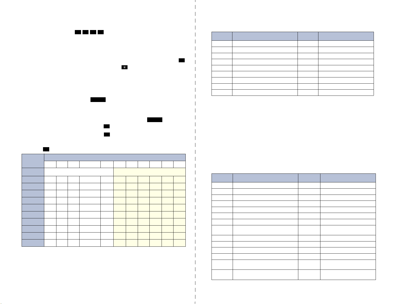
To Program System Speed-Dial Numbers:
— While on-hook, enter .
9
— Enter the speed dial location code (000-999) or (0000-4999).
— To change or program the name: Enter the desired name for the speed-dial
number using one of the following methods:
In numeric mode, the dialpad buttons are used to enter numbers 0-9, the
button is used for entering a hyphen, and the button is used for entering a
colon.
In alphanumeric mode, dialpad buttons are used to enter the desired letters,
numbers, and punctuation. The number of times a button is pressed determines which character is entered. When adjoining characters are located
under the same button, press to advance to the next character. Refer
to the following chart to program information in alphanumeric mode. (Note
that letters correspond to the letters printed on the dialpad buttons.)
To erase the current name and leave it blank: Press repeatedly
until the name is erased. Then press .
To leave the name the same: Press .
— Enter the number (up to 48 digits) to be stored.
—Press .
BUTTON 1 2 3 4 5 6 7 8 9 10 11
*The Japanese characters are only available if the multilingual feature is enabled and Japanese is installed as the secondary language.
**The character available depends on the software version.
#
NUMBER OF TIMES BUTTON IS PRESSED
ENGLISH CHARACTERS
1 -&( ) 1A I U E O a
2 ABC ' 2KA KI KU KE KO i
3 DEF ! 3SA SHI SU SE SO u
4 GHI * 4TA CHI TSU TE TO e
5 JKL
6 MNO
7 PQR S 7MA MI MU ME MO ya
8 TUV ? 8YA YU YO . , yu
9 WXY Z 9RA RI RU RE RO yo
0 @: . , 0WA WO N pa ba long
0
8
# or /**
Ñ or #**
1
#
FWD
MUTE
#
#
JAPANESE CHARACTERS*
5 NA NI NU NE NO o
6 HA HI FU HE HO tsu
Default Administrator Feature Codes
CODE
(US/EU)
9823 Automatic Diagnostics Delivery On/Off 9866 Modem Enable
9851 Clear Network Alarm 9869 Modem Reset
9850 Clear System Alarm 9860 Night Ring On/Off
9982/9182 Compression On/Off 9825 Periodic Diagnostics On/Off
9981/9181 Compression Statistics 9932/9132 Program Database
9900/9100 Diagnostics On/Off 9801 Program System Speed Dial
9862 Enable Network Day 9810 Set Network Date/Time
9861 Enable Network Night 9800 Set Time/Date
9867 Modem Disable 9811 Synchronize Network Time
FEATURE NAME CODE
(US/EU)
FEATURE NAME
System Diagnostics Features
System diagnostics mode allows a system administrator to perform diagnostics
functions such as freezing/unfreezing the database, printing message logs, and
seizing a device for troubleshooting purposes. Use diagnostics mode when the
system is idle to avoid affecting system performance.
To Enable/Disable System Diagnostics Mode:
While on-hook, enter the Diagnostics Mode feature code (9900 or 9100) to
enable/disable diagnostics mode. The display shows DIAGNOSTICS ON/OFF.
Then enter one of the following diagnostics feature codes (9xxx).
Default Diagnostics Feature Codes
CODE
(US/EU)
9926/9126 Diagnostic - ASAI Snoop Off 9963/9163 Diagnostic - Network Groups
9927/9127 Diagnostic - ASAI Snoop On 9972/9172 Diagnostic - Print Auxdata
9922/9122 Diagnostic - Dump Extension 9975/9175 Diagnostic - Print Message Log
9936/9136 Diagnostic - Dump Node Information 9976/9176 Diagnostic - Print Network Log
9933/9133 Diagnostic - Dump System Diagnostics 9978/9178 Diagnostic - Query Node Traffic
9943/9143 Diagnostic - Heap Dump 9928/9128 Diagnostic - Show Version
9947/9147 Diagnostic - Heap Statistics 9987/9187 Diagnostic - SIP View
9948/9148 Diagnostic - ISDN View 9910-9912/
9962/9162 Diagnostic - Major Reset 9974/9174 Diagnostic - System History
9945/9145 Diagnostic - Mark as Leaks 9983/9183 Diagnostic - View Displays
9946/9146 Diagnostic - Mark as Quiescent 9973/9173 Seize Device
9964/9164 Diagnostic - Minor Reset 9993/9133 System History Freeze
9939/9139 Diagnostic: Network Freeze Zone –
9989/9189 Diagnostic - Network Unfreeze Zone –
System Histories
System Histories
FEATURE NAME CODE
(US/EU
9110-9112
9998/9198 System History Unfreeze
FEATURE NAME
Diagnostic - Spare 1-3
Page 5

CS-5200/5400
Part Number
580.8001
COMMUNICATION SERVERS
ADMINISTRATOR GUIDE
ISSUE 1.1, August 2005
©Inter-Tel, Inc., August 2005, printed in the USA
Page 6

Page 7

NOTICE
This Inter-Tel® CS-5200/5400 Communication Servers Administrator Guide is released by Inter-Tel, Inc.
as a guide for system and voice mail administrators. It provides information necessary to properly
administer the system.
The contents of this guide, which reflect current Inter-Tel standards, are subject to revision or change
without notice. Some features or applications mentioned may require a future release and are not available in the initial release. Future product features and applications are subject to availability and cost.
Some features or applications may require additional hardware and/or specific software. Software packages released after the publication of this guide will be documented in addenda to the guide or succeeding issues of the guide.
For sales, service, or technical support, contact your local authorized Inter-Tel reseller.
If you have any questions or comments regarding this guide or other technical documentation, contact
the Inter-Tel Technical Publications Department at: Tech_Pubs@inter-tel.com.
All products and services mentioned in this publication are the trademarks, service marks, registered marks, or registered service
marks of their respective owners.
®
Inter-Tel
IBM
Microsoft
AudioCodes™ is a trademark of AudioCodes Ltd.
, Axxess®, Enterprise® Messaging, and Unified Communicator® are registered trademarks of Inter-Tel, Incorporated.
®
is a registered trademark of International Business Machines Corporation.
®
Windows® and ActiveSync® are a registered trademarks of Microsoft Corporation.
Page 8

Page 9

Contents
®
INTER-TEL
CS-5200/5400 ADMINISTRATOR GUIDE, ISSUE 1.1 – August 2005
Contents
CONTENTS PAGE
FCC Regulations ix
Safety Regulations xii
Network Security Statement xiv
Document Overview 1
Introduction . . . . . . . . . . . . . . . . . . . . . . . . . . . . . . . . . . . . . . . . . . . . . . . . . . . . . . . . . . . . . . 2
“Endpoints” and “Phones”. . . . . . . . . . . . . . . . . . . . . . . . . . . . . . . . . . . . . . . . . . . . . . . . . . 2
Changes to Issue 1.1. . . . . . . . . . . . . . . . . . . . . . . . . . . . . . . . . . . . . . . . . . . . . . . . . . . . . . . . 3
Intended Audience. . . . . . . . . . . . . . . . . . . . . . . . . . . . . . . . . . . . . . . . . . . . . . . . . . . . . . . . . 3
Sections of the Administrator Guide . . . . . . . . . . . . . . . . . . . . . . . . . . . . . . . . . . . . . . . . . . 4
Multicultural English References. . . . . . . . . . . . . . . . . . . . . . . . . . . . . . . . . . . . . . . . . . . . . 5
Document Navigation Aids . . . . . . . . . . . . . . . . . . . . . . . . . . . . . . . . . . . . . . . . . . . . . . . . . . 5
Inter-Tel Reference Documents . . . . . . . . . . . . . . . . . . . . . . . . . . . . . . . . . . . . . . . . . . . . . . 6
Hazard Identification and Supplemental Information . . . . . . . . . . . . . . . . . . . . . . . . . . . 7
Abbreviations and Acronyms. . . . . . . . . . . . . . . . . . . . . . . . . . . . . . . . . . . . . . . . . . . . . . . . 8
Product Description 1 1
Introduction . . . . . . . . . . . . . . . . . . . . . . . . . . . . . . . . . . . . . . . . . . . . . . . . . . . . . . . . . . . . . 12
Summary of Hardware and Software Features . . . . . . . . . . . . . . . . . . . . . . . . . . . . . . . . 13
Licensing. . . . . . . . . . . . . . . . . . . . . . . . . . . . . . . . . . . . . . . . . . . . . . . . . . . . . . . . . . . . . . . . 14
USB Security Key . . . . . . . . . . . . . . . . . . . . . . . . . . . . . . . . . . . . . . . . . . . . . . . . . . . . . . . . 14
Inter-Tel CS-5200. . . . . . . . . . . . . . . . . . . . . . . . . . . . . . . . . . . . . . . . . . . . . . . . . . . . . . . . . 15
Inter-Tel CS-5400. . . . . . . . . . . . . . . . . . . . . . . . . . . . . . . . . . . . . . . . . . . . . . . . . . . . . . . . . 15
Digital Expansion Interface . . . . . . . . . . . . . . . . . . . . . . . . . . . . . . . . . . . . . . . . . . . . . . . . 15
System Capacities . . . . . . . . . . . . . . . . . . . . . . . . . . . . . . . . . . . . . . . . . . . . . . . . . . . . . . . . 15
System Network Capacities . . . . . . . . . . . . . . . . . . . . . . . . . . . . . . . . . . . . . . . . . . . . . . . . 16
Voice Processing Systems . . . . . . . . . . . . . . . . . . . . . . . . . . . . . . . . . . . . . . . . . . . . . . . . . . 16
Voice Processing System Applications. . . . . . . . . . . . . . . . . . . . . . . . . . . . . . . . . . . . . . . . 17
Voice Mail Networking . . . . . . . . . . . . . . . . . . . . . . . . . . . . . . . . . . . . . . . . . . . . . . . . . . . . 20
Page v
Page 10

Contents
®
INTER-TEL
CS-5200/5400 ADMINISTRATOR GUIDE, ISSUE 1.1 – August 2005
CONTENTS PAGE
Administrator Procedures 21
Introduction . . . . . . . . . . . . . . . . . . . . . . . . . . . . . . . . . . . . . . . . . . . . . . . . . . . . . . . . . . . . . 22
System Administrator Procedures. . . . . . . . . . . . . . . . . . . . . . . . . . . . . . . . . . . . . . . . . . . 23
Voice Mail Administrator Procedures. . . . . . . . . . . . . . . . . . . . . . . . . . . . . . . . . . . . . . . . 57
Administrator Programming Planning Sheets . . . . . . . . . . . . . . . . . . . . . . . . . . . . . . . . . 69
Hardware and Endpoints 75
Introduction . . . . . . . . . . . . . . . . . . . . . . . . . . . . . . . . . . . . . . . . . . . . . . . . . . . . . . . . . . . . . 77
Inter-Tel CS-5200/5400 Communication Servers Chassis . . . . . . . . . . . . . . . . . . . . . . . . 77
Chassis Interfaces/Connections . . . . . . . . . . . . . . . . . . . . . . . . . . . . . . . . . . . . . . . . . . . . . 77
Modules. . . . . . . . . . . . . . . . . . . . . . . . . . . . . . . . . . . . . . . . . . . . . . . . . . . . . . . . . . . . . . . . . 79
IP Operating Modes . . . . . . . . . . . . . . . . . . . . . . . . . . . . . . . . . . . . . . . . . . . . . . . . . . . . . . 79
IP Endpoints. . . . . . . . . . . . . . . . . . . . . . . . . . . . . . . . . . . . . . . . . . . . . . . . . . . . . . . . . . . . . 81
ITP and SIP Connectivity. . . . . . . . . . . . . . . . . . . . . . . . . . . . . . . . . . . . . . . . . . . . . . . . . . 90
Features Common to IP and Digital Inter-Tel Endpoints . . . . . . . . . . . . . . . . . . . . . . . . 93
Digital Endpoints. . . . . . . . . . . . . . . . . . . . . . . . . . . . . . . . . . . . . . . . . . . . . . . . . . . . . . . . 101
Single Line Endpoints . . . . . . . . . . . . . . . . . . . . . . . . . . . . . . . . . . . . . . . . . . . . . . . . . . . . 106
Optional System Equipment. . . . . . . . . . . . . . . . . . . . . . . . . . . . . . . . . . . . . . . . . . . . . . . 108
Additional Information and Troubleshooting. . . . . . . . . . . . . . . . . . . . . . . . . . . . . . . . . 109
System Features 111
Introduction . . . . . . . . . . . . . . . . . . . . . . . . . . . . . . . . . . . . . . . . . . . . . . . . . . . . . . . . . . . . 117
Access to the Features . . . . . . . . . . . . . . . . . . . . . . . . . . . . . . . . . . . . . . . . . . . . . . . . . . . . 117
Attendant Phones. . . . . . . . . . . . . . . . . . . . . . . . . . . . . . . . . . . . . . . . . . . . . . . . . . . . . . . . 132
Hunt Groups. . . . . . . . . . . . . . . . . . . . . . . . . . . . . . . . . . . . . . . . . . . . . . . . . . . . . . . . . . . . 134
Trunk Features. . . . . . . . . . . . . . . . . . . . . . . . . . . . . . . . . . . . . . . . . . . . . . . . . . . . . . . . . . 152
Inter-Tel Endpoint Features . . . . . . . . . . . . . . . . . . . . . . . . . . . . . . . . . . . . . . . . . . . . . . . 166
Multilingual Capability. . . . . . . . . . . . . . . . . . . . . . . . . . . . . . . . . . . . . . . . . . . . . . . . . . . 172
Intercom Calls . . . . . . . . . . . . . . . . . . . . . . . . . . . . . . . . . . . . . . . . . . . . . . . . . . . . . . . . . . 175
Station-to-Station Messages . . . . . . . . . . . . . . . . . . . . . . . . . . . . . . . . . . . . . . . . . . . . . . . 180
Off-Hook Voice Announce (OHVA) . . . . . . . . . . . . . . . . . . . . . . . . . . . . . . . . . . . . . . . . . 184
Outside Calls . . . . . . . . . . . . . . . . . . . . . . . . . . . . . . . . . . . . . . . . . . . . . . . . . . . . . . . . . . . 186
Placing Calls On Hold. . . . . . . . . . . . . . . . . . . . . . . . . . . . . . . . . . . . . . . . . . . . . . . . . . . . 193
Call Waiting . . . . . . . . . . . . . . . . . . . . . . . . . . . . . . . . . . . . . . . . . . . . . . . . . . . . . . . . . . . . 196
Page vi
Page 11

Contents
®
INTER-TEL
CS-5200/5400 ADMINISTRATOR GUIDE, ISSUE 1.1 – August 2005
CONTENTS PAGE
System Features (Continued)
Call Transfer . . . . . . . . . . . . . . . . . . . . . . . . . . . . . . . . . . . . . . . . . . . . . . . . . . . . . . . . . . . 197
Call Screening . . . . . . . . . . . . . . . . . . . . . . . . . . . . . . . . . . . . . . . . . . . . . . . . . . . . . . . . . . 200
Reverse Transfer . . . . . . . . . . . . . . . . . . . . . . . . . . . . . . . . . . . . . . . . . . . . . . . . . . . . . . . . 201
Conference Calls . . . . . . . . . . . . . . . . . . . . . . . . . . . . . . . . . . . . . . . . . . . . . . . . . . . . . . . . 202
Record-A-Call . . . . . . . . . . . . . . . . . . . . . . . . . . . . . . . . . . . . . . . . . . . . . . . . . . . . . . . . . . 207
Agent Help . . . . . . . . . . . . . . . . . . . . . . . . . . . . . . . . . . . . . . . . . . . . . . . . . . . . . . . . . . . . . 208
System Forwarding . . . . . . . . . . . . . . . . . . . . . . . . . . . . . . . . . . . . . . . . . . . . . . . . . . . . . . 211
Call Forward . . . . . . . . . . . . . . . . . . . . . . . . . . . . . . . . . . . . . . . . . . . . . . . . . . . . . . . . . . . 217
Speed Dial. . . . . . . . . . . . . . . . . . . . . . . . . . . . . . . . . . . . . . . . . . . . . . . . . . . . . . . . . . . . . . 221
Intercom, Speed Dial, and Feature Code Directories. . . . . . . . . . . . . . . . . . . . . . . . . . . 227
House Phone. . . . . . . . . . . . . . . . . . . . . . . . . . . . . . . . . . . . . . . . . . . . . . . . . . . . . . . . . . . . 230
Redial . . . . . . . . . . . . . . . . . . . . . . . . . . . . . . . . . . . . . . . . . . . . . . . . . . . . . . . . . . . . . . . . . 231
Redirect Call. . . . . . . . . . . . . . . . . . . . . . . . . . . . . . . . . . . . . . . . . . . . . . . . . . . . . . . . . . . . 233
Paging . . . . . . . . . . . . . . . . . . . . . . . . . . . . . . . . . . . . . . . . . . . . . . . . . . . . . . . . . . . . . . . . . 234
Remove from Paging . . . . . . . . . . . . . . . . . . . . . . . . . . . . . . . . . . . . . . . . . . . . . . . . . . . . . 235
Do-Not-Disturb . . . . . . . . . . . . . . . . . . . . . . . . . . . . . . . . . . . . . . . . . . . . . . . . . . . . . . . . . 235
Do-Not-Disturb Override . . . . . . . . . . . . . . . . . . . . . . . . . . . . . . . . . . . . . . . . . . . . . . . . . 239
Remote Programming. . . . . . . . . . . . . . . . . . . . . . . . . . . . . . . . . . . . . . . . . . . . . . . . . . . . 239
Default Endpoint . . . . . . . . . . . . . . . . . . . . . . . . . . . . . . . . . . . . . . . . . . . . . . . . . . . . . . . . 242
Hookflash/Recall . . . . . . . . . . . . . . . . . . . . . . . . . . . . . . . . . . . . . . . . . . . . . . . . . . . . . . . . 243
Reminder Messages. . . . . . . . . . . . . . . . . . . . . . . . . . . . . . . . . . . . . . . . . . . . . . . . . . . . . . 244
Record Keeping and Maintenance Features. . . . . . . . . . . . . . . . . . . . . . . . . . . . . . . . . . 245
Audio Diagnostics . . . . . . . . . . . . . . . . . . . . . . . . . . . . . . . . . . . . . . . . . . . . . . . . . . . . . . . 252
Phantom Devices. . . . . . . . . . . . . . . . . . . . . . . . . . . . . . . . . . . . . . . . . . . . . . . . . . . . . . . . 255
Voice Processing Features 257
Introduction . . . . . . . . . . . . . . . . . . . . . . . . . . . . . . . . . . . . . . . . . . . . . . . . . . . . . . . . . . . . 259
Automated Attendant . . . . . . . . . . . . . . . . . . . . . . . . . . . . . . . . . . . . . . . . . . . . . . . . . . . . 259
Automatic Fax Detection. . . . . . . . . . . . . . . . . . . . . . . . . . . . . . . . . . . . . . . . . . . . . . . . . . 263
Automatic Speech Recognition. . . . . . . . . . . . . . . . . . . . . . . . . . . . . . . . . . . . . . . . . . . . . 264
Call Routing Announcement . . . . . . . . . . . . . . . . . . . . . . . . . . . . . . . . . . . . . . . . . . . . . . 265
Page vii
Page 12

Contents
®
INTER-TEL
CS-5200/5400 ADMINISTRATOR GUIDE, ISSUE 1.1 – August 2005
CONTENTS PAGE
Voice Processing Features (Continued)
Directories . . . . . . . . . . . . . . . . . . . . . . . . . . . . . . . . . . . . . . . . . . . . . . . . . . . . . . . . . . . . . 268
EM Directories. . . . . . . . . . . . . . . . . . . . . . . . . . . . . . . . . . . . . . . . . . . . . . . . . . . . . . . . . . 271
E-mail Reader . . . . . . . . . . . . . . . . . . . . . . . . . . . . . . . . . . . . . . . . . . . . . . . . . . . . . . . . . . 274
Fax-On-Demand . . . . . . . . . . . . . . . . . . . . . . . . . . . . . . . . . . . . . . . . . . . . . . . . . . . . . . . . 274
Record-A-Call . . . . . . . . . . . . . . . . . . . . . . . . . . . . . . . . . . . . . . . . . . . . . . . . . . . . . . . . . . 276
Scheduled Time-based Application Routing (STAR). . . . . . . . . . . . . . . . . . . . . . . . . . . 277
Voice Mail. . . . . . . . . . . . . . . . . . . . . . . . . . . . . . . . . . . . . . . . . . . . . . . . . . . . . . . . . . . . . . 279
Subscriber Features. . . . . . . . . . . . . . . . . . . . . . . . . . . . . . . . . . . . . . . . . . . . . . . . . . . . . . 284
Unified Messaging . . . . . . . . . . . . . . . . . . . . . . . . . . . . . . . . . . . . . . . . . . . . . . . . . . . . . . . 284
Voice Processing Prompts 293
Default Voice Processing Prompts . . . . . . . . . . . . . . . . . . . . . . . . . . . . . . . . . . . . . . . . . . 294
Default Feature Codes 357
Index 359
Page viii
Page 13

®
INTER-TEL
CS-5200/5400 ADMINISTRATOR GUIDE, ISSUE 1.1 – August 2005
FCC Regulations
IMPORTANT
1. This equipment complies with Part 68 of Federal Communications Commission (FCC)
rules. On the side of the equipment chassis is a label that contains, among other information, the FCC registration number and ringer equivalence number (REN) for this
equipment. Customers connecting this equipment to the telephone network shal l, before
such connection is made, give notice to the telephone company of the particular line(s)
to which such connection is to be made, and shall provide the telephone company with
the following information:
• Complies with Part 68 of the FCC Rules
• FCC registration number:
FCC Regulations
• USOC numbers of required interface jacks (see chart on next page)
• Service order code (SOC), as applicable (see chart on next page)
• Facility interface code (FIC) (see chart on next page)
• REN, as applicable (see chart on next page)
The REN is used to determine the number of devices that can be connected
to a single telephone line so that all the devices will ring or otherwise respond
to incoming calls. Each device that can be connected to a telephone line has
NOTE
The telephone company should also be given notice upon final disconnection of this
equipment from the particular line(s).
It is also the responsibility of the customer to provide the telephone company with registration numbers of any other devices which are configured for connection to the telephone network.
2. This equipmen t cannot be used on public coin service provided by the telephone com-
pany. Connection to party line service is subject to state tariffs. (Contact the state public
utility commission, public service commission, or corporation commission for information.)
a REN value. When the sum of device RENs on a line exceeds the maximum
REN value the line can support, usually 5.0, some or all of the devices may
not ring or respond appropriately. To identify the REN for lines in a telephone
service area, contact the telephone company.
3. If this eq uipment causes harm to the telephone network, the telephone company will
notify the customer in advance that service may be temporarily discontinued. But if
advance notice is not practical, the telephone company will notify the customer as soon
as possible. Also, the customer will be advised of the right to file a complaint with the
FCC, if necessary.
Page ix
Page 14

FCC Regulations
®
INTER-TEL
CS-5200/5400 ADMINISTRATOR GUIDE, ISSUE 1.1 – August 2005
4. The telephon e company may make changes in its facilities, equipment, operations, or
procedures which may affect the operation of this equipment. If so, the customer shall
be given advance notice so that any necessary modifications can be made in order to
maintain uninterrupted service.
5. If trouble is exp erienced with this equipment, contact a local authorized factory service
representative for repairs and/or warranty information. The customer, users, and unauthorized technicians should not repair, make adjustments to, or attempt to service this
equipment in any way.
6. In the event of trouble with the telephone line(s), this equipment must be disconnected
from the telephone line(s). If trouble ceases, the equipment must be repaired by an
authorized factory service representative. If the trouble continues to occur with the
equipment disconnected, the telephone company should be notified that they have a
problem. If this is the case, repairs or adjustments made by the telephone company will
be made at their expense.
7. Allowing this equipment to be operated in such a manner as to not provide proper
answer supervision signaling is in violation of Part 68 of FCC rules. This equipment
returns answer supervision signals to the public telephone network when: answered by
the called station, answered by the attendant, routed to a recorded announcement that
can be administered by the equipment user, and/or routed to a dial prompt. This equipment also returns answer supervision on all DID calls forwarded back to the public telephone network. Permissible exceptions are: a call is unanswered, busy tone is received,
or reorder tone is received.
8. This equipment is capable of providing users access to interstate providers of operator
services through the use of equal access codes. Failure to provide equal access capabilities is a violation of the Telephone Operator Consumer Services Improvement Act of
1990 and Part 68 of the FCC Rules.
TYPE OF PORT-
INTERFACE
2-Wire Loop 02LS2 –
D4 Superframe/AMI 04DU9-BN – 6.0Y RJ-48C
D4 Superframe with
B8ZS
Extended Super
frame (ESF)
ESF with B8ZS 04DU9-1SN – 6.0Y RJ-48C
Primary Rate ISDN 04DU9-1SN – 6.0Y RJ-48C
FACILITY INTER-
FACE CODE (FIC)
04DU9-DN – 6.0Y RJ-48C
04DU9-1KN – 6.0Y RJ-48C
RINGER EQUIVA-
LENCE NO. (REN)
SERVICE ORDER
CODE (SOC)
USOC JACK
CONNECTOR
Page x
Page 15

FCC Regulations
®
INTER-TEL
CS-5200/5400 ADMINISTRATOR GUIDE, ISSUE 1.1 – August 2005
NOTICE
The telephone instruments specifically designed for this system have hearing aid-compatible
handsets that are in compliance with section 68.316 of the FCC Rules.
The IP SLA complies with UL60950/CSA60950 and EN 60950 standards and complies with
EN 55022 and CFR 47 part 15 of the FCC Rules.
This equipment generates and uses radio frequency (RF) energy and if not installed and used
properly, that is, in strict accordance with the manufacturer ’s instructions, may cause interference to radio and television reception. It has been type tested and found to comply with the
limits for a Class A computing device in accordance with the specifications in Subpart J of Part
15 of FCC Rules. Operation of this equipment in a residential area may cause unacceptable
interference to radio and TV reception requiring the operator to take whatever steps are necessary to correct the interference. However, there is no guarantee that interference will not o ccur
in a particular installation. If this equipment does cause interference to radio or television
reception, which can be determined by turning the equipment off and on, the user is encouraged to try to correct the interference by one or more of the following measures:
• Reorient the receiving antenna.
• Relocate the equipment chassis with respect to the receiver.
• Check that the equipment chassis and receiver are not on the same circuit; the equip-
ment must be powered from an isolated, dedicated AC ou tlet.
• If necessary, the user should consult the dealer or an experienced radio/television technician for additional suggestions. The user may find the following booklet prepared by
the FCC helpful: “How to Identify and Resolve Radio-TV Interference Problems.”
This booklet is available from the U.S. Government Printing Office, Washington, D.C.
20402, Stock No. 004-000-00398-5.
If radio frequency interference (RFI) problems persist, contact Inter-Tel Customer Support.
The is now product safety certified by Canadian Standards Association (CSA) for use in
both the United States and Canada.
Page xi
Page 16

Safety Regulations
®
INTER-TEL
CS-5200/5400 ADMINISTRATOR GUIDE, ISSUE 1.1 – August 2005
Safety Regulations
IMPORTANT SAFETY INSTRUCTIONS
NOTICE
The “C US” indicator adjacent to the Ca nadian Standards Association (CSA) mark on the
product label signifies that the system has been evaluated to the applicable ANSI/UL and
CSA Standards for use in both the United States and Canada. The CSA is a Nationall y Recognized Testing Laboratory (NRTL). NRTL is a designation granted by the U.S. Occupational Health and Safety Administration (OSHA) to laboratories which have been accredited
to certify products to U.S. Standards.
Before installation, check the local electrical codes for important information concerning the
installation of telephone and electronic equipment.
The following safety information is reprinted from UL 1459. When using your telephone
equipment, basic safety precautions should always be followed to reduce the risk of fire, electric shock, and injury to persons.
1. Read and understand all instructions.
2. Follow all warnings and instructions marked on the product.
3. Unplug this product from the wall outlet before cleaning. Do not use liquid cleaners or
aerosol cleaners. Use a damp cloth for cleaning.
4. Do not use this product near water (for example, in a wet basement).
5. Do not place this product on an unstable cart, stand, or table. The product may fall,
causing serious damage to the product.
6. Slots and openings in the ch assis and the back or bott om are provided for v entilation, to
protect it from overheating; these openings must not be blocked or covered. This product should never be placed near or over a radiator or heat register. This product should
not be placed in a built-in installation unless proper ventilation is provided.
7. This product sh ould be operated only from the type of power source indicated in the
manual. If you are not sure of the type of power source to your building, consult your
dealer or local power company.
8. This product is equipp ed with a three-wire grounding type plug, a plug having a third
(grounding) pin. This plug will only fit into a grounding type power outlet. This is a
safety feature. If you are unable to insert the plug into the outlet, contact your electrician to replace your obsolete outlet. Do not defeat the safety purpose of the grounding
type plug.
Page xii
9. Do not all ow anything to rest on the power cord. Do not locate this product where the
cord will be abused by persons walking on it.
10. Do not use an ext ension cord wit h this product’s AC power cord. The AC outlet for this
product should not be used for any other electrical equipment.
Page 17
Safety Regulations
®
INTER-TEL
11. Never push objects of any kind into this product through chassis slots as they may touch
dangerous voltage points or short out parts that could result in a risk of fire or electric
shock. Never spill liquid of any kind on the product.
12. To reduce the risk of electric shock, do not disassemble this product, but take it to a
qualified serviceman when some service or repair work is required. Opening or removing covers may expose you to dangerous voltages or other risks. Incorrect reassembly
can cause electric shock when the product is subsequently used.
13. Unplug this product from the wa ll outlet and refer servicing to qualified service person-
nel under the following conditions:
• When the power supply cord or plug is damaged or frayed.
• If liquid has been spilled into the product.
• If the product has been exposed to rain or water.
• If the product does not operate normally by following the operating in structions.
CS-5200/5400 ADMINISTRATOR GUIDE, ISSUE 1.1 – August 2005
Adjust only those controls that are covered by the operating instructions because
improper adjustment of other controls may result in damage and will often require
extensive work by a qualified technician to restore the product to normal operation.
• If the product has been dropped or the chassis has been damaged.
• If the product exhibits a distinct change in performance.
14. Avoid using a telephone (other than a cordless type) during an electrical storm. There
may be a remote risk of electric shock from lightning.
15. Do not use the telephone to report a gas leak in the vicinity of the leak.
SAVE THESE INSTRUCTIONS
An exclamation point within a triangle, such as the one silk-screened on the
front of the equipment cabinet, or chassis, is intended to alert the user to a hazard that may result in bodily harm. To promote safe operation, maintenance,
!
Be sure to read and follow all of the instructions included in this manual and other applicable
literature.
and servicing of equipment, pay attention to the hazards identified in the literature accompanying the product.
NOTICE
NOTICE
The equipment contains no operator access areas and is certified only for installation in a
restricted access location, by trained personnel only. (UL 60950-1)
Page xiii
Page 18

Network Security Statement
®
INTER-TEL
CS-5200/5400 ADMINISTRATOR GUIDE, ISSUE 1.1 – August 2005
Network Security Statement
Although no telecommunications system or data network is entirely secure, as long as appropriate security measures are put in place and properly maintained by both the customer and the
installing company, this architecture and its associated server-based applications are substantially secure against unauthorized access to the customer's data network via the telecommunications system. Appropriate security measures include, but are not limited to, the proper
implementation of user/administrative accounts, passwords, firewalls, Network Address Translation (NAT), access control lists, virus protection, security updates, etc., and the proper maintenance of access points/programs and their respective accounts/passwords.
Page xiv
Page 19

Document Overview
®
INTER-TEL
CS-5200/5400 ADMINISTRATOR GUIDE, ISSUE 1.1 – August 2005
Document Overview
CONTENTS PAGE
Introduction. . . . . . . . . . . . . . . . . . . . . . . . . . . . . . . . . . . . . . . . . . . . . . . . . . . . . . . . . . . . . . . . . . 2
“Endpoints” and “Phones” . . . . . . . . . . . . . . . . . . . . . . . . . . . . . . . . . . . . . . . . . . . . . . . . . . . . . 2
Computer Science Roots . . . . . . . . . . . . . . . . . . . . . . . . . . . . . . . . . . . . . . . . . . . . . . . . . . . . . 2
Usage in This Manual . . . . . . . . . . . . . . . . . . . . . . . . . . . . . . . . . . . . . . . . . . . . . . . . . . . . . . . 2
Changes to Issue 1.1 . . . . . . . . . . . . . . . . . . . . . . . . . . . . . . . . . . . . . . . . . . . . . . . . . . . . . . . . . . . 3
Intended Audience . . . . . . . . . . . . . . . . . . . . . . . . . . . . . . . . . . . . . . . . . . . . . . . . . . . . . . . . . . . . 3
System Administrator . . . . . . . . . . . . . . . . . . . . . . . . . . . . . . . . . . . . . . . . . . . . . . . . . . . . . . . 3
Voice Mail Administrator . . . . . . . . . . . . . . . . . . . . . . . . . . . . . . . . . . . . . . . . . . . . . . . . . . . . 4
Sections of the Administrator Guide. . . . . . . . . . . . . . . . . . . . . . . . . . . . . . . . . . . . . . . . . . . . . . 4
Multicultural English References . . . . . . . . . . . . . . . . . . . . . . . . . . . . . . . . . . . . . . . . . . . . . . . . 5
Document Navigation Aids . . . . . . . . . . . . . . . . . . . . . . . . . . . . . . . . . . . . . . . . . . . . . . . . . . . . . 5
Paper . . . . . . . . . . . . . . . . . . . . . . . . . . . . . . . . . . . . . . . . . . . . . . . . . . . . . . . . . . . . . . . . . . . . 5
Electronic PDF. . . . . . . . . . . . . . . . . . . . . . . . . . . . . . . . . . . . . . . . . . . . . . . . . . . . . . . . . . . . . 5
Header and Footer Guides. . . . . . . . . . . . . . . . . . . . . . . . . . . . . . . . . . . . . . . . . . . . . . . . . . . . 6
Inter-Tel Reference Documents . . . . . . . . . . . . . . . . . . . . . . . . . . . . . . . . . . . . . . . . . . . . . . . . . . 6
Equipment Manuals. . . . . . . . . . . . . . . . . . . . . . . . . . . . . . . . . . . . . . . . . . . . . . . . . . . . . . . . . 6
Planning Sheets . . . . . . . . . . . . . . . . . . . . . . . . . . . . . . . . . . . . . . . . . . . . . . . . . . . . . . . . . . . . 6
Phone User Guides . . . . . . . . . . . . . . . . . . . . . . . . . . . . . . . . . . . . . . . . . . . . . . . . . . . . . . . . . 6
Hazard Identification and Supplemental Information . . . . . . . . . . . . . . . . . . . . . . . . . . . . . . . 7
Hazard Identification Methods . . . . . . . . . . . . . . . . . . . . . . . . . . . . . . . . . . . . . . . . . . . . . . . . 7
WARNING . . . . . . . . . . . . . . . . . . . . . . . . . . . . . . . . . . . . . . . . . . . . . . . . . . . . . . . . . . . . 7
CAUTION with Triangle . . . . . . . . . . . . . . . . . . . . . . . . . . . . . . . . . . . . . . . . . . . . . . . . . 7
CAUTION without Triangle . . . . . . . . . . . . . . . . . . . . . . . . . . . . . . . . . . . . . . . . . . . . . . 7
Supplemental Information. . . . . . . . . . . . . . . . . . . . . . . . . . . . . . . . . . . . . . . . . . . . . . . . . . . . 8
Abbreviations and Acronyms . . . . . . . . . . . . . . . . . . . . . . . . . . . . . . . . . . . . . . . . . . . . . . . . . . . 8
Page 1
Page 20

Document Overview
®
INTER-TEL
CS-5200/5400 ADMINISTRATOR GUIDE, ISSUE 1.1 – August 2005
Introduction
The Inter-Tel CS-5200/5400 Communication Servers Administrator Guide contains informa-
tion that System Administrators and Voice Mail Administrators need to know about the InterTel 5000 Network Com munications So lutions family of p roducts. The guide focuses o n syst em
hardware and software features and on the use of System Administrator and Voice Mail
Administrator phone features to perform typical adm inistrator tasks and activities. In structions
for using non-Administrator phones and the features other endpoints appear in the user guides
that come with those devices.
This section describes the guide’s content and organization, the intended audience, typographical conventions used to identify safety hazards and important information, related Inter-Tel,
Inc. technical documents, and a list of abbreviations used in the guide.
“Endpoints” and “Phones”
As digital, wireless, and computerized communication methods have evolved, the language of
telecommunications has had to change to keep pace. Not long ago, voice and modem-encoded
text were communicated from one telephone instrument to another across a global network of
copper wire, optical fiber, microwave antennas, and satellites. More recently, however, the
development of the Internet and of World Wide Web (www) sites have introduced a multimedia dimension to information and made it all more readily accessible through computer networking. As this evolution has occurred, new words and meanings have been introduced to
describe the new methods and equipment used for communicating.
Telephone systems that once provided only phone service to consumers have becom e “communication platforms” that support many devices that people can use for personal and business
communication. Phones now share communciation space with personal digital assistants
(PDA), with wireless phones capable of text messaging, taking photos, and recording video,
with fax machines that transmit and receive messages across Internet Protocol (IP), and with
“soft” phones that are displayed and used from computer screens.
Computer Science Roots
When referring to communication protocols in computer science, the term “endpoint”
describes an entity on one end of a Transport Layer connection. The Transport Layer is the
Transmission Control Protocol/Internet Protocol (TCP/IP) layer in the Open Systems Interconnect (OSI) network model. Utilizing the TCP/IP layer standard, Internet servers send and
receive packets of data across the World Wide Web.
Usage in This Manual
This manual uses the term “endpoint” to describe the entire category of devices that the InterTel 5000 family of products supports. In this context, digital and IP phones are endpoints, as
are data modules, fax machines, computer telephony (CT) gateways, Single-Line Adapters
(SLA), IP Single-Line Adapters (IP-SLA), and answering machines.
And, to promote clear communication and understanding, commonly accepted names of endpoints are used as appropriate. In particular, desktop IP endpoints are also referred to as IP
phones. Digital endpoints are also referred to as digital phones. Wireless endpoints are also
referred to as wireless phones. And, analog single line endpoints are also referred to as single
line phones or single line sets.
In the manual and in Database (DB) Programming, a phone may a lso be called a
NOTE
“station” when reference to the phone and its environment are intended. Or, it may
be called “device” in the most general sense.
Page 2 Computer Science Roots
Page 21

INTER-TEL
Changes to Issue 1.1
In addition to the content of Issue 1.0 of the Inter-Tel CS-5200/5400 Communication Servers
Administrator Guide, Issue 1.1 contains new information and related instr uctions, and id enti-
fied errors have been corrected.
Information and related instructions abou t the following hardware and software fe atures have
been added:
• Digital Expansion Interface (DEI) equipment
• Digital Endpoint Module (DEM-16)
• Digital phones
• Single-Line Adapters (SLA), each of which supports two single line analog phones, or
• Four-trunk Loop Start Module (LSM-4)
• Basic Rate Module (BRM-S) that supports Basic Rate Interface (BRI) trunk capabilities
• Modem Data Port Module (MDPM)
• Personal Computer Data Port Module (PCDPM)
• Network Address Translation (NAT) traversal
®
CS-5200/5400 ADMINISTRATOR GUIDE, ISSUE 1.1 – August 2005
analog endpoints such as fax machines or recording machines
Document Overview
• Off-Hook Voice Announce
Intended Audience
This guide provides information and procedures for carrying out typical System Administrator
and Voice Mail Administrator tasks.
System Administrator
System Administrators typically perform the following tasks:
• Place the local system or other systems in the network in night or day mode
• Set the date and time of the local system
• Set the network date and time and resynchronize clocks in the network
• Make database changes, as described in “Programming the Database Using a System
• Program System Speed Dial numbers on the local system
• Receive and clear displayed system and network alarms
• Use diagnostic mode features to:
Any Inter-Tel phone can be designated as a System Administrator phone through Database
Programming. However, to facilitate programming and to manage alarm messages, Inter-Tel
recommends using a Model 8660 Six-Line Display IP phone or a Model 8560, Executive, or
Professional Six-Line Display digital phone for this purpose. System Administrator features
are described in detail beginning on page 23.
Administrator Phone’’ on page 26.
— Freeze and unfreeze database history on the local system or other systems in the
network.
— Print error logs.
— Seize specific devices for troubleshooting purposes.
— Report audio problems to your installer/technician.
System Administrator
Page 3
Page 22

Document Overview
®
INTER-TEL
CS-5200/5400 ADMINISTRATOR GUIDE, ISSUE 1.1 – August 2005
Voice Mail Administrator
Voice Mail Administrators can use special features that are not provided to other voice mail
users. The mailbox designated as the Administrator mailbox has all of the standard subscriber
features, which can be found in the appropriate user guide, plus the ability to perform th e following tasks:
• Record a broadcast message
• Perform mailbox and group list maintenance
• With Audiotex recordings, create and select customized voice mail company greetings,
Automated Attendant recordings, call routing announcements, and hunt group overflow and announcement station recordings
• Import fax documents
• Customize voice mail prompts
Voice Mail Administrator procedures are described on page 57.
Sections of the Administrator Guide
This Administrator Guide includes the following sections:
• Document Overview: This section provides information about the document’s struc-
ture and content, associated documents, typographical methods used to call the reader ’s
attention to important information, and a listing of selected abbreviations and acron yms
used throughout the document.
• Product Description: The Product Description section describes system processes,
capacity and feature summaries, and licensing requirements of the Inter-Tel CS-5200/
5400 platform. defines capacities, dimensions, and parameters of the hardware and software components of the systems. The section also identifies the environmental conditions required to ensure safe and reliable system operation.
For further details, turn to the section. Or, if viewing the PDF version of the manual, go
directly to the section by clicking Product Description.
• Administrator Procedures: This section provides procedures for performing typical
System Administrator and Voice Mail Administrator tasks and activities.
For further details, turn to the section. Or, if viewing the PDF version of the manual, go
directly to the section by clicking Administrator Procedures.
• Hardware and Endpoints: This section describes the physical equipment that makes
up the Inter-Tel 5000 Network Communications Solutions. Included are the Inter-Tel
CS-5200/5400 Communication Servers; the Digital Expansion Interface (DEI); processor, trunk, and endpoint modules; IP and digital phones; and other endpoints.
For further details, turn to the section. Or, if viewing the PDF version of the manual, go
directly to the section by clicking Hardware and Endpoints.
• System Features: The System Features section describes the business communication
features available to Inter-Tel 5000 users. The section identifies trunk and feature codes,
phone and endpoint features, system management and control features, and Administrator and Attendant features.
For further details, turn to the section. Or, if viewing the PDF version of the manual, go
directly to the section by clicking System Features.
Page 4 Voice Mail Administrator
Page 23

®
INTER-TEL
CS-5200/5400 ADMINISTRATOR GUIDE, ISSUE 1.1 – August 2005
• Voice Processing Features: The Voice Processing Features section describes Basic
Voice Mail features and optional external Voice Mail options.
For further details, turn to the section. Or, if viewing the PDF version of the manual, go
directly to the section by clicking Voice Processing Features.
For reference, the guide also provides a comprehensive list of Voice Processing Prompts to aid
in the development of custom messages and a table that summarizes Default Feature Codes.
Multicultural English References
This guide supports the requirements of administrators in the United States of America (US)
and in the Inter-Tel Europe market, which includes the United Kingdom (UK). Because of this
dual support, dual references are made to industry features, standards, and jargon, as appropriate throughout the guide. For the purposes of this guide, British English technical terms are
assumed to apply to other English-speaking European cultures, as well.
For example, the US telecom industry refers to a communication line between a public sw itching system and a private switching system as a “central office (CO) trunk.” In the UK, this
same type of line is called a “local exchange trunk.” Applying the dual-reference guideline
would result in the following statements:
• During system installation, t he technician connects CO trunks/local exchange trunks to
the LSM-2 modules
Document Overview
• To turn the Diagnostics Mode on or off at an Administrator phone, the System Administrator enters 9900 (9100 in Europe).
However, this guide does not make a similar distinction between American English and British
English spellings of common words. Only American English spellings appear in this guide. For
example, the word “analog” is not also spelled “analogue” since the meaning is clear .
NOTE
Document Navigation Aids
To help users know what section and topic they are looking at in the guide, each page contains
the identification in both paper and electronic formats.
Paper
A paper copy of this guide contains Contents pages showing the outline of the entire manual
and the page number where each section, heading, and subheading begins. For quick reference
to sections, the section title appears in a black box on the outside edge of each page of the section. Together, the black boxes form a visual aid that marks the extent of the pages in each section. Also at the beginning of the guide are a List of Figures and a List of Tables with page
locations. Each section also provides a Contents page or pages. To help the user locate specific
information in the manual, an Index of topics and subtopics appears at the end of the manual.
As appropriate for clarity and legibility, the British English variation of a term
may also appear in brackets or be written out. For instance, the first of the
preceding examples could read:
. . .CO trunks [local exchange trunks in Europe]. . . .
Electronic PDF
When viewing the Portable Document Format (PDF) version of this document, the user will
see blue hyperlinked references to other parts of the manual . To use a hyperlink, the user must
move the pointer over the blue hyperlink. When the pointer changes form, the user clicks to go
to the hyperlinked destination.
Voice Mail Administrator
Page 5
Page 24

Document Overview
®
INTER-TEL
CS-5200/5400 ADMINISTRATOR GUIDE, ISSUE 1.1 – August 2005
Header and Footer Guides
Whether using the electronic PDF or the paper version, users can identify the section of the
guide they are viewing by looking at the header or footer of the page. The first major document
topic on a page appears both in the header, next to the section title, and in the footer opposite th
page number.
Inter-Tel Reference Documents
The following documents provide detailed technical information about Inter-Tel CS-5200 and
Inter-Tel CS-5400 Communication Servers, peripheral equipment, phones, and other endpoints that are related to administrator activities.
Equipment Manuals
Technical details and equipment-specific procedures appear in the following documents:
• Enterprise
• Inter-Tel CS-5200/5400 Communication Servers Installation and Maintenance Manual,
part no. 580.8000
• v1.1 Addendum, Inter-Tel CS-5200/5400 Communication Servers Installation and
Maintenance Manual, Issue 1.0, part no. 580.8002
®
Messaging Installation Manual, part no. 780.8006
• Inter-Tel CS-5200/5400 Communication Server Administrator Guide & Administrator
• System Manager Installation and Maintenance Manual, part no. 835.2743
• Message Print Diagnostics Manual, part no.550.8018
• Voice Processing Diagnostics Manual, part no. 550.8019
• Voice Processing Unit Installation Manual, part no. 835.2890
Planning Sheets
The programming planning sheets that appear in this guide are included on the product CDROM, and they can be obtained in the following soft file format:
• Inter-Tel CS-5200/5400 Program Planning Sheets (.DOC), part no. 835.2882
Phone User Guides
Technical details and instructions for using the digital phones supported by the Inter-Tel 5000
appear in the following user guides:
• Model 8500 User Guide, part no. 550.8114
• Model 8520 User Guide, part no. 550.8112
• Model 8560 and 8660 User Guide, part no. 550.8 113
• Associate Display and Basi c Digit al Endpoint User Guide, part no. 560.8003
Quick Reference Guide, part no. 580.8001
• Executive Display and IP PhonePlus Endpoint User Guide, part no. 550.8108
• Standard Display and Basic Digital Endpoint User Guide, part no. 550.8109
• Professional Display and IP PhonePlus Endpoint User Guide, part no. 560.8002
• Single-Line Endpoint User & Quick Reference Guide, part no. 550.8107
Page 6 Inter-Tel Reference Documents
Page 25
®
INTER-TEL
CS-5200/5400 ADMINISTRATOR GUIDE, ISSUE 1.1 – August 2005
Hazard Identification and Supplemental Information
This guide uses standardized graphic conventions to promote safe practices, to prevent or minimize damage to equipment, to avoid the corruption of data, and to clarify the Inter-Tel, Inc.
position on certain technical or business issues.
Potentially harmful situations are identified in boxes labeled with internationally recognized
safety graphics according to the degree of hazard exposure. Typically, a technician is exposed
to all the identified hazards, while an administrator is exposed only to data corruption hazards.
In addition the identification of safety hazards, relevant Inter-Tel, Inc. policies, important information, and notes are set apart from the flow of the text in boxes with attention-getting labels.
This section explains the conventions used and their meanings.
Hazard Identification Methods
Three hazard identification methods appear in this manual, as described in the following paragraphs.
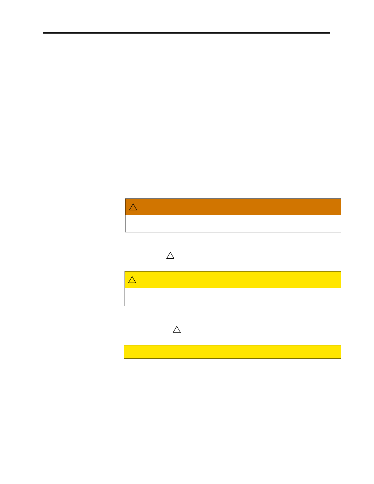
WARNING!
A WARNING identifies a hazard that, if not heeded, could cause definite personal injury.
Document Overview
WARNING
Possible electrical shock. Use the LCD panel to shut down the system, then turn
OFF the AC POWER before working on the external voice processing PC. . . .
CAUTION with Triangle
A CAUTION with the symbol identifies a hazard that, if not heeded, could cause minor
personal injury.
CAUTION
Possible pinch hazard. Keep fingers clear of the edges of the faceplate when
inserting a trunk module into the chassis. . . .
CAUTION without Triangle
A CAUTION without the symbol identifies a hazard that, if not heeded, could cause damage to equipment or corruption of data or databases.
CAUTION
Possible data corruption and/or equipment damage. Power down the system
before removing the Compact Flash . . . .
WARNING!
Page 7
Page 26
Document Overview
®
INTER-TEL
CS-5200/5400 ADMINISTRATOR GUIDE, ISSUE 1.1 – August 2005
Supplemental Information
Notices, Notes, and Important messages provide supplemental information about the topic
being discussed.
A NOTICE stipulates conditions, requirements, and/or policies relevant to the topic under discussion.
A NOTE conveys supplemental information related to the topic.
An IMPORTANT message contains information that requires special attention related to the
topic.
NOTICE
For correct operation of the system, use ONLY the compact flash memory cards
available through Inter-Tel, Inc.
NOTE Commercially available premoistened towels provide adequate cleaning.
IMPORTANT
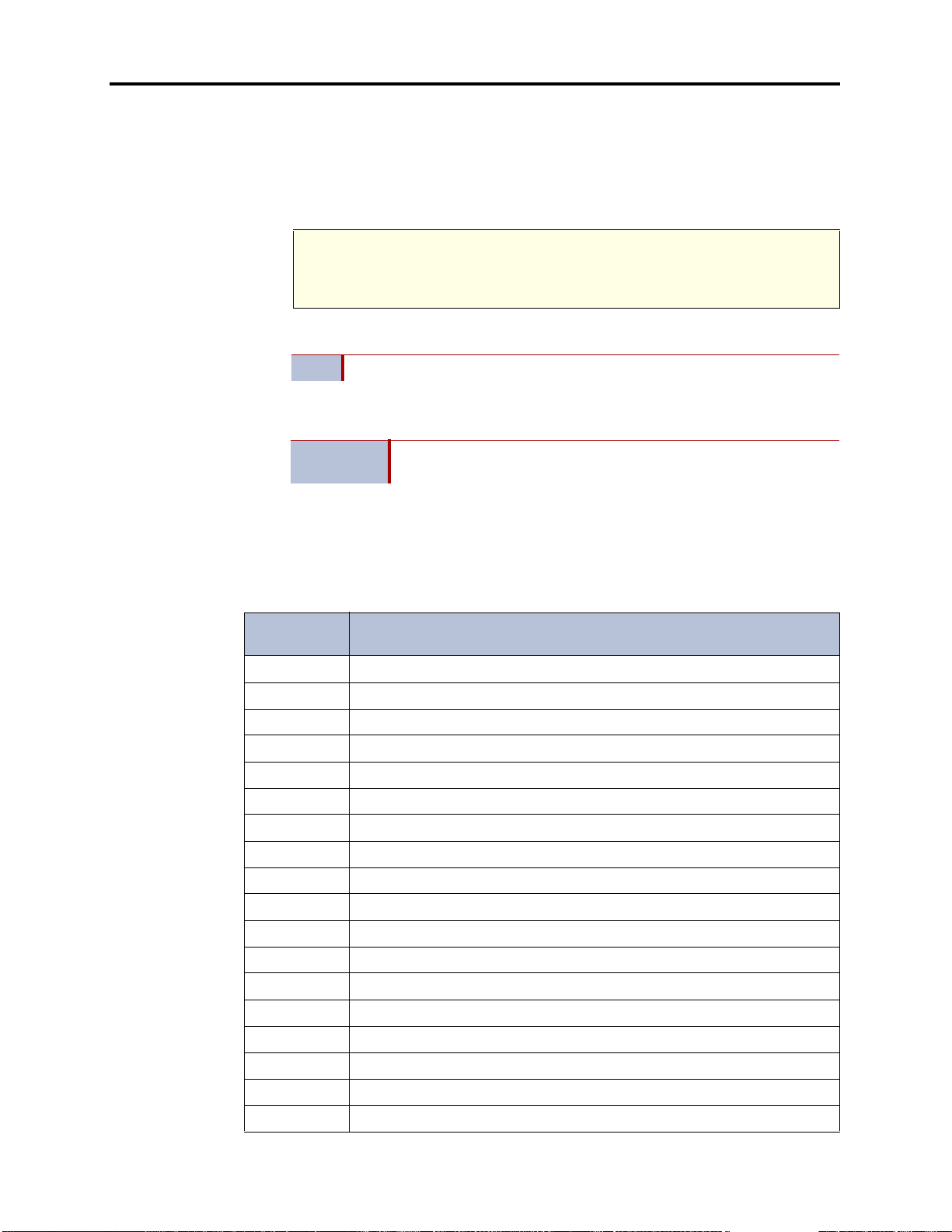
Abbreviations and Acronyms
In addition to industry-wide and/or i nternationa lly recognized units of measure, such as Hz, V,
AC, DC, A, ms, etc., the following abbreviations and acronyms appear in this document.
Table 1. Abbreviations and Acronyms
ABBREVIA-
TION
ACD Automatic Call Distribution
ADD Automatic Diagnostics Delivery
AMIS Audio Messaging Interchange Specification
ANI Automatic Number Identification
ANSI American National Standards Institute
ARM Asynchronous Response Mode
ARS Automatic Route Selection
ASAI Adjunct Switch Application Interface
AV DAP Advanced Voice Data Applications Processor
BLF Busy Lamp Field
BVM Basic Voice Mail
Make sure the chassis connects firmly to earth ground at the Ground
Lug.
SPELLED-OUT MEANING
CD Compact Disk
CF Compact Flash
CLID Calling Line IDentification (European/British)
CLIP Calling Line Identification Presentation (Caller ID/CLID for wireless)
CO Central Office
CP Call Processing
CPE Customer Provided Equipment
Page 8 CAUTION without Triangle
Page 27

®
INTER-TEL
CS-5200/5400 ADMINISTRATOR GUIDE, ISSUE 1.1 – August 2005
Table 1. Abbreviations and Acronyms (Continued)
ABBREVIA-
TION
CS Communication Server
CT Computer Telephony
DDI Direct Dialing Inward (DID in Europe)
DHCP Dynamic Host Configuration Protocol
DID Direct Inward Dialing
DISA Direct Inward System Access
DND Do-Not-Disturb
DNIS Dialed Number Identification Service
DSP Digital Signal Processor
DSS Direct Station Selection
E&M Ear and Mouth
®
EM Enterprise
EMI Electrom
ESD Electros
Messaging
agnetic Interference
tatic Discharge
SPELLED-OUT MEANING
Document Overview
FCC Federal Communications Commission
FoIP Fax over Internet Protocol
FTP File Transfer Protocol
GW Gateway
HTML Hypert
IP Internet Protocol
IPR IP Resource
IPRA IPR Application
ISDN Integrated Services Digital Network
ITP Inter-Tel Protocol
LAN Local Area Network
LCD Liquid Crystal Display
LED Light Emitting Diode
LSM Loop Start Module
MDF Main Distribution Frame
MGCP Media Gateway Control Protocol
MOH Music On Hold
MRA Material Return Authorization
NAT Network Address Translation
N/A Not Available or Not Applicable, as appropriate
ext Markup Language
OAI Open Architecture Interface
OPX Off Premises Ex
CAUTION without Triangle
tension
Page 9
Page 28

Document Overview
®
INTER-TEL
CS-5200/5400 ADMINISTRATOR GUIDE, ISSUE 1.1 – August 2005
Table 1. Abbreviations and Acronyms (Continued)
ABBREVIA-
TION
OSA Operator System Access
OSI Open Systems Interconnect
P2P Peer to Peer
PC Personal Computer
PCM Pulse Code Modulation
PDA Personal Digital Assistant
PDF Portable Document Format
PEC Processor Expansion Card
PPP Point-to-Point Protocol
PRI Primary Rate Interface
PSTN Public Switched Telephone Network
QoS Quality of Service
REN Ringer Equivalence Number
RFI Radio Frequency Interference
SPELLED-OUT MEANING
RJ Registered Jack
RMS Root Mean Square
RTCP Real-time Transport Control Protocol
RTP Real-time Transport Protocol
SSH Secure SHell
SIP Se s sion Initiation Protocol
SLA Single-Line Adapter
SMDR Station Message Detail Recording
TCP Transmission Control Protocol
TDM Time Division Multiplex
TFTP Trivial File Transfer Protocol
UCD Uniform Call Distribution
UDP User Datagram Protocol
UK United King dom
US United States of America
USB Universal Serial Bus
VAD Voice Activity Detection
VoIP Voice over Internet Protocol
VPU Voice Processing Unit
WAN Wide Area Network
Page 10 CAUTION without Triangle
Page 29

Product Description
®
INTER-TEL
CS-5200/5400 ADMINISTRATOR GUIDE, ISSUE 1.1 – August 2005
Product Description
CONTENTS PAGE
Introduction . . . . . . . . . . . . . . . . . . . . . . . . . . . . . . . . . . . . . . . . . . . . . . . . . . . . . . . . . . . . . 12
Inter-Tel CS-5200/5400 Communication Servers . . . . . . . . . . . . . . . . . . . . . . . . . . . . . 12
Inter-Tel Network Capability . . . . . . . . . . . . . . . . . . . . . . . . . . . . . . . . . . . . . . . . . . . . . 12
IP Resources. . . . . . . . . . . . . . . . . . . . . . . . . . . . . . . . . . . . . . . . . . . . . . . . . . . . . . . . . . 13
Internet Protocol Resource Application . . . . . . . . . . . . . . . . . . . . . . . . . . . . . . . . . . . . . 13
Inter-Tel 5000 IP Resource Usage . . . . . . . . . . . . . . . . . . . . . . . . . . . . . . . . . . . . . . . . . 13
Summary of Hardware and Software Features . . . . . . . . . . . . . . . . . . . . . . . . . . . . . . . . 13
Licensing. . . . . . . . . . . . . . . . . . . . . . . . . . . . . . . . . . . . . . . . . . . . . . . . . . . . . . . . . . . . . . . . 14
USB Security Key . . . . . . . . . . . . . . . . . . . . . . . . . . . . . . . . . . . . . . . . . . . . . . . . . . . . . . . . 14
Inter-Tel CS-5200. . . . . . . . . . . . . . . . . . . . . . . . . . . . . . . . . . . . . . . . . . . . . . . . . . . . . . . . . 15
Inter-Tel CS-5400. . . . . . . . . . . . . . . . . . . . . . . . . . . . . . . . . . . . . . . . . . . . . . . . . . . . . . . . . 15
Digital Expansion Interface . . . . . . . . . . . . . . . . . . . . . . . . . . . . . . . . . . . . . . . . . . . . . . . . 15
System Capacities . . . . . . . . . . . . . . . . . . . . . . . . . . . . . . . . . . . . . . . . . . . . . . . . . . . . . . . . 15
System Network Capacities . . . . . . . . . . . . . . . . . . . . . . . . . . . . . . . . . . . . . . . . . . . . . . . . 17
Voice Processing Systems . . . . . . . . . . . . . . . . . . . . . . . . . . . . . . . . . . . . . . . . . . . . . . . . . . 17
Basic Voice Mail . . . . . . . . . . . . . . . . . . . . . . . . . . . . . . . . . . . . . . . . . . . . . . . . . . . . . . 17
Enterprise Messaging . . . . . . . . . . . . . . . . . . . . . . . . . . . . . . . . . . . . . . . . . . . . . . . . . . . 18
Voice Processing Unit. . . . . . . . . . . . . . . . . . . . . . . . . . . . . . . . . . . . . . . . . . . . . . . . . . . 18
Voice Processing System Applications. . . . . . . . . . . . . . . . . . . . . . . . . . . . . . . . . . . . . . . . 18
Voice Mail Networking . . . . . . . . . . . . . . . . . . . . . . . . . . . . . . . . . . . . . . . . . . . . . . . . . . . . 21
Page 11
Page 30

Product Description
®
INTER-TEL
CS-5200/5400 ADMINISTRATOR GUIDE, ISSUE 1.1 – August 2005
Introduction
The Inter-Tel 5000 Networ k Communicati ons Solutions pl atform is a converged communications platform designed for use in small- and medium-sized business environments. It provides
an Internet Protocol (IP) solution for telecommunication needs and supports IP phones, InterTel digital phones, standard single line pho nes, and ot her endpoints.
The system provides call processing and business productivity features, messaging services
with Basic Voice Mail (BVM) and Fax over IP (FoIP), Wide Area Network (WAN) Fail Survivability, and a Power Fail Bypass relay. On the main chassis of the platform, the Inter-Tel
CS-5200/5400 Communication Servers, are ports for connecting two loop start trunks, two single line endpoints, external voice mail, Music On Hold (MOH), and Paging.
Inter-Tel CS-5200/5400 Communication Servers
The Inter-Tel CS-5200/5400 Communication Servers furnish th e processing power and the
integration hardware and circuits for the Inter-Tel 5000 Network Communications Solutions
platform. The communication servers function identically, but the Inter-Tel CS-5200 provides
fewer IP resources than the Inter-Tel CS-5400. For an explanation of IP resources, refer to “IP
Resources,” which follows on this page.
In this guide, a “trunk” is an audio path that connects the Inter-Tel 5000 with the public telephone network. Both systems can support between 2 and 92 non-IP trunks. In addition, the CS5200 is capable of supporting 28 IP gateway trunks, IP network trunks, or IP endpoints, and
the CS-5400 is capable of supporting 116 IP gateway trunks, IP network trunks, or IP endpoints.
System capacities cited in this guide refer to the maximum number possible before
NOTE
making resource tradeoffs. The actual number of trunks or endpoints installed on a
system depends on the user’s requirements and the physical constraints and configuration of the system.
BVM is provided with the system, but o increase voice mail capacity BVM can be replaced
with either a Vo ice Processing Unit (VPU) or an Enterprise® Messaging (EM) system. For
details, refer to “Voice Processing Features” on page 257
Digital signal processors (DSP) enable Conferencing, Dual Tone Multi-Frequency (DTMF)
detection, tone generation, modem operati on, and Automatic Number Identification (ANI).
ANI is the technical term for Caller ID.
Inter-Tel Network Capability
Two or more Inter-Tel advanced communication platforms, Axxess or Inter-Tel 5000, can be
connected with T1/E1/PRI network spans to form a network. To the user, the network appears
as one integrated system. With few exceptions, the user can perform all of the functions across
the network that can be performed within a single system, or node.
In an Inter-Tel IP private network environment, IP endpoints can be programmed to traverse,
or bypass, the Network Address Translation (NAT) tables. The Inter-Tel 5000 may be placed
behind the firewall using a static NAT assignment. For details, contact you Inter-Tel equipment
provider.
Either communication server can operate as a stand-alone system or as a node in a network of
up to 63 Inter-Tel Axxess or Inter-Tel 5000 nodes. For network connectivity, Inter-Tel Axxess
Converged Communications Platforms require software v7.0 or later for T1 point-to-point protocol (PPP) networking. IP networking requires v8.231 or later system software, IP Resources
Card (IPRC) firmware v9.0.0 or later, and applicable licensing.
.
®
Page 12 Introduction
Page 31

®
INTER-TEL
CS-5200/5400 ADMINISTRATOR GUIDE, ISSUE 1.1 – August 2005
IP Resources
This guide refers frequently to the term “IP resources,” which has an important meaning in
computer telephony (CT) jargon. In common English usage, the word “resources” refers to a
supply that can be drawn on when n eeded. Com puting resources constitute the needed supply
to run CT applications, and different applications require different amounts of resources. The
supply of computing resources that is not actually in use is available to run applications.
A “resource” might be understood as an abstract way to describe the amount of computing
capability that voice processing software and hardware need to work together. Resources are
used to describe an interface of a physical device used for call processing, such as a phone, as
seen by a software application. Examples of such interfaces include a fax processing resource,
voice recognition resource, or text-to-speech resource.
The communication server installed—Inter-Tel CS-5200 or CS-5400—determines the amount
of IP resources the Inter-Tel 5000 can supply to support voice processing tasks.
Internet Protocol Resource Application
The Internet Protocol Resource Application (IPRA) supplies IP functionality for the system
and communicates to the IP phones, IP trunk gateways, and other IP endpoints across 10/
100Base-T Ethernet.
Product Description
Inter-Tel 5000 IP Resource Usage
On the Inter-Tel 5000, IP resources are used to provide the following call processing capabilities:
• IP endpoints
• IP network connections
• Faxing between Inter-Tel 5000 nodes
The correct allocation of IP resources is an important factor in maintaining a system th at functions without calls being blocked. System Administrators can promote nonblocking system
performance by making sure that the allocation of system IP resources is appropriate for their
needs. System Administrators having questio ns or concerns about the all ocation of system IP
resources should contact their Inter-Tel equipment and service provider.
Summary of Hardware and Software Features
Built on 32-bit architecture and packaged in a space-efficient 1¾-inch (4.45 cm)-high 1U chassis, the Inter-Tel CS-5200/5400 provides a robust IP com munication solutio n. With appropriate
licensing, the Inter-Tel CS-5200/5400 delivers communication assets that include the following
hardware and features:
• Linux
• Connectivity for Loop Start, T1, T1/Primary Rate Interface (PRI), E1/PRI, and IP gate-
®
operating system
way (MCGP and SIP) trunks, and for trunk-only capability of Basic Rate Interface
(BRI)
• Basic Voice Mail
• Unified Messaging
• Networking over IP
• Networking over T1/E1 spans
• Fax over IP (FoIP)—T.38—Inter-Tel 5000 to Inter-Tel 5000 nodes only
Summary of Hardware and Software Features
Page 13
Page 32

Product Description
®
INTER-TEL
CS-5200/5400 ADMINISTRATOR GUIDE, ISSUE 1.1 – August 2005
• CompactFlash memory card for storing system applications, customer database, and
voice mail messages
• USB flash drive (thumb drive) for backing up voice mail prompts and messages
• Support for IP, SIP, Multi-Protocol, Wireless IP, Multimedia Touch Screen, digital, and
single line hard phones, and for one PDA soft phone
• Support for nonphone endpoints such as IP gateway trunks, IP SLAs, SLAs, fax
machines, and answering machines
• Programmable Call Processing features (Refer to “System Features” on page 111)
• Directory Look-Up
• Hunt Groups
• Automatic Call Distribut ion
• Uniform Call Distribution
• Open Architecture Interface (OAI)
• Multilingual Support
• Music-On-Hold
Licensing
The Inter-Tel CS-5200 is the basic system. In the default configuration, it comes with five IP
endpoint licenses and three IP networking resources. With required hardware and licensing, the
Inter-Tel CS-5200 can support a mix of up to 28 IP endpoints, IP network trunks, and/or IP
gateway trunks. Additional IP endpoint licenses are required before more than five IP end points will operate on a system.
The Inter-Tel CS-5400 is an Inter-Tel CS-5200 with a Processor Expansion Card (PEC-1) and
licensing added to the system. In the default configuration, it comes with five IP endpoint
licenses and six IP networking resources. With required hardware and licensing, the Inter-Tel
CS-5400 can support a mix of up to 116 IP endpoints, IP network trunks, and/or IP gateway
trunks.
Each of the DEIs is licensed separately, as are premium features. For lists of standard and premium features refer to “System Features” on page 111.
USB Security Key
The USB security key uniquely identifies a system by storing an Inter-Tel Master License.
Only the specific software license that has been digitally signed with the Master License data is
allowed to control the system. The key stores the essential components of the software licensing scheme.
• Paging
• Power Fail Bypass circuitry
• Wide Area Network (WAN) Fail Survivability
The security key also ensures licensing integrity. When a system detects removal of its key, the
system disables audio for subsequent calls. When the audio is disabled, the system posts applicable alarms to the LCD panel on the front of the unit chassis and to the LCD on the Administrator endpoint. Alarm #122 indicates that the key is missing, while Alarm #125 identifies the
number of minutes before the system initiates a reset.
Page 14 Licensing
Page 33

When the key is replaced and the correct serial number is detected by the system, the audio is
enabled and the reset countdown is aborted.
If the system powers up without the USB security key in place, the user must reload the software license through database programming.
Inter-Tel CS-5200
For smaller user environments, the Inter-Tel CS-5200 default configuration includes the Processor Module (PM-1), five IP endpoint licenses, three IP networking resources, and the CompactFlash, USB, and equipment interface ports on the chassis. If the three IP networking
resources are used, sufficient IP resources are available for installing 25 IP endpoints. All told,
with required interface hardware and licensing the Inter-Tel CS-5200 supports a mix of up to
28 IP endpoints, IP private networking trunks, and/or IP gateway trunks.
For system configuration, programming, and installation details, c ontact your authorized InterTel equipment provider.
Inter-Tel CS-5400
Adding a Processor Expansion Card (PEC-1) to the PM-1 and applicable licensing to the base
platform creates the Inter-Tel CS-5400. The default configuration of the larger-capacity system
includes six IP networking resources in addition to the five IP endpoint licenses and platform
interface ports on the chassis. If the six IP networking resources are used, sufficient IP
resources are available for installating 110 IP endpoints. With required interface hardware and
licensing, the Inter-Tel CS-5400 supports a mix of up to 116 IP endpoints, IP network trunks,
and/or IP gateway trunks.
INTER-TEL
Product Description
®
CS-5200/5400 ADMINISTRATOR GUIDE, ISSUE 1.1 – August 2005
Digital Expansion Interface
To provide Inter-Tel digital phone capability, one or two Digital Expansion Interface (DEI)
units can be added to the system c hassis. Each DEI provides three bays that acc ept Digital
Endpoint Modules (DEM-16). Each DEM-16 supports 16 digital Inter-Tel phones or SingleLine Adapters (SLA), providing for connection of up to 48 Inter-Tel digital phones or SLAs.
Each SLA supports one or two single line analog phones.
In addition to IP endpoints, each licensed DEI connected to the Inter-Tel CS-5200 chassis provides capability to add up to three Digital Endpoint Modules (DEM-16) that would support up
to 48 digital endpoints.
For each digital phone substituted with a Single-Line Adapter (SLA), two single line phones
can be added to the system.
System Capacities
The Inter-Tel CS-5200/5400 chassis supports:
• Central Office (CO)/Local Exchange Trunks: Including the two loop start circuits
built into the chassis, up to 14 loop start trunks can be supported by the Inter-Tel 5000.
Up to three Loop Start Modules (LSM) can be installed, and LSMs are available with
either two or four ports.
• T1/E1/PRI Spans: Up to three T1 , T1/PRI, or E1/PRI spans can be connected to the
Inter-Tel CS-5200/5400 chassis through T1/E1/PRI modules. Each module supports one
span. A T1 span supports up to 24 trunks; a T1/PRI span supports up to 23 trunks; and,
an E1/PRI span supports up to 30 trunks. Trunk options in DB Programming include
Loop Start, Off-Premises Extension (OPX), Direct Inward Dial (DID) [Direct Dialing
Inward (DDI), in Europe], T1, T1/PRI, E1/PRI, and T1/E&M .
• Endpoints: The Inter-Tel CS-5200/5400 supports Inter-Tel IP phones and other IP end-
points, IP and SIP trunk gateways, Inter-Tel digital phones and other digital endpoints,
Inter-Tel CS-5200
Page 15
Page 34

Product Description
®
INTER-TEL
CS-5200/5400 ADMINISTRATOR GUIDE, ISSUE 1.1 – August 2005
IP Single-Line Adapters (IP-SLA), Single-Line Adapters (SLA), and single line analog
phones and other endpoints.
• Pocket PC SoftPhone: The Model 8601 is a SIP softphone that runs on selected Pocket
PC 2002 (or later) Personal Digital Assistant (PDA) platforms. The IPRA supports the
Model 8601 Pocket PC SIP-mode softphone, which is described in the following paragraph, but does not support Inter-Tel legacy IP SoftPhones.
• Multi-protocol phones: A multi-protocol phone is o ne that operates either in Inter-Tel
Protocol (ITP) mode or in Session Initiation Protocol (SIP) mode. A SIP server is
required for SIP mode operation. Multi-protocol phones include Models 8620/86 22,
8662, and 8690. Multi-protocol phones require software licenses.
• Wireless phones: Models 8664, 8665, and 8668 are wireless phones that operate in ITP
mode.
• Single line phones: In addition being able to install single line phones in each of the
two circuits built into the Inter-Tel CS-5200/5400 chassis, one single line phone can be
installed in with each IP-SLA, and two single line phones can be installed with each
SLA.
System Network Capacities
Two or more Inter-Tel Advanced Communications Platforms (Inter-Tel 5000 or Axxess) can be
connected to form a network that provides a seamless interface between the systems. To the
user, the network appears as one integrated system. With few exceptions, the user can perform
all of the functions across the network that can be performed within a single system.
In this guide, all references to a “network” mean two or more connected systems. Each system
in a network is called a “node.”
The maximum capacities for networking appear in Table 2.
* The maximum number of endpoints an d trunks that can be in stalled is lim ited by the n umber
of voice channels and/or system memory resources available.
Voice Processing Systems
Inter-Tel CS-5200/5400 Communication Servers support an internal Inter-Tel 5000 voice processing system, Basic Voice Mail (BVM), and two external voice processing systems, the
Voice Processing Unit (VPU) and Enterprise Messaging (EM).
Table 2.
System Nodes per network 63
Local devices per node 304*
Off-node devices per node 10,000
Devices per network 40,000
System Network Capacities
FEATURE/DEVICES CAPACITY
Basic Voice Mail
Basic Voice Mail (BVM) is built into Inter-Tel 5000 platform capability to provide voice mail
and messaging services. BVM does not support Fax-On-Demand or Unified Messaging.
BVM messages are stored on a CompactFlash (CF) memory card form atted by Inter-Tel. The
card also stores system applications and the user database.
Page 16 System Network Capacities
Page 35

Product Description
®
INTER-TEL
CS-5200/5400 ADMINISTRATOR GUIDE, ISSUE 1.1 – August 2005
The data capacity of the CF determines the amount of BVM message storage, which ranges
from 30 hours with a 256 MB card to more than 211 hours with a 1 GB card. For storage of
voice mail messages and greetings, custom prompts, and Record-A-Call messages, each system CF reserves a predetermined amount of memory. The larger the capacity of the CF, the
more memory will be available for storage, as shown in Table 3.
The amount of message storage, which is allocated for each user as a quota of the total storage
capacity, is programmable in minutes through DB Programming. A warning flag can be set for
each mailbox to alert the user when a specified percentage of the allocated quota has been
reached.
In addition to the standard US English prompts, each set of language prompts reduces by
approximately 75 minutes the amount of storage available for allocation. Table 3 shows the
amount of message storage available on the three sizes of CF before additional sets of prompts
are applied. In addition to US English, the system supports UK English, Spanish, and Japanese
language prompts.
Table 3.
When all of the IP resources available for BVM are busy, the next callers are camped-on to
wait for a resource to become available. Upgrading to an expanded, external voice mail system
is recommended when an unacceptable number of callers are being camped-on before they can
leave a voice message.
BVM can be replaced with an external Voice Processing Unit (VPU) or Enterprise® Messaging (EM) system. The VPU and EM systems can be installed on any or all nodes in the network to allow a caller to leave a message on a local voice processing system for a mailbox
located on another voice processing system in the network.
Enterprise Messaging
Enterprise Messaging (EM) is an optional external system that unifies communication and
messaging by providing access to voice mail, fax, and e-mail messages in the user’s mailbox.
In addition, EM provides automatic speech recognition capabilities and built-in Unified Messaging features. EM runs on the Windows 2000 operating system. For detailed information
about EM, refer to the Enterprise Messaging Installation Manual, part no. 780.8006.
BVM Storage Capacities on CompactFlash Memory Cards
Compact Flash Card
256 MB with US English prompts 30 hr (1800 min)
512 MB with US English prompts 90 hr (5420 min)
1024 MB with US English prompts 211 hr (12,670 min)
Basic Voice Mail
Storage Capacity
Voice Processing Unit
The Voice Processing Unit (VPU) is an optional external system that provides integrated voice
processing. Integrated features include Voice Mail, Automated Attendant, Hunt Group
announcement and overflow, optional Fax-On-Demand, buffered SMDR, Record-A-Call, and
others. , with special applications software that can be attached to the telephone system. VPU
runs on either the Windows NT or Windows 2000 operating systems. For detailed information
about EM, refer to the Voice Processing Unit Installation Manual, part no. 835.2890.
Voice Processing System Applications
Inter-Tel voice processing systems support several voice processing system applications.
Depending on your site’s voice processing system, equipment, and licensing, you may have
access to one or more of the following voice processing system features:
Voice Processing System Applications
Page 17
Page 36

Product Description
®
INTER-TEL
CS-5200/5400 ADMINISTRATOR GUIDE, ISSUE 1.1 – August 2005
• Automated At tendant: Automated Attendant is a programmable feature that provides
automated call answering service s. Calls can transfer, forward, or directly ring in to
Automated Attendant. When Autom ated Attendant answers a call, it plays a recording
that gives dialing instructions. After hearing the recording, or at any time while it is
playing, the caller may dial an extension or mailbox number. For information about the
Automated Attendant feature, refer to page 259.
• Automated Att endant Recall Destination: If a call that is transferred by Automated
Attendant is not answered before the Transfer Voice Processor timer expires, the call
recalls the Automated Attendant Recall Destination. The Recall Destination announces
that the phone is unavailable and allows the caller to leave a message if the phone has
an associated mailbox, or to dial another extension. For information about the Automated Attendant Recall Destination, refer to page 260.
• Automatic Fax Detection: With Automatic Fax Detection, Call Routing Announce-
ment (CRA) applications and mailboxes can be programmed to automatically route
incoming fax calls to a specified extension or to an e-mail address. For information
about the Automatic Fax Detection, refer to page 263.
• Automatic Speech Recognition (ASR): The EM system supports Automatic Speech
Recognition (ASR). ASR can be enabled on many levels within the voice processing
system. Using EM, subscribers can issue spoken commands to navigate the voice mail
menus. Subscribers and nonsubscribers can also use spoken commands to search the
voice mail directory and to navigate Automated Attendant menus and CRA paths.
When ASR resources are not available, subscribers and nonsubscribers can also perform these tasks by pressing the appropriate dialpad digits when prompted by the sy stem. For information about ASR, refer to page 264.
• Call Routing Announcement (CRA): This application can be used in place of a play-
back device and is useful for programming Hunt Group announcement and overflow
stations. When called, the CRA application plays a recording and then hangs up.
The CRA application uses digit translation to help calling parties reach their intended
destinations. Digit translation allows the caller to press a single digit to access a mailbox, a Fax-on-Demand function, a station, or a Hunt Group. Digit translation can be
programmed for each digit from 0 through 9, #, and *, plus a Timeout option that
applies if the caller does not enter a digit when prompted. If programmed, each digit
could lead the caller to a “digit translation node” that has its own set of digit translation
values. This layered CRA digit translation creates a “tree” of programmable digit translation nodes. For more detailed information about CRA, refer to page 265.
• Directory Services: Directory Services provide callers with a list of mailboxes and
extension IDs that can be accessed through Voice Mail or the Automated Attendant.
The Directory feature is available in each of the voice processing systems, but varies
slightly in the EM system. For information about directories, refer to page 268. For
information about using directories in EM, refer to page 271.
• E-mail Reader: E-mail Reader is a licensable feature available with the EM voice pro-
cessing system. It provides users with advanced mailbox capabilities through Text-ToSpeech (TTS) technology. When E-mail Reader is enabled for a mailbox, users can
access voice mail, e-mail, and fax messages by logging in to their mailboxes. E-mail
Reader announces the message envelope and can also “read” the text in the body of email messages. E-mail Reader users also have access to additional message options,
which vary based on the media type. For information about E-mail Reader, refer to
page 274.
• Fax-On-Demand: The Fax-On-Demand feature is a speciall y programmed Call Rout-
ing Announcement application that uses digit translation to allow callers to select the
documents they want to have faxed to them. Callers can use a DTMF endpoint to
request one or more documents from the company’s fax library, the library that is al so
Page 18 Voice Processing System Applications
Page 37

Product Description
®
INTER-TEL
CS-5200/5400 ADMINISTRATOR GUIDE, ISSUE 1.1 – August 2005
used in the Unified Messaging faxing feature. When the request is completed, the voice
processing system places a call to the caller’s fax machine to deliver the requested documents. For information about Fax-On-Demand, refer to page 274.
• Record-A-Call: This feature allows a phone user to record a call-in-progress as a voice
mailbox message. When a phone user enters the Record-A-Call feature code, the system places a call to the phone’s assigned Record-A-Call application. When the application answers, the system sets up a conference call with the Record-A-Call mailbox. If
programmed, the mailbox plays a greeting to indicate that the recording is in progress.
For information about the Record-A-Call feature, refer to page 276.
• Scheduled Time-based Application Routing (STAR): STAR enhances the program-
mability of the voice mail application greetings. Applications can be programmed to
play alternative greetings for holidays and weekends. A STAR application is a table of
up to 20 entries that serves as a “routing table.” STAR tells the voice processing system
which application to use to respond to incoming calls. Based on day-and-time information defined in the table, the identified applications are programmed to play the greetings and STAR routes the call to the predetermined application. For information about
STAR, refer to page 277.
• Station Message Detail Recording (SMDR) Information Storage: SMDR informa-
tion is stored only on the VPU voice processing system hard disk, then proce ssed using
call record sorting software. BVM and EM do not support SMDR information storage.
• Voice Mail and Message Notification Retrieval: Other than messages that are sent
through the Message Notificati on/Retrieval application, Voice Mail handles all voice
mail calls directed to it. If your system is using EM and E-Mail Reader is enabled for
the mailbox, users have access to advanced messaging features using their advanced
mailbox. With Voice Mail, callers hear the main company greetin g, followed by a m enu
of available options. Message Notification/Retrieval provides voice mail message notification and quick mailbox access. For information about Voice Mail and Message
Notification Retrieval, refer to page 279.
• Unified Messaging: The Unified Messaging (UM) feature links the voice processing
system with e-mail and/or provides outgoing fax capabilities. Depending on which
voice processing system you are using, you may have UM version 2.2 or 2.3. For information about UM, refer to page 284.
Voice Processing System Applications
Page 19
Page 38

Product Description
®
INTER-TEL
CS-5200/5400 ADMINISTRATOR GUIDE, ISSUE 1.1 – August 2005
Voice Mail Networking
A voice processing system can be installed on any or all nodes in the user ’s network. These
voice processing systems can also be networked together to allow a caller to leave a message
on the local voice processing system for a mailbox located on another voice processing syst em
in the network.
Maximum capacities of networked voice processing systems are listed in Table 4.
Table 4.
Network Capacities
FEATURE/DEVICES CAPACITY
Voice Processing Systems per network
Local or Off-Node Mailboxes/Extension IDs per Voice Processing System
node
System Audio Interface Ports per node 40
Applications per node 150
Group Lists per node
Members per group list
Remote Message Notification Numbers per mailbox 18
Audiotex Recordings per node 500
Message Notification/Retrieval Applications per node 1
System Passwords per node 4
Time Slot Groups per node 10
a
This is the maximum number of nodes supported by the software. System traffic may limit
100
10,000
1000
1500
a
b
the actual number of nodes that can be supported without affecting system performance.
b
This is the maximum number of mailboxes supported by the NT-based software.
Page 20 Voice Mail Networking
Page 39

Administrator Procedures
®
INTER-TEL
CS-5200/5400 ADMINISTRATOR GUIDE, ISSUE 1.1 – August 2005
Administrator Procedures
CONTENTS PAGE
Introduction . . . . . . . . . . . . . . . . . . . . . . . . . . . . . . . . . . . . . . . . . . . . . . . . . . . . . . . . . . . . . 22
System Administrator Phone Designation . . . . . . . . . . . . . . . . . . . . . . . . . . . . . . . . . . . 22
Scheduled Delayed Major Resets. . . . . . . . . . . . . . . . . . . . . . . . . . . . . . . . . . . . . . . . . . 22
System Administrator Procedures. . . . . . . . . . . . . . . . . . . . . . . . . . . . . . . . . . . . . . . . . . . 23
Placing the Local System in Day or Night Mode. . . . . . . . . . . . . . . . . . . . . . . . . . . . . . 23
Placing Network Nodes in Day or Night Mode . . . . . . . . . . . . . . . . . . . . . . . . . . . . . . . 23
Setting System Date and Time . . . . . . . . . . . . . . . . . . . . . . . . . . . . . . . . . . . . . . . . . . . . 24
Setting Network Date and Time. . . . . . . . . . . . . . . . . . . . . . . . . . . . . . . . . . . . . . . . . . . 24
Synchronizing Network Time. . . . . . . . . . . . . . . . . . . . . . . . . . . . . . . . . . . . . . . . . . . . . 25
Programming the Database Using a System Administrator Phone . . . . . . . . . . . . . . . . 26
Station Programming. . . . . . . . . . . . . . . . . . . . . . . . . . . . . . . . . . . . . . . . . . . . . . . . 27
System Programming . . . . . . . . . . . . . . . . . . . . . . . . . . . . . . . . . . . . . . . . . . . . . . . 32
Trunk Programming . . . . . . . . . . . . . . . . . . . . . . . . . . . . . . . . . . . . . . . . . . . . . . . . 38
Programming System Speed Dial Numbers. . . . . . . . . . . . . . . . . . . . . . . . . . . . . . . . . . 45
Programming and Using Mini-DSS Buttons . . . . . . . . . . . . . . . . . . . . . . . . . . . . . . . . . 47
Managing System and Network Alarms. . . . . . . . . . . . . . . . . . . . . . . . . . . . . . . . . . . . . 49
System Alarms . . . . . . . . . . . . . . . . . . . . . . . . . . . . . . . . . . . . . . . . . . . . . . . . . . . . 49
Network Alarms . . . . . . . . . . . . . . . . . . . . . . . . . . . . . . . . . . . . . . . . . . . . . . . . . . . 49
Clearing Alarms . . . . . . . . . . . . . . . . . . . . . . . . . . . . . . . . . . . . . . . . . . . . . . . . . . . 52
Alarm Queue . . . . . . . . . . . . . . . . . . . . . . . . . . . . . . . . . . . . . . . . . . . . . . . . . . . . . . 52
Enabling/Disabling the Internal Modem . . . . . . . . . . . . . . . . . . . . . . . . . . . . . . . . . . . . 54
Resetting the Internal Modem . . . . . . . . . . . . . . . . . . . . . . . . . . . . . . . . . . . . . . . . . . . . 54
Using the Network Group Diagnostics Feature . . . . . . . . . . . . . . . . . . . . . . . . . . . . . . . 55
Seizing a Device. . . . . . . . . . . . . . . . . . . . . . . . . . . . . . . . . . . . . . . . . . . . . . . . . . . . . . . 55
Freezing/Unfreezing the System History . . . . . . . . . . . . . . . . . . . . . . . . . . . . . . . . . . . . 56
Freezing/Unfreezing the Network History. . . . . . . . . . . . . . . . . . . . . . . . . . . . . . . . . . . 56
Voice Mail Administrator Procedures. . . . . . . . . . . . . . . . . . . . . . . . . . . . . . . . . . . . . . . . 57
Recording a Broadcast Messages. . . . . . . . . . . . . . . . . . . . . . . . . . . . . . . . . . . . . . . . . . 58
Maintaining Mailboxes and Group Lists . . . . . . . . . . . . . . . . . . . . . . . . . . . . . . . . . . . . 58
Voice Mail Administrator Capabilities . . . . . . . . . . . . . . . . . . . . . . . . . . . . . . . . . . 58
Mailbox and Extension ID Personal Options . . . . . . . . . . . . . . . . . . . . . . . . . . . . . 59
Change Procedures for Mailbox Personal Options . . . . . . . . . . . . . . . . . . . . . . . . . 60
Changing A Group List Name . . . . . . . . . . . . . . . . . . . . . . . . . . . . . . . . . . . . . . . . 64
Importing Fax Documents . . . . . . . . . . . . . . . . . . . . . . . . . . . . . . . . . . . . . . . . . . . . . . . 64
Creating Audiotex Recordings . . . . . . . . . . . . . . . . . . . . . . . . . . . . . . . . . . . . . . . . . . . . 65
Recording Custom Voice Mail Prompts . . . . . . . . . . . . . . . . . . . . . . . . . . . . . . . . . . . . . 67
Administrator Programming Planning Sheets . . . . . . . . . . . . . . . . . . . . . . . . . . . . . . . . . 69
Page 21
Page 40

Administrator Procedures
®
INTER-TEL
CS-5200/5400 ADMINISTRATOR GUIDE, ISSUE 1.1 – August 2005
Introduction
When programming your site’s database, the Inter-Tel-certified technician can program a
phone’s extension as both a System Administrator and a Voice Mail Administrator. Sometimes
the two jobs are handled by the same person. You can use a phone that has been designated as
an Administrator phone to perform certain programming tasks for the call processing system
and/or the voice mail system. In addition, the System Administrator phone shows system and
network alarm messages.
This section provides you with the instructions for performing System Administrator and Voice
Mail Administrator tasks. The information is presented as follows:
• System Administrator Procedures begin on page 23.
• Voice Mail Administrator Procedures begin on page 57.
A Quick Reference Guide containing instructions for frequently performed procedures is
located in the front of this guide.
As a System Administrator, you must know which languages are considered Pri-
NOTE
System Administrator Phone Designation
mary and Secondary for the system. The platform supports American English,
British English, Spanish, and Japanese prompts and displays.
Any Inter-Tel phone can be designated as a System Adm inistrator phone through Database
Programming. However, to facilitate programming and to manage system Alarm messages,
Inter-Tel recommends using a six-line display phone for this purpose, such as the Model 8660
IP phone or Model 8560 digital phone.
NOTE A single line phone cannot be used as an Administrator phone.
If a user of a non-Administrator display phone attempts to execute Administrator features, the
user will hear fast-busy reorder tones, and the display will show CANNOT ACCESS
RESERVED FEATURE.
Scheduled Delayed Major Resets
A delayed major reset is sometimes needed when programming the database u sing the Administrator phone. If a major reset is required, the message, ENTER SYS RESET OPTION
appears on the phone display. You can select to perform an immediate major reset when this
message is shown, or you can schedule a delayed major reset. The delayed major reset option
allows you to schedule a reset to occur when the system is not in use.
The following programming changes do not require a major reset:
• Changing extensions
• Swapping extensions
• Creating off-node devi ces
• Changing ACD Agent IDs
• Adding and removing extensions from Extension Lists
• Equipping and unequipping devices
Page 22
Page 41

®
INTER-TEL
CS-5200/5400 ADMINISTRATOR GUIDE, ISSUE 1.1 – August 2005
System Administrator Procedures
With a System Administrator phone, you can perform the following procedures:
• Place the local node in night or day mode
• Place other network nodes in night or day mode
• Set the date and time of the local node
• Set the network date and time
• Synchronize clocks in the network
• Make database changes (see page 26 for a list of programming areas)
• Enable, disable, and reset local and off-node call processing application modems
• Program System Speed Dial numbers on the local node
• Receive and clear displayed system and network alarms
• Use diagnostic mode features:
— Freeze and unfreeze the database history for the local node or any node in the net-
work using programmed freeze zones
— Print error logs
— Seize specific devices for troubleshooting purposes
Administrator Procedures
Placing the Local System in Day or Night Mode
You can use a System Administrator phone to place the local node in day or night mode. The
day or night mode selects preprogrammed database lists to determine trunk access, toll restriction, emergency outgoing access, etc. for the phones in the system. Active calls are not affected
when the Day–Night mode is changed.
To view Day–Night Mode status:
While on-hook, enter the Night Ring On/Off feature code (9860). You hear a single confirmation tone. The display shows NIGHT MODE IS ON (or OFF). If night mode was turned on,
the display shows THE SYSTEM IS IN NIGHT MODE until day mode is turned on.
Placing Network Nodes in Day or Night Mode
You can use a System Administrator phone to place one or more nodes in day or night mode.
The day–night mode determines which lists the system will use for trunk access, toll restriction, etc.
The network determines the day/night mode status of a call based on the day/night mode status
of the node where the trunk resides.
To turn night mode on:
1. While on-hook, enter the Enable Network Night feature code (9861).
2. When prompted to enter a node number., enter 01–63 for the desired node number. To
select all nodes, enter 00.
You hear a single confirmation tone. The display shows NIGHT MODE IS ON. Then
the display shows NODE X IS IN NIGHT MODE until day mode is turned on.
To turn day mode on:
1. While on-hook, enter the Enable Network Day feature code (9862).
2. When you are prompted to enter a node number, enter the desired node number.
You hear a single confirmation tone. The display shows DAY MODE IS ON.
Placing the Local System in Day or Night Mode
Page 23
Page 42

Administrator Procedures
®
INTER-TEL
CS-5200/5400 ADMINISTRATOR GUIDE, ISSUE 1.1 – August 2005
Setting System Date and Time
NOTE
A System Administrator can manu ally reset the system time or date when it is necessary. For
example, when the system is defaulted or for daylight-saving time. Any Administrator can
change the date and time that appears on all display endpoints and in the SMDR rep orts. The
day of the week is automatically calculated and set by the system when the date is entered.
To set the system date and time:
Inter-Tel CS-5200/5400 supports the Automatic Daylight Saving Time (British
Summer Time, in Europe) feature. However, the Enable Daylight Saving Time
flag in Database Programming must be set to Yes to use the Automatic Daylight
Saving Time/British Summer Time feature.
NOTE
If necessary, press to backspace, or press or CANCEL to start over.
MUTE
1. While on-hook, enter the Set Date/Time feature code (9800). Your display shows DATE
<current date>.
2. If you do not need to change the date, press or
#
ACCEPT to skip to the TIME
XX:XX prompt.
3. Use the dialpad buttons to enter the month, day, and year. For example, press 020301
for February 3, 2001. When finished, the display shows TIME <current time>. If you
entered the date incorrectly, the display shows INVALID DATE, and you are prompted
to enter a new date.
NOTE
If you do not need to change the time, press or
If using a phone programmed for the Japanese language, enter the date
as year, month, day. For example, 050203 for February 3, 2005.
#
ACCEPT twice to exit. The display
shows SYSTEM DATE AND TIME UPDATED.
4. Use the dialpad buttons to enter the time in hours and minutes. For example, enter 0900
for 9:00. If you entered the time incorrectly, the display shows INVALID TIME and
you are prompted to enter a new time.
5. If the system is set for 12-hour display format, the display shows SELECT AM OR
PM (AM=1 PM=2). Press (or the
1 2
AM menu button) for AM or press (or the PM
menu button) for PM. The display shows SYSTEM DATE AND TIME UPDATED. If
you press any button other than 1 or 2, the display shows INVALID TIME and you are
prompted to enter a new time.
NOTE
If using a phone programmed for the Japanese language, the prompts will
be reversed and you will set the AM or PM before the hour and minutes.
Setting Network Date and Time
Occasionally, the network time or date needs to be reset, such as when the system is defaulted
or when daylight-saving time/British summer ti me is implemented. Any System Administrator
can change the date and time that appears on all display phones and that appears in the SMDR
reports in the network. The day of the week is automatically calculated and set by the system
when the date is entered.
Page 24 Placing Network Nodes in Day or Night Mode
Page 43

®
INTER-TEL
CS-5200/5400 ADMINISTRATOR GUIDE, ISSUE 1.1 – August 2005
To set the network date and time:
Administrator Procedures
NOTE
If you make a mistake, press to backspace or press or CANCEL to
leave it unchanged and start over.
MUTE
1. While on-hook, enter the Set Network Date and Time feature code (9810). Your display
shows DATE <current date>.
#
2. If you do not need to change the date, press or
ACCEPT to skip to the TIME
XX:XX prompt.
3. Use the dialpad buttons to enter the month, day, and year. For example, press 020301
for February 3, 2001. When finished, the display shows TIME <current time>.
NOTE
If using a phone programmed for the Japanese language, enter the date
as year, month, day. For example, 050203 for February 3, 2005.
If you entered the date incorrectly, the display shows INVALID DATE, and you are
prompted to enter a new date.
If you do not need to change the time, press or
#
ACCEPT twice to exit. The display
shows SYSTEM DATE AND TIME UPDATED.
4. Use the dialpad buttons to enter the time in hours and minutes. Fo r example, enter 0900
for 9:00.
NOTE
If using a phone programmed for Japanese, the prompts are reversed and
you will set the AM or PM before the hour and minutes.
If you entered the time incorrectly, the display shows INVALID TIME, and you are
prompted to enter a new time.
5. If the node is set for 12-hour display format, the display shows SELECT AM OR PM
(AM=1 PM=2). Press (or the
menu button) for PM. The display shows SYSTEM DATE AND TIME UPDATED. If
you press any button other than 1 or 2, the display shows INVALID TIME, and you are
prompted to enter a new time.
Synchronizing Network Time
System Administrators can synchronize the m inutes past the hour across the network with out
changing the hour. This is useful when the nodes are in different time zones.
If the node time is off by more than 30 minutes, synchronizing the minutes may
NOTE
To synchronize the clocks in all nodes in the network:
cause the hour to change. Also, network time is automatically synchronized
every day at 12:30 AM (00:30), using the time setting on the node with the lowest number.
While on-hook, enter the Synchronize Network Time feature code (9811). You hear a
confirmation tone, and the display shows NETWORK TIME SYNCHRONIZED.
1 2
AM menu button) for AM or press (or the PM
Synchronizing Network Time
Page 25
Page 44

Administrator Procedures
®
INTER-TEL
CS-5200/5400 ADMINISTRATOR GUIDE, ISSUE 1.1 – August 2005
Programming the Database Using a System Administrator Phone
Any System Administrator phone can perform database programming. However, programming
requires a display phone, such as an Executive Display, Professional Display or Model 8560
digital phone or the Model 8660 IP phone.
A System Administrator phone can be used to perform the following programming:
Phone Options:
• Create or delete Administrator stations
• Create or delete Attendant stations
• Create or delete House Phones
• Assign phones to Attendants
• Program usernames
• Program endpoint toll restriction
System Options:
• Program Do-Not-Disturb (DND) messages
• Program up to 10 passwords for the Database Programming feature
• Program phone extensions
• Swap extensions
Trunk Options:
• Individual trunk answer supervision type, caller information, hybrid balance, signaling
type (DTMF or pulse), and trunk group assignment
• Trunk group answer access, ring-in, toll restrictions, and trunk lists
A password can protect entry to the Database Programming feature at the Administrator phone.
A password prevents unauthorized users from altering the system database.
NOTE
Passwords are important to system security. Without sufficient password protection, the system database is vulnerable to unauthorized access.
Depending on the database changes made, the system may require a reset after programming.
If so, the system will prompt you for a reset and ask if it should be done immediately or
delayed. Delaying the reset may prevent interrup tion in service . However, if a reset is required
it should be done as soon as possible to permit proper system operation.
NOTE A system reset will drop all calls in progress.
Entering Alphanumeric Information:
When entering alphanumeric information, such as a username, reminder message, or Do-NotDisturb message, press or
MSG
USE ALPHA MODE/USE NUMERIC MODE menu button to
switch back and forth between alphanumeric and numeric mode.
• In numeric mode, the dialpad buttons are used to enter numbers 0-9, the pound ( )
#
button is used for entering a hyphen (-), and the asterisk ( ) button is used for entering
a colon (:). For example, 1 00 would enter “1:00” in numeric mode.
• In alphanumeric mode, dialpad buttons are used to enter the desired letters, numbers,
and punctuation. The number of times a button is pressed determines which character is
entered. For example, 533266 would enter “JEAN” in English. When adjoining charac-
ters are located under the same button, press to advance to the next character.
For example, 66
FWD
6667776 would enter “NORM.”
FWD
Refer to the table on the following page to program information in alphanumeric mod e.
Page 26 Synchronizing Network Time
Page 45

Administrator Procedures
®
INTER-TEL
CS-5200/5400 ADMINISTRATOR GUIDE, ISSUE 1.1 – August 2005
(Note that letters correspond to the letters prin ted on dialpad buttons.) Japan ese characters are available with the standard Multilingual Support feature included in your software license. Japanese is programmed as a Primary or Secondary Language, and the
Administrator’s phone is set for Japanese.
Use the following table to guide you as you program alphanumeric information.
NUMBER OF TIMES BUTTON IS PRESSED
BUTTON1234567891011
ENGLISH/SPANISH CHARACTERS
1
2
3
4
5
6
7
8
9
0
-&()1A I U E O a
ABC’ 2KA KI KU KE KO i
DEF ! 3SA SHI SU SE SO u
GHI * 4TA CHI TSU TE TO e
JKL#5NA NI NU NE NO o
MNOÑ 6HA HI FU HE HO tsu
PQRS 7MA MI MU ME MO ya
TUV? 8YA YU YO . , yu
WXY Z 9RA RI RU RE RO yo
@: . , 0WA WO N pa ba long
KATAKANA CHARACTERS
*
*The Japanese characters are only available if the Multilingual feature is enabled and Japanese
is installed as the secondary language.
Station Programming
You can use your Administrator phone to program the following endpoint information:
• Create or delete Administrator phones: You can program any non-single line Inter-
Tel phone as an additional Administrator phone, or you can delete the designat ion of a
phone as an Administrator phones.
• Create or delete Attendant phones: You can program any phone to be an Attendant
phone, or you can delete the designation of a phone as an Attendant phone.
• Create or delete House Phones: You can program any phone to be a House Phone, or
you can delete House Phones.
• Assign phones to Attendants: You can change the assigned Attendant for each phone.
• Program usernames: You can program or change the username for any endpoint.
• Program endpoint toll restrictions: You can program toll restriction classes of service
for endpoints. Endpoint toll restrictions are described in detail on page 157.
The endpoint Database Programming process is summarized in th e flowchart shown on
page 31. For a Program Planning Sheet, refer to page 69.
If necessary, at any time during the following proce dure you can press the aster-
NOTE
isk ( ) or Speaker button to cancel programming and discard any unsaved
changes.
Station Programming
To program endpoints:
1. While on-hook, enter the Program Database feature code (9932).
Page 27
Page 46

Administrator Procedures
®
INTER-TEL
CS-5200/5400 ADMINISTRATOR GUIDE, ISSUE 1.1 – August 2005
2. If a password is required, the display shows ENTER PASSWORD. Use the dialpad to
enter your 1–8 digit password and press . (If you enter an incorrect password or do
not press , the display shows INVALID PASSWORD.)
If a password is not required, skip this step.
3. The display shows ENTER DATABASE OPTION. (Display phones also show the
options: ENDPOINT, SYSTEM, and TRUNK.) Press or the
ton.
4. The display shows ENTER ENDPOINT EXTENSION. Enter the extension number of
the phone to be programmed using one of the following methods. (If you enter an
invalid extension number, you hear reorder tones and must try again.)
Enter a complete number: Enter the extension number using your dialpad. When the
circuit information is displayed, press again to continue.
#
#
1
#
ENDPOINT menu but-
Enter a partial number: Enter a partial extension number, then press , the high end
of the Volume button, or the
ACCEPT menu button. The display shows the extension
#
number, username and circuit number of the phone that most closely matches the partial
#
extension number. Press or
ACCEPT to program the displayed phone, or scroll to
another phone as described below.
Scroll through the numbers: To scroll through the extension number list, press the
high end of the Volume button or
Volume button or
is displayed, press or
PREVIOUS to scroll backward. When the desired extension number
#
ACCEPT to continue.
NEXT to scroll forward, or press the low end of the
5. The display shows ENTER ENDPOINT OPTION. Select one of the following:
a. Endpoint Flags: This option allows you to set the Adm inistrator phone, Attendant,
and House Phone flags. To select it, press or the
1
ENDPOINT FLAGS menu but-
ton. Three flags can be programmed: Administrator, Attendant, and House Phone.
However, you cannot program the Administrator flag for your own phone or for a
single line phone. To program the flags, do the following:
1.) To scroll to the desired flag: Press the high end of the Volume button or
NEXT to scroll forward, or press the low end of the Volume button or PREVI-
OUS to scroll backward.
2.) To enable or disable a displayed flag: Press or the
enable the flag. Or, press or the OFF menu button to disable the flag.
2
1
ON menu button to
3.) To save your programming when all flags are set correctly: Press or
ACCEPT to save the new flag settings. The display shows DATABASE
UPDATED and then returns to the ENTER ENDPOINT OPTION prompt.
#
4.) To exit without saving your changes: Press or
CANCEL to exit. The dis-
play shows NO UPDATE PERFORMED and then returns to the ENTER
ENDPOINT OPTION prompt.
Page 28 Station Programming
Page 47

Administrator Procedures
®
INTER-TEL
CS-5200/5400 ADMINISTRATOR GUIDE, ISSUE 1.1 – August 2005
b. Endpoint Information: This option allows you to select an Attendan t for the end-
point or program the endpoint’s username. To select it, press or the
INFO
menu button. The display shows ENTER ENDPOINT INFO OPTION. Select
2
ENDPOINT
one of the following:
1.) Attendant: To assign an Attendant to serve this endpoint, press or the
A TTENDANT menu button. The display shows ENTER ATTENDANT
1
EXTENSION. Enter the desired extension number. When the circuit information is displayed, press again to return to the ENTER ENDPOINT INFO
#
OPTION prompt. The display shows DATABASE UPDATED. (Or, to cancel
your entry, press or
CANCEL. The display shows NO UPDATE PER-
FORMED.)
2.) Username: To change the username of the endpoint, press or the
NAME
menu button. The display shows ENTER USERNAME. Enter the new
name as described on page 26. (Or, to cancel your entry, press or
. The display shows NO UPDATE PERFORMED.)
CEL
2
USER-
CAN-
c. Toll Restriction: This option all ows you to set the endpoint class of service for day
and/or night modes. To select it, press or the
3
TOLL RESTRICTION menu but-
ton. Then do the following:
1.) The display shows TOLL RESTRICTION OPTION. Press or the
DAY menu button to program day mode toll restriction. Or, press or the
COS NIGHT menu button to program night mode toll restriction.
1
COS
2
2.) The display shows SET DAY (or NIGHT) COS XX. If this is not the COS
you want to program, scroll to the correct COS by pressing the high end of
the Volume button or
ume button or
NEXT to scroll forward, or press the low end of the Vol-
PREVIOUS to scroll backward. For more information about
COS, refer to page 158.
The default COS numbers are provided in Table .
Table 5: Default Class of Service (COS) Numbers
COS 02 – Deny Area/Office COS 06 – Deny Equal Access
COS 03 – Deny Operator COS 07 – Deny Local Calls
COS 04 – Deny Toll Access COS 08 – Denied Numbers
COS 05 – Deny International COS 09 – Allowed Numbers
3.) When the correct COS is displayed, press or the ON menu button to
enable the toll restriction. Or, press or the
2
1
OFF menu button to disable it.
4.) If desired, repeat preceding step 2 and step 3 to program additional COS toll
restrictions.
5.) Press or
#
ACCEPT to save the COS programming. The display shows
DATABASE UPDATED and then returns to the TOLL RESTRICTION
OPTION prompt.
6.) Press again to exit to the ENTER ENDPOINT OPTION prompt.
6. When the display shows ENTER ENDPOINT OPTION, press again to exit to the
#
#
ENTER ENDPOINT EXTENSION prompt. You can then program another endpoint by
repeating these steps or press or
#
ACCEPT once more to exit to the ENTER DATA-
BASE OPTION prompt.
7. When finished with all programming, press while the ENTER DATABASE
#
OPTION prompt is displayed. This ends the programming session.
Station Programming
Page 29
Page 48

Administrator Procedures
®
INTER-TEL
CS-5200/5400 ADMINISTRATOR GUIDE, ISSUE 1.1 – August 2005
8. If a system reset is required, the display shows ENTER SYS RESET OPTION. Do one
of the following:
— Delayed Reset: Press or the
— Immediate Reset: Press or the
1
DELAYED menu button to delay the reset. The dis-
play shows DELAYED RESET SCHEDULED. The system will be reset at the
pre-programmed time.
2
IMMEDIATE menu button to reset the system
now.
NOTE A system reset will drop all calls in progress.
Page 30 Station Programming
Page 49

®
INTER-TEL
CS-5200/5400 ADMINISTRATOR GUIDE, ISSUE 1.1 – August 2005
Figure 1. Endpoint Database Programming Flowchart
Enter Program Database
feature code 9932
ENTER DATABASE OPTION
Press 1 or ENDPOINT
menu button
ENTER ENDPOINT EXTENSION
Enter desired endpoint extension number, then #
ENTER ENDPOINT OPTION
Administrator Procedures
Press 1 or ENDPOINT FLAGS
menu button
Select flag to program
Press 1 or
ON menu button
to enable
AT ANY LEVEL:
Press * or the Speaker button to cancel any unsaved changes and back up to exit programming.
Press # or ACCEPT to save changes and back
up one display level.
INFORMATION IN THIS CHART IS SHOWN
AS FOLLOWS:
Press 2 or
OFF menu button
to disable
Press 2 or ENDPOINT INFO
menu button
ENDPOINT INFO OPTION
Press 1 or
ATTENDANT
menu button
Enter
Attendant’s
extension
Press 2 or
USERNAME
menu button
Enter
new
username
Press 3 or TOLL RESTRICTION
Press 1 or COS
DAY menu button
for day mode
If necessary, select COS number
ON menu button
to enable COS
If desired, select another COS number
menu button
TOLL RESTRICTION OPTION
Press 2 or COS
NIGHT menu button
for night mode
SET DAY/NIGHT COS XX
to program by scrolling
Press 1 or
to program by scrolling
Press 2 or
OFF menu button
to disable COS
YOUR INPUT
ENDPOINT DISPLAYS
Endpoint Database Programming Flowchart
Page 31
Page 50

Administrator Procedures
®
INTER-TEL
CS-5200/5400 ADMINISTRATOR GUIDE, ISSUE 1.1 – August 2005
System Programming
You can use your Administrator phone to program the following system-wide information:
• Define Do-Not-Disturb (DND) messages: The messages for the Do-Not-Disturb fea-
ture can be reprogrammed through an Administrator ’s phone. Administrators can delete
or change messages 01–20 to any value up to 16 characters. For feature description and
DND message details, refer to “Do-Not-Disturb” on page 235. When the system has a
programmed Primary and Secondary Language, the system has default DND messages
in both languages. Available languages are American English, British English, Spanish,
and Japanese. The current language of the programming phone determines which list is
programmed. For a description of the Change Language feature, refer to “Multilingual
Capability” on page 172. The Secondary Language translation has the same meaning as
the Primary Language message. The following table lists the default DND messages.
Table 6: Default DND Messages
01 DO-NOT-DISTURB 11 OUT OF TOWN 'TIL
02 LEAVE A MESSAGE 12 OUT OF OFFICE
03 IN MEETING UNTIL 13 OUT UNTIL
04 IN MEETING 14 WITH A CLIENT
05 ON VACATION 'TIL 15 WITH A GUEST
06 ON VACATION 16 UNAVAILABLE
07 CALL ME AT 17 IN CONFEREN CE
08 AT THE DOCTOR 18 AWAY FROM DESK
09 ON A TRIP 19 GONE HOME
10 ON BREAK 20 OUT TO LUNCH
When two languages are enabled and DND messages are changed, the programmer
should attempt to keep the meanings for the messages in both lists the same. That is, if
the Primary Language message 02 is changed to “PAGE ME,” a similar message should
be programmed for the Secondary Language message 02.
• Select an Administrator Database Programming password: Entry to the Database
Programming feature at the Administrator phones can be protected using a password. A
password would prevent unauthorized users from altering the system database.
• Define reminder messages: System reminder messages can be changed using an
Administrator’s phone. For a feature description and operating instructions, refer to
“Reminder Messages” on page 244. The messages can have up to 16 characters each.
When Primary and Secondary Languages are enabled, the system has default rem inder
messages in both languages. The current language of the programming phone determines which list is programmed. For a description of the Change Language feature,
refer to “Secondary Language Selection” on page 172. Each Secondary Language translation has the same meaning as the Primary Language message.
When two languages are enabled and reminder messages are changed, the programmer
should attempt to keep the meanings for the messages in both lists the same. That is, if
the Primary Language message 02 is changed to “GO TO AIRPORT,” a similar message should be programmed for the Secondary Language message 02.
• Program new extension numbers for endpoints: The extension number for any end-
point can be changed by an Administrator. The new extension number cannot conflict
with an existing number.
Page 32 System Programming
Page 51

Administrator Procedures
®
INTER-TEL
CS-5200/5400 ADMINISTRATOR GUIDE, ISSUE 1.1 – August 2005
• Swap extensions: An extension number can be relocated (swapped) to another end-
point. To swap extensions, the two affected endpoints must meet the following criteria:
— Both devices must reside on the same nod e as the Administrator performing the
swap.
— Both devices must be the same type (i.e., both digital, both Inter-Tel Protocol
(ITP) mode, both SIP mode, or both single line phones).
— Neither device can be the Administrator phone performing the swap.
The System-Wide Database Programming process is summarized in the flowchart shown on
page 37. For a Program Planning Sheet, turn to page 69.
If necessary, you can press or the
Speaker button to cancel programming and discard any
unsaved changes, at any time during the following procedure.
To program the system database:
If you want to change the Japanese DND or reminder message settings, make
NOTE
sure your phone is set in Japanese mode. For an explanation of the Change
Language feature, refer to “Secondary Language Selection” on page 172.
1. While on-hook, enter the Program Database feature code (9932, or 9132 in Europe).
2. If a password is required, the display shows ENTER PASSWORD. Use the dialpad to
enter your 1–8 digit password and press . If you enter an incorrect password, the dis-
#
play shows INVALID PASSWORD.
If a password is not required, skip this step.
3. The display shows ENTER DATABASE OPTION. Display phones show the options:
ENDPOINT, SYSTEM, and TRUNK. Press or the
2
SYSTEM menu button.
4. The display shows ENTER SYSTEM OPTION. Select one of the following:
a. Do-Not-Disturb Messages: This option allows you to program the DND messages
used by the endpoints. To select it, press or the
1
DND MESSAGES menu button.
Then do the following:
1.) The display shows SELECT DND MESSAGE #. Enter a message number or
scroll to the desired message. (To scroll to the correct message, press the Volume button or the
SCROLL plus NEXT and PREVIOUS menu buttons.)
System Programming
2.) When the display shows the desired DND message, enter the new message as
described on page 26.
3.) Press or
#
ACCEPT to save the new message. The display shows DATA-
BASE UPDATED and then returns to the SELECT DND MESSAGE prompt.
(Or, to cancel your entry, press or
CANCEL. The display shows NO
UPDATE PERFORMED.)
4.) To program another message, scroll to the desired message and repeat these
steps.
5.) Press again to exit to the ENTER SYSTEM OPTION prompt.
#
b. Password: This option allows you to set a password that limits access to the
Administrator programming feature. To select it, press or the
2
PASSWORD
menu button. Then do the following:
1.) The display shows CHANGE PASSWORD TO. Enter a password of up to
eight digits, then press . (Or, to erase the password and leave it blank, just
#
press .)
#
Page 33
Page 52

Administrator Procedures
®
INTER-TEL
CS-5200/5400 ADMINISTRATOR GUIDE, ISSUE 1.1 – August 2005
c. Reminder Messages: This option allows you to program the reminder messages
2.) The display shows VERIFY PASSWORD. Enter the password exactly as you
did in the step above, followed by . The display returns to the ENTER
#
SYSTEM OPTION prompt. (If you hear reorder tones and see an error message, the passwords did not match and you must start over at the CH ANGE
PASSWORD prompt.)
used by the endpoints. To select it, press or the
3
REMINDER MSGS menu but-
ton. Then do the following:
1.) The display shows SELECT REMINDER MSG #. Enter a message number or
scroll to the desired message. (To scroll to the message, press the Volume button or the
SCROLL plus NEXT and PREVIOUS menu buttons.)
2.) When the display shows the desired message, enter the new message as
described on page 26.
3.) Press or
#
ACCEPT to save the new message. The display shows DATA-
BASE UPDATED and then returns to the SELECT REMINDER MSG
prompt. (Or, to cancel your entry, press or
CANCEL. The display shows
NO UPDATE PERFORMED.)
4.) To program another message, scroll to the desired message and repeat these
steps.
5.) Press again to exit to the ENTER SYSTEM OPTION prompt.
#
d. Station Extensions: This option allows you to assign new extension numbers to
stations/endpoints/phones. To select it, press or the
4
STN EXTENSION menu
button.
If programming a phone:
1.) Press
1
or CHANGE EXT. The display shows ENTER ENDPOINT EXTEN-
SION. Enter the extension number of the phone to be programmed using one
of the following methods. If you enter an invalid exten sion number, you hear
reorder tones and must try again.
Enter a complete number: Enter the extension number using your dialpad.
When a valid number is entered, the circuit information is displayed. Press
#
again to continue.
Enter a partial number: Enter a partial extension number, then press , the
high end of the Volume button, or the
ACCEPT menu button. The display
#
shows the extension number, username, and circuit number of the phone that
#
most closely matches the partial extension number. Press or
ACCEPT to
program the displayed phone, or scroll to another phone as de scribed on the
following page.
Scroll through the numbers: To scroll through the extension number list,
press the high end of the Volume button or the
forward, or press the low end of the Vol ume button or the
NEXT menu button to scroll
PREVIOUS menu
button to scroll backward. When the desired extension number is displayed,
#
press or
ACCEPT to continue.
2.) The display shows CHANGE X <number> TO EXTENSION. Enter the new
extension number for the phone. If you enter an invalid number, you hear
reorder tones and must try again. If you entered an extension number that is
already assigned, the display shows CONFLICTING EXTENSION and you
hear reorder tones. When the display returns to ENTER ENDPOINT EXTENSION, you must start over and select a new extension number.
Page 34 System Programming
Page 53

INTER-TEL
Administrator Procedures
®
CS-5200/5400 ADMINISTRATOR GUIDE, ISSUE 1.1 – August 2005
3.) Press or ACCEPT to exit to the ENTER ENDPOINT EXTENSION
#
prompt. The display shows UPDATING DATABASE for four seconds and
then DATABASE UPDATED. (Or, to cancel your entry, press or
CEL. The display shows NO UPDATE PERFORMED.)
Although the system begins to update the database when you
#
NOTE
4.) Press or
press or ACCEPT, it may take longer than the four-second dis-
play to change the extension in the system, especia lly in a large or
busy system.
#
ACCEPT again to exit to the ENTER SYSTEM OPTION prompt.
(If an extension number is displayed, press to exit, instead of or
ACCEPT.)
If swapping endpoints:
1.) Press or
2
SWAP EXTS. The display shows ENTER ENDPOINT EXTEN-
SION. Enter the first extension number to be swapped using one of the following methods. (If you enter an invalid extension number, you hear reorder
tones and must try again.)
Enter a complete number: Enter the extension number using your dialpad.
When a valid number is entered, the circuit information is displayed. Press
or
ACCEPT to continue.
Enter a partial number: Enter a partial extension number, then press the
button, the high end of the Volume button, or the
ACCEPT menu button. The
display shows the extension number, user name and circuit number of the endpoint that most closely matches the partial extension number. Press or
ACCEPT to continue, or scroll to another endpoint as described below.
CAN-
#
#
#
#
Scroll th roug h t he n um ber s: To scroll through the extension number list,
press the high end of the Volume button or the
ward, or press the low end of the Volume button or the
NEXT menu button to scroll for-
PREVIOUS menu but-
ton to scroll backward. When the desired extension numb er is displayed, press
#
ACCEPT to continue.
or
NOTE
If the feature times out while entering an extension number, the
displays shows INCOMPLETE EXTENSION.
2.) The display shows SWAP (extension) WITH EXTENSION. Enter the second
extension number to be swapped using the same methods previously
described. The display shows DATABASE UPDATED.
If you cancel or terminate the feature without entering the second
extension number, the system discards any changes that have not
yet been saved, and the display shows NO UPDATE PER-
NOTE
3.) When the display shows ENTER SYSTEM OPTION, press again to exit
FORMED. If the entered exte nsion is the Administrator phone performing the swap, the same extension number as the target
endpoint, or the wrong device type, the display shows CONFLICTING EXTENSION.
#
to the ENTER DATABASE OPTION prompt.
4.) When finished with all programming, press while the ENTER DATA-
#
BASE OPTION prompt is displayed. This ends the programming session.
System Programming
5.) If a system reset is required, the display shows ENTER SYS RESET
OPTION. Do one of the following:
Page 35
Page 54

Administrator Procedures
®
INTER-TEL
CS-5200/5400 ADMINISTRATOR GUIDE, ISSUE 1.1 – August 2005
— Delayed Reset: Press or the DELAYED menu button to delay the reset. The
1
display shows DELAYED RESET SCHEDULED. The system will be reset at
the pre-programmed time.
— Immediate Reset: Press or the
2
IMMEDIATE menu button to reset the sys-
tem now.
NOTE A system reset will drop all calls in progress.
Page 36 System Programming
Page 55

®
d
INTER-TEL
CS-5200/5400 ADMINISTRATOR GUIDE, ISSUE 1.1 – August 2005
Figure 2. System Database Programming Flowchart
Enter Program Database
feature code 9932
ENTER DATABASE OPTION
Press 2 or SYSTEM menu button
ENTER SYSTEM OPTION
Administrator Procedures
Press 1 or
DND MESSAGES
menu button
SELECT DND
MESSAGE
Enter message
number or select
DND message to
program by scrolling
(DND message)
SCROLL OR EDIT
Enter the new
message using alpha
or numeric mode
and press #
If desired, select
another message
to program
AT ANY LEVEL:
Press * or the Speaker button to cancel any unsaved changes and back up to exit programming.
Press # or ACCEPT to save changes and back
up one display level.
Press 2 or
PASSWORD
menu button
CHANGE
PASSWORD
Enter 0-8 digit
password and
press #
VERIFY
PASSWORD
Enter the new
password again
and press #
Press 3 or
REMINDER MSGS
menu button
SELECT
REMINDER MSG
Enter message
number or select
message to program
by scrolling
(Reminder message)
SCROLL OR EDIT
Enter the new
message using alpha
or numeric mode
and press #
If desired, select
another message
to program
STN EXTENSIONS
Press 1 or
CHANGE EXT
menu button
ENTER ENDPOINT
EXTENSION
Enter the extension
number of the end-
to be changed
point
CHANGE (number)
SCROLL OR EDIT
Enter the new
extension number
for the endpoint
and press #
Press 4 or
menu button
Press 2 or
SWAP EXTS
menu button
ENTER ENDPOINT
EXTENSION
Enter the extension
number of the first
endpoint to be swappe
and press #
SWAP (extension)
WITH EXTENSION
Enter the extension
number of the second
endpoint to be swappe
and press #
INFORMATION IN THIS CHART IS SHOWN
AS FOLLOWS:
YOUR INPUT
ENDPOINT DISPLAYS
System Database Programming Flowchart
Page 37
Page 56

Administrator Procedures
®
INTER-TEL
CS-5200/5400 ADMINISTRATOR GUIDE, ISSUE 1.1 – August 2005
Trunk Programming
The trunk information that can be programmed by an Administ rato r phone includes th e fo llowing:
Individual trunks:
• Answer Supervision type: Answer Supervision determines whether the system should
consider a call valid when it receives polarity reversal from the central office or wait for
the Valid Call timer to expire. Any outside call put on ho ld becomes vali d immediately,
regardless of Answer Supervision or Valid Call timer status. There are three options
available under Answer Supervision type:
— Polarity Reversal: A loop reversal must be received to consider the call valid .
— Valid Call Timer: After the Valid Call Timer expires, the call is validated. A ll
— Valid Call Timer with Polarity Reversal: If a loop reversal is received before
When the first loop reversal is received, the call is made valid immediately, and
the Inter-Tel phone display will begin call cost. When a second loop reversal is
received, the system will terminate the call.
If a second loop reversal is not received, the system will not terminate
NOTE
the call unless the inside party hangs up or loss-of-loop is received
from the telephone company.
polarity reversals received before and after the Valid Call Timer are ignored.
the Valid Call Timer expires, the call will be made valid immediately, and the
Inter-Tel phone display will begin call cost. When a second loop reversal is
received, the system will terminate the call. If a loop reversal is not received
before the Valid Call Timer expires, the call will be made valid by the timer. If a
loop reversal is received after the timer expires, the loop reversal is ignored, but
the call cost is reset. If a second loop reversal is then received, the system will ter-
minate the call.
If a second loop reversal is not received, the system will not terminate
NOTE
the call unless the inside party hangs up or loss-of-loop is received
from the telephone company.
• Caller ID: When selected, the Caller ID option indicates that the associated trunk will
provide caller identification signals. This capability can be programmed because of the
Advanced CO Interfaces feature that is included in your software license.
• Hybrid balance: Hybrid balance can be set to Normal or Short to allow the installer to
adjust the hybrid impedance of the trunk based on local central office conditions.
• Short: The short balance is used when trunks are supplied by other equipment located
within the same building, using private, copper wire terminatio n (e.g., an OPX suppl ied
by another PBX that does not use the public network) or when the site is located close
to the central office.
• Normal: The normal balance can be used by most trunks.
• DTMF or dial pulse signaling: Trunks can be set for DTMF or dial pulse signals.
• Trunk group assignment: Trunks can be assigned to trunk groups on an individual
basis.
• Busy trunk: This feature allows you to temporarily remove a trunk from service. While
the trunk is out of service, it cannot be used for placing outgoing calls. However,
incoming calls on analog trunks will ring in and can be answered. Incoming calls on
ISDN trunks cannot be answered. The trunk w ill remain out of service until the Trunk
Busy Out timer expires or you place the trunk back in service.
Page 38 Trunk Programming
Page 57

Administrator Procedures
®
INTER-TEL
CS-5200/5400 ADMINISTRATOR GUIDE, ISSUE 1.1 – August 2005
Trunk groups:
• Day/Night Answer Access: You can program separate lists for phones with allowed-
answer access in day and night modes.
• Day/Night Ring-In: You can program separate lists of endpoints with ri ng-in for day
and night modes.
• Change Toll Restrictions: You can program toll restriction classes of service for the
trunk groups. Classes of service are described in detail on page 158.
• Trunk List: Each trunk group has a programmed list of individual trunks.
The Trunk Database Programming process is summarized in the flowchart shown on page 43.
See page 69 for a Program Planning Sheet.
If necessary, at any time during the following proce dure you can press the aster-
NOTE
isk ( ) or Speaker button to cancel programming and discard any unsaved
changes.
Entering extension numbers:
When the procedure asks you to enter an endpoint, trunk, or trunk group extension number,
you can use any of the following methods. (If you enter an invalid extension number, you hear
reorder tones and must try again.)
• Enter a complete number: Enter the extension number using your dialpad. When the
circuit information is displayed, press again to continue.
• Enter a partial number: Enter a partial extension number then press , the high end
of the Volume button, or the menu button. The display shows the extension number,
#
#
#
username and circuit number of the endpoint, trunk, or trunk group that most closely
matches the partial extension number. Press or
#
ACCEPT to accept the displayed
extension, or scroll to another endpoint as described below.
• Scroll through the numbers: To scroll through the extension number list, press the
high end of the Volume button or the
low end of the Volume button or the
the desired extension number is displayed, press or
NEXT menu button to scroll forward, or press the
PREVIOUS menu button to scroll backward. When
#
ACCEPT to continue.
To program trunk information:
1. While on-hook, enter the Program Database feature code (9932).
2. If a password is required, the display shows ENTER PASSWORD. Use the dialpad to
enter your 1–8 digit password and press . (If you enter an incorrect password, the
#
display shows INVALID PASSWORD.)
If a password is not required, skip this step.
3. The display shows ENTER DATABASE OPTION. Six-line display phones also show
the following options: ENDPOINT, SYSTEM, and TRUNK. Press or the
3
TRUNK
menu button. The display shows ENTER TRUNK OPTION.
4. To Program an Individual Trunk: Press or the
1
INDIVIDUAL TRUNK menu button.
Then program trunk options as follows:
a. The display shows ENTER TRUNK EXTENSION. Enter the extension number of
the trunk to be programmed using one of the methods described on page 39.
Trunk Programming
b. The display shows INDIVIDUAL TRUNK OPTION. Enter one of the following
options. To view the last two options on a display phone, press the arrow (<< or
>>) menu button at the bottom of the display.
Answer Supervision: To program the answer supervision for the trunk, press or
the
ANS SUPERVISION menu button. When the display shows ANS SUPERVI-
1
Page 39
Page 58

Administrator Procedures
®
INTER-TEL
CS-5200/5400 ADMINISTRATOR GUIDE, ISSUE 1.1 – August 2005
SION OPTION, press or the POLARITY REVERSE menu button for the polarity-reversal supervision type. Or, press or the
Valid Call timer supervision. Or, press or the
for Valid Call timer with Polarity Reversal supervision. Then press or
1
2
3
VALID CALL menu button for
VALID + POLARITY menu button
#
ACCEPT
to continue.
Caller ID: To enable or disable Caller ID, press or the
ton. When the display shows SET CALLER ID, press or
ture, or press or OFF to disable it. Then press or
2
Hybrid Balance: To set the hybrid balance of the trunk to normal or short, press
or the
HYBRID BALANCE menu button. When the display shows HYBRID BAL-
ANCE OPTION, press or the
SHORT menu button. Then press or ACCEPT to continue.
1 2
NORMAL menu button, or press or the
#
2
#
CALLER ID menu but-
1
ON to enable the fea-
ACCEPT to continue.
3
DTMF/Dial-Pulse Signaling: To set the trunk for DTMF or dial-pulse signaling,
4
press or the
NALING OPTION, press or the
menu button. Then press or ACCEPT to continue.
Trunk Group Number: To assign the trunk to a trunk group, press or the
GROUP
menu button. When the display shows ENTER TRUNK GRP EXTEN-
SIGNALING menu button. When the display shows ENTER SIG-
1 2
#
DTMF menu button, or press or the PULSE
5
TRUNK
SION, enter the desired trunk group number using one of the methods d escribed on
page 39.
Busy Trunk: To temporarily remove the trunk from service, press or the
TRUNK
or the
ACCEPT to continue.
menu button. When the display shows MARK TRUNK BUSY, press
ON menu button, or press or the OFF menu button. Then press or
2
6
BUSY
1
#
c. To exit, press or
#
ACCEPT to move backward through the prompts until you
reach the ENTER DATABASE OPTION prompt.
5. To Program A Trunk Group: Press or the TRUNK GROUP menu button. Then
2
program the trunk group, as follows:
a. The display shows ENTER TRUNK GRP EXTENSION. Enter the extension num-
ber of the trunk group to be programmed using one of the methods described on
page 39.
b. The display shows ENTER TRUNK GROUP OPTION. Select one of the following
options. To view the last three options on a display phone, press the arrow (<< or
>>) menu button at the bottom of the display.
Answer Access For Day Or Night Mode: To program the endpoint(s) that will
have answer access for this trunk group for day mode, press or the
ACCESS DAY
ACCESS NIGHT
menu button. To program for night mode, press or th e ANS-
menu button. When the display shows ENTER ENDPOINT
1
2
ANS-
EXTENSION, perform the procedure described on the following page.
1.) Enter a endpoint extension using one of the methods described on page 39.
2.) The display shows the extension number and a Yes/No prompt. To include the
endpoint in the list, press or the YES menu button, followed by . Or, to
exclude the endpoint from the list, press or the NO menu button, followed
#
by .
1
2
#
3.) When the display returns to ENTER ENDPOINT EXTENSION, select
another extension number. Or, if finished programming the endpoint list, press
#
or ACCEPT to continue.
Page 40 Trunk Programming
Page 59

INTER-TEL
Ring-In For Day Or Night Mode: To program the endpoint that will have ring in
for this trunk group for day mode, press or the
program for night mode, press or the
display shows ENTER ENDPOINT EXTENSION, enter endpoints into the list one
at a time as described above for Answer Access.
Administrator Procedures
®
CS-5200/5400 ADMINISTRATOR GUIDE, ISSUE 1.1 – August 2005
3
4
RING-IN NIGHT menu button. When the
RING-IN DAY menu button. To
Toll Restriction: To program the toll restrictions for the trunk group, press or
the
TOLL RESTRICTION menu button. When the display shows TOLL RESTRIC-
5
TION OPTION, press the numbers that correspond to the toll restrictions you want
to program, as follows:
1.) COS for day or night mode: To program the toll restriction class of service
for day mode, press or the
service for night mode, press or the
1
COS DAY menu button. To program class of
2
COS NIGHT menu button. The display
shows SET DAY (or NIGHT) COS XX. If this is not the COS you want to
program, scroll to the correct COS by pressing the high end of the Volume
button or the
Volume button or the
NEXT menu button to scroll forward, or press the low end of the
PREVIOUS menu button to scroll backward. The default
COS numbers are listed below. For definitions, refer to “Class of Service” on
page 158. COS 01 is not used for trunks. When the correct COS is displayed,
1 2
press or the
the
OFF menu button to disable it. If desired, repeat this step to program addi-
tional COS toll restrictions. Then press or
COS 02 – Deny Area/Office COS 06 – Deny Equal Access
COS 03 – Deny Operator COS 07 – Deny Local Calls
COS 04 – Deny Toll Access COS 08 – Denied Numbers
COS 05 – Deny International COS 09 – Allowed Numbers
2.) Exempt from ARS: To program the Exempt from ARS option, press or
EXEMPT FROM ARS button. When the display shows EXEMPT FROM
the
ARS, press or the
the NO menu button to disable it. Then press or
ON menu button to enable the toll restriction. Or, press or
#
ACCEPT to continue.
1 2
YES menu button to enable the option. Or, press or
#
ACCEPT to continue.
3
Trunk Programming
3.) Subject to toll restriction: To program the trunk group Subject to Toll Restric-
tion option, press or the
play shows SUBJECT TO TOLL, press or th e YES menu button to enable
the option. Or, press or the NO menu button to disable it. Then press
4
SUBJE CT TO TOL L menu button. When the dis-
1
2
#
or ACCEPT to continue.
Trunk List: To program the list of trunks for the trunk group, press or the
TRUNK LIST menu button. When the display shows ENTER TRUNK EXTEN-
6
SION, enter trunks into the list as follows:
1.) Enter a trunk extension using one of the methods described on page 39.
2.) The display shows the extension number and a Yes/No prompt. Press or
the
YES menu button, followed by , to include the trunk in the list. Or,
2
press or the
NO menu button, followed by , to exclude the trunk from
#
#
1
the list.
3.) When the display returns to ENTER TRUNK EXTENSION, select another
extension number. Or, if finished programming the trunk list, press or
ACCEPT to continue.
c. To exit, press or
#
ACCEPT to move backward through the prompts until you
#
reach the ENTER DATABASE OPTION prompt.
6. When finished with all programming, press while the ENTER DATABASE
#
OPTION prompt is displayed. This ends the programming session.
Page 41
Page 60

Administrator Procedures
®
INTER-TEL
CS-5200/5400 ADMINISTRATOR GUIDE, ISSUE 1.1 – August 2005
7. If a system reset is required, the display shows ENTER SYS RESET OPTION. Do one
of the following:
• Delayed Reset: Press or the
• Immediate Reset: Press or the
1
DELAYED menu button to delay the reset. The dis-
play shows DELAYED RESET SCHEDULED. The system will be reset at the preprogrammed time.
2
IMMEDIATE menu button to reset the system
now.
CAUTION
Possible interruption of calls in progress. When the system is Reset, all
calls in progress are dropped immediately.
Page 42 Trunk Programming
Page 61

®
INTER-TEL
CS-5200/5400 ADMINISTRATOR GUIDE, ISSUE 1.1 – August 2005
Figure 3. Trunk Database Programming Flowchart
Enter Program Database
feature code 9932
ENTER DATABASE OPTION
Press 3 or TRUNK menu button
ENTER TRUNK OPTION
Administrator Procedures
Press 1 or INDIVIDUAL TRUNK
ENTER TRUNK EXTENSION
INDIVIDUAL TRUNK OPTION
menu button
Enter desired trunk
extension number
Press 1 or
ANSWER SUPERVISION
menu button
Press 2 or
CALLER ID
menu button
Press 3 or
HYBRID BALANCE
menu button
Press 4 or
SIGNALING
menu button
Press 5 or
TRUNK GROUP
menu button
Press 6 or
TRUNK BUSY
menu button
ANS SUPERVISION OPTION
Press 1 or POLARITY
REVERSE menu button
SET CALLER ID
Press 1 or ON
menu button
HYBRID BALANCE OPTION
Press 1 or NORMAL
menu button
ENTER SIGNALING OPTION
Press 1 or DTMF
menu button
ENTER TRUNK GRP EXTENSION
Enter the trunk group number
MARK TRUNK BUSY
Press 1 or ON
menu button
Press 2 or VALID
CALL menu button
Press 2 or OFF
menu button
Press 2 or SHORT
menu button
Press 2 or PULSE
menu button
Press 2 or OFF
menu button
Press 2 or TRUNK GROUP
ENTER TRUNK GRP EXTENSION
menu button
SEE NEXT PAGE
Press 3 or VALID +
POLARITY menu button
AT ANY LEVEL:
Press * or the Speaker button to cancel any unsaved
changes and back up to
exit programming.
Press # or ACCEPT to
save changes and back up
one display level.
INFORMATION IN THIS
CHART IS SHOWN AS
FOLLOWS:
YOUR INPUT
ENDPOINT DISPLAYS
Trunk Database Programming Flowchart
Page 43
Page 62

Administrator Procedures
®
INTER-TEL
CS-5200/5400 ADMINISTRATOR GUIDE, ISSUE 1.1 – August 2005
Trunk Database Programming Flowchart (Continued)
CONTINUED FROM PREVIOUS PAGE
Enter the number of the trunk group
to be programmed
TRUNK GROUP OPTION
Press 1 or
ANS ACCESS DAY
menu button
Press 2 or
ANS ACCESS NIGHT
menu button
Press 3 or
RING-IN DAY
menu button
Press 4 or
RING-IN NIGHT
menu button
Press 5 or
TOLL RESTRICTION
menu button
Press 1 or COS
DAY menu button
Press 2 or COS
NIGHT menu button
ENTER ENDPOINT EXTENSION
Enter the desired extension number
(Extension number) YES/NO
Press 1 or YES
menu button menu button
TOLL RESTRICTION OPTION
Press 3 or EXEMPT
FROM ARS menu button
Press 2 or NO
Press 4 or SUBJECT
TO TOLL menu button
SET DAY/NIGHT COS XX
If necessary, select COS number
to program by scrolling
Press 1 or ON
menu button menu button
Press 6 or
TRUNK LIST
menu button
Press 2 or OFF
EXEMPT FROM ARS
Press 1 or YES
menu button menu button
ENTER TRUNK EXTENSION
Enter the desired trunk number
(Extension number) YES/NO
Press 1 or YES
menu button menu button
Press 2 or NO
Press 2 or NO
SUBJECT TO TOLL
Press 1 or YES
menu button menu button
Press 2 or NO
Page 44 Trunk Database Programming Flowchart (Continued)
Page 63

®
INTER-TEL
CS-5200/5400 ADMINISTRATOR GUIDE, ISSUE 1.1 – August 2005
Programming System Speed Dial Numbers
System Speed Dial numbers and names can be programmed by the installer or at any Administrator phone. The System Speed Dial numbers can contain up to 48 digits each and can include
hookflashes and/or pauses for dialing a series of numbers. For example, the Speed Dial number
can contain an SCC local number, a pause, an access code, and the phone number. For using
PBX trunks, the other system’s trunk access codes, followed by a pause, may be included in
Speed Dial numbers. The lengths of the hookflash and the pause are determined by the programmable CO Hookflash and Pause Digit timers.
To program System Speed Dial numbers, use one of the following methods:
Administrator Procedures
• Use the dialpad to manually dial the number. To backspace, press .
• Press to enter the last num ber dialed or saved at the phone (up to 48 digits).
REDIAL
MUTE
• Press one of the Speed Dial buttons on the Inter-Tel phone to enter the outside ph one
number (up to 16 digits) programmed under that button.
Speed dial names can contain up to 16 characters. To program Speed Dial names, dialpad buttons are used to enter the desired letters, numbers, and punctuation in English/Spanish, or Japa-
nese (Katakana). When programming Speed Dial names, you can press or
ALPHA MODE/USE NUMERIC MODE
menu button to switch back and forth between al phanu -
MSG
USE
meric and numeric mode.
• In numeric mode, the dialpad buttons are used to enter numbers 0–9, the pound ( )
#
button is used for entering a hyphen (-), and the ast erisk ( ) button is used for entering
a colon (:). For example, 1 00 would enter “1:00” in numeric mode.
• In alphanumeric mode, dialpad buttons are used to enter the desired letters, numbers,
and punctuation. The number of times a button is pressed determines which character is
entered. For example, 533266 would enter “JEAN.” When adjoining characters are
located under the same button, press to advance to the next character. For
example, 66 6667776 would enter “NORM.” Refer to the following table to
FWD
FWD
program information in alphanumeric mode. (Note that letters correspond to the letters
printed on the dialpad buttons.) The Japanese characters are included in your standard
software license, and can be programmed as the Primary or Secondary Language.
Programming System Speed Dial Numbers
Page 45
Page 64

Administrator Procedures
®
INTER-TEL
CS-5200/5400 ADMINISTRATOR GUIDE, ISSUE 1.1 – August 2005
Use the following table to guide you as you program alphanumeric information.
BUTTON 1 2 3 4 5 6 7 8 9 10 11
1
2
3
4
5
6
7
8
9
0
*The Japanese characters are only available if the Multilingual feature is enabled and Japanese
is installed as the secondary language.
NUMBER OF TIMES BUTTON IS PRESSED
ENGLISH/SPANISH CHARACTERS
KATAKANA CHARACTERS
*
-&()1A I U E O a
ABC’ 2KA KI KU KE KO i
DEF ! 3SA SHI SU SE SO u
GHI * 4TA CHI TSU TE TO e
JKL#5NA NI NU NE NO o
MNOÑ 6HA HI FU HE HO tsu
PQRS 7MA MI MU ME MO ya
TUV? 8YA YU YO . , yu
WXY Z 9RA RI RU RE RO yo
@: . , 0WA WO N pa ba long
To program or change System Speed Dial numbers and names:
MUTE
NOTE
If you make a mistake, use the button to backspace. Or, press
or CANCEL at any time to cancel the operation (the name and number in memory remains unchanged and the display shows FEATURE
CANCELED); then start over.
1. While on-hook, enter the Program System Speed Dial feature code (9801). Display
phones show PROGRAM SYS SPD # (000–999).
2. Enter the Speed Dial location code (000–999). The display shows ENTER NAME:
<current name>. If you do not continue to the next step, the display times out after the
Long Inter-digit timer expires and you must start over.
3. To change or program the name: Enter the desired name for the Speed Dial number
using your dialpad as described on page 45, then press or
chart on the previous page. If you make a mistake, use the button to back up
and erase existing characters or the
CLEAR button to erase the whole entry.
To erase the current name and leave it blank: Press
edly until the name is erased. Then press or
To leave the name the same: Press or ACCEPT.
#
ACCEPT.
#
#
ACCEPT. Refer to the
MUTE
CLEAR or press repeat-
MUTE
4. When the display shows ENTER NUMBER, enter the number, up to 48 digits, to be
stored using the dialpad, one of the Speed Dial buttons, or the button. If neces-
sary, use the button to back up and erase ex isting numbers. (Display phones
MUTE
REDIAL
show the number as it is entered.) To include *, #, pause, or hookflash in the number,
press the Special button once for an asterisk (*), twice for a pound (#), three times for a
hookflash (F), or four times for a pause (P). Executive Display, Professional Display or
Model 8560 phone users can press the , , FLASH, or PAUSE menu buttons to
#
enter special characters. You cannot exceed 48 digits.
5. Press or
#
ACCEPT to save the number. You hear a single progress tone wh en the
number is accepted. Your display shows SYS SPD BIN #XXX UPDATED.
Page 46 Programming System Speed Dial Numbers
Page 65

Administrator Procedures
®
INTER-TEL
CS-5200/5400 ADMINISTRATOR GUIDE, ISSUE 1.1 – August 2005
To erase System Speed Dial names or numbers:
1. While on-hook, enter the Program System Speed Dial feature code (9801). Display
phones show PROGRAM SYS SPD # (000–999).
2. Enter the Speed Dial location code (000–999). The display shows ENTER NAME:
<current name>.
3. You may erase the name and/or number:
To erase the name: Press repeatedly until the name is erased or press
MUTE
CLEAR.
To erase the number: Press or
then press repeatedly until the number is erased or press
4. Press or
MUTE
#
ACCEPT to exit. You hear a single progress tone when accepted. Your dis-
play shows SYS SPD BIN #XXX UPDATED.
Programming and Using Mini-DSS Buttons
Direct Station Select (DSS) buttons, located on a Mini-DSS unit or on an Inter-Tel phone, provide one-button access to extension numbers. If the button is equipped with a lamp, you can
visually monitor the status of the associated extension. Mini-DSS buttons are not available on
single line phones.
NOTE
Together, the lamps in the buttons create a busy lamp field that indicates the status of the
resource (e.g., endpoint, trunk, hunt group, or feature) assigned to the buttons. The table shown
below explains what Mini-DSS lamps indicate about the associated resource.
Table 7: Mini-DSS Lamp Meanings
IF THE LAMP IS . . . THEN . . .
Solidly Lit The associated resource is busy or all phones in the associated hunt
Slow Flash The associated resource is in Do-Not-Disturb.
You can program a DSS button for an off-node device, but not for “wildcard” offnode extensions.
group are unavailable in Do-Not-Disturb, busy, or with hunt group
remove enabled. Or, the associated feature is enabled.
#
ACCEPT to display the ENTER NUMBER prompt,
CLEAR.
Fast Flash The associated resource has a call ringing in or a call is camped on
Continuous
Flutter
In Database Programming, Mini-DSS buttons may also be programmed for direct access to
other resources such as paging zones, or they can be assigned feature codes. Refer to “Endpoint Feature Codes” on page 119. Busy lamp indication is provided to show the idle or busy
status of the resource or feature.
Programming a Mini-DSS button as a resource does not always provide a trans-
NOTE
fer capability. For example, a Mini-DSS button programmed for paging will not
transfer a party to the paging system.
Programming and Using Mini-DSS Buttons
to the hunt group. This option is programmable. If DSS ring flash is
disabled, a call ringing in to a phone shows a solidly lit lamp.
The associated resource is causing an ENDPOINT OFF-HOOK system alarm.
Page 47
Page 66

Administrator Procedures
®
INTER-TEL
CS-5200/5400 ADMINISTRATOR GUIDE, ISSUE 1.1 – August 2005
Programming Mini-DSS buttons:
1. With the handset in the cradle, dial
2. Press the Mini-DSS button and dial the desired extension number.
Once programmed, you can use your Mini-DSS button as follows:
• You can place an intercom call to the extension that the button is programmed for by
pressing the button once.
• You can transfer a call to the extension that the button is programmed for by pressing
the button once and hanging up. For transferred calls that are forwarded to Voice Mail
you will hear repeating double tones, and the display will show DEST FORWARDED
TO VOICE MAIL.
• If the button has a lamp, you can visually monitor the status of the extension.
Placing an intercom call using Mini-DSS buttons:
1. To use the handset: Lift the handset. The display shows ENTER EXTENSION NUM-
BER.
To use the speakerphone: While on-hook, press the Speaker button or . The
Speaker button lights. The display shows ENTER EXTENSION NUMBER.
2. If you want to place a private (nonhandsfree) call to an Inter-Tel phone, press the
pound ( ) button. The display shows RING EXTENSION NUMBER.
3. Press the desired button.
If calling an Inter-Tel phone with handsfree answering enabled, you are immediately
connected.
3 9 7
.
IC
#
If placing a private call, calling a hunt group, calling a single line phone, or calling
an Inter-Tel phone with the Handsfree feature disabled, you hear repeating double
tones until the call is answered.
If the called OHVA-enabled phone is busy and your phone is enabled for immediate
OHVA transmit, do not hang up when call ing a busy p hone. Press the Mini-DSS butt on
again. If the phone’s secondary voice path is available, you are immediately connected
for an off-hook voice announce call and may speak.
Transferring calls to stations:
1. While on a call, press the desired
Mini-DSS button. The call is placed on transfer hold.
a. Transfer to a station that is forwarded to Voice Mail: You hear repeating double
tones and the display shows DEST FORWARDED TO VOICE MAIL.
b. Transfer to Voice Mail: The system waits for you to enter the mail box number.
The display shows ENTER MAILBOX. Enter the desired mailbox number. If you
do not enter a mailbox number before you hang up, the caller will be connected
to the Voice Mail unit and must enter the mailbox number after listening to the
introductory prompts.
2. If desired, wait for an answer and announce the call. If you are calling a device that
does not accept handsfree calls (such as Automated Attendant location), the display
shows HANG UP TO FINISH TRANSFER.
3. You have the following options:
To complete the transfer: Hang up or press another Call button. The display shows
CALL TRANSFERRED TO <username>.
Page 48 Programming and Using Mini-DSS Buttons
Page 67

INTER-TEL
Administrator Procedures
®
CS-5200/5400 ADMINISTRATOR GUIDE, ISSUE 1.1 – August 2005
To transfer the call to hold: Press the Hold button or press and enter the Indi-
vidual Hold feature code (336). The call will not ring or send call waiting signals until
the Hold timer expires.
To try another station: Press another
To return to the caller: Press the lit Call button, trunk button, or button.
Reverse transferring (picking up a call ringing or holding at another extension):
EITHER, enter the Reverse Transfer feature code (4) and then press the DSS/BLF but-
ton of the station where the call is ringing.
OR, press the desired Mini-DSS button, and then press and enter the Reverse
Transfer feature code (4).
Managing System and Network Alarms
To allow one Administrator to monitor multiple nodes, the system provides both system alarms
and network-wide alarms.
System Alarms
The system’s Alarm Reporting feature detects equipment failures. If there is a system failure
that affects service, a major alarm is displayed at all affected phones.
When a minor equipment failure occurs, a minor alarm is generated and appears on the primary Attendant’s display and, if enabled, at Administrators’ phones. If enabled in the Message
Print programming, the alarm also appears in the error/message report.
∞
Mini-DSS button.
IC
∞
Alarms 1–99 indicate problems that can be corrected without calling service personnel . Alarms
100–199 (telephone system) and 200–299 (voice processing system) require attentio n from service personnel. Note that when a Voice Mail alarm is in effect, the telephone system may be
functioning properly, but the voice processing system may be inoperative.
Network Alarms
Each node has two flags which determine whether the node broadcasts or receives networkwide alarms.
• The Send Network Alarms flag determines whether a node will broadcast alarms that
occur on that node to the rest of the network.
• The Receive Network Alarms flag determines whether the node will receive and dis-
play alarms sent by other nodes in the network.
To differentiate between network-wide and local alarms, network-wide alarms appear on
Administrator phones preceded by “NET ALARM,” and local system alarms are preceded with
“SYS ALARM.” Network-wide alarms will override system alarms on an Administrator’s
phone display.
On remote nodes, network-wide alarms will indicate the name of the node on which the alarm
occurred. The node name is obtained from the username.
Managing System and Network Alarms
Page 49
Page 68

Administrator Procedures
®
INTER-TEL
CS-5200/5400 ADMINISTRATOR GUIDE, ISSUE 1.1 – August 2005
To respond to a minor alarm from any alarm display phone:
1. When a minor alarm indication appears, write down the alarm information.
2. While on-hook, clear the alarm by entering the Clear System Alarm feature code (9850)
or the Clear Network Alarm feature code (9851). The display shows SYSTEM (or
NETWORK) ALARM CLEARED.
3. Take the appropriate action as indicated in Table 8.
Table 8: System Alarms
ALARM TEXT DESCRIPTION AND ACTION REQUIRED
SYS ALARM #10
xNNNN OFF HOOK
SYS ALARM #11
xNNNN EMERGENCY
A phone has remained off-hook and inactive past the expiration of
the Inactivity Alarm timer. The display and the SMDR indicate
which phone is off-hook. The lamps in the button for that phone on
Mini-DSS units and on the Speed Dial buttons of other phones
flutter continuously.
Locate the phone and replace the handset in the cradle. Calls
being transmitted over the secondary voice path are not affected or
interrupted by an off-hook alarm condition.
A user has dialed the Emergency Call feature code. The system
has seized a trunk and dialed the emergency phone number that
will bring responders to the location where the system chassis is
installed.
SYS ALARM #12
CHECK PRINTER
SYS ALARM #13
CHECK PRINTER
SYS ALARM #14
SET DATE/TIME
SYS ALARM #15
CALL TECHNICIAN
The default Emergency Call code for US systems is 911, and the
default code for UK systems is 999. Emergency dial sequences,
such as 112 for some European localities, can be programmed for
the location where the system chassis is installed. However, if an
appropriate emergency phone number is dialed from a remote
location to ensure response to that location, no alarm will appear
at the Administrator(s).
No action required, just clear the alarm. To facilitate emergency
services reaching the party in need, determine who made the
emergency call and where help is needed.
The printer is not functioning properly.
Check the cable and the power cord connections and that the
printer is supplied with paper and ribbon.
The printer is not functioning properly.
Check the cable and the power cord connections and that the
printer is supplied with paper and ribbon.
The system real-time clock has not been initialized or has been
corrupted.
Set the system time and date as described on
The real-time clock chip is not operating.
Contact service personnel.
page 24.
SYS ALARM #16
NO DELA YED MAJOR
The system was unable to perform a scheduled delayed major
reset because the system was not idle.
If this alarm recurs, contact service personnel.
Page 50 Network Alarms
Page 69

Administrator Procedures
®
INTER-TEL
CS-5200/5400 ADMINISTRATOR GUIDE, ISSUE 1.1 – August 2005
Table 8: System Alarms (Continued)
ALARM TEXT DESCRIPTION AND ACTION REQUIRED (CONTINUED)
SYS MGR LINK ERR
<error string>
SYS ALARM #18
SYS MGR INV CERT
The certificate is not yet valid or the system is not connected to the
appropriate System Manager server.
Contact service personnel.
A corrupt certificate was uploaded or there was an error in writing
the file.
Contact service personnel.
SYS ALARM #20
CHECK PRINTER
SYS ALARM #21
V-MAIL 80% FULL
SYS ALARM #22
V-MAIL 100% FULL
SYS ALARM #23
SMDR 80% FULL
SYS ALARM #24
SMDR 100% FULL
SYS ALARM #32
INSUF BAND
The printer is not functioning properly.
Check that the cable and the power cord are connected, and that it
has paper and toner.
The external voice mail disk space is 80% of full. If it reaches
100%, Voice Mail cannot accept any messages until disk space is
made available.
Contact service personnel.
100% of the external voice mail disk space is in use. Voice mail
cannot accept any messages until disk space is made available.
Contact service personnel.
The SMDR disk space on the external voice processing system is
80% of full. If it reaches 100% before the SMDR information is
cleared, no further SMDR recording will be possible.
Contact service personnel.
100% of the SMDR disk space on the external voice processing
system is in use. No further SMDR recording is possible.
Contact service personnel.
The IP Network does not have enough bandwidth to support the IP
call that is currently connected to the extension. If this alarm is
generated frequently, it could indicate a network problem that
requires the attention of your network administrator.
Network Alarms
Notify your network administrator. The affected device is not
behind a firewall or NAT.
To respond to a major alarm from any alarm display phone, take the following action:
Table 9: Priority of Alarms by Type
ALARM TEXT DESCRIPTION AND ACTION REQUIRED
#100–199
#200–224
SYS ALARM #NNN
CALL TECHNICIAN
These alarms indicate that an equipment failure has occurred that
requires the attention of service personnel.
Contact service personnel.
Be prepared to provide all alarm information, as well as what was
taking place when the alarm occurred.
A major alarm message, MAJOR ALARM, appears on all display phones in the event of a system-wide failure. If the major alarm appears on a group of endpoints, the associated Digital
Page 51
Page 70

Administrator Procedures
®
INTER-TEL
CS-5200/5400 ADMINISTRATOR GUIDE, ISSUE 1.1 – August 2005
Endpoint Module (DEM-16) may have failed. The warning might also appear on a single
phone if the phon or its cabling are defective. Because they indicate that all or part of the system is inoperative, major alarms require immediate attention from service personnel.
Clearing Alarms
An Administrator can clear a network-wide alarm on the local node only or on every node in
the network. To clear an alarm, you can use either the Administrator feature codes or the menu
buttons on your phone.
To use the feature codes to clear alarms:
Enter the appropriate feature code to clear the alarm. The clear alarms feature codes are as follows:
• Clear Network Alarm (9851): This feature code clears network-wide alarms on every
node in the network, but will not affect system alarms. The Clear Network Alarm feature code may be entered on any node in the network, but the Send Network Alarms
flag must be set for you to clear alarms on other nodes in the network.
• Clear System Alarm (9850): This feature code clears all local and network-wide sys-
tem alarm displays on your node.
After you enter the feature code, the display shows SYSTEM (or NETWORK) ALARM
CLEARED, and the highest priority alarm is cleared. If another alarm is active, the display
shows that alarm. Enter the feature code again to clear the next alarm in the queue (only one
alarm is cleared at a time). When all alarms are cleared next highest priority alarm is displayed.
To use menu buttons to clear alarms:
• EITHER, Press CLEAR ALARM to clear the currently displayed alarm. The display
shows SYSTEM (or NETWORK) ALARM CLEARED, and the next highest priority
alarm is displayed. If there are no more alarms, the display shows the idle menu.
• OR, Press CLEAR ALL ALARMS to clear all alarms. The display shows ALL
ALARMS CLEARED, and the idle menu is shown.
NOTE
You can press IDLE MENU at any time to view the idle menu instead of the clear
alarm menu.
Alarm Queue
The Alarm Queue feature prioritizes system and network alarms based on severity and allows
System Administrators to view and handle critical alarms before addressing minor alarms. You
can then clear the individual alarm, or clear all the alarms in the queue, up to 30. When clearing alarms individually, the alarms are displayed in order of severity. When an extension has
dialed emergency services, the Emergency Alarm is the only priority 1 alarm. Other prioritized
alarms have a 2, 3, or 4 priority, based on the severity of the alarm.
Not all alarms have a number 1, 2, 3, or 4 priority. The numbered priority scheme is limited to
alarms that can cause a major or minor system reset. Those alarms in the Alarm Queue that
have a numbered priority (1–4) are displayed before the alarms that do not receive a numbered
priority. Alarms that do not have a numbered priority are prioritized in the queue by date and
time.
When alarms are generated:
• The highest priority alarm is placed in the front of the queue, regardless of when lower
priority alarms are generated. For example, if A114 (priority 3) and A116 (priority 4)
are currently in the queue, but A119 (priority 2) is generated, A119 is placed first in the
queue.
Page 52 Clearing Alarms
Page 71

Administrator Procedures
®
INTER-TEL
CS-5200/5400 ADMINISTRATOR GUIDE, ISSUE 1.1 – August 2005
• Alarms with the same priority level are placed in the queue based on the time the alarm
was generated. For example, if A010 (priority 3) is generated at 10:30 AM, and A012
(priority 3) is generated at 10:32 AM, A012 is placed in the queue after A010.
• If the queue contains 30 alarms, the oldest, lowest priority alarm is overwritten with the
new alarm. For example, if the queue currently holds 30 alarms, 20 of which are priority 4, and a priority 3 alarm is generated, the oldest priority 4 alarm is overwritten.
• Repetitive alarms such as A125, are placed in the queue only once. If the alarm is
regenerated, the alarm that is currently in the queue is overwritten with the new alarm
data (if applicable) and time. For example, A125 is overwritten each time it is regenerated, which is every 5 minutes. This prevents the queue from being filled with duplicate
alarms.
The queue holds up to 30 alarms, with priority, 1 (high) to 4 (low), given to those listed in the
following table.
ALARM # PRIORITY ALARM # PRIORITY
A010 Low A108 Low
A011 Critical A109 Med
A012 Low A110 Med
A013 Low A111 Med
A014 Low A112 Med
A015 Low A114 Med
A016 Low A115 Med
A017 Low A116 Low
A018 Low A117 Low
A020 Low A118 Low
A021 Low A119 High
A022 Low A120 Med
A023 Low A121 High
A024 Low A122 High
A025 Low A123 High
A026 Low A124 Med
A031 Low A125 High
A032 Low A126 Med
A100 Low A127 Med
A101 Low A128 Low
A102 Low A200 Low
A103 Low A201 Low
A104 Med A202 Low
A105 Low A203 High
A106 Low A204 High
A107 Low
Alarm Queue
Page 53
Page 72

Administrator Procedures
®
INTER-TEL
CS-5200/5400 ADMINISTRATOR GUIDE, ISSUE 1.1 – August 2005
Networked systems containing nodes running Inter-Tel Axxess v8.1 or earlier require special
attention because those nodes do not have the Alarm Queue feature.
In networks that include these early-version Axxess systems, a broadcast message is sent only
when the most recent network alarm is cleared. When the message is sent, that network alarm
is cleared on all nodes in the system. Once the alarm is cleared, Axxess v8.1 or earlier nodes
will not show any other alarms because they do not have a queue to store alarms.
Nodes that are running v8.2 and later, however, may still have additional alarms in the queue.
When this happens, each v8.2-and-later node must manually clear the other network alarms.
For example, imagine a three-node network with Node 1 running Axxess v8.0, Node 2 running
Axxess v9.0, and Node 3 running Inter-Tel 5000 v1.1. The following sequence of events could
possibly occur:
• Node 1 generates two network alarms, one immediately after the other. However, Node
1 shows only the second alarm because it has no ability to queue alarms. Nodes 2 and 3
show both network alarms.
• Node 1 clears the second alarm—the only one it can recognize—and a broadcast mes-
sage is sent to the other nodes. Node 1 now shows no alarms, but Nodes 2 and 3 still
show the first alarm.
• Node 2 then clears the first alarm, but a broadcast message is NOT sent.
• Now, Nodes 1 and 2 show no alarms, b ut Node 3 still has one in its alarm queue. This
alarm will stay in the queue until Node 3 clears it or until the alarm is overwritten as a
repetitive alarm.
Enabling/Disabling the Internal Modem
Inter-Tel CS-5200/5400 internal modem performs multiple functions. When enabled, the
modem is for Database Programming, Message Print, SMDR, and for uploading software
licenses.
If disabled, the modem and extension is placed into DND. In DND, the modem rejects all calls
and does not allow camp ons. Any outside calls that attempt to ring a disabled modem are
automatically transferred to the Primary Attendant.
To enable/disable a modem:
1. While on-hook, enter the Modem Enable (9866) or Modem Disable (9867) feature
code. The display shows ENABLE (DISABLE) MODEM EXT #.
2. Enter the extension of the modem to enable/disable it. The display shows MODEM
ENABLED (or DISABLED).
If an invalid modem extension is entered, the display shows INVALID MODEM
EXTENSION.
Resetting the Internal Modem
CAUTION
Possible data corruption. Do not reset the modem if it is connected to a Database
Programming session. If you do, the programming session is dropped, potentially corrupting
the database. For this reason, Inter-Tel recommends that you assign the modem extension
to a Speed Dial button.
The internal modem must be reset if it fails to answer an incoming call or is out of sync with
an external modem.
Page 54 Enabling/Disabling the Internal Modem
Page 73

®
INTER-TEL
CS-5200/5400 ADMINISTRATOR GUIDE, ISSUE 1.1 – August 2005
To reset the internal modem:
NOTE Duri ng a reset, any call connected to the modem is dropped.
1. Enter the Modem Reset (9869) feature code. The display shows RESET MODEM
EXT#.
2. Enter the modem extension number. The display shows MODEM RESET.
If an invalid modem extension is entered, the display shows INVALID MODEM
EXTENSION.
Using the Network Group Diagnostics Feature
The Network Group Diagnostics feature allows an Administrator to verify that Network
Groups have been programmed correctly. When the Network Group Diagnostics feature code
is entered, the platform initiates pings from each Inter-Tel IP device and determines if the other
devices respond to the ping. If a device does not respond to the ping or if a firewall is detected,
the system issues a Message Print message. For details, refer to “System Error/Message Print”
on page 249.
Administrator Procedures
NOTE
The Network Group Diagnostics feature works on Inter-Tel proprietary IP devices for the local
node only. It does not work across nodes.
To run the Network Group Diagnostics:
1. While on-hook, enter the Diagnostics Mode feature code (9900, or 9100 in Europe) to
2. Enter the Network Group Diagnostics feature code (by default, 9963, or 9163 in
3. When prompted, press
When the diagnostics is complete, the phone displays one of the following messages:
• NET GROUP CHECK COMPLETED: Indicates that all IP devices within the Network
• NET GROUP CHECK ERRORS FOUND: Indicates that either some of the IP devices
Seizing a Device
For troubleshooting purposes, the Seize Device feature code allows an Administrator to enable
diagnostics mode and then seize a specific trunk or extension by entering the module, circuit,
and device number.
Because this feature affects system performance, Inter-Tel recommends that you
run the diagnostics program after normal business hours when the system is idle.
turn on diagnostics mode. The display shows DIAGNOSTICS ON.
Europe). The display shows NET GRP CHECK (YES = 1 NO = 2).
1 or ACCEPT to start the diagnostics feature. The display shows
NET GROUP DIAG IN PROGRESS.
Groups are capable of communicating via P2P audio.
are offline or there are NATs/firewalls located between the devices. Check Message
Print to determine which errors occurred.
The Seize Device is affected by trunk restriction. The Administrator’s phone must have outgoing access permission for the trunk to seize it. Toll restriction is applied to any calls placed
after the trunk is seized.
To seize a device:
1. While on-hook, enter the Diagnostics Mode feature code (9900, or 9100 in Europe) to
turn on diagnostics mode. The display shows DIAGNOSTICS ON.
2. Press the Special button and enter the Seize Device feature code (9973, or 9173 in
Europe). The display shows ENTER MODULE.
Using the Network Group Diagnostics Feature
Page 55
Page 74

Administrator Procedures
®
INTER-TEL
CS-5200/5400 ADMINISTRATOR GUIDE, ISSUE 1.1 – August 2005
3. Enter the module number where the device to be seized is located (if you enter a single
digit, press after the digit to continue). (If you enter an invalid module number, the
#
display shows INVALID MODULE NUMBER.) Do not enter the Unit number (0). The
display shows ENTER PORT.
4. Enter the port (circuit) number of the device to be seized (if you enter a single digit,
#
press after the digit to continue). Valid numbers depend on the type of module. (If
you enter an invalid module number, the display shows INVALID MODULE NUMBER.)
If there is only one device on the selected port, the selected device is seized as if the
user had directly entered the extension or trunk number.
If there is more than one device on the selected port, the display shows ENTER
DEVICE. Enter the number of the device to be seized. Valid numbers depend on the
type of devices installed. (If you enter an invalid device number, the display shows
INVALID DEVICE NUMBER.) When the device has been selected, it is seized as if
the user had directly entered the extension or trunk access number.
5. Enter the Diagnostics Mode feature code (9900, or 9100 in Europe) to turn off diagnos-
tics mode. The display shows DIAGNOSTICS OFF.
Freezing/Unfreezing the System History
When certain system failures occur, service personnel might request a “system history freeze.”
This allows them access to the system database so that they can analyze system activity for the
time period preceding the alarm.
To freeze or unfreeze system history:
NOTE Do not perform this procedure unless directed to do so by service personnel.
1. While on-hook, enter the Diagnostics Mode feature code (9900/9100) to turn on diag -
nostics mode. The display shows DIAGNOSTICS ON.
2. Enter the Freeze System History feature code (9993, or 9193 in Europe) or Unfreeze
System History feature code (9998, or 9198 in Eruope). The display shows HISTORY
FROZEN (or UNFROZEN). If you attempt changing the state of the system history to
its current status, the display shows HISTORY ALREADY FROZEN (or UNFROZEN).
3. Enter the Diagnostics Mode feature code (9900/9100) to turn off diagnostics mode. The
display shows DIAGNOSTICS OFF.
Freezing/Unfreezing the Network History
Administrators can freeze or unfreeze the fault history for any node in the network. Service
personnel can then pull the information from each node for troubleshooting purposes. Nodes
are assigned to freeze zones by the database programmer to allow selective freezes. You must
know which zone to freeze/unfreeze and then enter the freeze feature code followed by the
zone number.
A node can be in more than one freeze zone. If you freeze a zone that contains a node that is
already frozen, the display will show “SOME NODES ALREADY FROZEN” and the node
will remain frozen. If you unfreeze a zone with unfrozen nodes in it, the display shows “SOME
NODES ALREADY UNFROZEN.” To determine the individual freeze status of the nodes,
check the message print output.
NOTE Do not perform this procedure unless directed to do so by service personnel.
Page 56 Freezing/Unfreezing the System History
Page 75

®
INTER-TEL
CS-5200/5400 ADMINISTRATOR GUIDE, ISSUE 1.1 – August 2005
To freeze or unfreeze network history:
1. While on-hook, enter the Diagnostics Mode feature code (9900/9100) to turn on diag-
nostics mode. The display shows DIAGNOSTICS ON.
2. Enter the Network Freeze Zone System Histories feature code (9939/9139) or Network
Unfreeze Zone System Histories feature code (9989/9189). Display shows SELECT
FRZ ZONE (0–9) #.
3. Enter the number of the zone you want to freeze or unfreeze. The display shows
FREEZE ZONE XX IS FROZEN (or UNFROZEN). If you attempt change the state of
the system history to its current status, the display shows FREEZE ZONE XX
ALREADY FROZEN (or UNFROZEN).
4. Enter the Diagnostics Mode feature code (9900/9100) to turn off diagnostics mode. The
display shows DIAGNOSTICS OFF.
Voice Mail Administrator Procedures
If your phone has been programmed as the Voice Mail Administrator, you can use special features that are not provided to other voice mailbox owners. The Voice Mail Administrator mailbox has all the end-user mailbox features, plus the ability to do the following:
• Record a broadcast message
• Perform mailbox and group list maintenance
• Create and select custom audiotex recordings (voice mail company greetings, auto
attendant recordings, call routing announcements, and hunt group overflow and
announcement station recordings)
• Import fax documents
• Customize or reinstate voice mail prompts
Administrator Procedures
If ASR is enabled for your mailbox, you have the option of issuing a spo-
NOTE
ken command or pressing a dialpad button. For ASR guidelines, refer to
“Automatic Speech Recognition” on page 264.
To begin using the Voice Mail Administrator’s mailbox you will need to first initialize the
mailbox.
To initialize the Voice Mail Administrator’s mailbox:
1. Dial the voice mail access number.
2. Say “Login” or press to identify yourself as a subscriber.
3. Say or enter the Voice Mail Administrator’s mailbox number.
4. Enter your default password (mailbox number) and then press .
#
5. If you want a password, enter a new password using digits 0–9 (up to 12 digits), and
NOTE
#
#
To provide system security, all mailboxes and extension IDs should have
a password. To make the passwords difficult to guess, they should not
match the mailbox number or consist of one digit repeate d several times.
This is especially important for the Voice Mail Administrator's mailbox,
which allows programming access to other mailboxes.
then press when you are done. The messaging system plays back your password.
If you do not want to use a password, just say “Skip” or press .
6. Say “Accept” or press to accept the entry or say “Erase” or press to erase and re-enter
your password. The system prompts you to record your directory name.
7. After the tone, record your first and last names.
Freezing/Unfreezing the Network History
Page 57
Page 76

Administrator Procedures
®
INTER-TEL
CS-5200/5400 ADMINISTRATOR GUIDE, ISSUE 1.1 – August 2005
8. When prompted, do one of the following:
• Say “Accept” or press again to accept the name.
• Say “Replay” or press to replay the name you just recorded.
• Say “Append” or press to add to your name.
• Say “Re-record” or press to erase and re-record your name.
Once you have initialized your mailbox, you can access it and the Voice Mail Administrator ’s
menu as indicated below.
To access the Voice Mail Administrator’s mailbox and menu:
1. Dial the voice mail access number.
2. Say “Login” or press to identify yourself as a subscriber.
3. Say or enter the Voice Mail Administrator’s mailbox number.
4. Enter the password and then press .
5. Say “Nine” or press to reach the Voice Mail Administrator menu. No prompt is
given for entering the .
Recording a Broadcast Messages
You have the ability to make a single recorded message and send it to all Standard and
Receive-Only mailboxes. Extension IDs do not receive Broadcast Messages.
#
1
2
3
#
9
9
To record a broadcast message:
1. Access the Voice Mail Administrator’s mailbox and menu.
2. Say “Broadcast Message” or press to send a broadcast message.
3. Record the message.
If you exceed the maximum allotted time for message length, a prompt will notify you
and allow you to re-record the message or send it.
If voice mail is full, a message will notify you that it cannot accept the message. Hang
up and try again later.
4. When you have completed the message, press for the following options:
• Say “Replay” or press to replay the message.
• Say “Append” or press to add to the message.
• Say “Erase” or press
• Say “Accept” or press to accept the message.
NOTE
You must use the Accept option for the message to be sent. When
you hang up, the message is canceled.
Maintaining Mailboxes and Group Lists
Voice Mail Administrator Capabilities
Using the Voice Mail Administrator’s mailbox, you may provide basic voice mailbox and
group list maintenance. You do not need to know the password of a particular mailbox to perform maintenance on it.
1
#
1
2
3
to erase and re-record the message.
#
Mailbox and group list maintenance includes the ability to:
• Record the name of a standard mailbox user, extension ID user, or Group List
• Record a primary and alternate mailbox greeting
Page 58 Recording a Broadcast Messages
Page 77

Administrator Procedures
®
INTER-TEL
CS-5200/5400 ADMINISTRATOR GUIDE, ISSUE 1.1 – August 2005
• Set additional personal options for a mailbox
To provide system security, all mailboxes and extension IDs should have a
password. To make the passwords difficult to guess, they should not match
NOTES
the mailbox number or consist of one digit repeated several times. This is
especially important for the Voice Mail Administrator's mailbox, which
allows programming access to other mailboxes
Mailbox and Extension ID Personal Options
Voice Mail mailboxes provide personal options that allow the user to customize messaging
functions. However, before personal mailbox options can be changed, the mailbox must be initialized by the user. For programming instructions to change personal options, refer to the
applicable Inter-Tel Phone User Guide, which are listed under “Phone User Guides” on page 6.
Each subscriber’s mailbox has the following personal options:
• Greetings: A primary or alternate greeting is played when callers reach a user ’s mail-
box. Users can change a primary greeting at any time to reflect a change in status and/or
record and enable an alternate greeting. If you and the user elect not to record a per-
sonal greeting, the default system greeting is used.
The system has a database option called “Play Recording Instructions”
that affects mailbox greetings. If this option is enabled, the “leave a mes-
NOTE
sage after the beep” system prompt plays following the primary or alternate greeting. If disabled, no prompt is played and the beep preced ing
recording occurs immediately after the primary or alternate greeting ends.
The Play Recording Instructions flag is enabled by default.
• Directory Name: A recorded name is used to identify each mailbox in the directory
and to verify the mailbox number when messages are addressed by non-subscribers and
other subscribers. Although the name is recorded when a user first sets up the mailbox,
you can change it at any time.
• Password: Passwords prevent unauthorized access to a mailbox. Although the mailb ox
user creates a personal password when they first set up the mailbox, you can change it
at any time.
To provide system security, all mailboxes and extension IDs should have
NOTE
a password. To make the passwords difficult to guess, they should not
match the mailbox number or consist of one digit repeated several times.
You should recommend to all users that they set a password.
• Message Envelope Options: Each message is preceded by an “envelope” that can
include the time and date the message was left, the source of the message, and additional information that is associated with the media type. Vo ice mail messages have a
length envelope option, e-mail messages have a subject option, and faxes have a pages
option. By default, all envelope options are enabled for each type of message.
• Remote Messaging: Remote Messaging is available for voice mail messages only and
is enabled in DB Programming on a per-mailbox basis. Using Remote Messaging, the
user can program voice mail to call the mailbox owner when a new message arrives.
Using a “cascade”—a series of up to nine telephone numbers, Voice Mail calls each
number until it successfully connects to a device such as a pager, answering machine,
etc. If for some reason Voice Mail is not able to use remote notification, the mailbox
receiveS a message stating that notification could not be completed. For more information about Remote Messaging options, refer to the applicable Inter-Tel phone user
guide.
Mailbox and Extension ID Personal Options
Page 59
Page 78

Administrator Procedures
®
INTER-TEL
CS-5200/5400 ADMINISTRATOR GUIDE, ISSUE 1.1 – August 2005
• Fax Destination Number: If an endpoint is programmed to receive incoming faxes, the
user can program the fax destination number that will receive the faxes that are sent to
the mailbox.
• Message Search Order: This option allows the user to determine how to retrieve saved
or new messages based on the date and time they were received. The message search
order can be the earliest-received messages first (First In/First Out), or the latestreceived messages first (Last In/First Out).
• Transfer Method: The Transfer Method personal option determines how the system
will handle incoming calls that Enterprise Messaging (EM) may execute. For example,
calls may be transferred to a mailbox or Extension ID by voice mail reply, a Call Routing Application, Automated Attendant, operator transfer, etc. Transfer Method options
include Unannounced, Announce-Only, and Screened. For usage instructions, refer to
“Call Screening Options” on page 261.
Change Procedures for Mailbox Personal Options
The Voice Mail Administrator can change personal options for individual mailboxes or for the
entire Voice Mail system, as described in the following procedures.
To record or change a personal greeting:
1. Access the Voice Mail Administrator’s mailbox and menu. Refer to page 58.
2. Say “Mailbox Maintenance” or press to access the Mailbox/Group List Maintenance
option.
3. Say or enter the mailbox or extension ID to be accessed. You hear the Personal Options
Menu.
4. Say “Greeting” or press to record/change the personal greeting. You have the fol-
lowing options:
• Say “Primary” or press to record and/or enable the primary greeting.
• Say “Alternate” or press to record and/or enable the alternate greeting.
• Say “System” or press to enable the system default mailbox greeting.
5. If you selected the system greeting option, continue to the next step.
If you selected the primary or alternate greeting option, record the greeting when
prompted, then press .
2
1
1
2
3
#
If you already have a primary or alternate greeting, it is played when you select primary or alternate.
You can then do one of the following:
• Say “Accept” or press to accept the greeting.
• Say “Replay” or press to replay the greeting.
• Say “Append” or press to add to the greeting. Press
• Say “Erase” or press to erase and re-record the greeting.
#
1
2
3
#
when you are done.
• Say “Cancel” or press to exit without changing the greeting.
6. Hang up or press
to return to the previous menu.
To change the recorded directory name for a mailbox:
1. Access the Voice Mail Administrator’s mailbox and menu. Refer to page 58.
2. Say “Mailbox Maintenance” or press to access the Mailbox/Group List Maintenance
2
option.
3. Say or enter the mailbox or extension ID to be accessed. You hear the Personal Options
Menu.
Page 60 Change Procedures for Mailbox Personal Options
Page 79

INTER-TEL
Administrator Procedures
®
CS-5200/5400 ADMINISTRATOR GUIDE, ISSUE 1.1 – August 2005
4. Say “Name” or press . The recorded name is played. You have the following options:
• Say “Accept” or press to accept the recorded name.
• Say “Replay” or press to replay the recorded name.
• Say “Append” or press to add to the name.
• Say “Erase” or press to erase and re-record the name.
5. Hang up or press
2
#
1
2
3
to return to the previous menu.
To change a password:
1. Access the Voice Mail Administrator’s mailbox and menu. Refer to page 58.
2. Say “Mailbox Maintenance” or press to access the Mailbox/Group List Maintenance
2
option.
3. Say or enter the mailbox or extension ID to be accessed. You hear the Personal Options
Menu.
4. Say “Password” or press .
3
5. If you want a password, enter a new password using digits 0–9 (up to 12 digits) and
#
press when you are done.Voice mail plays back the password.
If you do not want to use a password, say “Skip” or press . Voice mail announces
#
that you have chosen not to have a password.
6. Say “Accept” or press to accept the password as entered, or say “Re-enter” or press
to erase and re-enter the password.
3
7. Hang up or press
#
to return to the previous menu.
To change and save a Message Envelope:
1. Access the Voice Mail AdministratorVoice Mail Administrator’s mailbox and menu.
Refer to page 58.
2. Say “Mailbox Maintenance” or press to access the Mailbox/Group List Maintenance
2
option.
3. Say or enter the mailbox or extension ID to be accessed. You hear the Personal Options
Menu.
4. Say “Envelope” or press to select the Message Envelope Options Menu.
4
5. Select the media type you would like to change:
• Say “Voice Mail” or press. .
• Say “E-mail or press .
• Say “Facsimile” or press
1
2
3
.
6. You can then do any of the following:
• Say “Time/Date” or press to enable or disable the time/date option.
• Say “Source” or press to enable or disable the message source option.
• For voice mail, say “Length” or press to enable or disable the message length
1
2
3
option.
• For e-mail, say “Subject” or press to enable or disable the subject option.
• For faxes, say “Pages” or press to enable or disable the pages option.
• Say “All Options” or press to enable all options and return to the Personal
3
3
4
Options Menu.
• Say “None” or press to disable the entire envelope and return to the Personal
5
Options Menu.
NOTE This option is not available for fax messages.
Change Procedures for Mailbox Personal Options
Page 61
Page 80

Administrator Procedures
®
INTER-TEL
CS-5200/5400 ADMINISTRATOR GUIDE, ISSUE 1.1 – August 2005
7. Hang up or press to return to the previous menu.
To set up Remote Messaging, if enabled in DB Programming:
1. Access the Voice Mail Administrator’s mailbox and menu. Refer to page 58.
2. Say “Mailbox Maintenance” or press to access the Mailbox/Group List Maintenance
option.
3. Say or enter the mailbox or extension ID to be accessed. You hear the Personal Options
menu.
4. Say “Remote” or press . You have the following options:
• Say “Primary” or press to set up a primary cascade.
• Say “Alternate” or press to set up an alternate cascade.
5. Say “Level” or press and say or enter the number (1–9) of the level you want to pro-
gram. You then have the following options:
• To set up or change an extension, outside, or pager number:
5
1
2
1
– Say “Number” or press .
2
2
– EITHER, say “Internal” or press for an extension number.
OR, say “Outside” or press for an outside number.
1
2
– Say or enter the number.
• To set up or change pager notification:
– Say “Pager” or press .
– Say “Personal” or press .
Say “Change” or press to enable or disable the number.
6. Say “Time” or press . Then say or enter the time you want the message notification
1
2
1
2
to start and stop. Enter or say the times with two digits for the hour and two digits for
the minutes (e.g., 0900 = 9:00). If entering the time in 12-hour format:
• Say “AM” or press for a.m.
• Say “PM” or press for p.m.
NOTE
For 24-hour notification, set the starting and ending times to be the
same.
7. Say “Days” or press . Then select one of the following:
• Say “Weekdays” or press for Monday-Friday.
• Say “Days” or press for all days.
• Say “Day” or press to select individual days. You are prompted to say or press
1
2
3
1
2
3
digits 1–7 which correspond to the days Sunday through Saturday.
8. Say “Category” or press . You have the following options:
• Say “All Messages” or press for all messages.
• Say “Priority” or press for priority messages only.
9. Hang up or press to save the settings and exit.
4
1
2
#
To change the Transfer Method, if enabled in DB Programming:
1. Access the Voice Mail Administrator’s mailbox and menu. Refer to page 58.
2. Say “Mailbox Maintenance” or press to access the Mailbox/Group List Maintenance
2
option.
Page 62 Change Procedures for Mailbox Personal Options
Page 81

Administrator Procedures
®
INTER-TEL
CS-5200/5400 ADMINISTRATOR GUIDE, ISSUE 1.1 – August 2005
3. Say or enter the mailbox or extension ID to be accessed. You hear the Personal Options
menu.
4. Say “More” or press for More Options.
5. Say “Transfer” or press . The system tells you what the current transfer method is.
9
5
You can then select the desired transfer method, as follows:
• Say “Unannounced” or press to select unannounced transfers.
• Say “Screened” or press to select screened transfers.
• Say “Announce” or press to select announce only transfers.
1
2
3
• Say “Cancel” or press to return to the Personal Options Menu without making
changes.
6. Hang up or press
to return to the previous menu.
To change a fax destination number:
1. Access the Voice Mail Administrator’s mailbox and menu. Refer to page 58.
2. Say “Mailbox Maintenance” or press to access the Mailbox/Group List Maintenance
2
option.
3. Say or enter the mailbox or extension ID to be accessed. You hear the Personal Options
menu.
4. Say “More” or press for More Options.
5. Say “Number” or press .
9
1
6. Say or enter the number of the fax destination.
7. EITHER, say “Accept” or press when you are done.
OR, say “Re-enter” and press to erase and re-enter the number.
#
3
8. Hang up or press
to return to the previous menu.
To change the message search order:
1. Access the Voice Mail Administrator’s mailbox and menu. Refer to page 58.
2. Say “Mailbox Maintenance” or press to access the Mailbox/Group List Maintenance
2
option.
3. Say or enter the mailbox or extension ID to be accessed. You hear the Personal Options
menu.
4. Say “More” or press
5. Say “Order” or press for the Message Search Order.
9
for More Options.
2
6. Select one of the following options:
• Say “New” or press to change the search order for new messages.
• Say “Saved” or press to change the search order for saved messages.
1
2
7. Your current message search order is played. Select one of the following options:
• Say “First In” or press to retrieve the earliest-received messages first (First In/
1
First Out).
• Say “Last In” or press to retrieve the latest-received messages first (Last In/
2
First Out).
• Say “Cancel” or press to return to the Personal Options Menu without making
changes.
8. Hang up or press
to return to the previous menu.
Change Procedures for Mailbox Personal Options
Page 63
Page 82

Administrator Procedures
®
INTER-TEL
CS-5200/5400 ADMINISTRATOR GUIDE, ISSUE 1.1 – August 2005
Changing A Group List Name
A Group List is a collection of mailboxes that is programmed in DB Programming. Subscribers
can use Group Lists to send messages to several mailboxes simultaneously. With the Voice
Mail Administrator mailbox, you can record a name for the Group Lists that have been programmed in the system. However, before you can record a Group List name, you need to know
the Group List number assigned to the list. Group List names are used for verification purposes
only.
To record a group list name:
1. Access the Voice Mail Administrator’s mailbox and menu. Refer to page 58.
2. Say “Mailbox Maintenance” or press to access the Mailbox/Group List Maintenance
option.
3. Say or enter the Group List number to be accessed. The current name is played.
4. After the tone, record the name for the selected list, and then press . You have the
following options:
• Say “Accept” or press to accept the name.
• Say “Replay” or press to replay the name you just recorded.
• Say “Erase” or press to erase and re-record the name.
5. Hang up or press
2
#
#
1
3
to return to the previous menu.
Importing Fax Documents
If your voice mail system has fax enabled, you can use the Voice Mail Administrator’s mailbox
to import fax documents. Imported documents can then be requested by callers who use a Call
Routing Announcement application programmed to provide the Fax-On-Demand service.
It is recommended that you re-record system prompt number 672 (refer to
NOTE
To import a fax document:
1. Using a fax machine, after you obtain dial tone, dial the voice mail access number.
2. Access the Voice Mail Administrator’s mailbox and menu. Refer to page 58.
3. Say “import fax” or press to select the Import Fax option. (If the system does not
page 344) to let callers requesting faxes kno w what the valid time window is for
fax requests, and when they should expect the fax to be delivered if their request
falls outside of the valid time window.
have a fax license, this option is not accepted.) The system may prompt you with one of
the following messages. If not, continue to the next step.
All system fax ports are busy: Hang up and try again later.
The system already contains the maximum number of fax documents allowed: Until
one or more fax documents are deleted from the system, there is no room for additional
documents.
The system does not have enough disk space to import any more documents: Until
one or more fax documents are deleted from the system, there is no room for additional
documents.
4
The system currently is at or above the Maximum Fax Library Size: Until one or more
fax documents are deleted from the system, there is no room for additional documents.
By default, the Maximum Fax Library Size field is set to 0 in DB Programming.
Page 64 Changing A Group List Name
Page 83

Administrator Procedures
®
INTER-TEL
CS-5200/5400 ADMINISTRATOR GUIDE, ISSUE 1.1 – August 2005
4. When prompted, say or enter the fax document number. One of the following occurs
when you enter the number:
If the document number does not already exist, the system asks you to verify the num-
ber. Say “Yes” or press if the number is correct and go to the next step. Or, say “Reenter” or press if you want to re-renter the number.
3
#
If the document number already exists, the system asks if you want to replace it. Say
“Yes” or press if you want to replace the document and go to the next step. Or, say
“Re-enter” or press if you want to re-enter the number.
#
3
If you did not enter a valid number , you are prompted to enter a new number.
5. When prompted, press the
occur:
If the system cannot communicate with your fax machine, check that it is working prop-
erly and say “Continue” or press to try again. Return to step 4.
If the system runs out of disk space while importing the document or if the document
will cause the system to exceed the Maximum Fax Library Size, you cannot import this
document until one or more fax documents have been deleted from the system to create
disk space. Say “Cancel” or press to return to step 4.
6. When the fax transmission is complete, the system tells you that the document was
received. Say “Continue” or press to continue importing documents, or hang up.
Creating Audiotex Recordings
Using voice mail, you can create and select up to 500 custom audiotex recordings incl uding
voice mail company greetings, auto attendant greetings, call routing announcements, and hunt
group announcement/overflow recordings. Depending on how your system is programmed and
how the recordings will be used, you may need to record an ASR and a non-ASR version when
you customize a recording.
Each recording has a designated number. Numbers are then assigned to specific applications
using the Voi ce Mail Administrator’s mailbox or through DB Programming. Any recording
number (001–500) can be assigned to any voice processing system application. By default,
recording #001 is the default system voice mail main greeting, and recording #002 is th e Automated Attendant main greeting. A single recording may be used for multiple applications. The
default audiotex recordings can be changed, but if the voice processing system database is
defaulted, the system recordings will be restored.
Start button on the fax machi ne. One of the following may
#
#
#
After making the required recordings, you must determine which recordings will play during
the telephone system’s day and night modes of operation. Programming day and nig ht modes
for audiotex recordings can be done from either the Voice Mail Administrator’s mailbox or
through DB Programming.
When customizing audiotex recordings, you must enter a valid three-digit recording number, or
a single digit followed by for recordings 1–9. If a valid num ber has been entered and a previous recording exists, the voice processing system will play it. This includes the two standard
default greetings. When no recording is associated with a recording number, you are prompted
to create a recording.
Once the recording has been made, the new recording replaces any previous recording. The
only recordings that can be retrieved are system default recordings #001 and #002. They can
be retrieved by defaulting the voice processing system database. The maximum recording time
for each custom audiotex recording is determined in DB Programming.
In DB Programming, link several greetings together for one application and/or use the special
UCD/ACD hunt group characters that tell the caller how many calls are ahead and how long
the wait will be. If you use the Voice Mail Administrator ’s mailbox to record or assign a
Creating Audiotex Recordings
#
Page 65
Page 84

Administrator Procedures
®
INTER-TEL
CS-5200/5400 ADMINISTRATOR GUIDE, ISSUE 1.1 – August 2005
recording to an application with a list of several recordings, your input will change only the
first entry in the list. You cannot change the other entries using the Voice Mail Administrator’s
mailbox.
NOTE
The custom audiotex program planning sheet is designed to help you plan and
record custom recordings. Refer to “Creating Audiotex Recordings” on page 65.
To make or change a custom audiotex recording:
1. Access the Voice Mail Administrator’s mailbox and menu. Refer to page 58.
2. Say “Options” or press
3. Say “Custom” or press to make a recording.
3
for recording options.
1
4. When prompted, say or enter the desired recording number (001–500).
5. If no recording exists, go to the next step.
If a standard (non-ASR) recording already exists, it is played. You have the following
options:
• Say “Standard” or press
• Say “Copy” or press
• Say “Speech Recognition” or press
6. When prompted, record the greeting or message, and then press . While you are
1
to record a standard (non-ASR) greeting.
2
to copy the standard (non-ASR) greeting.
3
to record an ASR greeting.
#
recording, you can:
• Press to pause while recording. (Say “Continue” or press to continue.)
• Press to erase and re-record your message.
2
3
#
If you exceed the maximum allotted time for recording length, a prompt will notify you
and allow you to re-record or save the recording.
If the voice processing system PC disk is full, a prompt will notify you that it cannot
accept the recording. Hang up and try again later.
7. When finished recording, select one of the following options:
• Say “Replay” or press to replay the message.
• Say “Append” or press to add to the message.
• Say “Erase” or press
• Say “Accept” or press to accept.
1
2
3
to erase and re-record the message.
#
8. To create an ASR recording, choose one of the following options:
• Say “Copy” or press
• Say “Speech Recognition” or press
2
to copy the standard (non-ASR) greeting.
3
to record an ASR greeting.
9. When finished, select one of the following options:
• Say “Replay” or press to replay the message.
• Say “Append” or press to add to the message.
• Say “Erase” or press
• Say “Accept” or press to accept.
1
2
3
to erase and re-record the message.
#
To assign custom audiotex recordings to specific application extension numbers:
1. Access the Voice Mail Administrator’s mailbox and menu. Refer to page 58.
2. Say “Options” or press
3. Say “Select” or press to select a recording.
3
for recording options.
2
Page 66 Creating Audiotex Recordings
Page 85

Administrator Procedures
®
INTER-TEL
CS-5200/5400 ADMINISTRATOR GUIDE, ISSUE 1.1 – August 2005
4. When prompted, say or enter the extension number of the application to be pro-
grammed. (For example, if users dial 2000 to reach voice mail, enter 2000 to assign the
voice mail greeting.)
5. Select the mode for the recording:
• Say “Day” or press
• Say “Night” or press for night mode.
1
for day mode.
2
• Say “Cancel” or press to return to the previous step.
6. Say or enter the desired recording number (001-500). If a recording already exists, it is
played. You have the following options:
• Say “Yes” or press to accept the recording.
#
• Say “No” or press to go back to step 4
If no recording exists, the system informs you, but assigns the record-
NOTE
ing number to the application. For instructions on how to make a cu stom recording, refer to “Creating Audiotex Recordings” on page 65.
7. Hang up or press
to return to the previous menu.
Recording Custom Voice Mail Prompts
The voice mail prompts consist of two sets of prerecorded options and instructions. One set of
prompts is for applications and ma ilboxes that have Automatic Speech Recognition (ASR)
enabled. The other set is for applications and mailboxes that do not use A SR. The prompts t hat
use ASR give the caller the option to issue a spoken command or press a dialpad digit to complete a task. The prompts that do not use ASR prompt the caller to press a dialpad digit only.
Most of the prerecorded voice mail prompts can be customized, using the Voice Mail Administrator’s mailbox. For prompts that cannot be replaced, you will hear a message informing you
of the status. To keep the system prompts consistent, when you customize the non-ASR version of a prompt, you should customize the ASR version also, if one exists.
If the Multilingual feature is enabled, you can change either the Primary or Secondary Language prompts. To change primary language prompts, the phone must be in the primary language mode, likewise for secondary language prompts.
A list of all US English prerecorded prompts is provided, beginning on page 293.
If you change the text of the prompts, keep the content similar to the default text.
NOTES
Otherwise, the prompts will not make sense to the listeners when played by
voice mail.
You must record custom recordings using the Voice Mail Administrator phone’s
handset. EM v1.0 does n ot support importing .wav files to use as custom recordings.
To record custom system prompts (or restore system prompts):
1. Access the Voice Mail Administrator’s mailbox and menu. Refer to page 58.
2. Say “Replacement” or press to select the System Prompt Replacement option.
3. Say or enter the desired prompt number (001-907).
If the number is not valid, you hear an error message and must choose another prompt
number.
4. If the prompt is available in standard format only, go to the next step.
If the prompt is available in two formats, select one of the following:
• Say “Standard” or press
Recording Custom Voice Mail Prompts
6
1
to record a standard (non-ASR) prompt.
Page 67
Page 86

Administrator Procedures
®
INTER-TEL
CS-5200/5400 ADMINISTRATOR GUIDE, ISSUE 1.1 – August 2005
• Say “Speech Recognition” or press to record an ASR prompt.
3
5. The current prompt is played. You have the following options:
• Say “Replay” or press
• Say “Replace” or press to replace the system prompt with a custom prompt.
Record the prompt and then press .
• Say “System” or press to reinstate the system prompt.
1
to replay the prompt.
3
#
9
• Say “Cancel” or press to leave the prompt unchanged.
If the voice processing system PC disk is full, a prompt will notify you that it cannot
accept the recording. Hang up and try again later.
If the newly created prompt is to be available in two formats, repeat step 5 to record the
other format.
6. When finished recording, you have the following options:
• Say “Replay” or press to replay the recording.
• Say “Append” or press to add to the message.
• Say “Erase” or press
• Say “Accept” or press to accept.
1
2
3
to erase and re-record the message.
#
Page 68 Recording Custom Voice Mail Prompts
Page 87

Administrator Procedures
®
INTER-TEL
CS-5200/5400 ADMINISTRATOR GUIDE, ISSUE 1.1 – August 2005
Administrator Programming Planning Sheets
The following program planning sheets are designed to help you plan your site’s system and
voice mail programming.
Custom Audiotex Recordings
If you customize Audiotex recordings, use the table below to ma ke note of the text . For further instruction s, refer to
“Creating Audiotex Recordings” on page 65. Depending on which voice processing system your site uses, how your
system is programmed, and how the recordings are used, an ASR version, as well as a non-ASR version, may be
needed.
RECORDING # TEXT WHERE USED (EXT #)
Example Thank you for calling XYZ Company. All of our representatives are
busy right now. Please hold.
Ext.2011 (Hunt Group
Overflow Station)
Recording Custom Voice Mail Prompts
Page 69
Page 88

Administrator Procedures
®
INTER-TEL
CS-5200/5400 ADMINISTRATOR GUIDE, ISSUE 1.1 – August 2005
Endpoint Programming
Administrator Database Programming Password: ___________________________
Endpoint Information
For each station to be programmed, record the following information.
Endpoint Extension #:
Administrator endpoint? Yes or No
Attendant endpoint? Yes or No
House Phone? Yes or No
This endpoint’s attendant:
Username:
Toll restriction classes of service:
Do-Not-Disturb Messages
DEFAULT DND MESSAGE
MESSAGE 01 (DO-NOT-DISTURB)
MESSAGE 02 (LEAVE A MESSAGE)
MESSAGE 03 (IN MEETING UNTIL)
MESSAGE 04 (IN MEETING)
MESSAGE 05 (ON VACATION/
HOLIDAY 'TIL)
MESSAGE 06 (ON VACATION
HOLIDAY)
MESSAGE 07 (CALL ME AT)
MESSAGE 08 (AT THE DOCTOR)
MESSAGE 09 (ON A TRIP)
MESSAGE 10 (ON BREAK)
MESSAGE 11 (OUT OF TOWN 'TIL)
MESSAGE 12 (OUT OF OFFICE)
MESSAGE 13 (OUT UNTIL)
PRIMARY LANGUAGE
DND MESSAGE
SECONDARY LANGUAGE
DND MESSAGE
MESSAGE 14 (WITH A CLIENT)
MESSAGE 15 (WITH A GUEST)
MESSAGE 16 (UNAVAILABLE)
MESSAGE 17 (IN CONFERENCE)
MESSAGE 18 (AWAY FROM DESK)
MESSAGE 19 (GONE HOME)
MESSAGE 20 (OUT TO LUNCH)
Page 70 Recording Custom Voice Mail Prompts
Page 89

:Reminder Messages
INTER-TEL
Administrator Procedures
®
CS-5200/5400 ADMINISTRATOR GUIDE, ISSUE 1.1 – August 2005
DEFAULT REMINDER MESSAGE
MESSAGE 01 (MEETING):
MESSAGE 02 (STAFF MEETING):
MESSAGE 03 (SALES MEETING):
MESSAGE 04 (CANCEL MEETING):
MESSAGE 05 (APPOINTMENT):
MESSAGE 06 (PLACE CALL):
MESSAGE 07 (CALL CLIENT):
MESSAGE 08 (CALL CUSTOMER):
MESSAGE 09 (CALL HOME):
MESSAGE 10 (CALL CORPORATE):
MESSAGE 11 (CALL ENGINEERING):
MESSAGE 12 (CALL MARKETING):
MESSAGE 13 (CALL ACCOUNTING):
PRIMARY LANGUAGE
REMINDER MESSAGE
SECONDARY LANGUAGE
REMINDER MESSAGE
MESSAGE 14 (CANCEL DND):
MESSAGE 15 (CANCEL CALL FWD):
MESSAGE 16 (T AKE MEDICATION):
MESSAGE 17 (MAKE RESERVATION):
MESSAGE 18 (REVIEW SCHEDULE):
MESSAGE 19 (LUNCH):
MESSAGE 20 (REMINDER):
Recording Custom Voice Mail Prompts
Page 71
Page 90

Administrator Procedures
®
INTER-TEL
CS-5200/5400 ADMINISTRATOR GUIDE, ISSUE 1.1 – August 2005
Changing Station Extension Numbers
OLD EXTENSION NUMBER NEW EXTENSION NUMBER
Swapping Stations
EXTENSION NUMBER SWAPPED WITH EXTENSION
Page 72 Recording Custom Voice Mail Prompts
Page 91

Administrator Procedures
®
INTER-TEL
CS-5200/5400 ADMINISTRATOR GUIDE, ISSUE 1.1 – August 2005
Individual Trunk Programming
Record the following information for each trunk to be programmed.
Answer Supervision Type: Polarity Reversal or Valid Call or Valid Call with Polarity
Reversal
Caller ID? Yes or No
Hybrid Balance: Normal or Short
Signaling: DTMF or Dial Pulse
Trunk Group Number:
Username:
Trunk Group Programming
Record the following information for each trunk group to be programmed.
Endpoints with Day Answer Access:
Endpoints with Night Answer Access:
Endpoints with Day Ring In:
Endpoints with Night Ring In:
Toll Restriction Classes of Service:
Trunks in Trunk Groups:
Recording Custom Voice Mail Prompts
Page 73
Page 92

Page 93

Hardware and Endpoints
®
INTER-TEL
CS-5200/5400 ADMINISTRATOR GUIDE, ISSUE 1.1 – August 2005
Hardware and Endpoints
CONTENTS PAGE
Introduction . . . . . . . . . . . . . . . . . . . . . . . . . . . . . . . . . . . . . . . . . . . . . . . . . . . . . . . . . . . . . 77
Inter-Tel CS-5200/5400 Communication Servers Chassis . . . . . . . . . . . . . . . . . . . . . . . . 77
Chassis Interfaces/Connections . . . . . . . . . . . . . . . . . . . . . . . . . . . . . . . . . . . . . . . . . . . . . 77
Front of the Inter-Tel CS-5200/5400 Chassis. . . . . . . . . . . . . . . . . . . . . . . . . . . . . . . . . 77
Back of the Inter-Tel CS-5200/5400 Chassis. . . . . . . . . . . . . . . . . . . . . . . . . . . . . . . . . 78
Digital Expansion Interface . . . . . . . . . . . . . . . . . . . . . . . . . . . . . . . . . . . . . . . . . . . . . . 78
Digital Expansion Interface Unit. . . . . . . . . . . . . . . . . . . . . . . . . . . . . . . . . . . . . . . 78
Digital Endpoint Module. . . . . . . . . . . . . . . . . . . . . . . . . . . . . . . . . . . . . . . . . . . . . 78
Modules. . . . . . . . . . . . . . . . . . . . . . . . . . . . . . . . . . . . . . . . . . . . . . . . . . . . . . . . . . . . . . . . . 79
IP Operating Modes . . . . . . . . . . . . . . . . . . . . . . . . . . . . . . . . . . . . . . . . . . . . . . . . . . . . . . 79
Inter-Tel Protocol Mode . . . . . . . . . . . . . . . . . . . . . . . . . . . . . . . . . . . . . . . . . . . . . . . . . 80
Session Initiation Protocol Mode . . . . . . . . . . . . . . . . . . . . . . . . . . . . . . . . . . . . . . . . . . 80
IP and SIP Emergency Calls From A Remote Site . . . . . . . . . . . . . . . . . . . . . . . . . . . . 80
IP Endpoints. . . . . . . . . . . . . . . . . . . . . . . . . . . . . . . . . . . . . . . . . . . . . . . . . . . . . . . . . . . . . 81
Hard Multi-Protocol Phones. . . . . . . . . . . . . . . . . . . . . . . . . . . . . . . . . . . . . . . . . . . . . . 81
Model 8600 . . . . . . . . . . . . . . . . . . . . . . . . . . . . . . . . . . . . . . . . . . . . . . . . . . . . . . . 81
Model 8620/8622 . . . . . . . . . . . . . . . . . . . . . . . . . . . . . . . . . . . . . . . . . . . . . . . . . . 81
Model 8662 . . . . . . . . . . . . . . . . . . . . . . . . . . . . . . . . . . . . . . . . . . . . . . . . . . . . . . . 81
Model 8690 . . . . . . . . . . . . . . . . . . . . . . . . . . . . . . . . . . . . . . . . . . . . . . . . . . . . . . . 81
Hard IP Phones. . . . . . . . . . . . . . . . . . . . . . . . . . . . . . . . . . . . . . . . . . . . . . . . . . . . . . . . 82
Model 8660 . . . . . . . . . . . . . . . . . . . . . . . . . . . . . . . . . . . . . . . . . . . . . . . . . . . . . . . 82
IP PhonePlus . . . . . . . . . . . . . . . . . . . . . . . . . . . . . . . . . . . . . . . . . . . . . . . . . . . . . . 82
Model 8601 SoftPhone for Pocket PC . . . . . . . . . . . . . . . . . . . . . . . . . . . . . . . . . . . . . . 82
Models 8664, 8665, and 8668—Wireless Phones . . . . . . . . . . . . . . . . . . . . . . . . . . . . . 82
Gateways . . . . . . . . . . . . . . . . . . . . . . . . . . . . . . . . . . . . . . . . . . . . . . . . . . . . . . . . . . . . 82
AudioCodes MP-104 MGCP Gateway. . . . . . . . . . . . . . . . . . . . . . . . . . . . . . . . . . 82
AudioCodes MP-104 SIP Gateway. . . . . . . . . . . . . . . . . . . . . . . . . . . . . . . . . . . . . 82
IP Single Line Adapter. . . . . . . . . . . . . . . . . . . . . . . . . . . . . . . . . . . . . . . . . . . . . . . . . . 83
ITP and SIP Supported Features. . . . . . . . . . . . . . . . . . . . . . . . . . . . . . . . . . . . . . . . . . . 83
ITP and SIP Feature Exceptions. . . . . . . . . . . . . . . . . . . . . . . . . . . . . . . . . . . . . . . . . . . 86
IP Phone Flashing Light Indicators . . . . . . . . . . . . . . . . . . . . . . . . . . . . . . . . . . . . . . . . 87
ITP and SIP Connectivity. . . . . . . . . . . . . . . . . . . . . . . . . . . . . . . . . . . . . . . . . . . . . . . . . . 90
IP and SIP Endpoint Ports and Connectors . . . . . . . . . . . . . . . . . . . . . . . . . . . . . . . . . . 90
Battery Packs and Chargers . . . . . . . . . . . . . . . . . . . . . . . . . . . . . . . . . . . . . . . . . . . . . . 91
Power Supplies. . . . . . . . . . . . . . . . . . . . . . . . . . . . . . . . . . . . . . . . . . . . . . . . . . . . . . . . 91
IP Phone Limitations . . . . . . . . . . . . . . . . . . . . . . . . . . . . . . . . . . . . . . . . . . . . . . . . . . . 91
Peer-to-Peer Audio for IP and SIP Phones. . . . . . . . . . . . . . . . . . . . . . . . . . . . . . . . . . . 91
Automated Boot Code Update . . . . . . . . . . . . . . . . . . . . . . . . . . . . . . . . . . . . . . . . . . . . 92
Page 75
Page 94

Hardware and Endpoints
®
INTER-TEL
CS-5200/5400 ADMINISTRATOR GUIDE, ISSUE 1.1 – August 2005
CONTENTS PAGE
Features Common to IP and Digital Inter-Tel Endpoints . . . . . . . . . . . . . . . . . . . . . . . . 93
Model 8614 Mini-Direct Station Select Unit . . . . . . . . . . . . . . . . . . . . . . . . . . . . . . . . . 93
Phone Display Screens. . . . . . . . . . . . . . . . . . . . . . . . . . . . . . . . . . . . . . . . . . . . . . . . . . 93
Six-Line Display . . . . . . . . . . . . . . . . . . . . . . . . . . . . . . . . . . . . . . . . . . . . . . . . . . . 93
Two-Line Display . . . . . . . . . . . . . . . . . . . . . . . . . . . . . . . . . . . . . . . . . . . . . . . . . . 94
LCD Contrast Adjustment. . . . . . . . . . . . . . . . . . . . . . . . . . . . . . . . . . . . . . . . . . . . 95
Node and Circuit Number on Power-Up. . . . . . . . . . . . . . . . . . . . . . . . . . . . . . . . . 95
Default Inter-Tel Phone Feature Buttons . . . . . . . . . . . . . . . . . . . . . . . . . . . . . . . . . . . . 95
Keymaps. . . . . . . . . . . . . . . . . . . . . . . . . . . . . . . . . . . . . . . . . . . . . . . . . . . . . . . . . . . . . 96
Secondary Extension Appearances. . . . . . . . . . . . . . . . . . . . . . . . . . . . . . . . . . . . . . . . . 99
Headsets . . . . . . . . . . . . . . . . . . . . . . . . . . . . . . . . . . . . . . . . . . . . . . . . . . . . . . . . . . . . 100
Connecting a Headset . . . . . . . . . . . . . . . . . . . . . . . . . . . . . . . . . . . . . . . . . . . . . . 100
Disconnecting a Headset. . . . . . . . . . . . . . . . . . . . . . . . . . . . . . . . . . . . . . . . . . . . 101
Digital Endpoints. . . . . . . . . . . . . . . . . . . . . . . . . . . . . . . . . . . . . . . . . . . . . . . . . . . . . . . . 101
Inter-Tel Digital Phones . . . . . . . . . . . . . . . . . . . . . . . . . . . . . . . . . . . . . . . . . . . . . . . . 102
Display and Nondisplay Digital Phones . . . . . . . . . . . . . . . . . . . . . . . . . . . . . . . . 102
Executive and Professional Display Speakerphones. . . . . . . . . . . . . . . . . . . . . . . 102
Enhanced Speakerphones for Digital Phones. . . . . . . . . . . . . . . . . . . . . . . . . . . . . . . . 103
Digital Phone Flashing Light Indicators. . . . . . . . . . . . . . . . . . . . . . . . . . . . . . . . . . . . 104
Red and Green LEDs . . . . . . . . . . . . . . . . . . . . . . . . . . . . . . . . . . . . . . . . . . . . . . . . . . 105
Digital Phone Data Port Modules. . . . . . . . . . . . . . . . . . . . . . . . . . . . . . . . . . . . . . . . . 106
Personal Computer Data Port Module . . . . . . . . . . . . . . . . . . . . . . . . . . . . . . . . . 106
Modem Data Port Module. . . . . . . . . . . . . . . . . . . . . . . . . . . . . . . . . . . . . . . . . . . 106
Single Line Endpoints . . . . . . . . . . . . . . . . . . . . . . . . . . . . . . . . . . . . . . . . . . . . . . . . . . . . 106
Types of Single Line Endpoints . . . . . . . . . . . . . . . . . . . . . . . . . . . . . . . . . . . . . . . . . . 106
Off Premises Extensions (OPX). . . . . . . . . . . . . . . . . . . . . . . . . . . . . . . . . . . . . . . . . . 107
Extended Ring Cadences . . . . . . . . . . . . . . . . . . . . . . . . . . . . . . . . . . . . . . . . . . . . . . . 107
Single Line Caller ID . . . . . . . . . . . . . . . . . . . . . . . . . . . . . . . . . . . . . . . . . . . . . . . . . . 107
Optional System Equipment. . . . . . . . . . . . . . . . . . . . . . . . . . . . . . . . . . . . . . . . . . . . . . . 108
Additional Information and Troubleshooting. . . . . . . . . . . . . . . . . . . . . . . . . . . . . . . . . 109
Page 76
Page 95

Introduction
Hardware and Endpoints
®
INTER-TEL
CS-5200/5400 ADMINISTRATOR GUIDE, ISSUE 1.1 – August 2005
The Inter-Tel 5000 Network Communications Solutions platform can be licensed and programmed to support multi-protocol, IP, SIP, digital, and single line phones, as well as other
endpoints and system-enhancing hardware. The platform supports communication needs from
individual workstations to single-site or network-wide Hunt Group arrangements.
Types of hardware avail able include basic “hard” IP phones that typically support workers in
an office environment. Some phones are multi-protocol—that is, they operate in either IP or
SIP mode. Some operate in IP mode only and others operate in SIP mode only. Other options
include wireless IP phones, a “soft” phone that operates on a Personal Digital Assistant (PDA),
and Single-Line Adapters that support standard single line phones.
For Attendant-like capability, the system supports a 16-extension direct station select (MiniDSS) unit that attaches to one of Inter-Tel’s Six-Line Display IP or digital phones. To enable IP
communication through the public tel ephone network, the Inte r-Tel CS-5200/5400 also supports gateway trunk hardware.
NOTE
For an explanation of what is meant by “endpoint,” refer to ““Endpoints” and
“Phones”” on page 2.
Inter-Tel CS-5200/5400 Communication Servers Chassis
The chassis of the Inter-Tel CS-5200/5400 Communication Server Unit houses the system processor module (PM-1), the Processor Expansion Card (PEC-1) as applicable, motherboard, and
power supply.
Physical dimensions of the unit appear in the following table.
Table 10. Inter-Tel CS-5200/5400 Communication Servers Chassis Dimensions
Dimension Measurement (Metric)
Length 14.50 in. (36.83 cm)
Width 17.00 in. (43.18 cm)
Height 01.75 in. (4.45 cm) (1 U)
Weight 09.00 lb (4.08 kg)
Chassis Interfaces/Connections
The Inter-Tel CS-5200/5400 chassis provides multiple access portals to the features and functionality of platform. From the front of the chassis, the technician can set-up the system—and
programs it if desired—read system alarm messages, backup voicemai l messages, and monito r
ongoing system events. From the back of the chassis, the technician can connect system power,
a local area network (LAN), trunks and spans, two single line endpoints, two loop start trunks,
and an external music source, paging system, and voice mail system.
Front of the Inter-Tel CS-5200/5400 Chassis
The front of the Inter-Tel CS-5200/5400 chassis provides the following interfaces:
• A two-line liquid crystal displa y (LCD) panel with control buttons.
• Three Universal Serial Bus (USB) ports that provide for system monitorin g by a techni-
cian, for backing up voice mail, and for installing the system’s licensing security key.
• A Bay for an Inter-Tel-formatted CompactFlash memory card that stores system applications, the system database, and voice mail prompts and received messages.
Introduction
Page 77
Page 96

Hardware and Endpoints
®
INTER-TEL
CS-5200/5400 ADMINISTRATOR GUIDE, ISSUE 1.1 – August 2005
Back of the Inter-Tel CS-5200/5400 Chassis
The back of the Inter-Tel CS-5200/5400 chassis provides the following interfaces:
• Two loop start trunk circuits in a single port, preprogrammed for connection to the local
telephone company central office (CO) [local exchange in Europe]. These circuits,
along with the two built-in single line circuits form the Inter-Tel 5000’s Power Fail
Bypass feature. The default settings can be reprogrammed by a certified Inter-Tel technician.
• Two single line circuits in a single port, preprogrammed for conn ecting analog phones.
These circuits, along with the two built-in loop start trunk circuits form the Inter-Tel
5000’s Power Fail Bypass feature. The default settings can be reprogrammed by a certified Inter-Tel technician.
Power Fail Bypass: If power to the system is interrupted, an internal electrical relay automatically connects the two single line circuits
with the two loop start trunks to provide direct connection to CO/local
exchange trunk dial tone.
IMPORTANT
Under normal operating conditions, the circuits can be programmed
and used the same as any loop start/local exchange trunks or single
line circuits. However, when system power fails, the circuits automatically connect, regardless of any reprogramming that may have been
done.
• One RCA socket for connection of an external paging system.
• One 1/8-inch coaxial stereo socket for connection to a local music source for imple-
menting Music-On-Hold and/or Background Music.
• One DB-15 socket for connection to an external Voice Processing Unit or Enterprise
Messaging Unit.
• One 10/100Base-T Ethernet socket on the Processor Module (PM-1).
• Three bays for inserting trunk circuit modules. The trunk modu le bays can be equipped
with any suitable combination of loop start/CO/local exchange trunks, T1, T1/PRI, or
E1/PRI multi-channel trunks, or BRM-S trunks. Each LSM-2 module supports two loop
start trunks; each LSM-4 module supports four loop start trunks; each T1/E1/PRI module supports one span; and, each BRM-S supports two BRI trunks.
• One power cord socket.
Digital Expansion Interface
Installing the following hardware on the Inter-Tel 5000 platform incorporates digital capability
into the Internet Protocol (IP)-based Inter-Tel 5000 platform.
Digital Expansion Interface Unit
Each Digital Expansion Interface (DEI) unit and its associated hardware and software provides
digital capability. Dimensions of the DEI are the same as the Inter-Tel CS-5200/5400 Communication Servers chassis. Refer to “Inter-Tel CS-5200/5400 Communication Servers Chassis
Dimensions” on page 77.
®
Digital Endpoint Module
Each Digital Endpoint Module (DEM-16) provides 16 circuits fo r connecting Executive, Professional, Standard, and Associate Display phones, Axxess and Eclipse Basic Digital phone s,
Model 8500, 8520, and 8560 phones, or Single-Line Adapters (SLA) to the system.
Page 78 Digital Expansion Interface Unit
Page 97

Modules
Hardware and Endpoints
®
INTER-TEL
CS-5200/5400 ADMINISTRATOR GUIDE, ISSUE 1.1 – August 2005
Each DEM-16 is also equipped with a single Digital Signal Processor (DSP) to provide the following module and/or system resources:
• Shared speakerphones for Axxess and Eclipse Basic, Standard and Associate Display,
and Models 8500, 8520, and 8560 phones.
• Tone generating circuit for providing system tones (busy, reorder, Do-Not-Disturb,
etc.) to the phones connected to the module, if necessary. It is available in case there are
no voice channels available in the system to issue tones.
• Switching matrix to allow access to any available time slot on the module’s PCM
highway (bus). This is provided since the module may need up to 32 simultaneous
voice channel connections.
With the Inter-Tel 5000 Network Communications Solutions platform, IP phones and endpoints connect directly to the system owner’s enterprise through local area network (LAN)
computer ports. Modules are the system hardware components used to connect to the public
telephone network outside the enterprise and to digital phones and endpoints inside the enterprise.
The Processor Module (PM-1) contains the main controlling microprocessor and associated
control logic and memory circuits. It is under the control of the IPR Application, which is
stored in flash memory and activated when the system is powered up. The PM-1 without a Processor Expansion Card (PEC-1) attached drives the Inter-Tel CS-5200 system. The PM-1 with
a PEC attached drives the Inter-Tel CS-5400 system. The PEC provides 82 addi tional IP
resources and increases the system’ s proc essing capability.
The Inter-Tel 5000 supports two-port and four-port Loop Start Modules (LSM-2 and LSM-4),
T1/E1/Primary Rate Interface (T1/E1/PRI) modules, which require licensing when using PRI,
Basic Rate Modules (BRM-S) for Basic Rate Interface (BRI) trunk capability, and Digital Endpoint Modules (DEM-16).
IP Operating Modes
Depending on the model, Inter-Tel IP phones operate in Inter-Tel Protocol (ITP) mode or Session Initiation Protocol (SIP) mode.
Models 8600, 8620, 8622, 8662, and 8690 Multi-Protocol phones operate in ITP mode or SIP
mode. Models 8664, 8665, and 8668 wireless IP ph ones operate in ITP mo de only. The Model
8601 SoftPhone operates in SIP mode only.
ITP mode supports nearly all of the system features except for the limitations listed on “IP
Phone Limitations” on page 91. SIP mode offers basic phone features and the flexibility of
shared extensions, which means you can use one extension with up to five different endpoints
on the telephone and voice processing systems.
NOTE
Supported features for the two modes appear in Table 11, "ITP and SIP Features and Feature
Codes" on page 83.
An endpoint may have certain hardware and software restrictions that prevent it
from fully supporting a feature. Consult the appropriate user guide to determine
which features are supported for your endpoint.
Digital Endpoint Module
Page 79
Page 98

Hardware and Endpoints
®
INTER-TEL
CS-5200/5400 ADMINISTRATOR GUIDE, ISSUE 1.1 – August 2005
Inter-Tel Protocol Mode
When multi-protocol phones operate in ITP mode, they function like Inter-Tel digital phones.
They connect to Inter-Tel advanced communications platforms by way of an IP stream to the
IP Resource application running an Inter-Tel proprietary protocol. This is the same protocol
that the Model 8660 uses, which is a modified version of the pro tocol that the Model 8500
series digital phones use. The main difference is that the multi-protocol phones connect to the
system via IP.
The advantage of ITP mode over SIP mode is that ITP mode allows you to use the features and
functionality that the system provides for a digital phone. The disadvantage of ITP mode over
SIP mode is that when the phone is in ITP mode, it cannot connect to another vendor ’s switch.
Multi-protocol phones are configured to use ITP by default.
T o support multi-protocol phones in ITP mode, a Call Processing software license is required.
Session Initiation Protocol Mode
When the multi-protocol phones are in SIP mode, the phones use SIP to connect to the InterTel SIP Server (v1.1 or later). The advantage of running in SIP mode on an Inter-Tel advanced
communications platform is the use of the Shared Extension feature. A shared extension allows
up to five SIP phones to use the same extension number on the same system. Incoming calls to
a shared extension are sent to SIP phones simultaneously.
Once one of the endpoints answers the call, the SIP Server cancels the call to all other endpoints. This provides you with mobility so that you do not miss any calls when you are away
from your main desk. Another advantage of SIP mode is that the endpoint can run on another
vendor’s switch that supports SIP. The disadvantage of SIP mode on an Inter-Tel advanced
communications platform is the reduced feature set.
IP and SIP Emergency Calls From A Remote Site
To locate and quickly respond to a caller needing help, emergency response services depend on
accurate information from Caller ID or, in Europe, Calling Line ID (CLID) features. Because
of this reliance on Caller ID and CLID data, emergency respo nders can be misdirected or
delayed if the Caller ID or CLID information provided to a dispatcher is incorrect.
To help ensure that emergency services can respond quickly to IP or SIP endpoint calls from
remote sites, the remote site must be equipped with a correctly configured MGCP or SIP gateway. If an Emergency Call is dialed from a remote site equipped with a correctly configured
gateway, responders can be dispatched to the site of the emergency. However, if the remote site
is not equipped with a correctly configured gateway, the call will be identified, instead, as
coming from the location where the system chassis is located.
NOTICE
Emergency Call phone numbers include:
• 911, the default for US systems.
• 999, the default for UK systems.
• If applicable, 112, an emergency number used widely in Europe outside of the UK.
• Any emergency dial number sequence that is approp riate for the location. Ask your
Inter-Tel dealer or certified technician for details.
Also, if uninterruptible power supply (UPS) protection is not installed with the Inter-Tel 5000
system, IP and SIP endpoints will not operate if the power fails either at remote sites or at the
main system location. All IP and SIP endpoint users should be alerted to these potentially hazardous situations.
Page 80 Inter-Tel Protocol Mode
Page 99

INTER-TEL
IP Endpoints
To allow system flexibility and cost efficiency, both Inter-Tel proprietary and other industrystandard endpoints can be used with the Inter-Tel 5000.
IP endpoints using Inter-Tel Protocol (ITP) and Session Initiation Protocol (SIP) modes allow
users to communicate using the Local Area Network (LAN) and the public telephone network.
IP and SIP hard phones can be identified by the additional ports on the back, which are used
for inserting LAN and power connections. IP and SIP phones operate like digital phones
installed on the system except for the limitations listed on “IP Phone Limitations” on page 91.
Hard Multi-Protocol Phones
Model 8600
The Model 8600 is a multi-protocol phone that has no display and a single Ethernet port.
Although the Model 8600 has a speaker, it does not have an external microphone. In addition
the Model 8600 has one jack that is shared for the headset and h andset. This pho ne has no programmable buttons and two fixed buttons. This phone operates in ITP or SIP mode. Refer to
“IP Operating Modes” on page 79.
Model 8620/8622
Hardware and Endpoints
®
CS-5200/5400 ADMINISTRATOR GUIDE, ISSUE 1.1 – August 2005
The Model 8620 and 8622 are multi-protocol phones and have two-line LCDs. Both phones
have 25 programmable buttons and two fixed buttons. Both phones also have dedicated headset and handset jacks. The phones both have a speaker an d a micro phone for full speak erphone
operation. The only difference between the two phones is that the Model 8620 has one Ethernet
port and the Model 8622 has two. These phones operate in ITP or SIP mode. Refer to “IP
Operating Modes” on page 79.
Model 8662
The Model 8662 is a multi-protocol phone that has a six-line display. This phone has 25 programmable buttons and two fixed buttons. This phone also has eight menu buttons used to
access additional features from a menu shown on the display. The Model 8662 has dedicated
headset and handset jacks, a speaker and a microphone, and two Ethernet ports. This phone
operates in ITP or SIP mode. Refer to “IP Operating Modes” on page 79.
Model 8690
The Model 8690 is an advanced IP endpoint that has an LCD touch screen that displays a telephone-type interface. A stylus pen provides access to elements on the interface, which include
a dialpad, feature buttons, menu buttons and navigation button s. The Model 8690 can operate
in Session Initiation Protocol (SIP) mode or Inter-Tel Protocol (ITP) mode (see page 82). This
endpoint uses a customized version of Microsoft
®
Windows CE.NET V4.2, and includes ports
and connectors for optional hardware and memory cards.
For more information about this unique IP endpoint, consult the appropriate documentation
listed below:
Model 8600
• For supported features and end-user instructions: Model 8690 User Guide–Inter-Tel
Protocol Mode (part number 550.8116) or Model 8690 User Guide–Session Initiation
Protocol Mode (part number 550.8025)
• For general administrator information: Model 8690 Ad ministrator Guide (part num-
ber 550.8120)
• For installation and maintenance information: IP Devices Inst allation Manual (part
number 835.2195)
Page 81
Page 100

Hardware and Endpoints
®
INTER-TEL
CS-5200/5400 ADMINISTRATOR GUIDE, ISSUE 1.1 – August 2005
Hard IP Phones
Model 8660
The Model 8660 IP phone operates in ITP mode and supports both 10Base-T and 100Base-TX
interfaces. The phone has a six-line display with menu buttons, speaker and microphone, programmable and fixed buttons, and dedicated headset and handset jacks. This phone operates in
ITP mode.
IP PhonePlus
The IP PhonePlus operates in ITP mode. This phone has a six-line display with menu buttons,
speaker and microphone, and programmable and fixed buttons. It has one jack that is shared by
the headset and handset.
Model 8601 SoftPhone for Pocket PC
The Model 8601 is a software-based SIP soft phone that runs on selected Pocket PC 2002, or
later, Personal Digital Assistant (PDA) platforms. This phone operates in SIP mode only. For a
list of supported PDAs and information about installation and programming the Model 8601,
refer to the Model 8601 SoftPhone for Pocket PC Installation Manual (part no 835.2736).
Models 8664, 8665, and 8668—Wireless Phones
Model 8664, 8665, and 8668 are wireless, handheld portable phones. These phones operate
like a Model 8660 IP phone and support IPT mode. For details about these phones, refer to the
NetLink SVP Server and Model 8664/8665 Installation Manual, part no. 935.4521.
For instructions to operate the wireless phones, refer to the Model 8664/8665/8668 User
Guide, part no. 935.4522.
Gateways
The Inter-Tel 5000 Network Communications Solutions platform utilizes the gatew ay endpoints described in the following section to connect IP and SIP phones with the public
switched telephone network (PSTN).
NOTICE
Inter-Tel, Inc. assumes no responsibility for problems that may result from an unaccessible
line being connected to an MGCP or SIP gateway.
AudioCodes MP-104 MGCP Gateway
The Inter-Tel CS-520/5400 provides connection to the local PSTN using a third-party Media
Gateway Control Protocol (MGCP) endpoint.
AudioCodes MP-104 SIP Gateway
The system supports SIP (Session Initiated Protocol) trunks to reach the CO. SIP trunks allow
the system to communicate with the CO through SIP-enabled gateways. Inter-Tel supports the
AudioCodes MP-104 SIP gateway running v4.2, or later, software.
Inter-Tel provides technical support only for the AudioCodes MP-104 gateway.
SIP gateway trunks:
Page 82 Hard IP Phones
 Loading...