

Page 1
®
www.BDTIC.com/Intersil
ISL6112
Data Sheet September 28, 2007
Dual Slot PCI-Express Power Controller
The ISL6112 targets the PCI-Express add-in card hot plug
application. Together with two each of N-Channel and
P-Channel MOSFETs, four current sense resistors and
several external passive components the ISL6112 provides
a compliant hot plug power control solution to any
combination of two PCI-Express X1, X4, X8 or X16 slots.
The ISL6112 features the ability to program a maximum
current regulated level for each of the MAIN outputs for a
common programmable duration so that both fault isolation
protection and imperviousness to electrical transients (OC
and soft-start protection) are provided to each system
supply. For each 12VMAIN supply, the curre nt regulated
(CR) level is set by a resistor value dependant on the size of
the PCI-Express connector (X1, X4/X8 or X16) to be
powered. This resistor is a sub ohm standard value current
sense resistor one each for each of the 3VMAIN and
12VMAIN supplies. The voltage across this resistor is
compared to a 50mV reference providing a nominal CR
protection level which would be set above the maximum
specified slot limits. The 3.3V supply can use a 15mΩ sense
resistor compared to a 50mV reference to provide a nominal
regulated current limit of 3.3A to all connector sizes. A
shutdown without a CR duration delay is invoked if R
voltage is >100mV. The VAUX is internally monitored and
controlled to provide nominal limiting to 1A of load current.
The ISL6112 is System Management Interface (SMI)
capable with an integrated SMBus link for communication,
control, monitoring and reporting of IC and slot conditions.
Information such as UV, OC, STATUS, power level etc. are
available. Additionally the IC has a minimum of I/O for
implementations where Hot-Plug Hardware Interface (HPI) is
implemented.
SENSE
FN6456.0
Features
• Supports Two Independent PCI Express Slots
• Highest Available Accuracy External RSENSE Current
Monitoring on Main Supplies
• Programmable Current Regulation Pr otect ion F unction for
X1, X4, X8, X16 Connectors
• 12V, 3.3V, and 3.3VAUX Supplies Supported per PCI
Express Specification V1.0A
• Voltage Tolerant I/O SMBus Interface for Slot Power
Control and Status, compatible with SMBus 2.0 Systems
• Programmable Current Regulation D urati on
• Programmable In-rush Current Limiting
• Dual Level Fault Detection for Quick Fault Response
without Nuisance Tripping
• Slot to Slot Electrical and Thermal Isolation
• Two General Purpose Input Pins Suitable for Interface to
Logic and Switches.
• TQFP or QFN Pb-Free Package Options
- TQFP is pin for pin equivalent to MIC2592B-2YTQ and
is compatible with the TPS2363 pinout
- The QFN package is 40% smaller and has lower die to
case thermal impedance than the TQFP
• Pb-Free (RoHS Compliant)
Applications
• PCI Express V1.0A hot-plug power control
• PCI-Express Servers
• Power Supply Distribution and Control
Ordering Information
PART NUMBER
(Note) PART MARKING TEMP RANGE (°C)
ISL6112IRZA ISL6112 IRZ -40 to +85 48 Ld 7x7 QFN L48.7x7
ISL61 12I RZA-T* ISL6112 IRZ -40 to +85 48 Ld 7x7 QFN Tape and Reel L48.7x7
ISL6112INZA ISL6112 INZ -40 to +85 48 Ld 7x7 TQFP Q48.7x7
ISL6112INZA-T* ISL6112 INZ -40 to +85 48 Ld 7x7 TQFP T ape and Reel Q48.7x7
ISL6112EVAL1Z Evaluation Platform
*Please refer to TB347 for details on reel specifications.
NOTE: These Intersil Pb-free plastic packaged products employ special Pb-free material sets; molding compounds/die attach materials and 100%
matte tin plate PLUS ANNEAL - e3 termination finish, which is RoHS compliant and compatible with both SnPb and Pb-free soldering operations.
Intersil Pb-free products are MSL classified at Pb-free peak reflow temperatures that meet or exceed the Pb-free requirements of IPC/JEDEC J
STD-020.
1
CAUTION: These devices are sensitive to electrostatic discharge; follow proper IC Handling Procedures.
1-888-INTERSIL or 1-888-468-3774
| Intersil (and design) is a registered trademark of Intersil Americas Inc.
All other trademarks mentioned are the property of their respective owners.
PACKAGE
(Pb-Free) PKG. DWG. #
Copyright Intersil Americas Inc. 2007. All Rights Reserved
Page 2
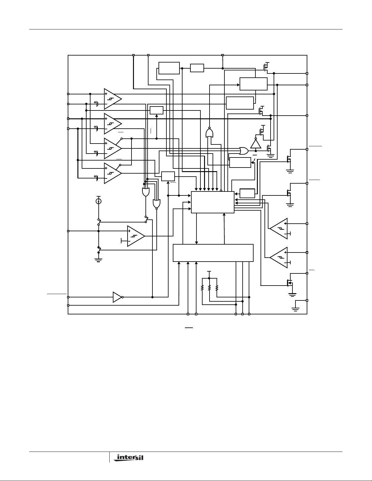
Functional Block Diagram (1 Channel)
www.BDTIC.com/Intersil
ISL6112
12VSENSE
12VIN
3VSENSE
3VIN
CFILTER
50mV
50mV
100mV*
100mV*
VSTBY
I
REF
1.25V
ON AUXEN
ON/OFF
/OFF
ON
12V
UVLO
ON/OFF
POWER-ON
RESET
250µs
3V
UVLO
ON/
OFF
VSTBY
UVLO
LOGIC CIRCUITS
DIGITAL CORE/SERIAL INTERFACE
VSTBY
VSTBY
VAUX CHARGE
PUMP AND
MOSFET
VAUX
OVERCURRENT
THERMAL
SHUTDOWN
VAUX
PWRGD
12VIN
3VIN
12V BIAS
ON/OFF
12VPWRGD
3VPWRGD
10.5V
2.8V
12VGATE
VAUX
3VGATE
PWRGD
FAULT
12VOUT
3VOUT
INT
FORCE
_ON
GPI
BOTH A AND B SLOTS SHARE THE SCL, SDA, A0, A1, A2, INT PINS.
2
SCL
40kΩ x 3
GND
A0A1A2SDA
FN6456.0
September 28, 2007
Page 3
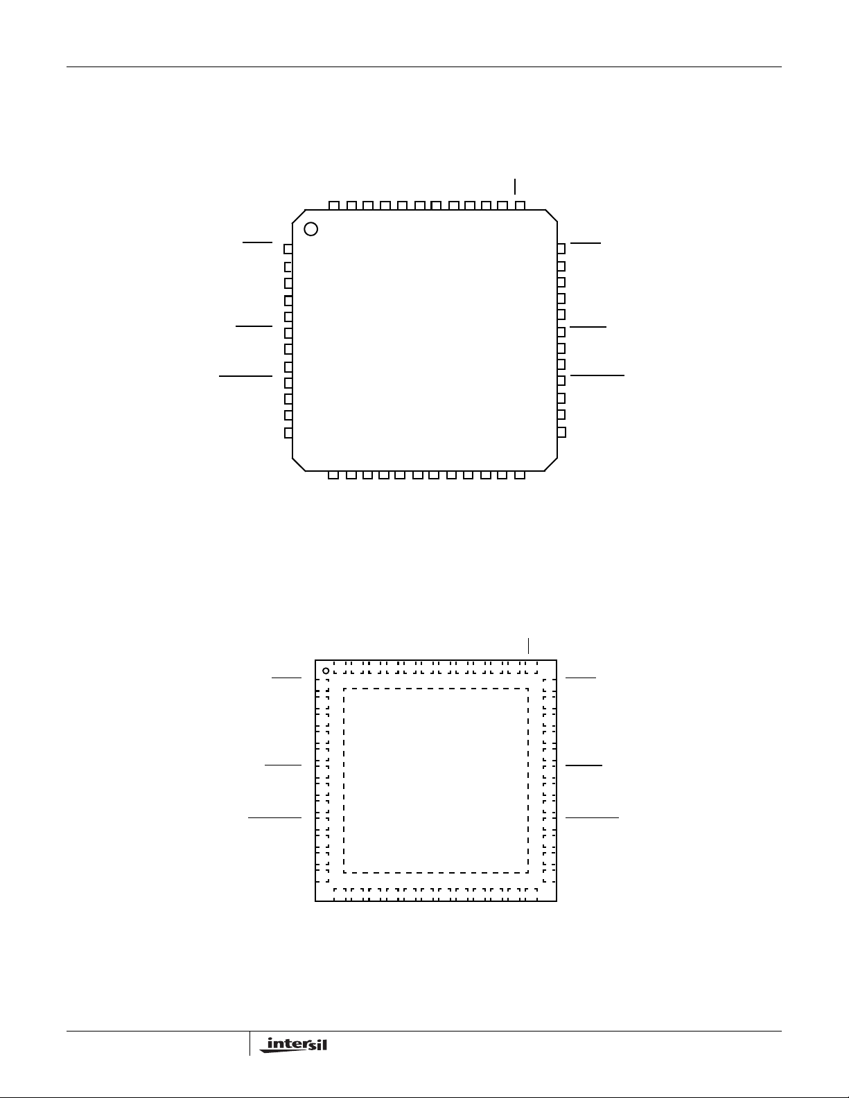
Pinouts
www.BDTIC.com/Intersil
(48 LD 7X7 TQFP)
GND
SCL
SDA
ISL6112
ISL6112
TOP VIEW
ONA
AUXENA
ONB
AUXENB
A0
A1A2GPI_B0
INT
FAULTA
CFILTERA
12VGATEA
GPI_A0
12VINA
PWRGD
12VSENSEA
FORCE_ON
12VOUTA
VSTBYA
3VINA
NC
48 47 45 44 42 41
1
2
3
4
5
A
6
7
8
A
9
10
11
12
13 17 20
14 15 16 18 19 23 24
GND
VAUXA
3VOUTA
3VGATEA
3VSENSEA
NCNCNC
40 39 3746 43 38
21 22
VAUXB
3VOUTB
B
FAULT
36
35
CFILTERB
34
12VGATEB
GND
33
12VINB
32
PWRGD
31
30
29
28
27
26
25
3VGATEB
3VSENSEB
B
NC
12VSENSEB
FORCE_ON
12VOUTB
VSTBYB
3VINB
B
ISL6112
(48 LD 7X7 QFN)
TOP VIEW
12VGATEA
12VSENSEA
FORCE_ON
3
FAULT
CFILTERA
GPI_A0
12VINA
PWRGD
NC
12VOUTA
VSTBYA
3VINA
ONB
SCL
GND
SDA
48 47 46 45 44 43 42 41 40 39 38 37
1
A
2
3
4
5
6
A
7
8
9
A
10
11
12
13 14 15 16 17 18 19 20 21 22 23 24
3VSENSEA
AUXENA
(EXPOSED BOTTOM PAD)
VAUXA
3VOUTA
3VGATEA
ONA
GND
GND
NC
AUXENB
NC
A0
A1A2GPI_B0
NC
3VOUTB
INT
36
FAULTB
35
CFILTERB
34
12VGATEB
33
GND
32
12VINB
31
PWRGD
B
30
NC
29
12VSENSEB
28
FORCE_ON
27
12VOUTB
26
VSTBYB
25
3VINB
VAUXB
3VGATEB
3VSENSEB
B
FN6456.0
September 28, 2007
Page 4
ISL6112
www.BDTIC.com/Intersil
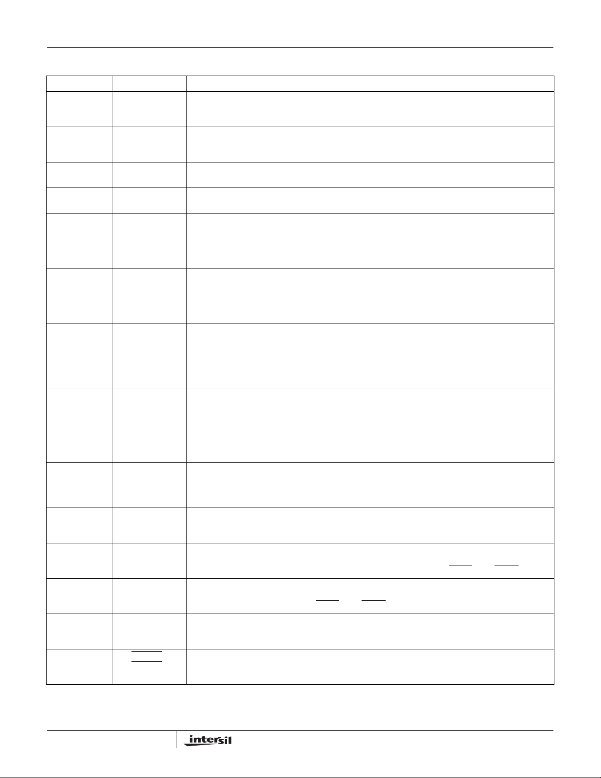
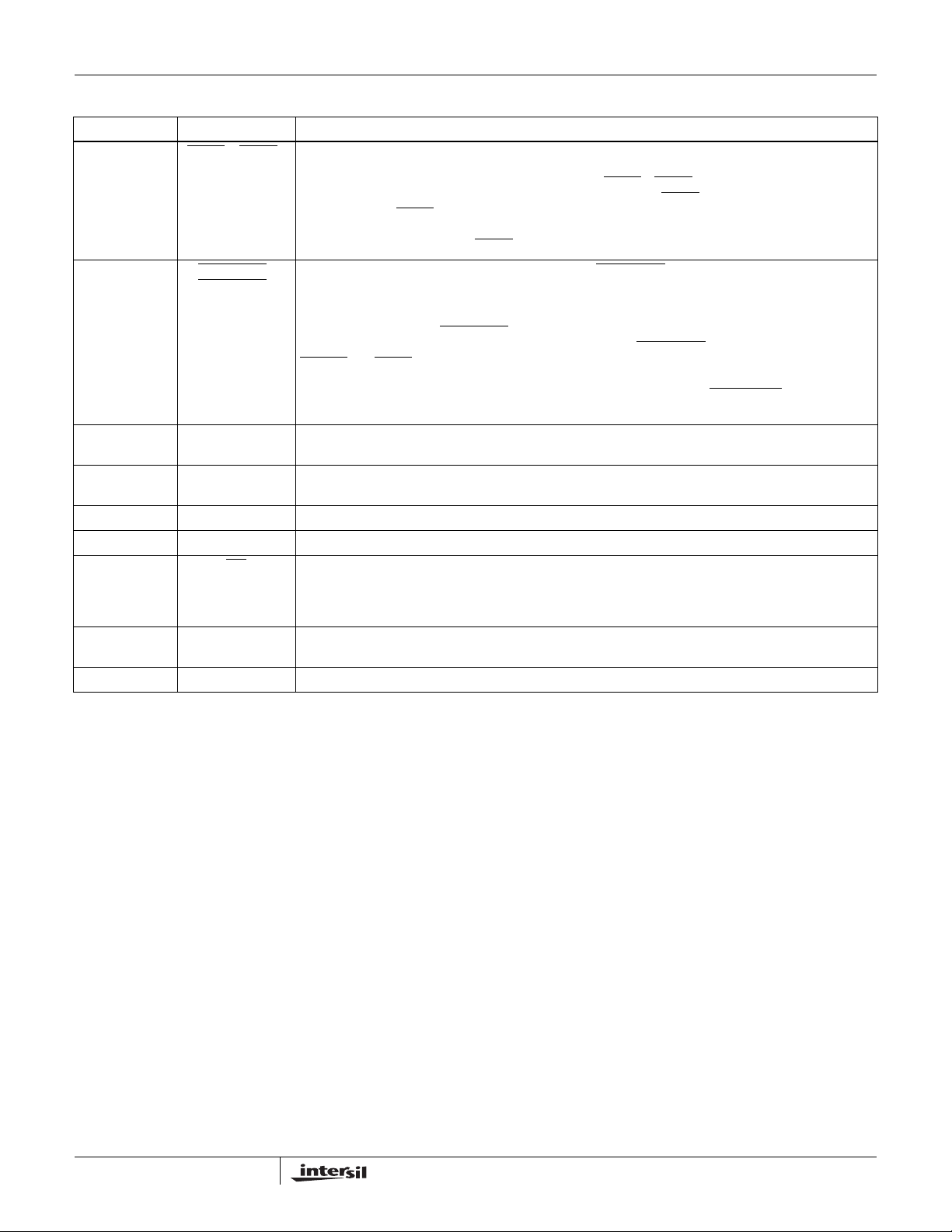
Pin Descriptions (Pin Numbers and Names are Related)
PIN NUMBER PIN NAME PIN FUNCTION
5, 32 12VINA, 12VINB Provides 12VMAIN power supply and the high side of the sense resistor inputs. This must be a Kelvin
connection between IC and sense resistor. An undervoltage lockout circuit (UVLO) prevents the switches
from turning on while this input is less than its lockout threshold.
12, 25 3VINA, 3VINB Provides 3.3VMAIN power supply and the high side of the sense resistor inputs. This must be a Kelvin
connection between IC and sense resistor. An undervoltage lockout circuit (UVLO) prevents the switches
from turning on while this input is less than its lockout threshold.
16, 21 3VOUTA, 3VOUTB 3.3VOUT. Connected to 3.3V FET source. These are used to monitor the 3.3V output voltages for Power
Good status.
10, 27 12VOUTA,
12VOUTB
8, 29 12VSENSEA,
12VSENSEB
13, 24 3VSENSEA,
3VSENSEB
3, 34 12VGATEA
12VGATEB
14, 23 3VGATEA
3VGATEB
11, 26 VSTBYA, VSTBYB 3.3V Standby Input V oltage: Required to support PCI Express V AUX output. Additionally , the SMBus logic
15, 22 VAUXA, VAUXB 3.3VAUX Output s to PCI Express Card Slots: These outputs connect the 3.3AUX pin of the PCI Express
44, 43 ONA, ONB Enable Inputs: Rising-edge triggered. Used to enable or disable the MAINA and MAINB (+3.3V and +12V)
45, 42 AUXENA, AUXENB Level sensitive auxiliary enable Inputs. Used to enable or disable the VAUX outputs. Taking AUXEN low
2, 35 CFILTERA,
CFILTERB
6, 31 PWRGDA
PWRGD
12VOUT. Connected to 12V FET drain. These are used to monitor the 3.3V output voltages for Power
Good status.
12VMAIN low side of sense resistor connection. When either current limit threshold of the load current
across the sense resistor = 50mV is reached, the related 12VGATE pin is modulated to maintain a
constant voltage across the sense resistor and thus a constant current into the load. If the 50mV threshold
is exceeded for tFLT, the isolation protection is tripped and the GATE pin for the affected supply’s external
MOSFET is immediately pulled high. This must be a Kelvin connection between IC and sense resistor.
3.3VMAIN low side of sense resistor connection. When either current limit threshold of the load current
across the sense resistor = 50mV is reached, the related 3V GATE pin is modulated to maintain a constant
voltage across the sense resistor and thus a constant current into the load. If the 50mV threshold is
exceeded for tFLT, the isolation protection is tripped and the GATE pin for the affected supply’s external
MOSFET is immediately pulled low. This must be a Kelvin connection between IC and sense resistor.
12V Gate Drive Outputs: Each pin connects to the gate of an external P-Channel MOSFET. During
power-up, the CGATE and the CGS of the MOSFETs are connected to a 25µA current sink. This controls
the value of dv/dt seen at the source of the MOSFETs. During current limit events, the voltage at this pin
is adjusted to maintain constant current through the switch for a period of tFLT. Whenever an overcurrent,
thermal shutdown, or input undervoltage fault condition occurs, the GATE pin for the affected slot is
immediately brought high. These pins are charged by an internal current source during power-down.
3V Gate Drive Outputs: Each pin connects to the gate of an external N-Channel MOSFET. During powerup, the CGATE and the CGS of the MOSFETs are connected to a 25µA current source. This controls the
value of dv/dt seen at the source of the MOSFET s, and hence the current flowing into the load capacitance.
During current limit events, the voltage at this pin is adjusted to maintain constant current through the
switch for a period of tFLT. Whenever an overcurrent, thermal shutdown, or input undervoltage fault
condition occurs, the GATE pin for the af fected slot is immediately brought low . During power-down, these
pins are discharged by an internal current source.
and internal registers run off of VSTBY to ensure that the chip is accessible during standby modes. A
UVLO circuit prevents turn-on of this supply until VSTBY rises above its UVLO threshold. Both pins must
be externally connected together at the ISL6112 controller.
connectors to VSTBY via internal 400mΩ MOSFETs. These outputs are 1A current limited and protected
against short-circuit faults.
outputs. Taking ON low after a fault resets the +12V and/or +3.3V fault latches for the affected slot. Tie
these pins to GND if using SMI power control. Also, see pin description for FAULT
after a fault resets the respective slot’s Aux Output Fault Latch. Tie these pins to GND if using SMI power
control. Also, see pin description for FAULT
Overcurrent Timers: Capacitors connected between these pins and GND set the duration of CR
is the amount of time for which a slot remains in current limit before its isolation protection is
CR
TIM
invoked.
Power-is-Good Outputs: Open-drain, active-low. Asserted when a slot has been commanded to turn on
B
and has successfully begun delivering power to its respective +12V, +3.3V, and VAUX outputs. Each pin
requires an external pull-up resistor to V
A and FAULTB.
.
STBY
A and FAULTB.
TIM
.
4
FN6456.0
September 28, 2007
Page 5
ISL6112
www.BDTIC.com/Intersil
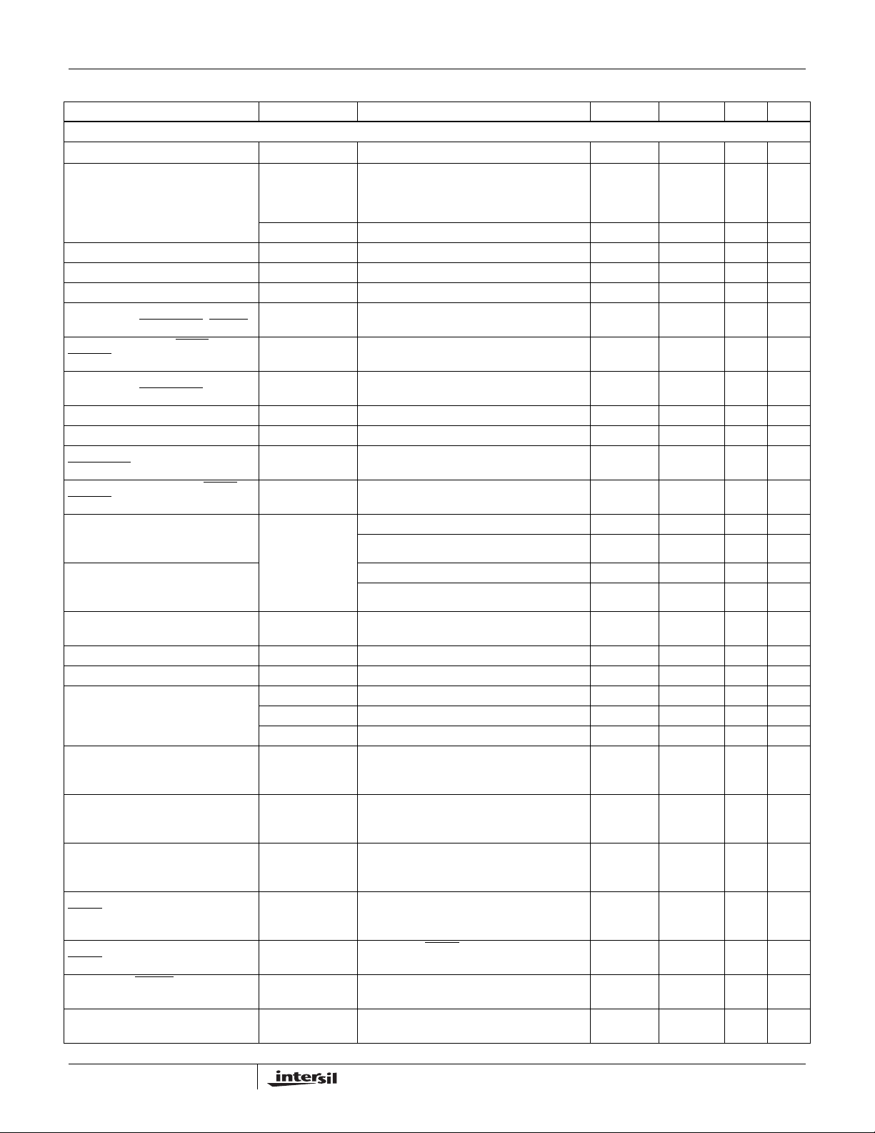
Pin Descriptions (Pin Numbers and Names are Related) (Continued)
PIN NUMBER PIN NAME PIN FUNCTION
1, 36 FAULTA, FAULTB Fault Outputs: Open-drain, active-low. Asserted whenever the isolation protection trips due to a fault
9, 28 FORCE_ONA
FORCE_ON
4, 38 GPI_A0, GPI_B0 General Purpose Inputs: The states of these two inputs are available by reading the Common Status
39, 40, 41 A2, A1, A0 SMBus Address Select Pins. Connect to ground or leave open in order to program device SMBus base
48 SDA Bidirectional SMBus data line.
47 SCL SMBus Clock Input.
37 INT
17, 33, 46 GND IC Reference pins. Connect together and tie directly to the system’s analog GND plane directly at the
7, 18, 19, 20, 30 NC Reserved: Make no external connections to these pins.
Interrupt Output. Open-drain, active-low. output. Asserted whenever a power fault is detected if the
condition (overcurrent, input undervoltage, over-temperature). Each pin requires an external pull-up
resistor to V
fault condition on one of the slot’s MAIN outputs (+12V or +3.3V). FAULT
AUXEN pin low if FAULT
condition occurred on both the MAIN and VAUX output s of the same slot, then both ON and AUXEN must
be brought low to de-assert the FAULT
Enable Inputs: Active-low, level-sensitive. Asserting a FORCE_ON
B
respective slot’s outputs (+12V, +3.3V, and VAUX), while specifically defeating all protections on those
supplies. This explicitly includes all overcurrent and short circuit protections, and on-chip thermal
protection for the VAUX supplies. Additionally included are the UVLO protections for the +3.3V and
+12VMAIN supplies. The FORCE_ON
input pins are intended for diagnostic purposes only. Asserting FORCE_ON
PWRGD
reflect the actual state of each slot’s supplies. There is a pair of register bits, accessible via the SMBus,
which can be set to disable (unconditionally de-assert) either or both of the FORCE_ON
CNTRL Register Bit D[2].
Register, Bits [4:5]. If not used, connect each pin to GND.
address. These inputs have internal pull-up resistors to VSTBY. Address programmed on rising VSTBY.
INTMSK bit (CS Register Bit D[3]) is a logical “0”. This output is cleared by performing an “echo reset” to
the appropriate fault bit(s) in the STAT and/or CS registers. This pin requires an external pull-up resistor
to VSTBY.
device.
. Bringing the slot’s ON pin low resets FAULT if FAULT was asserted in response to a
STBY
was asserted in response to a fault condition on the slot’s VAUX output. If a fault
output.
pins do not disable UVLO protection for the VAUX supplies. These
and FAUL T pins to enter their open-drain state. Note that the SMBus register set will continue to
is reset by bringing the slot’s
input will turn on all three of the
will cause the respective slot’s
pins -- See
5
FN6456.0
September 28, 2007
Page 6

ISL6112
www.BDTIC.com/Intersil
Absolute Maximum Ratings (Note 4) Thermal Information
12VIN, 12VSENSE, 12VOUT . . . . . . . . . . . . . . . . . . . . . . . . +14.5V
VSTBY, 3VIN, 3VSENSE, 3VOUT. . . . . . . . . . . . . . . . . . . . . . . +7V
12VGATE. . . . . . . . . . . . . . . . . . . . . . . . . . . . . . . . . . . -0.3V to 12VI
3VGATE. . . . . . . . . . . . . . . . . . . . . . . . . . . . . . . . . . . . -0.3V to 12VI
Logic I/O . . . . . . . . . . . . . . . . . . . . . . . . . . . . . . . . . . -0.5V to +5.5V
VAUX Output Current . . . . . . . . . . . . . . . . . .Short Circuit Protected
ESD Rating
Human Body Model . . . . . . . . . . . . . . . . . . . . . . . . . . . . . . . . .2kV
Machine Model. . . . . . . . . . . . . . . . . . . . . . . . . . . . . . . . . . . .200V
Charged Device Model . . . . . . . . . . . . . . . . . . . . . . . . . . . . . .1kV
CAUTION: Do not operate at or near the maximum ratings listed for extended periods of time. Exposure to such conditions may adversely impact product reliability and
result in failures not covered by warranty.
NOTES:
is measured with the component mounted on a high effective thermal conductivity test board in free air. See Tech Brief TB379 for details.
1. θ
JA
is measured in free air with the component mounted on a high effective thermal conductivity test board with “direct attach” features. See
2. θ
JA
Tech Brief TB379.
3. For θ
4. All voltages are relative to GND, unless otherwise specified.
, the “case temp” location is the center of the exposed metal pad on the package underside.
JC
Thermal Resistance (Typical) θ
48 Ld 7x7 TQFP Package (Note 1) . . . 57 N/A
48 Ld 7x7 QFN Package (Notes 2, 3) . 27 3
Maximum Junction Temperature . . . . . . . . . . . . . . . . . . . . . . +150°C
Maximum Storage Temperature Range. . . . . . . . . -65°C to +150°C
Pb-free reflow profile . . . . . . . . . . . . . . . . . . . . . . . . . .see link below
http://www.intersil.com/pbfree/Pb-FreeReflow.asp
Operating Conditions
12VMAIN Supply Voltage Range. . . . . . . . . . . . . . . . . +12V ± -10%
3.3VMAIN Supply Voltage Range . . . . . . . . . . . . . . . . +3.3V ± -10%
AUXI Supply Voltage Range . . . . . . . . . . . . . . . . . . . . +3.3V ± -10%
Temperature Range (T
) . . . . . . . . . . . . . . . . . . . . . .-40°C to +85°C
A
(°C/W) θJC (°C/W)
JA
Electrical Specifications 12VIN = 12V, 3VIN = 3.3V, VSTBY = 3.3V, T
PARAMETER SYMBOL CONDITION MIN TYP MAX UNITS
POWER CONTROL AND LOGIC SECTIONS
Supply Current ICC12 HPI Enabled or SMI enabled with no load 0.9 1.5 mA
ICC3.3 0.1 0.2 mA
ICCSTBY 5 6 mA
Undervoltage Lockout Thresholds VUVLO(12V) 12VIN increasing 8 9 10 V
VUVLO(3V) 3VIN increasing 2.1 2.5 2.75 V
VUVLO(STBY) VSTBY increasing 2.8 2.9 2.96 V
Undervoltage Lockout Hysteresis
12VIN, 3VIN
Undervoltage Lockout Hysteresis
VSTBY
Power-Good Undervoltage
Thresholds
Power-Good Detect Hysteresis VHYSPG 30 mV
12VGATE Voltage VGATE (12V) Max. Gate Voltage when Enabled 0 0.4 0.55 V
12VGATE Sink Current IGATE(12VSINK) Start Cycle 17 25 35 µA
12VGATE Pull-up Current (Fault Off) IGATE
3VGATE Voltage VGATE(3V) Minimum Gate Voltage when Enabled 12VIN – 0.3 12VIN – 0.2 12VIN V
3VGATE Charge Current IGATE
3VGATE Sink Current (Fault Off) IGATE(3VSINK) Any fault condition
VHYSUV 180 mV
VHYSSTBY 50 mV
VUVTH(12V) 12VOUT decreasing 10.15 10.5 10.75 V
VUVTH(3V) 3VOUT decreasing 2.7 2.8 2.9 V
VUVTH(VAUX) VAUX decreasing 2.55 2.8 3 V
Any fault condition
(12VPULL-UP)
(3VCHARGE)
(VDD – VGATE) = 2.5V
Start Cycle 17 25 35 µA
VGATE = 2.5V
= TJ = -40°C to +85°C, Unless Otherwise Noted.
A
35 72 - mA
80 105 mA
6
FN6456.0
September 28, 2007
Page 7
ISL6112
www.BDTIC.com/Intersil
Electrical Specifications 12VIN = 12V, 3VIN = 3.3V, VSTBY = 3.3V, T
PARAMETER SYMBOL CONDITION MIN TYP MAX UNITS
CFILTER OVERCURRENT DELAY TIME PINS 2 AND 35 FLOATING
CFILTER Threshold Voltage VFILTER 1.20 1.25 1.30 V
CFILTER Charging Current
Nominal Current Limit Duration =
C
CFILTER
Current Limit Threshold Voltages VTHILIMIT VXIN – VXVSENSE 47.5 50 52.5 mV
Fast-Trip Threshold Voltages VTHFAST VXVIN – VXVSENSE 85 100 115 mV
XVSENSE Input Current ISENSE 0.1 µA
LOW-Level Input Voltage ON,
AUXEN, GPI, FORCE_ON
Output LOW Voltage FAULT
PWRGD
HIGH-Level Input Voltage ON,
AUXEN, GPI, FORCE_ON
Internal Pull-ups to VSTBY (Note 5) RPULL-UP 40 50 kΩ
12VIN, 3VIN Input Leakage Current ILKG,OFF XVIN VSTBY = +3.3V, 12VIN = OFF; 3VIN = OFF 0.5 1 µA
Input Leakage Current, ON, AUXEN,
FORCE_ON
Off-State Leakage Current FAULT
PWRGD
Over-temperature Shutdown and
Reset Thresholds, with Overcurrent
On Slot
Over-temperature Shutdown and
Reset Thresholds, All Other
Conditions (All Outputs Will Latch Off)
Output MOSFET Resistance VAUX
MOSFET
Off-St ate Output Offset Voltage V AUX VOFF(V AUX) VAUX = Off 25 40 mV
Regulated Current Level ILIM(AUX) 0.8 11.2A
Output Discharge Resistance RDIS(12V) 12VOUT = 6.0V 1400 1850 Ω
12V Current Limit Response Time
(See “Typical Application Diagram”
on page 9).
3.3V Current Limit Response Time
(See “Typical Application Diagram”
on page 9).
VAUX Current Limit Response Time
(See “Typical Application Diagram”
on page 9).
Delay from MAIN Overcurrent to
FAULT
Delay from VAUX Overcurrent to
FAULT
ON, AUXEN, PRSNT
Width
Power-On Reset Time after VSTBY
Becomes Valid
x 550k
, PRSNT
,
,
, GPI
Output
Output
Minimum Pulse
IFILTER VXVIN – VXSENSE > VTHILIMIT 2 2.5 3 µA
tFILTER CFILTER Open 10 µs
VIL 0.8 V
VOL IOL = 3mA 0.4 V
VIH 2.1. 5 V
IIL -2 2 µA
ILKG(OFF) GPI ILKG for these two pins measured with
TOV T
(AUX) IDS = 375mA 350 mΩ
r
DS
RDIS(3V) 3VOUT = 1.65V 140 180 Ω
RDIS(VAUX) 3VAUX = 1.65V 350 400 Ω
tOFF(12V) CGATE = 25pF
tOFF(3V) CGATE = 25pF
tSC VAUX = 0V, VSTBY = +3.3V 2.5 µs
tPROP
(12V FAUL T or 3V
FAULT)
tPROP
(VAUXFAULT)
tW (Note 5) 100 ns
tPOR (Note 5) 250 µs
VAUX OFF
increasing, each slot (Note 5) 140 °C
J
decreasing, each slot (Note 5) 130 °C
T
J
increasing, each slot (Note 5) 160 °C
T
J
T
decreasing, each slot (Note 5) 150 °C
J
VIN – VSENSE = 140mV
VIN – VSENSE = 140mV
CFILTER = 0
VIN – VSENSE = 140mV
I
LIM(AUX)
VAUX Output Grounded
to FAULT output CFILTER = 0
= TJ = -40°C to +85°C, Unless Otherwise Noted. (Continued)
A
-2 2 µA
1 2.1 µs
0.3 1 µs
1 µs
1 µs
7
FN6456.0
September 28, 2007
Page 8
ISL6112
www.BDTIC.com/Intersil
Electrical Specifications 12VIN = 12V, 3VIN = 3.3V, VSTBY = 3.3V, T
PARAMETER SYMBOL CONDITION MIN TYP MAX UNITS
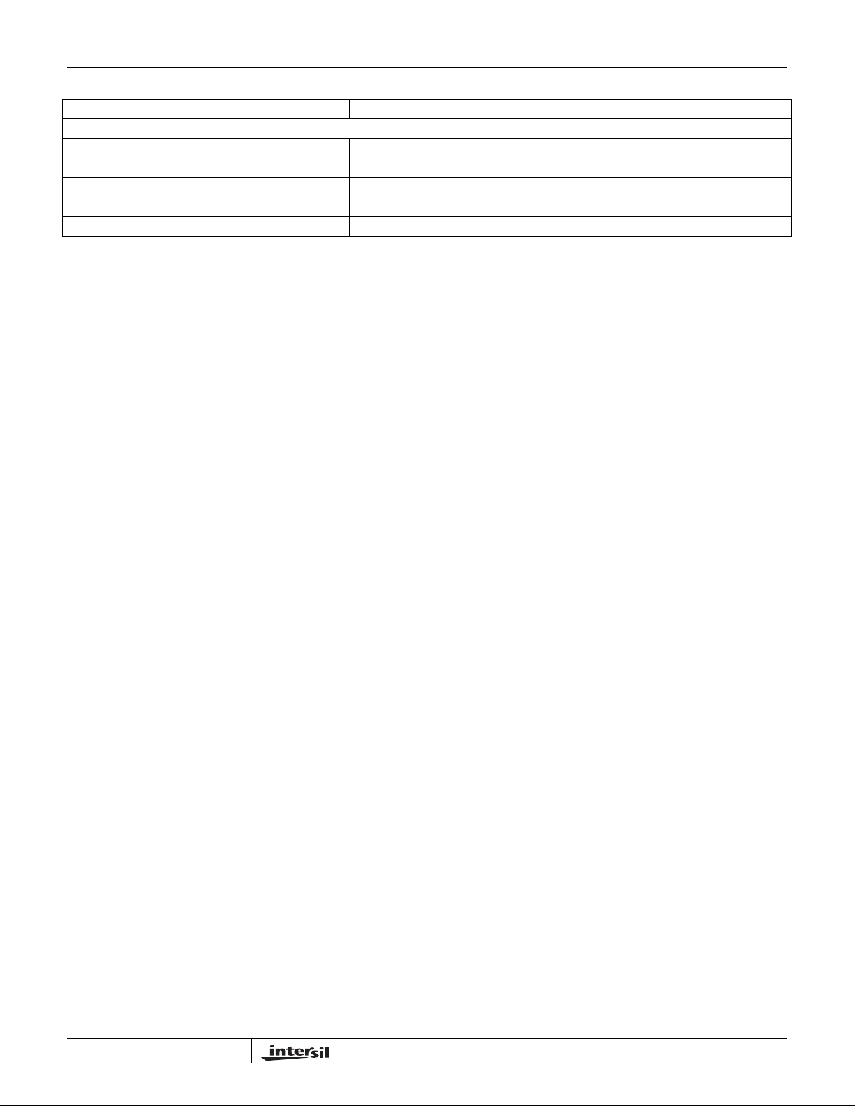
SMBUS TIMING
SCL (clock) period t1 (Note 5) 2.5 µs
Data In setup time to SCL HIGH t2 (Note 5) 100 ns
Data Out stable after SCL LOW t3 (Note 5) 300 ns
Data LOW setup time to SCL LOW t4 (Note 5) 100 ns
Data HIGH hold time after SCL HIGH t5 (Note 5) 100 ns
NOTE:
5. Limits established by design and are not production tested.
= TJ = -40°C to +85°C, Unless Otherwise Noted. (Continued)
A
8
FN6456.0
September 28, 2007
Page 9

Typical Application Diagram
www.BDTIC.com/Intersil
ISL6112
FORCE_ONA
FORCE_ON
GPI_A0
GPI_B0
SMBUS I/O
100k 100k100k100k
B
AUXENA
AUXENB
HOT-PLUG
CONTROLLER
PWRGDA
PWRGDB
SMBUS
BASE
ADDRESS
SYSTEM
POWER
SUPPLY
V
ONA
ONB
FAULTA
FAULTB
10k x 3
SDA
SCL
INT
STBY
+12V
+3.3V
VSTBY
V
V
VSTBY
C1
STBY
STBY
C2
10k x 4
10k x 4
0.1µF
2
CFILTERA
35
CFILTERB
9
FORCE_ON
28
FORCE_ON
4
GPI_A0
38
GPI_B0
45
AUXENA
42
AUXENB
44
ONA
43
ONB
6
PWRGD
31
PWRGD
1
FAULT
36
FAULTB
41
A0
40
A1
39
A2
37
INT
47
SCL
48
SDA
SDA
SCL
INT
11 26
VSTBYBVSTBYA VAUXA
12VSENSEA
12VGATEA
A
B
3VSENSEA
ISL6112
12VSENSEB
12VGATEB
A
B
A
MANAGEMENT
CONTROLLER
3VSENSEB
0.1µF
12VINA
12VOUTA
3VINA
3VGATEA
3VOUTA
12VINB
12VOUTB
3VINB
3VGATEB
3VOUTB
VAUXB
GND
GND
GND
PCI-EXPRESS CONNECTOR
15
0.1µF
5
8
#CGS
*R12VGATEA
22nF
3
#CGD
6800pF
10
12
13
14
16
#
C
GATE
22nF
32
29
#CGS
22nF
34
27
25
24
23
21
22
17
33
46
* Values for R
depending upon the C
# These components are not required for ISL6112
operation but can be implemented for GATE output
slew rate control (application specific)
• Bold lines indicate high current paths
^ R
15Ω
0.1µF
*R3VGATEA
15Ω
0.1µF
*R12VGATEB
15Ω
#
CGD
6800pF
0.1µF
*R3VGATEB
15Ω
#CGATE
22nF
12VGATE
value is application specific
SENSE
RSENSE^
RSENSE^
0.015Ω
RSENSE^
RSENSE^
0.015Ω
PCI-EXPRESS CONNECTOR
and R
GS
may vary
3VGATE
of the external MOSFETs.
PCI
EXPRESS
BUS
3.3AUX
375mA
12V
2.1A (x4/x8)
3.3V
3.0A
12V
2.1A (x4/x8)
3.3V
3.0A
3.3AUX
375mA
PCI
EXPRESS
DATA BUS
9
FN6456.0
September 28, 2007
Page 10

ISL6112
www.BDTIC.com/Intersil
Functional Description
The ISL6112 protects the power supplies in PCI-Express
systems that utilize hot-pluggable add-in cards. This IC
together with two each of N-Channel and P-Channel
MOSFETs, four current sense resistors and a few external
passive components, provide a compliant hot plug power
control solution to any combination of two PCI-Express X1,
X4, X8 or X16 slots.
The ISL6112 primarily features start-up in-rush current
protection, maximum current regulated (CR) levels for each
of the MAIN and AUX outputs, programmable CR duration
so that both fault isolation protection and imperviousness to
electrical transients are provided. The ISL6112 also offers
input and output voltage supervisory functions and two
operational system interfaces for implementation flexibility.
In-Rush Current Protection
When any electronic circuitry is powered up, there is an
in-rush of current due to the charging of bulk capacitance
that resides across the circuit board’s supply pins. This
transient in-rush current may cause the systems supply
voltages to temporarily droop out of regulation, causing data
loss or system lock-up. The ISL6112 addresses these iss ues
by limiting the in-rush currents to the PCI-Express add-in
cards, and thereby controlling the rate at which the loads
circuits turn-on. See Figures 2, 3, 4, 5, 6 and 7 for AUX and
MAIN turn-on examples illustrating the current limiting
capabilities across a variety of compensation component
values.
MAIN Supply Overcurrent Protection
For each of the 3VMAIN and 12VMAIN supplies, the current
regulated (CR) levels are set by a sub ohm value sense
resistor. The value for the 12VMAIN is dependant on the size
of the PCI-Express connector (X1, X4/X8 or X16) to be
powered. The voltage across this resistor is compared to a
50mV internal reference providing a nominal CR protection
level which would be set above the maximum specified slot
limits. The 3.3VMAIN supply can use a 15mΩ sense resistor
compared to a 50mV reference to provide a nominal
regulated current limit of 3.3A, as this supply has a common
3A maximum across all slot sizes. For both MAIN supplies,
there is a Way Overcurrent (WOC) shutdown protocol that is
without a CR duration. WOC is invoked if the load current
causes the RSENSE voltage to be >100mV. See Figures 10
and 11.
VAUX Supply Overcurrent Protection
The VAUX load current is internally monitored and controlled
via an internal power FET. This FET has a typical r
320mW at a VAUX current of 375mA to minimize distribution
losses to typically <100mV through the IC. Using active
monitoring and control, the ISL6112 provides nominal
limiting to ~1000mA of load current across the temperature
range and for various loading conditions. See Figures 2, 12
and 13 for examples of this performance.
DS(ON)
of
Current Regulation (CR) Duration
The CR duration for each slot is set by an external capacitor
between the associated CFILTER pin and ground. This
feature masks current transients and overcurrents prior to
supply turn-off. Once the CR duration has expired, the IC
then quickly turns-off the associated MAIN outputs via its
external FET s or the failed AUX output, unloading the faulted
load card from the supply voltage rails.
UVLO, Power Good and FAULT
The ISL6112 incorporates undervoltage lock out (UVLO)
protections on each of the four MAIN VIN and two VSTBY
supplies to prevent operation during a ‘brown out’ condition.
Likewise on the outputs are minimum voltage compliances
that must be satisfied for the Power Good output, PWRGD to
be asserted. There is some hysteresis on the UVLO levels
as the voltage on VIN decreases to ensure IC operation
below the minimum operating supply standards. The FAULT
output is asserted (low) whenever there is an OC, OT or UV
condition. The FAUL T
is deasserted.
is cleared once the appropriate enable
Operational System Interfaces
The ISL6112 employs two system interfaces: the hardware
Hot-Plug Interface (HPI) and the System Management
Interface (SMI). The HPI I/O includes ON, AUXEN, FAULT
and PWRGD
whose signals conform to the levels and timing of the SMBus
specification; see “SMI only Control Applications” on
page 17 The ISL6112 can be operated exclusively from
either the SMI or HPI, or can employ the HPl for power
control while continuing to use the SMI for access to all but
the power control registers.
In addition to the basic power control features of the ISL6112
accessible by the HPI, the SMI also gives the host access to
the following information from the part:
• Fault conditions occurring on each supply. These faults
include Overcurrent, Over-Temperature and undervoltage
• GPI pin status when using the System
When using the System Management Interface for power
control, do not use the Hot-Plug Interface. Conversely, when
using the Hot-Plug Interface for power control, do not execute
power control commands over the System Management
Interface bus (all other register accesses via the SMI bus
remain permissible while in the HPI control mode). When
utilizing the SMI exclusively, the HPI input pins (ON, AUXEN,
and FORCE_ON
(disabling HPI when SMI control is used). This configuration
safeguards the power slots in the event that the SMBus
communication link is disconnected for any reason.
Additionally, when utilizing the HPI exclusively, the SMBus
(or SMI) will be inactive if the input pins (SDA, SCL, A0, A1,
and A2) are configured as shown in Figure 1.
]; the SMI I/O consists of SDA, SCL, and INT,
) should be configured, as shown in Figure 1
10
FN6456.0
September 28, 2007
Page 11

ISL6112
www.BDTIC.com/Intersil
V
STBY
INT
DISABLING SMI WHEN HPI CONTROL IS USED
V
STBY
DISABLING HPI WHEN SMI CONTROL IS USED
FIGURE 1. I/O CONFIGURATION FOR DISABLING HPI/SMI
CONTROL
100k
100k
100k
100k
100k
9
FORON#_A
28
FORON#_B
45
AUXENA
42
AUXENB
44
ONA
43
ONB
SCL
SDA
INT#
A2
A1
A0
ISL6112 Bias, Power-On Reset and Power Cycling
The ISL6112 utilizes VSTBY as the only supply source.
VSTBY is required for proper operation of the ISL6112’s
SMBus and registers and must be applied at all times. A
Power-On Reset (POR) cycle is initiated after VSTBY rises
above its UVLO threshold and remains satisfied for 250µs.
All internal registers are cleared after POR. If VSTBY is
recycled, the ISL6112 enters a new power-on-reset cycle.
VSTBY must be the first supply voltage applied followed by
the MAIN supply inputs of 12VIN and 3VIN. The SMBus is
ready for access at the end of the POR cycle (250µs after
VSTBY is valid). During t
, all outputs remain off.
POR
Enabling the VAUX Outputs
Upon asserting an AUXEN input, the related internal power
switch turns on connecting the nominally 3.3V VSTBY
supply to its V AUX load. The turn-on is slew rate limited and
invokes the ICs current regulation feature so as to not droop
the supply due to in-rush curren t load. Figure 2 il lustrates the
VAUX turn-on performance into a 10Ω, 100µF load.
Standby Mode
Standby mode is entered when one or more of the MAIN
supply inputs (12VIN and/or 3VIN) is absent, below its
respective UVLO threshold or OFF. The ISL6112 also has
3.3V auxiliary outputs (VAUXA and VAUXB), satisfying an
optional PCI Express requirement. These outputs are fed
from the VSTBY input pins, they are independent of the
MAIN outputs and are controlled by the AUXEN input pins or
via their respective bits in the control registers. Should the
MAIN supply inputs fall below their respective UVLO
thresholds, VAUX will still function as long as VSTBY is
compliant. Prior to standby mode, ONA and ONB (or the
control registers' MAINA and MAINB bits) inputs must be
deasserted or else the ISL6112 will assert it s F AUL T
outputs.
If an undervoltage condition on either of the MAIN supply
inputs is detected, the INT
will also assert if interrupts are
enabled.
VAUX
VAUX
AUXEN
AUXEN
IAUX
IAUX
FIGURE 2. VAUX TURN-ON R
LOAD
= 10Ω, C
LOAD
= 100µF
Enabling the MAIN GATE outputs
When a slot's MAIN supplies are off, th e 12 VGATE pin is
held high with an internal pull-up to the 12VIN voltage.
Similarly, the 3VGATE pin is internally held low to GND.
When the MAIN supplies of the ISL6112 are enabled by
asserting ON, the related 3VGATE and 12VGATE pins are
each connected to a constant current supply. For the
3VGATE pin, this is nominally a 25µA current source and for
the 12VGATE pin, this is nominally a -25µA current sink. The
3VGATE will be charged up to the 12VIN voltage whereas
the 12GATE will be pulled down to GND for maximum
enhancement of the N-Channel and P-Channel FETs,
respectively.
Estimating In-Rush Current and V
Slew Rate at
OUT
Start-up
The expected in-rush current can be estimated by using
Equation 1:
C
⎛⎞
LOAD
I
IN RUSH–
NOMINALLY 25μA
=
with 25µA being the GATE pin charge current, C
load capacitance, and C
including C
of the external MOSFET and any external
ISS
GATE
capacitance connected from the GATE output pin to the
GATE reference, GND or source.
An estimate for the output slew rate of 3.3V outputs and 12V
outputs where there is little or no external 12VGATE output
capacitors, can be had from Equation 2:
dv/dt VOUT NOMINALLY
=
------------------- -
⎜⎟
C
⎝⎠
GATE
LOAD
is the total GATE capacitance
I
LIM
------------------- -
C
LOAD
(EQ. 1)
is the
(EQ. 2)
11
FN6456.0
September 28, 2007
Page 12

ISL6112
www.BDTIC.com/Intersil
where I
capacitance. As a consequence, the CR duration, t
= 50mV/R
LIM
SENSE
and C
LOAD
is the load
FILTER,
must be programmed to exceed the time it will take to fully
charge the output load to the input rail voltage level.
MAIN Outputs (Start-up Delay and Slew-Rate
Control)
The 3.3V outputs act as source followers. In this mode of
operation, V
SOURCE
associated output reaches 3.3V. The voltage on the gate of
the MOSFET will then continue to rise until it reaches 12V,
which ensures minimum r
the MOSFET is optionally configured as a Miller integrator to
adjust the V
OUT
which is connected between the MOSFET’s gate and drain.
In this configuration, the feedback action from drain to gate
of the MOSFET causes the voltage at the drain of the
MOSFET to slew in a linear fashion at a rate estimated by
Equation 3:
dv/dt VOUT NOMINALLY
Table 1 approximates the output slew-rate for various values
of C
(external C
when start-up is dominated by GATE capacitance
GATE
GATE
external MOSFET for the 3.3V rail; C
TABLE 1. 3.3V AND 12V OUTPUT SLEW-RATE SELECTION
FOR GATE C APACIT A NCE D OMI NATED ST A RT-UP
CGATE or C
0.01µF* 2.5V/ms
0.022µF* 1.136V/ms
0.047µF 0.532 V/ms
0.1µF 0.250V/ms
GD
= [V
– V
GATE
. For the 12V outputs, when
DS(ON)
TH(ON)
] until the
ramp time by having a CGD capacitor,
=
25μ A
-------------- -
C
GD
(EQ. 3)
from GATE pin to ground plus CGS of the
for the 12V rail).
GD
| IGATE | = 25µA
dv/dt (load)
FIGURE 3. 12VMAIN START-UP R
= 470µF
C
LOAD
C
RESPONDING TO UNSHOWN MAIN SUPPLY
FILTER
FIGURE 4. 3VMAIN START-UP R
LOAD
LOAD
CGD = 6800pF
CGS = 22nF
= 10Ω,
C
GATE
= 2Ω, C
LOAD
12V
12V
GATE
12I
OUT
C
FILTER
3V
OUT
3V
GATE
3I
OUT
C
FILTER
= 22nF
= 470µF
OUT
*Values in this range will be affected by the internal parasitic
capacitances of the MOSFETs used, and should be verified
experimentally.
Note that all of these performance estimates are useful only for
first order time and loading expectations as they do not look at
other significant loading factors. Figures 3, 4, 5, 6 and 7
illustrate empirically the discussed turn-on performance with the
noted loading and compensation conditions.
Notice the degree of control over the in-rush current and the
GATE ramp rate as the and values are changed thus providing
for highly customizable turn-on characteristics.
In some scope shots although the C
shows a ramping
FILTER
in the absence of excessive displayed loading current the
C
is responding to the other MAIN supply current that
FILTER
is not displayed.
All scope shots were taken from the ISL6112EVAL1Z with
FIGURE 5. 12VMAIN START-UP RLOAD = 10Ω,
any component changes noted.
12
C
LOAD
= 470µF
12V
12V
12I
C
FILTER
CGD = 6800pF
CGS = 2200pF
September 28, 2007
OUT
GATE
OUT
FN6456.0
Page 13

C
www.BDTIC.com/Intersil
RESPONDING TO UNSHOWN MAIN SUPPLY
FILTER
C
GATE
3V
GATE
3V
OUT
3I
OUT
C
FILTER
= 2200pF
ISL6112
.
12V
OUT
12I
OUT
12V
GATE
C
FILTER
FIGURE 6. 3VMAIN START-UP R
FIGURE 7. 12VMAIN START-UP R
= 470µF
C
LOAD
LOAD
LOAD
= 2Ω, C
CGD = 9800pF
CGS = 2200pF
= 10Ω,
LOAD
= 470µF
12V
12V
12I
OUT
C
FILTER
OUT
GATE
Current Regulation (CR) Function
The ISL6112 provides a current regulation and limiting
function that protects the input voltage supplies against
excessive loads, including short circuits. When the current
from any of a slots MAIN outputs exceeds the current limit
threshold (I
t
FILTER
MAIN supplies are shut off, as shown in Figures 8 and 9.
Should the load current cause a MAIN outputs V
exceed V
no t
FILTER
= 50mV/R
LIM
) for a duration greater tha n
SENSE
, the isolation protection is tripped and both related
to
SENSE
THFAST
, the outputs are immediately shut off with
delay, as shown in Figures 10 and 11.
FIGURE 8. 12VMAIN CR AND SHUT-DOWN
3I
OUT
3V
OUT
C
FILTER
FIGURE 9. 3VMAIN CR AND SHUT-DOWN
12V
OUT
12I
OUT
12V
C
3V
GATE
FILTER
GATE
FIGURE 10. 12VMAIN WOC SHUT-DOWN
13
FN6456.0
September 28, 2007
Page 14

ISL6112
www.BDTIC.com/Intersil
3V
GATE
C
FILTER
3V
3I
OUT
OUT
VAUX
IAUX
C
FILTER
FIGURE 11. 3VMAIN WOC SHUT-DOWN
The VAUX outputs have a different isolation protection
function. The VAUX isolation circuit does not incorporate a
fast-trip detector, instead they regulate the output current
into a fault to avoid exceeding their operating current limit.
The protection circuit will trip due to an overcurrent on VAUX
when the programmable CR duration timer, t
This use of the t
timer prevents the circuit from
FILTER
FILTER
expires.
tripping prematurely due to brief current transients. See
Figures 12 and 13 for illustrations of the VAUX protection
performance into a slight OC and more severe OC condition
respectively. The ISL6112 AUX current control responds
proportionally to the severity of the OC condition resulting in
faster VAUX pull-down and current regulation until t
FILTER
has expired.
VAUX
IAUX
C
FILTER
FIGURE 13. VAUX WOC REGULATION AND SHUT-DOWN
Following a fault condition, the outputs can be turned on
again via the ON inputs (if the fault occurred on one of the
MAIN outputs), via the AUXEN inputs (if the fault occurred
on the AUX outputs), or by cycling both ON and AUXEN (if
faults occurred on both the MAIN and AUX outputs). A fault
condition can alternatively be cleared under SMI control of
the ENABLE bits in the CNTRL registers (See “Control
Register Bits D[1:0]” on page 19). When the circuit
protection trips, FAULT
will be asserted if the outputs were
enabled through the Hot-Plug Interface inputs. If SMI is
enabled, INT
masked). Note that INT
will be asserted (unless interrupts are
is deasserted by writing a Logic 1
back into the respective fault bit position(s) in the STAT
register or the “Common Status Register (CS) 8-Bits,
Read/Write” on page 23.
The ISL6112 current regulation duration (t
FILTER
) is
individually set for each slot by an external capacitor at the
CFILTER pin to GND. Once the CR mode is entered, the
external cap is charged with a 2.5µA current source to
1.25V. Once this threshold has been reached, the IC then
turns-off only the related faulted output(s), either both of the
MAIN (external FETs) and or the AUX (internal FET) and
sets the FAULT
for C
FILTER
C
FILTER
output low. For a desired t
is given by Equation 4:
nominal t
--------------------------------------------
=
FILTER
500kΩ
FILTER
, the value
(EQ. 4)
where 500kΩ is the nominal V
where t
FILTER
FIGURE 12. VAUX OC REGULATION AND SHUT-DOWN
for I
Specifications Table” on page 6. See Table 2 for nominal
t
FILTER
and V
FILTER
times for given C
14
FILTER
/nominal I
FILTER
and
is the desired response time with the values
being found in the “Electrical
FILTER
cap values.
FILTER
FN6456.0
September 28, 2007
Page 15

ISL6112
www.BDTIC.com/Intersil
For the ISL6112, there is a minimum t
FILTER
consideration
since the ISL6112 has it s CR feature invoked as it turns-on the
FETs into the load. There is a maximum bulk capacitance
specified for each power level supported that needs to be
charged at the CR limit. This in-rush current time must be
considered when determining the t
TABLE 2.
NOMINAL t
C
NOTE: Nominal CR_DUR = C
.
CAPACITANCE (µF) TIME (ms)
FILTER
Open 0.01
0.01 5
0.022 11
0.047 24
0.1 50
FILTER
FILTER
duration.
FILTER
DURATION
cap (μF) * 500kΩ.
Power-Down Cycle
When a slot is turned off either under HPI or SMI control ,
internal discharge FETs are connected to the output load
providing a discharge path for load capacitance connected to
the part’s outputs ensuring that the outputs are pulled to
GND. This is a compliancy requirement if a replacement add
in card will be inserted into the slot.
Thermal Shutdown
The internal VAUX MOSFETs are protected against damage
not only by current limiting, but by a dual-mode
over-temperature protection scheme as well. Each slot
controller on the ISL6112 is thermally iso lated from the other .
Should an overcurrent condition raise the junction
temperature of one slot’s controller and pass elements to
+140°C, all of the outputs for that slot (including VAUX) will
be shut off and the slots FAULT
other slots operating condition will remain unaffected.
However, should the ISL6112’s die temperature exceed
+160°C, both slots (all outputs, including VAUXA and
VAUXB) will be shut off, whether or not a current limit
AUXEN
VAUX
3VAUX_UV
ON
MAIN
12VOUT_UV
3VOUT_UV
FORCE_ON
FORCE_EN
output will be asserted. The
(1)
(2)
(3)
(1)
(4)
(3)
(3)
(1)
(5)
condition exists. A +160°C over-temperature condition
additionally sets the over-temperature bit (OT_INT) in the
“Common Status Register (CS) 8-Bits, Read/Write” on
page 23.
PWRGD Outputs
The ISL6112 has two PWRGD outputs, one for each slot.
These are open-drain, active-low outputs that require an
external pull-up resistor to VSTBY. Each output is asserted
when a slot has been enabled and has successfully begun
delivering power to its respective +12V, +3.3V, and VAUX
outputs. An equivalent logic diagram for PWRGD
is shown in
Figure 14.
FORCE_ON Inputs
These level-sensitive, active-low inputs are provided to facilitate
designing or debugging systems using the ISL6112. Asserting
FORCE_ON
will turn on all three of the respective slot’s
outputs (12MAIN, 3MAIN, and V AUX), while specifically
defeating all overcurrent and short circuit protections, and onchip thermal protection for the VAUX supplies. Additionally ,
asserting FORCE_ON
will disable all of the input and output
UVLO protections, with the sole exception of the VSTBY input
UVLO.
Asserting FORCE_ON
FAULT
outputs to enter their open-drain state. Additionally,
will cause the slot PWRGD and
there are two SMBus accessible register bits (See Control
Register Bit D[2] in Tables 5 and 7), which can be set to
disable the corresponding slot’s FORCE_ON
pins. This
allows system software to prevent these hardware
overrides from being inadvertently activated during normal
use. When not used, each FORCE_ON
pin can be
connected to VSTBY using an external pull-up resistor or
simply shorted to VSTBY.
General Purpose Input (GPI) Pins
Two pins on the ISL6112 are available for use as GPI pins. The
logic state of each of these pins can be determined by polling
Bits [4:5] of Common S t atus Reg ister. Both of these inputs are
compliant to 3.3V. If GPI is unused, connect each to GND.
VSTBY
PWRGD
(1)
External pin
(2)
CNTRL Register Bit D[0]
(3)
Internal flag
(4)
CNTRL Register Bit D[1]
(5)
CNTRL Register Bit D[2]
FIGURE 14. PWRGD LOGIC DIAGRAM
15
FN6456.0
September 28, 2007
Page 16

Timing Diagrams
www.BDTIC.com/Intersil
VSTBY
DATA IN
DATA OUT
UVLO
SCL
SDA
SDA
+3.3V
ISL6112
t
4
t
2
t
3
FIGURE 15. SMBUS TIMING
t
5
AUXEN
VAUX_OUT
I
AUX_OUT
ON
12VOUT
3VOUT
PWRGD_
I3VOUT
FAULT
ILIM(AUX)
ILIM(3V)
_
INT*
VIH VIH
0
tPOR
0
STEADY-STATE
I
0
0
0
0
0
ISTEADY-STATE
0
0
0
FIGURE 16. HOT-PLUG INTERFACE OPERATION
VIL
tFLT
VIH
**
* INT DE-ASSERTED BY SOFTWARE
VIL
tFLT
VIH
ISL6112 DEVICE ADDRESS
S1000A2A1A00A00000XXXA D4D5D6 D3 D2 D1 D0D7 A P
DATA
START
CLK
R/W = WRITE ACKNOWLEDGE ACKNOWLEDGE
MASTER TO DEVICE TRANSFER,
i.e., DATA DRIVEN BY MASTER.
COMMAND BYTE TO ISL6112
DATA BYTE TO ISL6112
DEVICE TO MASTER TRANSFER,
i.e., DATA DRIVEN BY DEVICE.
FIGURE 17. WRITE_BYTE PROTOCOL
16
ACKNOWLEDGE
FN6456.0
September 28, 2007
Page 17

Timing Diagrams (Continued)
www.BDTIC.com/Intersil
ISL6112
ISL6112 DEVICE ADDRESS
S1000A2A1A0 A2A1A00A00000XXXAS1 0 100 D4D5D6 D3 D2 D1 D0AD7 /AP
DATA
START
CLK
R/W = WRITE R/W = READACKNOWLEDGE ACKNOWLEDGE ACKNOWLEDGE NOT ACKNOWLEDGE
COMMAND BYTE TO ISL6112 ISL6112 DEVICE ADDRESS DATA READ FROM ISL6112
MASTER TO DEVICE TRANSFER,
i.E., DATA DRIVEN BY MASTER.
FIGURE 18. READ_BYTE PROTOCOL
ISL6112 DEVICE ADDRESS
S1000A2A1A01A D4D5D6 D3 D2 D1 D0D7 /A P
DATA
START
CLK
R/W = READ
MASTER TO DEVICE TRANSFER,
i.e., DATA DRIVEN BY MASTER.
FIGURE 19. RECEIVE_BYTE PROTOCOL
Hot-Plug Interface (HPI)
Once the input supplies are above their respective UVLO
thresholds, the Hot-Plug Interface can be utilized for power
control by enabling the control input pins (AUXEN and ON)
for each slot. In order for the ISL6112 to switch on the V AUX
supply for either slot, the AUXEN control must be enabled
after the power-on-reset delay, t
(typically, 250µs), has
POR
elapsed.
System Management Interface (SMI)
The ISL6112’s System Manag ement Interface uses the
Read_Byte and Write_Byte subset of the SMBus protocols
to communicate with its host via the System Management
Interface bus. The INT
output signals the controlling
processor that one or more events need attention, if an
interrupt-driven architecture is used. Note that the ISL6112
does not participate in the SMBus Alert Response Address
(ARA) portion of the SMBus protocol.
Fault Reporting and Interrupt Generation
SMI ONLY CONTROL APPLICATIONS
In applications where the ISL6112 is controlled only by the
SMI, ON and AUXEN are connected to GND and the
FORCE_ON
in Figure 1 or shorted. In these cases, the ISL6112’s FAULT
outputs and STATUS Register Bit D[7] (FAULT) are not
activated as fault status is determined by polling STATUS
Register Bits D[4], D[2], D[0] and CS (Common Status)
pins are connected to VSTBY either as shown
START
BYTE READ FROM ISL6112
ACKNOWLEDGE
Register Bits D[2:1]. Individual fault bits in STAT and CS
registers are asserted after power-on-reset when:
• Either or both CNTRL Register Bits D[1:0] are asserted,
• 12VIN, 3VIN, or VSTBY input voltage is lower than its
• The fast OC circuit isolation protection has tripped, OR
• The slow OC circuit isolation protection has tripped AND
• The slow OC circuit isolation protection has tripped AND
• The ISL6112’s global die temperature > +1 60°C
Once asserted, to clear any one or all STATUS Register Bits
D[4], D[2], D[0] and/or CS Register Bits D[2], D[1], a
software subroutine can perform an “echo reset” where a
Logical “1” is written back to those register bit locati ons that
have indicated a fault. This method of “echo reset” allows
data to be retained in the STATUS and/or CS registers until
such time as the system is prepared to operate on that data.
The ISL6112 can operate in interrupt mode or polled mode.
For interrupt-mode operation, the open-drain, active-LOW
INT
INTMSK bit (CS Register Bit D[3]) has been reset to Logical
“0”. Once activated, the INT
the fault conditions previously listed and deasserted when
one or all STAT Register Bits D[4], D[2], D[0] and/or CS
Register Bits D[2], D[1] are reset upon the execution of an
SMBus “echo reset” WRITE_BYTE cycle. For polled-mode
operation, the INTMSK bit should be set to Logical “1,”
thereby inhibiting INT
DEVICE TO MASTER TRANSFER,
i.e., DATA DRIVEN BY DEVICE.
NOT ACKNOWLEDGE
DEVICE TO MASTER TRANSFER,
i.e., DATA DRIVEN BY DEVICE.
STOP
AND
respective ULVO threshold, OR
its filter time-out has expired, OR
Slot die temperature > +140°C, OR
output signal is activated after power-on-reset if the
output is asserted by any one of
output pin operation.
17
FN6456.0
September 28, 2007
Page 18

ISL6112
www.BDTIC.com/Intersil
For those SMI control applications where the FORCE_ON
inputs are needed for diagnostic purposes, the FORCE_ON
inputs must be enabled; that is, CNTRL Register Bit D[2]
should read Logical “0.” Once FORCE_ON
asserted, all output voltages are present with all circuit
protection features disabled, including over-temperature
protection on VAUX outputs. To inhibit FORCE_ON
operation, a Logical “1” shall be written to the CNTRL
Register Bit D[2] location(s)
HPI-ONLY CONTROL APPLICATIONS
In applications where the ISL6112 is controlled only by HPI,
SMBus signals SCL, SDA, and INT
VSTBY as shown in Figure 1. In this configuration, the
ISL6112’s FAULT
and become asserted when:
Either or both external ON and AUXEN input signals are
asserted, AND
• 12VIN, 3VIN, or VSTBY input voltage is lower than its
respective ULVO threshold, OR
• The fast OC circuit isolation protection has tripped, OR
• The slow OC circuit isolation protection has tripped AND
its filter time-out has expired, OR
• The slow OC circuit isolation protection has tripped AND
Slot die temperature > +140°C, OR.
• The ISL6112’s global die temperatur e > +160°C
.
In order to clear F A ULT outputs once asserted, either or both
ON and AUXEN input signals must be deasserted. Please
see FAULT
FORCE_ON
FAULT
and PWRGD outputs are deasserted once
FORCE_ON
outputs are activated af ter po we r-on-r eset
pin description for additional information. If the
inputs are used for diagnostic purposes, both
inputs are asserted.
signals are connected to
inputs are
Serial Port Operation
The ISL6112 uses standard SMBus Write_Byte and
Read_Byte operations for communication with its host. The
SMBus Write_Byte operation involves sending the devices
target address, with the R/W
state, followed by a command byte and a data byte. The
SMBus Read_Byte operation is similar, but is a composite
write and read operation: the host first sends the devices
target address followed by the command byte, as in a write
operation. A new “Start” bit must then be sent to the
ISL6112, followed by a repeat of the device address with the
R/W
bit set to the high (read) state. The data to be read from
the part may then be clocked out. There is one exception to
this rule: If the location latched in the pointer register from
the last write operation is known to be correct (i.e., points to
the desired register within the ISL6112), then the
“Receive_Byte” procedure may be used. To perform a
Receive_Byte operation, the host sends an
select the target ISL6112, with the R/W
(read) state, and then retrieves the data byte. Figures 17, 18
bit (LSB) set to the low (write)
address byte to
bit set to the high
and 19 show the formats for these data read and data write
procedures.
The Command Register is eight bits (one byte) wide. This
byte carries the address of the ISL61 12’s register to be
operated upon. The command byte values corresponding to
the various ISL611 2 register a ddresses are shown in Table 4.
Command byte values other than 0000 0XXX
are reserved and should not be used.
= 00h – 07
b
h
ISL6112 SMBus Address Configuration
The ISL6112 responds to its own unique SMBus address,
which is assigned using A2, A1, and A0. These represent
the 3 LSBs of its 7-bit address, as shown in Table 3. These
address bits are assigned only during power-up of the
VSTBY supply input. These address bits allow up to eight
ISL6112 devices in a single system. These pins are either
grounded or left unconnected to specify a logical 0 or logical
1, respectively. A pin designated as a logical 1 may also be
pulled up to VSTBY.
TABLE 3. ISL6112 SMBUS ADDRESSING
INPUTS ISL6112 DEVICE ADDRESS
A2 A1 A0 BINARY HEX
0 0 0 1000 000X*b 80h
0 0 1 1000 001Xb 82h
0 1 0 1000 010Xb 84h
0 1 1 1000 011Xb 86h
1 0 0 1000 100Xb 88h
1 0 1 1000 101Xb 8Ah
1 1 0 1000 110Xb 8Ch
1 1 1 1000 111Xb 8Eh
* Where X = “1” for READ and “0” for WRITE
18
FN6456.0
September 28, 2007
Page 19

ISL6112
www.BDTIC.com/Intersil
ISL6112 Register Set and Programmer’s Model
TABLE 4. ISL6112 REGISTER ADDRESSES
TARGET REGISTER COMMAND BYTE VALUE
CNTRLA Control Register Slot A 02h 02h 00h
CNTRLB Control Register Slot B 03h 03h 00h
STATA Slot A Status 04h 04h 00h
STATB Slot B Status 05h 05h 00h
CS Common Status Register 06h 06h xxxx 0000b
Reserved Reserved/Do Not Use 07h - FFh 07h - FFh Undefined
POWER-ON
DEFAULTLABEL DESCRIPTION READ WRITE
Detailed Register Descriptions
Control Register, Slot A (CNTRLA)
8-Bits, Read/Write
TABLE 5. CONTROL REGISTER, SLOT A (CNTRLA)
D[7] D[6] D[5] D[4] D[3] D[2] D[1] D[0]
read-only read-only read only read only read-only read/write read/write read/write
AUXAPG MAINAPG Reserved Reserved Reserved
FORCE_A
ENABLE
MAINA VAUXA
BIT(s) FUNCTION OPERATION
AUXAPG AUX output power-good status, Slot A 1 = Power-is-Good (VAUXA Output is above its UVLO
threshold)
MAINAPG MAIN output power-good status, Slot A 1 = Power-is-Good (MAINA Outputs are above their UVLO
thresholds)
D[5] Reserved Always read as zero
D[4] Reserved Always read as zero
D[3] Reserved Always read as zero
_A
FORCE
ENABLE
MAINA MAIN enable control, Slot A 0 = Off, 1 = On
VAUXA VAUX enable control, Slot A 0 = Off, 1 = On
Power-Up Default Value: 0000 0000
Read Command_Byte Value (R/W
The power-up default value is 00h. Slot is disabled upon power-up, i.e., all supply outputs are off.
NOTES:
6. The state of the PWRGD
If FORCE_ON
forced to its open-drain (“Power Not Good”) state.
7. The values of the MAINAPG and AUXAPG register bits are not affected by FORCE_ON
“Good,” and as low if the conditions which indicate that power is good are not met.
Allows or inhibits the operation of the FORCE_ONA input pin 0 = FORCE_ONA is enabled
= 00h
): 0000 0010b = 02
A pin is the logical AND of the values of the AUXAPG and the MAINAPG bits, except when FORCE_ONA is asserted.
A is asserted (the pin is pulled low), and FORCE_AENABLE is set to a logic zero, the PWRGDA pin will be unconditionally
b
h
1 = FORCE_ON
A, but will instead continue to read as high if power is
A is disabled
19
FN6456.0
September 28, 2007
Page 20

ISL6112
www.BDTIC.com/Intersil
Status Register Slot A (STATUSA)
8-Bits, Read-Only
TABLE 6. STATUS REGISTER, SLOT A (STATA)
D[7] D[6] D[5] D[4] D[3] D[2] D[1] D[0]
read-only read-only read-only read/write read-only read/write read-only read/write
FAULTA MAINA VAUXA VAUXAF Reserved 12VAF Reserved 3VAF
BIT(s) FUNCTION OPERATION
FAULTA FAULT Status - Slot A 1 = Fault pin asserted (FAULTA pin is LOW) 0 = Fault pin
deasserted (FAULT
MAINA MAIN Enable Status - Slot A Represents the actual state (on/off) of the two Main Power
outputs for Slot A (+12V and +3.3V) 1 = Main Power ON 0 =
Main Power OFF
A pin is HIGH) See Notes 8, 9, and 10.
VAUXA VAUX Enable Status - Slot A Represents the actual state (on/off) of the Auxiliary Power
VAUXAF Overcurrent Fault: VAUXA supply 1 = Fault 0 = No fault
D[3] Reserved Always read as zero
12VAF Overcurrent Fault: +12V supply 1 = Fault 0 = No fault
D[1] Reserved Always read as zero
3VAF Overcurrent Fault: 3.3V supply 1 = Fault 0 = No fault
Power-Up Default Value: 0000 0000
Command_Byte Value (R/W): 0000 0100b = 04
The power-up default value is 00h. Both slots are disabled upon power-up, i.e., all supply outputs are off. In response to an overcurrent fault
condition, writing a logical 1 back into the active (or set) bit position will clear the bit and deassert INT
by reading the Status Register or by clearing active status bits.
NOTES:
8. If FAUL TA has been set by an overcurrent condition on one or more of the MAIN outputs, the ONA input must go LOW to reset FAULTA. If
FAULTA has been set by a VAUXA overcurrent event, the AUXENA input must go LOW to reset FAULTA. If an overcurrent has occurred on
both a MAIN output and the VAUX output of slot A, both ONA and AUXENA of the slot must go low to reset FAULTA.
9. Neither the FAULTA bits nor the FAULT
When using SMI power path control, AUXENA and ONA pins for that slot must be tied to GND.
10. If FORCE_ON
FAULTA register bit is not affected by FORCE_ON
if any fault conditions exist, which would disable Slot A if FORCE_ON
A is asserted (low), the FAULTA pin will be unconditionally forced to its open-drain state. Note, though, that the value in the
A pins are active when the ISL6112 power paths are controlled by the System Management Interface.
= 00
b
h
h
A, but will instead continue to read as a high if no faults are present on Slot A, and as a low
A was not asserted.
output for Slot A 1 = AUX Power ON 0 = AUX Power OFF
. The status of the F AULTA pin is not affected
20
FN6456.0
September 28, 2007
Page 21

ISL6112
www.BDTIC.com/Intersil
Control Register, Slot B (CNTRLB)
8-Bits, Read/Write
TABLE 7. CONTROL REGISTER, SLOT B (CNTRLB)
D[7] D[6] D[5] D[4] D[3] D[2] D[1] D[0]
read-only read-only read only read only read-only read/write read/write read/write
AUXBPG MAINBPG Reserved Reserved Reserved FORCE
BIT(s) FUNCTION OPERATION
AUXBPG AUX output power-good status, Slot B 1 = Power-is-Good (VAUXB Output is above its UVLO
threshold)
MAINBPG MAIN output power-good status, Slot B 1 = Power-is-Good (MAINB Outputs are above their UVLO
D[5] Reserved Always read as zero
D[4] Reserved Always read as zero
D[3] Reserved Always read as zero
_B
FORCE
ENABLE
MAINB MAIN enable control, Slot B 0 = Off, 1 = On
VAUXB VAUX enable control, Slot B 0 = Off, 1 = On
Power-Up Default Value: 0000 0000
Command_Byte Value (R/W): 0000 0011
Allows or inhibits the operation of the FORCE_ONB input pin 0 = FORCE_ONB is enabled
= 00h
b
= 03h
b
thresholds)
1 = FORCE_ON
B is disabled
_B
ENABLE
MAINB VAUXB
The power-up default value is 00
NOTES:
11. The state of the PWRGD
If FORCE_ON
forced to its open-drain (“Power Not Good”) state.
12. The values of the MAINBPG and AUXBPG register bits are not affected by FORCE_ON
“Good,” and as low if the conditions, which indicate that power is good, are not met.
B is asserted (the pin is pulled low), and FORCE_BENABLE is set to a logic zero, the PWRGDB pin will be unconditionally
. Slot is disabled upon power-up, i.e., all supply outputs are off.
h
B pin is the logical AND of the values of the AUXBPG and the MAINBPG bits, except when FORCE_ONB is asserted.
B, but will instead continue to read as high if power is
21
FN6456.0
September 28, 2007
Page 22

ISL6112
www.BDTIC.com/Intersil
Status Register Slot B (STATB)
8-Bits, Read-Only
TABLE 8. STATUS REGISTER, SLOT B (STATB)
D[7] D[6] D[5] D[4] D[3] D[2] D[1] D[0]
read-only read-only read-only read/write read-only read/write read-only read/write
FAULTB MAINB VAUXB VAUXBF Reserved 12VBF Reserved 3VBF
BIT(s) FUNCTION OPERATION
FAULTB FAULT Pin Status - Slot B 1 = Fault pin asserted (FAULTB pin is LOW) 0 = Fault pin
deasserted (FAULT
and 15.
MAINB MAIN Enable Status - Slot B Represents the actual state (on/off) of the four Main
Power outputs for Slot B (+12V and +3.3V)
1 = MAIN Power ON
0 = MAIN Power OFF
VAUXB VAUX Enable Status - Slot B Represents the actual state (on/off) of the Auxiliary
Power output for Slot B
1 = AUX Power ON
0 = AUX Power OFF
VAUXBF Overcurrent Fault: VAUXB supply 1 = Fault 0 = No fault
D[3] Reserved Always read as zero
12VBF Over current Fault: +12V supply 1 = Fault 0 = No fault
D[1] Reserved Always read as zero
3VBF Over current Fault: 3.3V supply 1 = Fault 0 = No fault
Power-Up Default Value: 0000 0000
Command_Byte Value (R/W): 0000 0101b = 05
= 00
h
h
h
B pin is HIGH) See Notes 13, 14,
The power-up default value is 00h. Both slots are disabled upon power-up, i.e., all supply outputs are off. In response to an overcurrent fault
condition, writing a logical 1 back into the active (or set) bit position will clear the bit and deassert INT
affected by reading the Status Register or by clearing active status bits.
NOTES:
13. If FAUL TB has been set by an overcurrent condition on one or more of the MAIN outputs, the ONB input must go LOW to reset FAULTB. If
FAULTB has been set by a VAUXB overcurrent event, the AUXENB input must go LOW to reset FAULTB. If an overcurrent has occurred on
both a MAIN output and the VAUX output of slot B, both ONB and AUXENB of the slot must go low to reset FAULTB.
14. Neither the FAULTB bit s nor the F AULT
When using SMI power path control, the AUXENB and ONB pins for that slot must be tied to GND.
15. If FORCE_ON
FAULTB register bit is not affected by FORCE_ON
if any fault conditions exist which would disable Slot B if FORCE_ON
B is asserted (low), the FAULTB pin will be unconditionally forced to its open-drain state. Note, though, that the value in the
B pins are active when the ISL6112 power paths are controlled by the System Management Interface.
B, but will instead continue to read as a high if no faults are present on Slot B, and as a low
B was not asserted.
. The status of the FAULTB pin is not
22
FN6456.0
September 28, 2007
Page 23

ISL6112
www.BDTIC.com/Intersil
Common Status Register (CS)
8-Bits, Read/Write
TABLE 9. COMMON STATUS REGISTER (CS)
D[7] D[6] D[5] D[4] D[3] D[2] D[1] D[0]
read-write read-write read-only read-only read-write read-write read-write read-only
Reserved Reserved GPI_B0 GPI_A0 INTMSK UV_INT OT_INT Reserved
BIT(s) FUNCTION OPERATION
D[7] Reserved Always read as zero
D[6] Reserved Always read as zero
GPI_B0 General Purpose Input 0, Slot B State of GPI_B0 pin
GPI_A0 General Purpose Input 0, Slot A State of GPI_A0 pin
INTMSK Interrupt Mask 0 =
UV_INT undervoltage Interrupt 0 = No UVLO fault
OT_INT over-temperature Interrupt 0 = Die Temp < +160°C.
D[0] Reserved Undefined
Power-Up Default Value: 00000000
Command_Byte Value (R/W): 00000110
= 00h
b
= 06h
b
INT generation is enabled
INT generation is disabled.
1 =
The ISL6112 does not participate in the SMBus Alert
Response Address (ARA) protocol
1 = UVLO fault
Set whenever a circuit isolation protection fault condition
occurs as a result of an undervoltage lockout condition on
one of the main supply inputs. This bit is only set if a UVLO
condition occurs while the ON pin is asserted or the MAIN
control bits are set
1 = Fault: Die Temp > +160°C.
Set if a fault occurs as a result of the ISL6112’s die
temperature exceeding +160°C
To reset the OT_INT and UV_INT fault bits, a logical 1 must be written back to these bits.
23
FN6456.0
September 28, 2007
Page 24

ISL6112
www.BDTIC.com/Intersil
PCI-Express Application
Recommendations
For each of the 3.3VMAIN and +12VMAIN supplies, the CR
level is set by an external sense resistor value depending on
the maximum specified power for the various PCI-Express
connector and application implemented (X1, 10W or 25W;
X4, X8, 25W; X16, 25W or 75W; and X16 Graphics -ATX,
150W). The power rating is a combination of both main and
the optional auxiliary supplies. This sense resistor is a low
ohmic standard value current sense resistor (one for each
slot) and the voltage across this resistor is compared to a
50mV reference. Since the 3.3VMAIN supply is rated for 3A
max across all slots regardless of size and power, th e use of
a 15mΩ sense resistor compared to the 50mV reference
provides a nominal CR of 3.3A or 11% above the 3A max
spec.
On the 12VMAIN, for a 10W connector, a 75mΩ sense
resistor provides a nominal CR level of 0.66A, 32% above
the 0.5A max spec; for a 25W connector, a 20mΩ sense
resistor provides a nominal CR level of 2.5A, 19% above the
2.1A max specification; for a 75W connector a 8mΩ sense
resistor provides a nominal CR level of 6.25A, 14% above
the 5.5A max specification. The X16 Graphics-ATX 150W
card is a special case in that, the 150W is provided by 2
slots, each providing up to a maximum of 75W from the
12VMAIN as this type of card does not consume 3.3VMAIN
or AUX supply power. For each of the slots a 7mΩ sense
resistor provides a nominal CR level of 7.1A, 14% above the
6.25A max spec.
The ISL6112 provides a best in class ±5% current regulation
threshold spec over temperature for the MAIN supples
providing the highest accuracy and lowest variability for this
critical parameter. Table 10 provides recommended
12VMAIN sense resistor values for particular power levels.
TABLE 10.
NOMINAL CURRENT REGULATION LEVEL
12VMAIN R
NOTE: CR Level = VTH
SENSE
(mΩ)
75 0.7 10
20 2.5 25
86.2 75
77 150
12VMAIN
CR (A)
ILIMIT/RSENSE
PCI-E ADD IN BOARD POWER
LEVEL SUPPORTED (W)
.
Using the ISL6112EVAL1Z Platform
Description and Introduction
The primary ISL6112 evaluation platform is shown in
Figure 34 photographically and schematically on page 28.
This evaluation board highlights a PCB layout that confines
all necessary active and passive components in an area
measuring 12mmx55mm. This width is smaller than the
specified PCI-Express socket to socket spacing, allowing for
intimate co-location of the load power control and the load
itself.
Around the central highlighted layout are numerous labeled
test points and configuration jumpers where there are node
names such as AO(L/R
parentheses relates to the ISL6112. The ISL6113 and
ISL6114 also use this evaluation platform as all three parts
have a common pinout for the common pin functio n s. The
pin names in parentheses are for them. The specific
evaluation board as ordered and received will reflect the part
number in the area below the Intersil logo either by label or
silk screened lettering. For those pins not common across
the ISL6112 and ISL6113, ISL6114, there is a matrix
detailing the differences in the bottom left corner.
The ISL6112EVAL1Z is default provided in HPI mode with
the clock shorted to ground.
After correctly biasing the evaluation platform as noted
through the 6 banana jacks, on VSTBY first then the other
MAIN supplies, in any order. With the appropriate signaling
to the AUXEN and ON inputs, the user should see turn-on
waveforms as shown previously. The addition of external
current loading is necessary to demonstrate the OC and
WOC response performance.
For demonstration of SMI operation the SCL and SDA inputs
are in the top right quadrant of the evaluation board. The
board’s default address is configured as ‘000’ via three
jumpers located to the right labeled A0, A1, and A2. The HPI
inputs need to be disabled as shown in Figure 1. Additional
software to configure and control is needed. If necessary,
there is a LabView based program available from the factory
for demonstration of the ISL6112 functionality. User lab test
hardware and instrument support is not available.
Caution: The ISL6113EVAL1Z, ISL6114EVAL1Z get very hot
to the touch after operating it for a few minutes. The hottest
areas are marked on the evaluation board.
). The pin name outside the
Providing a nominal CR protection level above the maximum
specified limits of the card ensures that the card is able to
draw its maximum specified loads, and, in addition has
enough headroom before a regulated current limiter is
invoked to protect against transients and other events. This
headroom margin can be adjusted up or down by utilizing
differing values of sense resistor.
24
FN6456.0
September 28, 2007
Page 25

Typical Performance Curves
www.BDTIC.com/Intersil
ISL6112
6.0
5.8
5.6
5.4
5.2
5.0
4.8
ICCSTBY (mA)
4.6
4.4
4.2
4.0
-60 -40 -20 0 20 40 60 80 100 120
SMI ICCSTBY
HPI ICCSTBY
TEMPERATURE (°C)
1.0
0.8
0.6
0.4
ICC (mA)
0.2
0
-50 0 50 100 150
12V ICC
(HPI and SMI)
3.3V ICC
(HPI and SMI)
TEMPERATURE (°C)
FIGURE 20. ICCSTBY CURRENT vs TEMPERATURE FIGURE 21. ICC CURRENT vs TEMERATURE
53
52
51
50
49
48
CURRENT LIMIT Vth (mV)
47
-60 -40 -20 0 20 40 60 80 100 120
TEMPERATURE (°C)
FIGURE 22. CURRENT LIMIT THRESHOLD VOLT AGE vs
TEMPERATU RE
104
103
102
101
100
99
98
97
WOC THRESHOLD VOLTAGE (V)
96
-60 -40 -20 0 20 40 60 80 100 120
TEMPERATURE (°C)
FIGURE 23. FAST TRIP THRESHOLD VOLTAGE vs
TEMPERATURE
1200
1150
1100
1050
1000
950
900
850
AUX CURRENT LIMIT (mA)
800
-60 -40 -20 0 20 40 60 80 100 120
TEMPERATURE (°C)
400
380
360
340
320
300
280
260
240
AUX RESISTANCE (mΩ)
220
200
-60 -40 -20 0 20 40 60 80 100 120
FIGURE 24. AUX. CURRENT LIMIT vs TEMPERATURE FIGURE 25. AUX r
25
IAUX = 375mA
TEMPERATURE (°C)
vs TEMPERATURE
DS(ON)
FN6456.0
September 28, 2007
Page 26

Typical Performance Curves (Continued)
www.BDTIC.com/Intersil
ISL6112
9.30
9.25
9.20
9.15
9.10
12MAIN UVLO RISING (V)
9.05
-60 -40 -20 0 20 40 60 80 100 120
TEMPERATURE (°C)
FIGURE 26. 12MAIN RISING UVLO THRESHOLD VOLTAGE
vs TEMPERATURE
10.54
10.52
10.50
10.48
10.46
10.44
10.42
12MAIN UV Vth (V)
10.40
10.38
-60 -40 -20 0 20 40 60 80 100 120
TEMPERATURE (°C)
FIGURE 28. 12MAIN POWER GOOD THRESHOLD VOLT AGE
vs TEMPERATURE
3.1
2.9
2.7
2.5
2.3
2.1
1.9
1.7
AUX AND 3MAIN RISING UVLO (V)
1.5
-60 -40 -20 0 20 40 60 80 100 120
AUX
3MAIN
TEMPERATURE (°C)
FIGURE 27. AUX AND 3.3MAIN RISING UVLO THRESHOLD
VOLTAGE vs TEMPERATURE
2.80
2.79
2.78
2.77
2.76
2.75
2.74
2.73
2.72
AUX AND 3MAIN UV Vth (V)
2.71
2.70
-60 -40 -20 0 20 40 60 80 100 120
AUX
TEMPERATURE (°C)
3MAIN
FIGURE 29. AUX AND 3MAIN POWER GOOD THRESHOLD
VOLTAGE vs TEMPERATURE
25.5
25.0
24.5
T (µA)
24.0
23.5
23.0
TURN ON CURREN
22.5
22.0
-60 -40 -20 0 20 40 60 80 100 120
3VGATE
12VGATE
TEMPERATURE (°C)
FIGURE 30. ISL6112 GA TE TURN -ON CURRENT (ABS) vs
120
100
80
60
40
20
GATE FAULT OFF CURRENT (mA)
0
-60 -40 -20 0 20 40 60 80 100 120
FIGURE 31. GATE F AUL T OFF CURRENT (ABS) vs
TEMPERATU RE
26
TEMPERATURE (°C)
TEMPERATURE
3GATE
12GATE
September 28, 2007
FN6456.0
Page 27

Typical Performance Curves (Continued)
www.BDTIC.com/Intersil
ISL6112
3.0
2.9
2.8
2.7
2.6
2.5
2.4
2.3
2.2
FILTER CURRENT (µA)
2.1
2.0
-60 -40 -20 0 20 40 60 80 100 120
TEMPERATURE (°C)
FIGURE 32. FILTER CHARGE CURRENT vs TEMPERA TURE FIGURE 33. FILTER THRESHOLD VOLTAGE vs TEMPERATURE
1.30
1.28
1.26
1.24
1.22
FILTER THRESHOLD (V)
1.20
-60 -40 -20 0 20 40 60 80 100 120
TEMPERATURE (°C)
27
FN6456.0
September 28, 2007
Page 28

CAUTION HOT
www.BDTIC.com/Intersil
ISL6112
SDA
GND
SCL
SMI
ADDRESS
CAUTION HOT
CAUTION HOT
FIGURE 34. ISL6112EVAL1Z BOARD PHOTO
TABLE 11. ISL6112EVAL1Z BOARD COMPONENTS LISTING
COMPONENT DESIGNATOR COMPONENT FUNCTION COMPONENT DESCRIPTION
U1 ISL6112 PCI- Express Dual Slot Hot Plug Controller
Q1, Q4 Voltage Rail Switches SI4405DY or equivalent, P-Channel MOSFET
Q2, Q3 Voltage Rail Switches SI4820DY or equivalent, N-Channel MOSFET
R1, R3, R6, R8 Current Sense Resistor 0.020Ω 1%, 2512
R9, R10, R17, R20 Pull up resistors on FORCEON and GPI Inputs 100kΩ, 0201
R11, R12, R13, 14, R15, R16, R18, 19, R21 I/O Pull up resistors 10kΩ, 0201
R2, R4, R5, R7 FET gate series resistance 15Ω, 0201
C1, C7, C8, C13 FET gate capacitance 22nF 10%, 16V, 0402
C3, C5, C6, C10, C11, C14 MAIN and VSTBY decoupling capacitance 1µF 10%, 6.3V, 0402
C2, C12 P-FET gate to drain capacitance 6.8nF 10%, 6.3V, 0201
C4, C9 CFILTER capacitance (5ms) 0.01µF 10%, 6.3V, 0201
R24, R25 AUX Load Resistance 10Ω 20%, 3W
C17, C18 AUX Load Capacitance 100µF 20%, 25V, Radial Electrolytic
R22, R26, R28, 29 12MAIN Load Resistance 20Ω 20%, 10W
R23, R27 3MAIN Load Resistance 2Ω 20%, 10W
C15, C16, C19, C20 12MAIN and 3MAIN Load Capacitance 470µF 20%, 16V, Radial Electrolytic
28
FN6456.0
September 28, 2007
Page 29

29
www.BDTIC.com/Intersil
ISL6112
September 28, 2007
FN6456.0
Page 30

Package Outline Drawing
www.BDTIC.com/Intersil
L48.7x7
48 LEAD QUAD FLAT NO-LEAD PLASTIC PACKAGE
Rev 4, 10/06
7.00
6
PIN 1
INDEX AREA
A
B
ISL6112
36
37
4X
44X
5.5
0.50
48
6
PIN #1 INDEX AREA
1
(4X) 0.15
( 6 . 80 TYP )
( 4 . 30 )
TOP VIEW
TYPICAL RECOMMENDED LAND PATTERN
7.00
0 . 90 ± 0 . 1
( 44X 0 . 5 )
( 48X 0 . 23 )
( 48X 0 . 60 )
25
24
48X 0 . 40± 0 . 1
BOTTOM VIEW
SIDE VIEW
0 . 2 REF
C
DETAIL "X"
0 . 00 MIN.
0 . 05 MAX.
12
13
4
BASE PLANE
5
4. 30 ± 0 . 15
M0.10 C AB
0.23 +0.07 / -0.05
SEE DETAIL "X"
C
C
0.10
SEATING PLANE
C0.08
NOTES:
Dimensions are in millimeters.1.
Dimensions in ( ) for Reference Only.
Dimensioning and tolerancing conform to AMSE Y14.5m-1994.
2.
3.
Unless otherwise specified, tolerance : Decimal ± 0.05
Dimension b applies to the metallized terminal and is measured
4.
between 0.15mm and 0.30mm from the terminal tip.
Tiebar shown (if present) is a non-functional feature.
5.
The configuration of the pin #1 identifier is optional, but must be
6.
located within the zone indicated. The pin #1 indentifier may be
either a mold or mark feature.
30
FN6456.0
September 28, 2007
Page 31

ISL6112
www.BDTIC.com/Intersil
Thin Plastic Quad Flatpack Packages (TQFP)
E
E1
GAGE
PLANE
0o-7
D
D1
-D-
Q48.7x7 (JEDEC MS-026ABC ISSUE B)
48 LEAD THIN PLASTIC QUAD FLATPACK PACKAGE
INCHES MILLIMETERS
SYMBOL
NOTESMIN MAX MIN MAX
A - 0.047 - 1.20 -
A1 0.002 0.005 0.05 0.15 -
A2 0.038 0.041 0.95 1.05 -
-A-
-B-
b 0.007 0.010 0.17 0.27 6
b1 0.007 0.009 0.17 0.23 -
D 0.350 0.358 8.90 9.10 3
D1 0.272 0.280 6.90 7.10 4, 5
E 0.350 0.358 8.90 9.10 3
e
PIN 1
E1 0.272 0.280 6.90 7.10 4, 5
L 0.018 0.029 0.45 0.75 -
N48 487
e 0.020 BSC 0.50 BSC -
-H-
0.020
0.008
0o MIN
MIN
11o-13
A2
o
A1
0.08
0.003
0.09/0.16
0.004/0.006
SEATING
PLANE
A
0.08
0.003
-C-
NOTES:
1. Controlling dimension: MILLIMETER. Converted inch
dimensions are not necessarily exact.
2. All dimensions and tolerances per ANSI Y14.5M-1982.
3. Dimensions D and E to be determined at seating plane .
C
M
S
S
b
b1
4. Dimensions D1 and E1 to be determined at datum plane
-H-
.
5. Dimensions D1 and E1 do not include mold protrusion.
Allowable protrusion is 0.25mm (0.010 inch) per side.
D
A-B
6. Dimension b does not include dambar protrusion. Allowable
dambar protrusion shall not cause the lead width to exceed
the maximum b dimension by more than 0.08mm (0.003
Rev. 1 9/98
-C-
inch).
BASE METAL
L
0.25
o
0.010
11o-13
o
WITH PLATING
0.09/0.20
0.004/0.008
7. “N” is the number of terminal positions.
All Intersil U.S. products are manufactured, assembled and tested utilizing ISO9000 quality systems.
Intersil Corporation’s quality certifications can be viewed at www.intersil.com/design/quality
Intersil products are sold by description only. Intersil Corporation reserves the right to make changes in circuit design, software and/or specifications at any time without
notice. Accordingly, the reader is cautioned to verify that data sheets are current before placing orders. Information furnished by Intersil is believed to be accurate and
reliable. However, no responsibility is assumed by Intersil or its subsidiaries for its use; nor for any infringements of patents or other rights of third parties which may result
from its use. No license is granted by implic atio n or other wise u nde r any p a tent or patent rights of Intersil or its subsidiaries.
For information regarding Intersil Corporation and its products, see www.intersil.com
31
FN6456.0
September 28, 2007
 Loading...