

Page 1
®
ISL54302EVAL1Z Evaluation Board
User’s Manual
Application Note March 18, 2008
Before Getting Started
Voltage Supplies
This document supplements the ISL54302 data sheet
FN6592. Evaluation board users should review that
document to obtain information on the part’s basic
functionality and power requirements. Important Note:
before powering up the board, review the Power-Up
Sequence section in the ISL54302 data sheet. There are
many DC sources utilized, so a user may inadvertently
misapply the power sources causing damage to the part.
Take time to review the ISL54302 Data Sheet (FN6592) and
become familiar with the part’s basic functions and power
options. Note also that FN6591 supersedes this document
with respect to updates and modifications. Always refer to
that document if discrepancies occur .
No signal should be more positive than VPLUS or more
negative than VSS. Also, all voltages are reference to the
GND Pin. Under all circumstances, VLOGIC should be 3.0V
±10% and VDD should also be 3.0V above VSS.
AN1382.0
Two buttons are located on the right hand side of the user
screen. They provide a quick means of testing the computer
to Dongle communications. Clicking on the “Led’s On” will
turn on the Green and Red Led’s located on the USB
Dongle. Clicking “Led’s Off” will turn them off again.
If the LED’s fail to respond:
1. Exit the application and restart the application.
2. Exit the application, disconnect the USB cable, wait for
the USB disconnect tone, then connect the USB, wait for
the connect tone and restart the application.
Once you can successfully turn the Dongle Led’s on and off,
you are ready to start working with ISL54302 device.
Software Installation
This ISL54302EVAL1Z Evaluation board comes with
software for operating the switch conditions of the board.
This feature is based in a USB interface dongle that Intersil
uses in many applications. This dongle comes pretested and
plugged into the ISL54302EVAL1Z Evaluation board. Care
should be taken not to inadvertently remove the dongle from
the evaluation board as it is detachable. It is detachable so
the user can remove the Dongle and connect a customer
specific control if desired.
Before attaching the USB cable or applying power to the
Evaluation board banana jacks, the user must execute the
installation program.
Intersil_ISL54302_Installer .Exe. This program not only installs
the Evaluation Software, but also installs the USB drivers
needed to communicate with the Intersil USB Dongle.
Double click on the installer program to execute and follow
the defaults for performing the installation.
All Intersil Evaluation Software is placed in a directory in the
Windows “Program Files” Directory. After installation the
software is available at: All Programs/Intersil/Intersil_54302.
In that directory will be both the execution program and the
uninstaller.
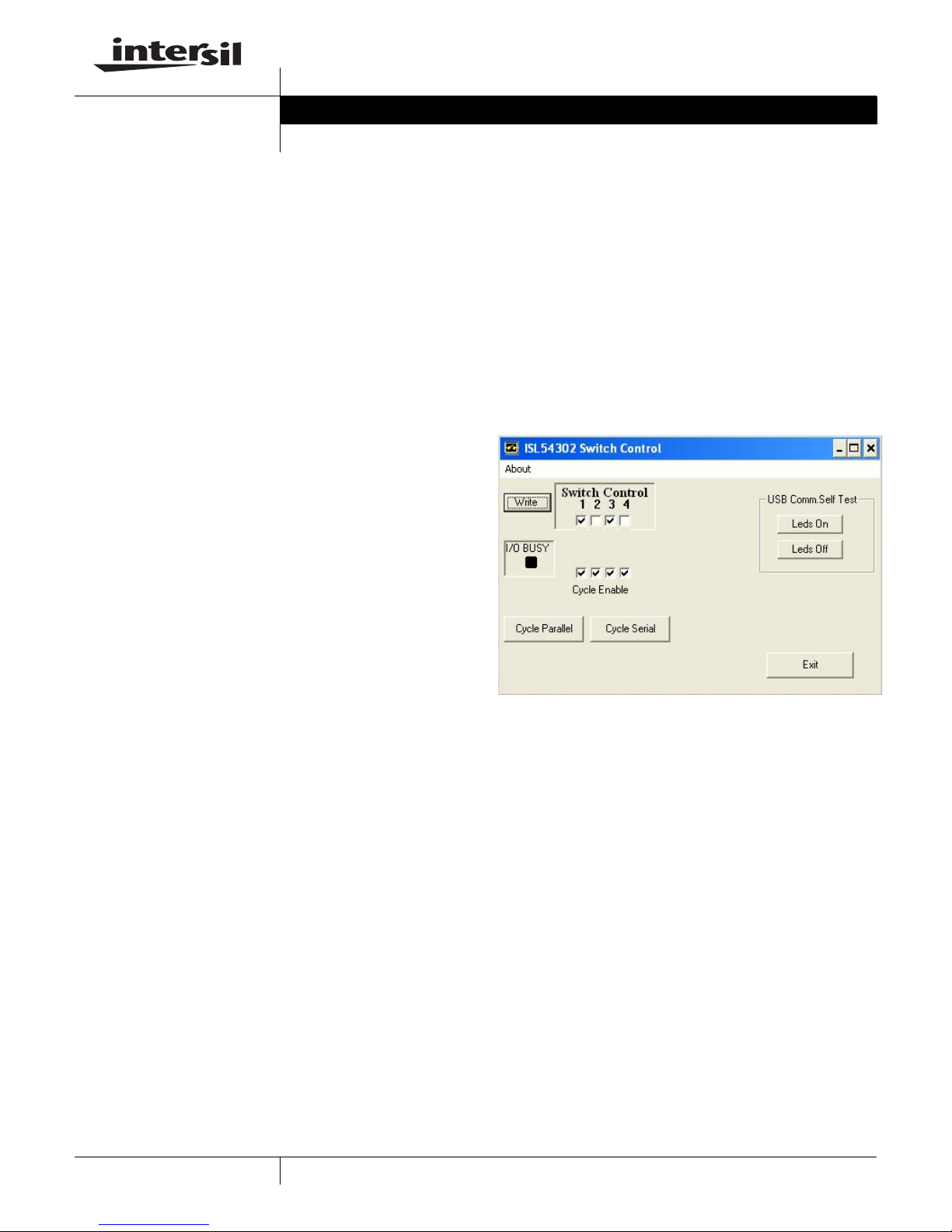
FIGURE 1. ISL54302 SWITCH CONTROL
Device Power Supply Banana Jacks
There are five banana jacks located on the edge of the
board.
• GND - the reference for all supplies always 0Vs
• VSS - the negative switch operating range (-3V to 0V)
• VDD - digital logic supply, always VSS + 3V
• VLOGIC - digital interface reference always 3V
• VPLUS - Positive switch operation range, 5V to 9V
Apply these voltages in the order detailed in the device
specification.
Test Setup Voltages
The user may wish to adopt the procedure outlined in the
“Initial Power-Up” section on page 2.
Once installation is complete, connect the USB cable. You
will receive audio notice that the new device is ready for use.
Once this occurs, double click on the ISL54302 application.
The operator interface screen will appear on your desktop.
1
CAUTION: These devices are sensitive to electrostatic discharge; follow proper IC Handling Procedures.
1-888-INTERSIL or 1-888-468-3774
| Intersil (and design) is a registered trademark of Intersil Americas Inc.
All other trademarks mentioned are the property of their respective owners.
Copyright Intersil Americas Inc. 2008. All Rights Reserved
Page 2

Application Note 1382
Electrical Specifications Evaluation Board Test, Typical
Current Drain
TEMP
PARAMETER
POWER SUPPLY CHARACTERISTICS
VPLUS Supply, I (Quiescent) 25 - 15 - µA
VSS Supply, I (Quiescent) 25 - 16 - µA
VDD Supply, I (Quiescent) 25 - 1 - µA
VLOGIC Internal Logic Supply,
I (Quiescent)
(°C) MIN TYP MAX UNITS
25 - 0 - µA
Scope Probe Connections
Another topic to cover before getting started is the evaluation
board physical connections for waveform observations. On
each schematic version, you will see a component with pins
designated as leadless scope probe connections. This is not
an active component but a dual pin header physically
designed to accommodate connection of Active/ Differential
Probes. This will minimize Ground Lead Inductance and
Capacitive Loading while make waveform observations.
However, the user must also be mindful of Max Voltage
Limitations when using these types of probes.
= LEADLESS SCOPE PROBE CONNECTION
BNC (Switch Contact) Connections
The evaluation board provides BNC connections for Switch
Contact A and Switch Contact B signals see Figures 2 and 3.
Since the ISL54302 is a quad switch device, there are eight
BNC connections to the evaluation board.
U12B
U12A
U11B
U11A
FIGURE 2. BNC CONNECTIONS FOR ALL SWITCH CONTACTS
U12B
U12A
U11B
U11A
U13A
U13B
U14A
U14B
U13A
U13B
U14A
U14B
Scope Probe Test Points (TP) are positioned across most
device pins and power supplies.
Initial Power-Up
Please refer to the device specifications found in the
FN6592 data sheet for power-up sequencing and current
requirements.
Test Setup Voltages
To get started, the user may wish to adopt the following
voltages which provide an analog switch range that is
rail-to-rail. With these conditions, the user needs only three
power supplies to get started.
• VSS = GND = 0V
• VDD = VLOGIC = 3V
• VPLUS = +6V to + 12V
The user can now open and close each switch via the
software by checking and unchecking the switch controls
and click the “Write” button.
Test Procedure
First Time Setup
SOFTWARE INSTALLATION AND BASIC
COMMUNICATIONS CHECK
1. Remove the USB cable; do not have Evaluation board
USB cable connected during software installation
2. Double click the provided installation file and follow the
instructions for installation
- Intersil_ISL54302_Installer.Exe.
3. When finished, exit the installation software.
4. Connect the USB cable between the Evaluation board
and your computer.
5. Run the Evaluation software. Start\ All Programs\Intersil\
ISL54302 Demo
6. Click the Led’s On and Led’s Off buttons and verify the
green and red LED’s on the Intersil USB board.
7. Exit the Software
2
March 18, 2008
Page 3
Application Note 1382
Test Procedure Fo r Each Board Under Test.
1. Connect USB cable between your computer and the
evaluation board.
2. Start the Evaluation Software
- “Start\All Programs\Intersil\ISL54302 Demo”
3. Verify the LED’s turn on and of f. (Click Led’s On/Led’s Of f
buttons on user screen.)
4. Apply power to the Evaluation Banana Jack,as specified
in the FN6592 (ISL54302 Data Sheet)
5. Verify approximate currents (Electrical Specifications
Table)
6. Place an ohm meter across each set of switch contacts
and open and close each switch with the software. Click
the associated switch check box and click “Write” button.
When the switch is closed, the resistance should be less
than 5Ω, and when open, it should be greater than 500k.
7. If all switches operate, board test is successful.
Schematic Information
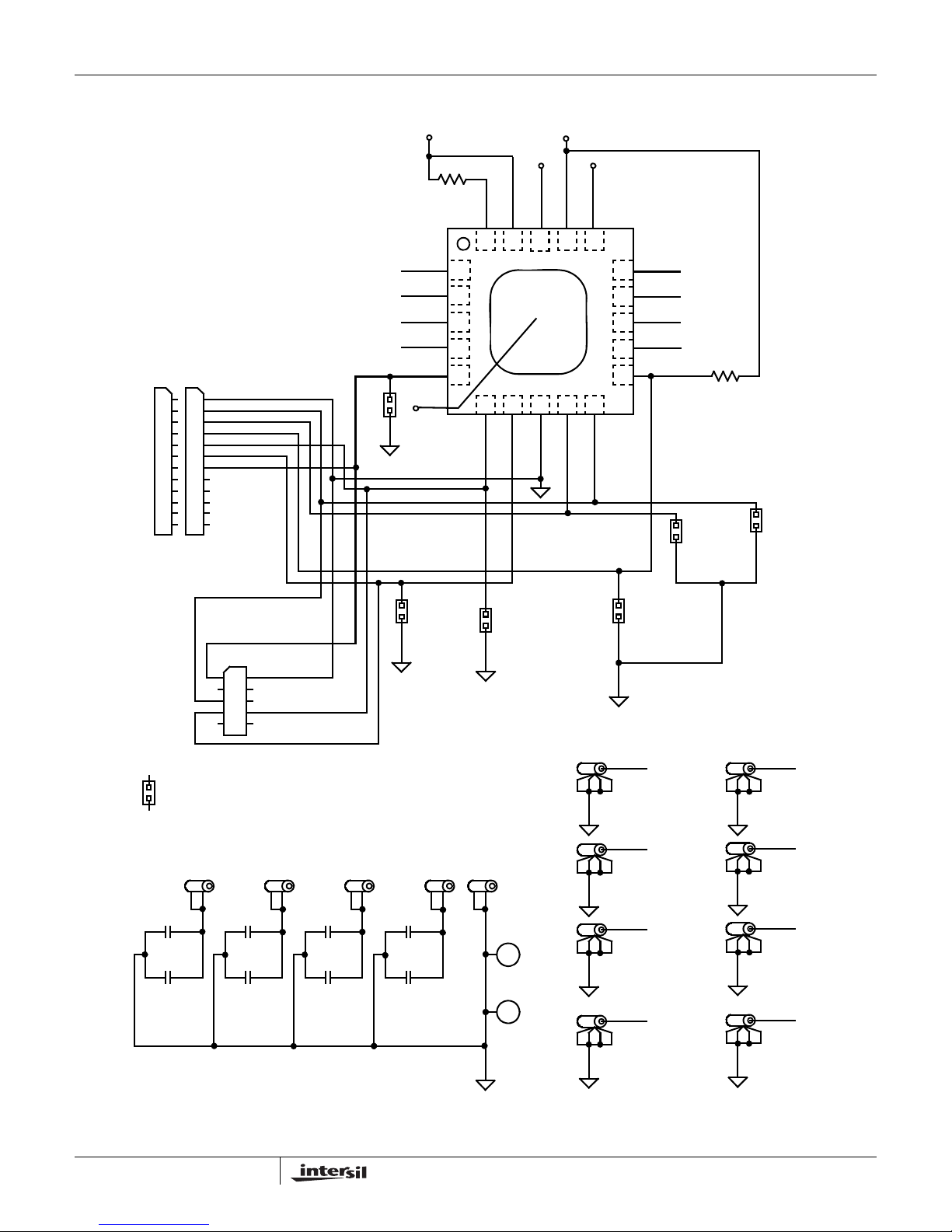
This evaluation board supports the ISL54301 and ISL54302.
In the case of the ISL54302, the Cheetah Connection is not
used. This also explains why there are scope probe test
points and connections made to pins designated as NC - “No
Connection” on the ISL54302 version of the Evaluation
board see Figure 4.
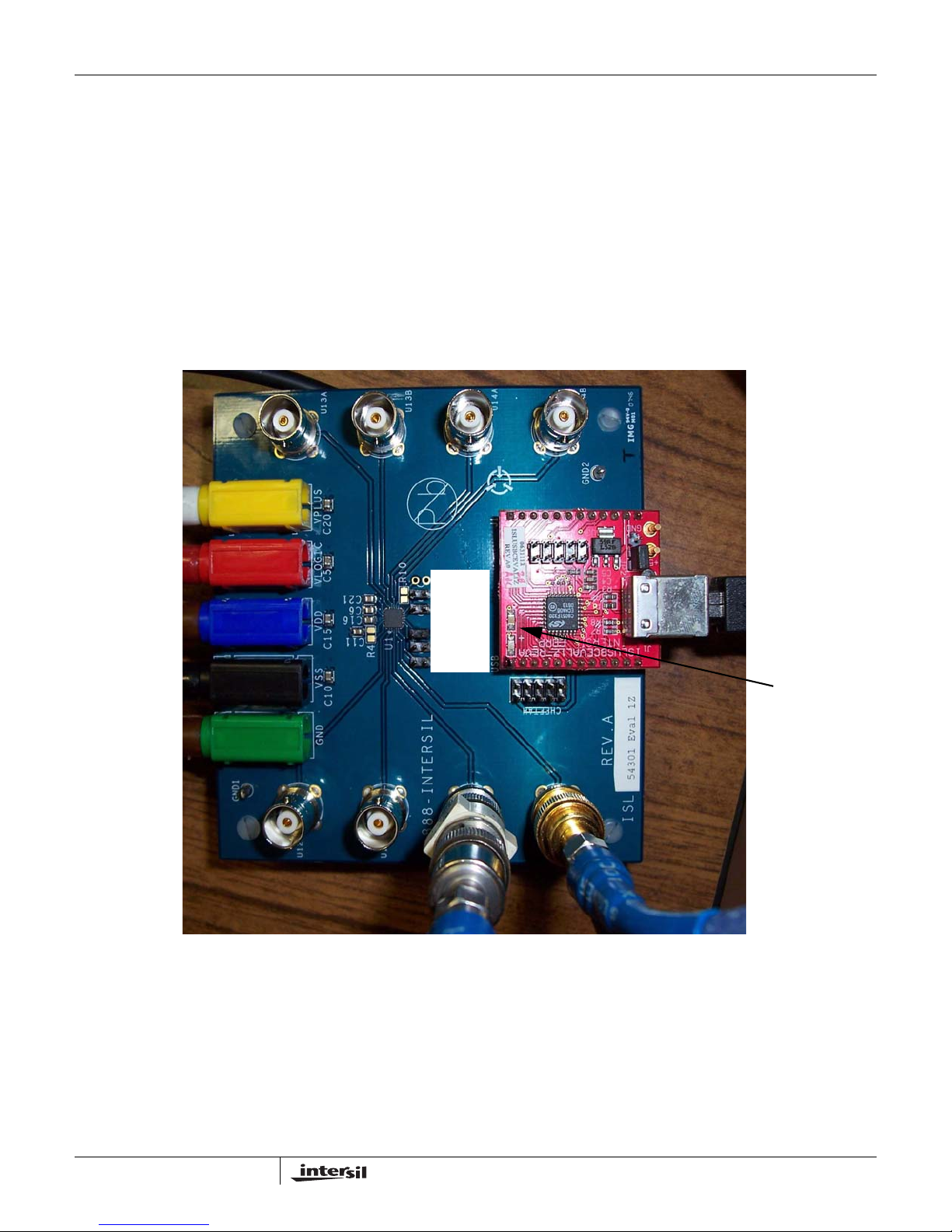
SCOPE
TEST
POINTS
FIGURE 3. ISL54302 EVAL BOARD (BNC CONNECTORS ALLOW FOR AC STIMULUS)
TEST LEDS
3
March 18, 2008
Page 4
Application Note 1382
Intersil USB Dongle Module
USBJ1
GND
1
1
2
3
4
5
6
7
8
9
10
11
12
2
3
4
5
6
7
8
9
10
11
12
SW-CTRL1
SW-CTRL2
P11-NC
SW-CTRL3
SW-CTRL4
CS-LATCH
U12B
U12A
U11B
U11A
CS_LATCH
CS_LATCH
VSS
VSS
DNP
2B
2A
1B
1A
R4
P20-NC
VSS
20 19 18 17 16
1
2
3
4
5
789106
SW-CTRL1
SW-CTRL2
VDD
VDD
GND
VLOGIC
VLOGIC
SW-CTRL3
VPLUS
VPLUS
SW-CTRL4
15
14
13
12
11
3A
3B
4A
4B
P11-NC
U13A
U13B
U14A
U14B
R10
DNP
SW-CTRL3
SW-CTRL4
CHEETAH
1
2
3
4
5
6
7
8
9
10
= SCOPE PROBE CONNECTION
VLOGIC
C5
4.7µF
C6
0.1µF
VSS
C10
4.7µF 4.7µF
C11
VDD VPLUS
C15
4.7µF
C16
SW-CTRL2
C20
C21
0.1µF0.1µF0.1µF
GND
SW-CTRL1
GND1
GND2
U12B
U12A
U11B
U11A
P11-NC
U12B
U12A
U11B
U11A
U13A
U13B
U14A
U14B
U13A
U13B
U14A
U14B
4
FIGURE 4. ISL54302 EVAL BOARD SCHEMATIC
March 18, 2008
Page 5
Application Note 1382
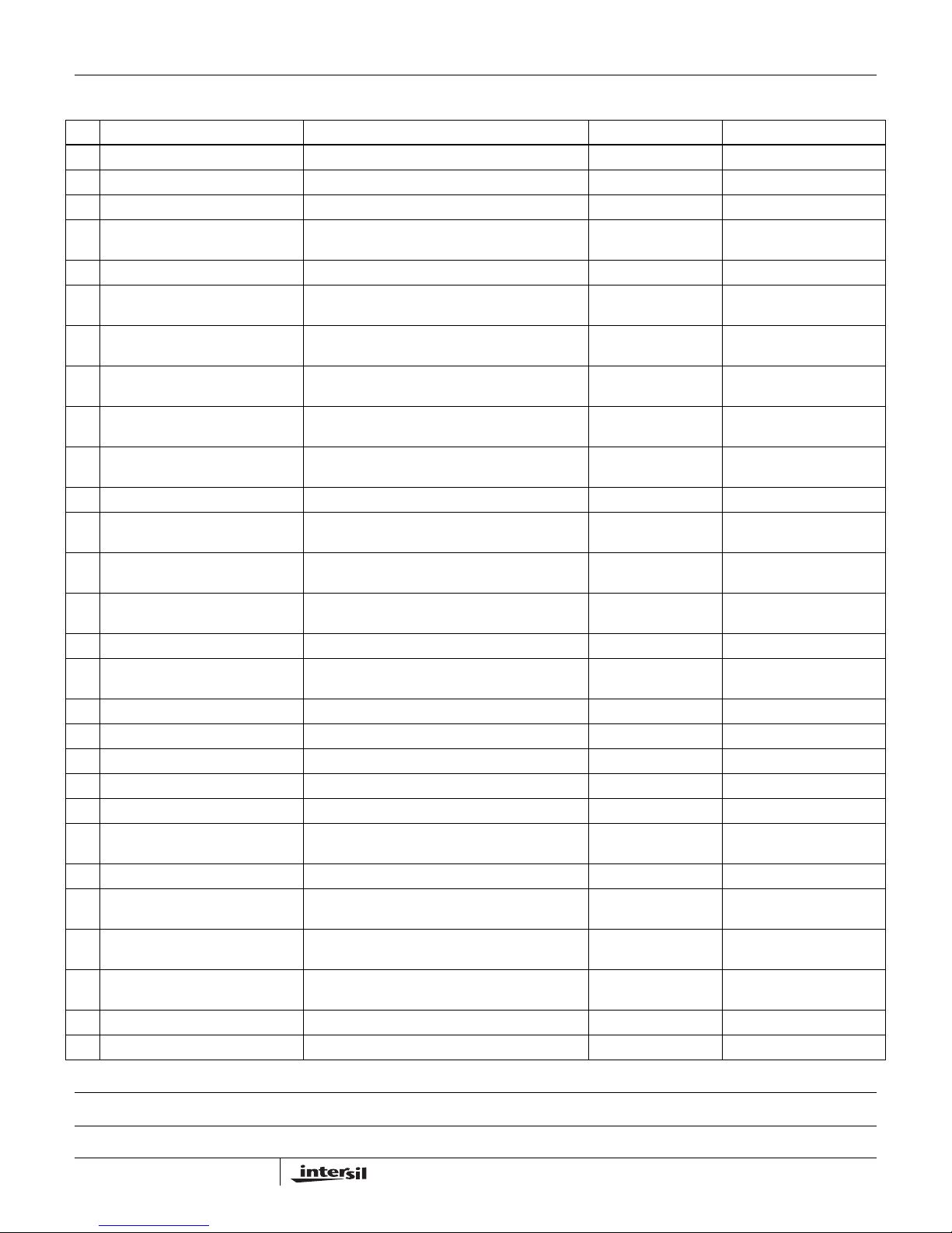
ISL54302EVAL1Z Bill of Materials
QTY REFERENCE DESIGNATOR DESCRIPTION MANUFACTURER MANUFACTURER PART
1 SEE LABEL-RENAME BOARD PWB-PCB, ISL5430XEVAL1Z, REVA, QFN, ROHS Intersil ISL5430XEVAL1ZREVAPCB
4 C6, C11, C16, C21 CAP, SMD, 0805, 0.1µF, 50V, 10%, X7R, ROHS MURATA GRM40X7R104K050AD
4 C5, C10, C15, C20 CAP, SMD, 0805, 4.7µF, 10V, 10%, X5R, ROHS AVX 0805ZD475KAT2A
8 U11A-U14A, U11B-U14B CONN-BNC, FEMALE, 50Ω, 4 POST VERTICAL
PC MOUNT, NICKEL W/GOLD CONTACT
2 GND1, GND2 CONN-MINI TEST PT, VERTICAL, BLK, ROHS KEYSTONE 5001
1 VSS CONN-PLUG, BANA-INSULSDRLESS, BLACK,
4mm, RA
1 VDD CONN-PLUG, BANA-INSUL-SDRLESS, BLUE,
4mm, ROHS, RA
1 GND CONN-PLUG, BANA-INSUL-SDRLESS, GREEN,
1 VLOGIC CONN-PLUG, BANA-INSUL-SDRLESS, RED,
1 VPLUS CONN-PLUG , BANA-INSUL-SDRLESS , YELLOW ,
1 CHEET AH CONN-HEADER, 2x5, BRKAWY 2x36, 2.54mm, ST BERG/FCI 67996-272
5 CLK-IN, CLK-OUT, DATA-IN,
CS_PULSE, DATA-OUT
2 J1, USB CONN-DEVICE SKT, 1x12, SIP STRIP-100PINS,
1 U1 IC-QUAD SPST ANALOG SWITCH, 20P, QFN,
0 R4, R10 RES, SMD, 0805, DNP-PLACE HOLDER, ROHS
4 Four corners SCREW, 4-40x1/2in, PAN, NYLON, PHILLIPS,
4 Four corners STANDOFF, 4-40x3/4in, F/F, HEX, NYLON KEYSTONE 1902D
1 Place assy in bag BAG, STATIC, 8x12, ZIP LOC INTERSIL D812(212403-014)
0 INTERRUPT DO NOT POPULATE OR PURCHASE
1 a) Use one long label for RELABELS LABEL, GENERIC
0 b) RELABEL: CLK-IN as S2_CTRL LABEL, GENERIC
0 c) RELABEL: CLK-OUT as
S3_CTRL
0 d) RELABEL: DATA-IN as S1_CTRL LABEL, GENERIC
0 e) RELABEL: CS_PULSE as
CS_LATCH
0 f) RELABEL: DATA-OUT as
S4_CTRL
1 RENAME PCB TO:
ISL54302EVAL1Z
1 LABEL, FOR SERIAL NUMBER AND BOM REV #
1 *INSTALL @ TEST PWB-ASSY, ISLUSBCEVAL1Z INTERSIL ISLUSBCEVAL1ZFG
4mm, ROHS, RA
4mm, RA
4mm, RA
CONN-HEADER, 1x2, RETENTIVE, 2.54mm, ST,
ROHS
072DIA, ROHS"
4X4, ROHS
ROHS
LABEL, GENERIC
LABEL, GENERIC
LABEL, GENERIC
LABEL, TO RENAME BRD
AMPHENOL 31-5329-52RFX
DELTRON 571-0100
DELTRON 571-0200
DELTRON 571-0400
DELTRON 571-0500
DELTRON 571-0700
BERG/FCI 69190-202HLF
ADVANCED
INTERCONNECTIONS
INTERSIL ISL54302IRZ
KSS100-33GG
Intersil Corporation reserves the right to make changes in circuit design, software and/or specifications at any time without notice. Accordingly, the reader is cautioned to
verify that the Application Note or Technical Brief is current before proceeding.
For information regarding Intersil Corporation and its products, see www.intersil.com
5
March 18, 2008
 Loading...