

Page 1
User’s Manual
ISL32740EVAL2Z
User’s Manual: Evaluation Board
Industrial Precision
Rev 1.00 Aug 2017
Page 2
USER’S MANUAL
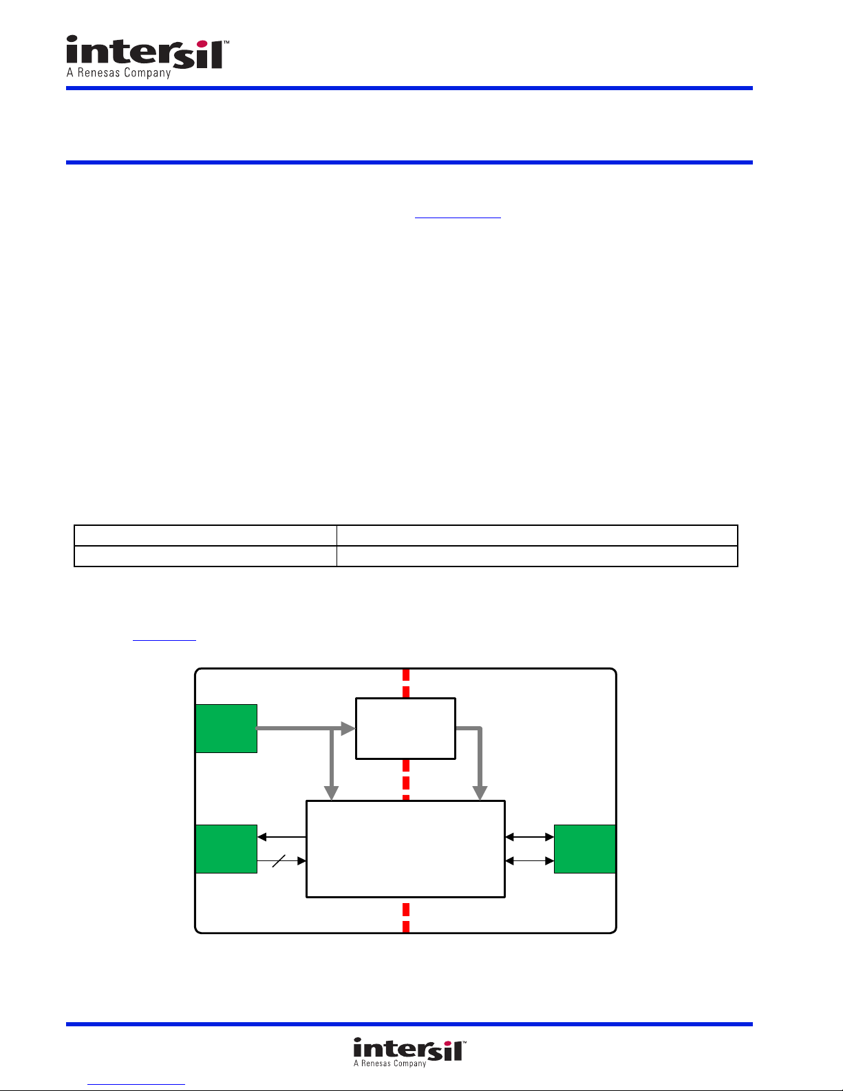
LOGIC
I/O
RS-485
I/O
3.3V
SUPPLY
J5J2
J1
ISL32740EIAZ
ISOLATED
PROFIBUS
TRANSCEIVER
ISOLATED
DC/DC
CONVERTER
5V
3
ISL32740EVAL2Z
Evaluation Board
1. Overview
The ISL32740EVAL2Z board enables the evaluation of the ISL32740EIAZ isolated, half-duplex PROFIBUS
transceiver in a typical bus node application, used in isolated industrial networks.
1.1 Key Features
• Industry’s smallest isolated PROFIBUS transceiver
• Drive capability of up to 160 bus transceivers
• Isolated 3.3V to 5V DC/DC converter with regulated output
• Small total device footprint of 183mm
1.2 Specifications
This board has been configured and optimized for the following operating conditions:
• Up to 40Mbps data rate
•V
= 3.3V
CC
1.3 Ordering Information
2
UG125
Rev.1.00
Aug 24, 2017
Part Number Description
ISL32740EVAL2Z ISL32740EIAZ evaluation board
1.4 Related Literature
• For a full list of related documents, visit our website
• ISL32740E
product page
UG125 Rev.1.00 Page 2 of 10
Aug 24, 2017
Figure 1. Block Diagram
Page 3
ISL32740EVAL2Z 2. Functional Description
2. Functional Description
The ISL32740E is an isolated, 40Mbps, half-duplex PROFIBUS transceiver. The device incorporates a patented refresh
circuit to maintain the correct output state with respect to data input. At power-up, the bus outputs follow the Truth Tables
The DE input should be held low during power-up to prevent false drive data pulses on the bus. This is accomplished by
connecting DE through a 10kΩ pull-down resistor to GND1.
This transceiver uses a differential input receiver for maximum noise immunity and common-mode rejection. Input
sensitivity is ±200mV, as required by the RS-485 specification.
The receiver input resistance meets the PROFIBUS “Unit Load” (UL) requirement of 54kΩ minimum. The receiver
includes a “fail-safe if open” function that ensures a high-level receiver output if the receiver inputs are unconnected
(floating). The receiver output is tri-statable through the active low RE
input.
The PROFIBUS driver is a differential output device that delivers at least 2.1V across a 54Ω purely differential load.
The driver features low propagation delay skew to maximize bit width and to minimize EMI.
The driver in the ISL32740E is tri-statable using the active high DE input. The outputs of the ISL32740E driver are not
slew rate limited, so faster output transition times allow data rates of at least 40Mbps.
Important Notice:
For convenience, an isolated DC/DC converter is used to provide the power supply across the isolation barrier. Its
isolation ratings, however, are lower than those of the transceiver. Therefore, ensure that the ground potential
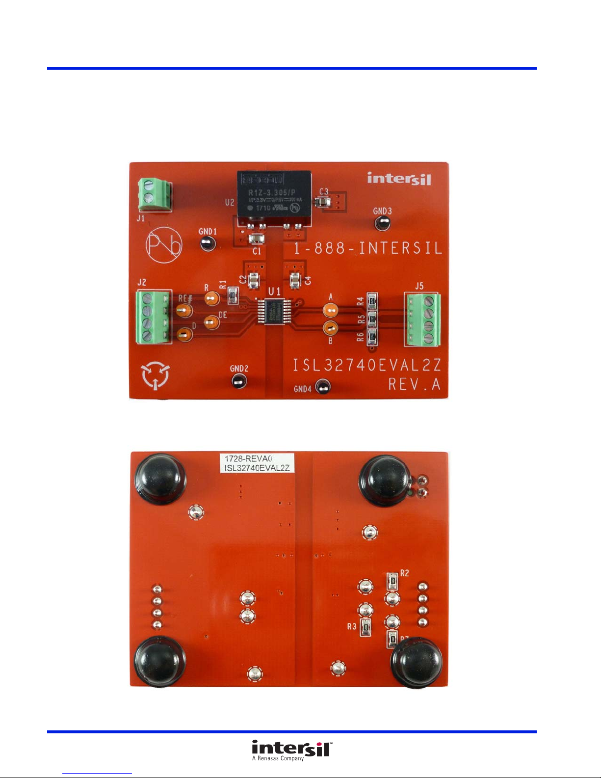
difference between the left side (GND1, GND2) and the right side (GND3, GND4) of the board remain below 50VAC
(see Figure 2 on page 4
).
.
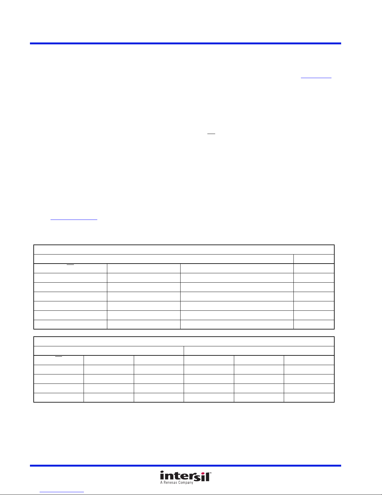
2.1 Truth Tables
Receiving
Inputs Outputs
RE
00 V
0 0 -0.05 > V
00 V
0 0 Inputs Open/Shorted 1
1 1 X High-Z
1 0 X High-Z*
Inputs Outputs
RE
X11101
X10110
0 0 X 0 High-Z High-Z
1 0 X 0 High-Z* High-Z*
Note: *Transceiver shutdown mode.
DE D ISODE B A
DE A-B RO
≥ -0.05V 1
AB
> -0.2V Undetermined
AB
≤ -0.2V 0
AB
Transmitting
UG125 Rev.1.00 Page 3 of 10
Aug 24, 2017
Page 4
ISL32740EVAL2Z 3. PCB Layout Guidelines
3. PCB Layout Guidelines
Both supplies, V
be placed as close as possible to the supply pins.
DD1
and V
, must be bypassed with 100nF ceramic capacitors. For proper operation, these should
DD2
3.1 ISL32740EVAL2Z Evaluation Board
Figure 2. Top Side
UG125 Rev.1.00 Page 4 of 10
Aug 24, 2017
Figure 3. Bottom Side
Page 5
UG125 Rev.1.00 Page 5 of 10
Aug 24, 2017
ISL32740EVAL2Z 3. PCB Layout Guidelines
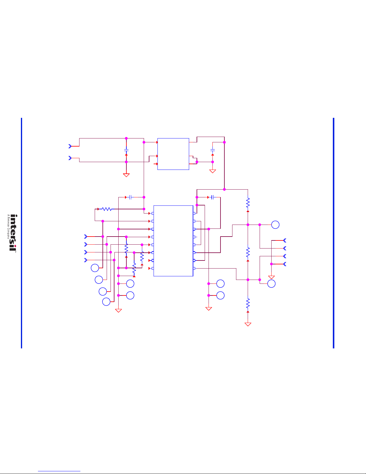
3.2 ISL32740EVAL2Z Circuit Schematic
Figure 4. Schematic
ISL32740EIAZ
A
A
C3
10UF
DE
A
C2
0.1UF
J1-4
1
GND4
D
J5-4
1
R7
10K
J1-3
2
GND3
R1
10K
J5-3
2
R3
10K
J2-4
1
1
2
4
5
6
7
8
3
9
10
11
12
13
14
15
16
U1
1
2
3
4
5
6
7
8 9
10
11
12
13
14
15
16
J5-2
3
J2-3
2
R6
549
R2
10K
J5-1
4
+VOUT
-VOUT
NC
-VIN
-VOUT
+VIN
U2
R1Z-3.305/P
1
2
4
5
7
10
J2-2
3
R5
133
J2-1
4
R4
549
C1
10UF
C4
0.1UF
R
B
GND2
RE#
GND1
UNNAMED_1_QSOP16_I1_PIN12
UNNAMED_1_QSOP16_I1_PIN6
UNNAMED_1_R1Z_I40_2
UNNAMED_1_SMRES_I28_B
UNNAMED_1_SMRES_I29_B
UNNAMED_1_SMRES_I2_A
UNNAMED_1_SMRES_I30_B
UNNAMED_1_SMRES_I3_A
UNNAMED_1_R1Z_I40_7
Page 6
ISL32740EVAL2Z 3. PCB Layout Guidelines
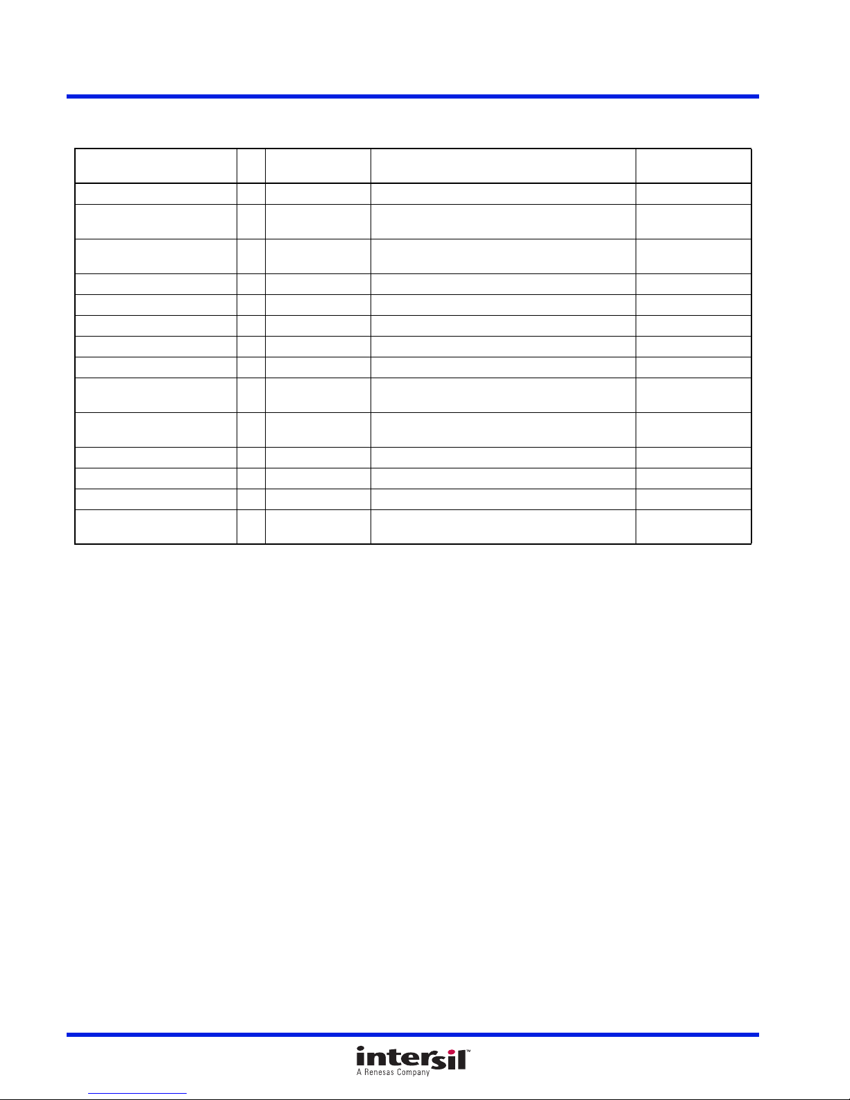
3.3 Bill of Materials
Manufacturer
Part Qty
ISL32740EVAL2ZREVAPCB 1 PWB-PCB, ISL32740EVAL2Z, REVA, ROHS IMAGINEERING INC
ISL32740EIAZ 1 U1 ISOLATED, 40MBPS, HALF-DUPLEX PROFIBUS
R1Z-3.305/P 1 U2 ISOLATED 3.3V-TO-5V DC/DC CONVERTER
CR0805-8W-1002FT 4 R1-R3, R7 RES, SMD, 0805, 10k, 1/8W, 1%, TF, ROHS VENKEL
RK73H2AT1330F 1 R5 RES, SMD, 0805, 133Ω, 1/8W, 1%, TF, ROHS KOA
RC0805FR-07549RL 2 R4, R6 RES, SMD, 0805, 549Ω, 1/8W, 1%, TF, ROHS YAG EO
C0805X5R160-106KNE 2 C1, C3 CAP, SMD, 0805, 10µF, 16V, 10%, X5R, ROHS VENKEL
ECJ-2VB1E104K 2 C2, C4 CAP, SMD, 0805, 0.1µF, 25V, 10%, X7R, ROHS PANASONIC
1725656 1 J1 CONN-TERMINAL BLK, TH, 2P, 6A, 125V,
1725672 2 J2, J5 CONN-TERMINAL BLOCK, 4POS, 0.1, 26-20AWG,
5001 4 GND1 - GND4 CONN-MINI TEST PT, VERTICAL, BLK, ROHS KEYSTONE
5003 6 A, B, D, R, DE, RE# CONN-MINI TEST POINT, VERTICAL, ORG, ROHS KEYSTONE
S-2261 1 Place assy in bag BAG, STATIC, 4x6, ZIPLOC, ROHS ULINE
LABEL-DATE CODE 1 AFFIX TO BACK
Reference
Designator Description Manufacturer
Intersil
TRANSCEIVER, ROHS
RECOM-POWER
PHOENIX CONTACT
PHOENIX CONTACT
Intersil
OF PCB
WITH REGULATED OUTPUT, ROHS
20-30AWG, 2.54mm, ROHS
63V, 6A, ROHS
LABEL-DATE CODE_LINE 1: YRWK/REV#, LINE 2:
BOM NAME
UG125 Rev.1.00 Page 6 of 10
Aug 24, 2017
Page 7
ISL32740EVAL2Z 3. PCB Layout Guidelines
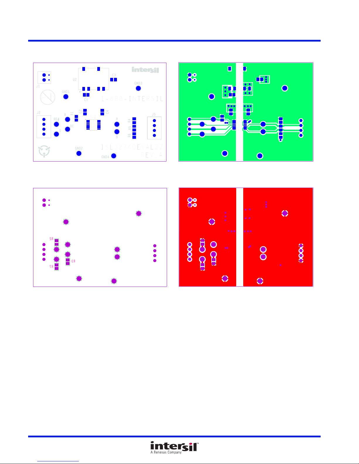
3.4 Board Layout
Figure 5. Silkscreen Top Figure 6. Top Layer
Figure 7. Silkscreen Bottom
UG125 Rev.1.00 Page 7 of 10
Aug 24, 2017
Figure 8. Bottom Layer
Page 8
ISL32740EVAL2Z 3. PCB Layout Guidelines
TIME: 10ns/DIV
SIGNAL: 2V/DIV
DI
A
B
TIME: 10ns/DIV
SIGNAL: 2V/DIV
RO
A
B
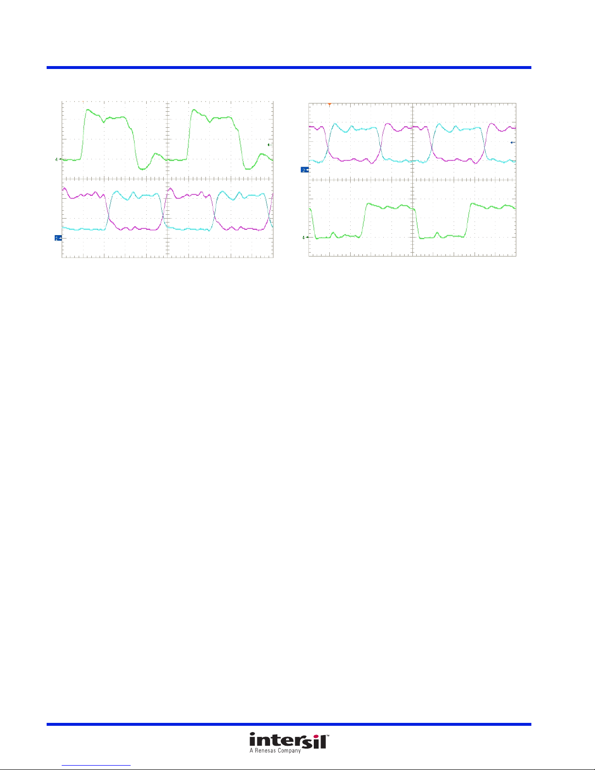
3.5 Typical Performance Curves
Figure 9. Transmit Mode
Figure 10. Receive Mode
UG125 Rev.1.00 Page 8 of 10
Aug 24, 2017
Page 9
ISL32740EVAL2Z 4. Revision History
4. Revision History
Rev. Date Description
1.00 Aug 24, 2017 Updated truth tables.
0.00 Jul 20, 2017 Initial release
© Copyright Intersil Americas LLC 2017. All Rights Reserved.
All trademarks and registered trademarks are the property of their respective owners.
Intersil Corporation reserves the right to make changes in circuit design, software and/or specifications at any time without notice. Accordingly, the
reader is cautioned to verify that the document is current before proceeding.
For information regarding Intersil Corporation and its products, see www.intersil.com
UG125 Rev.1.00 Page 9 of 10
Aug 24, 2017
Page 10
ISL32740EVAL2Z
UG125
 Loading...