


Interroll Portec
SG/SL Belt Power Curve
Conveyor Location: _______________________________
Model Number: __________________________________
Serial Number: ___________________________________
Year of Manufacture: ______________________________
Interroll Engineering West, Inc.
(formerly known as PORTEC)
One Forge Road |
Tel.: |
+1(719) 275-7471 |
Cañon City, CO 81212 |
Fax: |
+1(719) 269-3750 |
USA |
E-mail: |
cc.sales@interroll.com |
|
Website:www.interroll.com |
|
8/2015
PS249/PS271

Page 2 IEW – Portec, Inc. |
|
TABLE OF CONTENTS |
|
|
Page |
Section 1. |
|
Tool Requirements.................................................................................................... |
3 |
Section 2. |
|
Safety Precautions.................................................................................................... |
4 |
Section 3 |
|
Portec Belt Curve in a System Layout...................................................................... |
6 |
Section 4. |
|
Unpacking the crate.................................................................................................. |
7 |
Section 5. |
|
Belt Curve Installation Instructions............................................................................ |
8 |
Section 6. |
|
Floor Supports—Installation Instructions.................................................................. |
9 |
Section 6A. |
|
Ceiling Hangers—Installation Instructions ........................................................ |
11 |
Section 7. |
|
Sideguard—Installation Instructions ....................................................................... |
12 |
Section 8. |
|
Solid Metal Underguarding Installation Instructions ............................................... |
13 |
Section 9. |
|
Shaft-Mounted Gear motor Installation Instructions ............................................... |
14 |
Section 10. |
|
Inspection Checklist................................................................................................ |
16 |
Section 11. |
|
Preventive Maintenance ......................................................................................... |
17 |
Section 11A. |
|
Inspection and Service Schedule........................................................................ |
18 |
Section 11B. |
|
Inside Radius Belt Tension Adjustment.............................................................. |
19 |
Section 11C. |
|
Belt Chain Tension Adjustment........................................................................... |
19 |
Section 11D. |
|
Belt Chain Sprocket Alignment........................................................................... |
20 |
Section 11E. |
|
Lubrication – Chain Guide Strips........................................................................ |
21 |
Section 11F. |
|
End Roll Alignment ............................................................................................. |
22 |
Section 11G. |
|
Taper-Lock Bushings in End Rolls and Sprockets.............................................. |
23 |
Section 12. |
|
Replacement of Belts with Laced Seams ............................................................... |
24 |
Section 13. |
|
Replacement of Belts with Endless Seams ............................................................ |
27 |
Section 14. |
|
Belt Attachment-Link Replacement......................................................................... |
31 |
Section 15. |
|
Replacing Belt Segment ......................................................................................... |
33 |
Section 16. |
|
Belt Chain Guide Replacement............................................................................... |
36 |
Section 16A. |
|
Upper Guide Replacement ................................................................................. |
37 |
Section 16B. |
|
Lower Guide Replacement ................................................................................. |
38 |
Section 17. |
|
Troubleshooting Guide............................................................................................ |
39 |
Section 18. |
|
Recommended Spare Parts List (RSPL) ............................................................... |
40 |
Section 19. |
|
Spare Parts Diagram............................................................................................... |
41 |
Section 19A. |
|
Spare Parts List....................................................................................................... |
42 |

Section 1: Tool Requirements |
|
IEW - Portec, Inc. Page 3 |
Belt power curve
Tool list for installation, maintenance and belt replacement
Tool |
Used For |
|
|
10 mm, 15 mm, 17 mm or 9/16” wrench |
Bearing tensioners |
|
|
15 mm, 1/2” or 9/16” wrench or socket |
Bearing housing 1-3/16” (30 mm) shaft or smaller |
|
|
18 mm or 3/4” wrench or socket |
Bearing housing 1-7/16” (35 mm) shaft or larger |
|
|
13 mm or 1/2” wrench or socket |
Chain cover—Sideguards—End caps |
|
|
13 mm or 1/2” wrench or socket |
Return guide extrusion |
|
|
15 mm, 17 mm, 9/16” or 3/4” wrenches |
Floor supports |
5/16” Allen wrench (2” sq. tubing connector) |
|
|
|
Socket wrench set |
Drive and mount |
|
|
Small powered drill with 1/8” (3.2 mm), |
Upper chain guide strips |
5/64” (1.98mm) and 7/64” (2.8 mm) drill bits and |
|
rivet gun with 1/8” (2.8 mm) rivets |
|
|
|
5/32” (4 mm) Allen wrench |
End rolls |
|
|
3/16” (5 mm) Allen wrench |
Sprocket set screws |
|
|
5/32” (4 mm) Allen wrench |
Bearing set screws 1-7/16” (35mm) shaft or larger |
|
|
1/8” (3 mm) Allen wrench |
Bearing set screws 1-3/16” (30mm) shaft or smaller |
|
|
3/32” (2.5 mm) Allen wrench |
Return wheels |
|
|
Electricians nut driver set or adjustable wrench |
Electrical motor connections |
|
|
Flat blade screwdriver |
Chain guide strips |
|
|
Needle nose pliers and side cutters |
Conveyor belt lacing |
|
|
Rubber mallet |
Chain tension adjustment |
|
|
Grease gun |
Lubricate chain |
|
|
Seam lacing machine |
Seam lacing |
|
|
Chain breaker tool |
Attachment links |
Note: Only trained personnel should perform all required work on the conveyor to prevent any danger to the operators or other persons, and to prevent damage to the conveyor.
WARNING: Disconnect and lock-out power before performing any installation or maintenance procedures. All guards must be in place before startup of con-
Note: Do not lift a conveyor by the drive shaft extension. This can cause damage, such as a bent shaft.
WARNING: Observe all safety precautions when working under hoisting equipment.
Note: To ensure proper installation and safety, only qualified mechanics and electricians should install conveyors.

|
Section 2: Safety Precautions |
Page 4 IEW – Portec, Inc. |
Portec does not install conveyors, therefore, it is the responsibility of the contractor, installer, owner and user to install, maintain and operate the conveyor, components and conveyor assemblies in such a manner as to comply with all national, state and local laws and ordinances, including all National Occupational Safety and Health Codes and applicable Lockout/Tagout codes.
In order to avoid an unsafe or hazardous condition, the conveyors or parts must be installed and operated in accordance with the following minimum provisions.
1.Conveyors shall not be operated unless all covers and/or guards for the conveyor and drive unit are in place. If the conveyor is to be opened for inspection cleaning, maintenance or observation, the electric power to the motor driving the conveyor must be LOCKED OUT/TAGGED OUT in such a manner that the conveyor cannot be restarted by anyone; however remote from the area, until conveyor cover or guards and drive guards have been properly replaced.
2.If the conveyor must have an open housing as a condition of its use and application, the entire conveyor is then to be guarded by a railing or fence in accordance with the current National Safety Standard.
3.Do not attempt any maintenance or repairs of the conveyor until power has been LOCKED OUT/TAGGED OUT.
4.Always operate conveyor in accordance with these instructions and those contained on the caution labels affixed to the equipment.
5.Do not place hands, feet, or any part of your body, in the conveyor.
6.Never climb, sit, stand or work from a conveyor, or walk on conveyor covers or guards. When requested by the customer, some conveyors are equipped with safety handrails, which are to be used for maintenance purposes only. If the safety handrails are necessary for maintenance, they are to be used only after ensuring that the power has been LOCKED OUT/TAGGED OUT. The safety handrails must be removed before restoring power to the conveyor.
7.Do not use conveyor for any purpose other than that for which it was intended.
8.Do not poke or prod material into the conveyor with a bar or stick inserted through the openings.
9.Keep the area around conveyor drive and control station free of debris and obstacles.
10.Eliminate all sources of stored energy (materials or devices that could cause conveyor components to move without power applied) before opening the conveyor.
11.Do not attempt to clear a jammed conveyor until power has been LOCKED OUT/TAGGED OUT.
12.Do not attempt field modification of conveyor or components without prior approval of Portec.
13.Conveyors are not normally manufactured or designed to handle materials that are hazardous to personnel. These hazardous materials include those that are explosive, flammable, toxic or otherwise dangerous to personnel. Conveyors may be designed to handle these materials. If hazardous materials are to be conveyed, Portec should be consulted prior to any modifications.
14.When two or more conveyors are interfaced or joined together, make sure there is adequate guarding, pinch point protection and safety devices.
15.Only trained operators should be permitted to operate and maintain conveyors. Training needs to include instruction in operation under normal conditions and emergency conditions.
16.All starting and stopping devices should be clearly marked and the immediate area kept clear of obstructions to permit ready access.
17.The areas around loading and unloading points should be kept clear of any obstructions.
18.A person should NOT BE PERMITTED TO RIDE on any conveyor not specifically designed and approved to convey people.
19.Workers working around or operating conveyors should be shown the location of the starting and stopping devices and instructed how to use them to stop the conveyor in an emergency.

IEW - Portec, Inc. Page 5
20.Do not use a conveyor for any purpose other than that for which it was intended. A conveyor should only be used to transport material it is capable of handling safely. Under no circumstances should safety guarding or labels attached to the conveyor be altered or removed without written permission from the owner/manufacturer. If the labels attached to the equipment become illegible, order replacement warning labels from Portec.
22.Routine inspections and Preventive and Corrective maintenance programs should be conducted to ensure that all safety features and devices are in place and functioning properly.
23.Employees should be alerted to the potential hazard of entanglement in conveyors caused by items such as long hair, loose clothing, and jewelry.
24.As a general rule, conveyors should not be cleaned while in operation. Where proper cleaning requires the conveyor to be in motion and a hazard exists, personnel should be made aware of all associated hazards as indicted above and take proper precautions.
Additional Safety Notes:
Disconnecting and locking out the power to the motor driving the unit provides the only real protection against injury. Secondary safety devices are available; however, the decision as to their need and the type required must be made by the ownerassembler as Portec has no information regarding plant wiring, plant environment, the interlocking of the conveyor with other equipment, extent of plant automation, etc. Other devices should not be used as a substitute for locking out the power prior to removing guards or covers. We caution that use of the secondary devices may cause employees to develop a false sense of security and fail to lock out power before removing covers or guards. This could result in a serious injury should the secondary device fail or malfunction.
Electrical controls, machinery guards, railings, walkways, arrangement of installation, training of personnel, etc., are necessary ingredients for a safe working place. It is the responsibility of the contractor, installer, owner and user to supplement the materials and services provided by Portec to make the conveyor installation comply with the law and accepted standards.
Examples of Safety Labels used on conveyors:
|
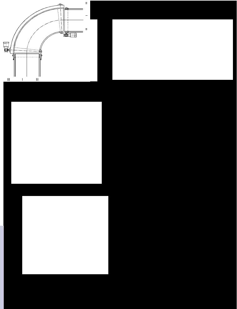
Section 3: Portec Belt Curve in a System Layout |
Page 6 IEW – Portec, Inc. |
The objective is to get the sideguards to match up. The "Conveying Width" on a belt curve is equivalent to the "Between Sideguard Width" on a straight belt conveyor. The outside radius frame, chain cover and both sideguards on the belt curve extend 3/8” (9.5 mm) past the true angle. The inside radius frame length matches
the true angle.
Centerline radius
3.5” (89 mm) |
Conveying width |
Inside |
|
|
radius |
Centerline radius of belt curve + 3/8” (9.5mm)
Centerline radius of belt curve + 3/8” (9.5mm)
The ends of two straight conveyors should be positioned so they are both the same distance from the centerline intersection point as the "Centerline Radius" of the belt curve plus 3/8” (9.5 mm). The outside arc of the two belt centerlines should be identical to the arc of the belt curve.
Centerline
When the following factors are correct, the belt curve will fit perfectly:
1."Conveying Width" of the belt curve is equal to the "Between Sideguard Width" of the straight conveyors.
2.The arc of the belt curve is the same as the outside arc of the two straight conveyor centerlines.
3.The two straight conveyors are set back the same distance from the belt centerline intersection as the "Centerline Radius" of the belt curve plus 3/8” (9.5 mm).
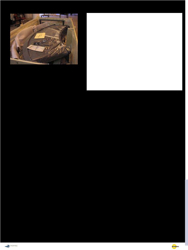
Section 4: Unpacking the crate |
|
IEW - Portec, Inc. Page 7 |
Belt curves are normally built with a one-piece frame. Large-sized belt curves may be built in multiple sections and will require additional assembly during installation.
Notes:
Minor inspection is suggested during uncrating of a conveyor. Contact the shipping carrier immediately if shipping damage is suspected. Please carefully check the crate or skid to ensure all parts are removed before beginning installation.
If floor supports, sideguards (12” (305mm) or higher), or drive unit are provided by Portec, they are normally removed from the belt curve for shipping. The brackets or holes for mounting to the frame are provided. All hardware and fasteners for mounting are included.

Page 8 IEW – Portec, Inc.
3/4-1” (19-25 mm)
Section 5: Belt Curve Installation Instructions
1.Position the conveyor between the adjoining conveyors.
2.Attach floor supports or ceiling hangers under the conveyor. See Section 5 (Floor Supports) or Section 6 (Ceiling Hangers) for instructions.
3.Attach sideguards (if required). See Section 7 for instructions.
4.Install underguarding. See Section 8 for instructions.
5.Install drive unit. See Section 9 for Shaft-Mount Gearmotor Installation Instructions.
6.Visually inspect:
Motors
Sideguard to belt clearance
Belt tension
Drive mounting and alignment
Return wheel assembly
7.Connect power to the drive unit and test run to assure the proper belt movement direction.
During the initial 40-hour run-in period, listen for any noises that may indicate that something is out of alignment or loose in the conveyor.
Note: The belt curve end rolls are adjusted at the factory so there is an approximately 3/4-1” (19-25 mm) gap between the belt on the end roll of the curve and the adjoining conveyor frame. The gap between end rolls can be less than 3/4” (19 mm) if the end roll on the adjoining conveyor is extended beyond the conveyor frame.

Section 6: Floor Supports—Installation Instructions |
|
IEW - Portec, Inc. Page 9 |
Low Floor Support
Upper support leg
Lower support leg |
Support crossmember |
High Floor Support with X-Bracing
Upper support leg |
Support crossmember |
Assembly Instructions for Adjustable Height Supports
The support assemblies are adjustable for height and width using slots and holes.
1.Assemble the upper and lower support legs. Ensure that the support leg is the proper length before tightening the fasteners. Two heavy duty flange bolts and nuts must be used on each vertical leg to ensure support of the conveyor.
2.Assemble the support crossmembers using two heavy duty flange bolts and flange nuts. Ensure that the support crossmembers are the proper length before tightening the fasteners.
3.Assemble the support assembly using two legs and one or two crossmembers.
4.High supports may require an X-brace. Attach the X- brace to both the vertical legs and the crossmembers.
Lower support leg |
Support X-Bracing |
|
|
|
|

Page 10 IEW – Portec,
Installation Instructions for Adjustable Height Floor
Supports
1.Stand the assembled floor supports under the conveyor. Attach to the bottom flange of the conveyor. Leave the fasteners slightly loose.
2.Lower the conveyor into position with the support feet on the floor.
3.Check to ensure that the conveyor is level across and along the belt surface (end to end). It is acceptable for one end to be slightly higher than the opposite end, but the conveyor frame must not be twisted.
4.Check to ensure that the support legs are vertical.
5.Check the conveyor height in relation to the adjoining conveyors. To make slight adjustments to the height, loosen the bolts that hold the upper and lower legs together. For large height adjustments, remove the bolts that hold the upper and lower legs together. Slide the upper and lower legs until the leg is at the required height and install and tighten the bolts.
6.Tighten all fasteners in the support legs, including the fasteners that attach the support legs to the conveyor.
7.Fasten the conveyor to the floor using floor anchors.
|
|
|
Section 6A: Ceiling Hangers—Installation Instructions |
IEW - Portec, Inc. Page 11 |
|
WARNING: Observe all safety precautions when working under hoisting equipment.
1.Raise the conveyor and attach the ceiling hanger supports to the bottom flange of the conveyor.
2.Move the conveyor to the required position.
3.Hang threaded rods securely from an overhead structure. Install jam nut near the bottom end of each threaded rod.
4.Insert the ends of the threaded rods through the predrilled holes in the ceiling hangers and install a second jam nut on each rod under the support hangers.
5.Adjust the jam nuts until the conveyor is positioned correctly at the right elevation. Check to ensure that the conveyor is level across and along the belt surface (end to end). It is acceptable for one end to b slightly higher than the opposite end, but the conveyor frame must not be twisted. Tighten all jam nuts to secure the conveyor in position.
Standard ceiling support hanger extends 4” (100 mm) past the conveyor frame. The hole center for the hanger rod is 2.75” (70 mm) from the frame.
A ceiling support hanger under a drive unit is longer. The support hanger extends 4” (100 mm) beyond the drive shaft extension. The hole center for the hanger rod is 70 mm beyond the end of the drive shaft extension.
The standard hole diameter for the hanger rod is 3/4” (20 mm).
2.75” |
2.75” |
|
(70 mm) |
||
(70 mm) |
||
|
3/4” (20 mm) diameter hole |
3/4” (20 mm) diameter hole. |
|
4” (100 mm) |
4” (100 mm) |
|
|
|
|

|
Section 7: Sideguard—Installation Instructions |
Page 12 IEW – Portec, |
Sideguards for Portec curves are designed for quick, easy installation. Sideguards are installed at the factory prior to shipment. The sideguards may be removed for shipment. Portec uses cage nut inserts and slots to avoid loss of loose fasteners and to make installation and adjustment fast and easy.
1.Begin installation of the inside radius sideguard by loosening the bolts on the inside radius side frame. The bolts should be backed out 1/8-3/16” (3-5 mm).
2.Place the inside radius sideguard against the inside radius curved side frame above the loosened bolts. Align the slots in the lower edge of the sideguard with the bolts and lower the sideguard down onto the bolts.
3.Align the sideguard so it extends past the frame by an equal amount on each end of the side frame. The inside radius sideguard is designed to extend 3/8” (10 mm) past the end of the inside radius frame. Tighten the bolts.
4.Place the outside radius sideguard on top of the outside radius curved chain cover. Align the slots in the lower mounting flange with the studs in the top of the chain cover.
5.Align the outside radius sideguard so the end is flush with the end of the chain cover.
6.Fasten the sideguard to the chain cover.
7.Check the clearance between the bottom of the sideguard and the top of the conveyor belt. There should be 1/8-3/16” (3-5 mm) of clearance. Do no allow the sideguard to contact the belt.
8.If the sideguards are equipped with end flanges, attach the end flanges to the end flanges on the ad-
WARNING: Sideguards are not designed to support any weight from above. If the outside radius sideguard is pushed down, it may contact and damage the conveyor belt. It is extremely dangerous to temporarily support a conveyor by hanging it from its sideguards. The sideguards can be pulled loose and allow the conveyor to drop.

Section 8: Solid Metal or Plastic Mesh Underguarding
IEW - Portec, Inc. Page 13
•The underguarding is attached with thumb screws to the angle steel crossmembers under the conveyor frame.
•If more than one piece is required, the pieces should overlap over a crossmember.
•Underguarding should be above the bottom flange of the conveyor frame and overlap by 3/8” (9 mm).
Section View
Crossmember |
|
|
3/8” (9 mm) overlap |
Underguarding |
3/8” (9 mm) overlap |
|
|
Align the holes in the underguarding with the slots in the crossmembers before attaching with fasteners.
Fasteners for underguarding
Crossmember
Screw clip
Underguarding
Washer
Thumb screw
Bottom view of the conveyor
If more than one piece is required, the pieces should overlap at a crossmember.
 Loading...