


CALLER ID HANDSFREE
HEADSET BUSINESS
TELEPHONE
MODEL IQ750
OPERATING INSTRUCTIONS
49

CONTENTS
1. FEATURES ....................................................................... 5
2. SETTING UP.................................................................... 8
UNPACKING ............................................................................................................................................. 8
GENERAL SETTING-UP........................................................................................................................... 8
LINE CONNECTION .................................................................................................................................. 8
DISPLAY BRIGHT NESS ADJUSTMENT...................................................................................................8
DATE AND TIME SET UP DISPLA Y.......................................................................................................... 9
BASIC OPERATION................................................................................................................................10
3. GENERAL CONTROLS AND INDICATORS ................. 11
RINGER/MESSAGE WAITING INDICA TOR............................................................................................ 12
RINGER VOLUME SWITCH....................................................................................................................12
RINGER PITCH CONTROL ..................................................................................................................... 12
ALPHA-NUMERIC KEYPAD...................................................................................................................13
RESET KEY ............................................................................................................................................13
CRADLE SWITCH...................................................................................................................................13
VOLUME SLIDER ...................................................................................................................................13
RECALL KEY .........................................................................................................................................13
REDIAL KEY...........................................................................................................................................14
PAUSE FUNCTION.................................................................................................................................. 14
MUTE KEY AND INDICATOR..................................................................................................................14
HANDSFREE/HEADSET KEY AND INDICA TOR....................................................................................15
CURSOR
TIMER KEY AND AUTOMA TIC CALL TIMER FUNCTION...................................................................... 15
BATTER Y COMPARTMENT ...................................................................................................................16
DISPLAY ICONS AND FIELDS...............................................................................................................16
AND KEYS ...................................................................................................................15
4. HANDSFREE OPERATION ........................................... 18
HINTS FOR HANDSFREE OPERA TION .................................................................................................19
5. HEADSET OPERATION ................................................ 20
BASIC OPERATION................................................................................................................................20
HEADSET/HANDSET/HANDSFREE MODES ........................................................................................20
TRAINEE/SUPERVISOR MODE .............................................................................................................20
ALERT LIGHT SUPPORT .......................................................................................................................21
2

6. MEMORY OPERATION................................................. 22
MEMORY STORAGE..............................................................................................................................22
DIRECT ACCESS MEMORY KEYS ........................................................................................................22
DIRECTORY MEMORY .......................................................................................................................... 26
LAST NUMBER REDIAL MEMORY ........................................................................................................27
7. USING THE CALLER ID DISPLAY................................ 29
CALL WAITING DISPLA Y ......................................................................................................................30
CALLER LIST .........................................................................................................................................30
8. ADVANCED NETWORK OPERATION .......................... 34
PAUSE FUNCTION WHEN DIALING OUT ...............................................................................................35
AUTOMA TIC TRUNK ACCESS DIGIT INSERTION.................................................................................35
AUTOMA TIC PAUSE INSERTION...........................................................................................................35
PAUSE TIME ...........................................................................................................................................36
HOLDING AND TRANSFERRING CALLS ..............................................................................................37
USING THE MEMORIES..........................................................................................................................37
9. INSTALLATION.............................................................. 38
GENERAL SETTING-UP.........................................................................................................................38
LINE CONNECTION ................................................................................................................................38
LOCATION ..............................................................................................................................................38
WALL MOUNTING..................................................................................................................................38
TECHNICAL ADJUSTMENTS - FOR CORRECT OPERATION..............................................................41
RECALL TIMING SELECTION .................................................................................................................41
MESSAGE WAITING LIGHT COMPA TIBILITY .......................................................................................41
HEADSET MIC ADJUST CONTROL.......................................................................................................41
TO MAKE A HEADSET MIC LEVEL ADJUSTMENT ..............................................................................42
HEADSET POLARITY SWITCH .............................................................................................................43
10. GENERAL CARE AND MAINTENANCE ..................... 45
CLEANING ..............................................................................................................................................45
FAILURE TO OPERA TE AND SERVICE DIFFICULTIES .........................................................................45
11. THUNDERSTORMS .................................................... 46
12. WARRANTY - 6 YEARS............................................... 4 6
13. SERVICE AND PRODUCT SERVICES ....................... 47
3

ILLUSTRATIONS:
FIGURE 1A DATE SETTING ........................................................................................................................................ 9
FIGURE 1B HOUR MODE SETTING ........................................................................................................................... 9
FIGURE 1C AM/PM SETTING ................................................................................................................................... 10
FIGURE 1D TIME SETTING....................................................................................................................................... 10
FIGURE 2A: TOP VIEW............................................................................................................................................... 11
FIGURE 2B: BOTTOM VIEW ......................................................................................................................................11
FIGURE 3A DISPLAY IN IDLE STATE ...................................................................................................................... 16
FIGURE 3B TYPICAL DISPLAY APPEARANCE WHEN SHOWING DETAILS OF A CALL ................................. 16
FIGURE 4 MEMORY PROTECTION SWITCH ........................................................................................................ 25
FIGURE 5 DISPLAY OF A TYPICAL CALL FROM THE CALLER LIST ................................................................ 31
FIGURE 6A : WALL MOUNTING .............................................................................................................................. 39
FIGURE 6B : IQ235 WALL MOUNT BRACKET. 7626 MODULAR WALL JACK AND LINK CORD................... 39
FIGURE 7: IQ235 WALL MOUNT BRACKET - BREAK-OFF LUGS ...................................................................... 40
FIGURE 8 HEADSET MIC ADJUST CONTROL AND POLARITY SWITCH .......................................................... 43
4

1. FEATURES
"Headset Savvy" Features
• Auto Dete ct circuitry disa bles Handsfree when Headset is in use
• Mute Key for Headset microphone
• Earpiece Volume Control
• Built-in Headset Amplifier suits a wide range of Headset types
• Headset Mic Adjustment allows any Headset mic type
• Headset Cable Polarity Switch suits any Headset cord
• "Silent Ringing" mode selectable so that incoming calls ring only in the Headset to
reduce office noise
• Trainee/Supervisor "Double Ja cking" mode
• Change between Headset, Ha ndsfree a nd Ha ndset modes during a call
• Built-in Acoustic Shock Protection
• Compatible with “T al king Text” SMS services
Caller ID (CLI) Features
• Compatible to Bellcore GR-30-CORE Caller ID sta ndard
• Supports Type 2 Caller ID Call Waiting (CIDCW) during a call
• Supports T elstra’s Fla shing Message Indicator for MessageBank a nd Home Messages
101
• Large Liquid Crystal 3-line Display
• Receives and Displays caller's name and number
• Saves 80 callers' name s (16 chara cters) a nd numbers (32 digits)
• Date/Time stamp of each call in 24-hour format
• New Call, Repeat Call indication
• Answered/Un a nswered indication of incoming calls in Caller List
• Delete a single call or all information from the Caller List, Directory and Redial
Memories
• Blinking Caller LED indicates a new incoming call and/or Message Waiting
• On-screen Message Waiting indicator compatible with Nortel DMS syste m and/or
Centrex Message Waiting
5

General Functions
• Alpha-numeric keypad
• Direct Redial allows immediate redi aling of the last number without hanging up
• Redial any of the last 5 dialed numbers
• 20 Direct Access Memories, 10 One-Touch and 10 Two-Touch accessible via 10
keys; capacity 32 number digits and 16 name characters
• 80 Caller List memories; capacity 32 number digits and 16 na me characters
• 100 Directory Memorie s; capacity 32 number digits and 16 name characters
• Date and T ime Display
• Timer for call duration monitoring or stop watch
• User selectable Timed-break Recall: 100ms, 200ms, 300ms and 600ms. Factory
set to 100ms
• User selectable Pause timings of 100ms a nd 1 second. Factory set to 1 second
• Manual a nd storable pause
• User selectable High/Low/Off Ringer Volume Control
• User adjustable Ringer Pitch Control
• Visual ringer indication with high voltage message waiting and BP250 Message
Waiting built-in (see Caller ID section for details of Centrex Message Waiting)
• Mute Key with LED visual indicator
• Handsfree/Hea dset Key with LED indicator
• Switch between Handsfree, Headset a nd Ha ndset modes mid-call
• Volume control (Ha ndset and He adset earpieces a nd Ha ndsfree Spe aker)
• The Caller List, Directory a nd Dire ct Access memories are non-volatile (no batteries
needed)
• EEPROM Memory allows mass pre-programming of the upper row of 5 Direct
Access memory keys (i.e. 10 memories) to create network feature access keys
• Desk or Wall mountable
• On-screen warning icons to indicate “Low Battery” and “Adaptor Failure” power
conditions
6

Operating Requirements
• Any 2-wire analog line; if the IQ750’s Caller ID feature is required, plea se en sure that
your line delivers the necessary Caller ID data
• 240V mains outlet for 9V mains power adaptor (supplied) for full support of all
functions
• If 4 x AA Alkaline batterie s (not supplied) are fitted in the a bsence of mains a daptor
or during mains power failure, they can provide up to one month's support of all
functions
• If no ada ptor or battery power available - ba sic telephone operation (will automatically
power up approxi mately 1 second after lifting ha ndset)
• Memory backup - no batteries required. All memories (except the Redial memory)
are non-volatile; their contents will be retained without any power
Liquid Crystal Display
• Liquid Crystal Display with a row of useful icon indicators, a number field and a
na me field (16 chara cters ea ch)
Message Waiting
The following types are supported:
• P ABX compatible to 80VDC signal with red LED indicator
-some systems require the fitting of optional circuitry
• Polarity reversal (eg. Ericsson BP250) Message Waiting light built-in with red LED
indicator
• Centrex (eg. T elstra Spectrum and Nortel DMS) with both on-screen a nd LED indicators
• Type 2 Caller ID Call W aiting (CIDCW) during a call
• Telstra’s Flashing Message Indicator for MessageBa nk a nd Home Message s 101
7

2. SETTING UP
UNPACKING
The carton contains the following:
• T ele phone body and ha ndpiece
• Coiled Handset cord and line cord
• 9V DC Adaptor
• Quick Start-up Guide
GENERAL SETTING-UP
1. Fit the Coiled Cord to the a ppropri ate sockets in the Handset and in the telephone
ba se - please do not connect the coiled cord into the Headset jack
2. Fit the Line Cord to the rear socket a nd to your telephone network outlet
3. Set the Ringer V olume and the Ringer Pitch controls
4. Lift the handset to che ck for di al tone and to wake up the DISPLAY
5. If using a Headset, conne ct it to the Headset jack (See Figure 2B)
6. Fit the Adaptor Plug to the 9VDC Ja ck and plug in the Adaptor to a mains power
outlet
7. Follow the instructions below for general installation
8. See section 9 for other in stallation instruction s and technical settings.
LINE CONNECTION
This telephone is supplied with an RJ45 Plug a s the wall plug, with the centre pair being
reserved for speech a nd signalling. Other types of plugs and cords are availa ble on request.
DISPLAY BRIGHTNESS ADJUSTMENT
With the telephone on-hook and in a n idle state, press Cursor and to alter the display
to achieve the best contrast for your lighting conditions.
8
DATE AND TIME SET UP DISPLAY
The best time to set up the Date and T ime is during installation, as follows:
Upon installation the display will automatically show step by step prompts to guide you
through the Date a nd T ime setup procedure. This procedure can also be used at a ny ti me
to change the time and date settings.
The following procedure assumes that all steps in the “General Setting Up” have been
carried out.
NEW
REPEAT
CALL#
TIMER
AM
PM
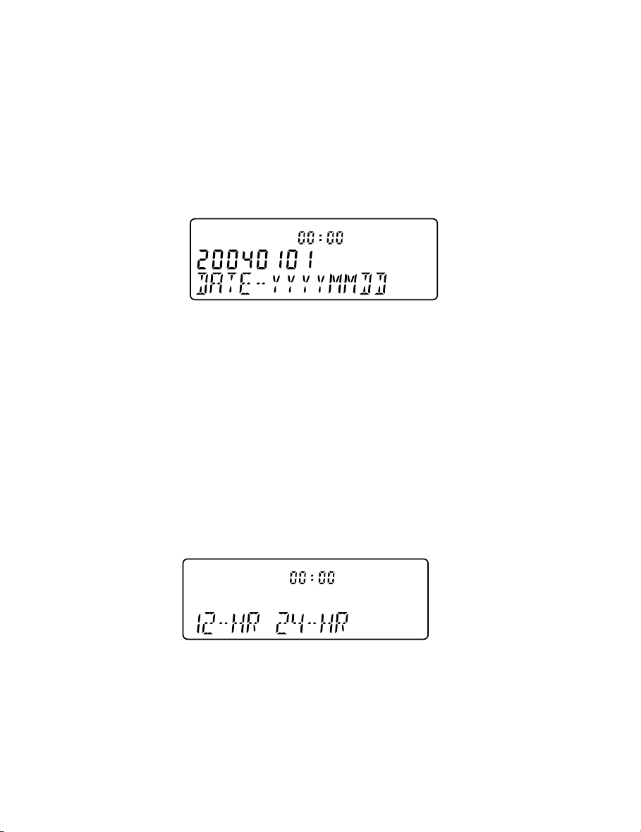
FIGURE 1A DATE SETTING
1. If the display is bla nk, lift the Ha ndset briefly to wa ke up the telephone and replace
the Handset in the cradle
2. For 10 seconds the display will show “20040101” a nd “DA TE-YYYYMMDD” when
the unit is first powered up
3. If the display is alive but not showing “20040101” and “DATE-YYYYMMDD”, press
STORE, TIMER; the display will return to the “20040101” a nd
“DATE-YYYYMMDD” mode. Proceed to ste p 4 within the next 10 seconds; repeat
step 3 if necessary to re-enter Date/Time setting mode.
4. Enter Year (4 digits), Month (2 digits) and Date (2 digits)
NEW
REPEAT
CALL#
TIMER
AM
PM
FIGURE 1B HOUR MODE SETTING
5. Hour Mode Setting - the display will now show “1-12HR 2-24HR”
6. Press 1 for 12 hour mode or 2 f or 24 hour mode display (if 24 hour mode wa s
chosen, plea se go to step 9)
9
NEW
REPEAT
CALL#
TIMER
AM
PM
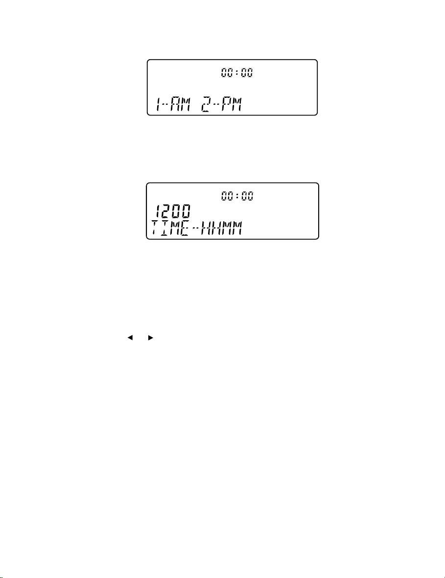
FIGURE 1C AM/PM SETTING
7. If 12-hour mode wa s selected a bove, the display will show “1-AM 2-PM”
8. Press 1 or 2 to select AM or PM time display
NEW
REPEAT
CALL#
TIMER
AM
PM
FIGURE 1D TIME SETTING
9. The display will show “TIME-HHMM” after completion of the Hour Mode Setting
10. To set the current time enter 2 digits for the hour, f ollowed by two digits f or the
minutes
1 1. The display will show “CLOCK STORED” and the date a nd time will be updated.
Note: use Cursor or to correct your numeric entries stage in the above procedure.
BASIC OPERATION
IQ750 can be used in the same way as a normal telephone; simply lift the Handset to
answer an incoming call, or lift the Handset and dial on the Keypad to commence an
outgoing call. Plea se refer to other sections f or more about Ha ndsfree, Headset, Caller ID
display and Memory operation s. The tele phone will also operate in a basic mode when
mains power has failed and if batteries have not been fitted (the telephone will
automatically power up approxi mately 1 second after lifting ha ndset). If 4 x AA alkaline
batteries (not supplied) are fitted in the absence of main s ada ptor or during main s power
failure, they can provide up to one month's support of all functions.
10
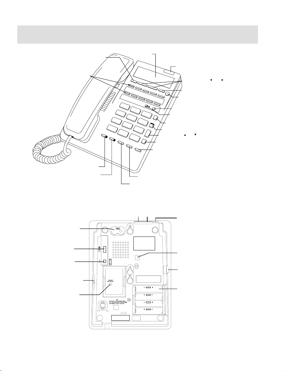
3. GENERAL CONTROLS AND INDICATORS
STORE KEY
DIRECT ACCESS
MEMORY KEYS
HANDSFREE/HEADSET KEY AND INDICATOR
MUTE KEY AND INDICATOR
RINGER PITCH
CONTROL
DISPLAY
DIRECTORY KEY
CALLER KEY WITH NEW CALL INDICATOR AND
CENTREX MESSAGE WAITING INDICATOR
SCROLL KEY ( AND )
DIAL KEY
RECALL KEY
REDIAL KEY
PAUSE KEY
FIGURE 2A: TOP VIEW
HEADSET JACK
LINE JACK
RINGER/MESSAGE WAITING INDICATOR
CURSOR KEYS ( AND )
CLEAR KEY
TIMER KEY
RESET KEY
MEMORY PROTECTION SWITCH
9V ADAPTOR JACK
RINGER VOLUME
SWITCH
HEADSET POLARITY
SWITCH
VOLUME SLIDER
HEADSET MIC
ADJUSTMENT CONTROL
MOUNTING HOLES FOR
Reversed headset
polarity
Normal headset
polarity
IQ235 WALL BRACKET
HANDSET JACK
BATTERY COMPARTMENT
(OPTIONAL BATTERIES NOT
SUPPLIED)
FIGURE 2B: BOTTOM VIEW
11

RINGER/MESSAGE WAITING INDICATOR
Located at the top right hand side of the telephone a bove the DISPLAY, the red lense
contains two different indicators; their functions are as follows:
1. Ring Indicator Flashe s when the telephone rings with a n
incoming call.
2. P ABX Message W aiting Indicator Illuminates when a message is waiting in your
P ABX voice mail system (depends on syste m
compatibility). The built-in Message Waiting
option suits any neon type (minimum 80 VDC)
message waiting system and Ericsson BP250
Message Waiting (other system types are available
a s optional extra s). To determine which P ABX type
your IQ750 ha s been prepared to suit,
check the telephone’s underside for a label indicating that specific circuitry has been
installed in your unit. If in doubt, conta ct Interquartz f or further details. To retrieve your
message, consult your voice mail system user guide.
IQ750 is also fitted with a message waiting indicator la mp which is compatible with the
voicemail features of Centrex networks (eg. Telstra Customnet) a nd residential line voicemail
systems (eg. Telstra Home Messages 101 and MessageBank). There are indicators
located in the CALLER Key and display for the se services a nd are described elsewhere
in this manual.
RINGER VOLUME SWITCH
The three available positions allow selection of OFF (no sound), LOW volume, a nd HIGH
volume of the telephone ringing sound during an incoming call (Figure 2B).
RINGER PITCH CONTROL
The pitch of the ringing sound may be altered by rotating the control to suit your preference
to achieve a distinctive sound, or one that is audible, more distinctive or more pleasant.
12

ALPHA-NUMERIC KEYPAD
In addition to normal dialling, the alphabetic chara cters are provided on the keys to enter
names in the Direct Access and Directory memories as well as any online applications
that require alphabetic keystrokes.
RESET KEY
Press to restore normal operation of the telephone in ca se of a malfunction or lock-up.
The memories will not be era sed when this key is pressed.
CRADLE SWITCH
Located in the handset cradle, this plastic lever is depressed by the Handset (when
placed in the cra dle) to cut off the line. Note: Depressing this cradle lever too briefly when
intending to terminate a call may result in a n accidental “hookflash” that will inadvertently
place the call on hold - this is known as “phantom calls” because the held call may ring
again at your extension within a few minutes (the other party will have hung up, so it will
seem as if you were called by a phantom, hence the name “phantom calls”). If you
experience this problem, when terminating your call please depress the cradle lever a
little longer before making/re ceiving your next call (i.e. phantom calls are not a system
or telephone fault).
VOLUME SLIDER
Used to adjust the hearing level of the Handset Earpiece/Handsfree Speaker/Headset.
Set to midway for normal listening level. Adjustment during a conversation will not be
detected by the other party.
RECALL KEY
For use with PABX systems to invoke special PABX facilities such as call-hold or call
trans fer which may be available in your PABX. It is sometimes referred to as the “Flash”
Key or “Facility” Key. T o learn how to use it, ple ase consult your telephone host system
manual. Recall ti ming is preset to 100mS. The Recall T iming setting affects the Recall
Key’s ability to function correctly with your system (see the Installation section regarding
this setting).
13

REDIAL KEY
Press to redial the last number last dialed, which may be up to 32 digits long. When
pressed while still on-line, the telephone will clear the call and retry the number . It ca n be
used in Handset, Ha ndsfree, a nd Headset modes. Dialing more than 32 digits during one
call will cause erasure of the entire number from the Redi al Memory.
See further details of the 5-stack Last Number Redial Memory in section 6 “Memory
Operation”.
To redial last number
1. Lift Handset, or press HANDSFREE/HEADSET
2. Press REDIAL (telephone redi als last number).
To direct redial the last number
1. Lift Handset, or press HANDSFREE/HEADSET
2. Dial a number, [unsuccessful]
3. Press REDIAL; the telephone will automatically clear and re-connect the line; the
number will be re-dialed.
PAUSE FUNCTION
The Pause command may be needed if your phone is connected to certain types of
P ABX or to any network where a momentary pause is required (e.g. between internal a nd
external dial tones).
For manual dialing:
1. Lift Handset
2. Dial a ny digits required bef ore the pause
3. Press PAUSE; the telephone will complete the dialing process once the Pause
time ha s elapsed
4. Dial the remaining digits.
The Pause function can be stored in any Direct Access or Direct Memories. See section
8 for further details.
MUTE KEY AND INDICATOR
When pressed, it cuts off transmission from the Handset, Headset and Handsfree
microphones to allow user privacy. The red light indicates when the mute condition is
active. Press MUTE again to release the mute condition.
14

HANDSFREE/HEADSET KEY AND INDICATOR
The HANDSFREE/HEADSET Key has an auto-detection function; which disables the
Handsfree mode when a He a dset is in use. When the HANDSFREE/HEADSET Key is
pressed, a red indicator will glow to show that the Handsfree or He adset mode is activated.
Press the key again to turn it off.
To use Handsfree mode
Ensure that a headset is NOT connected to the Headset Jack. Press the HANDSFREE/
HEADSET Key; the telephone will automatically operate in Ha ndsfree Mode. A red indicator
will glow to show that the Handsfree mode is activated. Press the key again to turn it off.
To use Headset mode
Connect a headset to the Headset Jack. Press the HANDSFREE/HEADSET Key; the
telephone will automatically operate in Headset Mode. A red indicator will glow to show
that the Headset mode is activated. Press the key again to turn it off.
CURSOR AND KEYS
The Cursor and Keys serve as display brightness adjustment keys in normal mode.
They serve as Edit Keys during Memory Storage.
TIMER KEY AND AUTOMATIC CALL TIMER FUNCTION
When a call is in progress, the word TIMER appears on the DISPLA Y, and the time will
count from 00:00. The call duration will be displayed for 10 seconds after the call is
terminated.
T o use the ti mer function a s a stop watch when the telephone is idle (not in use on a call)
1. Press TIMER once to view the last timer value
2. Press TIMER again to start the timer; the timer will count up from 00:00 to 59:59
and then roll over to 00:00 again
3. Press TIMER once more to stop the timer; the display will show the timer value
for 10 seconds
4. Press TIMER again to resume the clock display in less tha n 10 se conds if required.
To use the timer as a call timer, the telephone will automatically enter the Timer mode
when commencing a call. After hanging up, the timer will stop and its value will stay on
the display for 10 seconds.
15
 Loading...