

Page 1

HANDSFREE HEADSET
DISPLAY TELEPHONE
MODEL IQ560E
OPERATING INSTRUCTIONS
33
Page 2

CONTENTS
1. FEATURES ....................................................................... 4
2. GENERAL CONTROLS AND INDICA TORS .................... 6
RINGER/MESSAGE WAITING INDICATOR............................................................................................ 7
RINGER HI/LO/OFF SWITCH.................................................................................................................. 7
RINGER PITCH CONTROL ..................................................................................................................... 7
ALPHA-NUMERIC KEYPAD .................................................................................................................... 7
CRADLE SWITCH .................................................................................................................................... 7
EARPIECE VOLUME SLIDER ................................................................................................................. 8
HANDSFREE VOLUME SLIDER ............................................................................................................. 8
RECALL KEY ............................................................................................................................................8
PROGRAMMING THE CLOCK ................................................................................................................ 8
SET KEY ...................................................................................................................................................9
HOUR KEY ............................................................................................................................................... 9
MINUTE KEY ............................................................................................................................................ 9
BACK SPACE ( ) KEY ...........................................................................................................................9
CALL TIMER ............................................................................................................................................. 9
MUTE KEY AND INDICATOR ................................................................................................................... 9
BASIC OPERATION................................................................................................................................. 9
REDIAL KEY ............................................................................................................................................. 9
PAUSE FUNCTION ................................................................................................................................ 10
HEADSET KEY AND INDICATOR .......................................................................................................... 11
HANDSFREE KEY AND INDICATOR .................................................................................................... 11
DATA PORT AND SWITCH .................................................................................................................... 11
3. HANDSFREE OPERATION ............................................ 12
HANDSFREE MICROPHONE................................................................................................................ 12
USING THE HANDSFREE KEY.............................................................................................................12
HINTS FOR HANDSFREE OPERATION............................................................................................... 13
4. HEADSET OPERATION ................................................. 13
CLARIA “ALERT”FEATURE.................................................................................................................. 14
BASIC OPERATION............................................................................................................................... 14
HEADSET/HANDSET/HANDSFREE MODES....................................................................................... 14
TRAINEE/SUPERVISOR MODE ........................................................................................................... 14
TRAINING MODE ................................................................................................................................... 15
SUPERVISOR MODE ............................................................................................................................ 15
SILENT RINGING FEATURE ................................................................................................................. 15
2
Page 3

5. ADVANCED NETWORK OPERA TION ........................... 18
PAUSE FUNCTION WHEN DIALING .....................................................................................................18
HOLDING AND TRANSFERRING CALLS ............................................................................................. 18
USING THE MEMORIES........................................................................................................................ 18
6. MEMORY FEATURE OPERATION................................. 19
NON-VOLATILE MEMORIES (BATTERY FREE PERMANENT STORAGE) ....................................... 19
EEPROM MEMORY FEATURE ............................................................................................................. 19
CASCADE DIALING ............................................................................................................................... 20
MEMORY LOCK ..................................................................................................................................... 20
7. INSTALLATION............................................................... 21
UNPACKING........................................................................................................................................... 21
GENERAL SETTING-UP ........................................................................................................................ 21
LOCATION.............................................................................................................................................. 21
WALL MOUNTING..................................................................................................................................21
WALL-MOUNT BRACKET (OPTIONAL NOT INCLUDED WITH PHONE) ........................................... 23
PROGRAMMING THE CLOCK .............................................................................................................. 24
LINE CONNECTION............................................................................................................................... 24
MESSAGE WAITING LIGHT COMPATIBILITY...................................................................................... 24
HEADSET MIC ADJUST CONTROL......................................................................................................25
TO MAKE A HEADSET MIC LEVEL ADJUSTMENT : ........................................................................... 25
HEADSET POLARITY SWITCH ............................................................................................................ 25
HANDSFREE MIC ADJUST CONTROL ................................................................................................ 26
DATA PORT SWITCH.............................................................................................................................28
SHARED MODE ..................................................................................................................................... 28
SPLIT MODE .......................................................................................................................................... 28
8. GENERAL CARE AND MAINTENANCE ........................ 29
9. THUNDERSTORMS ....................................................... 30
10. WARRANTY - 6 YEARS ............................................... 31
11. SERVICE CENTRES..................................................... 31
QUICK REFERENCE GUIDE ........................................ 16,17
3
Page 4

1. FEATURES
• 6 YEAR W ARRANTY – parts and labour
• Tone dialing
• Hands free Speaker phone
• Headset function
• Large 16 digit LCD display
• User programmable 12 hour real-time clock display
• “Timer” Function provided for call duration indication
• Total 20 Non-Volatile memories (battery free permanent storage)
• 10 one touch memories
• 5 one/two touch memory with memory protection switch
• Store Key
• Fla sh, Pause, and can be stored
• Super bright LED ringer lamp allows visual ringing indication
• Built-in Message Waiting option to suit any neon (80 VDC) type message waiting
system AND Ericsson BP250 Message W aiting (other syste m type s option al)
• Recall fa cility with 100mS flash timing
• Redial and Pause function s
• User selectable ringer volume and pitch
• Mute Key and indicator - f or privacy on Handset, Handsfree and Headset mic
• Data Port and Switch to allow line sharing a nd splitting
• Built in headset socket, with adjustments to suit a wide range of headset types
• Adjustable Headset/Handset/Handsfree he aring level with slider volume control
• Headset Cable Polarity Switch to suit both common (”Normal” and ”Reversed”)
Headset plug wiring modes
4
Page 5

• Hands free and Headset Microphone sensitivity Adjustments
• Mid-call mode support (change between Hea dset, Handsfree and Handset during
a call in any order)
• Trainee/Supervisor Mode allows both a Handset user and a Headset user to be
online simultaneously without the need f or a He adset training cord or adaptor
• “Silent Ringing” feature for Headset users allows the ringing to be heard in the
Headset only (keeps call center noise levels down by eliminating the sound of
ringing during incoming calls)
• Built-in support for Claria Alert headset “Alert” indicator light function
• Compatible with direct lines, intelligent networks a nd PABXs
• Call Waiting compatible
• Telstra Customnet compatible
• Line powered, unaffected by main s power interruption
• REN (Ringer Equivalence Number) = 0.68 allows multiple parallel devices on the
same line without loa ding incoming ring
• Alpha-numeric keypad allows full access to services that require the entering of
numerals and letters
• Fully modular connection provides maximum ease of installation on desk or wall
• Hearing Aid compatible to suit “T-switch” type hearing aids
5
Page 6
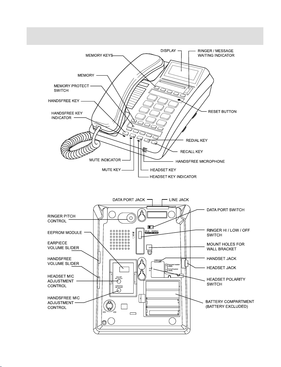
2. GENERAL CONTROLS AND INDICATORS
FIGURE 1A: TOP VIEW
FIGURE 1B: BOTTOM VIEW
6
Page 7

RINGER/MESSAGE WAITING INDICATOR
There are two different functions:
Ring Indicator: Fla she s when the telephone rings with an incoming call.
Message-Waiting Indicator: Illuminates when a message is waiting in your voicemail
system (depends on system compatibility). The built-in
Message W aiting option suits any neon (minimum 80 V DC)
type message waiting system a nd also the telephone has
Ericsson BP250 Message Waiting built-in (other system
types are optional extra s).
RINGER HI/LO/OFF SWITCH
The three available positions allow selection of OFF (no sound), LOW volume, and
HIGH volume of the telephone’s ringing sound during an incoming call (Figure 1B)
RINGER PITCH CONTROL
The pitch of ringing sound may be altered by rotating the control.
ALPHA-NUMERIC KEYPAD
The standard numeric digits are available for normal dialing. The alphabetic characters
are provided for Voice Mail and Telstra Customnet applications.
CRADLE SWITCH
Located in the handset cradle, this plastic lever is depressed by the handset (when
placed in the cradle) to cut off the line. Note: Depressing this cradle lever too briefly
when intending to terminate a call may result in an accidental “hookflash” that will
inadvertently place the call on hold - this is known as “pha ntom calls” be cause the held
call will probably ring again at your extension within a few minutes (the other party will
have hung up, so it will seem as if you were called by a phantom, hence the name
“phantom calls”). If you experience this problem, when terminating your call please
depress the cradle lever a little longer before ma king/receiving your next call (i.e. pha ntom
calls are not a system or telephone fault).
7
Page 8
EARPIECE VOLUME SLIDER
Used to adjust the hearing level of the HANDSET and HEADSET. Set to midway for
normal listening level. Adjustment during a conversation will not be detected by the
other party.
HANDSFREE VOLUME SLIDER
Used to adjust the volume of sound from the spea ker when in Handsfree mode.
RECALL KEY
For use with PABX systems to invoke special PABX facilities such as call-hold or calltrans fer which may be available in your PABX. It is sometimes referred to as the “Flash”
button or “Facility” button. To learn how to use it please consult your telephone host
system’s manual.
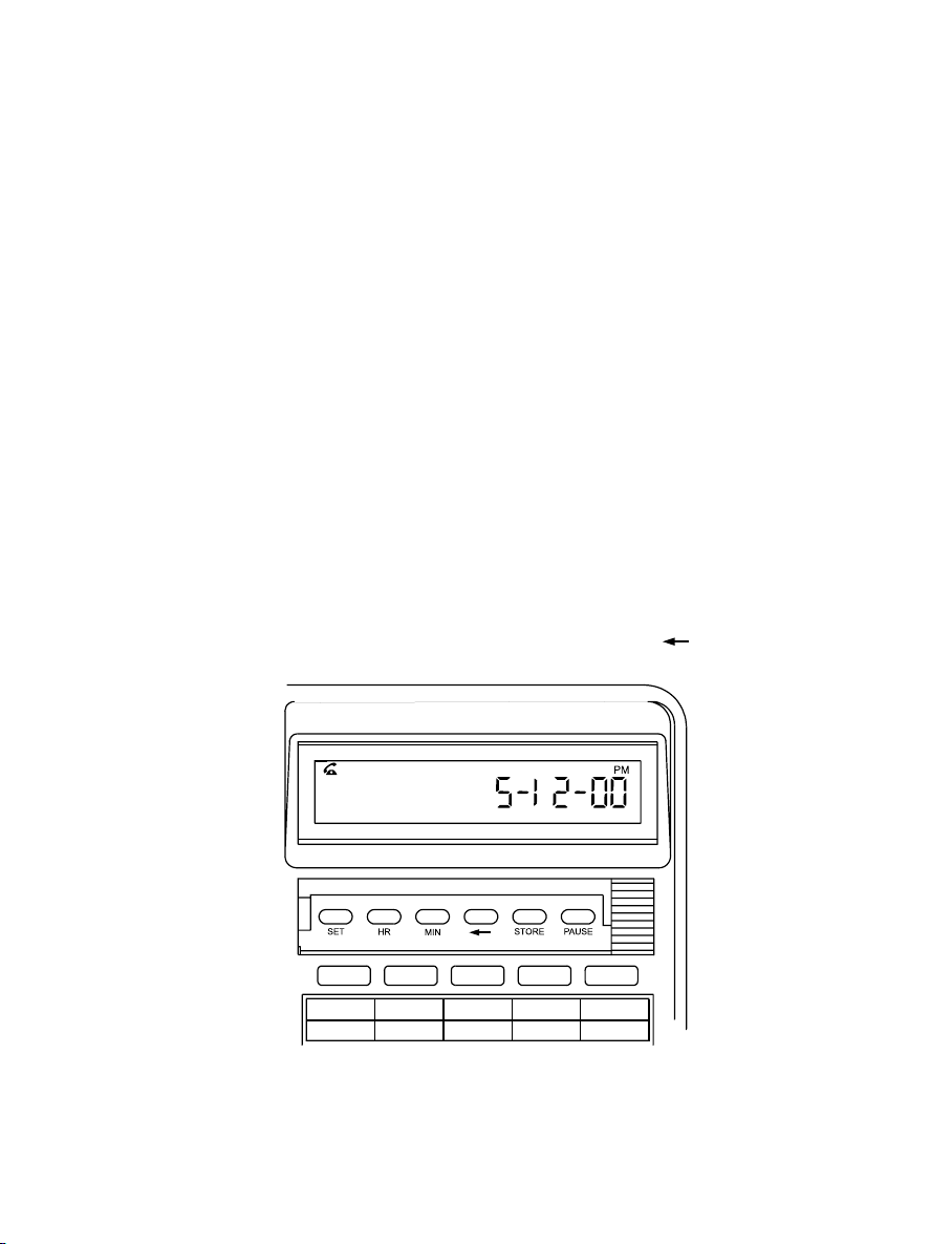
PROGRAMMING THE CLOCK -
see Figure 2 for diagram of Set, HR, Min Keys & Back Spa ce ( ) keys
Refer to programming the clock (see In stallation se ction)
FIGURE 2
8
Page 9

SET KEY
Used to set the clock.
HOUR KEY
Used to set the clock hour.
MINUTE KEY
Used to set the clock minutes.
BACK SPACE ( ) KEY
Allows editing of telephone number in store operation
CALL TIMER
When a call is in progress, the word “TIMER” on the display . When the call is termin ated,
the call duration will be automatically displayed for 6 seconds.
MUTE KEY AND INDICATOR
When pressed, it cuts off transmission from the Handset, Headset and Handsfree
microphones to allow users privacy. The red light indicates when the mute condition is
active. Press MUTE again to rele ase the mute condition.
BASIC OPERATION
IQ560E can be used in the same way as a normal telephone; simply lift the HANDSET
to answer a n incoming call, or lift the HANDSET and dial on the KEYPAD to commence
an outgoing call. Please refer to other sections for detailed operation instructions.
REDIAL KEY
Press to redial the last number previously dialed, which may be up to 32 digits long.
When pressed while still on-line, the telephone will clear that call and retry the number.
It can be used in ha ndset, handsfree, and hea dset mode s. Dialing more than 32 digits
during one call will cause era sure of the entire number from the REDIAL memory.
9
Page 10

EXAMPLE: TO REDIAL LAST NUMBER
1. Lift HANDSET, or press HANDSFREE or HEADSET,
2. Press REDIAL (telephone redials last number).
EXAMPLE: DIRECT REDIAL OF LAST NUMBER
1. Lift HANDSET, or press HANDSFREE or HEADSET,
2. Dial a number, but find it engaged,
3. Press REDIAL; the telephone will automatically clear and re-conne ct the
line. The number will then be re-dialled.
PAUSE FUNCTION
The Pause command may be needed if your phone is connected to certain types of
PABX or to any network where a two second pause is required (e.g. between internal
and external dial tones).
For manual dialing:
1. Lift HANDSET,
2. Di al any digits required before the pause,
3. Press P AUSE (telephone waits for 2 seconds before proceeding),
4. Dial the remaining digits.
For memory usage (storage procedure) to cause the telephone to pause for 2
seconds in a sequence:
1. Lift HANDSET, or press HANDSFREE or HEADSET,
2. Press STORE,
3. Dial digits required before the pause,
4. Press PAUSE,
5. Select and press desired MEMORY KEY,
6. Replace HANDSET or press HANDSFREE or HEADSET.
10
Page 11

When dialed, this stored number will PAUSE at the appropriate place in the dialing
sequence.
HEADSET KEY AND INDICATOR
When the HEADSET KEY is pressed a red indicator will glow to show that the HEADSET
mode is activated.
HANDSFREE KEY AND INDICATOR
When the HANDSFREE KEY is pressed a red indicator will glow to show that the
HANDSFREE mode is activated.
DATA PORT AND SWITCH
The data port provides access to the telephone line for computers (with a modem),
answering ma chines a nd cordless phones. The Data Port Switch (see Fig.1B) determines
whether the Data Port shares the line with the tele phone (position SHARED) or has its
own line (position SPLIT).
11
Page 12

3. HANDSFREE OPERATION
HANDSFREE MICROPHONE
Located at the front of the phone (Figure 1A), its function is to reproduce your voice a s
you speak to the other party while your telephone is in HANDSFREE mode. Positioning
of the telephone, and therefore the MICROPHONE, is important to ensure the best
reproduction of your voice.
USING THE HANDSFREE KEY
To commence a HANDSFREE call press the HANDSFREE KEY ; the telephone will
activate the line, the SPEAKER, and the HANDSFREE MICROPHONE, and the
INDICATOR will switch on to provide confirmation. Dialing and speech can then
commence. Pressing the key again will terminate the call.
Incoming calls using HANDSFREE:
1. Telephone rings
2. Press HANDSFREE
3. Commence your HANDSFREE conversation.
Changing from HANDSFREE to HANDSET during a call:
Lift the HANDSET and resume your conversation; the HANDSFREE function will switch
off automatically.
Changing from HANDSET to HANDSFREE during a call:
1. Press HANDSFREE
2. Replace HANDSET
3. Resume your conversation using the hands free function.
12
Page 13

Outgoing calls using HANDSFREE (manual or me mory dialing):
1. Press HANDSFREE
2. Dial required number on ALPHA-NUMERIC KEYPAD or press desired MEMORY
Key
3. Speak as required.
HINTS FOR HANDSFREE OPERATION
As a courtesy, tell the other party that you are using the handsfree function. He/She
may or may not want people other tha n you to hear the conversation. A quiet environment
ensures best ha ndsfree performance. When HANDSFREE is used in a noisy room or
near a noise generating device ( for example, a TV set ) all or part of the message may
be interrupted and cannot be heard. To eliminate this problem try to lower the noise
level in the room.
During the hands free conversation, your tele phone will give priority to the person who
speaks louder when both people are talking simultaneously. Speak ONLY after the
other person pauses or stops.
If the other person complains about poor transmission, talk directly at your telephone
and from a closer distance as necessary, or lower the speaker volume control.
If the operation of the handsfree feature is not correct, refer to the FAILURE TO
OPERA TE se ction.
13
Page 14

4. HEADSET OPERATION
The IQ560E can be configured to suit many different headsets - please consult the
INST ALLATION section for details to get the best performance from your headset.
CLARIA “ALERT” FEATURE
The IQ560E is designed to support the “Alert” feature available on the Claria he adset.
When pressing the HEADSET key on the telephone, the “Alert” indicator on the Claria
headset will illuminate, signifying that the user is on a call. This feature can be used
effectively in call center a pplication s so that the user’s colleagues will be aware that the
user has a call in progre ss.
BASIC OPERATION
To make or receive an outgoing call using the headset:
• Press the HEADSET Key. Dial tone will be heard in the HEADSET
• If you are making an outgoing call, dial the required number on the keypad
• Lifting the handset during hea dset mode will revert to handset mode operation
• To revert back to headset mode operation during handset mode, pre ss the HEADSET
Key
• To hang up, press the HEADSET key or replace the handset.
HEADSET/HANDSET/HANDSFREE MODES
A call can be moved from one mode to any other by pressing the appropriate key
(Headset or Ha ndsfree) or by lifting the Handset.
TRAINEE/SUPERVISOR MODE
Allows for the HANDSET and a HEADSET to be used in tandem. This will enable a
supervisor to monitor a trainee’s progress during a call, or ‘take over’ a call. The f ollowing
procedures a ssume that the trainee is wearing the HEADSET and a call is in progress.
14
Page 15

TRAINING MODE
Allows a supervisor to monitor a trainee during a call.
1. During a trainee’s call the supervisor may lift the HANDSET (HEADSET indicator will
turn off)
2. Quickly press the HEADSET key and the HEADSET indicator will illuminate again
3. The trainee may continue the conversation with the supervisor only listening to its
progress.
SUPERVISOR MODE
Allows a supervisor to “take over” a call between a trainee and another party.
1. During a call, the supervisor may lift the HANDSET to continue a normal conversation
with the other party while the trainee listens to its progress through the HEADSET
2. To return the call to the trainee, press the HEADSET key and repla ce the HANDSET
in the cradle.
SILENT RINGING FEATURE
Designed for Call Centers or a ny application where call-related noise is to be kept to a
minimum, this feature allows incoming calls to ring silently; the operator is aware of the
incoming call, but the telephone does not add to the room noise even when ringing.
To use the telephone in Silent Ringing mode:
1. Set the RINGER VOLUME SWITCH to the OFF position (signified by the square
symbol without a bell symbol inside it
2. Put your headset on a nd wait for the next incoming call
3. When a call arrives, the RINGER / MESSAGE WAITING INDICATOR will flash and
the operator will hear the ringing tone at a low level in the headset
4. Press the HEADSET key to answer the call.
15
Page 16
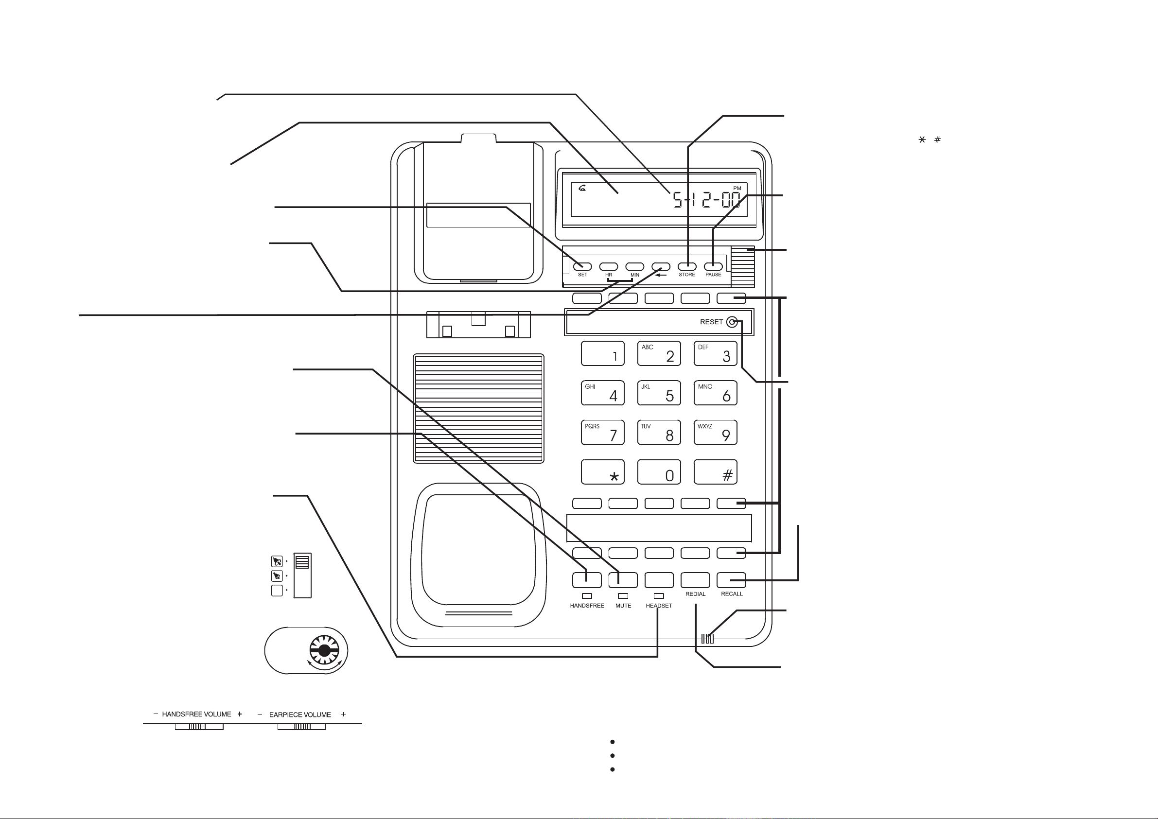
CALL TIMER
When a call is in progress, the word “TIMER” appears
on the display. When the call is terminated, the call
duration will be automatically displayed for 6 seconds.
16 digit LCD Display
Displays Clock, Call Timer and number dialed.
SET Key
Use to set the clock in 12-hour mode with PM indication
MODEL IQ560E FEATURES
See overleaf for more details
STORE Button
Use to store memories. Any memory can store 24 digits with any combination of
numeric entries plus PAUSE, , and Recall (Flash) commands.
PAUSE Key
Pause may be required if your phone is connected to any network where a 2
second pause is needed during dialling. Lift the handset, dial any digits
required before the pause, press Pause button, and dial remaining digits.
Hour (HR) and Minute (MIN) Keys
Press SET key then HR and MIN keys to set the clock.
Press SET key again to complete the clock setting.
BACKSPACE Key
Deletes the last digit of a telephone number during memory
storage.
MUTE Button and Indicator
Press to cut off transmission from the Handset, Headset and
Handsfree microphone to allow user privacy. The red light
indicates when the mute condition is active. Press MUTE
again to release the mute condition.
HANDSFREE button and indicator
Press HANDSFREE to conduct a handsfree conversation. A
red indicator will glow. Press HANDSFREE again to turn it off.
HEADSET button and indicator
Press the Headset button to conduct a call in HEADSET
mode. The indicator glows when the HEADSET mode is
activated.
Ringer/Message Waiting Indicator
Flashes when the telephone rings with an incoming call.
Built in message waiting suits both High Voltage (80 VDC) and Polarity Reversal
types. (Other system types are optional).
Memory Keys
Upper row of 5 memory keys has both one and two touch memories and can be
protected to prevent over-writing - network facility codes may be programmed
here for ease of use. Lower rows of 10 memory keys have one touch memories.
To store, lift HANDSET, press STORE, enter number, press Memory key and
hang up. See overleaf for explanation of one-touch and two-touch memories.
Reset button
Press this button to reset the telephone to normal if the telephone appears to
be malfunctioning.
The memories will not be erased when the button is pressed.
RECALL Button
For use with the host telephone system to invoke special network facilities such
as call hold or call-transfer which may be available in your PABX or network.
See your telephone system user guide to learn how to use it. May be called
"Flash" or "Facility" key.
Flash timing is preset to 100mS.
Ringer Volume switch (Hi/Low/Off)
Selection of OFF (no sound), LOW volume, and
HIGH volume of the telephone's ringing sound.
When the switch is set to OFF, the ringing sound can
still be heard via the headset if connected to
the headset port (headset optional extra).
Located on the underside.
Ringer Pitch Control
Rotate the control to adjust the ringer pitch.
Located on the telephone's base.
Handsfree volume slider
Adjusts the volume of sound from the speaker.
Located on the side of the telephone.
Handsfree microphone
RINGER
PITCH
Reproduces your voice as you speak to the other party in HANDSFREE
mode. Keep clear of obstructions to enable clear reproduction of your voice.
REDIAL Key
Press the button to redial the last number (max 32 digits).
Figure 1
To access a more detailed, downloadable user manual:
Earpiece volume slider
Adjusts the hearing level of the HANDSET / HEADSET.
Set to midway for normal listening level.
Located on the side of the telephone.
16 17
please visit our website at www.interquartz.com.au or www.telephones.com.au or
call 1800 6 IQTEL (1800 647 835),
send an email to [email protected]
Page 17

5. ADV ANCED NETWORK OPERATION
Where this telephone is used on an intelligent network such as Easycall, Customnet,
Centel, a P ABX or other network the following information may be useful.
PAUSE FUNCTION WHEN DIALING
Depending on your telephone system, this may or may not be required. If in doubt,
check with your system supplier or Interquartz dealer , a s failure to observe your system’s
requirements may lead to difficulty in making outgoing external calls. If you have
determined that a pause is required by your host system, please refer to the PAUSE
Function section to ensure correct usage of the PAUSE button.
HOLDING AND TRANSFERRING CALLS
The method used for these functions is dependent on your system type, so you will
need to check your system’s Extension User Guide. The RECALL KEY is typically used
to trans fer calls. It is affe cted by the setting of the a djustment switches de scribed in the
INST ALLATION section of this manual. They must be corre ctly set to suit your syste m
for correct operation.
USING THE MEMORIES
Any combination of numbers, and and can be stored. You may find it useful to
store some of your favourite network facility commands in the telephone for fast,
convenient access to those facilities (e.g. diversion, call forward, call ba ck etc). Consult
your system User Guide for the codes that you need to store.
18
Page 18

6. MEMORY FEATURE OPERATION
The telephone ha s 20 memories in total, distributed over 15 keys, to provide easy dialing
of often-used numbers. The upper row of 5 memory keys ha s both one and two touch
memories, and the lower rows of 10 memory keys ea ch have a one touch me mory (see
Figure 5).
NON-VOLATILE MEMORIES (BATTERY FREE PERMANENT STORAGE)
Each memory can store 24 digits with any combination of numeric entries, PAUSE , ,
and Recall commands. Batteries are not required to back up the memories of the
IQ560E. They will be permanently retained until overwritten by a new storage operation
for the user.
EEPROM MEMORY FEATURE
The IQ560E can be pre-set with user-selected codes for the 10 Memories accessible
from the five Memory buttons located near the display (five ONE T OUCH a nd five TWO
TOUCH memories). Any often-used or complex network numbers or network facility
codes can be installed at the point of sale to eliminate the need to consult confusing
system user guides. Custom-progra mming can enha nce a nd simplify phone a nd network
operation, thereby reducing the demands on staff training. The pre-programming can
alter at a later stage to allow changes to be made - see the MEMORY LOCK section
below.
Storing a number:
1. Lift HANDSET or press HANDSFREE or HEADSET,
2. Press STORE,
3. Enter the telephone number,
4. Press the desired MEMORY key either once for a “ONE TOUCH” memory (any
memory button), or twice for a “TWO TOUCH” memory (only the top row near the
display).
5. Replace HANDSET or press HANDSFREE or HEADSET.
19
Page 19
Dialing a number:
1. Lift HANDSET or press HANDSFREE or HEADSET,
2. Press desired memory key.
CASCADE DIALING
The contents of any memory can be “cascaded” or added together with additional
manual dialing or other memories.
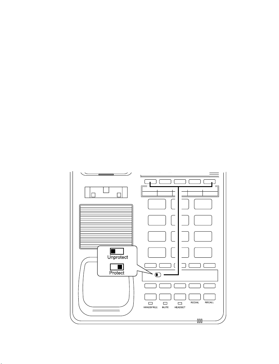
MEMORY LOCK
The upper row of memory keys can be progra mmed and, if required, they can be locked
to prevent them being overwritten. The memory protect switch is located underneath
the lower memory number card (see Figure 3), and prote cts the upper row of five memory
button only.
FIGURE 3 - MEMORY PROTECT SWITCH
20
Page 20

7. INSTALLA TION
UNPACKING
The carton contains the following:
• Telephone body and handpiece.
• Coiled handset cord and line cord.
• User Manual or Quick Start-up Gudie.
GENERAL SETTING-UP
1. Fit the COILED COR D to the appropriate sockets in the HANDSET and the telephone
base – please do not connect it to the HEADSET socket located on the side.
2. Fit the LINE CORD to the rear socket and to your telephone network outlet.
3. Set the Ringer Volume and the Ringer Pitch controls.
4. See following sections to complete the installation.
LOCATION
The telephone should be placed on a desk, table or shelf where it is not likely to be
pushed off. If the unit is to be wall-mounted, it should be seated securely on the WALL
MOUNTING BRACKET (please order separately). Avoid excessive heat, damp, dust,
direct sunlight, vibration, and other appliances or devices which may transmit or emit
electrical or electromagnetic radio frequency noise or signals (e.g. computers, welders,
pagers).
WALL MOUNTING
1. To enable the HANDSET to be supported in the cradle, follow the procedure
shown in (Figure 4A) to reverse the HANDSET RETAINER
2. Fit the WALL MOUNT BRACKET (optional, not supplied) to the underside of the
telephone and mount on the MODULAR WALL JACK (see Figure 4B).
3. During ite m 2 above, ensure that the link cord is connected as shown to the
telephone and wall jack.
21
Page 21
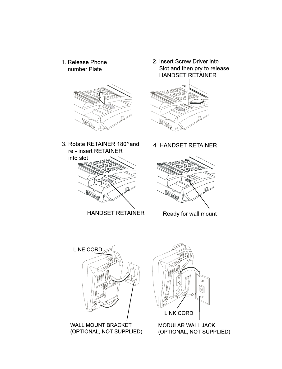
NOTE: The WALL MOUNT BRACKET, MODULAR WALL JACK and LINK CORD
illustrated in Figure 4B are available from your authorized Interquartz dealer and can be
ordered a s all Mount Kit No.3
FIGURE 4A : WALL MOUNTING
FIGURE 4B : WALL MOUNT BRACKET
22
Page 22
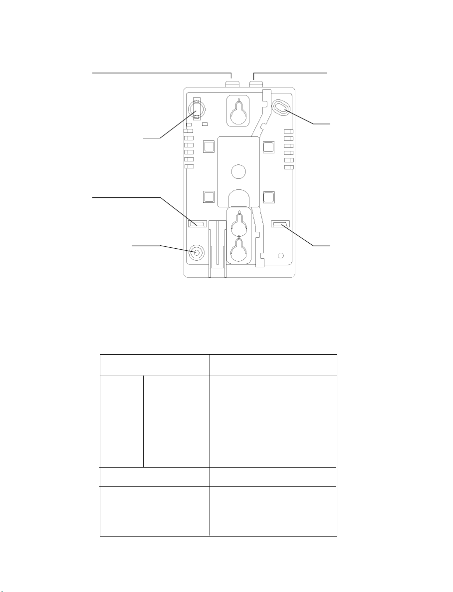
WALL-MOUNT BRACKET (OPTIONAL NOT INCLUDED WITH PHONE)
LUG "B"
PIVOT FOR SWING-OUT
PLATE USED FOR
MODEL IQTEL 25
LUG "C"
MOUNTING HOLE "F"
LUG "A"
MOUNTING
HOLE "E"
LUG "D"
Please note:
1. This wall bracket may be secured onto the wall by using mounting holes “E” and “F”
2. Lugs to break off before wall mounting the phone.
TELEPHONE MODELS
IQ 90
IQ 150
IQ 250
IQ 260
IQ 360
IQ 350
IQ 450
IQ 550
IQ 560E
IQ E2
IQ E3
IQTEL 80
IQTEL 300
IQTEL 500
IQTEL E1
IQTEL E2
IQTEL E3
IQTEL ET
STUDIO 20
GEMINI SERIES
IQTEL 25
IQ 300
9853 XT
9835 MKII
9836
9837
BREAK OFF LUGS
"B" and "D"
"A" and "C"
"A" ONLY
FIGURE 5
23
Page 23

PROGRAMMING THE CLOCK
Example : 5:12 pm
1. Lift HANDSET or press ”HANDSFREE”
2. Press SET
3. Press HR repeatedly until “05” and “PM” appears on the display
4. Press MIN repe atedly until “05-12” appears on the display
5. Press SET. The real time clock will be stored.
NOTE : ”HR” and ”MIN” count forward as long as the key is pressed, ”P” represents
PM and no “P” means AM.
LINE CONNECTION
This telephone is supplied with a RJ45 Plug as the wall plug, with the centre pair
being reserved for speech and signaling. Other types of plugs and cords are availa ble
on request.
TECHNICAL ADJUSTMENTS - FOR CORRECT OPERATION
MESSAGE WAITING LIGHT COMPATIBILITY
The Message Waiting Light ca n be optionally configured at ti me of order to be compatible
with most host telephone systems on the Australi a n market. The sta ndard factory fitted
message waiting light is a neon style circuit suitable for minimum 80V DC signaling and
is compatible with NEC, FUJITSU, ALCATEL, later HYBREX and NORTEL PABX
systems.
If this telephone is configured to “message waiting” mode please note that it is only for
P ABX systems (contact your vendor for clarification). If it is connected so, it may not be
connected to any other telephone system or network without the authority of the Australia n
T elecommunication s Authority .
24
Page 24

HEADSET MIC ADJUST CONTROL
This control allows many dif ferent headsets on the Australi an market to function corre ctly
with the IQ560E telephone by adjusting the HEADSET’S Microphone sen sitivity . The
control is located on the underside of the telephone (see Figure 6). The adjustment can
be made by a small screwdriver or similar implement that will fit into the control slot.
Plea se see Table 1 as a guide to the correct settings for some popular headsets.
TO MAKE A HEADSET MIC LEVEL ADJUSTMENT :
With the headset connected as per the instructions in this manual:
1. Put the headset on and lift the HANDSET to your other ear and make an out-going
call
2. Pressing the HEADSET key, swap between HANDSET and HEADSET mode (The
indicator will illuminate when the HEADSET is in use) a few times while spe aking to
the other party
3. With the other party’s help decide if your voice level is the same when using the
HANDSET and HEADSET.
4. If you sound too loud on the headset, adjust the microphone sensitivity (turn anticlockwise) so that your voice level when using the HEADSET matches that of the
HANDSET. Clockwise rotation increases the HEADSET mic output level. Please
see Table 1 as a guide to the correct settings for some popular headsets.
HEADSET POLARITY SWITCH
Located on the underside of the telephone (see Figure 6), this switch provides
compatibility with the two commonly-used headset wiring sta ndards.
Position ‘V’ suits Plantronics Vista Cords and other Headsets wired in the same
configuration (also known as “reversed” wiring mode).
Position ‘P’ suits Plantronics P cords a nd other Headsets wired in the same configuration
(also known as “normal” wiring mode).
Plea se see (Table 1) as a guide to the correct settings for most popular hea dsets.
25
Page 25
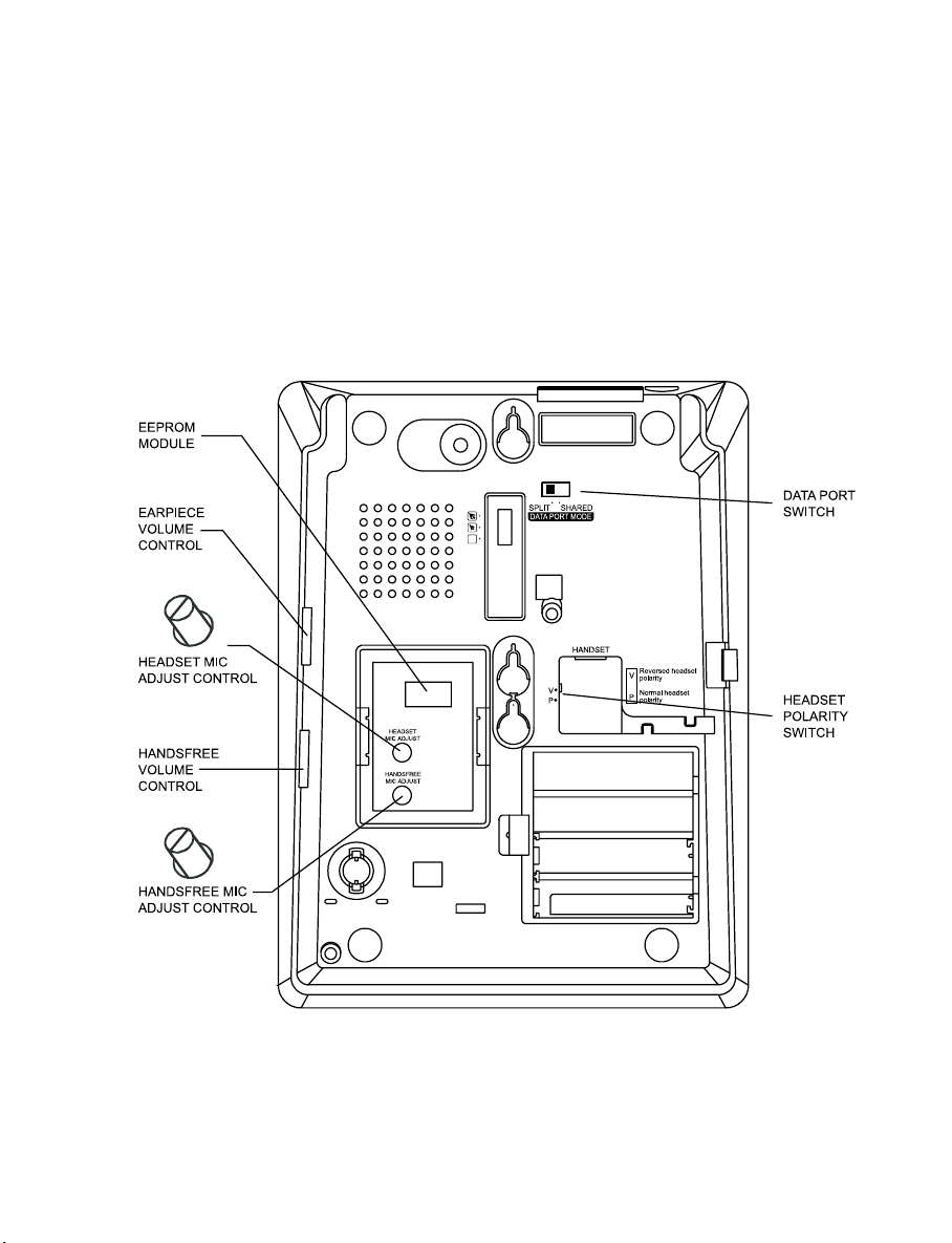
HANDSFREE MIC ADJUST CONTROL
Located on the underside of the telephone (see Figure 6), this control allows the user to
re-adjust their voice level as heard by the person they are speaking to. Using a small
screwdriver or similar implement that will fit into the control slot, turn the control clockwise
to increa se your voice level and anti-clockwise to decrease your voice level. Adjust the
control to achieve opti mum handsfree performa nce.
FIGURE 6
26
Page 26
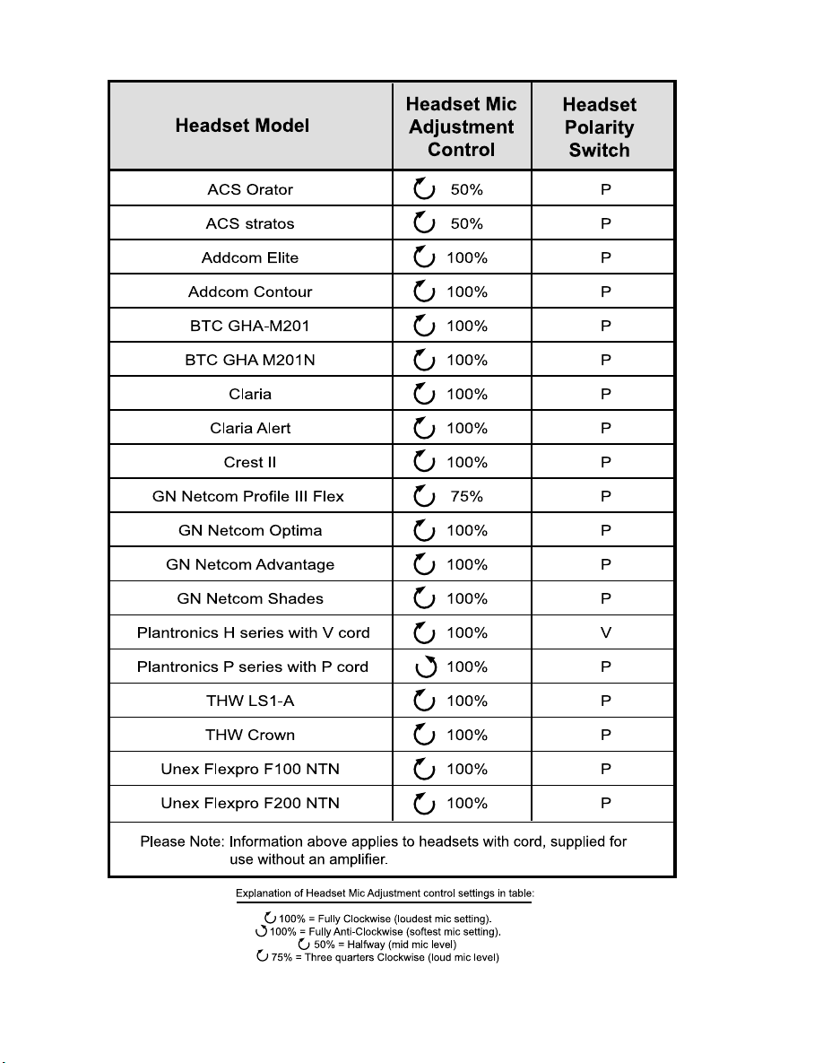
TABLE 1
27
Page 27
DATA PORT SWITCH
The data port switch (SHARED or SPLIT) determines whether the data port shares the
line with the telephone (position “shared”) or ha s its own line (position “split)
SHARED MODE
This mode uses one analog telephone line and provides the user with a ccess to a Data
Port, but in this mode the telephone’s voice ca pa bility is disabled while the Data Port is
in use. The line cord as supplied is terminated with RJ45 at the wall end. For Shared
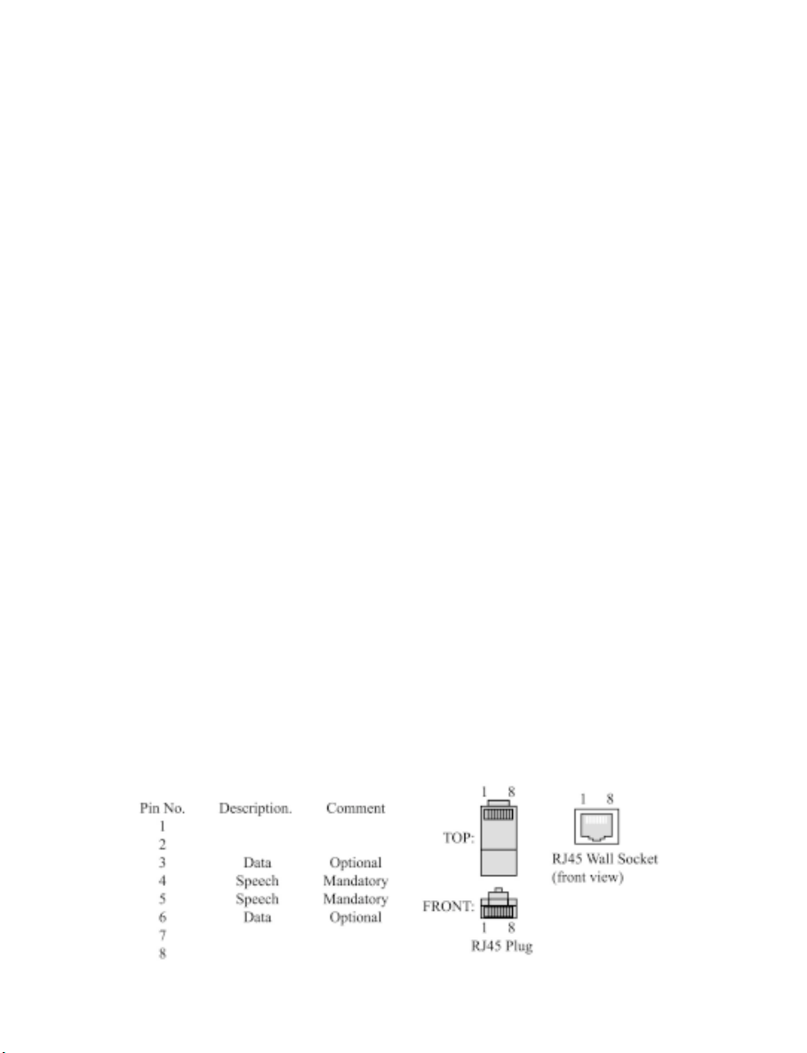
mode the telephone line should be terminated on pins 4 and 5 of the matching RJ45
compatible wall socket. Different plug or cord types can be provided to suit your wall
socket – plea se contact Interquartz or your dealer. The telephone will be factory set in
SPLIT mode.
SPLIT MODE
To enable the user to simultaneously access both the Data Port and the telephone (i.e.
“SPLIT” mode) a second analog line must be allocated to the Data Port, and the Data
Port Mode Switch must be set to Split mode. The line cord as supplied is terminated
with RJ45 at the wall end, with the voice pair in the middle (pins 4 and 5) and the
dedicated data line pair (for “Split” mode) on pins 3 a nd 6. For Split mode the telephone
line pair should be terminated on pins 4 and 5 of the matching RJ45 compatible wall
socket. The new dedicated an alog DATA line pair must be terminated on pins 3 and 6
of the RJ45 compatible wall socket where the voice pair is also located. Different plug
or cord types can be provided to suit your wall socket – please contact Interquartz or
your dealer. The telephone will be factory set in SPLIT mode. The Data Port Mode
Switch is found on the underside of the telephone (See Figure 6).
FIGURE 7 PIN ASSIGNEMNT OF RJ45 LINE CORD PLUG
28
Page 28

8. GENERAL CARE AND MAINTENANCE
This telephone is a precision electronic instrument. While in use a nd storage, care should
be taken to avoid rough ha ndling, extreme te mperature, and damp or dirty environ ments.
CLEANING
NEVER use aerosol sprays or other chemical agents or substa nces that leave a residue
(furniture polish for example).
Use a mild detergent and a damp, clean cloth when cleaning. Do not allow moisture to
enter the telephone’s interior - da mage may result!
FAILURE TO OPERA TE AND SERVICE DIFFICUL TIES
If telephone service problems occur at any ti me, it is re commended that the installation
procedure described in this manual be re-che cked.
If a fault occurs, try to determine if the fault is with the telephone, or with the network or
system to which the telephone is connected:
Disconnect the “suspect” telephone, a nd test the line with a substitute telephone. If the
telephone service then operates satisfactorily , the fault is in the “suspe ct” tele phone.
Test the “suspect” telephone on a known good line. If the fault still occurs, the fault is in
the “suspect” telephone.
Consult your Interquartz dealer for further advice if necessary.
29
Page 29

9. THUNDERSTORMS
The telephone, in common with household electrical appliances, can be a source of
electric and acoustic shock during thunderstorms. The possibility of a telephone user
experiencing a shock is minimal. Nevertheless, customers should be aware of some
simple precautions to follow during thunderstorms:
Use your telephone only for calls of the utmost urgency. Keep these calls brief.
Whilst using your telephone keep clear of electrical appliances and metal fixtures such
as : stove s, air conditioners, refrigerators, window frames and sinks.
30
Page 30

10. WARRANTY - 6 YEARS
Interquartz (A’Asia) Pty Ltd warrants the origin al purcha ser against failure, under normal
usage and in the environment and network for which it was designed, resulting from
defective material a nd workmanship at time of manufacture for a period of SIX YEARS
from the date of purchase. Proof of purchase and date of purchase are required for
determining validity of this warranty. This warranty does not cover defects or damage
due to normal wear and tear, negligence, accidents, exposure to radiation, misuse,
obsolescence, incompatibility , i mproper mainten ance, lightning strikes or unauthorized
repairs or modifications and excludes freight or postage costs to/from your local
authorized service centre unless otherwise arranged. Con sequential loss not included.
Notification of any defect must be made within the warranty period before a warranty
repair can be effe cted. This guara ntee is in addition to all other W arra nties or Guarantee s
expressed or implied by the Trade Practice s Act or other Commonwealth or State laws
and all other obligations and liabilities on the part of Interquartz (A’Asi a) Pty. Ltd.
11. SERVICE CENTRES
Please call 1800 6 IQTEL (1800 647 835) from anywhere in Australia to arrange service
or repair of your telephone.
31
Page 31

3C585001-03
International Quartz Limited
Manufactured by
A Subsidiary of Chiaphua Industries Ltd.
©Copyright INTERNATIONAL QUARTZ LTD. 2007
32
 Loading...