

21
OPERATING INSTRUCTIONS
Headset Speakerphone

1
Contents
1. Important Notes...................................................................... 2
Intended use...............................................................................................2
Telephone facilities ..................................................................................... 2
REN number...............................................................................................3
Emergency calls .........................................................................................4
2. Installation .............................................................................. 5
Connection .................................................................................................5
Wall mounting.............................................................................................5
3. T elephone Features................................................................ 7
4. Operation ..............................................................................11
5. PABX & System Usage ........................................................ 14
6. Maintenance and Problem Solving.....................................16
7. Warranty and Service........................................................... 17
Figure 1 Wall Mounting.............................................................................5
Figure 2 Handset Retainer for Wall Mount................................................6
Figure 3 General Appearance ..................................................................7
Figure 4 Bottom View ...............................................................................9
Figure 5 Recall Switch............................................................................14

2
1. Important Notes
Intended use
This apparatus is intended for use on 2 wire analogue PSTN and PABX circuits
within Europe.
Declaration of Conformity
Interquartz (UK) Limited declares under its sole responsibility that this
product
Model: Enterprise Headset Speakerphone
Is in conformity with the following relevant harmonized standards
Health & Safety 73/23/EEC
Electromagnetic Compatibility EN55022 :1998 & EN55024 : 1998
Telecom TBR21 : 1998 & TBR38 : 1998
Following the provisions of Council Directive on radio equipment and telecommunications terminal equipment.
January 2001
Telephone facilities
This telephone has been designed for the use of the following facilities :
manual or handsfree dialling
headset port
recall (earth or timed break switchable)
MF signalling
ringer indicator

3
ringer volume control
ringer pitch adjust
redial / pause
mute function with LED indicator
line powered
triple standard message waiting
(high voltage, reverse polarity + voltage drop)
20 memories accessed via 10 memory button (10 one touch and 10 two
touch memories)
EEprom lockable memories (EEprom memory selector underneath memory
card)
inductive loop hearing aid compatible
desk or wall mountable (no bracket required)
REN number
The REN number of this telephone is 1.
If you wish to connect any other equipment to the line, simply add the REN
numbers of each piece together and ensure that the total does not exceed 4.
If too many phones are connected to the line, the circuit may be overloaded
and your telephone may not ring.
Not all telephones have the same REN.
If a British Telecom phone is supplied unmarked, you can assume that it has
a REN of 1

4
Emergency calls
Calls can be made on this telephone to contact the emergency services. An
access code may also be required, if the phone is connected to a PABX. The
European code for emergency services is 112, however, you can still use 999
in the UK.
5
2. Installation
This telephone is designed to plug straight into a modular style socket. If you
do not have one of these sockets, they can be obtained from your Network
Supplier.
Connection
Insert the line cord into the socket. Set the ringer volume and pitch control as
desired.
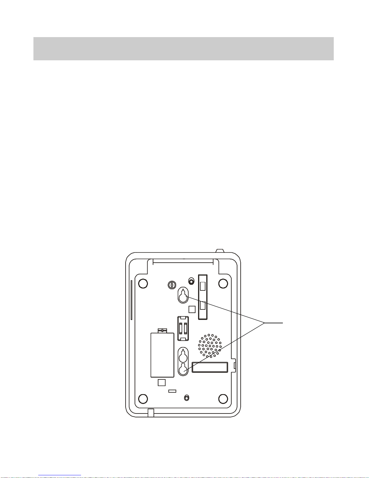
Wall mounting
Using the template supplied, position the telephone where you want to wall
mount. Drill two holes and fix round headed screws, leaving them slightly proud
of the surface. Position the telephone over the screws and slide downwards
into place.
FOR WALL MOUNT
Figure 1
Wall Mounting

6
To enable the handset to be supported in the cradle when the phone is mounted
on the wall, follow the procedure shown in Figure 2 to reserve the HANDSET
RETAINER.
2. Push the HANDSET RETAINER
out of the slot
1.Use your thumb to press the
HANDSET RETAINER
4. Insert the HANDSET RETAINER
back into it's slot
3. Turn the HANDSET
RETAINER 180.
Figure 2
Handset Retainer for Wall Mounting
 Loading...