

Page 1

Internet BroadBand Router
【4 Port / 7 Port / 8 Port】
User Guide
Doc. No.: 032102-01
Page 2

Table of Content
INTRODUCTION............................................................................................................................................................................... 1
APPLICATIONS: .................................................................................................................................................................................. 1
HARDWARE INSTALLATION....................................................................................................................................................... 2
HARDWARE REQUIREMENTS:............................................................................................................................................................. 2
PARTS NAMES AND FUNCTIONS ......................................................................................................................................................... 2
HARDWARE CONNECTIONS ................................................................................................................................................................ 2
Install the network card ................................................................................................................................................................ 3
Connect the Internet BroadBand Router....................................................................................................................................... 3
Check the installation.................................................................................................................................................................... 3
Connect the Internet BroadBand Router....................................................................................................................................... 4
CONFIGURATION............................................................................................................................................................................ 5
NETWORK TCP/IP SETTINGS:............................................................................................................................................................ 5
Windows 95/98/ME ....................................................................................................................................................................... 5
Windows 2000............................................................................................................................................................................... 7
Windows NT4.0 ............................................................................................................................................................................. 8
INTERNET BROADBAND ROUTER CONFIGURATION ............................................................................................................................ 8
ADSL DIALUP CONFIGURATION (ADSL PPPOE) ............................................................................................................................. 8
CABLE MODEM CONFIGURATION ...................................................................................................................................................... 9
ADSL LEASED LINE CONFIGURATION .............................................................................................................................................. 9
SETTING UP (WEB CONFIGURATION)............................................................................................................................................... 10
Quick Setup ................................................................................................................................................................................. 11
WAN Interface........................................................................................................................................................................ 11
LAN Interface ......................................................................................................................................................................... 12
Advanced Setup........................................................................................................................................................................... 13
PPPoE Setup ........................................................................................................................................................................... 13
Administration ........................................................................................................................................................................ 13
DHCP Server........................................................................................................................................................................... 14
Static Route............................................................................................................................................................................. 15
Outgoing Policy ...................................................................................................................................................................... 15
Incoming Policy ...................................................................................................................................................................... 17
Virtual Server.......................................................................................................................................................................... 18
Mapped IP............................................................................................................................................................................... 19
Special Application ................................................................................................................................................................. 20
DNS Proxy.............................................................................................................................................................................. 21
Hacker Alert............................................................................................................................................................................ 22
Software Update...................................................................................................................................................................... 23
Monitor ....................................................................................................................................................................................... 23
Connection Log....................................................................................................................................................................... 23
Traffic Log .............................................................................................................................................................................. 24
Per User Statistics ................................................................................................................................................................... 24
Statistics .................................................................................................................................................................................. 25
Status....................................................................................................................................................................................... 25
FAQ .................................................................................................................................................................................................... 27
Page 3
INTRODUCTION
With the explosive growth of the Internet, accessing information and services at any time, day or night has become a standard
requirement for most people. The era of the standalone PC is waning. Networking technology is moving out of the exclusive
domain of corporations and into homes with at least two computers. Broadband network access is also gaining ground. However,
allowing more than two computers to access the Internet at the same time means less affordable, higher costs. Thus, there is a need
to share one legal IP address over a single Internet connection to link the home with the Internet. The scarcity of IP addresses and
high network access costs can be solved by using a shared Internet connection through an Internet sharing device. All linked
computers can make full use of broadband capabilities over such a device. This device not only comes equipped with a wide range
of features, but also can be installed and configured right out of the box. This device supports a simple local area network and
Internet access share, offering great cost savings. The local area network connects up home computers while also allowing any of
the computers to access the Internet, share resources, or play online games—the basis of the family computing lifestyle.
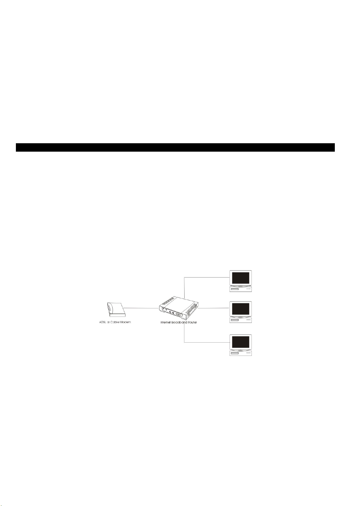
Applications:
Broadband Internet access:
Several computers can share one high-speed broadband connection (LAN and WAN-Internet).
Resource sharing:
Share resources such as printers, scanners and other peripherals.
File sharing:
Exchange data, messages, and distribute files thus making good use of hard disk space.
Online gaming:
Through the local area network, online gaming and e-commerce services can be easily setup.
With a broadband connection of 512K/64K through a NAT broadband sharing device, up to five (or eight) computers can get on the
Internet without any appreciable loss of speed. Both download and upload speeds work just fine. In addition, a built-in firewall
function—a security and anti-hacker system--can be activated. Such a low-cost but effective solution is scalable—adding more
computers are as simple as buying a hub or a switch and linking them through the uplink port.
- 1 -
Page 4

HARDWARE INSTALLATION
Hardware Requirements:
Broadband Sharing Device: Internet BroadBand Router.
Hub: Hub or switch depending on the number of computers.
Network adapter: Any standard Ethernet card (Ethernet NIC)
Network Cable: Ethernet UTP Cat. 5 (Type 5) cable; cable length depends on actual distances.
Broadband modem: ADSL Modem or Cable Modem provided by the ISP.
Parts Names and Functions
LED Status
Indicator Solid Flashing
Power
Status
Mail
Web
Link/ACT #
10/100
Port Functions
Uplink
Local #
WAN
Turns solid green when power is applied to this
device.
Lights up after system has booted successfully. Receiving/
N/A
Data transmitted or received at the rate of 100 Mbps Receiving/
Glows to indicate the Ethernet port is connected to a
computer, Hub or Switch.
Data transmitted or received at the rate of 100 Mbps Receiving/
Table 1: LED Indicators
Uplink to an Ethernet Switch/Hub.
RJ-45 dual-speed (10/100Mbps) auto-sensing ports for connecting to
either 10Mbps or 100Mbps Ethernet connections.
For connecting to an ADSL/Cable Modem device.
N/A.
Sending data
Incoming mail
Sending data through the WAN port.
Receiving/
Sending data through the Ethernet port.
Sending data
MDIX
Reset
DC 5V
Press to uplink to an Ethernet Switch/Hub.
Use a pin-shape item to push to reset this device to factory default
settings.
For connecting to the power adapter plug.
Table 2: Connections Ports
Hardware connections
1. Install the network card.
2. Connect the broadband modem (ADSL or Cable modem)
3. Connect the Internet Broadband Router (Internet BroadBand Router)
4. Check the installation.
- 2 -
Page 5
Install the network card
Each computer connected to the local area network has to have one Ethernet card.
1. Switch off the computer. Open the computer case. Plug in the network card into the
PCI or ISA slot.
2. Switch on the computer and install the drivers for the network card.
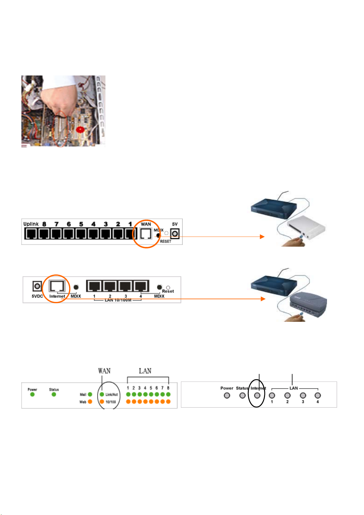
Connect the Internet BroadBand Router
Connect the Internet BroadBand Router with broadband modem (ADSL Modem or Cable Modem)
1. Plug in one end of the network cable to the WAN (Internet) port of the Internet
BroadBand Router.
【7 Port / 8 Port】
2. Plug in the other end of the network cable to the Ethernet port of the ADSL or Cable modem.
【4 Port】
Check the installation
【7 Port / 8 Port】
【4 Port】
z LED Indicators
LAN WAN
The control LEDs of the Internet Broadband Router are clearly visible and the status of the network link can be seen instantly:
1. With the power source on, once the device is connected to the broadband modem, the Power, Status, and WAN port link LEDs
of the Internet BroadBand Router will light up indicating a normal status.
2. If the WAN Port Link does not light up then press the MDIX button located on the underside of the unit.
- 3 -
Page 6
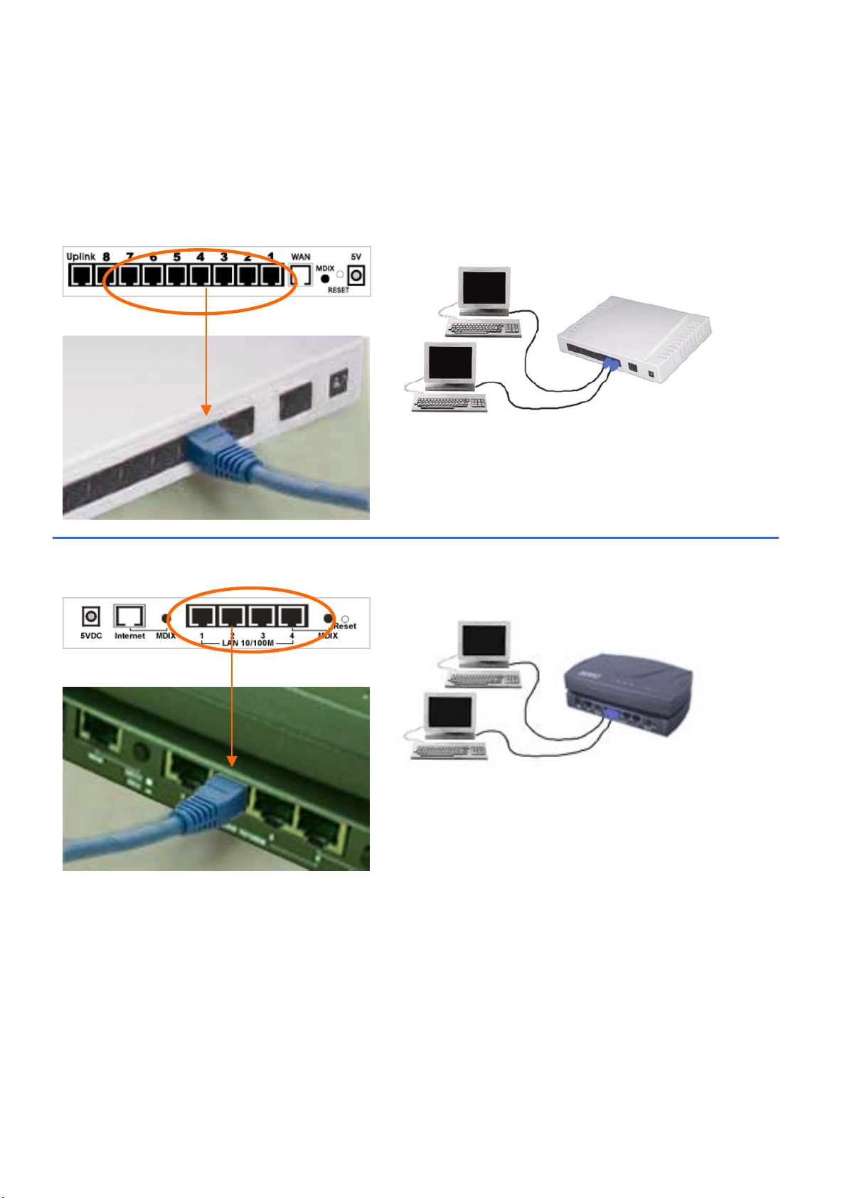
Connect the Internet BroadBand Router
Connect one end of the network cable to the Ethernet port on the computer; the other end of the cable connects to the LAN port of
the Internet BroadBand Router. Since the Internet BroadBand Router has five (or eight) ports, you can connect up to five (or eight)
computers directly to the unit. There you do not have to buy a hub to connect these computers since one Internet BroadBand Router
functions both as a connection-sharing unit and as a hub.
【7 Port / 8 Port】
Connect to the Broadband’s LAN Port with the
network cable. One device can connect with 5
【4 Port】
Connect to the Broadband’s LAN Port with the
network cable. One device can connect with 1
When the network connection is complete, you can check the connection status and speed by looking at the LAN port and Link
LED status. When both LEDs of a port are on, the connection is 100 Mbps (depending on your network card or cable). If only the
top LED is lighted, your network connection is only 10 Mbps. As long as the Link LED is on, then the connection is normal.
- 4 -
Page 7
CONFIGURATION
Network TCP/IP Settings:
The network TCP/IP settings differ based on the computer’s operating system (Win95/98/ME/NT/2000) and are as follows:
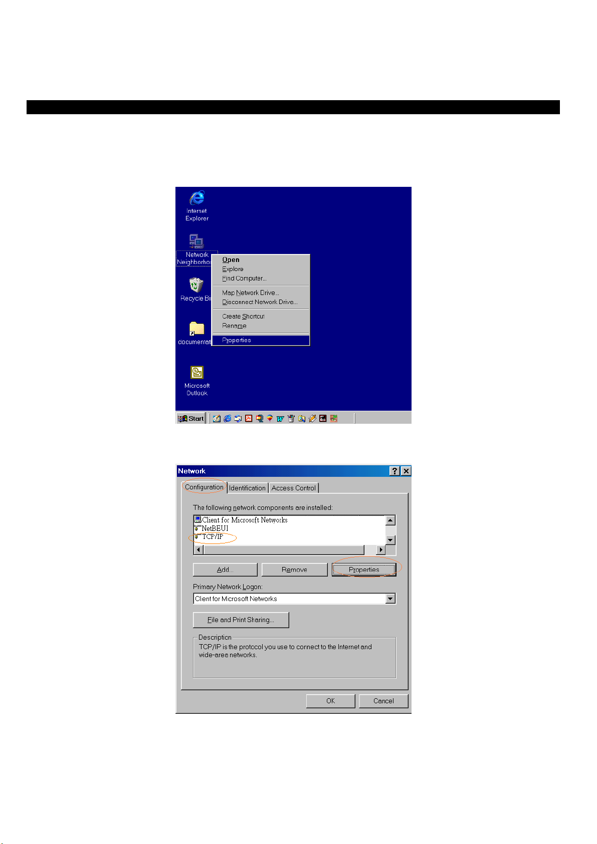
Windows 95/98/ME
1. Click on the “Network neighborhood” icon found on the desktop. Right click the button then select “Properties”.
2. In the Configuration window, select TCP/IP protocol then click Properties button to enter the TCP/IP setting screen
- 5 -
Page 8
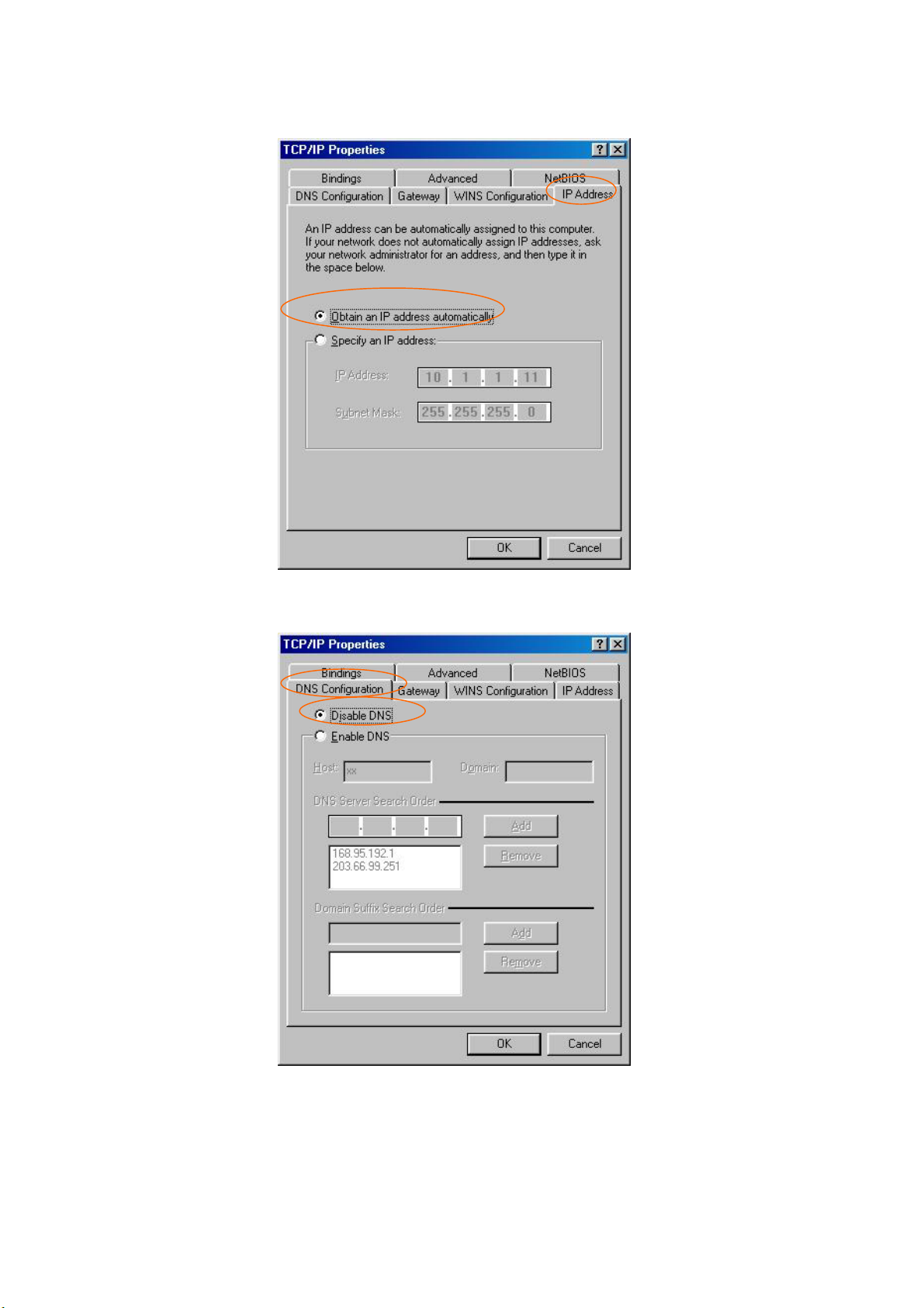
3. Choose the IP address tab, and then select Obtain an IP address automatically.
4. Choose the DNS Configuration tab, and then select Disable DNS.
- 6 -
Page 9
Windows 2000
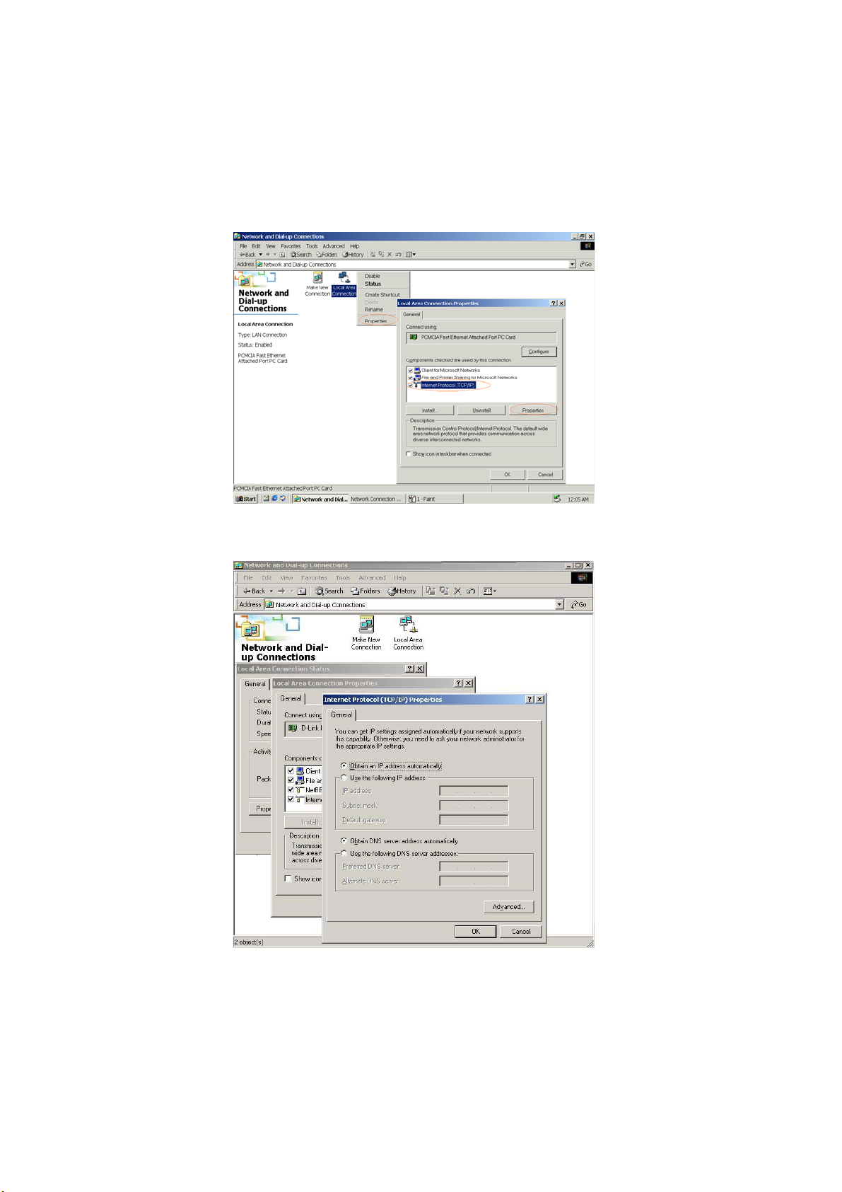
Double click on the “My computer” icon on the desktop. When “My computer” window opens, open the “Control panel” and
then open the “Network and Dialup Connections” applet. Double click on the “Local area network connection” icon. Select
“Properties” to enter the TCP/IP setting window.
1. In the “Local area network status” window, click on “Properties.” In the “Local area network connection” window, first
select TCP/IP setting and then select “Properties.”
2. Set both “IP address” and “DNS” to Automatic configuration.
- 7 -
Page 10
Windows NT4.0
Click on the “Start” button located on the lower left corner of the menu bar.
Select “Settings” and then “Control panel.”
In the “Control panel” window, select “Network” to enter the TCP/IP setting window.
1. Set “IP address” to “Obtain an IP address automatically.”
2. Set “DNS” to “Disable DNS.”
Internet Broadband Router Configuration
Please first make sure that the network connections are functioning normally.
The Cable modem LAN port is connected to the broadband sharing device’s WAN port with an RJ45 straight-through cable.
The LAN port of the Internet Broadband Router is also connected to the computer with an RJ 45 straight-through cable.
When the Internet Broadband Router is plugged in to a power source, the Link LED should light up. If the WAN Port Link LED
does not light up, please press the MDIX button on the underside of the unit.
LED Indicators
This Internet Broadband Router can be configured using Internet Explorer 4.0 or newer web browser versions.
1. Open Internet Explorer 4.0 or above Internet browser. In the network address source field, enter: http://192.168.1.1
factory-default IP address setting).
2. When the username and password dialog prompts, enter “admin” in both the username and password blanks to enter the main
configuration window.
3. For detailed and advanced setup, refer to the later chapter titled “Setting Up (Web Configuration)”.
(the
ADSL Dialup Configuration (ADSL PPPoE)
1. In the main web page, select “Quick Setup” and select “ADSL Dial-up User (PPPoE Enable).”
2. Enter your dialup account and password and then click the “OK” button.
Note that you should not run any PPPoE client software on the local workstations.
- 8 -
Page 11

Cable Modem Configuration
1. You do not have to setup the broadband sharing device. If you had changed the settings of the unit, select "Advanced Setup"
and then on the "Administration" click on "Reset Factory Settings" to restore factory defaults.
2. Some two-way broadband vendors have permanently set the Ethernet card address (MAC address). In that case, enter the MAC
address of the Ethernet card provided by your ISP vendor.
ADSL Leased Line Configuration
1. In the main web page, select “Quick Setup” and then click on the “Leased Line User (Specify an IP Address)”.
2. Enter the IP address, Netmask, Default Gateway, and DNS settings.
3. Click on “OK” when done.
The installation of your broadband sharing is now complete. You can now enjoy a broadband Internet connection shared with other
people.
- 9 -
Page 12

Setting Up (Web Configuration)
Before you configure this device, note that when the BroadBand Router is configured through an Ethernet connection, make sure
the host PC must be set on the IP subnetwork that can be accessed by the ADSL/Cable modem. For example, when the default
network address of the ADSL/Cable modem Ethernet interface is 192.168.1.x, then the host PC should be set at 192.168.1.xxx
(where xxx is a number between 2 and 254), and the default subnet mask is 255.255.255.0.
1. Enter IP address 192.168.1.1 to the URL web address location.
2. When the following dialog box appears,
Enter admin for User Name.
Enter admin for password.
Click OK.
3. In its home page, the left navigation pane where bookmarks are provided links you to the representative items to set up
appropriate parameters. You can select Quick Setup, PPPoE Setup, Administration, DHCP Server, Static Route,
Outgoing Policy, Incoming Policy, Virtual Server, Mapped IP, Special Application, DNS Proxy, Hacker Alert, Traffic
Log, Statistics or Software Update to setup.
4. Click each field to expand in the navigation pane. The fields covered in this utility are described as follows.
- 10 -
Page 13

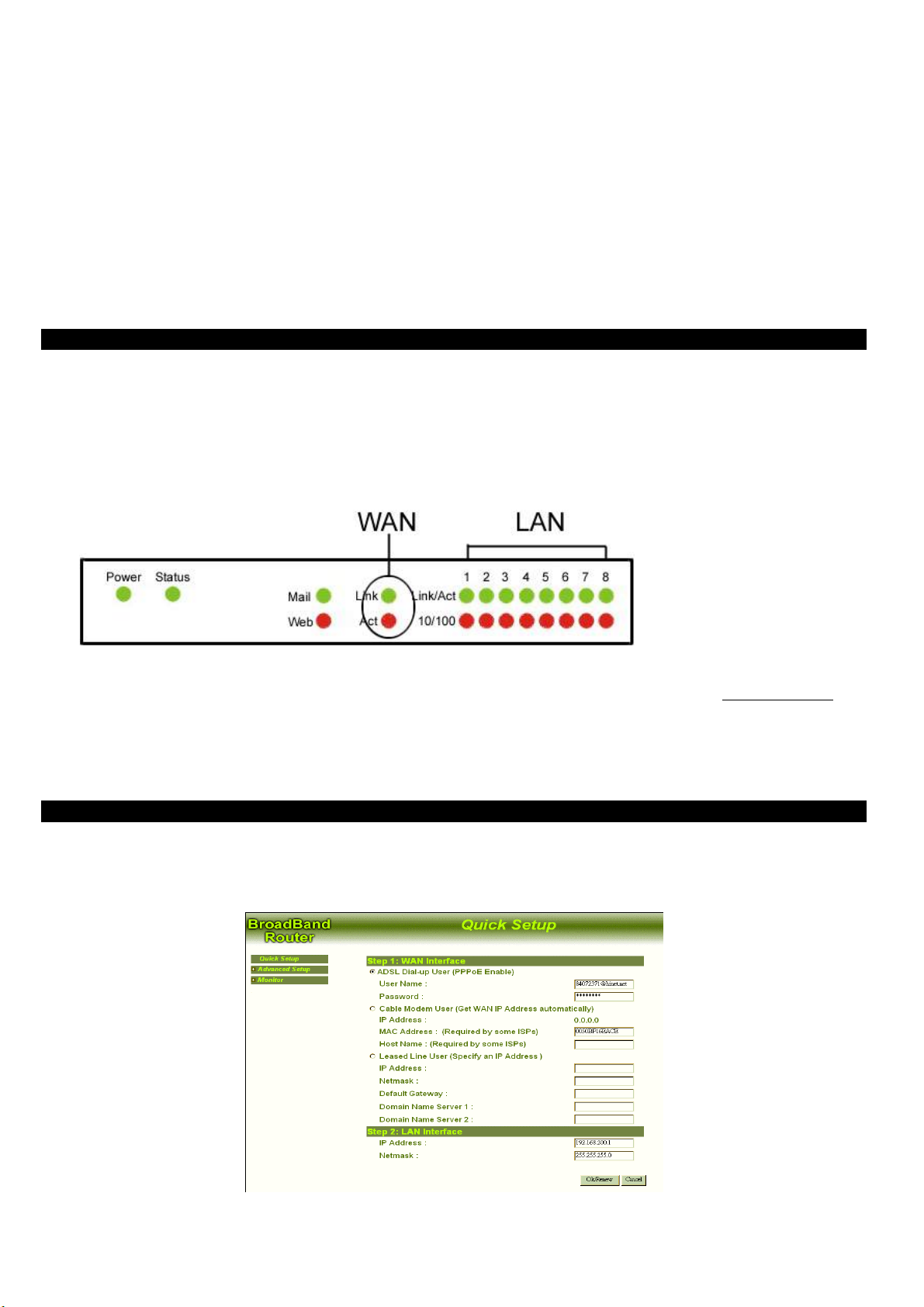
Quick Setup
WAN Interface
Select one of the following conditions that fit your case.
~ADSL Dial-up User (PPPoE Enable)
Some DSL-based ISPs use PPPoE to establish communications with an end-user. If you are connected to the Internet through a
DSL line, check with your ISP to see if they use PPPoE. If they do, you will have to select to enable it.
User Name: Enter User Name provided by your ISP.
Password: Enter Password provided by your ISP.
~Cable Modem User (Get WAN IP Address)
IP Address: If you are connected to the Internet through a Cable modem line with static IP address, enter the IP Address provided
by your ISP.
MAC Address: (Required by some ISPs) Some ISP may require your MAC address of your PC for identification.
Host Name: (Required by some ISPs) Some ISP may require the host name of your PC for identification.
- 11 -
Page 14

~ Leased Line User (Specify an IP Address)
If you are a leased line user with a fixed IP address, fill out the following items with the information provided by your ISP.
IP Address: (check with your ISP)
Netmask: (check with your ISP)
Default Gateway: (check with your ISP)
Domain Name Server 1: (check with your ISP)
Domain Name Server 2: (check with your ISP)
LAN Interface
IP Address: Enter the IP Address and Subnet Mask of internal LAN. The default value is 192.168.1.1
Netmask: Enter the Subnet Mask of internal LAN. The default Netmask is 255.255.255.0.
- 12 -
Page 15

Advanced Setup
PPPoE Setup
Click PPPoE to enter the PPPoE provided by your ISP or check the current status.
Current Status: Connected/Disconnected. (Read-only)
User name: Enter the user name provided by your ISP for PPPoE connection.
Password: Enter the password provided by your ISP for PPPoE connection.
Service: (Required by some ISPs): Enter the service name provided by your ISP.
IP Address provided by ISP: Select ~ Dynamic (allocated on connection) or ~ Fixed.
Service-On-Demand: Check this box and this device is configured to auto-connect whenever you log-on.
Auto-Disconnect if idle minutes: Enter a number as a predetermined period of time for auto-disconnection. This device can
then be configured to auto-disconnect from the Internet when there’s no activity on the line. To keep the line always connected, set
the number to 0.
Administration
Click Administration, the current administration information will appear on the screen.
Reset Configurations: Reset this device to the factory default settings.
Administrator Password: Set the password for adminstration purpose. It is recommended that you set the password and leave it in
a safe place.
Secondary Web Management Port of WAN Interface: Enter a new port number. For example, Port Number is 80. the
administrator enters http://xxx.xxx.xxx.xxx:80 on the broswer when accessing from WAN.
- 13 -
Page 16

Ping to WAN Interface:
Ping: Check this box to provide this device.
System Time Settings: The time that this device was set in factory may be different from your computer. However, you can
synchronize this device and your computer for accurate management purpose.
Synchronize system time with this client: Check this box to set this system synchronized with your computer.
DHCP Server
Click DHCP Server, and the following box appear on the screen.
If you setup this device as a DHCP Server, that will allow this BroadBand Router device to pass out dynamic IP addresses to your
local clients.
Enable DHCP Server Support: You may check to enable the DHCP server support for your local client to obtain dynamic IP
address.
When you select to distribute IP address to your local clients, you enter the MAC addresses of the local computer and the IP
addresses you assigned for them. Moreover, you can even add Comment to name your IP clients.
Enable DHCP Server Support
1. Click Enable DHCP Server Support.
2. Domain Name: Enter your domain name.
3. Domain Name Server 1: Your ISP will provide you with at least one DNS IP address. Enter the IP address of primary DNS.
4. Domain Name Server 2: Optional. Enter the IP address of primary DNS.
5. Client IP Address Range 1: Enter the first range of starting IP address and ending IP address, assigned to the LAN clients.
6. Client IP Address Range 2: Enter the second range of starting IP address and ending IP address, assigned to the LAN clients.
7. Static IP Address (Optional)
MAC Address: The MAC address of network interface card.
Fixed IP Address: The assigned IP address.
Comment: Explanation on the static IP address, ex. NAT100.
8. Click Ok to enable DHCP server support.
- 14 -
Page 17

Static Route
You can set a static route to manually administrate the network topology/traffic when dynamic routing is not effective enough.
Interface: Internal LAN.
Destination IP: IP address of the destination network.
NetMask: Sub-netmask of the destination network.
Gateway IP: The Gateway IP address of the destination network.
Configuration: Configure the static routing settings.
Add New Static Route
1. Click Static Route then click New Entry.
2. Enter Destination IP Address, Netmask and Gateway IP Address.
3. Click Ok to add a new static route.
Outgoing Policy
This BroadBand Router uses Outgoing Policy to filter outgoing packets. With Outgoing Policy, you can block specific internal
users from accessing the Internet. You can set up a filter against the IP Addresses.
- 15 -
Page 18

The Outgoing Policy settings are:
LAN IP: Source IP address of LAN port.
Protocol: Protocol type.
ANY: Any protocol including TCP, UDP and ICMP.
TCP: Transmission Control Protocol, corresponds to OSI layers 4 and 5, transport and session. TCP is a complete and
reliable data transmission control protocol and thus should be error free. Thus, during transmission, TCP has
added error-checking mechanisms to ensure data integrity. Compared to UDP, TCP is a connection-oriented, and
end-to-end protocol, it provides reliable, sequenced, and unduplicated delivery of bytes to a remote or local user.
UDP: User Datagram Protocol. UDP is a transport layer, connectionless mode protocol, providing a (potentially
unreliable, un-sequenced, and/or duplicated) datagram mode of communication delivery of packets to a remote or
local user. UDP transmission packets are sometimes lost and are not necessarily retransmitted. Applications using
UDP protocol normally count on simplicity and efficiency of network transmission and thus do not require the
complexity of TCP transmission to exchange data.
Port: Port number mapping to the internal IP address.
Action: Deny (block) or permit (forward).
Configure: You can select to modify or delete this filter.
Add Outgoing Policy
1. Click Outgoing Policy then click New Entry.
2. LAN IP: Enter IP address of the local computer.
3. Netmask: Select a specify Service port.
- 16 -
Page 19

4. Protocol: Click the down arrow () to select the appropriate protocol.
5. Port: Enter the range of the LAN user.
6. Action: Select DENY or ACCEPT to drop or forward packets from the specified IP address.
7. Click Ok to add a new Outgoing Policy.
Incoming Policy
This BroadBand Router uses Incoming Policy to filter incoming packets. You can set up a filter against the IP Addresses.
The Incoming Policy settings are:
Source IP: source IP address of WAN port.
Destination IP: IP address of the destination network (LAN port).
Protocol: protocol type.
ANY: any protocol including TCP, UDP and ICMP.
TCP: Transmission Control Protocol, corresponds to OSI layers 4 and 5, transport and session. TCP is a complete and
reliable data transmission control protocol and thus should be error free. Thus, during transmission, TCP has
added error-checking mechanisms to ensure data integrity. Compared to UDP, TCP is a connection-oriented, and
end-to-end protocol, it provides reliable, sequenced, and unduplicated delivery of bytes to a remote or local user.
UDP: User Datagram Protocol. UDP is a transport layer, connectionless mode protocol, providing a (potentially
unreliable, un-sequenced, and/or duplicated) datagram mode of communication delivery of packets to a remote or
local user. UDP transmission packets are sometimes lost and are not necessarily retransmitted. Applications using
UDP protocol normally count on simplicity and efficiency of network transmission and thus do not require the
complexity of TCP transmission to exchange data.
Port: port number mapping to the internal IP address.
Action: Deny (block) or permit (forward).
Configure: you can select to modify or delete this filter.
Add Incoming Policy
1. Click Incoming Policy then click New Entry.
- 17 -
Page 20

2. Source IP: Enter IP address of the local computer.
3. Netmask: Select a specify Service port.
4. Destination IP: Enter IP address of the destination network
5. Protocol: click the down arrow () to select the appropriate protocol.
6. Port: Enter the range of the LAN user.
7. Action: Select DENY or ACCEPT to drop or forward packets from the specified IP address.
8. Click Ok to add a new Incoming Policy.
Virtual Server
“Natural firewall” allows requests for Internet access from the Local network; however, requests from the Internet to the local
network are blocked. By setting Virtual Server, computers outside the Intranet are allowed to access specific ports.
Name: The service name provided by Virtual Server, or the pre-set application software. The server provides the following services:
Counter_Strike 、 Need_for_Speed_5 、 Battle_Isle 、 AOE_II_(Server) 、 Sudden_Strike 、 Red_Alert_II 、 Diablo_II 、
PC_Anywhere、Win_VNC、Netmeeting、Powwow_Chat、Baldurs_Gate_II.
Internal IP Address: The internal IP address for mapping to the service port.
Service Port: The range of the port number assigned for virtual server.
Configure: you can select to modify or delete this virtual server.
Add new Virtual Server
1. Click Virtual Server then click New Entry.
- 18 -
Page 21

2. Service Name: Name the service appropriately for easy identification, for example, HTTP.
3. Internal IP Address: Enter the internal IP address for mapping to the service port.
4. Pre-set Application: click the down arrow () to select the pre-set application that you want to be accessed through virtual
server.
5. Service port: The system will generate the range of the port number automatically based on the pre-set application selected.
Mapped IP
Mapped IP allows an internal computer to be exposed to unrestricted 2-way communication with other Internet users.
WAN IP: IP address of the WAN port.
LAN IP: IP address of the LAN port.
Configure: You can select to modify or delete the Mapped IP setting.
Add a Mapped IP
1. Click Mapped IP then click New Entry.
- 19 -
Page 22

2. WAN IP: IP address of the WAN port. (read-only)
3. LAN IP: Enter the local IP address mapping to the client computer.
4. Click Ok to add a new Mapped IP.
Special Application
NAT (Network Address Translation) function prohibits some applications, e.g. Internet games, Video conferencing, Internet
telephony, to work when multiple connections are required. Special Application, however, enables these applications to work in this
device. If Special Application is not enough for multiple applications to work correctly, try Mapped IP function as described in the
previous section.
Note: At any time, only one PC can use one Special Application tunnel.
Name: Name the application appropriately for easy identification. Or you may skip this field to next for a Pre-set Application.
Outgoing: The range of the outgoing packet's specified port numbers mapping to the pre-set application.
Incoming: The range of the incoming packet's specified port numbers mapping to the pre-set application.
Configure: You can select to modify or delete the special application setting.
Add a Special Application
1. Click Special Application then click New Entry.
- 20 -
Page 23

2. Application Name: Name the application appropriately for easy identification. Or you may skip this field to next for a Pre-set
Application.
3. Pre-set Application: click the down arrow () to select a pre-set application that you want to be accessed on the Internet.
4. Outgoing Destination Port: Enter the range of the outgoing packet's specified port numbers mapping to the pre-set application.
5. Incoming Destination Port: Enter the range of the incoming packet's specified port numbers allowed to pass this device.
6. When finished, click Ok to add a new special application.
DNS Proxy
The DNS Proxy caches some of the frequent used material from popular Web sites, saving access time, it also establish the domain
name and its corresponding IP address.
LAN IP Address: a specific IP address on LAN.
Domain Name: A specific computer name on LAN referred to the above IP address.
Configuration: Modify: click this to modify the DNS Proxy configuration.
Delete: click this to delete DNS service.
NOTE
1. To use the DNS Proxy service, the client computer’s Domain Name Server 1 configuration must direct to this broadband
router.
2. For Cable Modem Users with static IP address or for ADSL Leased Line Users, to connect to the Internet, you should enter
the external DNS server’s IP address manually in Quick Setup page’s Domain Name Server.
3. In DHCP Server page’s Domain Name Server, you need to set up the same IP address referred to the broadband router.
- 21 -
Page 24

Add a DNS Proxy
Click DNS Proxy then click New Entry.
LAN IP Address: Enter an IP address on LAN for this DNS Proxy.
Domain Name: Enter a computer name referred to the above IP address.
Note: You must enter a Domain Name with the standard format, for example: abc.ipsharing.xyz.tw or abc.ipsharing.xyz.
Hacker Alert
Hacker Alert provides you with the opportunity to maintain regular checks against hacking attacks.
Detect SYN Attack: To detect whenever a hacker intends to overwhelm an Internet server with connection requests that cannot
be completed. By sending the host a high volume of SYN (synchronization) packets, it causes the server to become so busy
attempting to respond to the attack that it ignores legitimate requests for connections. Check this box to set the number of SYN
Flood packets that are allowed to pass the firewall.
Detect ICMP Flood: To detect whenever a hacker sends packets of PING continuously to each port of LAN by broadcasting.
Check this box to set the number of ICMP Flood packets that are allowed to pass the firewall.
Detect UDP Flood: To detect whenever a hacker sends packets of PING continuously to each port of LAN by broadcasting.
Check this box to set the number of UDP Flood packets that are allowed to pass the firewall.
Detect Ping Of Death Attack: To detect whenever a hacker sends a packet that is substantially larger than the usual 64 bytes
over the Internet via the ping protocol to a remote computer. The size of the packet causes the computer to crash or reboot.
Detect Port Scan Attack: To detect whenever a hacker intends to attack a Port ID that is sensitive to the Port Scan attack.
E-mail Alert
SNMP Server: Set the SNMP Server.
E-mail Address: Set the e-mail address.
- 22 -
Page 25

Software Update
1. First you can obtain the version number of current software from Software Version.
2. Ask your local distributor to get the newest software's updated version.
Download and store the updated program into the server's hard disk.
3. Click Browse button under Software Update to enter the Selecting File window and choose the most updated software
version.
4. Click Ok on the bottom of the screen to update the software.
Warning: If you set [Reset Factory Settings] to Yes and click [Ok], you will clear all of the device settings. Do not reset to the
factory settings unless you have some problems with this device. Once the BroadBand Router is reset, you will have to re-enter
your configuration information.
Monitor
Connection Log
Select Connection Log to view the connection status of PPPoE or DHCP Client.
Time: The starting time for the connection.
Connection Log: The source IP address and port number.
- 23 -
Page 26

Traffic Log
Select Traffic Log to view traffic history of incoming and outgoing packet.
Time: The starting time for the connection.
Source: The source IP address and port number.
Destination: The destination IP addresses.
Duration: The time slot for the connection.
Services: The content of the connection.
Per User Statistics
Select Per User Statistics to view the total packets transmitted and received by the local ports and ranked it by the number of
packets.
LAN IP: IP address of the LAN port.
Tx: The number of packets transmitted on this port.
Rx: The number of packets received on this port.
Total: The amount of packets transmitted and received on this port.
Average (/sec): The average value of packets transmitted and received.
Utilization: The percentage of current bandwidth used on this port.
- 24 -
Page 27

Statistics
Press Statistics to view the traffic flow for the past 24 hours.
X-axis: traffic statistics (Kbytes/Sec)
Y-axis: time (hour).
Status
Display the current status of the Broadband Router. (Read-only)
Software Version: The Software version of this Broadband Router.
LAN
MAC Address: The MAC address of network interface card.
IP Address: IP address of the LAN port.
Netmask: The Subnet Mask of the LAN port.
DHCP Server: The DHCP status of the port.
WAN
MAC Address: the MAC address of network interface card.
IP Address: IP address of the WAN port.
Netmask: The Subnet Mask of the WAN port.
- 25 -
Page 28

Default Gateway: The default IP address of the gateway.
Domain Name Server 1: IP address of the primary DNS server.
Domain Name Server 2: IP address of the secondary DNS server.
DHCP Client Table
MAC Address: The MAC address of network interface card.
IP Address: IP address assigned to DHCP client.
- 26 -
Page 29

FAQ
Q1: Why can’t I still connect to the network when I have already installed and connected all the equipment?
1. Make sure that the Cable/xDSL Router is properly connected to the Internet BroadBand Router, the power is switched on, and
all networking equipments are installed as instructed in the manual.
2. Verify that your computer and the Internet BroadBand Router have the same network address. If you are not sure about this, set
your PC’s IP address to “automatically configure IP address” so that it can obtain an IP address from the DHCP server.
3. Check that your PC’s network settings are set correctly—including default gateway (192.168.1.1), DNS, IP address, and others.
Your PC’s IP address has to be within the internal network’s range of addresses (192.168.1.2 to 192.168.1.254).
4. If you were originally using a dial-up connection, you have to reset your IE properties. Perform the following steps.
a. Go to Desktop, right-click Internet Explorer, click propertiesÆConnectionsÆSetup.
b. In the Internet Connection Wizard, select “I want to set up my Internet connection manually, or I want to connect through
a local area network (LAN).”
c. Click Next.
d. Select “I connect through a local area network. (LAN)
e. Follow the on-screen instruction to proceed. When done, select “Finish” to complete.
5. Check the settings of your Internet BroadBand Router. If the information entered is different than that provided by your ISP or
the interface settings are wrong, please enter the correct settings.
6. Read the installation manual.
7. If after following the above steps you are still unable to connect to the network, please call your vendor’s customer service.
Q2: Why can’t I automatically connect to the network when I open my browser?
1. Check your network connection and make sure that the power is on, the status LEDs are normal, and the Web LED blinks.
2. Verify the settings of the Internet BroadBand Router. Check the settings of the external network interface.
3. Deactivate the proxy server settings in your browser.
4. If after following the above steps a connection is not automatically established when your browser, please call your vendor’s
customer service.
Q3: Can I use ICQ with the Internet BroadBand Router? Do I have to change any settings?
You can use ICQ without having to specially configure the Internet BroadBand Router.
Q4: Why is it that when my PC’s network card is connected to the Internet BroadBand Router, only the Link LED is lit?
The “10/100” Link LED is lit only with a 100Mbps transmission rate. If only the Link LED is lit, this means that your network card
is connected at 10Mbps.
- 27 -
Page 30

Q5: What’s a MAC address?
Each network interface card has a unique address (a hexadecimal value). The first three bytes are the manufacturer’s code while the
last three bytes are the network card’s number. In a connected network, each network has its own addressing scheme to facilitate
routing and to allow setting of different networks.
Q6: What is a subnet mask?
A subnet mask, or netmask, is like an IP address. When the subnet mask is used with the IP address, your PC's network domain can
be identified. The IP address can be divided into Classes and is different from the network mask. (See Table below)
IP address Classes Network Mask
Class A
Class B
Class C
255.0.0.0 255.255.0.0 255.255.255.0
Q7: What’s the difference between TCP and UDP?
TCP is a complete and reliable data transmission control protocol and thus should be error free. Thus, during transmission, TCP has
added error-checking mechanisms to ensure data integrity. UDP on the other hand, is much simpler. UDP transmission packets are
sometimes lost and are not necessarily retransmitted. Applications using UDP protocol normally count on simplicity and efficiency
of network transmission and thus do not require the complexity of TCP transmission to exchange data.
Q8: What is DHCP? Do I have to enable DHCP?
1. For networks using a fixed IP address, the network administrator has to know and set every IP address for each user. This
method may result in duplication of IP addresses. Moreover, the network administrator has to manually set the IP address of
every machine on the network. The Dynamic Host Configuration Protocol (DHCP) service is provided by a DHCP server to
store, manage, and dynamically allocate IP address. Users can thus automatically get their IP addresses without having to
manually set it.
2. It is not necessary to enable DHCP. Based on the explanation above, however, you must be careful in setting IP addresses
manually. IP address duplication, if not prevented, can lead to networking errors.
Q9: What’s the difference between a virtual computer and a virtual server?
A virtual server is a computer that can receive specific packets. Functionally, this means that an internal network can have a special
computer functioning as a web, FTP, DNS, or mail server. A virtual computer offers complete IP functionality—this computer can
provide network services. In other words, a virtual server has only some special communication ports open while a virtual computer
has all its ports open.
Q10: If I reset to factory defaults, do I lose all my changes?
Yes. All changes that you had made will be replaced by the factory defaults.
Q11: When the LAN ports are used up, how can I connect more computers to the Internet BroadBand Router?
You can use a hub or a switch to connect with the LAN port. A switch can be stacked with additional switches.
Q12: What’s the difference between the Internet BroadBand Router and an ordinary hub/switch?
An ordinary hub only transmits packets but the Internet BroadBand Router not only functions as a hub but also as a switch and has
a NAT function that allows one external IP address to be shared by several computers—a multi-functional box.
- 28 -
Page 31

Q13: Can I use one Internet BroadBand Router to play online games?
Yes. Several users can play online games simultaneously.
Q14: Aside from MS Windows operating systems, can I also connect computers running other operating systems (Unix, Linux, etc.)
to the Internet BroadBand Router?
Yes. The Internet BroadBand Router can be used by any operating system that supports TCP/IP protocols.
Q15: Does the Internet BroadBand Router have other functions?
Aside from the basic NAT IP share function, the Internet BroadBand Router has other functions to help in network management
such as DHCP service, fixed routing, control rules, virtual sever, virtual computer, packet log, and transmission rate statistics. Your
Internet BroadBand Router is not just a bandwidth-sharing device—it is a multi-functional and easy-to-use firewall.
Q16: How do I check if my computer uses a static or dynamic IP address?
Open an MS-DOS console window and enter the following command “C:\>ipconfig /all” to see if your computer is using a DHCP
server. If the display shows that such a server is being used, then you have a dynamically assigned IP address, otherwise, your IP
address is static.
Q17: How many computers can be connected to the Internet BroadBand Router?
The Internet BroadBand Router supports a Class B addresses. If the DHCP server is not used (with a maximum of 253 IP addresses)
and network restrictions are lifted, then theoretically, up to 64,514 (255 x 253 – 1) IP addresses can be used if set manually. This
number is also the maximum number of computers that can be connected.
Q18: I can’t successfully install the Internet BroadBand Router, what should I do?
Installation failure can be due to many things—narrow down the possibilities to either a software or a hardware problem. If it’s a
hardware problem, then check if all equipment has been installed according to the installation manual. If the LEDs for the WAN
and Link ports of the Internet BroadBand Router are not lit, please press the MDIX button on the underside of the unit. If the LEDs
appear normal, check your network settings; for example, the connected computer should be set to an automatically assigned IP
address. If the problem persists, please contact your vendor’s customer service.
Q19: Can I use the Internet BroadBand Router to set up my own server?
You can. You first have to make sure that you have a valid static IP address. All the “Virtual server” services provided by the
Internet BroadBand Router such as web, DNS, Mail, FTP, and others can be accessed through the network.
Q20: How much memory does the Internet BroadBand Router have?
The Internet BroadBand Router has 8 MB of onboard memory and a 2 MB flash memory.
Q21: Can I use the Internet BroadBand Router with firewalls from other vendors?
To avoid unnecessary network conflicts, the Internet BroadBand Router is normally installed behind a firewall and will take up one
IP address from the firewall. This IP address will be used by the Internet BroadBand Router for computers connected to it—a single
IP shared by many users.
Q22: What’s the difference between a LAN and a WAN?
A LAN is an internal network interface that can reach transmission rates of up to 100 Mbps. A WAN is an external interface to the
Internet whose speed depends on the connection provided by your Internet service provider (ISP).
- 29 -
Page 32

Q23: Can I check the address of my network interface card?
There are two ways. One way, if you’re using a dynamic IP address, is to open the Internet BroadBand Router’s configuration page
and in the “Statistics” field, select “system status” to check the binding of your computer’s IP address to the network card’s MAC
address. Another way is to open an MS-DOS console and then run the command “C:\>ipconfig /all” to check the MAC address.
Q24: What network cables should be used to connect to the Internet BroadBand Router?
Please use Ethernet UTP RJ-45 cables to connect to the Internet BroadBand Router.
Q25: Can I use the Internet BroadBand Router to connect with other computers in my private network?
You can. You have to connect the WAN port to the hub or switch and then, using the configuration interface, set the Internet
BroadBand Router’s “external network interface” to manually set IP addresses (If your external network has a DHCP server, you
can set this to “cable modem user” to automatically get an IP address). Finally, make sure that the “LAN interface” has a different
subnetmask address from the “external network interface” to avoid network conflicts.
Q26: What is the Special Application function?
Some online games cannot be used through the Internet BroadBand Router without having to set first the “Special Application”
function of the Router. Mapping for UDP Port/TCP Port to the Local Port of the virtual IP address lets your computer look up
online game partners or allows others to join in locally sponsored games—you can play right after properly setting up the ports. If
there are some game settings that we have not included, please use the “Traffic Log” function to look at what ports your online
game uses and then set the ports in the “Special Application” setting.
Q27: What’s the use of the RESET button at the rear panel of the Internet BroadBand Router?
If for any reason, e.g. unexpected problem or inappropriate manual operation that cause the Internet BroadBand Router to
malfunction, you have to reset this device to factory default settings. While executing this function, be careful the current settings
will be lost. Please also note that if you reset to default settings, the user’s name and password will be reset to admin.
Q28: What’s the use of the MDIX button at the rear panel of the Internet BroadBand Router?
After connected to an ADSL/Cable modem or a Hub/Switch, the LINK LED corresponding to the WAN Port will be lit to show a
successful connection. If it fails to lit, press the MDIX button, the connection will then be successful.
- 30 -
 Loading...