


International Rectifier ST280S04P1VL, ST280S04P1V, ST280S04P0VL, ST280S04P0V, ST280S04M2VL Datasheet
...
DISCRETE POWER DIODES and THYRISTORS
DATA BOOK
280A
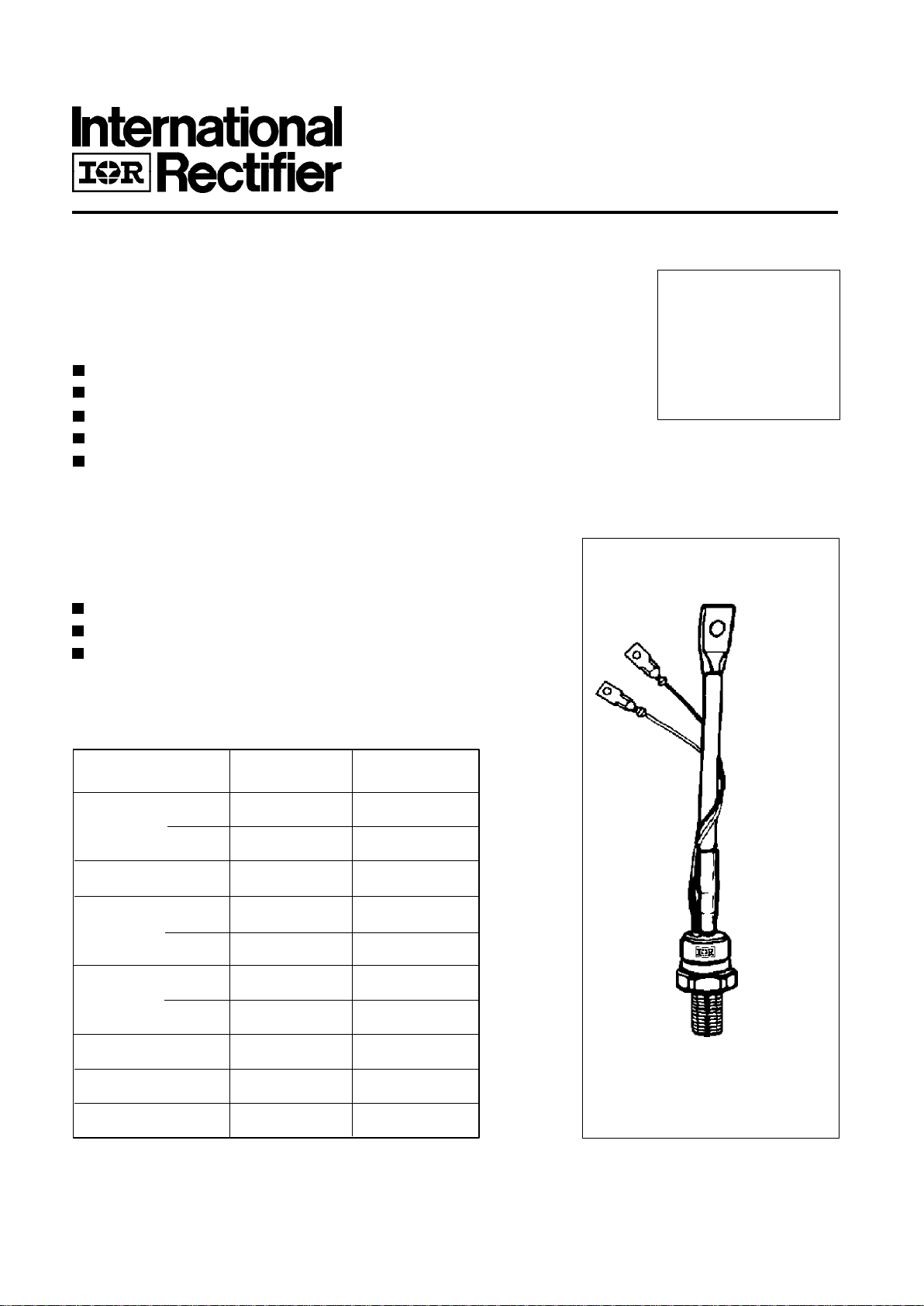
PHASE CONTROL THYRISTORS Stud Version
ST280S SERIES
Bulletin I25161/B
Features
Center amplifying gate
Hermetic metal case with glass-metal seal insulator
International standard case TO-209AB (TO-93)
Threaded studs UNF 3/4 - 16UNF2A or ISO M16x1.5
Compression Bonded Encapsulation for heavy duty
operations such as severe thermal cycling
Typical Applications
DC motor controls
Controlled DC power supplies
AC controllers
I
T(AV)
280 A
@ T
C
85 °C
I
T(RMS)
440 A
I
TSM
@ 50Hz 7850 A
@ 60Hz 8220 A
I
2
t @ 50Hz 308 KA2s
@ 60Hz 281 KA
2
s
V
DRM/VRRM
400 to 600 V
t
q
typical 100 µs
T
J
- 40 to 125 °C
Parameters ST280S Units
Major Ratings and Characteristics
case style
TO-209AB (TO-93)
ST280S Series
2222222222222
12
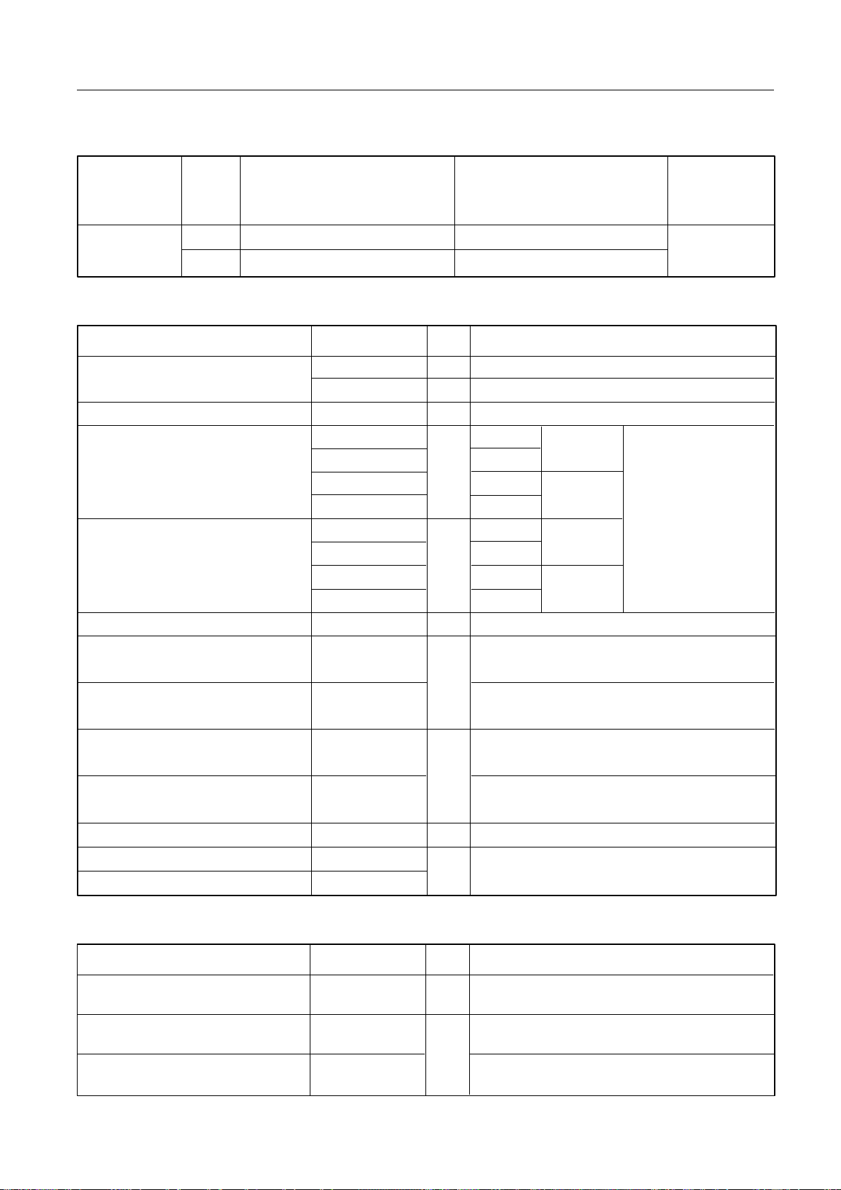
di/dt Max. non-repetitive rate of rise Gate drive 20V, 20Ω, tr ≤ 1µs
of turned-on current T
J
= TJ max, anode voltage ≤ 80% V
DRM
Gate current 1A, dig/dt = 1A/µs
V
d
= 0.67% V
DRM, TJ
= 25°C
I
TM
= 300A, TJ = TJ max, di/dt = 20A/µs, VR = 50V
dv/dt
= 20V/µs, Gate 0V 100Ω, tp = 500µs
Parameter ST280S Units Conditions
1000 A/µs
Switching
t
q
Typical turn-off time 100
t
d
Typical delay time 1.0
On-state Conduction
ELECTRICAL SPECIFICATIONS
Voltage Ratings
µs
I
T(AV)
Max. average on-state current 280 A 180° conduction, half sine wave
@ Case temperature 85 °C
I
T(RMS)
Max. RMS on-state current 440 A DC @ 75°C case temperature
I
TSM
Max. peak, one-cycle 7850 t = 10ms No voltage
non-repetitive surge current 8220 t = 8.3ms reapplied
6600 t = 10ms 100% V
RRM
6900 t = 8.3ms reapplied Sinusoidal half wave,
I
2
t Maximum I2t for fusing 310 t = 10ms No voltage Initial TJ = TJ max.
220 t = 8.3ms reapplied
218 t = 10ms 100% V
RRM
200 t = 8.3ms reapplied
I
2
√t Maximum I2√t for fusing 3100 KA2√s t = 0.1 to 10ms, no voltage reapplied
V
T(TO)1
Low level value of threshold
voltage
V
T(TO)2
High level value of threshold
voltage
r
t
1
Low level value of on-state
slope resistance
r
t
2
High level value of on-state
slope resistance
V
TM
Max. on-state voltage 1.28 V Ipk= 880A, TJ = TJ max, tp = 10ms sine pulse
I
H
Maximum holding current 600
I
L
Max. (typical) latching current 1000 (300)
0.84 (16.7% x π x I
T(AV)
< I < π x I
T(AV)
), TJ = TJ max.
0.50 (16.7% x π x I
T(AV)
< I < π x I
T(AV)
), TJ = TJ max.
0.47 (I > π x I
T(AV)
),TJ = TJ max.
Parameter ST280S Units Conditions
0.88 (I > π x I
T(AV)
),TJ = TJ max.
KA2s
V
mΩ
mA T
J
= 25°C, anode supply 12V resistive load
A
Voltage V
DRM/VRRM
, max. repetitive V
RSM
, maximum non- I
DRM/IRRM
max.
Type number Code peak and off-state voltage repetitive peak voltage
@ TJ = TJ max
V V mA
04 400 500
06 600 700
ST280S 30