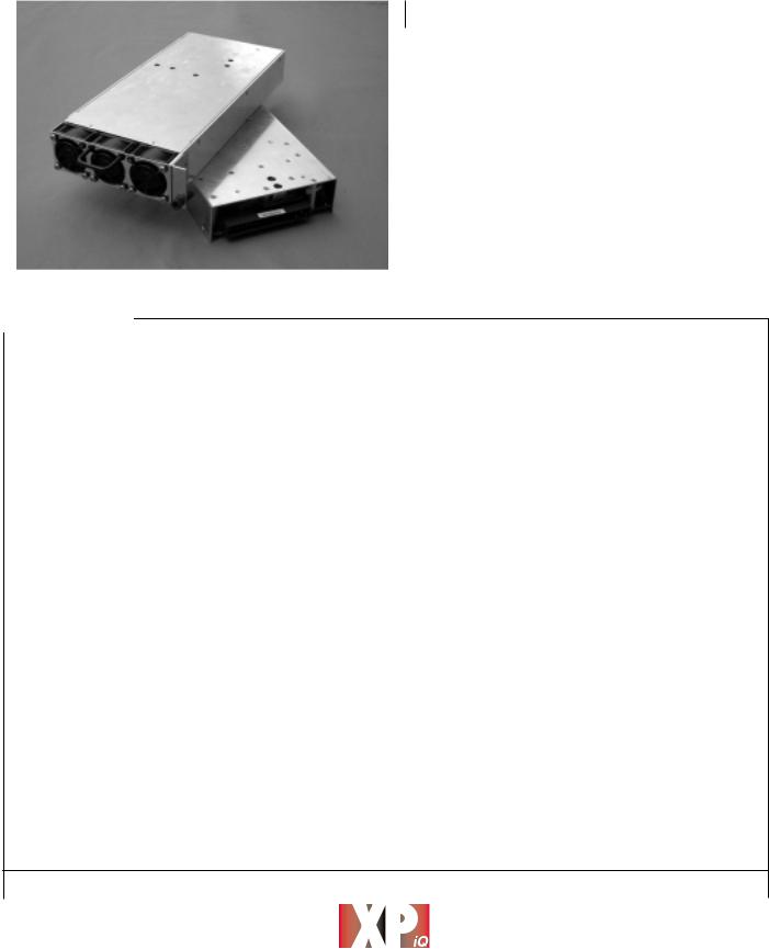
International Power Sources ZCA8CPS12C, ZCA8CPS12CI, ZCA8CPS12CM, ZCA8CPS12CR, ZCA8CPS12I Datasheet
...
AC/DC Front End
|
|
|
|
|
800 Watts |
|
|
XPiQ inc. |
|
ZC8 Series |
|
|
Intelligent Design Quality Product |
|
|
|
|
||
|
|
|
|
|
|
• |
Hot Swap or Chassis Mount |
|
|
|
Front End Switcher |
|
||
|
|
|
|
|
|
|
|
• |
|
|
|
|
Optional 3 Bay / 1U High Rack for |
|
|
|
|
Hot-Swap 2+1 Redundant Operation |
|
|
|
|
• |
|
|
|
|
Active PFC - Meets EN61000-3-2, -3 |
|
|
|
|
• |
|
|
|
|
World Wide Safety Approvals & CE Mark |
|
|
|
|
• |
|
|
|
|
OR’ing Diodes Standard on all Models |
|
|
|
|
• |
|
|
|
|
Single Wire Current Share |
|
|
|
|
|
|
Specification
Input
AC Input Voltage |
• |
85-264 VAC |
Input Frequency |
• |
47-63 Hz |
Power Factor |
• |
0.99 |
Inrush Current |
• Limited to 30 A peak |
|
Input Protection |
• Internal 20 A fuse |
|
Output
Output Voltage |
• 12, 24 or 48 VDC with 5 VSB |
|
|
|
at 250 mA |
Output Power |
• |
650-800 W |
Output Voltage |
• |
±5% min |
Adjustment |
|
|
Minimum Load |
• No minimum load for all outputs |
|
Line/Load Regulation |
• |
±2% |
Ripple & Noise |
• |
1% pk-pk maximum |
Transient Response |
• 4% max deviation, 300 µs recovery |
|
|
|
time for a 25% load change |
Temperature |
• |
0.02%/°C |
Coefficient |
|
|
Hold Up Time |
• |
20 ms minimum |
Remote Sense |
• Up to 0.25 V compensation |
|
Overvoltage |
• |
Latched shutdown, recycle |
Protection |
|
input to reset |
Overcurrent |
• Standard with auto recovery |
|
Protection |
|
|
Overtemperature |
• Logic high signal for overtemp |
|
Protection |
|
conditions |
Current Sharing |
• |
±10% |
General
Efficiency |
• 75-85% typical at full load |
MTBF |
• 200,000 hrs per Bellcore |
Isolation Voltage |
• 3000 VAC Input to Output |
|
1500 VAC Input to Ground |
|
500 VAC Output to Ground |
Signals |
• DC OK = Logic Low |
|
AC Fail = Logic High |
|
Global Inhibit = Logic Low |
|
Enable = Logic Low |
|
Overtemp = Logic Hi |
LED Indicators |
• 2 status indicators |
Size |
• 5.0” x 10.0” x 1.6” |
Weight |
• 2.9 lbs. (1.3 kgs.) |
Environmental
Operating |
• |
0°C to +70 C, full power to +50 °C |
Temperature |
|
derate from +50 °C to 70 °C |
|
|
at 2.5%/°C |
Cooling |
• |
Internal ball bearing fans |
Humidity |
• |
<95% RH, non-condensing |
Storage Temperature |
• |
-40 °C to +85 °C |
EMC & Safety
Safety Approvals |
• UL1950, CSA C22.2 No 950, |
|
|
|
EN60950 CE Mark LVD |
EMC |
• |
EN61000-3-2, -3, EN55022 and FCC |
|
|
20780 part 15J Class B conducted |
Immunity & Surge |
• |
Meets EN61000-4-4, -5 |
• |
|
PH: 508 |
429.9883 |
• |
||
|
||||||
|
||||||
|
|
|
|
FAX: 800 |
226.2100 |
|
|
www.XPiQ.com |
|
|
Email: sales@xpiq.com |
|
|
|
|
|
Holliston, MA 01746 USA |
|
||
|
|
|
|
|||

OUTPUT VOLTAGE & CURRENT RATINGS |
|
|
ZC8 |
||
Package |
Maximum |
|
Output |
Maximum |
Model |
Style |
Power |
|
Voltage |
Amps |
Number |
|
650 W |
|
12.0 V |
54.2 A |
ZCA8HPS12 |
Hot Swap |
700 W |
|
24.0 V |
29.2 A |
ZCA8HPS24 |
|
800 W |
|
48.0 V |
16.7 A |
ZCA8HPS48 |
|
650 W |
|
12.0 V |
54.2 A |
ZCA8CPS12 |
Chassis Mount |
700 W |
|
24.0 V |
29.2 A |
ZCA8CPS24 |
|
800 W |
|
48.0 V |
16.7 A |
ZCA8CPS48 |
Hot Swap with Front Panel |
480 W |
|
12.0 V |
40.0 A |
ZCA8HPS12C |
525 W |
|
24.0 V |
21.9 A |
ZCA8HPS24C |
|
IEC-320 Inlet with Switch |
|
||||
600 W |
|
48.0 V |
12.5 A |
ZCA8HPS48C |
|
|
|
||||
Chassis Mount with Front |
480 W |
|
12.0 V |
40.0 A |
ZCA8CPS12C |
Panel IEC-320 Inlet |
525 W |
|
24.0 V |
21.9 A |
ZCA8CPS24C |
with Switch |
600 W |
|
48.0 V |
12.5 A |
ZCA8CPS48C |
Notes
1 Part numbers in bold type are standard stock models, all others including options below are build to order.
2. |
Standard airflow is front to rear. For optional reverse airflow add suffix R to the part number. Derate rear input models 20%, front panel IEC-320 inlet |
|
models 16.6%. |
3. |
Optional I2 C function by adding the suffix I to the part number. |
4. |
Optional reverse airflow and I2C function by adding the suffix M to the part number. Derate rear connector models 20%, front panel IEC-320 inlet |
• |
models 16.6%. |
|
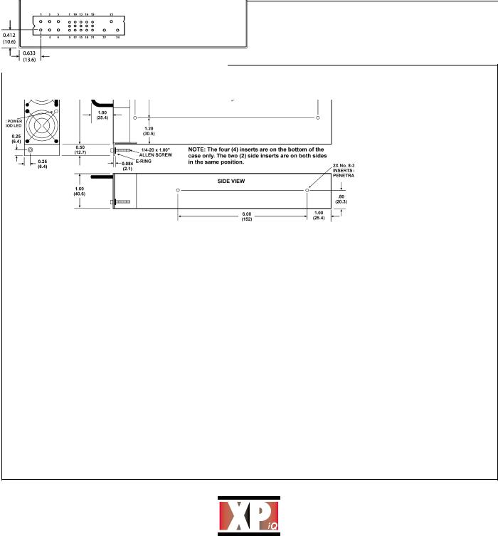
Mechanical Details - Power Supply
Notes:
1. Hot swap models are illustrated in the mechanical drawing.
Chassis mount models do not have handle or mounting bracket with thumb-screw.
2. For unit to operate, Enable Pin (Pin 7) must be at logic LO or shorted to Pin 9.
3. For proper operation all output pins (1-3) should be connected together, Also, all returns pins (4-6) should be connected together.
4. Pins 11, 12, 14, 17 & 19 functions are only present with I2C option.
5. Dimensions shown in inches (mm).
6. Vertical blackplane mounting may not allow for sufficient airflow. Horizantal backplane, or additional spacing with a vertical backplane is recommended.
|
|
|
|
|
|
Pin Connections |
|
||
|
|
|
|
Pin |
Function |
Pin |
Function |
||
|
|
|
|
1 |
+V Out |
13 |
Module Present |
|
|
|
|
|
|
2 |
+V Out |
14 |
DC Power Good/Add GA1 |
||
|
Connector: Positronics PCIB24W9M400A1 |
|
|
3 |
+V Out |
15 |
AC Power Fail |
|
|
|
|
|
|||||||
|
Mate: PCIB24W9F400A1 |
|
|
4 |
V Return |
16 |
V Trim |
|
|
|
Note: Output Connector is flush with the end of the case |
|
|
5 |
V Return |
17 |
Overtemp. Warning/Add GA0 |
||
6 |
V Return |
18 |
Current Share |
||||||
|
±0.040 (1.02). |
|
|
||||||
|
|
|
7 |
Enable |
19 |
Current Monitor/Add GA2 |
|||
|
|
|
|
||||||
|
|
|
|
8 |
+Sense |
20 |
+5V Standby |
||
|
|
|
|
9 |
-Sense |
21 |
Standby Return |
||
|
|
|
|
10 |
Inhibit |
22 |
Chassis Ground |
||
|
|
|
|
11 |
Spare/SDA |
23 |
AC Line |
||
|
|
|
|
12 |
Spare/SCL |
24 |
AC Neutral |
||
|
|
|
|
|
|
|
|
|
|
www.XPiQ.com
PH: 508 429.9883
FAX: 800 226.2100 Email: sales@xpiq.com Holliston, MA 01746 USA
 Loading...