

International comfort products R4AE Series, R−410A Installation Instructions Manual
INSTALLATION INSTRUCTIONS
R−410A, 50 Hz Split System Air Conditioner
Product Family: R4AE
These instructions must be read and understood completely before attempting installation.
Safety Labeling and Signal Words
DANGER, WARNING, CAUTION, and
NOTE
The signal words DANGER, WARNING,
CAUTION, and NOTE are used to identify levels of
hazard seriousness. The signal word DANGER is
only used on product labels to signify an immediate
hazard. The signal words WARNING, CAUTION,
and NOTE will be used on product labels and
throughout this manual and other manuals that may
apply to the product.
DANGER − Immediate hazards which will result in
severe personal injury or death.
WARNING − Hazards or unsafe practices which
could result in severe personal injury or death.
CAUTION − Hazards or unsafe practices which
may result in minor personal injury or product or
property damage.
NOTE − Used to highlight suggestions which will
result in enhanced installation, reliability, or
operation.
Signal Words in Manuals
The signal word WARNING is used throughout this
manual in the following manner:
WARNING
!
The signal word CAUTION is used throughout this
manual in the following manner:
!
Signal Words on Product Labeling
Signal words are used in combination with colors
and/or pictures on product labels.
WARNING
CAUTION
IP24
(048 & 060 sizes only)
TABLE OF CONTENTS
Safety Considerations 2...........................
Installation 3.....................................
Unit Support 3...................................
Location 3.......................................
Clearances 4....................................
Refrigeration System 4...........................
Electrical Connections 4..........................
Start−up Procedure 5.............................
Sequence of Operation 6..........................
Refrigerant Charge 6.............................
Maintenance 8...................................
R−410A Quick Reference Guide 9..................
!
DEATH, PERSONAL INJURY, AND/OR PROPERTY
DAMAGE HAZARD
Failure to carefully read and follow this warning
could result in equipment malfunction, property
damage, personal injury and/or death.
Installation or repairs made by unqualified persons could result in equipment malfunction,
property damage, personal injury and/or death.
The information contained in this manual is intended for use by a qualified service technician familiar with safety procedures and equipped with
the proper tools and test instruments.
Installation must conform with local building
codes and with the National Electrical Code
NFPA70 current edition or Canadian Electrical
Code Part 1 CSA C.22.1.
WARNING
Specifications subject to change without notice.
501 01 3300 02 3/27/14
INSTALLATION INSTRUCTIONS R−410A, 50Hz Split System Air Conditioner
SAFETY CONSIDERATIONS
Improper installation, adjustment, alteration, service,
maintenance, or use can cause explosion, fire, electrical
shock, or other conditions which may cause death, personal
injury, or property damage. Consult a qualified installer,
service agency, or your distributor or branch for information
or assistance. The qualified installer or agency must use
factory−authorized kits or accessories when modifying this
product. Refer to the individual instructions packaged with
the kits or accessories when installing.
Follow all safety codes. Wear safety glasses, protective
clothing, and work gloves. Use quenching cloth for brazing
operations. Have fire extinguisher available. Read these
instructions thoroughly and follow all warnings or cautions
included in literature and attached to the unit. Consult local
building codes and current editions of the National Electrical
Code ( NEC ) NFPA 70. In Canada, refer to current editions
of the Canadian electrical code CSA 22.1.
Recognize safety information. This is the safety−alert symbol
When you see this symbol on the unit and in instructions
or manuals, be alert to the potential for personal injury.
Understand these signal words; DANGER, WARNING, and
CAUTION. These words are used with the safety−alert
symbol. DANGER identifies the most serious hazards which
will result in severe personal injury or death. WARNING
signifies hazards which could result in personal injury or
death. CAUTION is used to identify unsafe practices which
would result in minor personal injury or product and property
damage. NOTE is used to highlight suggestions which will
result in enhanced installation, reliability, or operation.
!
ELECTRICAL SHOCK HAZARD
Failure to follow this warning could result in personal
injury or death.
Before installing, modifying, or servicing system, main
electrical disconnect switch must be in the OFF
position. There may be more than 1 disconnect switch.
Lock out and tag switch with a suitable warning label.
!
UNIT OPERATION AND SAFETY HAZARD
Failure to follow this warning could result in personal
injury or equipment damage.
R−410A refrigerant systems operate at higher
pressures than standard R−22 systems. Do not use
R−22 service equipment or components on R−410A
refrigerant equipment.
WARNING
WARNING
!
WARNING
ELECTRICAL SHOCK HAZARD
Failure to follow this warning could result in personal
injury and/or death.
Before installing, modifying, or servicing system, main
electrical disconnect switch must be in the OFF position. There may be more than 1 disconnect switch.
Lock out and tag switch with a suitable warning label.
!
CAUTION
CUT HAZARD
Failure to follow this caution may result in personal injury
Sheet metal parts may have sharp edges or burrs.
Use care and wear appropriate protective clothing and
gloves when handling parts.
INSTALLATION
NOTE: In some cases noise in the living area has been
traced to gas pulsations from improper installation of
equipment.
1. Locate unit away from windows, patios, decks, and so
forth, where unit operation sound may disturb
customer.
2. Insure that vapor− and liquid−tube diameters are
appropriate to capacity of unit.
3. Run refrigerant tubes as directly as possible by
avoiding unnecessary turns and bends.
4. Leave some slack between structure and unit to
absorb vibration.
5. When passing refrigerant tubes through the wall, seal
opening with RTV or other pliable silicon−based caulk.
(See Fig. 1.)
6. Avoid direct tubing contact with water pipes, duct work,
floor joists, wall studs, floors, and walls.
7. Do not suspend refrigerant tubing from joists and studs
with a rigid wire or strap that comes in direct contact
with tubing. (See Fig. 1.)
8. Ensure that tubing insulation is pliable and completely
surrounds vapor tube.
9. When necessary, use hanger straps which are 1 in.
(25mm) wide and conform to shape of tubing
insulation. (See Fig. 1.)
10. Isolate hanger straps from insulation by using metal
sleeves bent to conform to shape of insulation.
501 01 3300 02 2
Specifications subject to change without notice.
INSTALLATION INSTRUCTIONS R−410A, 50Hz Split System Air Conditioner
OUTDOOR WALL INDOOR WALL
CAULK
INSULATION
HANGER STRAP
(AROUND SUCTION
TUBE ONLY)
1” MIN
THROUGH THE WALL
SUSPENSION
LIQUID TUBE
SUCTION TUBE
JOIST
INSULATION
SUCTION TUBE
LIQUID TUBE
A07588
Fig. 1 - Connecting Tubing Installation
GENERAL
INSPECT NEW UNIT
File claim with shipping company prior to installation if
shipment is damaged or incomplete. Locate unit rating plate
on unit service panel. It contains information needed to
properly install unit. Check rating plate to be sure unit
matches job specifications.
LOCATION
Check local codes for regulations concerning zoning, noise,
platforms, and other issues.
Locate unit away from fresh air intakes, vents, or bedroom
windows. Noise may carry into the openings and disturb
people inside.
Locate unit in a well drained area, or support unit high
enough so that water runoff will not enter the unit.
Locate unit away from areas where heat, lint, or exhaust
fumes will be discharged onto unit (as from dryer vents).
Locate unit away from recessed or confined areas where
recirculation of discharge air may occur (refer to
CLEARANCES section of this document).
Roof−top installation is acceptable providing the roof will
support the unit and provisions are made for water drainage
and noise/vibration dampening.
NOTE: Roof mounted units exposed to wind may require
wind baffles. Consult the manufacturer for additional
information.
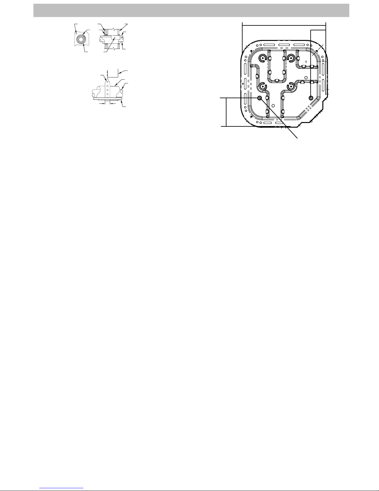
INSTALL ON SOLID, LEVEL MOUNTING PAD
If conditions or local codes require the unit be attached to
pad, tie−down bolts should be used and fastened through
knockouts provided in unit base pan. Refer to unit mounting
pattern in Fig. 2 to determine base pan size and knockout
hole location.
Arrange supporting members to adequately support unit and
minimize transmission of vibration to building. Consult local
codes governing rooftop applications.
B
A
C
3/8” D (9.53) Tiiedown
Knockouts (2) Places
Base Pan
Width x Depth
in. (mm)
23-1/2 X 23-1/2
(596.9 X 596.9)
31-1/2 X 31-1/2
(800.1 X 800.1)
Tie Down
Knockouts in. (mm)
A B C
4-7/19
(111.0)
6-9/16
(166.7)
18-1/16
(458.8)
24-11/16
(627.1)
7-3/16
(182.6)
9−1/8
(231.8)
Minimum
Mounting
Pad
Dimensions
in. (mm)
26 x 26
(660 x 660)
35 X 35
(889 x 889)
A08073
Fig. 2 - Tie Down Knockouts
CLEARANCES
When installing, allow sufficient space for airflow clearance,
wiring, refrigerant piping, and service. Allow 24 in. (609.6
mm) clearance to service end of unit and 48 in. (1219.2 mm)
(above unit. For proper airflow, a 6−in. (152.4 mm) clearance
on 1 side of unit and 12−in. (304.8 mm) on all remaining
sides must be maintained. Maintain a distance of 24 in.
(609.6 mm) between units or 18 in. (457.2 mm) if no
overhang within 12 ft. (3.66 m) Position so water, snow, or ice
from roof or eaves cannot fall directly on unit.
NOTE: 18 in. (457.2 mm) clearance option described
above is approved for outdoor units with wire grille coil
guard only. Units with louver panels require 24 in. (609.6
mm) between units.
On rooftop applications, locate unit at least 6 in. (152.4 mm)
above roof surface.
OPERATING AMBIENT
The minimum outdoor operating ambient in cooling mode is
55_F (12.78_C), and the maximum outdoor operating
ambient in cooling mode is 125_F (51.67_C).
EXPANSION DEVICE
When combined with a Carrier indoor product, a hard shutoff,
thermostatic expansion valve (TXV) is required at the indoor
section of the system for proper operation.
3 501 01 3300 02
Specifications subject to change without notice.
 Loading...