

International comfort products RGH072, RGH102, RGH120, RGH110, RGH090 Installation Instructions Manual
...
INSTALLATION INSTRUCTIONS
R--410A Single Package Gas Heating /
Electric Cooling
RGH072 -- 120
NOTE: Read the entire instruction manual before starting
the installation
TABLE OF CONTENTS
SAFETY CONSIDERATIONS 2....................
Rated Indoor Airflow (cfm) 3..................
INSTALLATION 8...............................
Jobsite Survey 8................................
Step 1 -- Plan for Unit Location 8..................
Roof Mount 9...............................
Step 2 -- Plan for Sequence of Unit Installation 9......
Curb--Mounted Installation 9...................
Pad--Mounted Installation 9....................
Frame--Mounted Installation 9..................
Step 3 -- Inspect Unit 9...........................
Step 4 -- Provide Unit Support 9...................
Roof Curb Mount 9..........................
Slab Mount (Horizontal Units Only) 11..........
Alternate Unit Support
(In Lieu of Curb or Slab Mount) 11.............
Step 5 -- Field Fabricate Ductwork 11...............
Step 6 -- Rig and Place Unit 11....................
Positioning on Curb 12.......................
Step 7 -- Convert to Horizontal and Connect
Ductwork 12...........................
Step 8 -- Install Outside Air Hood 13...............
Economizer and Two Position Damper Hood
Package Removal and Setup — Factory Option 13..
Economizer Hood and Two--Position Hood 13.....
Step 9 -- Install Flue Hood 14.....................
Step 10 -- Install Gas Piping 14....................
Optional Thru--Base Connections
(Gas Connections) 15.........................
Step 11 -- Install External Condensate Trap and Line 17..
Step 12 -- Make Electrical Connections 17...........
Field Power Supply 17........................
Units with Factory--Installed
Non--Fused Disconnect 18.....................
Units without Factory--Installed
Non--Fused Disconnect 19.....................
All Units 19................................
Convenience Outlets 19.......................
Optional Thru--Base Connections
(Electrical Connections) 20...................
Units without Thru--Base Connections 21.........
Field Control Wiring 21.......................
Thermostat 21...............................
Unit without Thru--Base Connection Kit 21.......
Heat Anticipator Settings 22...................
EconoMi$er X (Factory--Installed Option) 22.......
2--Speed Indoor Fan Motor System with VFD
(Factory--Installed Option) 22....................
Hot Gas Re--Heat Control Connections 22..........
Hot Gas Re--Heat -- Space RH Controller 22......
Smoke Detectors 24...........................
Step 13 -- Adjust Factory--Installed Options 25........
Step 14 -- Install Accessories 25...................
START--UP CHECKLIST 31.......................
Specifications are subjec t to change without notice.
509 01 3808 00
09/2016
SAFETY CONSIDERATIONS
Improper installation, adjustment, alteration, service,
maintenance, or use can cause explosion, fire, electrical
shock or other conditions which may cause personal
injury or property damage. Consult a qualified installer,
service agency, or your distributor or branch for
information or assistance. The qualified installer or
agency must use factory--authorized kits or accessories
when modifying this product. Refer to the individual
instructions packaged with the kits or accessories when
installing.
Follow all safety codes. Wear safety glasses and work
gloves. Use quenching cloths for brazing operations and
have a fire extinguisher available. Read these instructions
thoroughly and follow all warnings or cautions attached to
the unit. Consult local building codes and appropriate
national electrical codes (in USA, ANSI/NFPA 70,
National Elec trical Code (NEC); in Canada, CSA C22.1)
for special requirements.
It is important to recognize safety information. This is the
safety--alert symbol
unit and in instructions or manuals, be alert to the
potential for personal injury.
. When you see this symbol on the
!
WARNING
ELECTRICAL SHOCK HAZARD
Failure to follow this warning could cause personal
injury or death.
Before performi ng service or m aintenance operations
on unit, turn off main power switch to unit and install
lock(s) and lockout tag(s). Ensure electrical service to
rooftop unit agrees with voltage and amperage l isted
on the unit rating plate. Unit may have more than one
power switch.
!
WARNING
UNIT OPERATION AND SAFETY HAZARD
Failure to follow this warning could cause personal
injury, death and/or equipment damage.
R--410A refrigerant systems operate at higher
pressures than standard R--22 systems. Do not use
R--22 service equipment or components on R--410A
refrigerant equipment.
Understand the signal words DANGER, WARNING,
CAUTION, and NOTE. These words are used with the
safety--alert symbol. DANGER identifies the most serious
hazards which will result in severe personal injury or
death. WARNING signifies hazards which could result in
personal injury or death. CAUTION is used to ide ntify
unsafe practices, which may result in minor personal
injury or product and property damage. NOTE is used to
highlight suggestions which will result in enhanced
installation, reliability, or operation.
!
WARNING
FIRE, EXPLOSION HAZARD
Failure to follow this warning could result in personal
injury or death.
Disconnect gas pipi ng from unit when leak testing at
pressure greater than 0.5 psig (3450 Pa). Pressures
greater than 0.5 psig (3450 Pa) will c ause gas valve
damage resulting in hazardous condition. If gas valve
is subjected to pressure greater than 0.5 psig (3450
Pa), it must be replaced before use. When pressure
testing field--supplied gas piping at pressures of 0.5
psig (3450 Pa) or less, a unit connected to such piping
must be isolated by closing the manual gas valve.
!
WARNING
PERSONAL INJURY AND ENVIRONMENTAL
HAZARD
Failure to follow this warning could cause personal
injury or death.
Relieve pressure and recover all refrigerant before
system repair or final unit disposal.
Wear safety glasses and gloves when handling
refrigerants. Keep torches and other ignition sources
away from refrigerants and oils.
!
CUT HAZARD
Failure to follow this caution may result in personal
injury.
Sheet metal parts may have sharp edges or burrs. Use
care and wear appropria te protective clothing, safety
glasses and gloves when handling parts and servicing
air--conditioning equipment.
CAUTION
2 509 01 3808 00
Specifications are subjec t to change without notice.
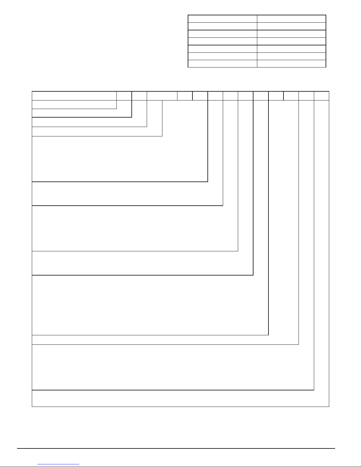
Rated Indoor Airflow (cfm)
The table to the right lists the rated indoor airflow used
for the AHRI efficiency rating for the units covered in this
document.
MODEL NUMBER NOMENCLATURE
Model Number Full Load Airflow (cfm)
RGH072 2400
RGH073 2400
RGH090 3000
RGH102 3000
RGH110 3000
RGH120 3000
MODEL SERIES
Position Number 1 2 3 4 5 6 7 8 9 10 11 12 13 14
R = Rooftop
G=Gas/Electric Type
H = High Efficiency Efficiency
072 = 72,000 = 6 tons (One Compressor)
073 = 73,000 = 6 tons (One Compressor)
090 = 90,000 = 7.5 tons (Two Compressors)
102 = 102,000 = 8.5 tons (Two Compressors)
110 = 110,000 = 10 tons (Two Compressors) 12 EER
120 = 120,000 = 10 tons (Two Compressors) 11.7 EER Nominal Cooling Capacity
H= 208/230--3--60
L = 460--3--60
S = 575--3--60 Vol t age
D = Low Heat
E = Medium Heat
F = High Heat
S = Low Heat, Stainless Steel Heat Exchanger
R = Medium Heat, Stainless Steel Heat Exchanger
T = High Heat, Stainless Steel Heat Exchanger Heating Capacity *
A = Standard Static Motor
B = High Static Motor
C = Medium Static Motor Motor Options
A = None
B = Economizer w/ Barometric Relief, OA Temp Sensor
E = Economizer w/ Barometric Relief + CO2Sensor, OA Temp Sensor
H = Economizer w/ Barometric Relief, Enthalpy Sensor
L = Economizer w/ Barometric Relief + CO2Sensor, Enthalpy Sensor
P = 2--Position Damper w/ Barometric Relief
U = Temperature Ultra Low Leak Economizer w/ Barometric Relief
W = Enthalpy Ultra Low Leak Economizer w/ Barometric Relief Outdoor Air Opti ons / Contr ol
0A = No Options Factory--Installed Options*
A = Aluminum / Copper Condenser and Evaporator Coils
B = Pre--Coat Aluminum / Copper Condenser and Aluminum / Copper Evaporator Coils
C = E --Coat Aluminum / Copper Condenser and Aluminum / Copper Evaporator Coils
D = E --Coat Aluminum / Copper Condenser and E--Coat Aluminum / Copper Evaporator Coils
E = Copper / Copper Condenser and Aluminum / Copper Evaporator Coils
F = Copper / Copper Condenser and Copper / Copper Evaporator Coils Condenser / Evaporator Coil Configuration
A = Standard Motor
T = 2--Speed Indoor Fan VFD Controller (for 2--stage units only) Indoor Fan Motor Speed
* See RGH 3 to 12.5 ton Product Specification for details.
R G H 0 9 0 H D A A 0 A A A
509 01 3808 00 3
Specifications are subjec t to change without notice.
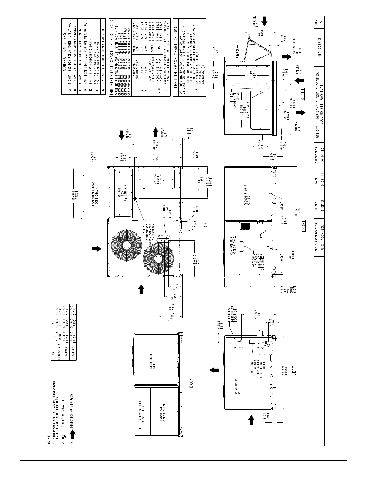
Fig. 1 -- RGH 072--102 Unit Dimensional Drawing, sheet 1 of 2
4 509 01 3808 00
Specifications are subjec t to change without notice.
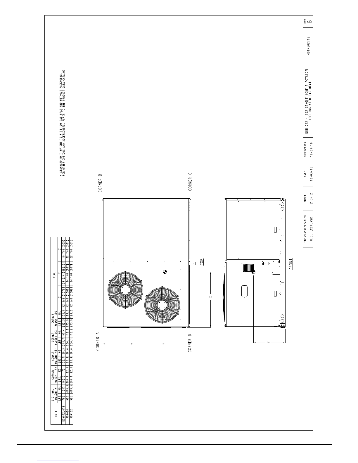
Fig. 1 -- RGH 072--102 Unit Dimensional Drawing, sheet 2 of 2
509 01 3808 00 5
Specifications are subjec t to change without notice.
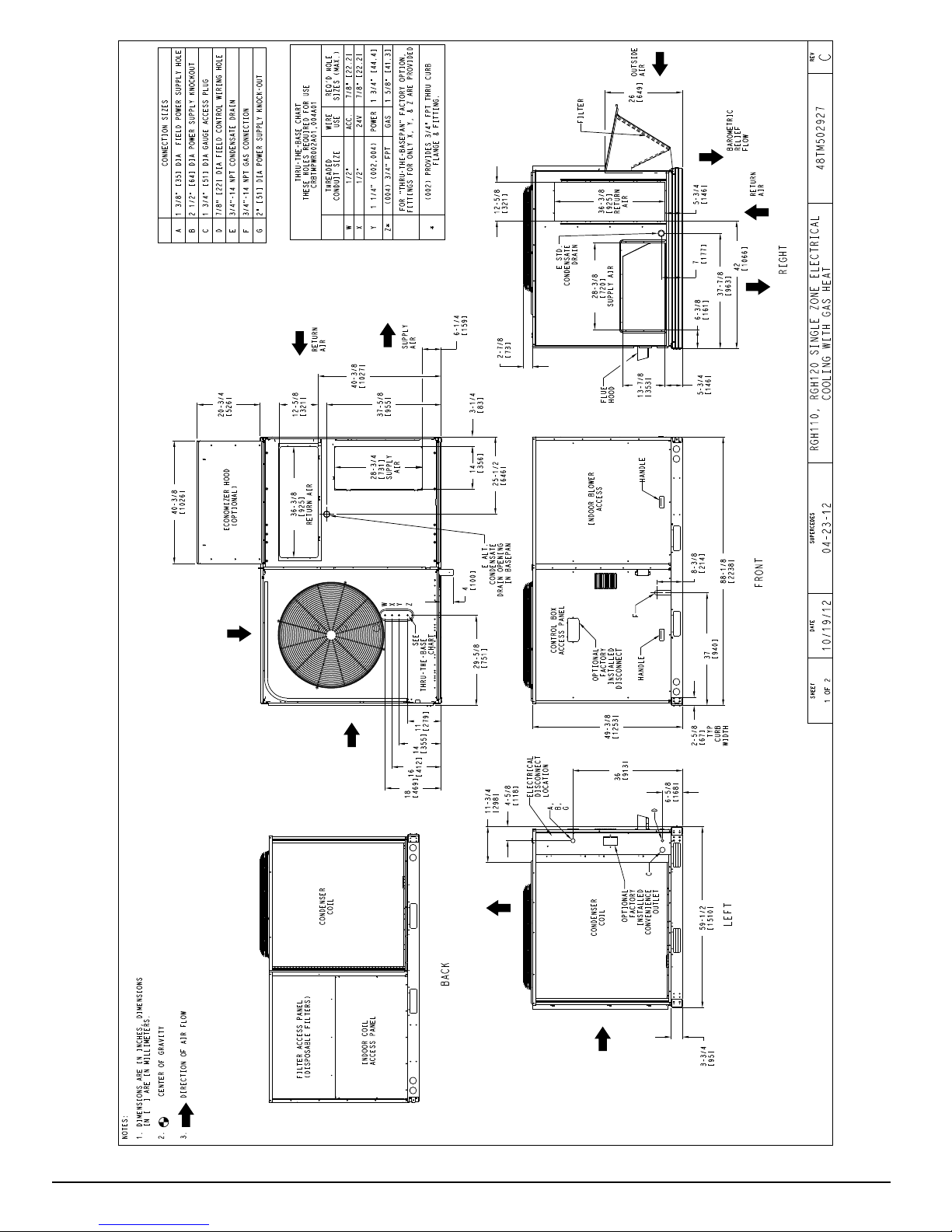
Fig. 2 -- RGH 110-- 120 Unit Dimensional Drawing, sheet 1 of 2
6 509 01 3808 00
Specifications are subjec t to change without notice.
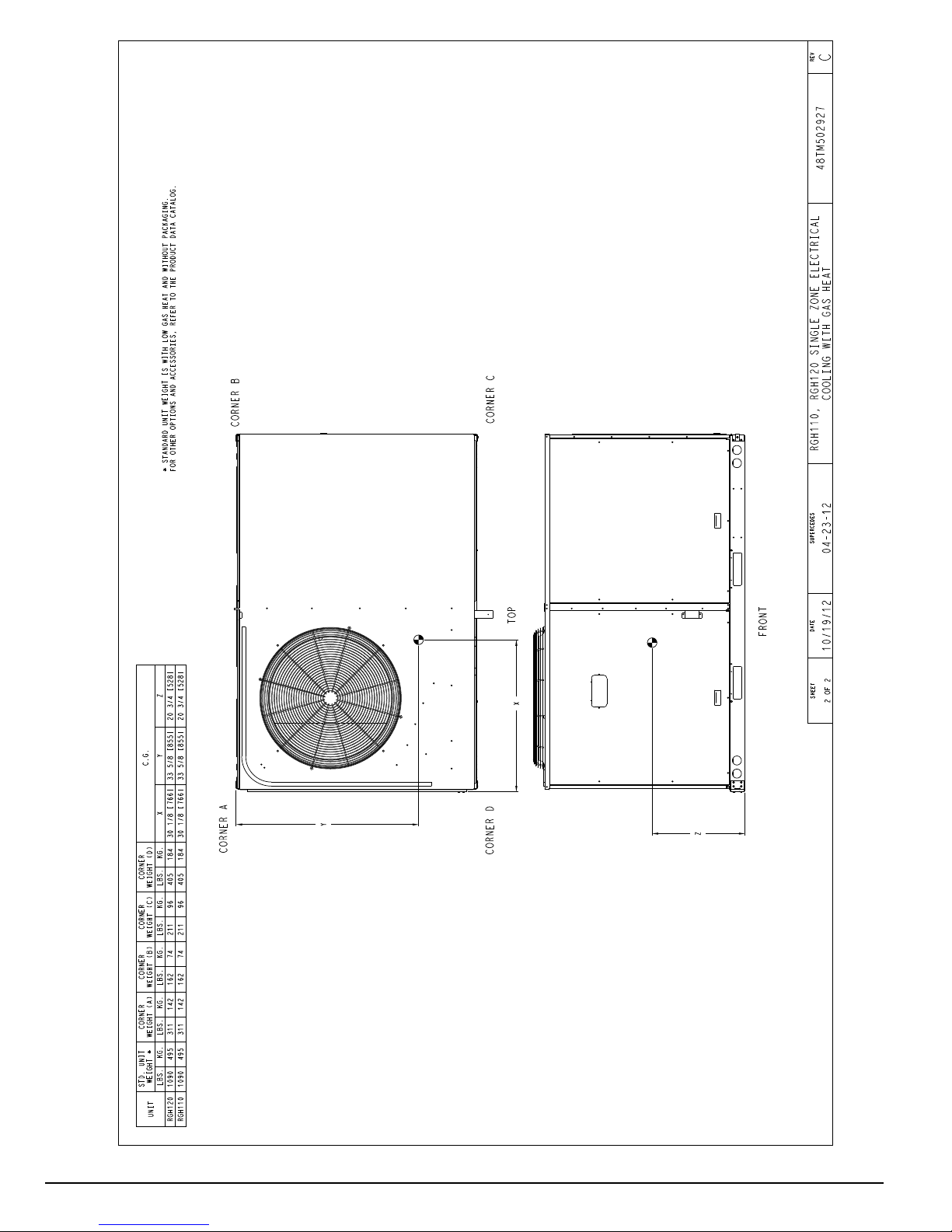
Fig. 2 -- RGH 110--120 Unit Dimensional Drawing, sheet 2 of 2
509 01 3808 00 7
Specifications are subjec t to change without notice.
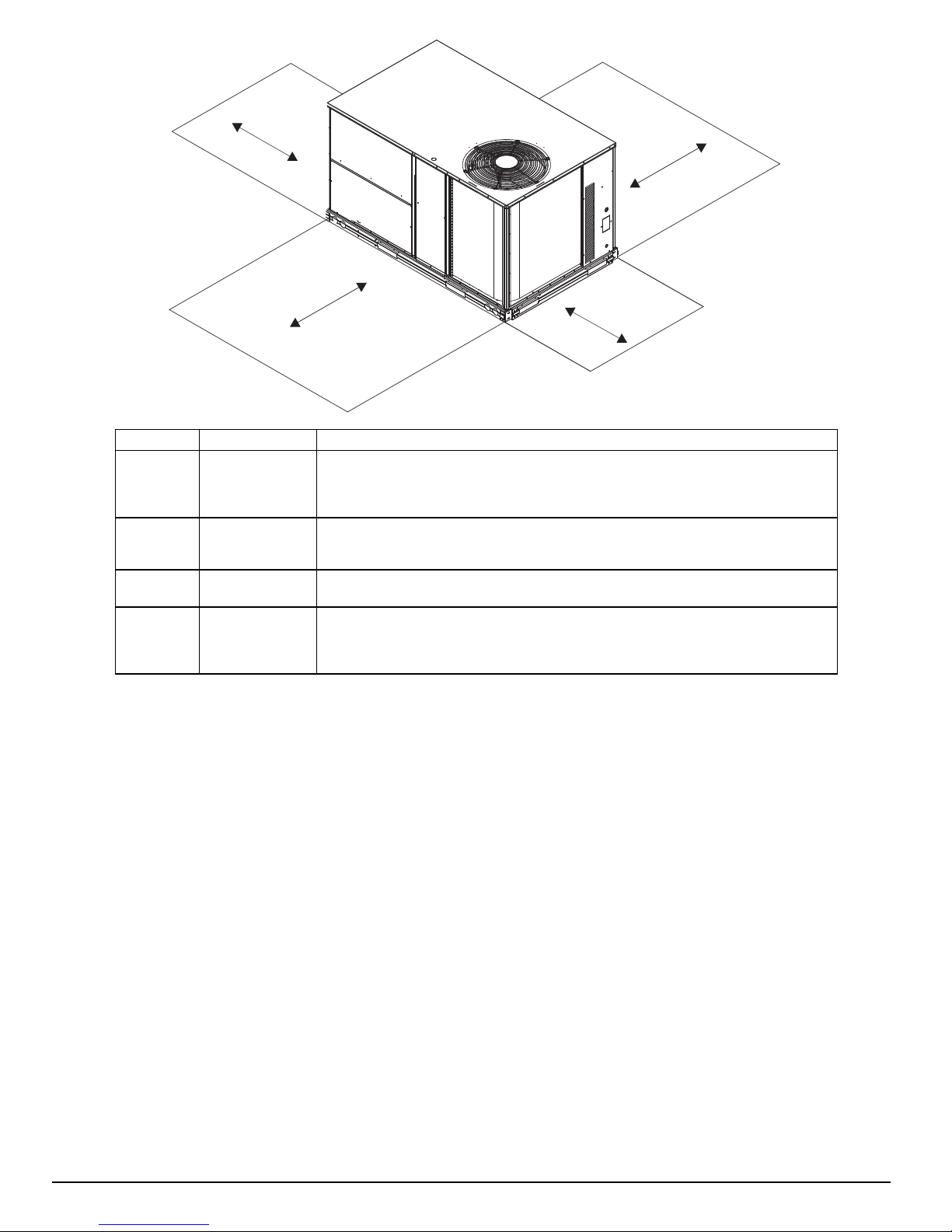
C
D
B
A
LOCATION DIMENSION CONDITION
48---in (1219 mm)
A
B
C
D
NOTE: Unit not designed to have overhead obstruction. Contact Application Engineering for guidance on any application
18---in (457 mm)
18---in (457) mm
12---in (305 mm)
42---in (1067 mm)
36---in (914 mm)
Special
36---in (914 mm)
18---in (457 mm)
48---in (1219 mm)
42---in (1067 mm)
36---in (914 mm)
Special
planning overhead obstruction or for vertical clearances.
Unit disconnect is mounted on panel
No disconnect, convenience outlet option
Recommended service clearance
Minimum clearance
Surface behind servicer is grounded (e.g., metal, masonry wall)
Surface behind servicer is electrically non - -- conductive (e.g., wood, fiberglass)
Check sources of flue products within 10--- ft of unit fresh air intake hood
Side condensate drain is used
Minimum clearance
No flue discharge accessory installed, surface is combustible material
Surface behind servicer is grounded (e.g., metal, masonry wall, another unit)
Surface behind servicer is electrically non - -- conductive (e.g., wood, fiberglass)
Check for adjacent units or building fresh air intakes within 10 - -- ft (3 m) of this unit’s flue outlet
Fig. 3 -- Servic e Clearance Dimensional Drawing
C08337
INSTALLATION
Jobsite Survey
Complete the following checks before installation.
1. Consult local building codes and the NEC (National
Electrical Code) (ANSI/NFPA 70) for special installation requirements.
2. Determine unit location (from project plans) or select
unit location.
3. Check for possible overhead obstructions which may
interfere with unit lifting or rigging.
Step 1 — Plan for Unit Location
Select a location for the unit and its support system (curb
or other) that provides for the minimum clearances
required for safety. This includes the clearance to
combustible surfaces, unit performance and service access
below, a round and above unit as specified in unit
drawings. See Fig. 3.
NOTE: Consider also the effect of adjacent units.
8 509 01 3808 00
Be sure t hat the unit is installed such that snow will not
block the combustion intake or flute outlet.
Unit may be installed directly on wood flooring or on
Class A, B, or C roof--covering material when roof curb is
used.
Do not install unit in an i ndoor location. Do not locate air
inlets near exhaust vents or other sources of contaminated
air. For proper unit operation, adequate combustion and
ventilation air must be provided in accordance with
Section 5.3 (Air for Combustion and Ventilation) of the
National Fuel Gas Code, ANSI Z223.1 (American
National Standards Institute) and NFPA (National Fire
Protection Association) 54 TIA-- -- 54 ----84----1. In Canada,
installation must be in accordance with the CAN1-- --B149
installation codes for gas burning appliances.
Although unit is weatherproof, avoid locations that permit
water from highe r leve l runoff and overhangs to fall onto
the unit.
Locate mechanical draft system flue assembly at least 4 ft
(1.2 m) from any opening through which combusti on
products could enter the building, and at least 4 ft (1.2 m)
Specifications are subjec t to change without notice.
from any adjacent building (or per local code). Locate the
flue assembly at least 10 ft (3.05 m) from an adjacent
unit’s fresh air intake hood if within 3 ft (0.91 m) of same
elevation (or per local code). When unit is located
adjacent to public walkways, flue assembly must be at
least 7 ft (2.1 m) above grade.
Select a unit mount ing system that provides adequate
height to allow installation of condensat e trap per
requirements. Refer to Step 11 — Install External
Condensate Trap and Line – for required trap dimensions.
Roof Mount —
Check building codes for weight distribution
requirements. Unit operating weight is shown in Table 1.
Step 2 — Plan for Sequence of Unit Installation
The support method used for this unit will dictate different
sequences for the steps of unit installation. For example,
on curb--mounted units, some accessories must be
installed on the unit before the unit i s placed on the curb.
Review the following for recom mended sequences for
installation steps.
Rig and place unit
Convert unit to side duct connection arrangement
Install field--fabricated ductwork at unit duct openings
Install outdoor air hood
Install flue hood
Install gas piping
Install condensate line trap and piping
Make electrical connections
Install other accessories
Frame--mounted installation —
Frame--mounted applications generall y follow the
sequence for a curb installation. Adapt as required to
suit specific installation plan.
Step 3 — Inspect unit
Inspect unit for transportation damage. File any claim
with transportation agency.
Confirm before installation of unit that voltage, amperage
and circuit protection requirements listed on unit data
plate agree with power supply provided.
Curb--mounted Installation —
Install curb
Install field--fabricated ductwork inside curb
Install accessory thru--base service connection package
(affects curb and unit) (refer to accessory installation
instructions for details)
Prepare bottom condensate drain connection to suit
planned condensate line routing (refer to Step 11 for
details)
Rig and place unit
Install outdoor air hood
Install flue hood
Install gas piping
Install condensate line trap and piping
Make electrical connections
Install other accessories
Pad--mounted Installation —
Prepare pad and unit supports
Check and tighten the bottom condensate drain
connection plug
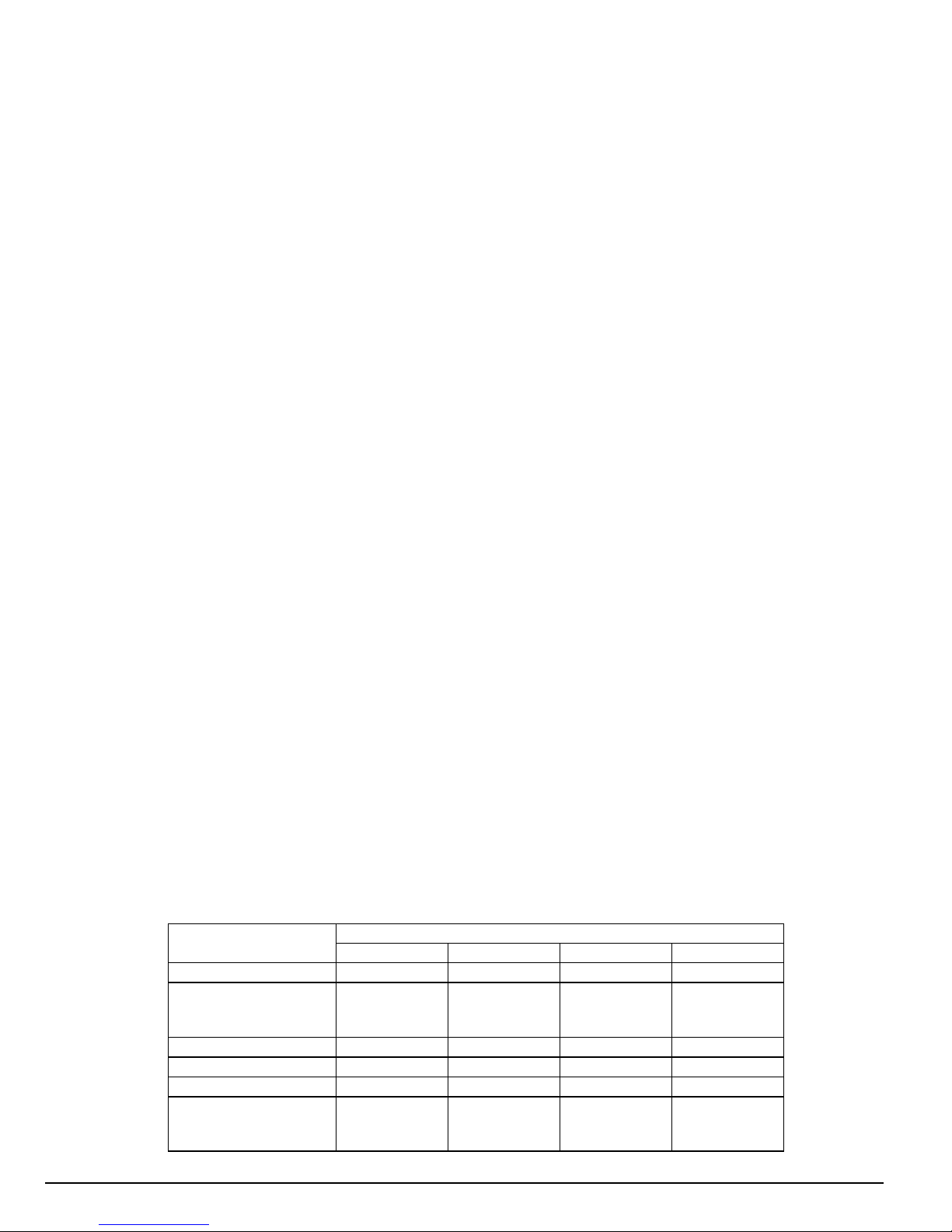
Table 1 – Operating Weights
RGS
Base Unit 765 (347) 925 (419.5) 925 (419.5) 1090 (495)
Economizer
Vertical 75 (34) 75 (34) 75 (34) 75 (34)
Horizontal 122 (55) 122 (55) 122 (55) 122 (55)
Hot Gas Re - -- Heat System
Cu Fins 25 (11) 43 (20) 56 (25) 73 (33)
Powered Outlet 35 (16) 35 (16) 35 (16) 35 (16)
Curb
14---in/356 mm 143 (65) 143 (65) 143 (65) 143 (65)
24---in/610 mm 245 (111) 245 (111) 245 (111) 245 (111)
1
Not avail able for size 110 units.
1
072/073 090 102 110/120
80 (36) 80 (36) 80 (36) 85 (39)
On units with hinged pane l option, check to be sure all
latches are snug and in closed position.
Locate the carton containing the outside air hood parts;
see Fig. 9 on page 13. Do not remove carton until unit has
been rigged and located in final position.
Step 4 — Provide Unit Support
Roof Curb Mount —
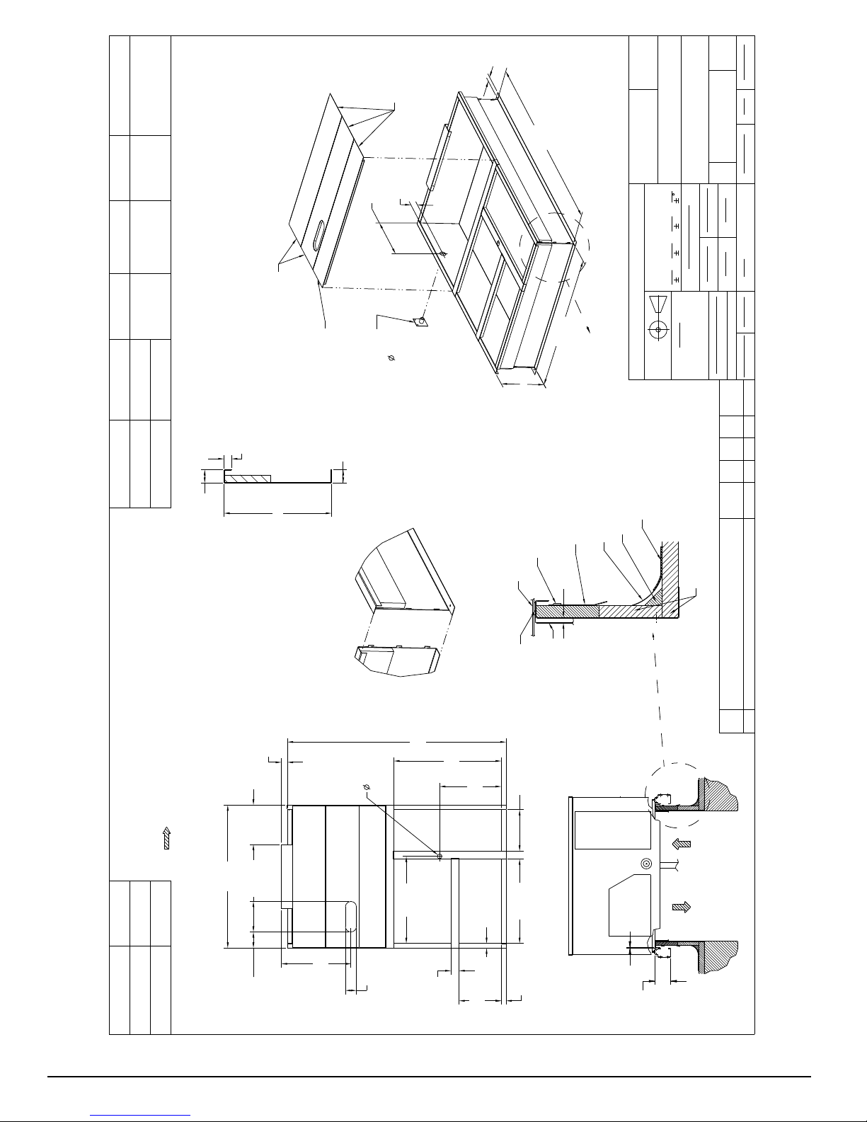
Accessory roof curb details and di mensions are shown in
Fig. 4. Assemble and install accessory roof curb in
accordance with instructions shipped with the curb.
NOTE: The gasketing of the unit to the roof curb is
critical for a watertight seal. Install gasket supplied with
the roof curb as shown in Fig. 4. Improperly applied
gasket can also result in air leaks and poor unit
performance.
Curb should be level. This is necessary for unit drain to
function properly. Unit leveling tolerances are shown in
Fig. 5. Refer to Accessory Roof Curb Installation
Instructions for additional i nformation as required.
UNITS LB (KG)
509 01 3808 00 9
Specifications are subjec t to change without notice.
1-3/4"
TYP
[44.5]
C
ACCESSORY CONVENIENCE
OUTLET WIRING CONNECTOR
FITTING
1/2" [12.7] NPT 1/2" [12.7] NPT
CONTROL WIRING
FITTING
POWER WIRING
3/4" [19] NPT 1 1/4" [31.7] NPT
THRU THE CURB
CRBTMPWR004A01 THRU THE BOTTOM
CRBTMPWR002A01
CONNECTOR PKG. ACC. GAS CONNECTION TYPE GAS FITTING
1 3/4"
[44.5]
1.00"
[25.4]
12-1/2" [317.5] WIDE
INSULATED DECK PANELS
INSULATED DECK PANEL
9-15/16" [252.4] WIDE
"A"
1 3/4"
[44.4]
SEE NOTE #2
2-3/8"
[61]
20-3/4"
[513]
INSIDE
GAS SERVICE PLATE
THRU THE CURB
DRILL HOLE
2" [50.8] @
ASSEMBLY (IF
REQUIRED)
(SEE NOTE #8)
SECTION THRU SIDE
RETURN AIR
SUPPLY AIR
UNIT
[1987.5]
6' 6-1/4"
4' 2"
[1270.0]
"A"
NAIL (FIELD SUPPLIED)
TYPICAL (4) SIDES
7/16"
CERTIFIED DRAWING
SEE VIEW "B"
ROOFING FELT
(FIELD SUPPLIED)
COUNTER FLASHING
(FIELD SUPPLIED)
[11]
CURB ASY, ROOF
THIS DOCUMENT AND THE INFORMATION CONTAINED THEREIN
IS PROPRIETARY TO CARRIER CORPORATION AND SHALL NOT
BE USED OR DISCLOSED TO OTHERS, IN WHOLE OR IN PART,
WITHOUT THE WRITTEN AUTHORIZATION OF CARRIER CORPORATION.
1029120
TOLERANCES ON:
AUTHORIZATION NUMBER TITLE
DIMENSIONS ARE IN INCHES
----
UNLESS OTHERWISE SPECIFIED
1 DEC 2 DEC 3 DEC ANG
PRODUCTION
---
MATERIAL
DRAWING RELEASE LEVEL:
THIRD ANGLE
PROJECTION
ROOFING MATERIAL
(FIELD SUPPLIED)
CANT STRIP
(FIELD SUPPLIED)
RIGID INSULATION
SHEET 5 OF 5
50HJ405012
SIZE DRAWING NUMBER REV
D
-
-
-
DRAFTER CHECKER
ENGINEERING MANUFACTURING
MMC 12/16/09 - -
-
-
T-005, Y-002
WEIGHT:
- PURCH - N/A -
ENGINEERING REQUIREMENTS
SURFACE FINISH MFG/PURCH MODEL (INTERNAL USE ONLY) NEXT DRAWING SCALE DISTRIBUTION
ECN NO.APP'DCHK'DBYDATEREVISION RECORDREV
1067898--MMC4/22/13
(FIELD SUPPLIED)
2 1/4"
[57.2]
14 3/4"
[374.7]
NOTES:
1. ROOFCURB ACCESSORY IS SHIPPED DISASSEMBLED.
2. INSULATED PANELS: 25.4 [1"] THK. POLYURETHANE FOAM, 44.5 [1-3/4] # DENSITY.
3. DIMENSIONS IN [ ] ARE IN MILLIMETERS.
4. ROOFCURB: 18 GAGE STEEL.
5. ATTACH DUCTWORK TO CURB. (FLANGES OF DUCT REST ON CURB).
6. SERVICE CLEARANCE 4 FEET ON EACH SIDE.
7. DIRECTION OF AIR FLOW.
8. CONNECTOR PACKAGE CRBTMPWR002A01 IS FOR THRU-THE-CURB GAS TYPE
PACKAGE CRBTMPWR004A01 IS FOR THRU-THE-BOTTOM TYPE GAS CONNECTIONS.
53 1/2"
[1358.9]
11.42"
[290.0]
A
14"
24"
[356]
[610]
26"
[660.4]
6 3/64"
ROOF CURB
ACCESSORY #
CRRFCURB003A01
CRRFCURB004A01
[153.5]
1 3/4"
[44.4]
4 3/16"
[106.0]
81 3/4"
[827.1]
32 9/16"
[2076.3]
3"
40 3/16"
[76.2]
[1020.8]
VIEW "B"
CORNER DETAIL
[585.8]
23 1/16"
OPENING
RETURN AIR
OPENING
SUPPLY AIR
1 3/4"
[44.5]
[401.6]
15 13/16"
DUCT
GASKET
(FIELD SUPPLIED)
(SUPPLIED WITH CURB)
15 15/32
[392.9]
[800.9]
31 17/32"
1 3/4"
[44.5]
6' 61/4" WAS 6' 7 1/6", 4'2' WAS 4' 2 13/16";
18 GA WAS 16 GA.; 15 13/16" WAS 15 15/16"; NAIL
FIELD SUPPLIED WAS WITH CURB
C
SUPPLY AIR RETURN AIR
1/4"
[7.0]
[115.5]
4 9/16"
10 509 01 3808 00
C13311
Fig. 4 -- Roof Curb Details
Specifications are subjec t to change without notice.
 Loading...