

International comfort products PH55 Series, PYPA Series Installation Instructions Manual
DIRECT DRIVE BLOWER
PH55/PYPA SERIES
THREE PHASE
SINGLE PACKAGE HEAT
PUMPS
ELECTRIC HEAT
(OPTIONAL)
TABLE OF CONTENTS
1. SAFETY LABELING AND SIGNAL WORDS 2....................
2. UNIT DIMENSIONS 2......................................
3. SAFE INSTALLATION REQUIREMENTS 2.......................
4. LOCATING THE UNIT 2....................................
5. UNIT ELECTRICAL WIRING 4................................
6. ELECTRIC HEAT INSTALLATION GENERAL INFORMATION 6.......
7. AIR DISTRIBUTION SYSTEM 8..............................
8. START- UP PROCEDURES 8................................
9. SEQUENCE OF OPERATION 10.............................
Printed in U.S.A.
LP--1 10/15/01
427 01 1005 00
1. Safety Labeling and Signal Words
Danger, Warning and Caution
The signal words DANGER, WARNING and CAUTION are used to identify levels of hazard seriousness. The signal word DANGER is
only used on product labels to signify an immediate hazard. The signal words WARNING and CAUTION will be used on product labels
and throughout this manual and other manuals that may apply to the product.
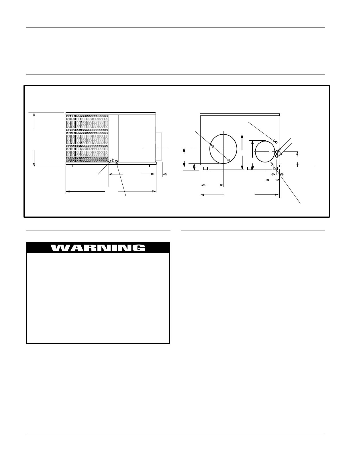
2. Dimensions
NOTE: DUCT COLLARS ATTACHED TO SUPPLY AND RETURN MUST BE REVERSED AT INSTALLATION. SEE INSTRUCTIONS ON PAGE 3.
ALL DIMENSIONS IN INCHES
COIL
ROUND FLANGE
WILL
ACCOMMODATE
14” DIA.
RETURN DUCT
3
/
DIA HOLE**
8
ACCESS
261/
2
PRESSURE
PORTS
* ELECTRICAL ACCESS FOR LINE VOLTAGE POWER SUPPLY--ONE FOR UNIT, ONE FOR HEATER
**
FOR LOW VOLTAGE WIRING
3. Safe Installation Requirements
PANEL
26
51
CONDENSATE DRAIN
3
/
4
CONNECTION
10
3
11/
2
121/
2
4. Locating The Unit
The unit is designed for outdoor installation only. Place the unit on
a platform at ground level. The unit may be installed on a concrete
slab of 48² (1219mm) x 48² (1219mm) dimensions. Cement
Installation or repairs made by unqualified persons can
result in hazards to you and others. Installation MUST
conform with local building codes or, in the absence of
local codes, with the National Electrical Code
NFPA70--1990 or current edition.
The information contained in this manual is intended
for use by a qualified service technician familiar with
safety procedures and equipped with the proper tools
and test instruments.
Failure to carefully read and follow all instructions in
this manual can result in unit malfunction, property
damage, personal injury and/or death.
blocks on a 3’’ sand footing will also work. The slab or blocks
SHOULD NOT be in contact with any part of the structure. Check
local codes covering zoning, noise, platforms, etc..
If practical avoid locating next to fresh air intakes, vent or bedroom windows. Noise may carry into the openings and disturb
people inside.
Avoid installations under roof overhangs without guttering. Water
draining from the roof onto the unit could produce excessive
noise, and may cause ice to build up on coil or fan.
Placement of the unit should be in a well drained area or the unit
MUST be supported high enough so runoff will not enter the unit.
Do not locate unit where heat, lint or exhaust fumes will be discharged on unit (as from dryer vents.)
41
17
14
11/4DIA.*
1
1
/4DIA.*
3
/
4
8
ROUND SHAPED FLANGE WILL
ACCOMMODATE 12” DIA.
SUPPLY DUCT
9
1
1
/
2
· Seal supply and return air ducts.
· Check to see that filters are installed correctly and are the
proper type and size.
NOTE: It is the personal responsibility and obligation of the customer to contact a qualified installer to ensure that the installation
is adequate and conforms to governing codes and ordinances.
CAUTION
Do NOT operate unit in a corrosive atmosphere containing
chlorine, fluorine, or any other corrosive chemicals.
Clearances
Minimum clearances, as specified in FIGURE 1, MUST be maintained from adjacent structures to provide adequate air circulation and room for service personnel.
While minimum clearances are acceptable for safety reasons,
they may not allow adequate air circulation around the unit for
proper operation. Whenever possible, it is desirable to allow additional clearance, especially around the condenser inlet and dis charge openings.
Do NOT install the unit i n a recessed or confined area that will permit discharged air from the condenser to recirculate to the condenser inlet.
2
427 01 1005 00
Minimum Clearances to Combustible Construction
SERVICE ACCESS CLEARANCES
Blower Access Panel Side 30² (762mm)...................
Electrical Access Panel Side 30² (762mm).................
OPERATIONAL CLEARANCES
Combustible Base
(Wood or Class A, B or C
roof covering material) 0²....................
Supply and Return Air Ducts 0²...........................
Duct Connection Side
Clearance between Overhang
and Top of Unit 48² (1219mm)...............
Clearance around Condenser Coil area to wall or shrubs 10’’.
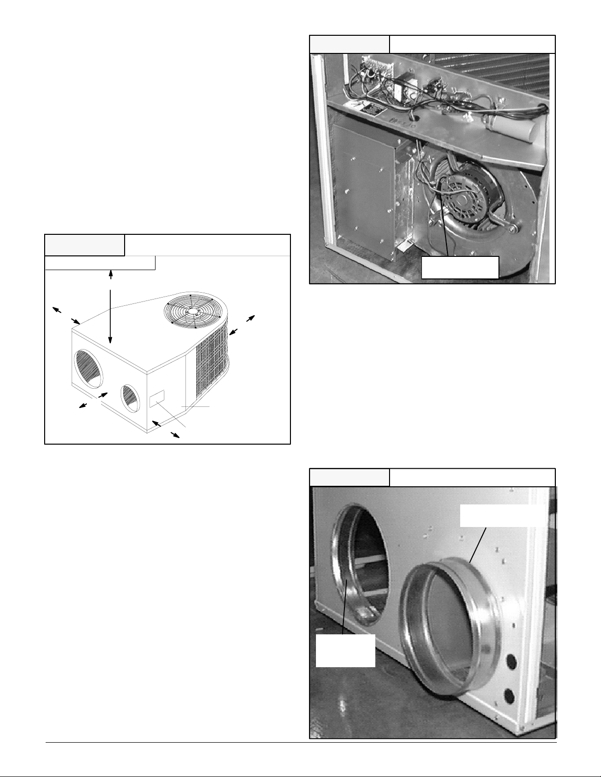
Blower CompartmentFIGURE 2
0².......................................
FIGURE 1
Overhang
Evaporator
Access Panel
30’’
Recommended
48’’ Minimum Overhang Clearance
6’’
Installation
Minimum Clearances and Access Panels
around
10’’
condenser
coil area
.
.
.
.
.
.
30’’
Blower/Electrical
Access Panel
Cover Plate
CAUTION
Blower Terminal
Block
Installing Duct Collars
Duct collars are supplied with the unit and are attached to the supply and return openings with the flanges to the inside and must be
reversed before unit’s installation.
1. Remove the screws from the collars and reverse them so
the flange is to the outside.
2. Make sure when pushing the collars into place that the ’’V’’
flange of the collars seats into the supply and return holes
securely.
3. Re--install screw in each collar so it goes through both of the
holes in the collar end. It does not matter how the ends of
the collar overlap in order to accomplish this.
Duct Collar InstallationFIGURE 3
Collar Installed for
Duct Connections
The unit must be installed with a slope no greater than1/8²
per foot (10mm per meter). For side to side leveling, the condensate drain side side MUST always be lower.
-- The unit MUST be situated in such a way as to provide safe
access for servicing.
-- The platform may be made of either concrete or pressure
treated wood and MUST be level and strong enough to
support the unit’s weight.
-- Position platform separate from the building’s foundation.
-- Install in a well--drained area, with the top surface of the
platform above grade level and above the average winter
snow levels to prevent coil blockage.
-- Platform MUST be high enough to allow for proper condensate drainage.
Collar as
shipped with
unit
3
427 01 1005 00
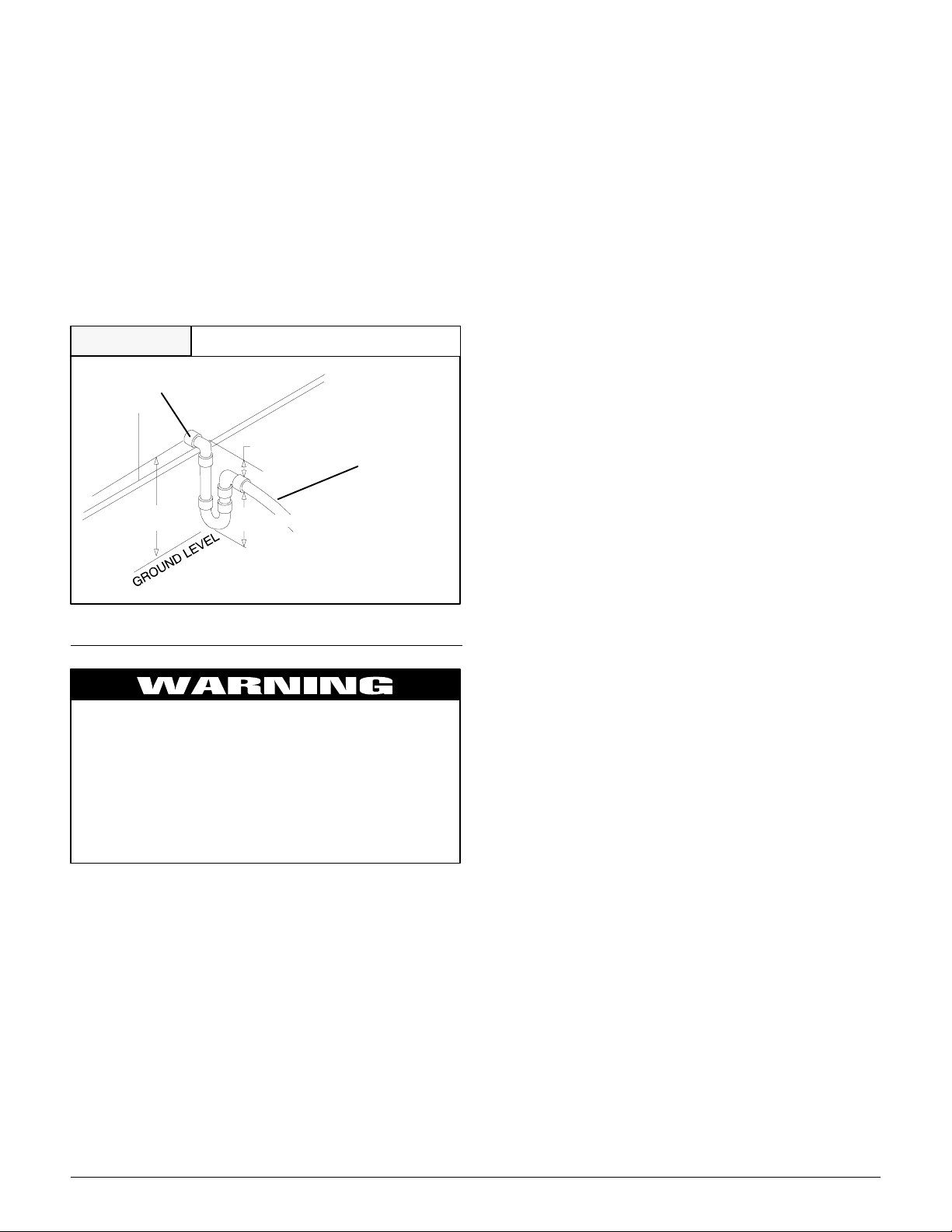
Condensate Drain
The condensate drain outlet is a3/4² (19.1mm) threaded female
PVC connection located at the bottom of the unit to the left of the
evaporator access panel .
The circulating blower and the condenser fan create a negative
pressure on the condensate drain line that will prevent the condensate from draining properly without a trap. Tocombatthis negative pressure, a field supplied condensate trap that will allow a
standing column of water of at least 2² (50.8mm) MUST be
installed. The outlet of the trap must be at least 1’’ below the unit
drain connection. Install the trap as near to the unit as possible
forproperdrainage.
3
/4² (19.1mm) drain line MUST be installed if required by local
A
codes or if location of unit requires it. Run the drain line to an open
drain or other suitable disposal point.
FIGURE 4
3
/4² (19.1mm)
Threaded Female
PVC Fitting
33/4²
(82.5mm)
Condensate Drain Information *
1²
(25.4mm)
2² (50.8mm)
* Condensate trap MUST be installed.
3
/4² (19.1mm)
Drain Line
Ground Connections
A ground lug is installed on the control plate (or electric heat
mounting plate) for the ground connection. Use a copper conductor of the appropriate size from the unit to a grounded connection
in the electrical service panel ortoaproperlydriven andelectrically grounded ground rod. See warning on this page.
Line Voltage Wiring
Do NOT complete line voltage connections until unit is permanently grounded. All line voltage connections and the ground connection MUST be made with copper wire.
Connections for line voltage are made on the unit electrical control plate (see NO TAG). For access, remove the Blower/Electrical access panel.
Refer to applicable wiring diagram in this Manual. Complete the
line service connections to the contactor ‘L1, L2, L3’ terminals on
the electrical control plate. Check all screw terminals to ensure
they are tight.
NOTE: If an Electric Heat Accessory is installed, refer to the Electric Heat Accessory section of this manual to determine line voltage connections. The Electric Heat Accessory mounts inside the
unit in the heater box. Field supplied line voltage wires for the
Electric Heat Accessory (separate from the field supplied line
voltage wires to the unit) connect to the appropriate circuit breaker (if used) in the Electric Heat Accessory.
Converting 230V Units to 208V
To convert 230V units to 208V:
1. Turn electric power OFF .
5. Unit Electrical Wiring
Electrical shock hazard.
Disconnect power at fuse box or service panel before
making any electrical connections.
Unit MUST be grounded to electrical service panel.
Failure to follow this warning can result in property
damage, personal injury, and/or death.
NOTE: All electrical work MUST conform with the requirements of
local codes and ordinances and in the United States with National
Electrical Code ANSl/NFPA 70--1990 (or current edition). Provide
line voltage power supply from a separate fused circuit with a disconnect switch (when required) located within sight of the unit.
Supply voltage, amperage, fuse and disconnect switch sizes
MUST conform with local codes and ordinances.
Wiring MUST be protected from possible mechanical damage
and MUST NOT interfere with removal of access panels, filters,
etc.
All exposed line voltage connections MUST be made through liquid tight conduit to prevent water from entering the unit through
the electrical access..
2. Remove the blower/electrical access panel.
3. Locate the 24V control transformer.
4. Remove wire from the terminal labeled “240V” on the 24V
control transformer and reconnect it to the 208V terminal of
the 24V control transformer.
5. Replace the blower / electrical access panel.
Low Voltage Wiring
For access, removetheelectricalblower/electricalaccesspanel.
Refer to the connection wiring diagram for the applicable model
and to the instructions included with the thermostat.
Route low voltage wires through the port located on the rear panel
and up to the control box.
NOTE: If an Electric Heat Accessory is installed, see the Electric
Heat Accessory Installation Section of this manual for low voltage
connections.
Thermostat Connections
The location of the thermostat has an important effect on the operation of the unit. See the thermostat instructions for proper connection. See NO TAG for Low Voltage Wire Harness
Connections
4
427 01 1005 00
Field Installed Equipment
Wiring to be done in the field between the unit and other devices,
or between separatedeviceswhicharefield installed and located,
MUST NOT exceed the temperature limitations for type T wire
and MUST be installed according to the manufacturer’s instruc tions for the devices.
Final Electrical Check
Make a final wiring check to be s ure system is correctly wired. Inspect field installed wiring and the routing to ensure that rubbing
or chafing due to vibration will not occur.
NOTE: Wiring MUST be installed so it is protected from possible
mechanical damage.
FIGURE 5
NOTES: * Common maybe ‘‘B’’ or ‘‘X’’ on some T --stats.
[C]*[G] [R] [Y] [W]
[Blue] [Green] [Red] [Yellow] [White] [Orange]
Com
(when
used)
Electronic Thermostat Low Voltage Wiring
Harness Connection Diagram
Typical Thermostat Subbase
** ‘‘W’’ may be ’’W2’’ on some T--stats.
**
(when used)
W2
Fan 24V
Unit Low Voltage Wiring Harness.
Hot
Compressor
Elect.
Heat
Acces.
When outdoor
thermostat is
used, route this.
[O]
Reversing
valve
(energized
in cooling)
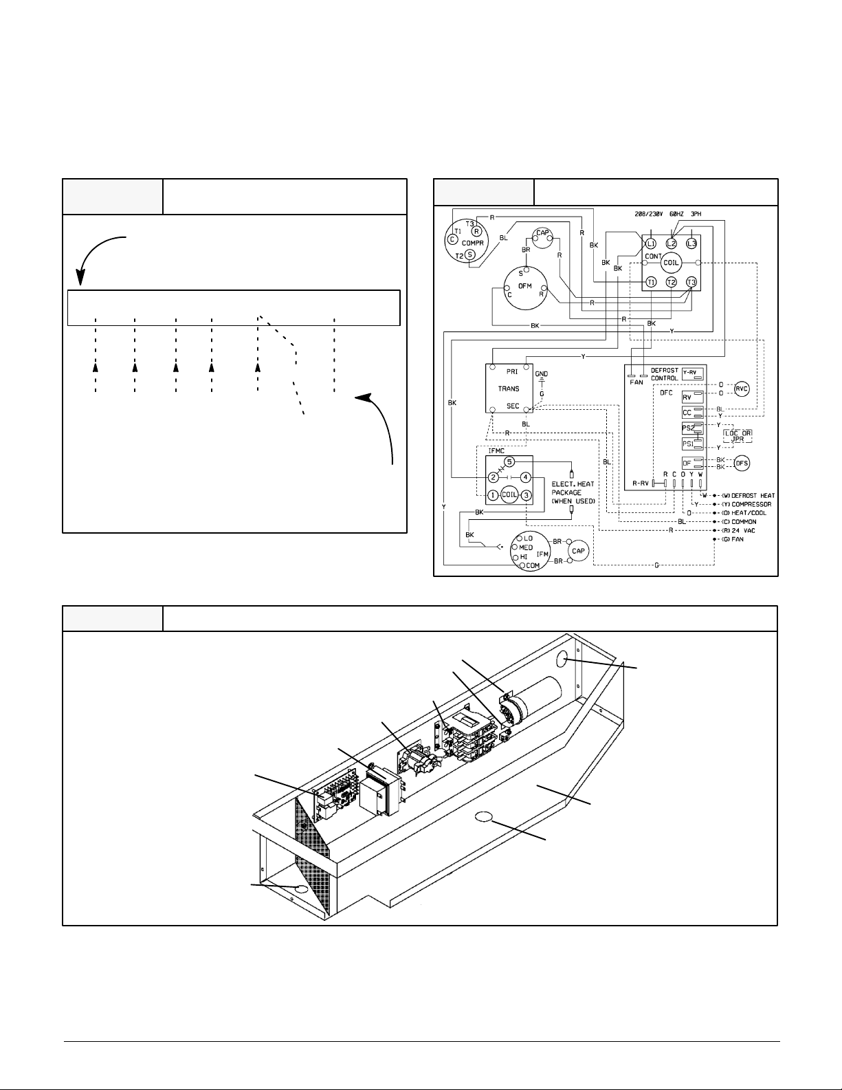
FIGURE 6
Typical Connections at Unit
FIGURE 7
Low Volt Wire Entrance
Control Box Configuration
Transformer
Defrost Board
Blower
Sequencer
Ground lug
Contactor
Condensor Fan
Capacitor
Component Wire
Opening
Control Box
Line Volt Wire Entrance
5
427 01 1005 00
 Loading...